operating instructions manual gamma/ l solenoid dosing...
TRANSCRIPT

ProM
inen
t®
Please read the operating instructions through completely before commissioning this equipment! Do not discard!Any part which has been subject to misuse is excluded from the warranty!
Part No. 987604 ProMinent Dosiertechnik GmbH • 69123 Heidelberg • Germany BA G 015 10/00 GB
Operating Instructions ManualProMinent® gamma/ LSolenoid Dosing Pump
Please affix nameplate here!

ProMinent®
Please fold out this page! �
Printing:Operating Instructions ProMinent® gamma/ L© ProMinent Dosiertechnik GmbH, 1999
Address:ProMinent Dosiertechnik GmbHIm Schuhmachergewann 5-11D-69123 HeidelbergPostfach 101760D-69007 [email protected]
Subject to technical alteration.
Printing

ProMinent®
Control elements and key functions
Control elements: overview
2
3
4
5
1
9 108
11
1213
7
6
1 LCD display2 Stroke length adjusting knob3 UP key4 P key5 DOWN key6 STOP/START key7 i key8 Fault indicator (red)9 Warning indicator (yellow)
10 Operating indicator (green)
11 “Dosing monitor” terminal12 “External control” terminal13 “Float switch” terminal
Key functions
In continuous display mode In settings mode(operating) (settings)
STOP/START key
STOPSTART
Press briefly Stop pump, Stop pump,start pump start pump
P key
P
Press briefly Start batch (in “batch” operating mode only), Confirm entry- jump to next menuCancel error option or continuous display
Press for 2 s Change to settings mode ---Press for 3 s --- Jump to continuous displayPress for 15 s Load factory settings (calibration) ---
i key
i
Press x1 Toggle between continuous displays Toggle between “change individual digits”and change a figure"
Press x2 --- For “change individual digits”:jumps to first digit
Arrow keys UP and DOWN
Press x1 Change directly alterable values Select other settings,(until “Set” appears) change individual digit or figure
Press simultaneously Prime ---

P
P
P P P P
P
P
P
PP P
PP P
PP PP
PP
P
P
P
P
P
P P
P
P
i
STOPSTOPSTARTSTART
edomBatchContactManualAnalog
edomAnalog
edomManual
edomContact
edomBatch
edoc
enon
1edoc
2edoc
0
9 9
0
9
0
9
0
tes
hctab
glanaSet
wolf
xua
sserp
bilac
raelc
9
0
9
0
9
0
9
0
6
0
ffo
no
02o mASet
Analog
024 mASet
Analog
evrucSet
Analog
11i mASet
Analog
01i mASet
Analog
12fFreq.
Set
Analog
02fFreq.
Set
Analog
11fFreq.
Set
Analog
01fFreq.
Set
Analog
91fFreq.
Set
Analog
01fFreq.
Set
Analog
91fFreq.
Set
Analog
01fFreq.
Set
Analog
92fFreq.
Set
Analog
92fFreq.
Set
Analog
02fFreq.
Set
Analog
02fFreq.
Set
Analog
91i mASet
Analog
01i mASet
Analog
91i mASet
Analog
01i mASet
Analog
22i mASet
Analog
02i mASet
Analog
92i mASet
Analog
02i mASet
Analog
92i mASet
Analog
02i mASet
Analog
noreSet
Analog
fforeSet
Analog
no
ffo
1
0
9
0
9
0
9
0
9
0
1
0
4p
1p
no
ffo
trats
0
6
0
9
0
9
0
9
0
9
0
10000
02451
tinu
tinu
2 s
-----Set
Analog
Set
Analog
Set
Analog
2
1
002
tctnc
no
ffo
9
0
9
0
9
0
9
0
Operating-/Settings DiagramContinuous
display
Start/stop pump
Change directly alterable values
= Lock (CODE 1)
= Lock (CODE 2)
Prime
Start batch (in"batch" operating mode only)
Cancel error
Check adjustable values
2
1

P
P P PP
PP
P PP P
P
P
iP
P
P
P
P
P
P
STOPSTART
PP P
P
P P
P
P P
P
P
P
edom
edom
edom
edom
edom
edoc
enon
1edoc
2edoc
0
9 9
0
9
0
9
0
tes
hctabSet
glana
wolfSet
xuaSet
sserpSet
bilacSet
raelc LN
9 *Set
MemBatch
0 *Set
MemBatch
9 *Set
MemBatch
0 *Set
MemBatch
9 *Set
MemBatch
0 *Set
MemBatch
9 *Set
MemBatch
0 *Set
MemBatch
6 *Set
MemBatch
0 *Set
MemBatch
ffoSet
MemBatch
noSet
MemBatch
02o
024
evruc
11i
01i
12f
02f
11f
01f
91f
01f
91f
01f
92f 92f
02f02f
91i
01i
91i
01i
22i
02i
92i
02i
92i
02i
nore
ffore
noSetFlow
ffoSetFlow
1SetFlow
0SetFlow
9SetFlow
0SetFlow
9SetFlow
0SetFlow
9Freq.
Set
Aux
0Freq.
Set
Aux
9Freq.
Set
Aux
0Freq.
Set
Aux
1Freq.
Set
Aux
0Freq.
Set
Aux
4pSet
1pSet
noSet
Calib
ffoSet
Calib
tratsSet
Calib
0Set
CalibN
6 LSet
Calib
0 LSet
Calib
9 LSet
Calib
0 LSet
Calib
9 LSet
Calib
0 LSet
Calib
9 LSet
Calib
0 LSet
Calib
9 LSet
Calib
0 LSet
Calib
10000Set
MemBatch
L
02451Set
MemBatch
L
tinu LSet
tinugal
Set
-----
Set
CalibN002
P P P
P PtctncSet
noSet
MemContact
ffoSet
MemContact
9Set
MemContact
0Set
MemContact
9Set
MemContact
0Set
MemContact
9Set
MemContact
0Set
MemContact
9Set
MemContact
0Set
MemContact
P

i
i
i
i
i
i
i
i
i
i
i
i
i
i
i
i
i
i
i
i
i
i
i
i
i
i
i
52 N*Mem
ContactStop
Operating mode "Analog" 0-20 mA
Stroke rate
Feed rate
Total stroke number
Total litres(feed quantity)
"External" display
Signal current
Strokes remaining
Batch size/Litres remaining
Factor
"Mem" appears only when "memory" function activated
Stroke length
Operating mode "Manual"
Continuous display
Operating mode "Contact" withmemory and tansfer factor 5
Operating mode "Batch" with memory and tansfer factor 5
653 N
AnalogStop
86321 L
AnalogStop
txeAnalog
Stop
002 mA
AnalogStop
56%
AnalogStop
56%
ManualStop
56%
ContactStop
56%
BatchStop
081Freq.
ManualStop
081Freq.
ContactStop
653 N
StopContact
081Freq.
BatchStop
653 N
StopBatch
057 /hL
ManualStop
653 N
StopManual
86321 L
StopContact
86321 L
StopBatch
86321 L
StopManual
txe
StopContact
Mem
txe
StopBatch
Mem
52 N*Mem
BatchStop
01000 L*Mem
BatchStop
*Mem
BatchStop
5*Mem
ContactStop
005
081Freq.
AnalogStop
057 /hL
AnalogStop
Continuousdisplay
= UP and/or DOWN arrow keys, directly alterable values

ProMinent®
Table of Contents
Table of Contents
Identcode
General User Guidelines
1 About This Pump ........................................................................................................................................................................ 1
2 Safety .................................................................................................................................................................................................... 1
3 Storage, Transport and Unpacking .......................................................................................................................... 2
4 Device Overview and Control elements .............................................................................................................. 2
4.1 Device overview ............................................................................................................................................................... 2
4.2 Control elements ............................................................................................................................................................. 3
5 Function Description ............................................................................................................................................................. 3
6 Assembly and Installation ................................................................................................................................................. 6
6.1 Assembling dosing pump ........................................................................................................................................ 6
6.2 Assembling tubing ......................................................................................................................................................... 6
6.2.1 Installation for non-self bleeding pumps .................................................................................. 6
6.2.2 Installation of self-bleeding pumps ............................................................................................... 8
6.3 Electrical Installation .................................................................................................................................................... 9
6.4 Retrofitting relays ............................................................................................................................................................ 12
7 Settings ............................................................................................................................................................................................... 14
7.1 Check adjustable values ........................................................................................................................................... 15
7.2 Change to settings mode ........................................................................................................................................ 15
7.3 Select operating mode (MODE menu) ........................................................................................................... 16
7.4 Settings for operating mode (SET menu) .................................................................................................... 16
7.4.1 Settings for “manual” operating mode ...................................................................................... 16
7.4.2 Settings for “analogue” operating mode (ANALG menu) ............................................ 16
7.4.3 Settings for “contact” operating mode (CONTCT menu) ........................................... 18
7.4.4 Settings for “batch” operating mode (BATCH menu) ..................................................... 20
7.5 Settings for programmable functions (SET menu) .............................................................................. 21
7.5.1 Settings for “calibration” function (CALIB menu) .............................................................. 21
7.5.2 Settings for the “pressure levels” function (PRESS menu) ........................................ 22
7.5.3 Settings for “auxiliary frequency” function (AUX menu) .............................................. 22
7.5.4 Settings for the “flow” function (FLOW menu) ..................................................................... 23
7.6 Setting code (CODE menu) .................................................................................................................................... 23
7.7 Cancel total stroke number or total litres (CLEAR window) ........................................................ 23
8 Commissioning ............................................................................................................................................................................ 24
8.1 Precision dosing settings ......................................................................................................................................... 25
8.2 Diagrams for setting feed capacity .................................................................................................................. 26
9 Operating ........................................................................................................................................................................................... 26
9.1 Manual operation ............................................................................................................................................................ 26
9.2 Remote control ................................................................................................................................................................. 27
10 Maintenance ................................................................................................................................................................................... 28
11 Repairs ................................................................................................................................................................................................ 28
12 Troubleshooting .......................................................................................................................................................................... 34
13 Decommissioning and Disposal ................................................................................................................................. 35

ProMinent®
Table of Contents
14 Technical Data .............................................................................................................................................................................. 36
14.1 Performance data and weights ........................................................................................................................... 36
14.2 Dosing reproducibility ................................................................................................................................................. 37
14.3 Viscosity ................................................................................................................................................................................. 37
14.4 Materials Data for Liquid ends ............................................................................................................................. 37
14.5 Electrical Data ................................................................................................................................................................... 37
14.6 Ambient conditions ....................................................................................................................................................... 38
14.7 Enclosure rating and safety class ..................................................................................................................... 38
14.8 Compatibility ...................................................................................................................................................................... 38
15 Accessories ..................................................................................................................................................................................... 39
Appendix ............................................................................................................................................................................................ 40
gamma/ L Dimensions ............................................................................................................................................................. 40
Exploded diagrams of liquid ends .................................................................................................................................. 44
Feed rate settings diagrams ................................................................................................................................................ 62
EC Declaration of Conformity ............................................................................................................................................ 68
Customer Specification Form ............................................................................................................................................ 69
Guarantee Form............................................................................................................................................................................. 70
Safety Declaration Form ......................................................................................................................................................... 71
ProMinent®
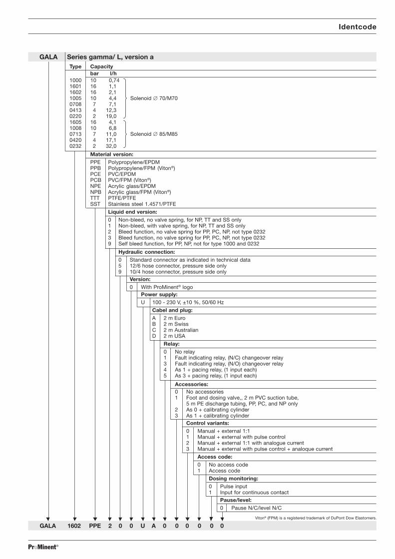
GALA Series gamma/ L, version aType Capacity
bar l/h1000 10 0,741601 16 1,11602 16 2,11005 10 4,40708 7 7,10413 4 12,30220 2 19,01605 16 4,11008 10 6,80713 7 11,00420 4 17,10232 2 32,0
Material version:PPE Polypropylene/EPDMPPB Polypropylene/FPM (Viton®)PCE PVC/EPDMPCB PVC/FPM (Viton®)NPE Acrylic glass/EPDMNPB Acrylic glass/FPM (Viton®)TTT PTFE/PTFESST Stainless steel 1.4571/PTFE
Liquid end version:0 Non-bleed, no valve spring, for NP, TT and SS only1 Non-bleed, with valve spring, for NP, TT and SS only2 Bleed function, no valve spring for PP, PC, NP, not type 02323 Bleed function, no valve spring for PP, PC, NP, not type 02329 Self bleed function, for PP, NP, not for type 1000 and 0232
Hydraulic connection:0 Standard connector as indicated in technical data5 12/6 hose connector, pressure side only9 10/4 hose connector, pressure side only
Version:0 With ProMinent® logo
Power supply:U 100 - 230 V, ±10 %, 50/60 Hz
Cabel and plug:A 2 m EuroB 2 m SwissC 2 m AustralianD 2 m USA
Relay:0 No relay1 Fault indicating relay, (N/C) changeover relay3 Fault indicating relay, (N/O) changeover relay4 As 1 + pacing relay, (1 input each)5 As 3 + pacing relay, (1 input each)
Accessories:0 No accessories1 Foot and dosing valve,, 2 m PVC suction tube,
5 m PE discharge tubing, PP, PC, and NP only2 As 0 + calibrating cylinder3 As 1 + calibrating cylinder
Control variants:0 Manual + external 1:11 Manual + external with pulse control2 Manual + external 1:1 with analogue current3 Manual + external with pulse control + analoque current
Access code:0 No access code1 Access code
Dosing monitoring:0 Pulse input1 Input for continuous contact
Pause/level:0 Pause N/C/level N/C
GALA 1602 PPE 2 0 0 U A 0 0 0 0 0 0
Identcode
Viton® (FPM) is a registered trademark of DuPont Dow Elastomers.
Solenoid � 70/M70
Solenoid � 85/M85

ProMinent®
General User Guidelines
Please read through the following user guidelines. Familiarity with these points ensuresoptimum use of the operating instructions.
On the fold-out page after the title page you will find the overviews “control elements and keyfunctions” and “operating/settings diagrams”.You will find it useful to open out the “control elements and key functions” overview as you readthis instructions manual.
Key points in the text are indicated as follows:
• Enumerated points� Hints
Working guidelines:
GUIDELINES
Guidelines are intended to make your work easier.
Safety guidelines:
WARNING
Describes a potentially dangerous situation. Could result in loss of life orserious injury if preventative measures are not taken.
CAUTION
Describes a potentially dangerous situation. Could result in lesser injuries ordamage to property if preventative measures are not taken.
TAKE CARE
Describes a potentially threatening situation. Could result in damage toproperty if preventative measures are not taken.
The name plate affixed to the title page is identical to that on the gamma/ L pump supplied.This facilitates matching the correct operating instructions manual to the correct pump.
Please quote the identity code and the serial number, which you will find on the name plate, inany subsequent correspondence or when ordering spare parts. This will ensure accurateidentification of the pump type and material version.
General User Guidelines

ProMinent® Page 1
About this pump / Safety
1 About This Pump
The pumps in the ProMinent® gamma/ L pump series are microprocessor controlled solenoiddosing pumps with the following special features:
• The feed rate can be displayed in l/h and/or gal/h, or in strokes/min.
• The stroke rate is continuously adjustable and is displayed in the LCD display.
• Stroke rate adjustment is digitally accurate and is displayed in the LCD display.
• The rated pressure of the gamma/ L can be adapted to individual systems.
• Two pumps can be controlled in different ways via the same standard signal.
• Large, illuminated LCD display
The hydraulic parts of the gamma/ L are identical to those of the Beta®.
2 Safety
Correct use The gamma/ L must be used for liquids only!
The gamma/ L may be used only in compliance with the technical data and specifications givenin the operating instructions!
It is forbidden to use the gamma/ L for any other purpose, or to modify it in any way!
The gamma/ L is not suitable for dosing gases or solids!
The gamma/ L must be used by trained and authorised personnel only!
Safety guidelinesWARNING
• As soon as the gamma/ L is connected to the electricity supply it maycommence pumping!Avoid leakage of hazardous chemicals in this case!If this should occur, then press the STOP/START key or disconnect thegamma/ L from the power supply immediately!
• The gamma/ L cannot be switched to a current-free status! In the event of anelectrical accident, disconnect cable from the mains power supply!
• Disconnect cable from the mains power supply before commencing work onthe gamma/ L!
• Always depressurise liquid end before commencing work on the gamma/ L!
• Empty and rinse out the liquid end before commencing work on the gamma/L after use with hazardous or unknown chemicals!
• Pumps for radioactive materials may not be returned to ProMinent after use!
CAUTION
• It is not permitted to assemble and install ProMinent® dosing pumps withnon-original parts unless these have been checked and recommended byProMinent. It can result in harm to persons and property for which no liabilitywill be accepted!
• When dosing aggressive materials, check the resistance of the pumpmaterials (see ProMinent® resistance list in the product catalogue!)
• Observe applicable national directives during installation!
Sound intensity level The sound intensity level is < 70 dB (A) at maximum stroke, maximum stroke rate, maximumback pressure (water) in accordance with:DIN EN ISO 3744 (Reproducibility 2 Determining Sound Intensity Level)PR DIN EN 12639 (Metering Pump Noise Measurement)DIN 45635-24 (Machine Noise Measurement)

ProMinent®Page 2
Storage, Transport and Unpacking / Device Overview and Control elements
3 Storage, Transport and Unpacking
Transport and store the gamma/ L in the original packaging!
Protect the packed gamma/ L from moisture and the effects of chemicals!
Environmental conditions for storage and transport:
Storage and transport temperature: –10 bis +50 °CHumidity: < 92 % relative humidity
Check that the delivery is complete:
Delivery range • Dosing pump with mains lead• Operating instructions manual with EU conformity declaration• Accessories if applicable
4 Device Overview and Control elements
When reading this section it is helpful to fold out the overview “Control elements and keyfunctions”!
4.1 Device overview
3
3.1
a
d
b
f
g
c
3.2
a
e
b
d
c
1 21 Control unit2 Power end3 Liquid end
Fig. 01
a Backplateb Liquid endc Suction valved Discharge valvee Bleed valvef Coarse/fine bleed valveg Bypass hose nozzle
Fig. 02 Fig. 03

ProMinent® Page 3
Device Overview and Control elements / Function Description
4.2 Control elements
Please acquaint yourself with the gamma/ L control elements with the help of the “controlelements and key functions” overview!
Indicators The LCD display supports the operation and setting of the gamma/ L with a range of indicators:
SetFlowCalibMem
ErrorPauseAuxStop
The indicators are interpreted as follows:
Symbol for P key: The gamma/ L is in settings mode.
Close symbol: In a continuous display: lock (if code has been set).In settings mode: indicates access to code menu.
Stop: The gamma/ L has been stopped using the STOP/START key.
Pause: The gamma/ L has been stopped using the “pause” function(external).
Aux: The gamma/ L is pumping at the auxiliary frequency. In AUXmenu: the gamma/ L is in the AUX menu.
Error: A fault has occurred and the pump has been stopped.
Mem: An additional “memory” function has been set in the “contact”and “batch” operating modes.In CNTCT or BATCH menus (“mem” flashes): the memoryfunction can be set
Calib: The gamma/ L is in the CALIB menu.n a continuous display (“calib” flashes”): more than ± 10 %deviation of stroke rate from value at the moment of calibration.
Flow: The gamma/ L is in the FLOW menu.
Set: The gamma/ L is in the SET menu.
Command symbol: The number of strokes reached is above the maximum value(99999) that can be shown in the LCD display
5 Function Description
Function principle Dosing takes place as follows: the dosing diaphragm is forced into the liquid end; the pressurein the liquid end causes the suction valve to close and the chemical flows out of the liquid endthrough the discharge valve. The dosing diaphragm is then forced back out of the liquid end.The vacuum in the liquid end causes the discharge valve to close and fresh chemical flows intothe suction valve in the liquid end. This concludes one operating cycle.
The dosing diaphragm is driven by an electronically controlled electrical solenoid.
Feed rate The feed rate is determined by the stroke length and the stroke rate.
The stroke length is set between 0 - 100 % using the stroke length adjusting knob. Optimumdosing reproducibility is achieved by setting the stroke length to between 30 - 100 % (SEK type:50 - 100 %)!
The stroke rate is set using the arrow keys (not in “analogue” operating mode) to between0 - 180 strokes/min.
Self-bleed function Pumps with self-bleed function (= SEK types) can operate a prime action even when thedischarge tubing is closed, discharging existing air through a bypass valve. These pumps canrelease gas even during operation, irrespective of the actual operating pressure.
An in-built pressure maintenance valve allows accurate dosing even in depressurised states.

ProMinent®Page 4
Function Description
Operating modes Operating modes are selected using the MODE menu (depending upon identity code, someoperating modes may be absent).
“Analogue” operating mode: (Identity code, control variant: analogue current)
The stroke rate is controlled via an analogue electrical signal via the “external control” terminal.Signal processing is pre-selected at the controller.
“Manual” operating mode: (Identity code, control variant: manual, standard function)
The stroke rate is controlled manually via the controller.
“Contact” operating mode: (Identity code, control variant: external 1:1 / external with pulsecontrol)
This operating mode offers the opportunity to make fine adjustments with small increase/decrease factors. Dosing can be activated by a pulse via the “external control” terminal or by asemiconductor element. With the “pulse control” option it is possible to pre-set a feed quantity(batch) or number of strokes (factor 0.01 to 99.99) via the control unit.
“Batch” operating function: (identity code, control variant, external 1:1 / external with pulsecontrol)
This operating mode offers the option of working with larger transfer factors (up to 65535).Metering can be triggered by pressing the P key or a pulse from the “external control” terminalvia a contact or semiconductor element. A batching quantity or number of strokes can be pre-selected via the control unit.
Functions The following functions can be selected using the SET menu:
“Calibrate” function:
The gamma/ L can be operated in all operating modes including in calibrating mode. Thecorresponding continuous displays can show the actual feed quantity or the feed rate.Calibration is maintained within the stroke frequency range 0 - 180 strokes/ min. Calibration isalso maintained when a stroke frequency is altered up to ± 10 %.
“Pressure level” function:
It is possible to set different pressure levels.
“Auxiliary frequency” function:
It is possible to set a stroke rate in the SET menu, which may be activated via the “externalcontrol” terminal. This auxiliary frequency overrides all other pre-set stroke rate frequencies.
“Flow” function:
Stops the gamma/ L when the flow is insufficient. In the SET menu, the number of failed strokesis entered after which the pump will be turned off.
The following functions are available as standard:
“Float switch” function:
Information on the liquid level in the feed chemical container is transmitted to the gamma/ L.This option requires the installation of a 2-stage float switch. This is connected to the “floatswitch” terminal.
“Pause” function:
The gamma/ L can be stopped by remote control via the “external control” terminal. The “pau-se” function operates only via the “external control” terminal.
The following functions are activated by keystrokes:
“Stop” function:
The gamma/ L can be stopped by pressing the STOP/START key without disconnecting fromthe mains power supply.
.

ProMinent® Page 5
Function Description
“Prime” function:
Priming (short term feed at maximum frequency) is activated by pressing both arrow keys at thesame time.
Optional relay The gamma/ L has two connection options.
“Fault indicating relay” option:
In the event of fault signals, warning signals or float switch activation signals, connects anelectrical circuit to trigger alarm sirens etc. The relay is retrofitted via an aperture in the powerend.
“Fault indicating and pacing relay” option:
Along with the fault indicating relay, the pacing relay produces an electrical impulse for everystroke. The relay is retrofitted via an aperture in the power end.
Function and errorindicators The operating and error status is shown via the three LEDs and the “error” indicator on the LCD
(see also section 12):
LCD indicator If a fault occurs “error” will appear along with an additional fault warning.
LED indicator Operating indicator (green)
This indicator is lit as long as the gamma/ L is operating correctly.
Warning indicator (yellow)
This warning light appears if the gamma/ L electronics detect a situation that could lead to afault, e.g. “liquid levels low 1st stage”.
Warning indicator (red)
This warning light appears if a fault occurs, e.g. “liquid levels low 2nd stage”.
Hierarchy of operating modes, functions and fault statuses
The different operating modes, functions and fault statuses each have a differing effect onwhether and how the gamma/ L functions. These effects are given below:
1. Prime
2. Fault, stop, pause
3. Auxiliary frequency
4. Manual, analogue, contact, batch
to:
1. “Prime” can be activated in any pump status (as long as it is operable)
2. “Fault”, “stop” and “pause” stop all system parts up to “prime”.
3. The stroke rate of the “auxiliary frequency” always overrides the existing operating strokerate.

ProMinent®Page 6
Assembly and Installation
6 Assembly and Installation
WARNING
• The gamma/ L series dosing pumps must be commissioned exactly asdescribed in the operating instructions manual!
• It is not permitted to assemble and install ProMinent® dosing pumps withnon-original parts unless these have been checked and recommended byProMinent.
• Always depressurise tubing before working on the dosing pump. Empty andrinse out the liquid end!
• Never allow the dosing pump to operate when an discharge tube stop tap isclosed ! It may burst!
• Remove all water from liquid end before commissioning or rinse with asuitable cleaning agent if using chemicals that should not come into contactwith water!
• Before unscrewing the control unit disconnect the mains lead from thepower supply!
• Observe applicable national directives during installation!
6.1 Assembling dosing pump
TAKE CARE
• The gamma/ L should be fixed in such a way as to prevent vibration!
• Suction and discharge valve must be upright (bleed valve in self-bleed liquidends)!
• Ensure free access for operation and maintenance!
Assembling dosing pump The base of the dosing pump must be mounted on a firm, horizontal surface.
6.2 Assembling tubing
6.2.1 Installation for non-self bleeding pumps
CAUTION
• Tubing must be free from stress and kinks when fitted!
• When dosing extremely aggressive or hazardous chemicals it is advisable toinstall a bleed valve that feeds back to the container and isolation valves onthe prime and discharge sides.
• In order to ensure connections are fast, use correctly sized clamping ringsand nozzle unions!
• Use only original hoses with specified dimensions and wall-thicknesses!
• Do not exceed maximum permissible priming pressure (see section 14)!
• It is imperative that the maximum permissible operating pressure is notexceeded (see section 14 and appendix documentation)!
GUIDELINE
The tubing should be attached in such a way as to allow lateral detachment of thegamma/ L and the liquid end if necessary!
ProMinent® Page 7
Assembly and Installation
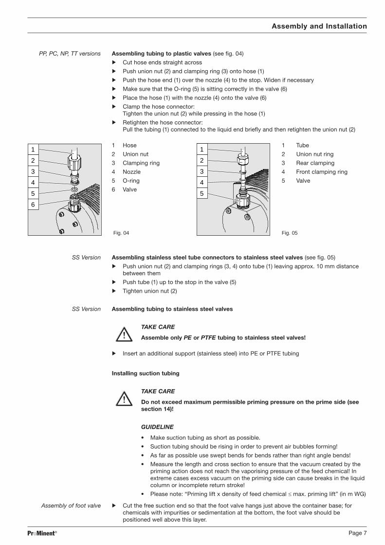
PP, PC, NP, TT versions Assembling tubing to plastic valves (see fig. 04)
S Cut hose ends straight across
S Push union nut (2) and clamping ring (3) onto hose (1)
S Push the hose end (1) over the nozzle (4) to the stop. Widen if necessary
S Make sure that the O-ring (5) is sitting correctly in the valve (6)
S Place the hose (1) with the nozzle (4) onto the valve (6)
S Clamp the hose connector:Tighten the union nut (2) while pressing in the hose (1)
S Retighten the hose connector:Pull the tubing (1) connected to the liquid end briefly and then retighten the union nut (2)
1
2
4
5
6
3
1 Hose1
2
4
5
3
1 Tube
2 Union nut 2 Union nut ring
3 Clamping ring 3 Rear clamping
4 Nozzle 4 Front clamping ring
5 O-ring 5 Valve
6 Valve
Fig. 04 Fig. 05
SS Version Assembling stainless steel tube connectors to stainless steel valves (see fig. 05)
S Push union nut (2) and clamping rings (3, 4) onto tube (1) leaving approx. 10 mm distancebetween them
S Push tube (1) up to the stop in the valve (5)
S Tighten union nut (2)
SS Version Assembling tubing to stainless steel valves
TAKE CARE
Assemble only PE or PTFE tubing to stainless steel valves!
S Insert an additional support (stainless steel) into PE or PTFE tubing
Installing suction tubing
TAKE CARE
Do not exceed maximum permissible priming pressure on the prime side (seesection 14)!
GUIDELINE
• Make suction tubing as short as possible.
• Suction tubing should be rising in order to prevent air bubbles forming!
• As far as possible use swept bends for bends rather than right angle bends!
• Measure the length and cross section to ensure that the vacuum created by thepriming action does not reach the vaporising pressure of the feed chemical! Inextreme cases excess vacuum on the priming side can cause breaks in the liquidcolumn or incomplete return stroke!
• Please note: “Priming lift x density of feed chemical £ max. priming lift” (in m WG)
Assembly of foot valve S Cut the free suction end so that the foot valve hangs just above the container base; forchemicals with impurities or sedimentation at the bottom, the foot valve should bepositioned well above this layer.

ProMinent®Page 8
Assembly and Installation
Installing pressure tubing
TAKE CARE
• The discharge tubing should be laid in such a way as to ensure that thepressure surge of the discharge stroke does not exceed the maximumoperating pressure. As overload protection for the discharge tubing, it isadvisable to fit a relief valve feeding back into the chemical supply container,e.g. a ProMinent® multifunction valve.
• Check that the length and cross section of the tubing are correct!
6.2.2 Installation of self-bleeding pumps
CAUTION
• Observe all installation and safety guidelines for standard pumps!
• Do not exceed tubing cross section, priming lift, priming pressure orviscosity of feed chemical!
In addition to the suction and discharge tubing, a bypass tube should be connected. This isattached to the bleed valve on the upper side of the liquid end (red packing, see fig. 06).
GUIDELINE
The discharge valve is located on the front of the liquid end in the SEK type!
Installation of by-pass tubing
GUIDELINE
When the suction side is primed, at least equal pressure must exist in the bypasstubing!The pump can operate when the bypass is primed and the suction side isdepressurised.
S Place the tube onto the bypass nozzle and/or bleed valve of the self-bleed function liquidend (recommended: flexible 6x4 PVC hose)
S Push the free end of the tube back into the dosing container
S Cut the bypass tube so that it does not enter the feed chemical.
Bleed valve for the bypass tube to the supplycontainer, 6/4 mm
Discharge valve for discharge tubing to injectionpoint, 6/4 - 12/9 mm
Suction valve for suction tubing in supplycontainer, 6/4 - 12/9 mm
Fig. 06

ProMinent® Page 9
Assembly and Installation
6.3 Electrical installation
WARNING
• Installation must be carried out by a trained engineer!
• Disconnect gamma/ L from mains power supply during installation!
• Observe applicable national directives when installing the dosing pumps!
• When connecting with parallel inductive power consumers a switchcontact must be fitted, e.g. relay or contactor!
Connectionto mains power supply Connect the gamma/ L to the mains power supply using the mains lead
Parallel connection toinductive power consumers If the gamma/ L is connected to the mains in parallel with inductive power consumers
(e.g. solenoid valve, motor) they must be electrically isolated. This will avoid damage causedby induction and voltage surges when switching off.
S Fit individual contacts for the gamma/ L and supply power via auxiliary contactor or relay.If this is not possible, then:
S Connect a varistor in parallel (order number 710912) or an RC circuit, 0.22 mF/220 W(order number 710802).
Power element(in base of pump)
1
PEL1N
2
4
5
3
Fig. 07
1 Mains terminal2 Relay circuit terminal3 Fuse4 Solenoid earth lead terminal5 Solenoid terminal
“External control”terminal The “external control” terminal is a five pin in-built terminal. It is compatible with the two and
four core cables used previously.The “auxiliary frequency” function is only available with a five core cable.

ProMinent®Page 10
Assembly and Installation
gamma/ L configuration Electrical interface for “external contact” - “pause” - “auxiliary frequency”:
• Voltage when contacts open: approx. 5 V• Input resistance: 10 kW• Control: voltage free contact (load: 0.5 mA at 5 V),
or: Semiconductor switch (residual voltage < 0.7 V)
• Maximum pulse frequency: 25 pulses/s• Required pulse duration: ³ 20 ms
Electrical interface for “external analogue":
• Input load resistance: approx. 120 W• Maximum current at input: 50 mA
gamma/ L configuration
1
54
2
3
Pin Function 2 core cable 4 core cable 5 core cable
Pin 1 Pause Jumped at pin 4 Brown BrownPin 2 External contact Brown White WhitePin 3 External analogue – Blue BluePin 4 Earth White Black BlackPin 5 Auxiliary frequency – – Grey
Fig. 08
Plug configuration
2
45
1
3
“Pause” function
The gamma/ L is not operating when• The cable is connected and pins 1 and 4 are free.
The gamma/ L is operating when• The cable is connected and pins 1 and 4 are connected.
• There is no cable connected (pin 1 is free).
Fig. 09
“Contact” und “Batch” operating modes
One or more discharge strokes are triggered when pin 2 and pin 4 are connected to one anotherfor at least 20 ms.Otherwise, pin 1 and pin 4 must be connected.
“Analogue” operating mode
The stroke frequency of the gamma/ L is controlled via an electrical signal. The electrical signalis applied between pins 3 and 4.Otherwise, pin 1 and pin 4 must be connected.
“Auxiliary frequency” function
The gamma/ L runs at a pre-set stroke rate when pin 5 and pin 4 are connected to one another.Otherwise, pin 1 and pin 4 must be connected.
The factory setting for this function is 180 strokes.
GUIDELINE
For function and operating mode hierarchy, see section 5!

ProMinent® Page 11
Assembly and Installation
Connecting two gamma/ L pumps in series
Connect two gamma/ L pumps in series as follows if you wish to control both via an electricalsignal in the “analogue” operating mode (see section 7.4.2):
blue
brown
black
blue
brown
blackgray
white
gray
white
+ power source –
Fig. 10
“Float switch” terminal Optional fitting of a 2-stage float switch with prior warning and limit switch capacity.
gamma/ L configuration
3
21
Electrical interface:
• Voltage when contacts open: approx. +5 V
• Input resistance: 10 kW• Controller: voltage free contact (load: 0.5 mA at + 5V),
or: semiconductor switch (residual voltage < 0.7 V)
Fig. 11
Plug configuration
3
12
Function 3 core cable
Pin 1 Earth black
Pin 2 Minimum prior warning blue
Pin 3 Minimum limit switch brown
Fig. 12
“Dosing monitor” terminal Optional connection of dosing monitor.
gamma/ L configuration
1
4
2
3
Electrical interface:
• Voltage when contacts open: approx. +5 V
• Input resistance: 10 kW• Controller: voltage free contact (load: 0.5 mA at + 5V)
Fig. 13
Plug configuration
1
4
2
3
Function 4 core cable
Pin 1 Power supply (5V) brown
Pin 2 Encoding white
Pin 3 Response blue
Pin 4 Earth black
Fig. 14

ProMinent®Page 12
Assembly and Installation
Relay
“Fault indicating relay” output A fault indicating relay may be ordered optionally. It is used as the signal output when a pump
fault has been detected and to indicate the prior warning signal “liquid level low, stage 1” andthe fault signal “liquid level low, stage 2”.Allocation of signal types to “N/O” and “N/C” relay states is selected on the basis of the identitycode descriptors.The relay can be retrofitted and is ready to operate after inserting the relay component (seesection 6.4).
The gamma/ L is delivered ex works with default settings for a N/C relay. If an alternative switchfunction is required the gamma/ L can be reprogrammed at ProMinent.
Electrical interface • Contact load: 250 V/2 A 50/60 Hz• Operating life: > 200.000 switch cycles
“Fault indicating relay andpacing relay” output A fault indicating relay and pacing relay output may be ordered optionally. The pacing relay
output is electrically isolated via an optical coupler with a semiconductor switch. The secondswitch is a relay as for the “fault indicating relay” variant.The fault indicating / pacing relay can be retrofitted (see section 6.4).
The gamma/ L is delivered ex works with default settings for a N/C fault indicating relay and aN/O pacing relay. If an alternative switch function is required the gamma/ L can bereprogrammed at ProMinent.
Electrical interface For semiconductor switch For relay output
• Residual voltage: < 0,4 Volt at IC = 1 mA • Contact load:• Maximum voltage: < 100 mA 24 V/100 mA 50/60 Hz• Maximum current: 24 V/DC • Operating life:• Pacing relay pulse duration: approx. 100 ms > 200.000 switch cycles
Relay cable contact configuration
“Fault indicating relay” option VDE cable CSA cable Contact
white white NO (normally open)green red NC (normally closed)brown black C (common)
“Fault indicating relayand pacing relay” option VDE cable Contact Relay
yellow NO (normally open) Fault indicating relaygreen C (common) Fault indicating relaywhite NO (normally open) Pacing relaybrown C (common) Pacing relay
6.4 Retrofitting relays
Delivery range:
1 relay circuit set with 2 screw fasteners1 relay cable set with socket1 seal
Press-out relay openingWARNING
Disconnect gamma/ L from the mains power supply and rinse liquid end beforecommencing work (see section 13)!
TAKE CARE
When preparing the opening, ensure that the punch is not forced through theentire pump base!Pump circuits may become damaged.

ProMinent® Page 13
Assembly and Installation
S Place the gamma/ L on a firm surface with the relay opening press-out section at the top(see fig. 15:a)
S Place a punch (dia. 8-15 mm) in the centre of the relay opening press-out section , andstrike briefly and sharply with a hammer (approx. 250 g)
S If necessary clean up the edges of the opening
S Remove the pressed out section from the gamma/ L
a
a
Fig. 15 Fig. 16
Inserting the relay component S Hold the relay component with your right hand gripping the left and right hand edges of therelay cover, and tilt the front end slightly to the left (see fig. 17)
S Push the relay component through the relay opening, holding the upper corner of the loweredge against the guide rail on the pump base, until the contact of the relay component hasreached the controller contact. (See fig. 18: test: can you still move the end of the circuitback and forth?)
S Gently push the relay component right into the opening.
S Screw the relay cover firmly onto the housing using the screws provided.
S Insert the relay cable plug seal into the relay cover and screw on the plug (see fig. 19)
b
Fig. 17 Fig. 18 Fig. 19

ProMinent®Page 14
Settings
7 Settings
GUIDELINE
• Open out the fold-out page following the title page fully! There you will find theoverviews “control elements and key functions” and “operating settings dia-gram”.
• If no keys are pressed within a period of 1 minute, the gamma/ L will return to acontinuous display.
Basic information for setting up the gamma/ L
P
P
P
3 s P 3 s
continuous display
sserpSet 1pSet
= flashes
= Settings option
Confirm entries Press the P key briefly;You will automatically move to the next menu option or to a continuous display.
Exit menu option without confirming Press the P key for 3 s:
The entry is cancelled and you will return to a continuous display.
i 1x2x
2345
23452345 2345
iP
Incremental changeIof a value Press the i key 1x;
you can toggle between altering the digits of a value (“change individual digits” = standard) orincremental alteration of a value (“change a figure”).
Change adjustable values Press UP or DOWN arrow key;The flashing digit or figure will start to increase or decrease incrementally.
Confirm adjustable values For “change individual digits”: confirm each digit using the p key. When the last digit has beenconfirmed you will automatically move to the next menu option or to a continuous display.
For “change a figure”; press the P key 1x; you will simultaneously move to the next menu optionor to a continuous display.
Correct wrongly set digits Press the i key 2x;you will go back to the first digit.
ProMinent® Page 15
Settings
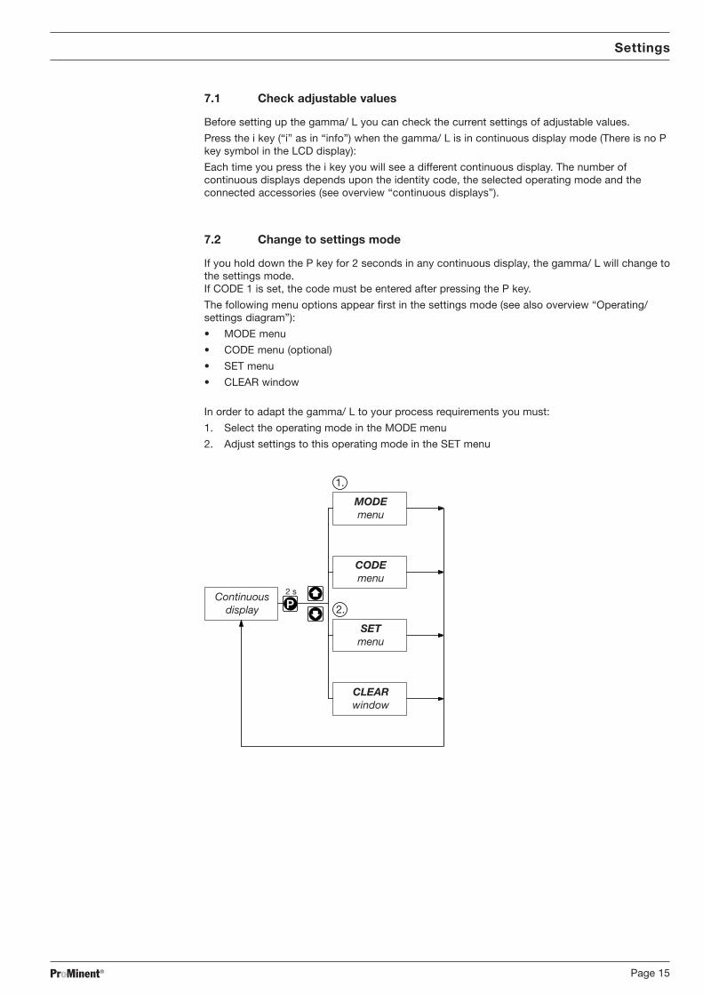
7.1 Check adjustable values
Before setting up the gamma/ L you can check the current settings of adjustable values.
Press the i key (“i” as in “info”) when the gamma/ L is in continuous display mode (There is no Pkey symbol in the LCD display):
Each time you press the i key you will see a different continuous display. The number ofcontinuous displays depends upon the identity code, the selected operating mode and theconnected accessories (see overview “continuous displays”).
7.2 Change to settings mode
If you hold down the P key for 2 seconds in any continuous display, the gamma/ L will change tothe settings mode.If CODE 1 is set, the code must be entered after pressing the P key.
The following menu options appear first in the settings mode (see also overview “Operating/settings diagram”):
• MODE menu
• CODE menu (optional)
• SET menu
• CLEAR window
In order to adapt the gamma/ L to your process requirements you must:
1. Select the operating mode in the MODE menu
2. Adjust settings to this operating mode in the SET menu
P2 sContinuous
display
MODEmenu
SETmenu
CODEmenu
CLEARwindow
1.
2.

ProMinent®Page 16
Settings
7.3 Select operating mode (MODE menu)
The following operating modes are selected via the MODE menu (depending upon identity code,some operating modes may be absent):
• Manual: for operation by hand(Identity code, control variant: manual, standard option)
• Analogue: for electronic control(Identity code, control variant: analogue current)
• Contact: for contact operation(Identity code, control variant: external 1:1 / external with pulse control)
• Batch: for batch operation(Identity code, control variant: external with pulse control)
P P
Continuous display
edomBatchContactManualAnalog
edomAnalog
7.4 Settings for operating mode (SET menu)
In the SET menu you can adjust various settings depending upon the selected operating mode.
The following programmable function settings menus appear in all operating modes:
• Calibrate (CALIB menu)
• Pressure levels (PRESS menu)
• Auxiliary frequency (AUX menu)
• Flow (FLOW menu, available only if flow monitor is connected)
See also section 7.5!
Further settings menus depend upon the selected operating mode.
7.4.1 Settings for “manual” operating mode
There are no other settings menus in the overall SET menu for the “manual” operating modeapart from those described in 7.5.
7.4.2 Settings for “analogue” operating mode (ANALG menu)
In addition to those settings menus described in 7.5, there is an additional ANALG menu in theoverall SET menu for the “analogue” operating mode.
The stroke rate is controlled by an analogue electrical signal via the “external control” terminal.
You can select three signal-processing methods:
• 0 - 20 mA: at 0 mA the gamma/ L does not operateat 20 mA the gamma/ L operates at 180 strokes/min.Between these two extremes the stroke rate is proportional to the electricalsignal.
PP P
Continuous display
glanaSet 02o mASet
Analog
tes

ProMinent® Page 17
Settings
• 4 - 20 mA: at 4 mA the gamma/ L does not operateat 20 mA the gamma/ L operates at 180 strokes/min.Between these two extremes the stroke rate is proportional to the electricalsignal.For signals of below 3.8 mA a fault will be detected and the gamma/ L will stop(e.g. cable break).
• Curve: In the “curve” processing mode you can programme the gamma/ L ratios.There are 3 options available:
• = straight line
• = lower band
• = upper band
P P
P P P
P P PP
Continuousdisplay
glanaSet evrucSet
Analog
noreSet
Analog
Set
Analog
04o1iAnalog
mASet
0212fAnalog
Freq.
Set
06o1fAnalog
Freq.
Set 0612iAnalog
mASet
tes
Straight line:
The following symbol appears in the LCD display: .You can enter any stroke frequency ratio for the gamma/ L in proportion to the electricalsignal. You must enter two points P1 (I1, F1) and P2 (I2, F2). F1 is the stroke rate at whichthe pump should operate at current I1: the straight line and the ratio are fixed accordingly:
I [mA]I 1 I 2
F1
F2
Fmax
0 20
P1
P2
Fig. 20
GUIDELINE
Draw a diagram like the one above - with values for (I1, F1) and (I2, F2) - in order toset the gamma/ L to your required stroke rate !
ProMinent®Page 18
Settings
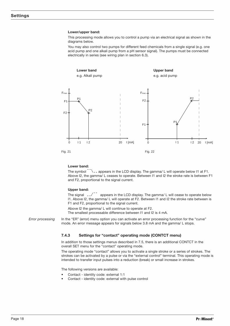
Lower/upper band:
This processing mode allows you to control a pump via an electrical signal as shown in thediagrams below.
You may also control two pumps for different feed chemicals from a single signal (e.g. oneacid pump and one alkali pump from a pH sensor signal). The pumps must be connectedelectrically in series (see wiring plan in section 6.3).
Lower band Upper band
e.g. Alkali pump e.g. acid pump
I [mA]I 1 I 2
F2
F1
0 20
P1
P2
Fmax
I [mA]I 1 I 2
F1
0 20
P1
P2 F2
Fmax
Fig. 21 Fig. 22
Lower band:
The symbol appears in the LCD display. The gamma/ L will operate below I1 at F1.Above I2, the gamma/ L ceases to operate. Between I1 and I2 the stroke rate is between F1and F2, proportional to the signal current.
Upper band:
The signal appears in the LCD display. The gamma/ L will cease to operate belowI1. Above I2, the gamma/ L will operate at F2. Between I1 and I2 the stroke rate between isF1 and F2, proportional to the signal current.
Above I2 the gamma/ L will continue to operate at F2.The smallest processable difference between I1 and I2 is 4 mA.
Error processing In the “ER” (error) menu option you can activate an error processing function for the “curve”mode. An error message appears for signals below 3.8 mA and the gamma/ L stops.
7.4.3 Settings for “contact” operating mode (CONTCT menu)
In addition to those settings menus described in 7.5, there is an additional CONTCT in theoverall SET menu for the “contact” operating mode.
The operating mode “contact” allows you to activate a single stroke or a series of strokes. Thestrokes can be activated by a pulse or via the “external control” terminal. This operating mode isintended to transfer input pulses into a reduction (break) or small increase in strokes.
The following versions are available:
• Contact - identity code: external 1:1• Contact - identity code: external with pulse control

ProMinent® Page 19
Settings
Contact – identity code: external 1:1
In the “contact - identity code: external 1:1” version the gamma/ L makes precisely 1 stroke perpulse (identity code: external 1:1). No entry possible.
Contact – identity code: external with pulse control
In the “contact - identity code: external with external pulse control” you can enter the number ofpulses after which a stroke should be carried out. “Contact - identity code: external withexternal pulse control” is intended for small dosing quantities.
P PPP
Continuous display
tctncSet noSet
MemContact
0Set
MemContact
021tes
The number of strokes per pulse depends upon the factor, which you can enter. This allows youto vary to a certain extent the input pulses by a factor of 1.01 to 99.99 and/or reduce by a factorof 0.01 to 0.99:
“Number of strokes activated = factor x number of input pulses”
Examples Factor Pulse (sequential) Stroke number (sequential)
Increase 1 1 12 1 2
25 1 259999 1 99991.50 1 1.5 (1 / 2)1.25 1 1.25 (1 / 1 / 1 / 2)
Reduction 1 1 10.50 2 10.10 10 10.01 100 10.25 4 10.40 2.5 (3 / 2) (1 / 1)0.75 1.33 (2 / 1 / 1) (1 / 1 / 1)
Explanation of increaseAt a factor of 1 For every 1 pulse, 1 stroke is activatedAt a factor of 2 For every 1 pulse, 2 strokes are activatedAt a factor of 25 For every 1 pulse, 25 strokes are activated
Explanation of decreaseAt a factor of 1 After 1 pulse, 1 stroke is activatedAt a factor of 0.5 After 2 pulses, 1 stroke is activatedAt a factor of 0.1 After 10 pulses, 1 stroke is activatedAt a factor of 0.75 After 2 pulses, 1 stroke is activated,
then after 1 pulse, 1 stroke is activated,then after 2 pulses, 1 stroke is activated etc.
GUIDELINE
If a remainder occurs when the factor is processed, the gamma/ L counts up theremainder values. When the sum reaches or exceeds “1” the gamma/ L will activatea stroke. This ensures that the stroke number corresponds exactly to the factorthroughout the dosing operation .

ProMinent®Page 20
Settings
The number of input pulses which have not been processed are stored by the gamma/ L in thestroke memory. When the STOP/START key is pressed or the “pause” function is activated, thestroke memory is deleted (this can be avoided using the “memory” extension function, seebelow).
The “contact - identity code: external with pulse control” version allows optimum adaptation ofthe gamma/ L, in conjunction with e.g. water contact meters, to any process.
“Memory” extension function
The “memory” extension function can be optionally activated (“mem” appears in the LCDdisplay). The remaining strokes will not then be deleted when the STOP/START key is pressed orthe “pause” function is activated.
7.4.4 Settings for “batch” operating mode (BATCH menu)
In addition to those settings menus described in 7.5, there is an additional BATCH menu in theoverall SET menu for the “batch” operating mode.
P P PP
Continuous display
hctabSet noSet
MemBatch
02451Set
MemBatch
Ltes
The “batch” operating mode is a variant of the “contact” operating mode (see 7.4.3).You can pre-select a stroke number (no breaks, whole numbers only) as well as a feed quantity(batch). To switch between entries for “stroke number” and “feed quantity” press the i key 1x inthe corresponding menu option (see also overview “Operating / settings diagram”, fold-outpage).The “batch” operating mode is intended for large dosing quantities.The number of input pulses which have not been processed are stored by the gamma/ L in thestroke memory. When the STOP/START key is pressed or the “pause” function is activated, thestroke memory is deleted (this can be avoided using the “memory” extension function, seebelow).
“Memory” extension function
The “memory” extension function can be optionally activated (“mem” appears in the LCDdisplay). The remaining strokes will not then be deleted when the STOP/START key is pressed orthe “pause” function is activated.

ProMinent® Page 21
Settings
7.5 Settings for programmable functions (SET menu)
The following programmable function settings menus appear in all operating modes:
• Calibrate (CALIB menu)
• Pressure levels (PRESS menu)
• Auxiliary frequency (AUX menu)
• Flow (FLOW menu, available only if flow monitor is connected)
7.5.1 Settings for “calibration” function (CALIB menu)
P P
P P PP
Continuous display
bilacSet noSet
Calib
tratsSet
Calib
tinu LSet0 LSet
Calib
2324
tes
Set
CalibN002
The gamma/ L can also run in calibration mode. The corresponding continuous displays showthe current dosing quantities or the feed rate.
Calibration is maintained when a stroke rate is altered up to ± 10 %. If the stroke rate is alteredmore than ± 10 % the yellow warning light is lit, the continuous display flashes and the flashingmessage “calib” appears.
GUIDELINE
• Do not go below 30 % stroke length (SEK type: 50%).This will significantly affect accuracy of calibration.
• Calibration becomes increasingly accurate the more strokes made by thegamma/ L during calibration (recommended: at least 200 strokes).
WARNING
• If using a hazardous feed chemical, the following setting instructions ensureadequate safety precautions have been taken!
Calibration S Insert the suction tube into a measuring cylinder containing the feed chemical - thedischarge tubing must also be correctly installed (operating pressure,…!)
S Suck up the feed chemical (press both arrow keys at the same time) when the suction tubeis empty
S Note the liquid level in the measuring cylinder and the stroke length
S Select the CALIB menu and go the first menu option using the P key
S Select “ON” using an arrow key and change to the next menu option using the P key
S To commence calibration, press the P key. The gamma/ L starts to pump and displays thenumber of strokes (“STOP” appears at regular intervals)
S After a sufficient number of strokes, stop the gamma/ L with the P key
S Calculate the dosed quantity (difference between the original quantity and the quantityremaining)
S Enter this quantity in the menu and then go to the next menu option using the P key
S Select the unit (“L” or “gal”) in the “UNIT” menu with an arrow key
The gamma/ L is calibrated.The corresponding continuous displays show the calibrated values.The total stroke number and total litres are set during calibration to “0”.

ProMinent®Page 22
Settings
7.5.2 Settings for the “pressure levels” function (PRESS menu)
P PP
Continuous display
sserpSet 1pSettes
The programmable function “pressure levels” is used to reduce the rated pressure of thegamma/ L.
CAUTION
• The rated pressure can be considerably exceeded at stroke lengths of below100 %! The rated pressure relates to a stroke length of 100 %.
• If another liquid end size is installed the pump must be reprogrammed onfactory premises!
• Select as large a rated pressure as required and as small as possible! Thiswill increase system safety (reduces the risk of the tubing bursting whenblocked)! This also protects the diaphragm and saves electricity.
GUIDELINE
If installing another liquid end size the pump must be reprogrammed on factorypremises.
The following rated pressures can be selected for these liquid end sizes (rated pressure in bar):
ezisdnediuqiL 1levelerusserP 2levelerusserP 3levelerusserP 4levelerusserP
5061,2061,1061 4 7 01 61
8001,5001,0001 4 7 01
3170,8070 4 7
No adjustments can be made for pump types 0413, 0420, 0220, 0232.
7.5.3 Settings for “auxiliary frequency” function (AUX menu)
P PP
Continuous display
xuaSet 0Freq.
Set
Aux
58tes
The programmable function “auxiliary frequency” allows switching to a different strokefrequency, which can be set in the AUX menu. It can be activated via the “external control”terminal. When the auxiliary frequency is activated, “aux” appears in the LCD display.
This auxiliary frequency overrides the current stroke frequency set for the selected operatingmode.

ProMinent® Page 23
Settings
7.5.4 Settings for the “flow” function (FLOW menu)
P P PP
Continuous display
wolfSet noSetFlow 800Set
Flowtes
The flow menu only appears when a dosing monitor is connected to the “dosing monitor”terminal. This dosing monitor registers each discharge stroke of the gamma/ L at the dischargeconnector and transmits it back to the gamma/ L. If this response transmission is seriallyomitted for a period set in the FLOW menu (due to failure or below-minimum dosing) thegamma/ L stops.
7.6 Setting code (CODE menu)
The code menu is used to select whether you want to prevent access to parts of the settingsoptions.
P P P
Continuous display
edoc 1edoc 2345
In the first menu option you can choose CODE 1 or CODE 2 (both use the same number).
• Select CODE 1 to prevent access to the settings mode (➀ in the overview “Operating /settings diagram”, fold-out page). In the next menu option, enter the number you wish touse as the code.
• Select CODE 2 to prevent access to the settings options for directly alterable values in thecontinuous displays (➁ in the overview “Operating / settings diagram”, fold-out page). In thenext menu option, enter the number you wish to use as the code.
• Select NONE to remove a pre-set security lock.
7.7 Cancel total stroke number or total litres (CLEAR window)
In the CLEAR window you can delete the stored total stroke number and simultaneously the to-tal litres (= set to “0”). You may then press the P key briefly to exit this window.
The values displayed are counted incrementally from the point of commissioning the pump, orfrom the last delete action.
P
Continuous display
raelc LN

ProMinent®Page 24
Commissioning
8 Commissioning
WARNING
• Protect yourself from contact with hazardous feed chemicals!
• Remove all water from liquid end before commissioning or rinse out with asuitable material if using chemicals that should not come into contact withwater! (Proceed as described below. The liquid end may contain water leftover from factory testing.)
• After long periods out of commission the gamma/ L is not guaranteed tometer absolutely reliably, as feed chemicals in the valves and diaphragm cancrystallise! Check valves and diaphragm regularly (see section 10)!
• Check the seals of the pump connections and connectors.
• Check whether coarse or fine bleed vent is closed (see also fine bleedfunction).
GUIDELINE
• Set stroke length only while pump is running!
• The gamma/ L should prime at 100 % stroke length as the suction lift isdependent upon lift volume when the liquid end is empty. If the gamma/ L isrequired to prime at less than 100 % stroke length, and fails to do so, then selecta correspondingly smaller suction lift.
• SEK type: priming capacity is diminished if discharge takes place againstpressure!
• Retighten screws in liquid end after 24 hours (see section 10)!
Removing water fromliquid end When using with chemicals that should not come into contact with water:
S Turn the pump so that the discharge connector is pointing downwards.
S Allow water to run out of the liquid end.
S Rinse the suction connector from above with a suitable material.
Filling liquid endWARNING
Protect yourself from contact with hazardous feed chemicals!
For liquid ends without coarse/fine bleed function:
S Connect suction tubing, but not discharge tubing, to liquid end
S Switch on the gamma/ L and allow to run at maximum stroke length and stroke rate, untilthe liquid end is full and free from air bubbles (a little feed chemical will seep out of thedischarge valve)
S Switch off the gamma/ L
S Connect discharge tubing to liquid end
The gamma/ L is ready to operate.
For liquid ends with coarse/fine bleed function:
S Connect suction and discharge tubing to liquid end
S Connect bypass tubing
S Open the bleed valve by rotating the knob on the top anticlockwise. Opens access to thebypass tubing for coarse bleed function.
S Switch on the gamma/ L and allow to run at maximum stroke length and stroke rate, untilthe liquid end is full and free from air bubbles (the feed chemical is visible in the bypass anddischarge tubing)
S Close the bleed valve (turn clockwise)
S Switch off the gamma/ L
The gamma/ L is ready to operate.

ProMinent® Page 25
Commissioning
GUIDELINE
• For gaseous chemicals there must be a continuous partial flow back to the supplycontainer. The return flow quantity should be approx. 20 % of the feed quantity.
• The feed chemicals should be non-viscous and free from suspended particles.
• The bypass tubing should end above the liquid level in the supply container. Thefine bleed valve then acts as a vacuum breaker which prevents the possibility of avacuum in the discharge tubing causing the container to be emptied.
Fine bleed function
When metering slightly gaseous chemicals the liquid end can be continuously de-aerated via thefine bleed vent, if a coarse/fine bleed vent is present.
Open fine bleed vent (see fig. 23):
S Pull off the cap (a) from the coarse/fine bleed vent (b).
S Turn the screw (c) in the coarse/fine bleed vent approx. 1 turn anticlockwise with ascrewdriver.
c
a
1.
2.
b
Fig. 23
For self-bleed dosing pumps (SEK type):
GUIDELINE
On this liquid end the discharge connector is horizontal - the bleed valve is at thetop! (The bleed connector is identified on delivery with a red collar!)
S Connect the suction and discharge tubing to the liquid end
S Connect the bypass tubing to the liquid end
S Switch on the gamma/ L and allow to run at maximum stroke length and stroke rate until theliquid end is full and free from air bubbles (the feed chemical is visible in the bypass anddischarge tubing)
S Switch off the gamma/ L
The gamma/ L is ready to operate.
8.1 Precision dosing settings
GUIDELINE
• For highly viscous and gaseous chemicals select a large stroke length and a lowstroke rate!
• For good mixing action, select a low stroke length and high stroke rate!
• For precision dosing, set stroke length higher than 30 % (SEK type: higher than50 %)!

ProMinent®Page 26
Commissioning / Operating
8.2 Diagrams for setting feed capacity
General
S Open out the page showing the diagram of your pump type (see appendix).
S Calculate the correction factor. Mark the operating pressure for your application in the dia-gram “correction factor depending upon operating pressure”.
S Trace a line from this value vertically up to the curve and then horizontally left. Read off thecorrection factor.
S Divide the required feed rate by the correction factor determined as above. Mark this value(l/h) on the “l/h” axis in the diagram “feed rate depending upon stroke length and strokerate”.
S Trace a line horizontally from this value to the left. Trace a line from the intersection with thestraight line for the adjustable stroke frequencies vertically downwards to the “strokelength” axis.
S Set the gamma/ L to one of the stroke frequencies determined in this way, and thecorresponding stroke length.
The measurements for determining the feed rate for the following diagrams were carried outusing water and the correction factor was determined at a 70 % stroke length. Distribution ofthe feed rate across all material versions: -5 to +15 %.
9 Operating
This section describes all operating options available to you when the gamma/ L is incontinuous display mode (no P key symbol in the LCD display).
GUIDELINE
• Open out the fold-out page following the title page fully! There you will find theoverviews “control elements and key functions” and “operating settings dia-gram”.
• Look at the overview “continuous displays”. This page shows you which displaysare available in which operating mode, and which values are directly alterable inthe corresponding continuous displays.
9.1 Manual operation
Set stroke length Stroke length is continually adjustable within a range of 0 - 100 %. The recommended strokelength range, which will practically guarantee technical reproducibility, is 30 - 100 % (SEK type:50 - 100 %).The following operating options are available via the different keys (see also figure on the nextpage):
Stop/Start gamma/ L To stop gamma/ L: press STOP/START key.To start gamma/ L: press STOP/START key.
Start batch Press the P key briefly in “batch” operating mode.
Load factory settings Press the P key for 15 s to load factory calibration settings!Current settings will be deleted.
Change to settings mode WeIf you press the P key for 2 s in any continuous display the gamma/ L will change to settingsmode (see section 7).If CODE 1 is set, the code must be entered after pressing the P key.
Check adjustable values Each time you press the i key you will see a different continuous display. The number ofcontinuous displays depends upon the identity code, the selected operating mode and theconnected accessories.
Change directly alterable values To change a value (see below) directly in the corresponding continuous display, press one of the
arrow keys until “set” appears in the LCD display. The delay has been programmed in to preventinadvertent changing of values.If CODE 2 has been set, this code must be entered after pressing the arrow key.Directly alterable values are as follows:

ProMinent® Page 27
Operating
Stroke rate In “manual”, “contact” and “batch” operating modes:The stroke rate can be altered in the “stroke rate” display.
Feed rate In “manual” operating modeThe feed rate can be altered in the “feed rate” display.
Factor The factor is the number of strokes activated by an external pulse or a press of the P key (in“batch” mode only).
In “contact” and “batch” operating modes:
You can alter the factor from the “remaining strokes” display.
The gamma/ L returns to the original continuous display a few seconds after the factor has beenreset.
Batch size In “batch” operating mode:The batch size can by changed from the “batch size/remaining litres” display.The gamma/ L returns to the original continuous display a few seconds after the batch size hasbeen reset.
Priming The “priming” function is activated by pressing both arrow keys at the same time.
Cancel error Error messages are cancelled by pressing the P key briefly.
Settingsmode
P
P
P
i
STOPSTART
Continuous display
2 s
Stopp/start pump
Change directly alterable values
= Security lock (CODE 1)
= Security lock (CODE 2)
Prime
Start batch (in "batch" operating mode only)
Cancel error
Check adjustable values
2
2
1
1
9.2 Remote control
It is possible to control the gamma/ L remotely via a signal cable (see section 6.3 and section 7and appendix documentation).

ProMinent®Page 28
Maintenance / Repairs
10 Maintenance
Maintenance intervals • Every quarter, when subject to normal usage (continuous operation - approx. 30 % )• Shorter intervals when subject to heavier usage (e.g. continuous operation)
Maintenance actions Standard liquid ends:S Check the diaphragm for damage (see section 11)S Check chemical seepage at vent holeS Check that the discharge tubing is connected firmly to the liquid endS Check that discharge and suction valves are firmly fixedS Check that the liquid end is generally watertight (especially vent hole! See fig. 24)S Check for correct feed: run the gamma/ L run for a short period (press both arrow keys
together)S Check electrical connections for wearS Check that liquid end screws are fastened tightly (on coarse/fine bleeding versions, first
remove knob and cover
Screw fastening torque:
Liquid end dia. 70 mm: 2,5 to 3 NmLiquid end dia. 90 mm and dia. 100 mm: 4,5 to 5 Nm
GUIDELINE
• For PP liquid end, check fastening torque every quarter!
Additionally, for liquid ends with coarse/fine bleed function and SEK type:
• Check that the bypass tubing is connected firmly to the liquid end• Check that the bleed valve is firmly fixed in place• Examine the discharge and bypass tubing for kinks• Check that the coarse/fine bleed function is working correctly
Fig. 24 Vent hole
11 Repairs
GUIDELINE
Repair work that may be carried out by authorised personnel only, or on factorypremises:
• Replacement of damaged mains cables• Replacement of fuses and electronic controller.
Please contact your nearest ProMinent branch or representative!
When sending the pump for repair make sure it is clean and that the liquid end hasbeen thoroughly rinsed out (see section 13)! If, despite careful emptying andcleaning, safety precautions are still required for handling the gamma/ L, thenecessary information must be entered in the safety declaration!The safety declaration is a component of the inspection/repair order.An inspection or repair can only be carried out when a safety declaration has beencorrectly and completely filled out by an authorised and qualified member of stafffrom the company operating the pump.
A form is included in the appendix.

ProMinent® Page 29
Repairs
WARNING
Pumps used for radioactive materials cannot be returned to ProMinent afteruse! They will not be accepted by ProMinent!
Repairs: These should only be carried out by qualified personnel (in accordance with Safetysection):
• Cleaning the valve• Changing the diaphragm
WARNING
• Always take suitable precautions when using hazardous chemicals!
• Ensure equipment is de-pressurised
Cleaning the discharge valve (PP, PC, NP) for types 1000, 1005, 1605, 1601, 1602
GUIDELINE
• Discharge and suction valves are different! Dismantle one after the other toavoid confusion.
• Only use new parts, which fit your valve (in shape and chemical resistance)!
• The pump must be reset after replacing a valve.
S Loosen the hose.
S Unscrew the discharge valve from the liquid end and rinse thoroughly.
S Remove the O-ring from the liquid end with a small screw driver.
S Insert an Allen key or similar into the smaller hole of the pressure connector and push outthe valve inserts.
S Remove the valve seats with a small screwdriver and allow the valve balls to drop out.
S Clean all parts
S Drop the valve balls into the valve seats and push on the valve inserts
S Press the valve seats into the pressure connector with their smaller hole in the direction ofthe flow (see direction of arrows on the fluting on the pressure connector)
S Insert the O-ring into the liquid end
S Screw the valve in as far as it will go
S Secure the hose
Fig. 25
Cleaning the suction valve (PP, PC, NP) for types 1000, 1005, 1605, 1601, 1602
Dismantling, cleaning and reassembly of the suction valve is practically the same as for adischarge valve.
Take care however that:
• both valve inserts are actually identical
• an additional spacer is found under the valve inserts
• in the liquid end a shaped seal is used instead of an O-ring
• the flow direction of the suction connection is reversed as for the pressure connector.
Fig. 26

ProMinent®Page 30
Repairs
Cleaning the discharge valve (PP, PC, NP) for types 0708, 1008, 0220, 0420, 0413, 0713, 0232
GUIDELINE
• Discharge and suction valves are different! Dismantle one after the other to avoidconfusion!
• Only use new parts, which fit your valve (in shape and chemical resistance)!• The pump must be reset after replacing a valve.
1
2
3
4
5
6
7
8
9
10
11
12
S Loosen the hose.
S Unscrew the discharge valve from the liquid end and rinse thoroughly.S Remove the O-ring (12) and the shaped seal (11) from the liquid end with a small
screwdriver.S Insert an Allen key or similar into the smaller hole of the pressure connector (1) and push out
the valve inserts (2, 6).S Separate the two valve inserts (2, 6) and let the valve ball (3) drop out.S Remove the valve seat (10) from the “valve insert” (6) and let the valve ball (7) drop out.S Remove the washers (4, 8) and the O-rings (5, 9) from the “valve insert” (8) and the valve
cap (10) with a small screwdriver.S Clean all parts.S Put one of the washers (4, 8) and one of the O-rings (5, 9) into the “valve insert” (6) and the
valve cap (10) respectively.S Place the valve balls (3, 7) onto the washers (4, 8) in the “valve insert” and the valve cap (10)
respectively.S Push the valve cap (10) onto the “valve insert” (6) until it engages.S Push the valve insert (2) onto the “valve insert” (6) until it engages.S Insert both valve inserts into the pressure connector (1), (check that the directions of the
arrows on the fluting of the pressure connector (1) and on the valve inserts (2, 6) are thesame!)
S Insert the O-ring (12) and the shaped seal (11) into the liquid end.Fig. 27 S Screw the valve in as far as it will go.
S Secure the hose.
Cleaning the suction valve (PP, PC, NP) for types 0708, 1008, 0220, 0420, 0413, 0713, 0232
Dismantling, cleaning and reassembling of a suction valve is practically the same as for adischarge valve. Please ensure, however, that:
• the shaped seal is placed in the suction connector• only the O-ring is inserted into the liquid end and not the shaped seal• the flow direction for the suction connector is reversed as for the pressure connector
Fig. 28

ProMinent® Page 31
Repairs
Change diaphragmWARNING
• Always take suitable precautions when using hazardous chemicals!
• Ensure that the equipment is de-pressurised!
S Empty the liquid end (turn the unit upside down and let the feed chemical run out, rinse witha suitable material: rinse the liquid end thoroughly after use with hazardous materials!).
S When gamma/ L is running set the stroke length to 0 % (the drive axis is then set).
S Switch off the gamma/ L.
S Unscrew the hydraulic connectors from the discharge and suction side.
S For versions with coarse/fine bleed function: firstly pull out the coarse/fine bleed (knob),then lift off the cover from the liquid end using a screwdriver.
S Remove the screws (1).
For pump types 0220, 0232 and 0420 see the following page (4 holes on the diaphragm rim)!
Standard types S Loosen the liquid end (2) and the top plate (4) from the pump housing (6) (loosen only!).
S Hold the housing (6) in one hand and with the other, clamp the diaphragm (3) between the li-quid end (2) and the top plate (4); release the diaphragm (3) from the drive spindle with alight anticlockwise turn of the liquid end (2) and top plate (4).
S Unscrew the diaphragm (3) completely from the drive spindle.
S Remove the top plate (4) from the housing (6).
S Check the condition of the safety diaphragm (5) and replace if necessary.
S Push the safety diaphragm (5) only as far onto the drive axis until it lies flat on the pumphousing (6) – no further!
S Screw the new diaphragm (3) carefully up to the stop on the drive axis – this must be exactto ensure correct metering!
S Screw the diaphragm (3) tight once more.
S Position the top plate (4) on the pump housing (6).
TAKE CARE
• The leakage hole must point downwards when the pump is fully assembled(see fig. 23).
• Position the top plate (4) correctly on the pump housing (6). Do not distortthe top plate on the pump housing , otherwise the safety diaphragm (5) willnot fit.
S Lay the diaphragm (3) into the top plate (4).
S Hold the top plate (4) and screw the diaphragm (3) in a clockwise direction until it is firmly inposition (you will feel the resistance of the return spring).
TAKE CARE
• Do not overtighten the diaphragm (3) (particularly on type 1601).
• The top plate (4) must remain in position to prevent the safety diaphragm (5)from distorting.
S Place the liquid end (2) with the screws (1) on the diaphragm (3) and the top plate (4) (thepriming connector must point downwards once the pump is fully assembled).
S Screw on screws (1) lightly and tighten (starting torque, see below).
S For versions with coarse/fine bleed function, ensure that the liquid end cover engages in theliquid end, then push the coarse/fine bleed vent (knob) into the liquid end.

ProMinent®Page 32
Repairs
1 2 3 4 5 6
Fig. 29
1 Screws 4 Top plate2 Liquid end 5 Safety diaphragm3 Diaphragm 6 Pump housing
GUIDELINE
• Check the screw torques after 24 hours in operation
• For PP liquid ends check the screw torques again after three months.
Screw torques:
Liquid end Ø 70 mm: 2,5 to 3 NmLiquid end Ø 90 mm and Ø 100 mm: 4,5 to 5 Nm
Liquid ends - types 0220, 0232 and 0420
S Remove the liquid end (2) with screws from the top plate (4) and pump housing (6) about5 mm - the screws should still be located in the holes but not in the top plate (4).
S Hold the housing (6) in one hand and with the other hand, clamp the diaphragm (3) betweenthe liquid end (2) and the top plate (4); release the diaphragm (3) from the drive spindle witha light anti-clockwise turn of the liquid end (2) and top plate (4).
S Remove the liquid end (2) with screws (1) from of the diaphragm and unscrew completelyfrom the drive spindle.
S Remove the top plate (4) from the housing (6).
S Screw the new diaphragm (3) onto the drive spindle gently as far as it will go - otherwise thegamma/ L will not meter correctly!
S Unscrew the diaphragm (3) again.
S Replace the top (4) plate onto the housing (6).
S Check the condition of the safety diaphragm (5) and replace if necessary.
S Push the safety diaphragm (5) only as far onto the drive axis until it lies flat on the pumphousing (6) – no further!
S Screw the new diaphragm (3) carefully up to the stop on the drive axis – this must be exactto ensure correct metering!
S If not, start the pump and set the stroke length to 100 %.
S When the pump is running, turn the diaphragm (3) slowly in a clockwise direction until thefour holes in the diaphragm are flush with those on the pump housing (6).
S Hold the diaphragm (3) in this position, set the stroke length to 0 % and stop the pump.
S Screw the diaphragm (3) tight once more.
S Position the top plate (4) on the pump housing (6).

ProMinent® Page 33
Repairs
TAKE CARE
• The leakage hole must point downwards when the pump is fully assembled(see fig. 23).
• Position the top plate (4) correctly on the pump housing (6). Do not distortthe top plate on the pump housing , otherwise the safety diaphragm (5) willnot fit.
S Lay the diaphragm (3) into the top plate (4).
S Hold the top plate and screw the diaphragm (3) in a clockwise direction until it is firmly inposition (you will feel the resistance of the return spring).
TAKE CARE
• Do not overtighten the diaphragm (3).
• The top plate (4) must remain in position to prevent the safety diaphragm (5)from distorting.
S The top plate (4) must remain in position to prevent the safety diaphragm (5) from distorting.
S Position the liquid end (2) with the screws (1) on the diaphragm (3) and the top plate (4) (thepriming connector must point downwards once the pump is fully assembled).
S Screw on screws (1) lightly and tighten (starting torque, see above).
S For coarse/fine bleed versions: ensure the liquid end cover engages in the liquid end, thenpush the coarse/fine bleed (knob) into the liquid end.
1 2 3 4 5 6
Fig. 30
1 Screws 4 Top plate2 Liquid end 5 Safety diaphragm3 Diaphragm 6 Pump housing
GUIDELINE
• Check the screw torque after 24 hours in operation!
• For PP liquid ends recheck the screw torque after three months!

ProMinent®Page 34
Troubleshooting
12 Troubleshooting
WARNING
• Always take suitable precautions when using hazardous chemicals!
• Ensure the equipment is de-pressurised before working on the pump!
gamma/ L does not prime despite full stroke and bleed function
Cause Crystalline deposits on the ball seat because valves have dried out
Remedy S Remove the suction sleeve from the chemical supply container and rinse out the liquid endthoroughly
S If still unsuccessful, dismantle valves and clean (see section 10)
Fluid is seeping from the top plate
Cause The liquid end is not sealed against the pump diaphragm
Remedy S Tighten screws in the liquid end (see section 10)
S If unsuccessful, replace the diaphragm (see section 11)
Green LED indicator (operating display) is not lit
Cause Incorrect or no mains voltage
Remedy S Use the recommended mains voltage as given in the voltage specification on the nameplate
Error Messages
Red LED display is lit, “Error” and “MINIM” flash in the display
Cause Fluid level in the chemical storage tank has reached “liquid level low, stage 2”
Remedy S Fill the chemical supply container
Red LED display is lit, “Error” and “ANALG” flash in the display
Cause gamma/ L is in “analogue” operating mode, a fault routine has been programmed in theANALOGUE menu and the operating current has fallen below 3.8 mA
Remedy S Remedy low operating current
S Switch fault routine “OFF” (see Section 7.4.2.)
Red LED display is lit, “Error” and “CNTCT” flash in the display
Cause gamma/ L is in “contact” or “batch” operating mode and the extended function “memory” hasbeen set.In addition a very large factor has been entered, too many contacts have been input or the P-key has been pressed too often, resulting in an overflow of the stroke memory.
Remedy S Press the P-key
S Change gamma/ L set up
Red LED display is lit, “Error” and “FLOW” flash in the display
Cause Dosing monitor not properly connected
Remedy S Connect dosing monitor properly
S Press P-key
Cause Dosing monitor has reported more defective strokes than have been set in the FLOW menu
Remedy S Press P-key
S Investigate the cause and remedy
All other Errors
Please contact your ProMinent branch or representative!

ProMinent® Page 35
Troubleshooting / Decommissioning and Disposal
Fault Signals
Yellow LED display is lit
Cause Liquid level in chemical storage tank has reached “liquid level low, stage 1”
Remedy S Fill chemical storage tank
Yellow LED Display is lit and “calib” flashes
Cause The pump is calibrated and the stroke length deviates by more than ± 10% from the value at thetime of calibration.
Remedy S Reset the stroke length or calibrate the pump again to the desired stroke length
13 Decommissioning and Disposal
DecommissioningWARNING
• When decommissioning the gamma/ L the housing and, in particular, the li-quid end must be thoroughly cleaned to remove chemicals and dirt!
• Always take suitable precautions when using hazardous chemicals!
• Ensure that the equipment is de-pressurised!
S Disconnect the gamma/ L from the power supply
S Empty the liquid end by turning the gamma/ L upside down and allow the feed chemical topour out
S Rinse the liquid end with a suitable material, thoroughly rinse the liquid end after use withhazardous materials!
If decommissioning is only temporary, maintain the correct storage conditions:
Storage temperature: -10 to +50 °C
Air humidity: < 92 % relative humidity
DisposalTAKE CARE
Electronic waste is classified as special waste!
Please observe all locally applicable directives!

ProMinent®Page 36
Technical Data
14 Technical Data
14.1 Performance data and weights
gamma/ L at 180 strokes/minute and 100% stroke length
diuqiLepytdne
etardeef.xaMmumixamta
erusserpgnitarepo
etardeef.aMmuidemta
erusserpgnitarepo
rotcennoCØretuoezis
Ørennix
noitcuS*tfil
gnimirP**tfil
.ssimdAgnimirperusserp
.pihStW 1
rab h/l .rts/lm rab h/l .rts/lm mm gWm gWm rab gk.xorppa
0001 01 47.0 90.0 5 28.0 670.0 4x6 6 8.1 8 6.3/9.2
1061 61 1.1 01.0 8 4.1 31.0 4x6 6 2 8 6.3/9.2
2061 61 1.2 91.0 8 5.2 42.0 4x6 6 2 5.5 6.3/9.2
5001 01 4.4 14,0 5 0.5 64.0 ****5x8 5 3 3 5.4/1.3
8070 7 1.7 66.0 5.3 4.8 87.0 5x8 4 2 2 5.4/1.3
3140 4 3.21 41.1 2 2.41 13.1 5x8 3 2 5.1 5.4/1.3
0220 2 0.91 67.1 1 9.02 49.1 9x21 2 2 1 5.4/1.3
5061 61 1.4 83.0 8 9.4 54.0 ****5x8 4 3 3 9.5/5.4
8001 01 8.6 36.0 5 3.8 67.0 5x8 3 3 2 9.5/5.4
3170 7 0.11 20.1 5.3 1.31 12.1 5x8 3 3 5.1 9.5/5.4
0240 4 1.71 85.1 2 1.91 77.1 9x21 3 3 1 6.8/5.5
2320 2 0.23 69.2 1 2.63 53.3 9x21 2 2 8.0 6.8/5.5
gamma/ L with self-degassing liquid end *** at 180 strokes/minute and 100% stroke length
diuqiLepytdne
etardeef.xaMmumixamta
erusserpgnitarepo
etardeef.xaMmuidemta
erusserpgnitarepo
rotcennoCØretuoezis
Ørennix
noitcuS*tfil
gnimirP**tfil
.ssimdAgnimirperusserp
.pihStW ²
rab h/l .rts/lm rab h/l .rts/lm mm gWm gWm rab gk.xorppa
1061 61 95.0 550.0 8 87.0 270.0 4x6 – 8.1 5.0 9.2
2061 61 4.1 31.0 8 47.1 61.0 4x6 – 1.2 5.0 9.2
5001 01 6.3 33.0 5 0.4 73.0 5x8 – 7.2 5.0 1.3
8070 7 6.6 16.0 5.3 5.7 96.0 5x8 – 2 5.0 1.3
3140 4 8.01 00.1 2 6.21 71.1 5x8 – 5.2 5.0 1.3
0220 2 2.61 05.1 1 0.81 76.1 9x21 – 2 5.0 1.3
5061 61 3.3 13.0 8 8.3 53.0 5x8 – 0.3 5.0 5.4
8001 01 3.6 85.0 5 5.7 96.0 5x8 – 0.3 5.0 5.4
3170 7 5.01 79.0 5.3 3.21 41.1 5x8 – 5.2 5.0 5.4
0240 4 6.51 44.1 2 4.71 16.1 9x21 – 5.2 5.0 5.4
* Lift when suction line and liquid end are full** Priming lift with clean and wetted valves, priming lift at 100% stroke length and free flow or opened bleed valve*** The feed rate values are for minimum feed rates, based on water**** For material versions SST : 6 x 4 mm1 For material versions PPE, PPB, PCE, PCB, NPE, NPB, TTT/SST2 For material versions PPE, PPB, NPE, NPB

ProMinent® Page 37
Technical Data
14.2 Dosing reproducibility
Standard Liquid ends
Dosing precision -5 to +10% at max. stroke length and max. operating pressure for all materials.
Reproducibility ±2 % at constant conditions and minimum 30 % stroke length.
Self-degassing liquid ends
Since self-degassing liquid ends are filled with air bubbles when in contact with gaseouschemicals and when in operation, no dosing reproducibility values can be given.
The recommended minimum stroke length with self-degassing liquid ends is 50 %.
14.3 Viscosity
The liquid ends are designed for liquids up to a maximum viscosity of
• 200 mPas for standard liquid ends
• 500 mPas for valves with springs
• 50 mPas for self-degassing liquid ends
14.4 Materials Data for Liquid ends
noisreV dnediuqiL sevlaV slaeS sllaB
EPPBPP
PPPP
PPPP
MDPEnotiV(MPF ®)
cimareCcimareC
ECPBCP
CVPCVP
CVPCVP
MDPEnotiV(MPF ®)
cimareCcimareC
EPNBPN
ssalgcilyrcAssalgcilyrcA
CVPCVP
MDPEnotiV(MPF ®)
cimareCcimareC
TTThtiwEFTP
nobrachtiwEFTP
nobracEFTP cimareC
TSSleetssselniatS
1754.1leetssselniatS
1754.1EFTP cimareC
Viton® (FPM) is a registered trade mark of DuPont Dow Elastomers.
14.5 Electrical Data
Version: 100 - 230 V ± 10 %, 50/60 Hz
CA/V032-001stnairaV 07ML/ammag 58ML/ammag
:gnitarrewoP W71 W22
:tnerrucdetaR A7.0 A1
:tnerruckaepnohctiwS )sm1.xorpparof(A51 )sm1.xorpparof(A51
:esuF TA8.0 TA8.0
Note Fuses must display VDE, UL and CSA certification, e.g. type 19195 from Wickmann inaccordance with IEC publication 127 - 2/3
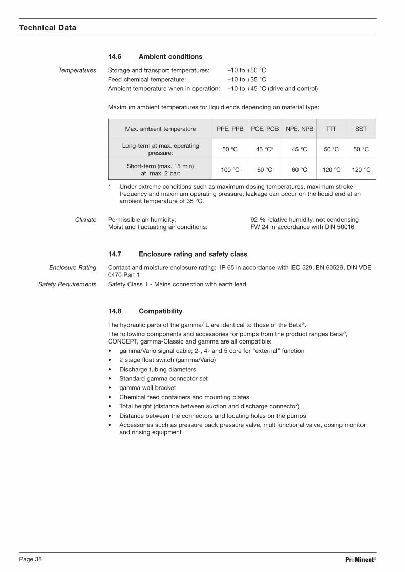
ProMinent®Page 38
Technical Data
14.6 Ambient conditions
Temperatures Storage and transport temperatures: –10 to +50 °C
Feed chemical temperature: –10 to +35 °C
Ambient temperature when in operation: –10 to +45 °C (drive and control)
Maximum ambient temperatures for liquid ends depending on material type:
erutarepmettneibma.xaM BPP,EPP BCP,ECP BPN,EPN TTT TSS
gnitarepo.xamtamret-gnoL:erusserp
C°05 *C°54 C°54 C°05 C°05
)nim51.xam(mret-trohS:rab2.xamta
C°001 C°06 C°06 C°021 C°021
* Under extreme conditions such as maximum dosing temperatures, maximum strokefrequency and maximum operating pressure, leakage can occur on the liquid end at anambient temperature of 35 °C.
Climate Permissible air humidity: 92 % relative humidity, not condensingMoist and fluctuating air conditions: FW 24 in accordance with DIN 50016
14.7 Enclosure rating and safety class
Enclosure Rating Contact and moisture enclosure rating: IP 65 in accordance with IEC 529, EN 60529, DIN VDE0470 Part 1
Safety Requirements Safety Class 1 - Mains connection with earth lead
14.8 Compatibility
The hydraulic parts of the gamma/ L are identical to those of the Beta®.
The following components and accessories for pumps from the product ranges Beta®,CONCEPT, gamma-Classic and gamma are all compatible:
• gamma/Vario signal cable; 2-, 4- and 5 core for “external” function
• 2 stage float switch (gamma/Vario)
• Discharge tubing diameters
• Standard gamma connector set
• gamma wall bracket
• Chemical feed containers and mounting plates
• Total height (distance between suction and discharge connector)
• Distance between the connectors and locating holes on the pumps
• Accessories such as pressure back pressure valve, multifunctional valve, dosing monitorand rinsing equipment

ProMinent® Page 39
Accessories
15 Accessories
CAUTION
The fitting and installing of ProMinent® dosing pumps using parts from othersuppliers which have not been tested and recommended by ProMinent isinadmissible and can result in harm to personnel and equipment, for which noliability will be accepted.
Level switch
2-stage with 2m connection cable
Fault indicating relay
To signal faults
Fault indicating and pacing relay
For timing other equipment and for indicating faults.
Signal cable
Universal signal cable: 5 core / 2.5 and 10 m
External contact cable: 2 core / 2.5 and 10 m
Foot valves
With suction filter and non-return valve for connection at the end of the suction tubing.
Discharge valve
With spring-loaded non-return valve for dosing into open or closed systems and for connectingdischarge tubing.
Discharge lances
For dosing into large pipes and to prevent blockage when dosing crystallising substances.
Back pressure valves
For precision dosing when operating pressure is low or as a relief valve.
Accumulator without diaphragm
For reducing pulsation, e.g. with long dosing lines.
Dosing monitors
For monitoring dosing. After pre-set number of failed strokes the error message displays andthe dosing pump switches off.
Suction lances
With foot valve and float switch for disposable drums or chemical feed containers
Chemical feed container
To contain 35 to 1000 litres with lockable screw top and necessary accessories.
Manual/electronic stirrers
For mixing and batching of feed solutions.
Bracket
For stable pump mounting.

ProMinent®Page 40
gamma/ L Dimensions
PPE, PPB material versions
15
12 (not for 0232)
80
102
E
101
160
F147
9636
KL
M
ProM
inent
®
Fig. 31
Measurements in mm
L/ammag L/ammag L/ammag L/ammag L/ammag 07M 07M 07M 07M 07M L/ammag L/ammag L/ammag L/ammag L/ammag 58M 58M 58M 58M 58M
2061-0001 2061-0001 2061-0001 2061-0001 2061-0001 5001 5001 5001 5001 5001 3140-8070 3140-8070 3140-8070 3140-8070 3140-8070 0220 0220 0220 0220 0220 5061 5061 5061 5061 5061 3170-8001 3170-8001 3170-8001 3170-8001 3170-8001 0240 0240 0240 0240 0240 2320 2320 2320 2320 2320
EEEEE 32 31 51 51 31 51 51 5
FFFFF 681 391 191 191 391 191 191 791
KKKKK 17 17 47 67 17 47 67 67
LLLLL 601 501 801 011 501 801 011 19
MMMMM 07Ø 09Ø 09Ø 09Ø 09Ø 09Ø 09Ø 011Ø
PCE, PCB material versions
15
13,8
80
102
E
101
160
F
14796
36K
L
MProMinent®
Fig. 32
Measurements in mm
07ML/ammag 07ML/ammag 07ML/ammag 07ML/ammag 07ML/ammag 58ML/ammag 58ML/ammag 58ML/ammag 58ML/ammag 58ML/ammag
1061-0001 1061-0001 1061-0001 1061-0001 1061-0001 2061 2061 2061 2061 2061 5001 5001 5001 5001 5001 8070 8070 8070 8070 8070 0220-3140 0220-3140 0220-3140 0220-3140 0220-3140 5061 5061 5061 5061 5061 8001 8001 8001 8001 8001 0240-3170 0240-3170 0240-3170 0240-3170 0240-3170 2320 2320 2320 2320 2320
EEEEE 52 32 61 31 51 61 31 51 5
FFFFF 771 971 881 981 981 881 981 981 991
KKKKK 77 77 47 47 67 47 47 67 67
LLLLL 501 501 201 201 401 201 201 401 501
MMMMM )07Ø(26 )07Ø(66 09Ø 09Ø 09Ø 09Ø 09Ø 09Ø 011Ø

ProMinent® Page 41
gamma/ L Dimensions
NPE, NPB material versions (non-bleed)
15
80
102E
101
160
F
14796
36K
L
MProMinent®
Fig. 33
Measurements in mm
L/ammag L/ammag L/ammag L/ammag L/ammag 07M 07M 07M 07M 07M 58ML/ammag 58ML/ammag 58ML/ammag 58ML/ammag 58ML/ammag
1061-0001 1061-0001 1061-0001 1061-0001 1061-0001 2061 2061 2061 2061 2061 5001 5001 5001 5001 5001 8070 8070 8070 8070 8070 0220-3140 0220-3140 0220-3140 0220-3140 0220-3140 5061 5061 5061 5061 5061 3170-8001 3170-8001 3170-8001 3170-8001 3170-8001 0240 0240 0240 0240 0240 2320 2320 2320 2320 2320
EEEEE 52 32 61 51 51 61 51 51 5
FFFFF 771 971 881 981 981 881 981 981 991
KKKKK 77 77 47 47 67 47 47 67 67
LLLLL 29 29 98 98 19 98 98 19 19
MMMMM )07Ø(26 )07Ø(66 09Ø 09Ø 09Ø 09Ø 09Ø 09Ø 011Ø
NPE, NPB material versions (with bleed function)
15
13,8
80
102
E
101
160
F
14796
36K
L
MProMinent®
Fig. 34
Measurements in mm
L/ammag L/ammag L/ammag L/ammag L/ammag 07M 07M 07M 07M 07M 58ML/ammag 58ML/ammag 58ML/ammag 58ML/ammag 58ML/ammag
1061-0001 1061-0001 1061-0001 1061-0001 1061-0001 2061 2061 2061 2061 2061 5001 5001 5001 5001 5001 8070 8070 8070 8070 8070 0220-3140 0220-3140 0220-3140 0220-3140 0220-3140 5061 5061 5061 5061 5061 8001 8001 8001 8001 8001 0240-3170 0240-3170 0240-3170 0240-3170 0240-3170 2320 2320 2320 2320 2320
EEEEE 52 32 61 31 51 61 31 51 5
FFFFF 771 971 881 981 981 881 981 981 991
KKKKK 77 77 47 47 67 47 47 67 67
LLLLL 501 501 201 201 401 201 201 401 501
MMMMM )07Ø(26 )07Ø(66 09Ø 09Ø 09Ø 09Ø 09Ø 09Ø 011Ø

ProMinent®Page 42
gamma/ L Dimensions
PPE, PPB, NPE, NPB, SEK material versions
15
44
80
102
E
101
160
F147
9636
KL
M
3
26,5
Schlaucheinlegen
durch-ziehen
Fig. 35
Measurements in mm
L/ammag L/ammag L/ammag L/ammag L/ammag 07M 07M 07M 07M 07M 58ML/ammag 58ML/ammag 58ML/ammag 58ML/ammag 58ML/ammag
1061 1061 1061 1061 1061 2061 2061 2061 2061 2061 5001 5001 5001 5001 5001 8070 8070 8070 8070 8070 0220-3140 0220-3140 0220-3140 0220-3140 0220-3140 5061 5061 5061 5061 5061 3170-8001 3170-8001 3170-8001 3170-8001 3170-8001 0240 0240 0240 0240 0240
EEEEE 52 32 61 51 51 61 51 51
FFFFF 771 971 881 981 981 881 981 981
KKKKK 77 77 47 47 67 47 47 67
LLLLL 29 29 98 98 19 98 98 19
MMMMM )06Ø(26 )07Ø(66 09Ø 09Ø 09Ø 09Ø 09Ø 09Ø
TTT material versions
1580
102
E
101
160
F
14796
36K
L
MProMinent®
Fig. 36
Measurements in mm
L/ammag L/ammag L/ammag L/ammag L/ammag 07M 07M 07M 07M 07M 58ML/ammag 58ML/ammag 58ML/ammag 58ML/ammag 58ML/ammag
1061-0001 1061-0001 1061-0001 1061-0001 1061-0001 2061 2061 2061 2061 2061 5001 5001 5001 5001 5001 0220-8070 0220-8070 0220-8070 0220-8070 0220-8070 5061 5061 5061 5061 5061 0240-8001 0240-8001 0240-8001 0240-8001 0240-8001 2320 2320 2320 2320 2320
EEEEE 23 52 32 7- 32 7- 51-
FFFFF 071 871 971 902 971 902 712
KKKKK 87 27 57 77 57 57 87
LLLLL 19 78 09 59 09 59 79
MMMMM )06Ø(15 )07Ø(66 )08Ø(86 )58Ø(18 )08Ø(86 )58Ø(18 )001Ø(69

ProMinent® Page 43
gamma/ L Dimensions
SST material versions
15
80102
E
101
160
F
147
9636
KL
MProMinent®
Fig. 37
Measurements in mm
L/ammag L/ammag L/ammag L/ammag L/ammag 07M 07M 07M 07M 07M L/ammag L/ammag L/ammag L/ammag L/ammag 58M 58M 58M 58M 58M
1061-0001 1061-0001 1061-0001 1061-0001 1061-0001 2061 2061 2061 2061 2061 5001 5001 5001 5001 5001 3140-8070 3140-8070 3140-8070 3140-8070 3140-8070 0220 0220 0220 0220 0220 5061 5061 5061 5061 5061 3170-8001 3170-8001 3170-8001 3170-8001 3170-8001 0240 0240 0240 0240 0240 2320 2320 2320 2320 2320
EEEEE 04 33 13 2- 3- 13 2- 3- 01-
FFFFF 261 071 171 302 402 171 302 402 212
KKKKK 87 27 57 77 77 57 77 77 87
LLLLL 98 58 88 39 39 88 39 39 59
MMMMM )06Ø(15 )07Ø(66 )08Ø(86 )58Ø(18 )58Ø(18 )08Ø(18 )58Ø(18 )58Ø(18 )001Ø(69

ProMinent®Page 44
Exploded diagrams of liquid ends
Liquid end 1000 - 1005 (1605)PP with coarse/fine bleed
ProMine
nt
The listed items are included in the spare parts kit.
Subject to technical alterations.
Spare parts kits for:
Type Material Order No.
1000 PPE 10016441601 PPE 10016451602 PPE 10016461005 (1605) PPE 1001647
1000 PPB 10016521601 PPB 10016531602 PPB 10016541005 (1605) PPB 1001655
4 valve balls 404201
Connector kit
Diaphragm 1000 1000244Diaphragm 1601 1000245Diaphragm 1602 1000246Diaphragm 1005 1000247
1 seal set EPDM 10017751 seal set FPM 1001773
Suction valve set PPE 792644Suction valve set PPB 792646
Discharge valve set PPE 740350Discharge valve set PPB 740351
Connector kit 6/4 PPE 817150Connector kit 8/5 PPE 817153Connector kit 6/4 PPB 817166Connector kit 8/5 PPB 817167

ProMinent® Page 45
Exploded diagrams of liquid ends
Liquid end 0708 (1008) - 0220 (0420)PP with coarse/fine bleed
ProMinent
The listed items are included in the spare parts kit.
Subject to technical alterations.
Spare parts kits for:
Type Material Order No.
0708 (1008) PPE 10016480413 (0713) PPE 10016490220 (0420) PPE 1001650
0708 (1008) PPB 10016560413 (0713) PPB 10016570220 (0420) PPB 1001658
4 valve balls 404281
Connector kit
Diaphragm 0708 1000248Diaphragm 0413 1000249Diaphragm 0220 1000250
1 seal set EPDM 10017761 seal set FPM 1001774
Suction valve set PPE 1001437Suction valve set PPB 1001436
Discharge valve set PPE 1001441Discharge valve set PPB 1001440
Connector kit 8/5 PPE 817153Connector kit 12/9 PPE 817151Connector kit 8/5 PPB 817167Connector kit 12/9 PPB 817168

ProMinent®Page 46
Exploded diagrams of liquid ends
Liquid end 0232PP without coarse/fine bleed
The listed items are included in the spare parts kit.
Subject to technical alterations.
Spare parts kits for:
Type Material Order No.
0232 PPE 1001651
0232 PPB 1001659
1 seal set EPDM 10017761 seal set FPM 1001774
4 valve balls 404281
Connector kit
Suction valve set PPE 1001437Suction valve set PPB 1001436
Diaphragm 0232 1000251
Discharge valve set PPE 1001441Discharge valve set PPB 1001440
Connector kit 12/9 PPE 817151Connector kit 12/9 PPB 817168

ProMinent® Page 47
Exploded diagrams of liquid ends
Liquid end 1000 - 1005 (1605)PC / NP with coarse/fine bleed
The listed items are included in the spare parts kit.
Subject to technical alterations.
Spare parts kits for:
Type Material Order No.
1000 PCE / NPE 10017131601 PCE / NPE 10017141602 PCE / NPE 10017151005 (1605) PCE / NPE 1001716
1000 PCB / NPB 10017211601 PCB / NPB 10017221602 PCB / NPB 10017231005 (1605) PCB / NPB 1001724
4 valve balls 404201
Connector kit
Diaphragm 1000 1000244Diaphragm 1601 1000245Diaphragm 1602 1000246Diaphragm 1005 1000247
1 seal set EPDM 10017751 seal set FPM 1001773
Suction valve set PCE 792119Suction valve set PCB 792026
Discharge valve set PCE 740349Discharge valve set PCB 740348
Connector kit 6/4 PCE 817060Connector kit 8/5 PCE 817048Connector kit 6/4 PCB 817050Connector kit 8/5 PCB 817053

ProMinent®Page 48
Exploded diagrams of liquid ends
Liquid end 0708 (1008) - 0220 (0420)PC / NP with coarse/fine bleed
The listed items are included in the spare parts kit.
Subject to technical alterations.
Spare parts kits for:
Type Material Order No.
0708 (1008) PCE / NPE 10017160413 (0713) PCE / NPE 10017170220 (0420) PCE / NPE 1001718
0708 (1008) PCB / NPB 10017250413 (0713) PCB / NPB 10017260220 (0420) PCB / NPB 1001727
4 valve balls 404281
Connector kit
Diaphragm 0708 1000248Diaphragm 0413 1000249Diaphragm 0220 1000250
1 seal set EPDM 10017761 seal set FPM 1001774
Suction valve set PCE 1001435Suction valve set PCB 1001434
Discharge valve set PCE 1001439Discharge valve set PCB 1001438
Connector kit 8/5 PCE 817048Connector kit 12/9 PCE 817049Connector kit 8/5 PCB 817053Connector kit 12/9 PCB 817051

ProMinent® Page 49
Exploded diagrams of liquid ends
Liquid end 0232PC without coarse/fine bleed
The listed items are included in the spare parts kit.
Subject to technical alterations.
Spare parts kits for:
Type Material Order No.
0232 PCE / NPE 1001719
0232 PCB / NPB 1001728
1 seal set EPDM 10017761 seal set FPM 1001774
4 valve balls 404281
Connector kit
Suction valve set PCE 1001435Suction valve set PCB 1001434
Diaphragm 0232 1000251
Discharge valve set PCE 1001439Discharge valve set PCB 1001438
Connector kit 12/9 PCE 817049Connector kit 12/9 PCB 817051

ProMinent®Page 50
Exploded diagrams of liquid ends
Liquid end 0232NP with coarse/fine bleed
The listed items are included in the spare parts kit.
Subject to technical alterations.
Spare parts kits for:
Type Material Order No.
0232 PCE / NPE 1001719
0232 PCB / NPB 1001728
1 seal set EPDM 10017761 seal set FPM 1001774
4 valve balls 404281
Connector kit
Suction valve set PCE 1001435Suction valve set PCB 1001434
Diaphragm 0232 1000251
Discharge valve set PCE 1001439Discharge valve set PCB 1001438
Connector kit 12/9 PCE 817049Connector kit 12/9 PCB 817051

ProMinent® Page 51
Exploded diagrams of liquid ends
Liquid end 1000 - 1005 (1605)NP without coarse/fine bleed
The listed items are included in the spare parts kit.
Subject to technical alterations.
Spare parts kits for:
Type Material Order No.
1000 PCE / NPE 10017131601 PCE / NPE 10017141602 PCE / NPE 10017151005 (1605) PCE / NPE 1001716
1000 PCB / NPB 10017211601 PCB / NPB 10017221602 PCB / NPB 10017231005 (1605) PCB / NPB 1001724
4 valve balls 404201
Connector kit
Diaphragm 1000 1000244Diaphragm 1601 1000245Diaphragm 1602 1000246Diaphragm 1005 1000247
1 seal set EPDM 10017751 seal set FPM 1001773
Suction valve set PCE 792119Suction valve set PCB 792026
Discharge valve set PCE 740349Discharge valve set PCB 740348
Connector kit 6/4 PCE 817060Connector kit 8/5 PCE 817048Connector kit 6/4 PCB 817050Connector kit 8/5 PCB 817053

ProMinent®Page 52
Exploded diagrams of liquid ends
Liquid end 0708 (1008) - 0220 (0420)NP without coarse/fine bleed
The listed items are included in the spare parts kit.
Subject to technical alterations.
Spare parts kits for:
Type Material Order No.
0708 (1008) PCE / NPE 10017160413 (0713) PCE / NPE 10017170220 (0420) PCE / NPE 1001718
0708 (1008) PCB / NPB 10017250413 (0713) PCB / NPB 10017260220 (0420) PCB / NPB 1001727
4 valve balls 404281
Connector kit
Diaphragm 0708 1000248Diaphragm 0413 1000249Diaphragm 0220 1000250
1 seal set EPDM 10017761 seal set FPM 1001774
Suction valve set PCE 1001435Suction valve set PCB 1001434
Discharge valve set PCE 1001439Discharge valve set PCB 1001438
Connector kit 8/5 PCE 817048Connector kit 12/9 PCE 817049Connector kit 8/5 PCB 817053Connector kit 12/9 PCB 817051

ProMinent® Page 53
Exploded diagrams of liquid ends
Liquid end 0232NP without coarse/fine bleed
The listed items are included in the spare parts kit.
Subject to technical alterations.
Spare parts kits for:
Type Material Order No.
0232 PCE / NPE 1001719
0232 PCB / NPB 1001728
1 seal set EPDM 10017761 seal set FPM 1001774
4 valve balls 404281
Connector kit
Suction valve set PCE 1001435Suction valve set PCB 1001434
Diaphragm 0232 1000251
Discharge valve set PCE 1001439Discharge valve set PCB 1001438
Connector kit 12/9 PCE 817049Connector kit 12/9 PCB 817051

ProMinent®Page 54
Exploded diagrams of liquid ends
Liquid end 1601 - 1005 (1605)PP / NP self-degassing
The listed items are included in the spare parts kit.
Subject to technical alterations.
Spare parts kits for:
Type Material Order No.
1601 PPE 10017561602 PPE 10017571005 (1605) PPE 1001758
1601 PPB 10017621602 PPB 10017631005 (1605) PPB 1001764
1601 NPE 10016601602 NPE 10016611005 (1605) NPE 1001662
1601 NPB 10016661602 NPB 10016671005 (1605) NPB 1001668
4 valve balls 404201
Diaphragm 1601 1000245Diaphragm 1602 1000246Diaphragm 1005 1000247
1 seal set EPDM 10016741 seal set FPM 1001672
Suction valve set PPE 792644Suction valve set PPB 792646Suction valve set PCE 792119Suction valve set PCB 792026
Discharge valve set PPE 1001067Discharge valve set PPB 1001066Discharge valve set PCE 1001065Discharge valve set PCB 1001064
Connector kit 6/4 PPE 817160Connector kit 6/4 PPB 817173Connector kit 6/4 PCE 791161Connector kit 6/4 PCB 817065
Connector kit 6/4 PPE 817160Connector kit 8/5 PPE 817161Connector kit 6/4 PPB 817173Connector kit 8/5 PPB 817174Connector kit 6/4 PCE 791161Connector kit 8/5 PCE 792058Connector kit 6/4 PCB 817065Connector kit 8/5 PCB 817066
Connector kit 6/4 PPE 817160Connector kit 8/5 PPE 817161Connector kit 6/4 PPB 817173Connector kit 8/5 PPB 817174Connector kit 6/4 PCE 791161Connector kit 8/5 PCE 792058Connector kit 6/4 PCB 817065Connector kit 8/5 PCB 817066
Vent valve PPE 1001063Vent valve PPB 1001062Vent valve PCE 1001061Vent valve PCB 1001060

ProMinent® Page 55
Exploded diagrams of liquid ends
Liquid end 0708 (1008) - 0220 (0420)PP / NP self-degassing
The listed items are included in the spare parts kit.
Subject to technical alterations.
Spare parts kits for:
Type Material Order No.
0708 (1008) PPE 10017590413 (0713) PPE 10017600220 (0420) PPE 1001761
0708 (1008) PPB 10017650413 (0713) PPB 10017660220 (0420) PPB 1001767
0708 (1008) NPE 10016630413 (0713) NPE 10016640220 (0420) NPE 1001665
0708 (1008) NPB 10016690413 (0713) NPB 10016700220 (0420) NPB 1001671
1 valve ball 404201
3 valve balls 404281
Diaphragm 0708 1000248Diaphragm 0413 1000249Diaphragm 0220 1000250
1 seal set EPDM 10016751 seal set FPM 1001673
Suction valve set PPE 1001437Suction valve set PPB 1001436Suction valve set PCE 1001435Suction valve set PCB 1001434
Discharge valve set PPE 1001071Discharge valve set PPB 1001070Discharge valve set PCE 1001069Discharge valve set PCB 1001068
Connector kit 6/4 PPE 817160Connector kit 6/4 PPB 817173Connector kit 6/4 PCE 791161Connector kit 6/4 PCB 817065
Connector kit 8/5 PPE 817161Connector kit 12/9 PPE 817162Connector kit 8/5 PPB 817174Connector kit 12/9 PPB 817175Connector kit 8/5 PCE 792058Connector kit 12/9 PCE 790577Connector kit 8/5 PCB 817066Connector kit 12/9 PCB 817067
Connector kit 8/5 PPE 817161Connector kit 12/9 PPE 817162Connector kit 8/5 PPB 817174Connector kit 12/9 PPB 817175Connector kit 8/5 PCE 792058Connector kit 12/9 PCE 790577Connector kit 8/5 PCB 817066Connector kit 12/9 PCB 817067
Vent valve PPE 1001063Vent valve PPB 1001062Vent valve PCE 1001061Vent valve PCB 1001060

ProMinent®Page 56
Exploded diagrams of liquid ends
Liquid end 1000 - 1005 (1605)TT
The listed items are included in the spare parts kit.
Subject to technical alterations.
Spare parts kits for:
Type Material Order No.
1000 TTT 10017371601 TTT 10017381602 TTT 10017391005 (1605) TTT 1001740
11 seals PTFE 483907
4 valve balls 404201
Connector kit
Diaphragm 1000 1000244Diaphragm 1601 1000245Diaphragm 1602 1000246Diaphragm 1005 1000247
Discharge valve set TTT 809406
Suction valve set TTT 809407
Connector kit 6/4 TTT 817201Connector kit 8/5 TTT 817204

ProMinent® Page 57
The listed items are included in the spare parts kit.
Subject to technical alterations.
Spare parts kits for:
Type Material Order No.
0708 (1008) TTT 10017410413 (0713) TTT 10017420220 (0420) TTT 1001754
12 seals PTFE 483975
4 valve balls 404281
Connector kit
Diaphragm 0708 1000248Diaphragm 0413 1000249Diaphragm 0220 1000250
Discharge valve set TTT 809444
Suction valve set TTT 809445
Connector kit 8/5 TTT 817204Connector kit 12/9 TTT 817202
Liquid end 0708 (1008) - 0220 (0420)TT
Exploded diagrams of liquid ends

ProMinent®Page 58
The listed items are included in the spare parts kit.
Subject to technical alterations.
Spare parts kits for:
Type Material Order No.
0232 TTT 1001755
12 seals PTFE 483975
4 valve balls 404281
Connector kit
Diaphragm 0232 1000251
Discharge valve set TTT 809444
Suction valve set TTT 809445
Connector kit 12/9 TTT 817202
Liquid end 0232TT
Exploded diagrams of liquid ends

ProMinent® Page 59
Exploded diagrams of liquid ends
Liquid end 1000 - 1005 (1605)SS
The listed items are included in the spare parts kit.
Subject to technical alterations.
Spare parts kits for:
Type Material Order No.
1000 SST 10017291601 SST 10017301602 SST 10017311005 (1605) SST 1001732
12 seals PTFE 483907
4 valve balls 404201
Connector kit
Diaphragm 1000 1000244Diaphragm 1601 1000245Diaphragm 1602 1000246Diaphragm 1005 1000247
Suction valve set 6 mm SST 809419
Discharge valve set 6 mm SST 809418
Connector kit 6 mm SS 104233

ProMinent®Page 60
Exploded diagrams of liquid ends
Liquid end 0708 (1008) - 0220 (0420)SS
The listed items are included in the spare parts kit.
Subject to technical alterations.
Spare parts kits for:
Type Material Order No.
0708 (1008) SST 10017330413 (0713) SST 10017340220 (0420) SST 1001735
12 seals PTFE 483975
4 valve balls 404281
Connector kit
Diaphragm 0708 1000248Diaphragm 0413 1000249Diaphragm 0220 1000250
Suction valve set 8 mm SST 809495Suction valve set 12 mm SST 809447
Discharge valve set 8 mm SST 809494Discharge valve set 12 mm SST 809446
Connector kit 8 mm SS 104237Connector kit 12 mm SS 104245

ProMinent® Page 61
Exploded diagrams of liquid ends
Liquid end 0232SS
The listed items are included in the spare parts kit.
Subject to technical alterations.
Spare parts kits for:
Type Material Order No.
0232 SST 1001736
12 seals PTFE 483975
4 valve balls 404281
Connector kit
Diaphragm 0232 1000251
Discharge valve set 12 mm SST 809446
Suction valve set 12 mm SST 809447
Connector kit 12 mm SS 104245

ProMinent®Page 62
0
0,51
1,5
12
46
81
1316
0
0,1
0,2
0,3
0,4
0,5
0,6
0,7
0,8
0,9
0%10
%20
%30
%40
%50
%60
%70
%80
%90
%10
0%
90 80 70100 50 40 30 20 1060
0
0,51
1,5
12
46
811
1316
0
0,2
0,4
0,6
0,81
1,2
1,4
1,6
0%10
%20
%30
%40
%50
%60
%70
%80
%90
%10
0%
90 80 70100 50 40 30 20 1060
GA
La 1
000
at m
ediu
m o
pera
ting
pres
sure
Str
oke
leng
th
Ope
ratin
g pr
essu
re
Cor
rect
ion
fact
or
Fee
d ra
te[l/
h]S
trok
e ra
te[%
]G
ALa
160
1 at
med
ium
ope
ratin
g pr
essu
re
Str
oke
leng
th
Ope
ratin
g pr
essu
re
Cor
rect
ion
fact
or
Fee
d ra
te[l/
h]S
trok
e ra
te[%
]
Feed rate settings diagrams
18 s
trok
es/m
in
36 s
trok
es/m
in
54 s
trok
es/m
in
72 s
trok
es/m
in
180
stro
kes/
min
162
stro
kes/
min
144
stro
kes/
min
126
stro
kes/
min
108
stro
kes/
min
90 s
trok
es/m
in
18 s
trok
es/m
in
36 s
trok
es/m
in
54 s
trok
es/m
in
72 s
trok
es/m
in
180
stro
kes/
min
162
stro
kes/
min
144
stro
kes/
min
126
stro
kes/
min
108
stro
kes/
min
90 s
trok
es/m
in

ProMinent® Page 63
0
0,51
1,5
12
46
811
1316
0
0,51
1,52
2,53 0%
10%
20%
30%
40%
50%
60%
70%
80%
90%
100%
90 80 70100 50 40 30 20 1060
0
0,2
0,4
0,6
0,81
1,2
12
45
810
0123456 0%10
%20
%30
%40
%50
%60
%70
%80
%90
%10
0%
90 80 70100 50 40 30 20 1060
Feed rate settings diagrams
GA
La 1
602
at m
ediu
m o
pera
ting
pres
sure
Str
oke
leng
th
Ope
ratin
g pr
essu
re
Cor
rect
ion
fact
or
Fee
d ra
te[l/
h]S
trok
e ra
te[%
]G
ALa
100
5 at
med
ium
ope
ratin
g pr
essu
re
Str
oke
leng
th
Ope
ratin
g pr
essu
re
Cor
rect
ion
fact
or
Fee
d ra
te[l/
h]S
trok
e ra
te[%
]
18 s
trok
es/m
in
36 s
trok
es/m
in
54 s
trok
es/m
in
72 s
trok
es/m
in
180
stro
kes/
min
162
stro
kes/
min
144
stro
kes/
min
126
stro
kes/
min
108
stro
kes/
min
90 s
trok
es/m
in
18 s
trok
es/m
in
36 s
trok
es/m
in
54 s
trok
es/m
in
72 s
trok
es/m
in
180
stro
kes/
min
162
stro
kes/
min
144
stro
kes/
min
126
stro
kes/
min
108
stro
kes/
min
90 s
trok
es/m
in
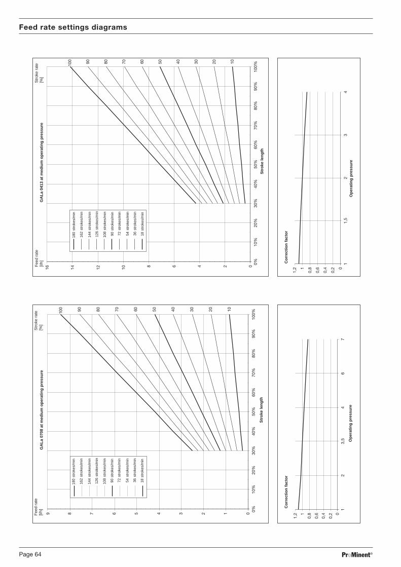
ProMinent®Page 64
0
0,2
0,4
0,6
0,81
1,2
12
3,5
46
7
0123456789 0%10
%20
%30
%40
%50
%60
%70
%80
%90
%10
0%
90 80 70100 50 40 30 20 1060
0
0,2
0,4
0,6
0,81
1,2
11,
52
34
0246810121416
0%10
%20
%30
%40
%50
%60
%70
%80
%90
%10
0%
90 80 70100 50 40 30 20 1060
Feed rate settings diagrams
GA
La 0
708
at m
ediu
m o
pera
ting
pres
sure
Str
oke
leng
th
Ope
ratin
g pr
essu
re
Cor
rect
ion
fact
or
Fee
d ra
te[l/
h]S
trok
e ra
te[%
]G
ALa
041
3 at
med
ium
ope
ratin
g pr
essu
re
Str
oke
leng
th
Ope
ratin
g pr
essu
re
Cor
rect
ion
fact
or
Fee
d ra
te[l/
h]S
trok
e ra
te[%
]
18 s
trok
es/m
in
36 s
trok
es/m
in
54 s
trok
es/m
in
72 s
trok
es/m
in
180
stro
kes/
min
162
stro
kes/
min
144
stro
kes/
min
126
stro
kes/
min
108
stro
kes/
min
90 s
trok
es/m
in
18 s
trok
es/m
in
36 s
trok
es/m
in
54 s
trok
es/m
in
72 s
trok
es/m
in
180
stro
kes/
min
162
stro
kes/
min
144
stro
kes/
min
126
stro
kes/
min
108
stro
kes/
min
90 s
trok
es/m
in

ProMinent® Page 65
0,8
0,850,
9
0,95
1
1,05
0,5
11,
52
0510152025
0%10
%20
%30
%40
%50
%60
%70
%80
%90
%10
0%
90 80 70100 50 40 30 20 1060
0
0,51
1,52
12
46
811
1316
0123456 0%10
%20
%30
%40
%50
%60
%70
%80
%90
%10
0%
90 80 70100 50 40 30 20 1060
GA
La 0
220
at m
ediu
m o
pera
ting
pres
sure
Str
oke
leng
th
Ope
ratin
g pr
essu
re
Cor
rect
ion
fact
or
Fee
d ra
te[l/
h]S
trok
e ra
te[%
]G
ALa
160
5 at
med
ium
ope
ratin
g pr
essu
re
Str
oke
leng
th
Ope
ratin
g pr
essu
re
Cor
rect
ion
fact
or
Fee
d ra
te[l/
h]S
trok
e ra
te[%
]
Feed rate settings diagrams
18 s
trok
es/m
in
36 s
trok
es/m
in
54 s
trok
es/m
in
72 s
trok
es/m
in
180
stro
kes/
min
162
stro
kes/
min
144
stro
kes/
min
126
stro
kes/
min
108
stro
kes/
min
90 s
trok
es/m
in
18 s
trok
es/m
in
36 s
trok
es/m
in
54 s
trok
es/m
in
72 s
trok
es/m
in
180
stro
kes/
min
162
stro
kes/
min
144
stro
kes/
min
126
stro
kes/
min
108
stro
kes/
min
90 s
trok
es/m
in

ProMinent®Page 66
00,
20,
40,
60,
811,
21,
4
12
3,5
56
10
0123456789 0%10
%20
%30
%40
%50
%60
%70
%80
%90
%10
0%
90 80 70100 50 40 30 20 1060
0
0,2
0,4
0,6
0,81
1,2
12
3,5
46
7
02468101214
0%10
%20
%30
%40
%50
%60
%70
%80
%90
%10
0%
90 80 70100 50 40 30 20 1060
Feed rate settings diagrams
GA
La 1
008
at m
ediu
m o
pera
ting
pres
sure
Str
oke
leng
th
Ope
ratin
g pr
essu
re
Cor
rect
ion
fact
or
Fee
d ra
te[l/
h]S
trok
e ra
te[%
]G
ALa
071
3 at
med
ium
ope
ratin
g pr
essu
re
Str
oke
leng
th
Ope
ratin
g pr
essu
re
Cor
rect
ion
fact
or
Fee
d ra
te[l/
h]S
trok
e ra
te[%
]
18 s
trok
es/m
in
36 s
trok
es/m
in
54 s
trok
es/m
in
72 s
trok
es/m
in
180
stro
kes/
min
162
stro
kes/
min
144
stro
kes/
min
126
stro
kes/
min
108
stro
kes/
min
90 s
trok
es/m
in
18 s
trok
es/m
in
36 s
trok
es/m
in
54 s
trok
es/m
in
72 s
trok
es/m
in
180
stro
kes/
min
162
stro
kes/
min
144
stro
kes/
min
126
stro
kes/
min
108
stro
kes/
min
90 s
trok
es/m
in

ProMinent® Page 67
0
0,2
0,4
0,6
0,81
1,2
11,
52
34
0510152025
0%10
%20
%30
%40
%50
%60
%70
%80
%90
%10
0%
90 80 70100 50 40 30 20 1060
0
0,2
0,4
0,6
0,81
1,2
0,5
11,
52
0510152025303540
0%10
%20
%30
%40
%50
%60
%70
%80
%90
%10
0%
90 80 70100 50 40 30 20 1060
GA
La 0
420
at m
ediu
m o
pera
ting
pres
sure
Str
oke
leng
th
Ope
ratin
g pr
essu
re
Cor
rect
ion
fact
or
Fee
d ra
te[l/
h]S
trok
e ra
te[%
]G
ALa
023
2 at
med
ium
ope
ratin
g pr
essu
re
Str
oke
leng
th
Ope
ratin
g pr
essu
re
Cor
rect
ion
fact
or
Fee
d ra
te[l/
h]S
trok
e ra
te[%
]
Feed rate settings diagrams
18 s
trok
es/m
in
36 s
trok
es/m
in
54 s
trok
es/m
in
72 s
trok
es/m
in
180
stro
kes/
min
162
stro
kes/
min
144
stro
kes/
min
126
stro
kes/
min
108
stro
kes/
min
90 s
trok
es/m
in
18 s
trok
es/m
in
36 s
trok
es/m
in
54 s
trok
es/m
in
72 s
trok
es/m
in
180
stro
kes/
min
162
stro
kes/
min
144
stro
kes/
min
126
stro
kes/
min
108
stro
kes/
min
90 s
trok
es/m
in

ProMinent®Page 68
EC-Declaration of Conformity

ProMinent® Page 69
Customer Specification Form
Client:
Project number: Date: q Sketch supplied:
Metering pump Type – ......................................................
Pump capacity l/h ......................................................
Stroking rate strokes/min ......................................................
Stroke length % ......................................................
Valve spring pressure, suction side bar ......................................................
Valve spring pressure, discharge side bar ......................................................
Chemicals Description/concentration –/% ............................ / .......................
Proportion suspended solids/particle size %/mm ............................ / .......................
Solid material/hardness –/(Mohs scale) ......................................................
Dynamic viscosity mPa s (cP) ......................................................
Density kg/m³ ......................................................
Vapour pressure at operating temperature bar/°C ......................................................
System: Suction side Pressure in suction container bar ......................................................
Nominal width, suction line DN/mm ............................ / .......................
Suction lift min./max. m ............................ / .......................
Suction pressure min./max. m ............................ / .......................
Length, suction line m ......................................................
Number of corner bends/valves – ......................................................
Pulsation dampener q with diaphragm .......................... ltr.
q without diaphragm ..................... ltr.
System: discharge side Static system pressure min./max. bar ............................ / .......................
Nominal width, suction line DN/mm ......................................................
Length, suction line m ......................................................
Feed lift m ......................................................
Number of corner bends/valves – ......................................................
Pulsation dampener q with diaphragm .......................... ltr.
q without diaphragm ..................... ltr.

ProMinent®Page 70
Company: .................................................................................. Tel. No.: ................................... Date: ........................................
Address: .........................................................................................................................................................................................
Authorised personnel: ....................................................................................................................................................................
Order number: ...................................................................Delivery date: ......................................................................................
gamma/ L type/identity code: ......................................... Serial number: ......................................................................................
Brief description of fault: .............................................................................................................................................................
........................................................................................................................................................................................................
........................................................................................................................................................................................................
Fault type
1 Mechanical fault 2 Electrical fault
q Unusual wear q Loose connectors, e.g. cables or plugs
q Worn part q Operating elements (e.g. switches)
q Break or other damage q Controller
q Corrosion
q Damaged in transit
3 Leakage 4 Poor/no chemical feed
q Connectors q Defective diaphragm
q Liquid end q Other
ProMinent® gamma/ L operating conditions:
Location/system description: .........................................................................................................................................................
Pump accessories used: ................................................................................................................................................................
........................................................................................................................................................................................................
........................................................................................................................................................................................................
........................................................................................................................................................................................................
Commissioned (Date): ....................................................................................................................................................................
Running time (approx. operating hours): ........................................................................................................................................
Please enclose customer specification form and sketch of system!
Guarantee Form
Please copy and send with the gamma/ L!In the event of failure of the dosing gamma/ L within the guarantee period we request that you return the gamma/ L
(cleaned) with a fully completed guarantee application.
▼
Please complete all sections!
Dosing Pump Guarantee Form No.

ProMinent® Page 71
Safety Declaration Form
Please copy and send with gamma/ L!
Safety Declaration
We hereby declare that the device enclosed
Type: .....................................................................................................................................
Serial number: .......................................................................................................................
is free from hazardous
• chemicals• biologicals• radioactive substances.
The device was thoroughly cleaned prior to sending.
Date/signed Company stamp