operating instructions magstop barriers type: mts 6/8 · operating instructions magstop barriers...
TRANSCRIPT

Operating Instructions
MAGSTOP Barriers
Type: MTS 6/8
Please read entire manual carefully before starting installation.
Technology
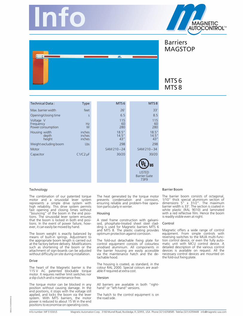
The combination of our patented torquemotor and a sinusoidal lever systemrepresents a simple drive system withhigh reliability. This drive system permitsfast opening and closing times without”bouncing” of the boom in the end posi-tions. The sinusoidal lever system ensuresthat the boom is locked in both end posi-tions. In the event of power failure, how-ever, it can easily be moved by hand.
The boom weight is exactly balanced bymeans of built-in springs. Adjustment tothe appropriate boom length is carried outat the factory before delivery. Modificationssuch as shortening of the boom or theattachment of sign-boards can be adjustedwithout difficulty on site during installation.
Drive
The heart of the Magnetic barrier is the115 V AC patented blockable torquemotor. It requires neither limit switches nora slip clutch and is maintenance-free.
The torque motor can be blocked in anyposition without causing damage. In theend positions, it stops with the voltage stillapplied, and locks the boom via the leversystem. With MTS barriers, the motorpower is reduced to about 15 W in the endpositions to economise on operating costs.
The heat generated by the torque motorprevents condensation and corrosion,ensuring reliable and problem-free opera-tion particularly in winter.
Housing
A steel frame construction with galvani-sed, phosphate-treated sheet steel clad-ding is used for Magnetic barriers MTS 6and MTS 8. The plastic coating providesoptimum protection against corrosion.
The fold-out detachable fixing plate forcontrol equipment consists of colourlessanodised aluminium. All components inthe barrier housing are easily accessiblevia the maintenance hatch and the de-tachable hood.
The housing is coated, as standard, in thecolour RAL 2000. Special colours are avail-able if required at extra cost.
Version
All barriers are available in both ”right-hand” or ”left-hand” versions.
The hatch to the control equipment is onthe road side.
Barrier Boom
The barrier boom consists of octagonal,1/10” thick special aluminium section ofdimensions 5” x 31/2”. The maximumbarrier width is 33’. The section is coated inwhite plastic (RAL 9010) and laminatedwith a red reflective film. Hence the boomis readily visible even at night.
Control
Magnetic offers a wide range of controlequipment. From simple controls withreversing switches to the MUA multi-func-tion control device, or even the fully auto-matic unit with MCU control device. Adetailed description of the various controldevices is available on request. All thenecessary control devices are mounted onthe fold-out fixing plate.
BarriersMAGSTOP
MTS 6MTS 8
Info number: MF 5103/US Magnetic Automation Corp. 3160 Murrell Road, Rockledge, FL 32955, USA Phone (321) 6358585 Telefax (321) 6359449 [email protected]
Technical Data : Type
Max. barrier width feet
Opening/closing time s
Voltage VFrequency HzPower consumption W
Housing width inchesdepth inchesheight inches
Weight excluding boom Lbs
Motor
Capacitor C1/C2 µF
MTS 6 MTS 8
26’ 33’
6.5 8.5
115 11560 60
280 280
18.5” 18.5”14.5” 14.5”
43” 43”
298 298
SAM 210 – 24 SAM 210 – 34
30/20 30/20
580U
S,51
03/0
/0/0
4.02
LISTEDBarrier Gate
73F9

Safety
The following safety points should beobserved with regard to the installationand operation of a Magnetic barrier:
1. The concrete foundation is to be pro-vided in accordance with Works Docu-ment Info MM 5115 by the builder.
2. A distance of at least 24” is to be main-tained between the boom tip and thenearest building or wall.
3. For permanent installation, a mainswitch which disconnects all poles is tobe provided by the builder.
4. Opening and closing operations mustbe observed! Installation of the operat-ing elements outside the field of view isnot permitted; a visual link must existbetween the barrier unit and the controlelements.
5. During operation, the presence of per-sons or goods in the movement zone ofthe boom is not permitted.
6. When a boom length of 12’ is exceed-ed, the installation of a pendulum sup-port or support post is required.
7. The boom fixing is designed to with-stand wind strengths of max. 10 BeaufortScale (= 10.44 Lb/sqft; 500 N/m2).
Electrical Connection
Electrical connection for standard versionMTS barriers is in accordance with the dia-gram overleaf.Where our control equipment is used, spe-cial wiring diagrams are to be observeddepending on the configuration. Thesecan be obtained from the factory.
Subject to technical modifications.
Dimensional Diagram for MTS
Connections for MTS – Deadman –
Magnetic Automation Corp. 3160 Murrell Road, Rockledge, FL 32955, USA Phone (321) 6358585 Telefax (321) 6359449 [email protected]

Info-number: MF 5115/ESubject to technical modifications.
BarriersMAGSTOP
Guidelines for foundations
580
E,M
F511
5/1/
04.0
4
Foundations for Barrier MIB andControl column MEC
In order to ensure the stability of the barrier,the foundation is to be constructed as-agreed with the TÜV (“Technical Monito-ring Association, Test Centre for ApplianceSafety”) and in accordance with the follo-wing guidelines.
1.Excavate a hole for the foundation tofrost-line depth (at least 800 mm). Thedimensions of the foundations at theboom must be at least 500 mm x 600 mmfor the MIB series barriers and MEC10N/H/L control column (Figure 1) and350 x 350 mm for the MEC 10M/E con-trol column (Figure 3).On the road side, the foundation is tobe 100 mm larger at the bottom thanthe top (Figure 1).
2.Lay separate conduits of 29 mm dia-meter for the power supply and controllines. An additional conduit with of29 mm diameter is to be inserted at road level for loops (Figure 1).
3.Concrete the foundation hole using BHPC 250 concrete (concrete strengthW = 25 N/mm2). For barriers, the con-crete must be reinforced (Figure 2).
4.A smooth finish must be provided in thehousing area, so that the barrier hou-sing sits flat level and stable.
5.Drill the bore holes for the anchor bolts in accordance with the layout planwhen the concrete has hardened suffi-ciently. For the MIB barriers, MEC con-trol column, bore hole Ø 10 mm, A =80 mm deep (Figure 1).
6.Set the appropriate anchor bolts intothe bore holes ( Figure 1) and assemblethe barrier housing in accordance withthe assembly instructions:
MIB 20/30/40 581E,5000MIB 10 580E,5123MEC 10N/H/L 580E,5201MEC 10M/E 580E,5203
7.Lay paving or other finishing materialas required.
500
190
155155 500190 155
155
600
1
2
34
5
A A80
0
road
190
3 x Ø12 740x410 St III5 x Ø8 440x440 St III
350
18085
85 35090
130
130
350
800
S0222
Foundation for Support post (Fig. 4)
The Magnetic support post is used with-boom lengths which exceed 3,5 m, to sup-port the boom in the horizontal position.
When preparing the foundation, it shouldbe ensured that the barrier and post foun-dations are at the same level. The bottomof the foundation should measure about300 x 300 mm, and should be located at thefrost-line depth of 800 mm.
Figure 1 Figure 2
Figure 3
1 masonry anchor (four in total)2 empty conduit for induction loop connections3 empty conduit for power supply cable4 empty conduit for control cables5 concrete foundation
A = D +120
350
350
D=
Foundation forSupport post300 X 300 mm
251
Figure 4
road
Magnetic Autocontrol GmbHGrienmatt 20D-79650 SchopfheimPhone: +49 7622/695-5Fax: +49 7622/695-602e-mail: [email protected]://www.ac-magnetic.com

600
280
160160 500190 155
155
600
1
2
34
580
0 AA
road
190
3 x Ø12 740x410 St III5 x Ø8 440x440 St III
Foundations for Barrier MTS 6/8
In order to ensure the stability of the barrier,the foundation is to be constructed asagreed with the TÜV (“Technical Monito-ring Association, Test Centre for ApplianceSafety”) and in accordance with the follo-wing guidelines.
1.Excavate a hole for the foundation tofrost-line depth (at least 800 mm). Thedimensions of the foundations at thebottom must be at least 600 mm x 600mm for the MTS series barriers (Fig. 5).
2.Lay separate conduits of 29 mm dia-meter for the power supply and control-lines. An additional conduit with of29 mm diameter mm must inserted at road level for loops. (The foundationframemust be suspended with 2 boards above the foundation hole.) (Figure 5).
3.Concrete the foundation hole with BHPC 250 concrete (concrete strengthW = 25 N/mm2. The foundation framemust be concreted evenly and flush.Reinforcement is absolutely required forthe barriers (Figure 6).
4. In the area of the housing , a smoothfinish must be provided so that the bar-rier housing rests in a level, horizontalposition .
5.As soon as the concrete has sufficently hardened, the barrier housing must beinstalled according to the installationinstructions .
6.Lay paving or other finishing materialsas required
Foundation for Support post (Fig. 7)
The Magnetic support post is used with-boom lengths which exceed 3.5 m, to sup-port the boom in the horizontal position.
When preparing the foundation, it shouldbe ensured that the barrier and post foun-dations are at the same level. The bottomof the foundation should measure about300 x 300 mm, and should be located at thefrost-line depth of 800 mm.
Assembling the housing (Fig.8/9)
The barrier housing is positioned verticallyon the upper face of the foundation andsecured using the fastenings from assemblyset that is supplied with the system. (SeeFig. 8). In order to be able to adjust thehousing later, the nuts are only lightlytightened initially.
Figure 5 Figure 6
Figure 8 MIB + MEC-Housing
1234567
8
Figure 9 MTS-Housing
1 barrier housing 5 plain washer2 nut 6 masonry anchor3 split washer 7 U-section4 plain washer 8 concrete foundation
1 barrier housing 5 plain washer2 nut 6 masonry anchor3 split washer 7 U-section4 plain washer 8 concrete foundation
A = D +120
350
450
D=
338
Foundation forSupport post300 X 300 mm
Figure 7
Magnetic Control Systems Sdn.Bhd.No.16, Jalan Kartunis U1/47Temasya Ind.Park, Section U140150 Shah Alam, SelangorDarul Ehsan, MalaysiaPhone: (+60) 3 / 5569 17 18eMail: [email protected]
Magnetic Control Systems (Shanghai) Co. Ltd.999 Ning-qiao Road, Bldg. 2W/1FPudong New AreaShanghai 201206, ChinaPhone: (+86) 21 / 58 34 17 17eMail: [email protected]
Magnetic Automation Pty. Ltd.19 Beverage DriveTullamarine, Victoria 3043, AustraliaPhone: (+61) 3 / 93 30 10 33eMail: [email protected]
Magnetic Automation Corp.3160 Murrell RoadRockledge, FL 32955, USAPhone: (+1) 321 / 635 85 85eMail: [email protected]
Magnetic Autocontrol Pvt. Ltd.,„Sree Krishna Leela“Apt.3, I Floor, II Main Road, R A PuramChennai- 600 028, India.Phone: + 91 44 52111222Fax: + 91 44 52111221eMail: [email protected]

1. Delivery
The Magstop barrier consists of:
10Housing20Keys for the door
(attached to the flange)10Documentation located inside the
door
Accessories in separate box:
10Foundation accessories C20Mounting rails
(U Profile)10Boom Accessories B10Spare spring with steel sleeve
The Magstop barrier and the boom aredelivered separately. Please check if theshipment is complete and in good condi-tion. Any damages during transportshould be the subject of a claim on thetransport agency.
2. Foundation
To mount the barrier on the foundationand to lay the conduit, please refer to theenclosed information sheet MM 5115.
3. Housing
Fix the barrier to the foundation inaccordance with figure 1 using accesso-ries C. For final alignment of the housingthe nuts only need to be tightened.
4.0. Installation of the barrier boom
4.1. Short barrier boom
Fix the barrier boom to the flange inaccordance with figure 2 using accesso-ries C.Afterwards align the barrier and tightenthe nuts securing the housing to the foun-dation.
4.2. Long barrier boom
In order to facilitate the installation of along boom the cover must be removedafter having released the 3 T-bolts shownin figure 3.To ease installation the flange can bemoved to a horizontal position by releas-ing the 2 screws SW 10 at the upper lever(MTS 8 has 4 screws and 2 levers); thebarrier boom can then be fixed to theflange by using accessories D.
After having fixed the barrier boom raiseit manually to the vertical position; forsafety reasons the screws SW 10 are tobe tightened to 125 Nm.Afterwards align the barrier and tightenthe nuts securing the housing to the foun-dation.
5. Electrical connections
Connection to the main electrical supplymust be carried out by a qualified electri-cian. The wiring diagrams are in thedocumentation inside of the door.
Afterwards check that the installationoperates correctly.
6. Adjustments
The barrier boom was adjusted to ahorizontal closed end position and canbe adjusted to local conditions, seeparagraph 4.2.
Barriers-MAGSTOPMTS 6 / 8
Info-Number: BA 5103/97 US
Operating andinstallation instructions
Figure 1
Figure 3
Figure 2
Figure 4
Figure 5
Magnetic Automation Corp. 3160 Murrell Road, Rockledge, FL 32955, USA Phone (321) 6358585 Telefax (321) 6359449 [email protected]
US,
510
3/04
.02
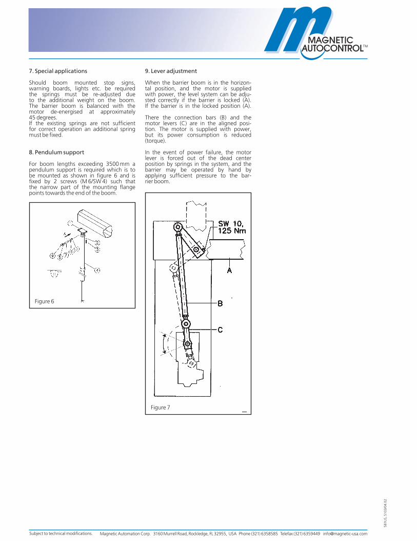
7. Special applications
Should boom mounted stop signs,warning boards, lights etc. be requiredthe springs must be re-adjusted dueto the additional weight on the boom.The barrier boom is balanced with themotor de-energised at approximately45 degrees.If the existing springs are not sufficientfor correct operation an additional springmust be fixed.
8. Pendulum support
For boom lengths exceeding 3500 mm apendulum support is required which is tobe mounted as shown in figure 6 and isfixed by 2 screws (M 6/SW 4) such thatthe narrow part of the mounting flangepoints towards the end of the boom.
9. Lever adjustment
When the barrier boom is in the horizon-tal position, and the motor is suppliedwith power, the level system can be adju-sted correctly if the barrier is locked (A).If the barrier is in the locked position (A).
There the connection bars (B) and themotor levers (C) are in the aligned posi-tion. The motor is supplied with power,but its power consumption is reduced(torque).
In the event of power failure, the motorlever is forced out of the dead centerposition by springs in the system, and thebarrier may be operated by hand byapplying sufficient pressure to the bar-rier boom.
581U
S, 5
103/
04.0
2
Figure 6
Figure 7
Subject to technical modifications. Magnetic Automation Corp. 3160 Murrell Road, Rockledge, FL 32955, USA Phone (321) 6358585 Telefax (321) 6359449 [email protected]

580U
S,51
65/0
/01.
00
MUB
Dimensional Diagram MUB
Control unitsMAGTRONIC
Info number: MF 5165/US
MUB Control Equipment
The MUB microprocessor control unitcan be used with all Magnetic barrierswith manual or automatic operation. Thebarrier is opened and closed by use ofspecial operator panels, or a customerinstalled pulse generator with potential freecontacts.For external equipment, there is a 24 VoltDC supply output (maximum 200 mA).Triac switching of the barrier motorprovides maintenance-free service.
Technical
The complete controller is contained inan isolated plastic housing. If required,rapid and easy replacement is possibleby means of two removeable terminalstrips on a standard mounting rail.Three rotary switches located on the toppanel control the mode (function) settingthe torque time (max. 15 seconds) andthe hold open time (max. 75 seconds).The indication of the active signal en-tries, barrier boom position (up/down)and the torque operation is achievedthrough built in LED’s.
After every power failure, or every func-tion change, it is recommended to„RESET“.
Mode 1:(Maintained contact function 100)The barrier is controlled by a potential-free switch. Contact closed = barrier„closed“.
Mode 2:(Dead man function 200)To open the barrier, merely press thekey „open“. The key „close“ must beoperated until the barrier has reachedits lowest limit. If the key is released priorto this, the barrier will open again.For the feedback of the position „closed“a limit switch is necessary (terminal19 and 23).
Mode 3:(Pulse control function 300)The barrier position is controlled by puls-es from a push-button. Each pulse resultsin a directional change (up/down) of thebarrier boom.
Mode 4:(Pulse control function 350)The barrier position is controlled by puls-es from two separate push buttons. Onefor „up“ and one for „down“.
Mode 5:(Dynamic function 400)The barrier is opened by a pulse andcloses automatically after an adjustablehold-open-time or immediately after thesafety device has been passed or after aclosing pulse has been given. As safetydevice an induction loop for examplemust be installed under the barrierboom. Closing is prevented as long as avehicle is positioned in the detectionarea.
Mode 6:(Same function as mode 5)When using a safety loop and an openingloop the loops are detecting the direc-tion of the traffic, i. e. the barrier closesimmediately after the safety loop hasbeen passed.
Mode 7:(Static function 500)Like mode 5 function 400, but withoutautomatic closing after a specified hold-
open-time. The barrier remains open until avehicle has activated the safety device andonly closes after it has left the detectionarea.
Mode 8:(Same function as mode 7 with additionaldetection of direction, see mode 6.)
Detection
If a vehicle is in the barrier boom area,closing can be prevented by connectionof the safety loop detection system to theterminal 19 and 24.(Normally closed contact.)The detector MID 1A-100 is recommend-ed for use with induction loops that areinstalled in the ground.In the event that no detection is desired awire bridge must be connected betweenterminals 19 and 24.
Electronic Braking
To increase the lifetime of the mecha-nism of a barrier with short opening andclosing times of under 2 seconds, anelectronic braking action can be appliedjust prior to reaching the end position ofthe up and down actions. A braking limitswitch with two trip cams is required(terminal 19 and 23).The braking function is not possible inMode 2 (Deadman).
Count Pulse
A potential-free pulse (300 ms) is givento terminals 31 and 32, after a vehicleopens and passes the closing detectiondevice.
Connection
All connections can be made to theexternally mounted terminal strips. Allfunction inputs and status signalsoperate at a safe voltage level and areseparated by optocouplers. The connec-tions for the motor and capacitors carry a115 Volt potential.
Functions
The factory sets the mode (function) bythe customer’s requirements. By turningthe rotary-switches this function may bechanged at a later date.
Magnetic Automation Corp. 3160 Murrell Road, Rockledge, FL 32955, USA Phone (321) 6358585 Telefax (321) 6359449 [email protected]

Subject to technical modifications.
Connection Mode 1
Connection Mode 4
Connection Mode 2
Connection Mode 5 and 6
Connection Mode 3
Connection Mode 7 and 8
Connection control panel MKI 6P-150
Connection control panel MKI 6P-175
switc
h op
en/c
lose
brak
e lim
it sw
itch
safe
ty d
evic
e
limit
switc
h fo
rsa
fety
dev
ice
push
-but
ton
open
push
-but
ton
clos
e
limit
switc
h
safe
ty d
evic
e
limit
switc
h fo
rsa
fety
dev
ice
push
-but
ton
open
/clo
se
brak
e lim
it sw
itch
safe
ty d
evic
e
limit
switc
h fo
rsa
fety
dev
ice
push
-but
ton
open
push
-but
ton
clos
e
brak
e lim
it sw
itch
safe
ty d
evic
e
limit
switc
h fo
rsa
fety
dev
ice
push
-but
ton
open
open
ing
loop
push
-but
ton
clos
e
brak
e lim
it sw
itch
safe
ty d
evic
e
limit
switc
h fo
rsa
fety
dev
ice
push
-but
ton
open
open
ing
loop
push
-but
ton
clos
e
brak
e lim
it sw
itch
safe
ty d
evic
e
limit
switc
h fo
rsa
fety
dev
ice
Connection MUB
redbluewhite
yellowgreen
connectioncontrol panelmode 3, 5 or 7
redbluewhitegreyyellowgreen
connectioncontrol panelmode 2, 4, 5 or 7
Magnetic Automation Corp. 3160 Murrell Road, Rockledge, FL 32955, USA Phone (321) 6358585 Telefax (321) 6359449 [email protected]

Magnetic Automation Corp. 3160 Murrell Rd Rockledge, FL 32955 Phone: (001) 321-635-8585 Fax: (001) 321-635-9449 E-mail: [email protected] Web: www.ac-magnetic.com
Presence vehicle detection for parking control and gate/barrier applications
Special characteristics:
• Plastic housing with compact size to be mounted directly on DIN - or C-rail • Direct cabling, no plug socket • Microprocessor controlled • Isolation transformer between loop and detector electronics • Automatic Calibration when switching on or when changing the adjustment of holding time • Adjustment of unlimited holding time possible • Indication with LED`s • All adjustments with DIP - switch on front panel • Adjustments of relay operation principle • Low voltage supply, AC or DC supply possible • Direction detection adjustable • Permanent or pulse output adjustable
MID2E - 800 Induction Loop Detector Dual Channel Detector Directional Detection

Magnetic Automation Corp. 3160 Murrell Rd. Rockledge, FL 32955 Phone: (001) 321-635-8585 Fax: (001) 321-635-9449 E-mail: [email protected] Web: www.ac-magnetic.com
Technical Data Power supply: 24 V AC/DC, +/- 10 % Power consumption: max. 1,5 W Temperature range: -20°C - +70°C Max. humidity max. 95%, not condensing Loop inductance range: 25 - 800 µH Frequency range: 30 - 130 kHz Sensitivity range (df / f): 0,01% - 0,65% in 4 steps Loop lead-in: max. 250 m Output relays: 1 relay with contact n.o. per channel pulse output at leaving of loop adjustable for channel 2. relay operation principle: rest operation/current operation /contact n.c./contact n.o. adjustable with jumper or solder strap on circuit board Switch voltage: 24 V AC/DC Housing plastic-clamp enclosure for shelf or DIN-rail socket with 2x 3-pin. clamps Dimensions: 79 x 22,5 x 90 mm (h x w x d) Protection class: IP 40 (waterproofed) Terminal connection Terminal screws on top Terminal screws on bottom signature function signature function 0V power supply (neutral) 1a common – channel 1 24V power supply (24V AC/DC) 1b contact n.o - channel 1 2b contact n.o - channel 2 2a common – channel 2
DIP-switch modes 1 2 3 4 5 6 7 8 function off off - - - - - - sensitivity channel 1 - step 1 (low) on off - - - - - - sensitivity channel 1 - step 2 (med. low) off on - - - - - - sensitivity channel 1 - step 3 (med. high) on on - - - - - - sensitivity channel 1 - step 1 (high) - - off off - - - - sensitivity channel 2 - step 1 (low) - - on off - - - - sensitivity channel 2 - step 2 (med. low) - - off on - - - - sensitivity channel 2 - step 3 (med. high) - - on on - - - - sensitivity channel 2 - step 1 (high) - - - - off - - - frequency low - - - - on - - - frequency high - - - - - off - - holding time 5 minutes - - - - - on - - holding time unlimited - - - - - - off - presence detection - - - - - - on - direction detection - - - - - - - off output permanent signal (both relays) - - - - - - - on output pulse signal at leaving of loop – only channel 2 or direction pulse output (if DIP7=on) (off = left switch position) (on = right switch position)
Function of LED’s LED green LED red function off off power off flash off detector calibrates on off detector ready for operation, loop free on on detector ready f. operation, loop occupied off on loop failure pulse - loop frequency by pulse signal
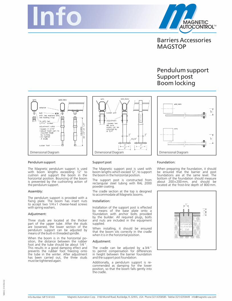
Pendulum support
The Magnetic pendulum support is usedwith boom lengths exceeding 12’ tocushion and support the boom in thehorizontal position. Bouncing of the boomis prevented by the cushioning action ofthe pendulum support.
Assembly:
The pendulum support is provided with afixing plate. The boom has insert nutsto accept two 1/4 x 1 cheese-head screwswith spring washers.
Adjustment:
Three studs are located at the thickerpart of the upper tube. After the studsare loosened, the lower section of thependulum support can be adjusted bymeans of the built-in threaded spindle.
When the boom is in the horizontal po-sition, the distance between the rubberfoot and the tube should be about 1/4 ”.This results in a good damping effect andprevents the rubber foot freezing ontothe tube in the winter. After adjustmenthas been carried out, the three studsmust be tightened again.
Support post
The Magnetic support post is used withboom lengths which exceed 12’, to supportthe boom in the horizontal position.
The support post is constructed fromrectangular steel tubing with RAL 2000powder coating.
The cradle section at the top is designedto accommodate all Magnetic booms.
Installation:
Installation of the support post is effectedby means of the base plate onto afoundation with anchor bolts providedby the builder. All required plugs, boltsand nuts are included in the equipmentsupplied.
When installing, it should be ensuredthat the boom sits correctly in the cradlewhen it is in the horizontal position.
Adjustment:
The cradle can be adjusted by ± 3/4 “to permit compensation for differencesin height between the barrier foundationand the support post foundation.
Additionally, a pendulum support is re-commended as damping for the lowerposition, so that the boom falls gently intothe cradle.
Foundation:
When preparing the foundation, it shouldbe ensured that the barrier and postfoundations are at the same level. Thebottom of the foundation should measureabout 200 x 200 mm, and should belocated at the frost-line depth of 800 mm.
Barriers AccessoriesMAGSTOP
Pendulum supportSupport postBoom locking
Info-Number: MF 5141/US
Dimensional Diagram Dimensional Diagram Dimensional Diagram
580U
S, 5
141/
04.0
2
Magnetic Automation Corp. 3160 Murrell Road, Rockledge, FL 32955, USA Phone (321) 6358585 Telefax (321) 6359449 [email protected]

Boom locking
The Magnetic boom lock offers optimumprotection against forcible opening ofthe barrier boom.
The lock is installed inside the barrierboom with the electrical leads passingthrough the boom and into the barrierhousing which ensures protectionagainst corrosion, misuse or vandalism.
During the position ”Off“, as shown infigure 1, the lock is energized with theresultant warmth, from the solenoid,preventing condensation and corrosion,thus ensuring reliable operation, partic-ularly in winter.
Subject to technical modifications.
In case of power failure the device locksautomatically, as shown in figure 2; thebarrier boom can be opened manually asshown in figure 3.
To ensure correct functioning of the lockthe barrier boom must not rest heavilyon the support pillar. If necessary thelocking plate or barrier boom must bere-adjusted.
For the installation, adjustment andguidelines for the foundations pleaserefer to the leaflet on the supportingpillar.
Control Unit MMV
The control unit, figure 4, was develop-ped to control the lock and can be com-bined with all Magnetic control units asshown in figure 5. It is mounted, andwired, on the hinged mounting plate andis adjusted at the factory.
The lock can be altered to suite localrequirements, or boom lengths, with thetime adjusted by the potentiometer onthe front panel.
The locking time is 10 seconds after theboom closes.
Fig. 1
Fig. 2
Fig. 3
Fig. 4
Fig. 5
Dimensional Diagram
Dimensional Diagram
Magnetic Automation Corp. 3160 Murrell Road, Rockledge, FL 32955, USA Phone (321) 6358585 Telefax (321) 6359449 [email protected]

Info number: MF 5117/US
General
Barrier installations which close automatic-ally utilise induction loops, to detect appro-aching vehicles.The following points should be taken intoaccount when laying induction loops.
1. The loop should be laid symmetricallywith respect to the boom. When deter-mining the layout of the loop, it should be remembered that the boom is fixed to the barrier housing at one side.
2. The detection loop should be situatedso that there is a distance of at least2 1/2’ behind, and in front of the boom. Inspecial cases it is possible to deviate fromthis value by agreement with the factoryif a smaller detection area is required.
3. The distance from the barrier housingand the end of the boom should beapprox. 1’ from the induction loop.
4. When concreting in or laying the loop, itshould be ensured that the loop cannotmove while in operation. Any geometri-cal changes result in inductance chan-ges, causing interference to the detec-tor.
5. Where iron reinforcement is used, itshould be ensured that a minimumspacing of 1’ exists. Iron reinforcementproduces fundamental attenuation andreduces the sensitivity of the detector.
6. For checking purposes, a volume re-sistance < 2 Ohm and an insulation re-sistance with respect to earth > 1 MOhmmust be measured after the loop is laid.Otherwise there is a defect in the loop.
Laying in bitumen/asphalt
For installation in this type of sub-surface,a 11/2” deep channel must be cut with agrinding wheel. It must be ensured thatthe cuts overlap at the corners so thatthe same depth is achieved at every point.
The loop must then be laid carefully in thechannel and pressed down with a piece ofwood. Under no circumstances must theinsulation be damaged.
The channel is then sealed with a castingcompound. The temperature of the castingcompound must not exceed 212° F duringthe reaction.
Induction loops are available as ready-madecables with the following dimensions
KAS 1 loop periphery 20’KAS 2 loop periphery 40’KAS 3 loop periphery 68’KAS 4 loop periphery 30’KAS 5 loop periphery 50’
In all cases the feed line measures a max.of 150’. Under no circumstances must it be used in rolled form, but it must be cutto the required length on site.
Barrier AccessoriesMAGSTOP
Loop installationinstructions
580U
S, 5
117/
04.0
2
300
300
�1��2��3
S0103
min. 500500
2530
50
300150
1
2
3
54
6
S0104
leadchannel top view�
edges cut diagonally
laging of inductionloop�
top view
lead
1 Access lane2 Induction loop3 Projection of the barrier boom over the surface of
the lane, assuming standard loop installation
1 Barrier housing 2 Channel with sealing compound3 Asphalt covering4 Glass sand layer5 Loop cable6 Concrete foundation
Magnetic Automation Corp. 3160 Murrell Road, Rockledge, FL 32955, USA Phone (321) 6358585 Telefax (321) 6359449 [email protected]

Alternatively, you can make up a loop your-self from 0,75–1,5 mm2 single core wire.Ensure that the inductance is between 70and 500 mH. This can usually be achievedby means of 3 to 5 windings. The feed linemust be twisted at least 20 times permeter. The same installation data apply asfor the ready-made loops.
Laying under composite slabs
In this case the ready-made loop must beused. It must be ensured that the loop islaid in a sand bed and cannot be dama-ged. A sand layer of about 30 mm must bepresent between the slabs and the loop.
Subject to technical modifications.
30
300150
1
2
345
S0105
2530
50
300150
1
2
3
54
6
S0104
1 Barrier housing 2 Paving stones3 Loop cable4 Sand bed5 Concrete foundation
1 Barrier housing 2 Channel with sealing compound3 Asphalt covering4 Glass sand layer5 Loor wire6 Concrete foundation
Magnetic Automation Corp. 3160 Murrell Road, Rockledge, FL 32955, USA Phone (321) 6358585 Telefax (321) 6359449 [email protected]


preventative maintenance report 10/27/06
Preventative Maintenance for Magnetic MAGSTOP barriers type MTS6/8-900 Technical Data: Max.barrier width 27.0 FT Opening/closing time 6.5 sec. Voltage V 115.0 V Frequency 60 Hz. Power Consumption 280.0 W Housing width 18.5 Inch depth 14.5 Inch height 43.0 Inch Weight excluding boom 298.0 Lbs Motor SAM210-24 Capacitors C1 30µF/C2 20µF Technology: The combination of our patented torque motor and a sinusoidal lever system represents a simple drive system with high reliability. This drive system permits fast opening and closing times without “bouncing” of the boom in the end positions. The sinusoidal lever system ensures that the boom is locked in both end positions. In the event of power failure it can easily be moved by hand or adjustments for a boom length up to 20FT for automatically opening in power failure is possible. The boom weight is exactly balanced by means of built-in springs. Adjustment to the appropriate boom length is carried out at the factory before delivery. Modifications such as shortening of the boom or the attachment of sign-boards or any kind of weight, as long it doesn’t exceed the weight limit, can be adjusted without difficulty on site during installation.

preventative maintenance report 10/27/06
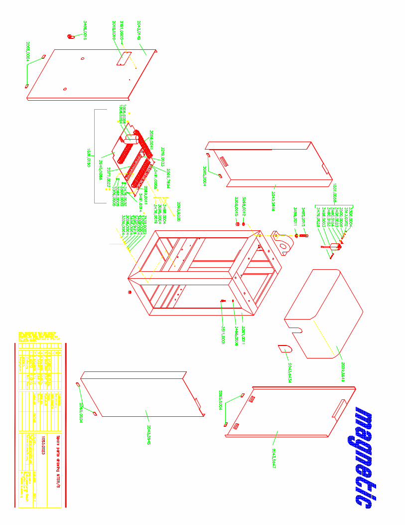
Drive: The heart of the Magnetic barriers is the 115V AC patented blockable torque motor. It requires neither limit switches nor a slip clutch and is maintenance free. The motor can be blocked in any position without causing damage. In both end positions, the motor stops with the voltage still applied, and locks the boom via the sinusoidal lever system. In both end positions the motor-power is reduced to about 15W to economize on operating costs. The heat generated by the torque motor prevents condensation and corrosion, ensuring reliable and problem-free operation particularly in cold climatic conditions. Horizontal and vertical position alignment of barrier arm: Please refer to drawing # 1053.0023 and # 1053.0079 1. Move gate arm to the up position and turn power off. 2. Use keys to open front panel (2043.0149). 3. Fold down aluminum controller board and open 3 wing screws (3511.0001) in
order to take off the housing lid . 4. Hold boom in up position firmly and open the 2 (two) socket head cap screws
which clamp the spring lever (# 2056.6474) to the flange shaft (#3484.0040) with a 10 mm hex key wrench, so you are able to move the gate arm to the desired position .
5. Tighten the 2 (two) socket head cap screws with a tightening moment of 125Nm -90ft/lbs.
6. Two people are required to do this adjustment, one holding the boom the other opening and tightening the screws.

preventative maintenance report 10/27/06
90 degree alignment of gate arm operating angle: Please refer to drawing # 1053.0023 and # 1053.0079 1. Move gate to up position and turn power off. 2. Use keys to open front panel (2043.0149). 3. Fold down aluminum controller board and open 3 wing screws (3511.0001) in
order to take the housing lid off. 4. Take off back panel ( 2043.5947) and both side panels ( 2043.5945/2043.5946). 5. Turn power back on and move gate arm to down position 6. Loosen the 2 (two) hex nuts ( LH and RH tread) on each end of the 2 (two)
connecting rods (Figure 7 part B). 7. Turning the connecting rods clockwise increase the boom arm movement angle,
counter clockwise reduces the angle of movement 8. Both connecting rods (part B) have to be turned at the same time. 9. The distance between the center of the mounting holes of the two universal
bearings ( # 3146.0010) has to be the same on both sides. 10. Adjust the barrier arm by turning the connecting rods past the desired horizontal
position. Then move the boom to the up position. Follow instructions Alignment of horizontal and vertical position of barrier arm: 1-7 This will automatically compensate for the horizontal adjustment.
11. Tighten the 4 (four) hex nuts.

preventative maintenance report 10/27/06
Adjustment for automatic opening in the event of power failure: Please refer to drawing # 1053.0023 and # 1053.0079 1. Remove the barrier lid and all panels. 2. Move gate arm to down position 3. Loosen the socket head cap screw which clamps the motor lever(C) 4. Adjust connecting rod (A) and motor lever(B) so there is a approximately 3˚
deflection towards the rear of the barrier. This will move the lever system so that it is out of the in line adjustment (locked).
5. Tighten the socket head cap screw with a torque moment of 125Nm-90ft/lbs. 6. Repeat the same steps on the second connecting rod. 7. Do not loosen both motor levers at the same time. 8. Adjust the springs accordingly, so that the tension of the springs pulls the gate
arm from the horizontal position, in the event of a power failure. Adjust the springs by turning the M8 hex nuts attached to the springs. Clockwise = lower tensioning of springs/counter clockwise = higher tensioning of springs.

preventative maintenance report 10/27/06
Maintenance schedule: A Monthly
Check barrier arm alignment in horizontal and vertical position. Adjust levers if necessary.
B Annually 1. Check spring tension adjustment to ensure boom arm raises on power failure. 2. Lubricate flange bearings. Recommended grease Tribol 3020/1000-2 DIN 51502. 3. Check electrical connections.