operating instructions for omarlift hydraulic components
TRANSCRIPT
All right are reserved. Copy forbidden, even partial Subject to change without notice!
D840MGB Rev.02_20171030.docx
OPERATING INSTRUCTIONS FOR
OMARLIFT HYDRAULIC COMPONENTS


All right are reserved. Copy forbidden, even partial Subject to change without notice!
D840MGB Rev.02_20171030.docx
Content
GENERAL INFORMATION PREVIOUS TO THE INSTALLATION ............................................................................................ 1-1 1
INTRODUCTION ........................................................................................................................................................ 1-1 1.1
LIABILITY AND GUARANTEE ...................................................................................................................................... 1-1 1.2
SAFETY MEASURES ................................................................................................................................................... 1-1 1.3
WARNING ON HOW TO OPERATE ............................................................................................................................ 1-1 1.4
SAFETY ON THE WORKING PLACE .................................................................................................................... 1-1 1.4.1
CLEANING ........................................................................................................................................................ 1-2 1.4.2
INSTALLATION .................................................................................................................................................. 1-2 1.4.3
MAINTENANCE ................................................................................................................................................ 1-2 1.4.4
ANTI-POLLUTION MEASURES ........................................................................................................................... 1-2 1.4.5
CONTROL OF THE SUPPLIED MATERIAL .................................................................................................................... 1-3 1.5
IDENTIFICATION PLATES ........................................................................................................................................... 1-3 1.6
FEATURES OF THE MACHINE ROOM ........................................................................................................................ 1-3 1.7
TRANSPORT AND STORAGE OF THE HYDRAULIC COMPONENTS ...................................................................................... 2-1 2
GENERAL INFORMATION .......................................................................................................................................... 2-1 2.1
CYLINDERS ................................................................................................................................................................ 2-1 2.2
PUMP UNITS ............................................................................................................................................................. 2-2 2.3
FLEXIBLE HOSES AND RIGID PIPES ............................................................................................................................ 2-3 2.4
ASSEMBLING OF THE HYDRAULIC COMPONENTS ............................................................................................................. 3-1 3
CYLINDER .................................................................................................................................................................. 3-1 3.1
ASSEMBLING OF THE SIDE ACTING CYLINDERS, ROPED 2:1 O 1:1 ................................................................... 3-2 3.1.1
ASSEMBLING OF THE UNDERGROUND DIRECT ACTING CYLINDERS ................................................................ 3-3 3.1.2
GUIDE ARMS FOR TELESCOPIC CYLINDERS ...................................................................................................... 3-4 3.1.3
CYLINDERS IN TWO OR MORE PIECES .............................................................................................................. 3-4 3.1.4
CONTROL OF THE NEW CYLINDER ................................................................................................................... 3-6 3.1.5
PUMP UNIT ............................................................................................................................................................... 3-6 3.2
PIPE AND HYDRAULIC CONNECTIONS ...................................................................................................................... 3-6 3.3
CONNECTION OF INSTALLATIONS WITH TWO CYLINDERS ....................................................................................... 3-8 3.4
ELECTRICAL CONNECTIONS ............................................................................................................................................... 4-1 4
GENERAL REGULATIONS ........................................................................................................................................... 4-1 4.1
CONNECTION BOX .................................................................................................................................................... 4-1 4.2
ELECTRICAL CONNECTION OF THE THREE-PHASE MOTOR ....................................................................................... 4-2 4.3
ELECTRICAL CONNECTION OF THE SINGLE PHASE MOTOR ...................................................................................... 4-2 4.4
MOTOR PROTECTION WITH THERMISTORS ............................................................................................................. 4-3 4.5
ELECTRICAL CONNECTION OF THE VALVE GROUP ................................................................................................... 4-3 4.6

All right are reserved. Copy forbidden, even partial Subject to change without notice!
1-2 D840MGB Rev.02_20171030.docx
VALVES FOR DIRECT START .............................................................................................................................. 4-5 4.6.1
OIL FOR LIFTS – CIRCUIT FILLING AND AIR PURGING ........................................................................................................ 5-1 5
CHARACTERISTICS AND CHOICE OF THE OIL ............................................................................................................ 5-1 5.1
CIRCUIT FILLING AND AIR PURGING ......................................................................................................................... 5-3 5.2
FILLING AND SYNCHRONISATION OF TELESCOPIC CYLINDERS ................................................................................. 5-5 5.3
CONTROL AND TESTS ........................................................................................................................................................ 6-1 6
CHECK OF THE OIL LEVEL IN THE TANK..................................................................................................................... 6-1 6.1
CHECK OF THE MAX. PRESSURE................................................................................................................................ 6-1 6.2
CHECK OF THE START IN UPWARD DIRECTION ........................................................................................................ 6-1 6.3
CHECK OF THE SEALING OF SEALS AND PIPES .......................................................................................................... 6-1 6.4
CHECK OF THE RUPTURE VALVE INTERVENTION ...................................................................................................... 6-1 6.5
CHECK OF THE INSTALLATION AT TWICE THE STATIC PRESSURE ............................................................................. 6-1 6.6
CHECK OF THE ROD COUNTER-PRESSURE AND HAND MANOEUVRE....................................................................... 6-2 6.7
CHECK AND ADJUSTING OF THE HAND PUMP ......................................................................................................... 6-2 6.8
CHECK OF THE TIME DURING WHICH THE MOTOR IS UNDER TENSION .................................................................. 6-2 6.9
CHECK OF THE MOTOR AND THERMISTOR PROTECTION......................................................................................... 6-2 6.10
NOISE ........................................................................................................................................................................ 6-3 6.11
MANOMETER SHUT-OFF .......................................................................................................................................... 6-3 6.12
ADJUSTING AND TEST OF THE RUPTURE VALVE ............................................................................................................... 7-1 7
GENERAL INFORMATION .......................................................................................................................................... 7-1 7.1
ADJUSTING OF THE RUPTURE VALVE ....................................................................................................................... 7-1 7.2
TEST AND WORKING OF THE RUPTURE VALVE......................................................................................................... 7-3 7.3
ADJUSTING AND REGULATION OF “NL” VALVE GROUP .................................................................................................... 8-1 8
GENERAL INFORMATION .......................................................................................................................................... 8-1 8.1
ADJUSTING AND REGULATION OF “NL” VALVE GROUP ........................................................................................... 8-1 8.2
ADJUSTING OF THE OVER-PRESSURE VALVE: SCREW N°1 ............................................................................... 8-4 8.2.1
ADJUSTING OF THE START IN UPWARD DIRECTION: SCREW N°7 .................................................................... 8-4 8.2.2
REGULATION OF THE LOW SPEED: SCREW N°2 ............................................................................................... 8-4 8.2.3
ADJUSTING OF THE UPWARD SPEED: SCREW N°6 ........................................................................................... 8-5 8.2.4
ADJUSTING OF THE MAX DOWNWARD SPEED – SCREW N°8 .......................................................................... 8-5 8.2.5
REGULATION OF THE DECELERATION FROM HIGH TO LOW SPEED: SCREW N°5 ............................................ 8-5 8.2.6
ROD COUNTER-PRESSURE AND ROPE ANTI-LOOSENING: SCREW N°3 ............................................................ 8-5 8.2.7
ADJUSTING OF THE HAND PUMP PRESSURE: SCREW N°9 ............................................................................... 8-6 8.2.8
ADJUSTING OF THE PRESSURE SWITCHES (PRESSURE: MIN. – MAX. – OVERLOAD) ....................................... 8-7 8.2.9
DIAGRAMS: VALVE NL, VP RUPTURE VALVE .................................................................................................... 8-8 8.2.10
OPTIONALS ACCESSORIES ................................................................................................................................................. 9-1 9

All right are reserved. Copy forbidden, even partial Subject to change without notice!
D840MGB Rev.02_20171030.docx
VALVE HEATING RESISTOR ....................................................................................................................................... 9-1 9.1
OIL HEATING RESISTOR ............................................................................................................................................. 9-1 9.2
OIL COOLING............................................................................................................................................................. 9-2 9.3
GENERAL INFORMATION ................................................................................................................................. 9-2 9.3.1
COOLING SYSTEM WITH AIR ............................................................................................................................ 9-2 9.3.2
COOLING SYSTEM WITH WATER ...................................................................................................................... 9-3 9.3.3
MICRO-LEVELLING UPWARD WITH SUBSIDIARY MOTOR ......................................................................................... 9-4 9.4
MAINTENANCE OF THE HYDRAULIC INSTALLATION ................................................................................................... 10-1 10
GENERAL INFORMATION ........................................................................................................................................ 10-1 10.1
OIL LOSSES AND CAR LOWERING ........................................................................................................................... 10-1 10.2
LOSSES ALONG THE PIPES .............................................................................................................................. 10-1 10.2.1
CYLINDER LOSSES ........................................................................................................................................... 10-1 10.2.2
LOSSES INSIDE THE VALVE GROUP ................................................................................................................ 10-2 10.2.3
SEAL REPLACEMENT ON A SINGLE-STAGE CYLINDER ............................................................................................. 10-5 10.3
AIR IN THE OIL ........................................................................................................................................................ 10-7 10.4
FILTER CLEANING INSIDE THE VALVE GROUP ......................................................................................................... 10-7 10.5
MINERAL OIL DETERIORATION ............................................................................................................................... 10-8 10.6
ELECTRICAL ANTI-CREEP SYSTEM .......................................................................................................................... 10-8j 10.7
EMERGENCY LOWERING WITH THE BATTERY ........................................................................................................ 10-8 10.8
PLATES, DIAGRAMS, INSTRUCTIONS ...................................................................................................................... 10-8 10.9
SEAL REPLACEMENT ON TELESCOPIC CYLINDERS .............................................................................................. 10-8 10.10
GENERAL INFORMATION ........................................................................................................................... 10-8 10.10.1
SEAL REPLACEMENT ON TWO-STAGE TELESCOPIC CYLINDERS, TYPE CT-2 ............................................... 10-9 10.10.2
SEAL REPLACEMENT ON THREE- STAGE TELESCOPIC CYLINDERS, TYPE CT-3.......................................... 10-11 10.10.3
POSSIBLE PROBLEMS AND THEIR SOLUTION ................................................................................................... 10-14 10.11
VALVE MODIFICATION: FROM DIRECT START TO – Δ FOR THE MOTOR ACTIVATION WITH SOFT STARTER OR 10.12
– Δ ......................................................................................................................................................................... 10-17
PERIODICAL RECOMMENDED MAINTENANCE SHEET ...................................................................................... 10-19 10.13
DIMENSIONS AND WEIGHTS – OIL FOR TELESCOPIC CYLINDERS ............................................................................... 11-1 11
DIMENSIONS AND WEIGHTS OF THE PUMP UNITS ................................................................................................ 11-1 11.1
DIMENSIONS AND WEIGHTS OF ONE-STAGE CYLINDERS ....................................................................................... 11-3 11.2
DIMENSIONS AND WEIGHTS OF THE TELESCOPIC CYLINDERS, FILLING OIL AND OIL FOR MOVEMENT ................ 11-4 11.3


All right are reserved. Copy forbidden, even partial Subject to change without notice!
D840MGB Rev.02_20171030.docx 1-1
GENERAL INFORMATION PREVIOUS TO THE INSTALLATION 1
INTRODUCTION 1.1
The assembly, installation, put into action and maintenance of the hydraulic lift have to be carried out only by
trained staff. Before starting with any kind of work on the hydraulic components, it is necessary that the trained
staff reads these operating instructions carefully; in particular chapters 1.3 “SAFETY MEASURES” and 1.4
“WARNING ON HOW TO OPERATE”. These “Operating instructions” are an integral part of the installation and
have to be kept in a safe and accessible place.
LIABILITY AND GUARANTEE 1.2
These operating instructions are addressed to staff competent in installing, adjusting and maintenance
operations on the hydraulic lifts.
Omar Lift does not take responsibility for any kind of damage caused by use different from the one hereby
explained, lack of experience, carelessness by people assigned to the assembling, repair operations of the
hydraulic components.
Omar Lift guarantee is not valid anymore if components or spare parts different from the original ones are
installed, and if modifications or repair operations are carried out by non-authorised or non-qualified workers.
SAFETY MEASURES 1.3
Installers and maintenance staff are fully responsible for their safety while working. All the safety measures in
force have to be observed carefully to prevent competent staff or any possible non-competent persons or
objects, from damages or accidents during the installation or maintenance works.
These operating instructions report some symbols, which correspond to important safety measures:
Danger: this symbol draws attention to high risk of injury of persons. It must always be obeyed.
Warning: this symbol draws attention to information which, if it is not observed, can lead to injury to persons or extensive damage to property. It must always be observed.
Caution: this symbol draws attention to information containing important instructions for use. Failure to observe the instructions can lead to damage or danger.
WARNING ON HOW TO OPERATE 1.4
Hereby follow the most important principles which always have to be observed while working on hydraulic
installations. These principles will not be repeated in the following chapters, because they are considered to be
known.
SAFETY ON THE WORKING PLACE 1.4.1
Lack of observing simple safety rules or lack of attention can lead to even severe incidents. In case of works on the hydraulic installation, it is necessary to:
Get the lift to be at the bottom directly on the buffer;
Block the main switch to be sure that the lift can not be put into service unintentionally;
Get the oil pressure to zero before opening any part of the hydraulic circuit, caps or unscrewing fittings;
Prevent cinders from getting in contact with oil, rod and its seal and all the elastic parts of the installation
during welding operations;

All right are reserved. Copy forbidden, even partial Subject to change without notice!
1-2 D840MGB Rev.02_20171030.docx
Get rid of the spilled oil, oil leakage, keep the installation always clean so that any leakage can be easily
detected.
CLEANING 1.4.2
Cinders and dirt inside the hydraulic installation cause bad working and precocious wear. Before assembling, it is
necessary to clean the different parts with a lot of care:
- All the possible protection caps, plastic bags and tape used for packing have to be removed;
- The connection pipes, whether they are flexible or iron have to be cleaned perfectly from the inside.
Especially the iron pipes have to be cleaned from the inside and cinders have to be removed from the ends. A
pipe bender, not flame, has to be used to bend the iron pipe;
- Before pouring the oil into the pump unit tank, check that no dirt or water is inside it;
- Use always a good filter to pour or add oil in the tank;
- For the cleaning of the pipes and the pump unit do not use fraying clothes or steel wool;
- The cylinder head and all the plastic or rubber parts have to be protected if paint, concrete or welding
machines are used in their neighbourhood;
- All the parts of the installation which have been disassembled to be tested or repaired, the sealing surfaces,
the pipes and the fittings have to be cleaned perfectly before being reassembled.
INSTALLATION 1.4.3
For the installation or the replacement of the hydraulic installation components, the following points have to be
observed:
- Only use the material advised by Omar Lift(especially the hydraulic oil) and the original Omar Lift spare parts;
- Avoid the use of sealing materials such as silicone, plaster or hemp which could penetrate the hydraulic
circuit;
- In case pipes bought directly from the market are being used, only choose the ones responding to the safety
measures in force and according to the pressure of the installation. Note that the only use of the iron pipe to
connect the pump unit to the cylinder can transmit and increase the noise;
- Install the flexible hoses with the right bending radius suggested by the manufacturers and avoid the use of
hoses which are longer than necessary.
MAINTENANCE 1.4.4
During the periodical works of maintenance besides normal tests, it should be remembered that:
- The damaged pipes have to be replaced immediately;
- Get rid of oil leakage and its causes;
- The possible spilled oil has to be collected, so that leakage can be easily detected;
- Be sure that there are no unusual and excessive noises in the pump, the motor or the suspensions. Get rid of
them.
ANTI-POLLUTION MEASURES 1.4.5
Possible spilled oil from the circuit during repair operations has not to be spread in the environment, but has not
to be promptly collected with cloths or sponges and disposed carefully in proper containers. In case of oil

All right are reserved. Copy forbidden, even partial Subject to change without notice!
D840MGB Rev.02_20171030.docx 1-3
replacement, also the waste oil has to be disposed in proper containers. For the disposal of oil and clothes
containing oil contact the specialised companies according to the regulations in force in the country of operation.
Concerning the rules against the water pollution (see underground direct acting installations with high quantities
of oil act according to the national rules.
CONTROL OF THE SUPPLIED MATERIAL 1.5
When the material is withdrawn before signing the delivery document of the forwarding agent, check that the
goods correspond to the list reported in the delivery document and to the requested order.
IDENTIFICATION PLATES 1.6
The main supplied components have their own plate containing all the data needed to identify them:
- Cylinder: adhesive plate on the cylinder head;
- Rupture valve: plate fixed on the valve side;
- Pump unit: plate fixed on the tank cover;
- Flexible hose: test date, test pressure and manufacturer name engraved on the fitting.
FEATURES OF THE MACHINE ROOM 1.7
Before installing:
- Make sure that the shaft, pit, head and machine room correspond to the project data and respond to the
regulations in force, and:
- Make sure that access ways allow the passage of the different components to be installed;
- Make sure that the bottom of the pit is clean, dry and waterproof;
- Make sure that the shaft is ventilated and illuminated sufficiently;
- Make sure that the machine room has the access door with opening towards the outside, if possible noise-
proof, well-ventilated and its temperature preferably between 10 and 30°C.

All right are reserved. Copy forbidden, even partial Subject to change without notice!
D840MGB Rev.02_20171030.docx 2-1
TRANSPORT AND STORAGE OF THE HYDRAULIC COMPONENTS 2
GENERAL INFORMATION 2.1
For the transport and the storage of the hydraulic components, the general safety regulations always have to be
followed:
When loads have to be lifted, only use proper hoists and respect their max. capacity.
Never walk or stop under the hanging loads.
Avoid hydraulic components from shocks.
- If the hydraulic components have to be stored, first control that packaging and protections are in a perfect
state; if necessary repair or replace them with other more suitable ones;
- Store the hydraulic components in a dry place, dust free with a temperature between 5 and 30°C;
- If the cylinders or the pump units have to be stored for a long time, it is better for the preservation to fill
them with oil.
CYLINDERS 2.2
The cylinder rod is blocked against the cylinder with a stirrup so that it can not get off during any moving or
transport. In the cylinders in two pieces, the joints are protected by two protection flanges, blocked against the
cylinder flanges with two screws. The two protection flanges are needed to keep the two parts of the rod
blocked, avoiding water and dirt from getting inside it.
TRANSPORT OF THE CYLINDER
The loading and unloading on the means of transport have to be made with proper hoists or clamp trucks.
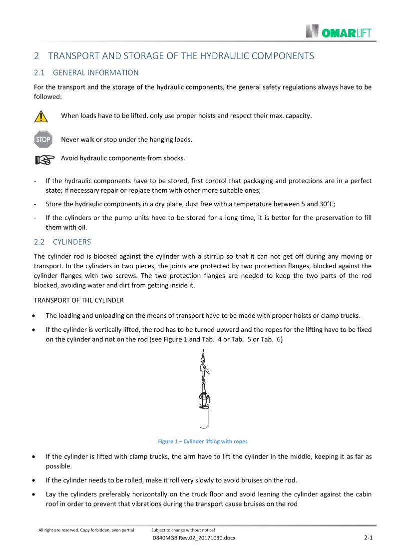
If the cylinder is vertically lifted, the rod has to be turned upward and the ropes for the lifting have to be fixed
on the cylinder and not on the rod (see Figure 1 and Tab. 4 or Tab. 5 or Tab. 6)
Figure 1 – Cylinder lifting with ropes
If the cylinder is lifted with clamp trucks, the arm have to lift the cylinder in the middle, keeping it as far as
possible.
If the cylinder needs to be rolled, make it roll very slowly to avoid bruises on the rod.
Lay the cylinders preferably horizontally on the truck floor and avoid leaning the cylinder against the cabin
roof in order to prevent that vibrations during the transport cause bruises on the rod

All right are reserved. Copy forbidden, even partial Subject to change without notice!
2-2 D840MGB Rev.02_20171030.docx
STORAGE OF THE CYLINDERS
Before storing, check that the protection packaging is in a perfect state of preservation.
After having positioned the cylinders on proper supports, block them in a way that they can not fall.
If cylinders in one piece have to be stored for a long time, it is better to fill them with anticorrosive oil. Since
the oil volume increases or decreases according to the temperature, it is better not to fill the cylinders
completely.
If cylinders in two pieces have to be stored for a long time, check that the flanges closing the joint close
hermetically and that the rods are well greased. Keep both the closing flanges and the rod which comes out
from the cylinder covered well with grease.
Before putting the installation into action, replace the oil used for the filling up and remove the excessive
grease.
PUMP UNITS 2.3
The pump unit is protected by a thermos-shrinking plastic cover and lays on a wooden support.
In case customers ask, the pump unit can be packed in resistant cardboard or in a wooden cage.
TRANSPORT OF PUMP UNITS
Load and unload the pump units using clamp trucks. If the pump unit has to be lifted with ropes, make them pass under the handles (see Figure 2 and Tab.3)WEIGHTS OF THE PUMP UNITS
The pump units can not be placed on each other.
Figure 2 – Pump unit lifting with ropes
STORAGE OF THE PUMP UNITS
TANK TYPE PUMP UNIT WEIGHT (OIL EXCLUDED) Kg
110 105
210 145
320 176
450 230
680 300

All right are reserved. Copy forbidden, even partial Subject to change without notice!
D840MGB Rev.02_20171030.docx 2-3
Store the pump units in a dry place with a temperature between 5 and 30°C.
Control the protection packaging and replace it if necessary.
If the pump units have to be stored for a long time, it is better to fill the tank with oil, at least until the
electrical motor is covered.

All right are reserved. Copy forbidden, even partial Subject to change without notice!
2-4 D840MGB Rev.02_20171030.docx
FLEXIBLE HOSES AND RIGID PIPES 2.4
PIPES TRANSPORT
Avoid harsh bending of the flexible hoses.
Prevent the flexible hoses from contact with caustic essences, solvents or other chemical substances.
Transport the flexible hoses in their original packaging.
Avoid any kind of bending of the rigid pipes.
Transport the rigid pipes with their caps on the ends.
STORAGE OF THE PIPES
Store the pipes in a dry place, with a temperature between 5 and 30°C.
Prevent the flexible hoses from the direct sunlight or the near presence of a heat source.
Do not keep the flexible hoses stored for more that 2 years from the test date engraved on the fitting.

All right are reserved. Copy forbidden, even partial Subject to change without notice!
D840MGB Rev.02_20171030.docx 3-1
ASSEMBLING OF THE HYDRAULIC COMPONENTS 3
CYLINDER 3.1
The cylinder serial number is indicated by a label on the cylinder head, on the same side where is fixed the
rupture valve. On the label are shown also other data of the cylinder (see Figure 3).
Figure 3 - Serial number and identification plate of the cylinder
- All the cylinders, both those in one piece those in two pieces, are tested in the factory at two levels of
pressure to guarantee the sealing of the seals and the sealing of the welding;
- Telescopic cylinders have to undergo not only the pressure tests but also tests regarding the synchronisation
and the travel length of the different stages;
- The oil used for tests is then taken out of the cylinder. The small quantity which remains inside acts as a
protection against rust for a long period of time. If the cylinder remains on the site for a long time, it is better
to control the state of preservation of the rod, cleaning and polishing it, if necessary. For long periods of
storage see point 2.2;
- The oil inlet (and therefore the rupture valve) can be at the top or at the bottom; the oil inlet has to be
decided when ordering;
Depending on the length of the cylinder the kit for rod protection can be supplied in order to avoid impacts during transport. Before put into service, remove 3 screws and replace them with the 3 caps supplied before oil filling.
Figure 4 – Removal kit rod protection

All right are reserved. Copy forbidden, even partial Subject to change without notice!
3-2 D840MGB Rev.02_20171030.docx
- The rupture valve, assembled directly on the cylinder by the Installer and can be oriented in four directions
with 90° intervals;
- If in the lift shaft brickwork, painting or welding has to be carried out, protect the cylinder head with grease
and clothes. Clean carefully after having finished the work before putting the installation into action;
- The cylinder has to be assembled perfectly perpendicular. When the rod has reached its max. length out of
the cylinder it has to be perfectly parallel to the guides;
- All the cylinders have a line elbow fitting on the head. This fitting allows the collection of the oil lost by the
cylinder, it has to be screwed in the proper threaded hole on the highest part of the cylinder and then
connected through a PVC pipe to a small tank for the oil recovery. In this way oil loss can always be detected.
ASSEMBLING OF THE SIDE ACTING CYLINDERS, ROPED 2:1 O 1:1 3.1.1
The assembling of the side acting cylinders is normally carried out according to the two following systems:
a) Indirect side acting cylinders, roped 2:1, at one stage, assembled on a small pillar (same system for the
installation with two cylinders).
- The pillar is fixed at the bottom at the beam of the pit and at the top at the wall or at the guides with
adjustable fixing;
- The cylinder lays on an adjustable support assembled on the top of the pillar. Between the pillar and the
cylinder a disk of anti-vibration insulating material can be placed;
- The cylinder head is fixed at the wall or at the guides in an adjustable way. Other middle fixing points can be
made according to the cylinder length. At this purpose follow the installation project carefully;
- The pulley assembled on the rod head has to be well guided, without excessive clearances on the guides or
forcing all along the travel;
b) Direct side acting cylinder, roped 1:1, at one stage or telescopic at two or three stages (same system for
installations with two cylinders).
- The direct side acting cylinder lays directly on the pit bottom. The rod head is equipped with a spherical joint
(see Figure 5), which allows the frame to be hooked in a flexible way, without moments. The spherical joint
has to be greased before fixing the plate at the frame;
Figure 5 – Head of the direct acting cylinder with spherical joint
- In case of a telescopic cylinder, because of safety reasons during buckling strength, it could be necessary to
install guide arms on the heads of the second stage or even on the third at the same time. Check the project
and operate according to it.
All right are reserved. Copy forbidden, even partial Subject to change without notice!
D840MGB Rev.02_20171030.docx 3-3
ASSEMBLING OF THE UNDERGROUND DIRECT ACTING CYLINDERS 3.1.2
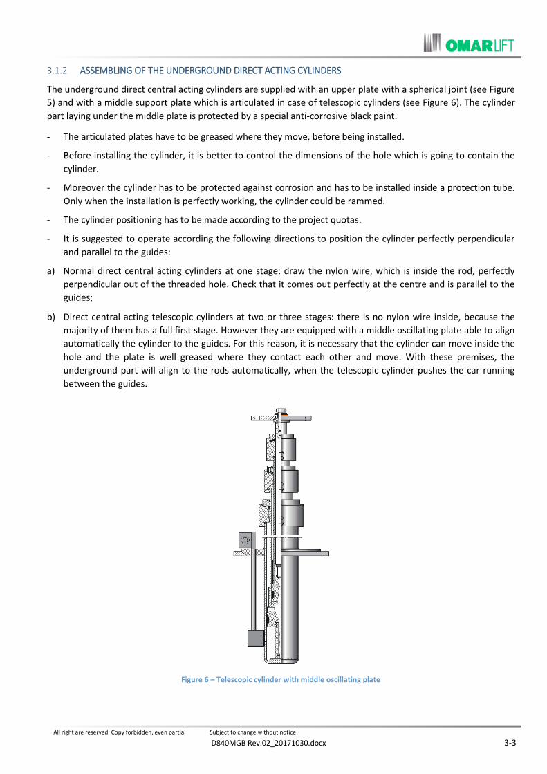
The underground direct central acting cylinders are supplied with an upper plate with a spherical joint (see Figure
5) and with a middle support plate which is articulated in case of telescopic cylinders (see Figure 6). The cylinder
part laying under the middle plate is protected by a special anti-corrosive black paint.
- The articulated plates have to be greased where they move, before being installed.
- Before installing the cylinder, it is better to control the dimensions of the hole which is going to contain the
cylinder.
- Moreover the cylinder has to be protected against corrosion and has to be installed inside a protection tube.
Only when the installation is perfectly working, the cylinder could be rammed.
- The cylinder positioning has to be made according to the project quotas.
- It is suggested to operate according the following directions to position the cylinder perfectly perpendicular
and parallel to the guides:
a) Normal direct central acting cylinders at one stage: draw the nylon wire, which is inside the rod, perfectly
perpendicular out of the threaded hole. Check that it comes out perfectly at the centre and is parallel to the
guides;
b) Direct central acting telescopic cylinders at two or three stages: there is no nylon wire inside, because the
majority of them has a full first stage. However they are equipped with a middle oscillating plate able to align
automatically the cylinder to the guides. For this reason, it is necessary that the cylinder can move inside the
hole and the plate is well greased where they contact each other and move. With these premises, the
underground part will align to the rods automatically, when the telescopic cylinder pushes the car running
between the guides.
Figure 6 – Telescopic cylinder with middle oscillating plate

All right are reserved. Copy forbidden, even partial Subject to change without notice!
3-4 D840MGB Rev.02_20171030.docx
GUIDE ARMS FOR TELESCOPIC CYLINDERS 3.1.3
Because of safety reasons in case of buckling strength, it is possible that the telescopic cylinders have no guide
arms, have guide arms only on the head of the second stage or guide arms both on the head of the second stage
and of the third stage. When the installation characteristics, require guides arm, the telescopic cylinder is
supplied with the respective fastening plates, as shown by Figure 7 - for dimensions see the technical catalogue.
The guide arms are at the customer’s care, but when requested, for safety reasons they have to be assembled
according to the distances as per EN81.2 - 12.2.5.2 and EN81-20 - 5.2.5.8.2: “In case of the group cylinder-rod
located under the car of the direct acting installation, the free distance between the lower and the upper guide
arms and the lower part of the car has to be 0.3 m at least, when the car lays on its totally compressed dampers”.
In case the established distance of 0.3 m can not be obtained with straight horizontal guide arms, they can be
properly shaped.
Figure 7 – Telescopic cylinder with fastening plates for guide arms.
CYLINDERS IN TWO OR MORE PIECES 3.1.4
The cylinder serial number is indicated by a label on the cylinder head, on the same side where is fixed the
rupture valve. The cylinders have also some indications to facilitate their assembly. Pins ensure the correct
assembly of the square flanges and if necessary, for cylinders in more parts, to be sure of the correct coupling,
there are also stamped some numbers that must coincide on the two parts after the assembly.
- Cylinders in two or three pieces have a rod with a threaded joint, while the cylinder has a joint with a squared
flange.
- The upper half of the cylinder in two pieces has a rod which is longer than the cylinder, so it is possible to fix
the screwer to the rod without disassembling the cylinder.
- The two joints of the cylinder in two pieces are hermetically closed by two metal hoods which acts as a
protection and packaging during the transport.
Special screwers (see Figure 8) or other tools, insulated with rubber, have to be fixed to the lower part of the rod, laying horizontally, before putting it in a vertical position.
It is necessary, after having removed the protection hoods, to put some rubber stripes between the rod and the cylinder, in order to avoid damages to the rod. These stripes have to be fixed well to the screws of the flanges and have to be removed just before closing the square flanges of the cylinder.

All right are reserved. Copy forbidden, even partial Subject to change without notice!
D840MGB Rev.02_20171030.docx 3-5
- Follow the next operating instructions for the assembling of the two pieces (see Figure 8 and Figure 9):
Put the lower part of the cylinder in a perfect vertical position and fix it, after having blocked the rod with a
screwer.
Block the rod of upper half with a screwer or with another tool insulated with rubber, without making it come
out of the head which contains the seals.
The block stirrup of the rod has to be removed only when the operation has finished. Danger of falling!
Lift the upper half of the cylinder with an hoist, fastening it at the two holed plates which are perfectly
welded on the head. Perfectly align the upper half with the lower half .
Remove grease and clean the male and female threads, avoiding that the solvent contacts the OR of the joint.
Control carefully that there are no bruises neither on the threads nor on the joint. If necessary, get rid of them.
Control that the OR of the joint is not damaged and is well greased.
Lower the upper half of the cylinder and slowly approach the threads without harsh movements. Control the alignment and completely screw without using the thread-locking liquid.
If there are any difficulties with screwing, unscrew immediately, control the threads and try again.
After having completely screwed the two halves, unscrew by 4/5 turns, apply the thread-locking liquid on the
screw (not on the OR), quickly screw again, checking that the red paint signs are aligned (max tolerance 4/5
mm).
Remove the screwers and control by hand that the joint of the rod is perfect all round, without bruises and steps. If necessary, smooth with fine abrasive paper (grain 400-600).
Figure 8 – Cylinder in two pieces with screws
Figure 9 – Rod and cylinder – cylinder in two pieces
Control the OR in the lower flange is perfect and lays in its seat. Clean the two flanges.

All right are reserved. Copy forbidden, even partial Subject to change without notice!
3-6 D840MGB Rev.02_20171030.docx
Pull the two square flanges closer, paying attention to match the pin and the hole (if present, join on the
same side the numberprinted on the flanges). Then screw the four screws that block the flanges, tightening
crosswise.
- In case of three pieces cylinders, we advise to proceed as follows:
In the first step, assembly the cylinder lower party (1) with the intermediate one (2), considering these two
parts as being one cylinder in two pieces ad following the indications mentioned in the previous points. To
facilitate this operation, the intermediate part jacket can be completely unthreaded and put back after having
assembled the first two parts.
In the second step, assembly the upper part (3) with the two ones previously connected (1) + (2). Even in this
phase, we can proceed like for the two pieces cylinder assembling and follow the same indications mentioned
above.
CONTROL OF THE NEW CYLINDER 3.1.5
After having installed the hydraulic part, make the following checks before starting up the first travels:
Before putting the cylinder into action, control that on its head, close to the wiper, there are no any debris, concrete, metal particles or welding cinders which could scrape the rod during its first travel.
After the first up travel, immediately control the whole surface of the rod to verify its state of preservation. In particular, if the cylinder is long, control the central part of the rod whose rectified surface could have been bruised by the vibrations during the transport. It would be necessary to smooth patiently with fine abrasive paper to avoid the precocious damaging of the seals.
PUMP UNIT 3.2
The serial number of the pump unit is reported on the plate on the tank cover.
- All the pump units and the shut-off valves are tested and adjusted before the delivery.
For this reason they can work immediately, without any further adjusting.
When the installation has been finished, the oil filled and the air purged, it will be possible to readjust the low
speed and the deceleration to optimise the installation working (see instructions in paragraph 8.2)
The pump unit room has to be located as close as possible to the lift shaft, has to be big enough, with an almost constant temperature, possibly heated in winter and ventilated in summer. If distances are bigger than 8/10 meters, please consider the pressure loss along the main pipe.
Avoid noise transmission by using anti-vibration pads under the tank and a flexible hose for the connection of the pump unit to the cylinder.
- The tank is equipped with handholds to be displaced manually and to be lifted with an hoist (see Figure 2).
The handles are engineered for the handling of the pump unit in empty conditions! (without oil).
PIPE AND HYDRAULIC CONNECTIONS 3.3
Use cold drawn steel tubes, normalised and bonderised, special for hydraulic circuits, flexible hoses which are
tested and certified for high pressure or mixed connections to connect the pump unit to the cylinder
The shut-off valve can be turned to be better aligned with the pipe direction.
The main oil pipe as to be as short as possible and avoid narrow bending.

All right are reserved. Copy forbidden, even partial Subject to change without notice!
D840MGB Rev.02_20171030.docx 3-7
When a rigid pipe is used, please note that:
Figure 10 – “WALFORM” fitting
The pipe cut has to be perfectly at 90°;
Possible bends have to be made when cold, using a proper pipe bending;
The use of a flame can cause cinders inside the pipe;
Cinders and dirt caused by the cut have to be completely eliminated;
When connecting two pipes to a cutting ring, make sure that the two pipes are perfectly aligned and that the
cutting part of the ring is turned towards the end of the pipe. Before tightening the nut of the fitting, oil both
the thread and the ring. Therefore screw with power and unscrew to control that the cutting ring has
engraved. Finally, screw again definitely the nut of the fitting, tightening it well.
WARNING: Non-normalised pipes are too hard and they can get out of the fitting!
WARNING: some countries do not allow the use of a joint with a cutting ring. In these cases, it is necessary to use a type of fitting called “WALFORM” for the connection (see Figure 10) or fittings to be welded.
When a flexible hose is used, please not that:
The flexible hose has not to be subject to tension, torsion and the bends have to be as wide as possible;
The minimum bending radius given by the manufactures has to be respected. It is reported in the following
table :
FLEX. HOSE TYPE MIN. BENDING RADIUS
¾” DN 20 240 mm
1 ¼” DN 32 420 mm
1 ½” DN 40 500 mm
2 DN 50 660 mm
- The pump units with a capacity from 360 to 600 l/min have a 2” outlet. These pump units can feed a single
cylinder with a rupture valve 2” or two cylinders together.
- In case of a single cylinder, the connection between the pump unit and the rupture valve can be made:
With a single flexible hose 2” and nipples 2”, 60° angle (see Figure 11);
With two parallel steel pipes, diameter 42 mm and two three – way fittings 1” fi x 2” x fi (see Figure 12).

All right are reserved. Copy forbidden, even partial Subject to change without notice!
3-8 D840MGB Rev.02_20171030.docx
Figure 11 – Connection with flex hose 2”
Figure 12 – Connection with two rigid pipes Ø 42
CONNECTION OF INSTALLATIONS WITH TWO CYLINDERS 3.4
In case of installations with two cylinders, the pipes which feed the two cylinders have to have the same diameter, the same length, and follow ways as symmetrical as possible (see Figure 13).
The rupture valves of the two cylinders have to be hydraulically connected allowing the piloting pressure balance. The rupture valves are equipped with a 1/8” threaded hole. The connection has to be done with 1/8” fittings and steel pipes with a 6 mm diameter, 1 mm thick. See also the “Operating Instructions for Omar Lift rupture valve”.
Figure 13 – Installation with two cylinders

All right are reserved. Copy forbidden, even partial Subject to change without notice!
D840MGB Rev.02_20171030.docx 4-1
ELECTRICAL CONNECTIONS 4
GENERAL REGULATIONS 4.1
Any electrical connection has to be carried out by trained and qualified staff, according to the specific regulations.
Before starting any kind of work, always disconnect the electrical power opening the general switch.
The cables for the electrical power feeding have to have a section sufficient for the requested power. Their isolation has to be suitable according to the voltage of the electrical network. The connection cables have not to be put in contact with parts subject to strong heating.
The grounding cable has to be always connected to the bolt marked with the proper symbol.
CONNECTION BOX 4.2
The connection box is on the pump unit cover, near the valve box.
The box of the standard pump unit includes (see Figure 14):
a) Terminal block of the electrical motor
b) Grounding bolt
c) Thermostat for oil temperature 70°C
d) Motor thermistors 110°C
e) Valve heating resistor 60 W (optional).
Figure 14 – Connection box for standard pump unit
Figure 15 – Connection box for wired pump unit
The images shown are indicative only
The pump unit box, cabled (optional), includes (see Figure 15):
a) Terminal block of the electrical motor
b) Grounding bolt
c) Terminals of the thermostat for the oil cooling (optional)
d) Terminals of the max pressure switch (optional)
e) Terminals of the min. pressure switch (optional)
f) Terminals of coil EVD
g) Terminals of coil EVR
h) Terminals of coil EVS (optional)
i) Terminals of coil EVE
j) Terminals of motor thermistors 110°C
k) Terminals of oil thermostat 70°C
l) Terminals of the valve heating resistor (optional)
m) Terminals of the overload pressure switch (optional)
n) Terminals EVD-HDU (if installed)

All right are reserved. Copy forbidden, even partial Subject to change without notice!
4-2 D840MGB Rev.02_20171030.docx
ELECTRICAL CONNECTION OF THE THREE-PHASE MOTOR 4.3
The terminals of the motor are already fixed to the terminal block inside the connection box.
In case of a direct start of the motor (or with soft starter), frequency and one tension of the motor have to
correspond to the frequency and tension of the electrical power network.
The connection bands on the terminal block have to respect the diagram appearing on the motor plate or the directions of the table (see Figure 16).
In case of a soft starter start, follow the directions of the manufacturer.
In case of a star-delta start, the lower tension of the motor has to be equal to the network tension. Frequency
has to be equal to the network frequency (i.e.: Network 400V – 50Hz, motor 400/690V – 50Hz).
In case of a star-delta start, the connection bands in the terminal block have to be eliminated.
DISPOSITION OF TERMINAL CONNECTION BANDS FOR THREE-PHASE MOTORS
DIRECT START
Power 230 V – Motor 230 / 400
Power 400 V – Motor 400 / 690
Power 415 V – Motor 415 / 720
Power 400 V – Motor 230 / 400
Power 690 V – Motor 400 / 690
Power 720 V – Motor 415 / 720
– Δ START
Remove the terminal connection bands
The connection sequence is carried out in the panel.
Power 230 V – Motor 230 / 400
Power 400 V – Motor 400 / 690
Power 415 V – Motor 415 / 720
Figure 16 – Electrical connection of three-phase motors
ELECTRICAL CONNECTION OF THE SINGLE PHASE MOTOR 4.4
The single phase motor is equipped with its proper condenser supplied by the manufacturer. Follow the diagram
of the motor manufacturer or the diagram shown by Figure 17 to obtain a correct connection.

All right are reserved. Copy forbidden, even partial Subject to change without notice!
D840MGB Rev.02_20171030.docx 4-3
Figure 17 – Electrical connection of single phase motor
MOTOR PROTECTION WITH THERMISTORS 4.5
The motors, which work covered with oil, are supplied with their thermistors 110°C. The thermistors are inserted
in windings, one for each phase and they are connected in series. Their resistance remains very low, under 110°C.
but increases drastically when 110çC are reached in one or in all windings.
For the motor protection, the thermistors have to be connected to a proper release electronic relay susceptible to the resistance variation.
WARNING: the thermistors have not to be submitted to tensions higher than 2,5 Volt.
When the thermistors are properly connected, they protect the motor against the overheating of the windings.
Overheating could be caused by:
- Lack of a phase in the feeding
- Too frequent activation
- Excessive tension variations
- Excessive oil temperature
ELECTRICAL CONNECTION OF THE VALVE GROUP 4.6
Valve NL (see Figure 18) can be equipped with the following electro-valves:
EVD = Down travel electro-valve (both normal and emergency)
EVR = Deceleration electro-valve (high speed)
EVS = Up travel electro-valve (star-delta or soft starter).
The scheme for the electrical wiring is shown in the following figures:

All right are reserved. Copy forbidden, even partial Subject to change without notice!
4-4 D840MGB Rev.02_20171030.docx
Figure 18 – “NL” valve
The electro-valves have the following functions:
ELECTRO-VALVE EVD with double coil: it controls the down travel both in a normal and in an emergency
condition, with battery 12 V c.c. When it is fed it allows the down travel with a low speed. This electro-valve
has to be fed only during the whole down travel. Together with EVR, it allows the high speed.
ELECTRO-VALVE EVR with a single coil: it controls the high speed and the deceleration. This valve has to be
fed both during the down and the up travels to reach the high speed; it has to be disconnected before
reaching the floor to obtain the deceleration and the low speed. For a good deceleration, the EVR coil has to
be disconnected according to the installation speed: the bigger the installation speed is, the bigger the
distance from the landing floor has to be.
The following examples show the disconnection distance of the electro-valve EVR from the floor:
ELETTROVALVOLA EVS with a single coil: it is used for installations with – Δ START or SOFT STARTER
(supplied on demand). This electro-valve controls the oil pressure. When the EVS coil is disconnected, the oil
returns to the tank without pressure, through the VM valve; the motor is activated and reaches its rate
without load. Only when the motor has reached its rate (Δ phase in case of – Δ starts, or when the start
phase has finished, in case of a soft starter), by feeding the EVS coil, pressure will begin to rise and keep the
requested installation value until EVS is not disconnected.
During the up travel, the EVS coil has to be kept connected for a moment after the stop. In this way a soft stop without bumps is obtained. This can be reached by connecting in parallel a 1000 – 1500 μF condenser – properly supplied by OmarLift – to the coil or by connecting other systems directly to the electrical panel. The connection of the condenser to the coil, has to be carried out only when it is not possible to obtain the wished delay through the electrical panel. For the connection follow the scheme reported below.
CAR SPEED EVR DISCONNECTION
RAISED DISTANCE DESCENT DISTANCE
0,40 m/s 0,50 m 0,60 m
0,60 m/s 0,70 m 0,80 m
0,80 m/s 0,90 m 1,00 m
All right are reserved. Copy forbidden, even partial Subject to change without notice!
D840MGB Rev.02_20171030.docx 4-5
Figure 19 – Connection scheme valves
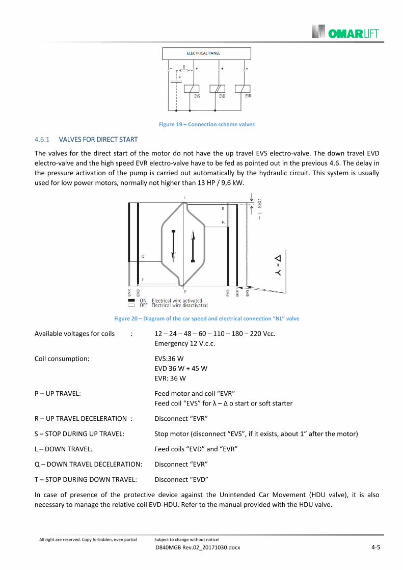
VALVES FOR DIRECT START 4.6.1
The valves for the direct start of the motor do not have the up travel EVS electro-valve. The down travel EVD
electro-valve and the high speed EVR electro-valve have to be fed as pointed out in the previous 4.6. The delay in
the pressure activation of the pump is carried out automatically by the hydraulic circuit. This system is usually
used for low power motors, normally not higher than 13 HP / 9,6 kW.
Figure 20 – Diagram of the car speed and electrical connection “NL” valve
Available voltages for coils : 12 – 24 – 48 – 60 – 110 – 180 – 220 Vcc.
Emergency 12 V.c.c.
Coil consumption: EVS:36 W
EVD 36 W + 45 W
EVR: 36 W
P – UP TRAVEL: Feed motor and coil “EVR”
Feed coil “EVS” for λ – Δ o start or soft starter
R – UP TRAVEL DECELERATION : Disconnect “EVR”
S – STOP DURING UP TRAVEL: Stop motor (disconnect “EVS”, if it exists, about 1” after the motor)
L – DOWN TRAVEL. Feed coils “EVD” and “EVR”
Q – DOWN TRAVEL DECELERATION: Disconnect “EVR”
T – STOP DURING DOWN TRAVEL: Disconnect “EVD”
In case of presence of the protective device against the Unintended Car Movement (HDU valve), it is also
necessary to manage the relative coil EVD-HDU. Refer to the manual provided with the HDU valve.


All right are reserved. Copy forbidden, even partial Subject to change without notice!
D840MGB Rev.02_20171030.docx 5-1
OIL FOR LIFTS – CIRCUIT FILLING AND AIR PURGING 5
CHARACTERISTICS AND CHOICE OF THE OIL 5.1
The hydraulic oil is a very important part of the hydraulic installation.
In particular, in case of installations having medium or high traffic, “THE CHOICE OF GOOD QUALITY OIL
INCREASES THE TEMPERATURE RANGE WITHIN WHICH THE LIFT WORKS IN A COMFORTABLE WAY AND
INCREASES THE DURATION OF ITS HYDRAULIC COMPONENTS”.
A good quality oil for lifts has to have the following main characteristics:
1) Viscosity at 40°C:
46 cSt, oil suitable for low temperatures, in particular for the first starts in the morning.
68 cSt, oil suitable for high temperatures, in particular caused by high traffic.
2) Viscosity index:
Low (150), oil suitable for low and medium traffic.
High (180), oil suitable for medium/high and high traffic.
3) Flash point: > 190°C
4) Pour point: < -30°C
5) Specific weight at 15°C: 0,88 kg/ dmΔ
6) Air release a 50°C: < 10 min
For a quick separation of the air and the elimination of the oil foam.
7) Further characteristics:
- Anti-oxidant: it prevents the creating of dirt and dregs.
- Anti-corrosion: it doesn’t corrode metals, copper, seals etc.
- Anti-wear: it assures the duration of the moving parts.
- Anti-rust: it protects and conserves the metallic components.
- Anti-emulsion: it makes the spontaneous separation of water from oil easy.
The oil has to be chosen focusing on the installation characteristics (temperature and ventilation of the machine room, installation traffic) as well as on the temperature-viscosity characteristics of the oil.
In particular, note that:
- The number which follows the type or the name of the oil shows only the oil viscosity when its temperature is
40°C (32/46/68 cSt ecc.).
- The viscosity index shows the oil stability when the temperature changes. The oil viscosity increases when the
oil cools and decreases when the oil heats. These variations are important if the viscosity index is low,
consequently “IT IS RECOMMANDED TO USE OIL WITH A HIGH VISCOSITY INDEX; 150/180/190 according to
the situations.
Oils with a low viscosity index, such as 98/110/120, have to be used in installations with an almost constant
room temperature and a number of travel per hour not higher than 8/10. The installation works well if the
viscosity variation is between 250 and 40 cSt about. This can be obtained with an oil having a high viscosity
index, when the temperatures go from 8/15 to 50/60°C.

All right are reserved. Copy forbidden, even partial Subject to change without notice!
5-2 D840MGB Rev.02_20171030.docx
Oil can be heated or cooled with proper resistors or heat exchangers to keep the temperature back within the
right levels or optimise the installation working.
Oil has to be heated when the machine room temperature reaches low values which could jeopardise the installation working during the first travels in the morning. The car has to be drawn back to the lowest floor automatically, not later than 15 minutes after the last travel. In this way all the oil in the tank can be heated. An electrical resistor (500 W) with thermostat is normally used to heat the oil in the tank.
- When the oil temperature does not reach low values, a small resistor (60 W) can be used to heat the
valve group only.
Oil has to be cooled when the high number of travels makes the temperature increase, exceeding the acceptable temperature for the used oil, or reaching the max. temperature of 70, making the safety thermostat intervening.
Oil heats not only because of the high traffic, but also because the machine room is small, not ventilated, is placed under the roof or the oil in the tank reaches the minimum indispensable quantity. For the oil cooling, systems with air or with water can be used.
- The list which follows shows examples of some types of oil which, thanks to their characteristics, are suitable
for the lift field.
The oil shown are not the only ones which can be used. No preference or qualification has been given to the
order of the list:
PRODUCT BRAND
WORKING CONDITION
LOW-MEDIUM
WORKING CONDITION
MEDIUM/HIGH-HIGH
Type Viscosity index Type Viscosity index
AGIP H LIFT – 46/68 150 ARNICA 46/68 164
API APILUBE HS 68 150
CASTROL HYSPIN M 46 160 HYSPIN AW M68 190
ESSO INVAROL EP 46 160 INVAROL EP 68 180
FINA HYDRAN HV 68 151
I.P. HYDRUS HI 46 HYDRUS HX 68 175
OLEOTECNICA MOVO M 46/68 154 MOVO HVI 46/68 182
ROLOIL LI/46 – HIV 160 LI/68 – HIV 175
SHELL TELLUS T 46 153 TELLUS T 68 193
SHELL ELEVOIL 68 183
TOTAL EQUIVIS HZS 46 160 EQUIVIS HZS 68
No responsibility is taken for differences or variations of types and characteristics made by the oil manufactures.

All right are reserved. Copy forbidden, even partial Subject to change without notice!
D840MGB Rev.02_20171030.docx 5-3
CIRCUIT FILLING AND AIR PURGING 5.2
When an installation is new, the tank, the cylinder, the connection pipes, the valve and the silencer have no oil
inside. Consequently, it is necessary to fill very well all the components of the hydraulic circuit and purge air out
of them completely.
The quantity of oil to be put in the installation has to be the max allowed, in order to have a very silent installation, without foam in the oil, and very low overheating.
OIL QUANTITY = A + B x TRAVEL (m) + C x LENGTH (m)
1. OIL FOR TANK = “A” CAPACITY
TANK TYPE 110/S 135/S 210/S 320/S 450 680
CAPACITY “A” - LITRES 100 125 190 305 430 650
2. OIL FOR THE CYLINDER (FOR THE FILLING UP WITHOUT TRAVEL) = “B
ROD DIAMETER MM 50 60 70 80 85 90 100 110 120 130 150 180 200 230
OIL “B” l/m 3,1 4,5 5 3,8 3,2 5,7 5,6 6,4 6,1 8,5 8,3 15,6 18,9 19,4
NOTE: see paragraph 11.3 for oil for telescopic cylinders.
3. OIL FOR CONNECTION PIPES= “C”
PIPES Ø 22 x 1,5
Flex ¾” Ø 35 x 2,5 Flex 1 ¼”
Ø 42 x 3 Flex 1 ½”
N° 2 pipes Ø 42 x 3
Flex 2”
OIL “C” l/m 0,30 0,70 1,00 2,00 1,90
The oil filling has to be done pouring the oil from the side of the moving half-cover, bringing the level at 8/10 cm
about from the upper edge.
Before pouring the oil into the tank, make sure that there is no dirt or water inside.
The air has to be purged from the highest point of the circuit which normally is the cylinder head. The oil has to enter the circuit very slowly, without creating turbulence and mixing with air which needs time to get out.
Operate as follows to get rid of the air completely (see Figure 21).
1) Unscrew completely and remove the purge screw on the head of the cylinder (or cylinders).
2) If the rupture valve is not adjusted (red label on it), its regulation screw has to be unscrewed.
3) Disconnect electrically the coil of the electro-valve EVR of the high speed. Only in this way a small quantity of
oil gets into the cylinder without turbulence.
4) Activate the motor for an up travel ( – Δ too, if it exists) for some seconds and check if the pump turns in the
right direction. If it turns in the wrong way, a strong and bothering noise will be heard. The two phases in the
motor feeding need to be exchanged.
5) Keep the motor activated for 10-15 seconds and stop it for 20-30 seconds to allow the air go out. Repeat this
operation several times, until only oil, without air, comes out from the purge screw.

All right are reserved. Copy forbidden, even partial Subject to change without notice!
5-4 D840MGB Rev.02_20171030.docx
6) Close the purge screw of the cylinder and adjust the rupture valve, in case it has not been adjusted previously
in the factory. If the rupture valve needs to be adjusted, carefully follow the operating instructions enclosed
to it, or the directions in chapter “ADJUSTING AND TEST OF THE RUPTURE VALVE”.
7) In case the pump unit is located higher than the cylinder head, purge the air also from the proper screw on
the shut-off valve.
8) Reset the oil level in the tank, if necessary and make an upward travel at low speed, checking that all the
parts of the installation are in order and that the oil quantity is sufficient.
The motor has always to be covered by oil even when the cylinder is at the upper end.
Avoid that the oil level decreases until it uncovers the motor-pump group. In this case in fact the pump could suck air, making all the above purging operations void.
9) Connect again the coil of the electro-valve EVR to obtain the high speed and check the other functions:
acceleration, deceleration, upward start, downward start, etc.
10) Check that in the circuit there is no remaining air. At this purpose, stop the car on an intermediary floor, close
the shut-off valve and turn off the power, get into the car and check that there is no strong lowering, get off
the car and verify that the car does not go quickly back to its initial position.
Figure 21 – Air purging from the circuit
All right are reserved. Copy forbidden, even partial Subject to change without notice!
D840MGB Rev.02_20171030.docx 5-5
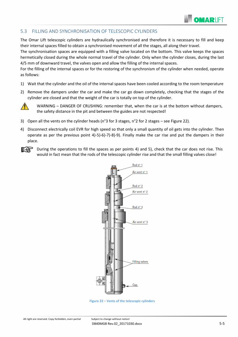
FILLING AND SYNCHRONISATION OF TELESCOPIC CYLINDERS 5.3
The Omar Lift telescopic cylinders are hydraulically synchronised and therefore it is necessary to fill and keep
their internal spaces filled to obtain a synchronised movement of all the stages, all along their travel.
The synchronisation spaces are equipped with a filling valve located on the bottom. This valve keeps the spaces
hermetically closed during the whole normal travel of the cylinder. Only when the cylinder closes, during the last
4/5 mm of downward travel, the valves open and allow the filling of the internal spaces.
For the filling of the internal spaces or for the restoring of the synchronism of the cylinder when needed, operate
as follows:
1) Wait that the cylinder and the oil of the internal spaces have been cooled according to the room temperature
2) Remove the dampers under the car and make the car go down completely, checking that the stages of the
cylinder are closed and that the weight of the car is totally on top of the cylinder.
WARNING – DANGER OF CRUSHING: remember that, when the car is at the bottom without dampers, the safety distance in the pit and between the guides are not respected!
3) Open all the vents on the cylinder heads (n°3 for 3 stages, n°2 for 2 stages – see Figure 22).
4) Disconnect electrically coil EVR for high speed so that only a small quantity of oil gets into the cylinder. Then
operate as per the previous point 4)-5)-6)-7)-8)-9). Finally make the car rise and put the dampers in their
place.
During the operations to fill the spaces as per points 4) and 5), check that the car does not rise. This would in fact mean that the rods of the telescopic cylinder rise and that the small filling valves close!
Figure 22 – Vents of the telescopic cylinders

All right are reserved. Copy forbidden, even partial Subject to change without notice!
D840MGB Rev.02_20171030.docx 6-1
CONTROL AND TESTS 6
After the assembling operations have been completed, after the oil has been filed and the air has been purged
from the circuit, it is proper to make the following checks.
CHECK OF THE OIL LEVEL IN THE TANK 6.1
When the cylinder is in upper end position, check that the oil level in the tank covers the motor-pump group
well (min. 2 cm over the motor).
When the cylinder is in lower extra-travel position, the oil level has to be 7/8 cm under the tank edge.
CHECK OF THE MAX. PRESSURE 6.2
When the main line shut-off valve is closed, the motor activated for the upper travel, the oil discharges into
the tank and the manometer shows the max. adjusting pressure of the overpressure valve.
The value of the max adjusting pressure has to correspond to 1,4 times the max static pressure with full load.
CHECK OF THE START IN UPWARD DIRECTION 6.3
In order to get a smooth start of the motor in upward direction without load, be sure that:
In installations with direct start, coil EVR has not to be connected before the motor;
In installations with star-delta start of soft-starter, coils EVS and EVD have to be connected after that the
manoeuvre panel has completed the electrical motor start;
When the shut-off valve is closed, discharge pressure using the emergency button and start up the motor
again: check that the pressure rises slowly from its minimum to its maximum value. If necessary, operate as
per chapter “ADJUSTING AND REGULATION OF “NL” VALVE GROUP”.
CHECK OF THE SEALING OF SEALS AND PIPES 6.4
Check visually the connection pipe sealing, in particular the joints of the flexible hoses and rigid pipes.
Check that no dirt is present in the oil recovering pipe and that the pipe is connected to its proper tank.
After some travels, the rod looks covered by a small quantity of oil needed for its lubrication.
A possible oil ring on the rod could appear I the first working days because of deformation of hardening of the
seal, in particular if the cylinder has remained laid down for a long time on the site.
This phenomenon will disappear after a short period of time. Only if there is a huge oil quantity in the recovery
tank, it will be necessary to replace the seals.
CHECK OF THE RUPTURE VALVE INTERVENTION 6.5
Be sure that the rupture valve has already been adjusted.
If necessary, regulate it according to the handbook for the adjusting operations or the instruction reported in
paragraph 7.2 “ADJUSTING OF THE RUPTURE VALVE”.
The down travel intervention test has to be carried out when the car has been loaded with the nominal load
uniformly distributed according to the instructions reported in paragraph 7.3 “TEST AND WORKING OF THE
RUPTURE VALVE”.
CHECK OF THE INSTALLATION AT TWICE THE STATIC PRESSURE 6.6
This check has to be carried out only after the check of the rupture valve intervention and when the oil
temperature is constant.

All right are reserved. Copy forbidden, even partial Subject to change without notice!
6-2 D840MGB Rev.02_20171030.docx
The oil has not to be hot: the test has to be carried out only when the oil temperature is the same as the room
temperature (please note that in a close circuit, the temperature variation of 1°C can cause a pressure variation
of 9 bar):
- If necessary, determine the max. static pressure loading the car with the nominal load.
- Take the piston to upper end position with the main motor until the adjusting pressure is reached and stop in
this position.
- Increase the pressure slowly with the hand pump until double the max. static pressure.
Check pressure fall and losses within 5 minutes, taking into account the possible effects due to the oil
temperature variation If necessary, repeat the test, re-charging the pressure for 2/3 times with the hand pump,
controlling that pressure does not decrease by 5/6 bar during the first 4/5 minutes. If needed, read the paragraph
MAINTENANCE OF THE HYDRAULIC INSTALLATION”.
- When the test has finished, take back the pressure to the value of the static pressure, activating the
emergency button manually and control visually the integrity of the hydraulic system.
CHECK OF THE ROD COUNTER-PRESSURE AND HAND MANOEUVRE 6.7
- For indirect acting installations 2:1, check that, when the car is blocked on the proper parachutes or lays on
its dampers, by activating the red emergency button, the rod does not go down making the ropes loosen. If
necessary, screw the screw n. 3 until it stops.
- For any kind of installation, check that, when the car is free to go down, it goes down regularly at a reduced
speed when the emergency button is pushed.
The emergency valve is protected against casual activation (EN81-2 – 12.9.1.4 and EN81-20 – 5.6.3.7) by a spring which requires to apply an adequate force.
CHECK AND ADJUSTING OF THE HAND PUMP 6.8
When the main shut-off valve is closed, activating the hand pump, the pressure on the manometer has to
increase up to the adjusting value. The safety valve of the hand pump has to be adjusted at 2,3 times the static
pressure of the installation with full load.
The regulation screw of the hand pump is on the left of the lever. If necessary, see instructions at point 8.2.8 for
the regulation.
CHECK OF THE TIME DURING WHICH THE MOTOR IS UNDER TENSION 6.9
Simulating the installation working during the up travel, control the regulation of the intervention time of the
timer which keeps the motor under tension.
CHECK OF THE MOTOR AND THERMISTOR PROTECTION 6.10
All the motors are supplied with thermistors with intervention temperature corresponding to 110°C.
The resistance of the thermistors is about 200-300 Ohm when their temperature is lower than 110°C, but it
increases strongly to 1500/3000 Ohm when their temperature is reaching 110°C. If the electrical panel is
equipped with the special release device for the thermistors and they are correctly connected, it is possible to
check the working, simulating, for example, the lack of a phase in the motor feeding or following the instructions
given by the manufacturer of the electrical panel. The approx.. values for the intervention times of the
thermistors are the following ones:

All right are reserved. Copy forbidden, even partial Subject to change without notice!
D840MGB Rev.02_20171030.docx 6-3
TEMPERATURES TIMES
from 20 to 110°C 15-20 s
from 50 to 110°C 10-15 s
NOISE 6.11
The noise of Omar Lift pump units is normally very low. With average working conditions, when oil temperature is
at 30/40° and pressure at 25/30 bar, noise does not normally exceed the following values.
PUMP UNIT TYPE 50 Hz 60 Hz
Up to 150 l/min : 57 ÷ 59 dB(A) 62 dB(A)
From 180 to 300 l/min : 59 ÷ 61 dB(A) 64 dB(A)
From 360 to 600 l/min : 60 ÷ 64 dB(A) 67 dB(A)
HOMELIFT (external motor) 62 dB(A) 65 dB(A)
Anyway some external causes can determine an increase in the noise transmission of the installation: in fact the
noise is sometimes transmitted or even expanded by the building walls or by the connecting pipes, thus reaching
the lift space or the rooms next to it. When it happens it is necessary to operate as follows:
1. Use some thick rubber to isolate the connecting pipes from collars used to fix the pipes to the walls;
2. Use some thick rubber to isolate both the cylinder head from its fixing collar and the cylinder bottom from its
support;
3. To connect the pump unit to the cylinder use a piece of flexible hose placed near the pump unit which has to
be at least 5/6 metres long;
4. Add some oil in the tank up to the maximum level allowed;
5. Make sure that the pipe discharging oil from the valve to the tank, always discharges under the tank oil level;
6. Check that there is no air in the oil.
MANOMETER SHUT-OFF 6.12
ATTENTION! The mentioned currents are indicative only. For other motor dimensions please consider a proportional current. In every case refer to the motor dataplate.
The manometer, which is placed on the valve group, is supplied with an exclusion shut-off. During the regular working of the lift, the manometer shut-off has to be perfectly closed to avoid possible oil losses or damage to the manometer itself


All right are reserved. Copy forbidden, even partial Subject to change without notice!
D840MGB Rev.02_20171030.docx 7-1
ADJUSTING AND TEST OF THE RUPTURE VALVE 7
GENERAL INFORMATION 7.1
- The rupture valve is the hydraulic parachute assembled on the cylinder. It operates against the free fall or the
down travel with an excessive speed.
- The rupture valve has to be capable to stop the car during the down travel and keep it still, when the
downward speed exceeds the nominal speed + 0,3 m/s at the latest.
- Practically it is possible to fix a speed increase corresponding to 30% of the nominal speed. This value covers
all the applications until the max admitted speed for hydraulic installations: 1 m/sec.
- The car speed changes with the variation of the oil which goes through the valve: adjusting a valve means
limiting the passage to a minimum value which lets an oil quantity, lower than the adjusting value, run free
and blocks the oil flow when the adjusting value is reached.
This is obtained by operating on the valve regulation screw:
screw, the adjusting value decreases.
Unscrew, the adjusting value increases.
- The excessive speed during the downward travel (or simulation of the rupture of the connection pipe) is
obtained by closing the screw n°4 on the pump unit valve group.
ADJUSTING OF THE RUPTURE VALVE 7.2
If the rupture valve has not been adjusted in the factory, it is necessary to adjust it directly on the installation,
using the diagrams of the Tab. 1.
There are four diagrams in this table, corresponding to the four types of valve.
- “Q” value, in litres/min. represents the oil flow through the rupture valve.
- “Y” value, represents how many mm the regulation screw has to lean out, when the regulation operation has
been completed. Operate as follows to adjust the rupture valve:
a) Find out the size of the valve to be set up, reading the valve plate or drawing it from the oil inlet dimension:
OIL INLET
END FITTING DIAMETER
[mm] VALVE SIZE
NOMINAL FLOW RANGE
l/min
R = ¾” 22 VP HC34 5 ÷ 55
R = 1 ¼” 35 VP 114 35 ÷ 150
R = 1 ½” 42 VP 112 70 ÷ 300
R = 2” 2”; 2 x 42 VP 200 150 ÷ 600
b) Find out the flow in litres/min. of the pump assembled on the pump unit, the nominal speed depends on.
c) Calculate value “Q” in litres/min. able to make the downward speed increase by 30% about with respect to
the nominal speed. Considering installations with upward speed equal to the downward speed, it results:
Installation with a rupture valve (one cylinder)
Q (l/min) = pump capacity x 1,3

All right are reserved. Copy forbidden, even partial Subject to change without notice!
7-2 D840MGB Rev.02_20171030.docx
Installation with two rupture valves (two cylinders)
Q (l/min) = pump capacity x 1,3 : 2
d) Find out “Y” value on the adjusting table. This value corresponds to the “Q” capacity which has been previously calculated and position the regulation screw at value “Y”, as the drawing shows.
Example: n°1 Valve VP 114
n° 1 Pump 100 l/min
Q = 100 x 1,3 = 130 l/min
Y = 30 mm
Figure 23 – Graph for valve adjusting
VALVE Ø R Ø B Q nominal
[l/min] Q set up Max.
[l/min]
VP HC34 R ¾” 16 5 ÷ 55 100
VP 114 R 1 ¼” 24 35 ÷ 150 300
VP 112 R 1 ½” 34 70 ÷ 300 550
VP 200 R 2” 40 150 ÷ 600 900
ΔP = 1 Bar
T = 20°C
Viscosity = 144 cSt
Tab. 1
VP HC34

All right are reserved. Copy forbidden, even partial Subject to change without notice!
D840MGB Rev.02_20171030.docx 7-3
TEST AND WORKING OF THE RUPTURE VALVE 7.3
a) Get the travel shaft free and be sure that the whole lift equipment is perfectly working.
b) Load the car with the nominal load and take it to the upper floor.
c) Screw the screw n°4 completely. This screw is located on the NL vale group on the pump unit.
d) Make a travel from the upper floor to the lowest one.
e) The car speed increases up to exceeding the nominal speed.
f) The rupture valve intervenes when the downward speed increases by 30% about with respect to the nominal
speed. As a result, the car decelerates up to stop.
g) If, after some-metre run at a speed higher than the nominal one, the rupture valve has not intervened, stop the car pushing button “STOP”. Adjust again the rupture valve, screwing the regulation screw gradually (/ turn by / turn) and repeat the test.
h) Unscrew again screw n°4 by two turns and fix it with a proper nut. Check that the valve does not intervene
during the downward travel, at these conditions.
i) When the test has finished, block the regulation screw with the lock nut and seal with red paint or link the
two proper holes, one located on the screw and the other on the valve block, with iron wire and plumb.


All right are reserved. Copy forbidden, even partial Subject to change without notice!
D840MGB Rev.02_20171030.docx 8-1
ADJUSTING AND REGULATION OF “NL” VALVE GROUP 8
GENERAL INFORMATION 8.1
The valve group is adjusted and tested in the factory together with shut-off valve and motor-pump group which is
assembled inside the pump unit. When the regulation has been completed, a diagram is prepared which
reproduces the speed behaviour during upward and downward travels and this diagram can be supplied on
request (see Figure 24). The identification plate (see Figure 25) lays on the pump unit cover and shows the valve
drawing, all the regulation points, the description of the electro-valves and the data needed to identify the
installation. In case, for different reasons, it is necessary to readjust the valve, previously check that:
- All the electrical connections have been carried out correctly.
- The oil in the tank is the advised one and its temperature is between 18 and 30°C.
Figure 24 – Upward and downward speed diagram
ADJUSTING AND REGULATION OF “NL” VALVE GROUP 8.2
The regulation operations are reported in the “REGULATION TABLE OF THE NL VALVE” (see Errore. L'origine
riferimento non è stata trovata.)
Follow the “GENERAL DRAWING” to understand better the valve working and its regulations (see Figure 26.)
Figure 25 – Identification plate
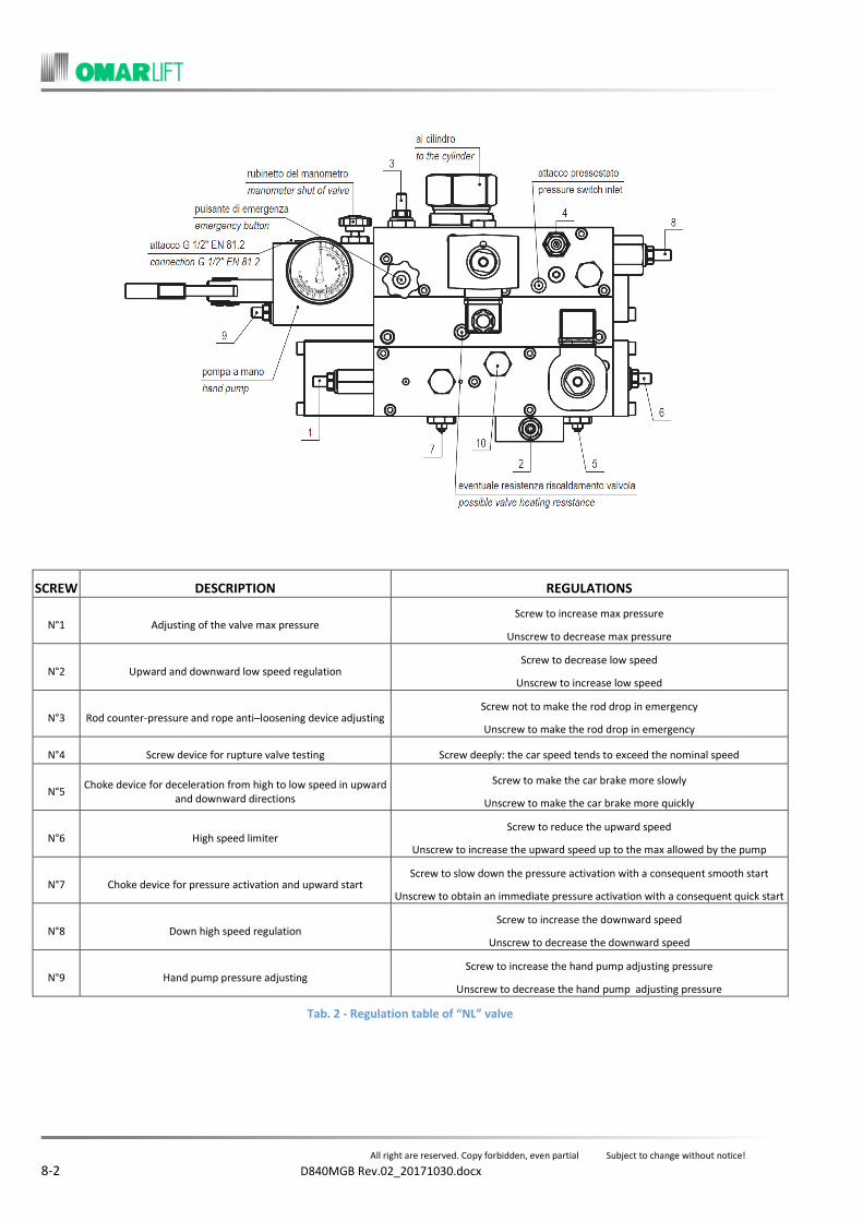
All right are reserved. Copy forbidden, even partial Subject to change without notice!
8-2 D840MGB Rev.02_20171030.docx
SCREW DESCRIPTION REGULATIONS
N°1 Adjusting of the valve max pressure Screw to increase max pressure
Unscrew to decrease max pressure
N°2 Upward and downward low speed regulation Screw to decrease low speed
Unscrew to increase low speed
N°3 Rod counter-pressure and rope anti–loosening device adjusting Screw not to make the rod drop in emergency
Unscrew to make the rod drop in emergency
N°4 Screw device for rupture valve testing Screw deeply: the car speed tends to exceed the nominal speed
N°5 Choke device for deceleration from high to low speed in upward
and downward directions
Screw to make the car brake more slowly
Unscrew to make the car brake more quickly
N°6 High speed limiter Screw to reduce the upward speed
Unscrew to increase the upward speed up to the max allowed by the pump
N°7 Choke device for pressure activation and upward start Screw to slow down the pressure activation with a consequent smooth start
Unscrew to obtain an immediate pressure activation with a consequent quick start
N°8 Down high speed regulation Screw to increase the downward speed
Unscrew to decrease the downward speed
N°9 Hand pump pressure adjusting Screw to increase the hand pump adjusting pressure
Unscrew to decrease the hand pump adjusting pressure
Tab. 2 - Regulation table of “NL” valve

All right are reserved. Copy forbidden, even partial Subject to change without notice!
D840MGB Rev.02_20171030.docx 8-3
Figure 26 – General drawing

All right are reserved. Copy forbidden, even partial Subject to change without notice!
8-4 D840MGB Rev.02_20171030.docx
ADJUSTING OF THE OVER-PRESSURE VALVE: SCREW N°1 8.2.1
The over-pressure valve has to be adjusted with a pressure 1,4 times the max. static pressure with a full load. (Higher values, corresponding max to 1,7 times, are also admitted, only if this possibility has been taken into account during the project phase).
The max pressure is reached only when the piston is in upper end position or when the main line valve is closed.
- Close the shut-off valve of the main line and open the manometer valve.
- Be sure that screw n°2 (low speed) and screw n° 7 (pressure activation) are unscrewed by 4/5 turns.
- Screw the screw n°1 and discharge the possible pressure with the red manual emergency button.
- Start the motor and connect the coil of the electro-valve EVS in installations where required.
- Screw the screw n°1 until the max wanted pressure value is reached and stop the motor.
- Discharge again pressure with the hand button, activate the motor checking that the manometer shows the
adjusted pressure, block the nut and stop the motor.
In case the given pressure needs to be decreased, discharge the pressure with the hand button, unscrew the screw n°1 and repeat the adjusting.
ADJUSTING OF THE START IN UPWARD DIRECTION: SCREW N°7 8.2.2
The start in upward direction is smooth and jump-free when the pressure value goes slowly from minimum to
maximum. Pressure increasing is regulated with the screw n°7 – Pressure activation.
- Close the main shut-off valve, stop the motor and discharge the pressure with the emergency button. In case
pressure needs to be taken to zero, unscrew the screw n°3 – Counter-pressure.
- Screw the screw n°7, completely, activate the motor and connect coil EVS, if it exists. At these conditions,
pressure will not increase or will increase later.
- With motor and EVS connected, unscrew step by step the screw n°7 until the manometer shows the pressure
increasing slowly and regularly until its max value.
- Check again the adjusting of the adjusting of the max pressure and, if necessary, take it back to the wanted
value.
- Check the pressure activation and block the nuts of screws n°1 and n°7.
REGULATION OF THE LOW SPEED: SCREW N°2 8.2.3
The low speed upward and the low speed downward are regulated with screw n°2.
- Check that the main shut-off valve is open.
- Switch off the coil of the electro-valve EVR, corresponding to the upward and downward high speed.
- Activate the motor and connect EVS, if existing. During the upward travel at a low speed, regulate screw n°2,
as wanted.
- Make a downward travel at low speed, connecting the coil of the electro-valve EVS only.
Check that, at these conditions, no vibrations appear during the downward travel. If necessary, after having regulated the max downward speed, (point 8.2.5), increase the low speed, unscrewing screw n°2 lightly and block the nut in this position.

All right are reserved. Copy forbidden, even partial Subject to change without notice!
D840MGB Rev.02_20171030.docx 8-5
ADJUSTING OF THE UPWARD SPEED: SCREW N°6 8.2.4
The max upward speed is determined by the pump capacity. The high upward speed has to be a little lower than
the max speed allowed by the pump. The screw n°6 regulates and limits the opening of the flow regulator so that
the flow passage is the minimum one needed by the pump and a small quantity of oil goes back to the tank
through the return pipe.
- Unscrew completely screw n°5 so that the installation decelerates.
- After having unscrewed completely screw n°6, screw it by 4/5 turns to get as close as possible to the final
adjusting value.
- Make an upward travel at high speed, connecting electrically motor, electro-valve, EVR and EVS, if existing.
The right regulation of screw n°6 is obtained when, screwing screw n°6, the upward speed starts to decrease, while unscrewing it, it increases. As the correct regulation is reached, the high speed decreases and a small quantity of oil goes back to the tank with a light noise increase due to both oil and motor.
When the screw n°6 is too open, the upward speed does not increase and the regulations operations become more difficult.
ADJUSTING OF THE MAX DOWNWARD SPEED – SCREW N°8 8.2.5
Before any operation, be sure that screw n°4 – rupture valve test during free down travel – is open by 2 or 3
turns.
- Make a downward travel, connecting electrically the coils of the electro-valve EVD and EVR at the same time.
- Regulate the screw n°8 until the downward speed and the upward speed are the same. Times needed for the
travel from the highest floor to the lowest one and from the lowest to the highest one have to be the same.
Screw the screw n°8, the downward speed increases, unscrew it the downward speed decreases.
- When the max downward speed has been adjusted, check the low downward speed once again.
REGULATION OF THE DECELERATION FROM HIGH TO LOW SPEED: SCREW N°5 8.2.6
Screw n°5 regulates the passage from high to low speed both during upward and downward travel.
Before regulating screw n°5, it is necessary to verify that low speed, upward high speed, downward high speed and distances at which the coil is disconnected before reaching the floor (see point 4.6) have already been regulated.
- Screw: a long and smooth deceleration is obtained.
- Unscrew: deceleration becomes harsh and travel longer, during the low speed.
- Brake has to allow the car running along the last 8/10 cm before the stop at a low speed, since the oil
temperature is 25/35°C.
Avoid closing screw n°5 completely, otherwise the lift does not decelerates and passes over the floor.
ROD COUNTER-PRESSURE AND ROPE ANTI-LOOSENING: SCREW N°3 8.2.7
In indirect acting installations, the activation of the emergency button has not to cause the rope loosening when
the car is blocked. For this reason, it is necessary that, inside the circuit, there is a remaining pressure higher than
the pressure generated by the weight of the rod, the pulley and the ropes. This pressure is generated by screw
n°3: screw, it increases; unscrew, it decreases. The value of the counter-pressure which opposes the rod down
travel is about 6/8 bar.

All right are reserved. Copy forbidden, even partial Subject to change without notice!
8-6 D840MGB Rev.02_20171030.docx
Adjust the counter-pressure as follows (see Figure 27Errore. L'origine riferimento non è stata trovata.):
- Close the main shut-off valve and discharge pressure with the hand button. The remaining pressure on the
manometer corresponds to the rope anti-loosening counter-pressure.
- If the pressure value needs to be increased or decreased screw or unscrew the screw n°3 accordingly.
If the input pressure needs to be verified:
- Increase the pressure in the circuit with the hand pump.
- Discharge the pressure with the hand button and read the remaining pressure.
- If necessary, repeat the previous operations until the wanted counter-pressure is reached.
Remember that, to activate completely the hand button, its plug has to be suit with its proper seat (see point 6.7).
ADJUSTING OF THE HAND PUMP PRESSURE: SCREW N°9 8.2.8
The hand pump has its own safety valve which has to be adjusted at 2,3 times the max static pressure. The
adjusting is carried out through screw n°9: screw, the max pressure increases, unscrew, it decreases (see Figure
28). In case there are difficulties in activating the hand pump, close the main shut-off valve, unscrew the screw
n°3, discharge the pressure with the hand button and quickly activate the hand pump lever. If necessary, try to fill
with oil the plastic pipe which gets inside the tank.
- Act on screw n°9 to adjust at the right pressure and activate the hand pump lever. The adjusting pressure of
the hand pump is the max one reached and shown on the manometer.
- Discharge the pressure with the emergency hand button.
Figure 27 – Adjusting of the rod counterpressure
Figure 28 – Adjusting of the hand pump pressure

All right are reserved. Copy forbidden, even partial Subject to change without notice!
D840MGB Rev.02_20171030.docx 8-7
ADJUSTING OF THE PRESSURE SWITCHES (PRESSURE: MIN. – MAX. – OVERLOAD) 8.2.9
In case a pre-determined pressure is reached inside a pressure switch, an electrical contact, which can be
switching, opening or closing, is activated. Pressure switches with different insulating classes, different precision
levels or different hysteresis are also possible. The following drawings show three types of pressure switches and
two types of contacts. The regulation of the intervention pressure is obtained through single-slot screw which
lays in the centre of the pressure switch (see Figure 29): Turn clockwise, the intervention pressure increases, turn
anti-clockwise, it decreases. The pressure switch is assembled on the NL valve block and lays directly on the
pressure line which gets to the cylinder, before the piloted rupture valve VBP (see also Figure 30). Consequently it
is always under pressure.
Adjust the pressure switch as follows:
- Close the main shut-off valve.
- Discharge the pressure with the hand button.
- Take the pressure to the wanted value using the hand pump.
- Connect a tester to the pressure switch contacts.
- Act on the regulation screw of the pressure switch, until a contact exchange is obtained.
- In case of electronic transducer, please refer to the specific regulationprocedure described in the instruction
manual, and to the indications supplied by the display.
MECHANICAL OVERLOAD PRESSURE SWITCH
ELECTRONIC OVERLOAD PRESSURE SWITCH
Pin 1 = + 24VDC
Pin 2 = OUT 1
Pin 3 = OUT 2
Pin T = 0V
Figure 29 – Pressure switch and electrical diagram

All right are reserved. Copy forbidden, even partial Subject to change without notice!
8-8 D840MGB Rev.02_20171030.docx
DIAGRAMS: VALVE NL, VP RUPTURE VALVE 8.2.10
- The hydraulic diagram SF 1855 of the valve type NL is shown on the following Figure 30
Figure 30 – Hydraulic scheme SF 1855 valve type “NL”
LEGENDA
VR = Non-return valve.
VM = Max pressure valve.
VS = Safety valve.
VRF = Flow-regulation valve.
VRA = Down travel balancing valve.
VBP = Pilot block valve.
EVD = Down travel electrovalve.
EVR = Flow-regulator electrovalve.
EVS = Up travel electrovalve.
VEM = Emergency.
VP = Rupture valve.
FR = Shut-off valve.
R = Shut-off valve and attack fi” Gas for the control manometer.
M = Manometer.
PM = Hand pump.
PR = Inlet for the pressure switch
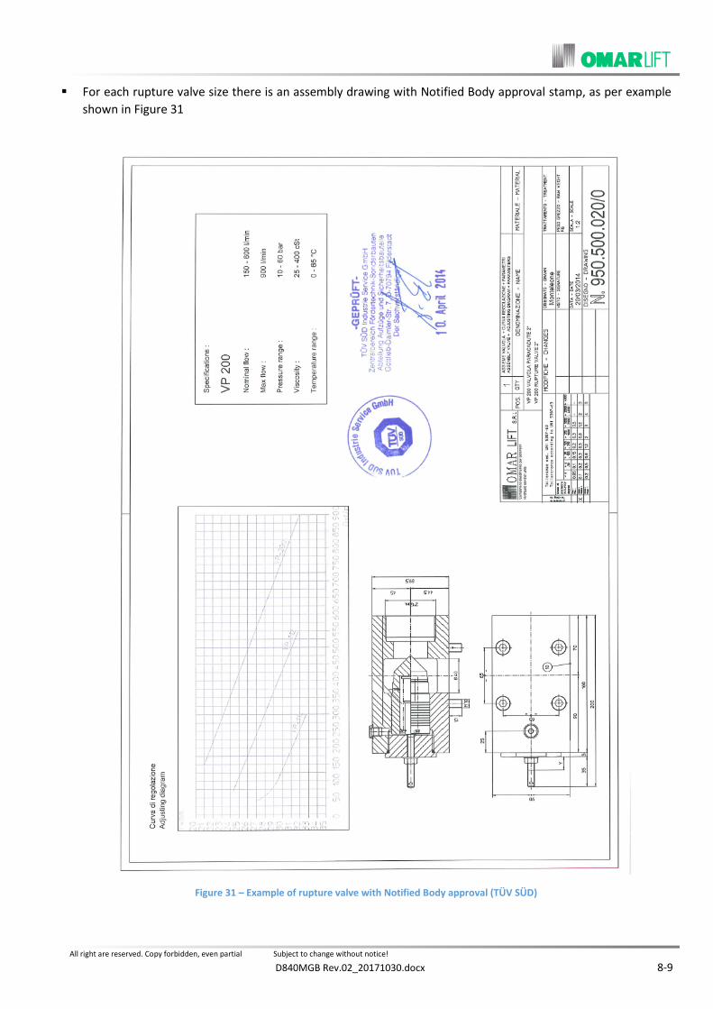
All right are reserved. Copy forbidden, even partial Subject to change without notice!
D840MGB Rev.02_20171030.docx 8-9
For each rupture valve size there is an assembly drawing with Notified Body approval stamp, as per example
shown in Figure 31
Figure 31 – Example of rupture valve with Notified Body approval (TÜV SÜD)


All right are reserved. Copy forbidden, even partial Subject to change without notice!
D840MGB Rev.02_20171030.docx 9-1
OPTIONALS ACCESSORIES 9
VALVE HEATING RESISTOR 9.1
- The small resistor to heat the valve block is 60 W powerful. Its feeding tension can be 220/230 V 50 Hz or
380/400 V 50 Hz.
The valve heating resistor does not have a thermostat and consequently is always active. During summer time, it is proper to switch it off. Figure 32 shows where the resistor has to be inserted on the valve and how.
Figure 32 – Installation of the valve heating resistor
OIL HEATING RESISTOR 9.2
- The resistor to be installed in the tank to heat the oil is 500-W powerful. Its feeding tension can be 220/230 V.
50 Hz or 380/400 V. 50Hz.
The oil heating resistor is supplied with an internal thermostat of switching on and switching off, not adjustable. Results are better when the car is taken back to the ground floor after the first 8/15 minutes that the installation is standstill. Generally speaking the thermostat switches on of the resistor for a temperature below 13-15°C and switches off over 20-25°C. A safety device intervenes protection in case of overtemperature limit for malfunction of the work thermostat.
A request can be supplied configurations with separate thermostat adjustable.
Figure 33 shows the installation of the oil heating resistor in the tank.
Figure 33 – Installation of the oil heating resistor

All right are reserved. Copy forbidden, even partial Subject to change without notice!
9-2 D840MGB Rev.02_20171030.docx
OIL COOLING 9.3
GENERAL INFORMATION 9.3.1
Oil needs to be cooled in installations with high traffic. According to the different situations, it is suggested to use
an oil cooling system in installations with more than 50-70 travels per hour. The oil cooling system can be with air
or with water and is available in sizes: 7; 10,5; 16,4 or 21 kW. The main parts of an oil cooling system are:
- An electro-pump for the forced oil running;
- An heat exchanger (oil/air-oil/water);
- A thermostat to control the temperature;
The following table suggests how a cooling system has to be chosen:
PUMP UNIT MOTOR TYPES OF COOLING SYSTEMS
Up to 25/30 HP = 18,4/22 kW 10,5 kW = 9000 kcal/h
More than 25/30 HP = 18,4/22 kW 16,4-21 kW =
14000-180001 kcal/h
The thermal exchange values, in kW or kcal/h for the two types, refer to temperature difference between oil and
air oil and water of 40°C. (i.e.: oil 60°C – air or water 20°C). Obviously, if the temperature difference between oil
and air or oil and water is low , the thermal exchange will be lower too.
COOLING SYSTEM WITH AIR 9.3.2
Figure 34 shows the connection diagrams between pump unit and heat exchanger. Figure 35 shows the electrical
connection diagram.
Figure 34 - Connection scheme

All right are reserved. Copy forbidden, even partial Subject to change without notice!
D840MGB Rev.02_20171030.docx 9-3
Figure 35 – Installation of the oil heating resistor
The air heat exchanger has not to be put near the oil tank.
The air heat exchanger has to suck fresh air and has to be put preferably near a window or an air passage connected to the outside. The room where the heat exchanger has been located, has to be constantly ventilated.
The heat exchanger has to be positioned preferably on the same floor as the pump unit, about 3 m far from the tank.
- Noise 68/71 dBA about.
- For further information see the technical catalogue or the specific operating instructions.
COOLING SYSTEM WITH WATER 9.3.3
The cooling systems with water are generally connected directly to the tank when the pump until is being built
(see Figure 36). Figure 37 shows the electrical connection diagram.
Figure 36 - Connection scheme

All right are reserved. Copy forbidden, even partial Subject to change without notice!
9-4 D840MGB Rev.02_20171030.docx
Figure 37 – Electrical connection diagram of the oil cooling system with water
If the cooling system with water is supplied alone – without pump unit – the customer will have to connect it to
the pump unit.
The holes for the oil suction have to be as far as possible from the holes for fresh oil return to the tank. While the hole for the thermostat has to be close to the hot oil suction.
The water connections have to respect the measures shown by Figure 36, or the installation real ones.
- Noise will be lower than 60 dBA.
- For further information see the technical catalogue or the specific operating instructions.
MICRO-LEVELLING UPWARD WITH SUBSIDIARY MOTOR 9.4
The micro-levelling device is used in big installations to take back the car to the floor without activating the main
motor which, because of its big power, would take longer and huge power absorption. The micro-levelling device
is made up by a subsidiary motor-pump group and a safety valve assembled outside the tank (see Figure 38).
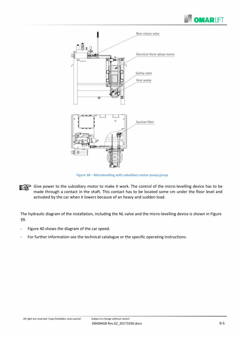
All right are reserved. Copy forbidden, even partial Subject to change without notice!
D840MGB Rev.02_20171030.docx 9-5
Figure 38 – Microlevelling with subsidiary motor-pump group
Give power to the subsidiary motor to make it work. The control of the micro-levelling device has to be made through a contact in the shaft. This contact has to be located some cm under the floor level and activated by the car when it lowers because of an heavy and sudden load.
The hydraulic diagram of the installation, including the NL valve and the micro-levelling device is shown in Figure
39.
- Figure 40 shows the diagram of the car speed.
- For further information see the technical catalogue or the specific operating instructions.

All right are reserved. Copy forbidden, even partial Subject to change without notice!
9-6 D840MGB Rev.02_20171030.docx
Figure 39 – Hydraulic diagram with microlevelling device and “NL” valve
LEGENDA
VR = Non-return valve.
VM = Max pressure valve.
VS = Safety valve.
VRF = Flow-regulation valve.
VRA = Down travel balancing valve.
VBP = Pilot block valve.
EVD = Down travel electrovalve.
EVR = Flow-regulator electrovalve.
EVS = Up travel electrovalve.
VEM = Emergency.
VP = Rupture valve.
FR = Shut-off valve.
R = Shut-off valve and attack fi” Gas for the control manometer.
M = Manometer.
PM = Hand pump.
PR = Inlet for the pressure switch
ML = Microlevelling with subsidiary motor-pump group

All right are reserved. Copy forbidden, even partial Subject to change without notice!
D840MGB Rev.02_20171030.docx 9-7
-
- - UPWARD TRAVEL: subsidiary motor-pump group connected.
- - STOP DURING UPWARD TRAVEL: stop subsidiary motor.
Figure 40 – Car speed diagram


All right are reserved. Copy forbidden, even partial Subject to change without notice!
D840MGB Rev.02_20171030.docx 10-1
MAINTENANCE OF THE HYDRAULIC INSTALLATION 10
GENERAL INFORMATION 10.1
Generally, the hydraulic components are not subject to a frequent wear, they are safe and need few maintenance
operations. These results are reached when the components are chosen and dimensioned correctly on the basis
of the installation characteristics. Moreover the hydraulic oil has to suit with the room temperature and the
installation traffic conditions.
It is however necessary to make, according to the established times, the test and maintenance operations reported in the periodical recommended maintenance sheet and get rid of the detected faults immediately.
In case irregularities or faults, which can jeopardise the safety of people and installations, are met on the components, the installation has to be put out of service until the defective parts are repaired or replaced.
OIL LOSSES AND CAR LOWERING 10.2
Oil losses in the hydraulic circuit cause the car lowering with respect to the floor level even when controls, which
make the electrical anti-creep system intervene, are absent.
Please remember that the car lowering can also be caused by the oil cooling. This phenomenon is evident when the installation stops, oil is very hot and the room temperature is much lower than the oil one.
At these conditions the electrical anti-creep system has no to be deactivated, since the car lowering could be very important.
- Oil losses in the hydraulic circuit can be due to the following causes.
LOSSES ALONG THE PIPES 10.2.1
Losses are usually localised in the joints of the rigid pipes or along the flexible hoses. These losses can be visually
detected. They can be eliminated tightening the fitting nuts, joining the pipes correctly or replacing the flexible
hoses.
CYLINDER LOSSES 10.2.2
Big cylinder losses are due to wear or to damaged seals, which are located in the head of the cylinder itself. The
oil coming out from the cylinder is collected in a proper room and, through a PVC pipe, conveyed to a transparent
tank. It is necessary that the room inside the cylinder head and the hole leading to the PVC pipe are not
obstructed by dirt. The cylinder losses depend on the traffic intensity and seal wear.
When losses are more than one or two litres per month, it is better to replace the cylinder seals.
- In underground direct acting cylinders, oil losses can be due to chemical or electrical corrosion of the cylinder.
This phenomenon provokes the continuous decreasing of the oil level in the tank.
underground cylinder have to be put inside a protection wrapping to avoid ground and groundwater pollution.
In case oil soaks into the ground, the underground cylinder has to be disassembled and replaced.

All right are reserved. Copy forbidden, even partial Subject to change without notice!
10-2 D840MGB Rev.02_20171030.docx
LOSSES INSIDE THE VALVE GROUP 10.2.3
When the installation is motionless at floor and the electro-valves are disconnected, the load pressure involves
the part of the valve shown in Figure 41 with crossed lines.
Figure 41 – Part of the valve remaining under pressure when the installation is still (hatching)
The valve sealing is proved as follows:
- When the valve temperature is the same as the room temperature, close the main line shut-off valve and
increase the pressure, using the hand pump, until twice the static pressure.
- If there are no losses in the valve, pressure keeps constant or decreases slowly, not more than 5/6 bar during
the first 3/4 minutes and tends to settle.
- If there are losses in the valve, pressure decreases rapidly, more than 5/6 bar during the first 3/4 minutes and
goes on decreasing up to the static pressure value.
- The valve components which can be involved in possible losses are the following:
a) Hand pump.
The hand pump sealing is assured by a ball. Activate the hand pump, leave the lever against the valve and
wait for some minutes to check the sealing. In case of losses, the lever goes back automatically.

All right are reserved. Copy forbidden, even partial Subject to change without notice!
D840MGB Rev.02_20171030.docx 10-3
b) Hand emergency valve VEM.
The sealing of the hand pump is also assured by a ball whose working can be jeopardised by dirt laying
between seat and ball. Carry out a first check by removing the moving half-cover of the tank and look under
the valve. Every time the emergency button is activated, an oil outflow will be noted.
This outflow has to stop when the button is left. In case this does not happen, there can be losses from the
emergency valves or losses from the electro-valve EVD which has the same discharge point.
The following checks, including the ones explained at point c), have to be carried out with pressure inside the valve. Consequently, operate very carefully. Check the emergency valve (see Figure 42) sealing, by unscrewing completely the emergency group starting from the hexagon. Dry well the oil remained inside the hole and check that no further oil comes out from the ball.
Figure 42 – Check of emergency valve working
If oil losses are detected through the ball, the whole down travel block needs to be replaced or repaired – see the following c) point.
c) Down travel electro-valve EVD.
The sealing ball of the down travel valve (see Figure 43) can remain lightly open and loose oil for different
reasons:
- Small metal particles or dirt lay inside the coil, between quill and cursor, delaying or preventing the return
movement of the coil cursor. Remove the coil, unscrew the mechanical part of EVD, shake it with the hand to
be sure that the piston is running free inside. Otherwise, replace it.
Figure 43 – Downward electrovalve EVD P
P

All right are reserved. Copy forbidden, even partial Subject to change without notice!
10-4 D840MGB Rev.02_20171030.docx
- The coil EVD button has got mechanically caught, after having been activated manually with a screwdriver.
The coil cursor can not get back to its motionless position. In this case, remove the coil, unscrew the
mechanical part of EVD and push back its piston completely.
- Some metal particles lay between ball and sealing seat, preventing the closing or damaging the sealing seat.
Check the electro-valve EVD sealing by unscrewing the mechanical part of the coil and removing the needle
and the brass seat. Finally, after having dried the oil inside the hole, check that no further oil comes out from
the ball. Each operation previously described needs to have a perfect closing of the ball. Otherwise, oil losses
occur under valve where hand emergency losses meet.
In case oil losses occur through EVD ball, replace the whole down travel block or repair the sealing seat. The following procedure is valid also in case the hand emergency sealing seat needs to be repaired. – see point b).
Close the main line shut-off valve, unscrew the screw n°3 (rod counter-pressure) and push hand emergency button to take pressure to zero.
- Unscrew the fixing screw of the block to inspect the seats of the balls.
- Remove the stop ring (type Seeger) which blocks spring and ball.
- Inspect the seats. In case they are scored or faulty, repair them. Position the balls in their proper place and
clinch using a proper punch.
WARNING: do not hammer strongly, because seats are out of aluminium and can break. If possible, replace the balls used to clinch the seats.
- Reassemble properly all the components, reassemble the block and check the sealing.
d) Piloted rupture valve VBP
The VBP valve (non-return valve) has to keep the main line closed when the car is motionless. The perfect
sealing is guaranteed by a seal laying between the two parts which compose its piston. This seal wears with
the passing of the time and can be damaged by metal particles which engrave it and hinder its sealing
because they come between seat and seal. The closing can also be slowed by the bad running of the VBP
piston because of dirt and hindered by the faulty closing of the electro-valve EVD. The oil lost through the
VBP valve goes directly to the tank through the discharge pipe and can be checked only thanks to it.
Operate as follows to get rid from VBP losses.
- Check that VBP piston runs well and, if necessary, remove dirt and clean with a thin cloth.
- Check that the electro-valve EVD closes perfectly, when the coil is disconnected (see previous point c).
- Replace the VBP seal as shown in Figure 44:

All right are reserved. Copy forbidden, even partial Subject to change without notice!
D840MGB Rev.02_20171030.docx 10-5
Figure 44 – Replacement of seal VBP and cleaning of the filters
Close the main line shut-off valve.
Unscrew the screw n° 3 for rod counter-pressure and take pressure back to zero using the hand manoeuvre
button.
Remove the hand pump to reach VBP piston.
Unscrew the screw which holds the two parts of the piston tight and replace the seal laying between them.
Be careful to position it in the right way.
Reassemble all the parts paying attention to the O’Ring which lays between the valve and the hand pump.
SEAL REPLACEMENT ON A SINGLE-STAGE CYLINDER 10.3
The seals of a normal cylinder are positioned on the cylinder head (see Figure 45). Seal replacement consists in
replacing the three sealing parts:
- The main seal of the rod;
- The sealing O’ring on the iron ring thread;
- The rod scraper.
The iron ring which holds the seal is screwed. The unscrewing operation is facilitated by 4 blind threaded holes
M10. It is possible to unscrew the iron ring introducing 4 screws in the 4 holes or using proper hook spanners
which can be found on the market.
Before replacing the seal, control the rod surface and get rid of the possible irregularities, such as scores or bruises which could damage the new seals.
- Take the car in upper extra travel and the cylinder in upper end position.
Carefully take a place near the head and, if necessary, sling with a rope to be able to work safely and freely.
- Check the rod surface fi metre by fi metre, all long its length, making a slow down travel with and emergency.
Get rid of any irregularities found visually or touching it by using a thin abrasive paper. In case scores are deep or damages are important, fix the paper on a wooden support.
- After having controlled the last half metre of the rod, operate to replace the seals.

All right are reserved. Copy forbidden, even partial Subject to change without notice!
10-6 D840MGB Rev.02_20171030.docx
Block the car, using stops in the most comfortable position. In case of indirect acting installations, block with a stop even the support of the pulley.
- In case of direct acting installation disconnect the rod from the frame. While in case of indirect acting ones,
disconnect the rod from the pulley.
Clean the cylinder head, unscrew completely the screw n° 3 of the counter-pressure. Make the rod break back until the manometer shown pressure = zero.
- Unscrew the threaded iron ring holding the seals.
- Remove the old seal, the O’ring on the thread and the scraper.
- Control and clean the guide rings and position them in their place. (Have access to the second guide ring by
taking out the metal bush, laying under the iron ring, screwing two small screws M3 on the bush itself to lift
it).
- Clean and control the seats, reassemble the new seals, paying attention not to damage them and position
them in the same way as the old ones. (The writing “PRESSURE SIDE”, if existing, has to be turned toward the
cylinder inside!).
- Reassemble the bush (in case it has been taken out), screw again the iron ring with the new seal, purge the
air and put the installation into action.
Figure 45 – Replacement of the seal on a one-stage cylinder

All right are reserved. Copy forbidden, even partial Subject to change without notice!
D840MGB Rev.02_20171030.docx 10-7
AIR IN THE OIL 10.4
There is air in the oil in case of foam in the tank mainly during the down travel phase and in case the oil becomes
whitish. Negatives effects on the installation are caused by the increase of the oil compressibility factor. The most
common effects are the following ones:
- When the installation is motionless at the floor, the car lowers when loaded and goes up when unloaded.
- When the installation moves, strong oscillations, pump noise and irregularities during the movement are
noted.
- Air in the oil can be due to: insufficient air purge during the first filling of the circuit, too low level of oil in the
tank, the discharge pipe is not connected to the have any more, etc.
Operate as follows to get rid of the air from the circuit:
- When the oil is hot, position the car low on the dampers and discharge pressure with the hand button,
unscrewing the screw n°3 of counter-pressure too.
- Remove the cylinder vent screw and leave everything rest for about 8/10 hours. In this way the air in the oil
will go up and the air in the tank will be automatically released. Now, purge the air from the cylinder as
follows.
- Leave the cylinder vent screw open and switch off the high speed coil EVR.
- Activate the motor one or two times for few seconds until clear oil comes out from the vent screw without
air.
- Close the cylinder vent screw, take back the screw n°3 at its original position, make an up travel with low
speed, checking that the ropes are well positioned in the pulley gorges.
- If necessary, repeat this operation after a few days and above all try to get rid of the causes which have led to
the air problem.
FILTER CLEANING INSIDE THE VALVE GROUP 10.5
- During the general overhaul or in case working anomalies occur, clean all the filters connected to the electro-
valves and shown in Figure 44.
- In particular, in case the putting under pressure and the start upwards result to be difficult, clean the filter
EVS of the up travel block, shown in Figure 46, removing first the cap and then unscrewing the filter with a
screwdriver.
- Operate as follows to clean or replace the cartridge of the shut-off valve: unscrew the screw n°3 and
discharge pressure; then unscrew the filter bottom to have access to the cartridge.

All right are reserved. Copy forbidden, even partial Subject to change without notice!
10-8 D840MGB Rev.02_20171030.docx
Figure 46 – Filter cleaning of EVS line
MINERAL OIL DETERIORATION 10.6
It is difficult to calculate how fast the mineral oil deterioriorates: this time depends on the work conditions, such
as temperature and pressure, and from the real working hours.
- Dust and moisture in the environment get into the oil directly or because of condensate through the air
which enters into the tank during the up travel phase. They can deteriorate oil very fast. When this fact
occurs, it is necessary to stop the installation at the lowest floor, let the oil settle and discharge water and dirt
from the discharge hole under the tank. Specialised companies can also centrifuge and filter hot oil.
- Pressure and temperature in the hydraulic installations are not so high and do not have a negative influence
on the oil life, unless the oil itself is continuously subject to overheating or the motor burns inside it.
- The real working hours of a good oil, without the above mentioned factors, go from 3000 to 5000 max. about.
These limits are however influenced by the two above mentioned factors.
- Every year at least and however every 2000 working hours, check the oil preservation condition: smell,
colour, foam, dirt particles, etc. if necessary, contact a specialised analysis laboratory
In case the oil needs to be replaced, pay attention to the anti-pollution regulations in force.
ELECTRICAL ANTI-CREEP SYSTEM 10.7
During controls on the installation, check the working of the anti-creep system, activating the hand emergency at
every floor.
EMERGENCY LOWERING WITH THE BATTERY 10.8
Check periodically the battery efficiency, switching off the feeding tension.
PLATES, DIAGRAMS, INSTRUCTIONS 10.9
Check periodically the presence of plates, diagrams and instructions where requested.
SEAL REPLACEMENT ON TELESCOPIC CYLINDERS 10.10
GENERAL INFORMATION 10.10.1
In synchronised telescopic cylinders, the oil of the pump unit acts only on the piston of the biggest rod. The other
rods move thanks to the oil laying inside the cylinder rooms which, during the normal working, have no contact
with the pump unit. The internal volumes of these rooms allow the upper rods to run their complete travel. For a
correct working, the internal rooms of the synchronised telescopic cylinder need to be filled with oil and kept
filled. The oil lost in the internal rooms during the working make the cylinder loose its synchronism. For this

All right are reserved. Copy forbidden, even partial Subject to change without notice!
D840MGB Rev.02_20171030.docx 10-9
reason, the seals of the cylinder have a very important role in keeping the cylinder synchronism. Deep attention
has to be paid to the preservation of the rods and to the oil cleaning.
- Every head of a telescopic cylinder has its own set of seals to avoid oil losses toward the outside.
- The smaller cylinder has a plunging piston without seals.
- The piston of the bigger rods (one for two-stage telescopic cylinders and two for three-stage telescopic
cylinders) have a seal to prevent the oil from going from the upper room to the lower one.
- The piston of the big rods have not only a sealing seal, but also a small valve which is normally closed and
opens only when the cylinder is completely closed. At this condition, this small valve allows the filling of the
rooms. (see paragraph 5.3 “FILLING AND SYNCHRONISATION OF TELESCOPIC CYLINDERS”).
- Reduced displacements of the rods can occur in telescopic cylinders. They are due to the different pressure
inside the rooms and to the different temperature of the oil inside the rooms. They are normally solved
thanks to a correct distribution of the extra-travels, as recommended:
TOTAL EXTRA-TRAVEL FOR TWO-STAGE TELESCOPIC CYLINDER: MIN. 500 mm
TOTAL EXTRA-TRAVEL FOR THREE-STAGE TELESCOPIC CYLINDER: MIN. 600 mm
- Losses of dynamism, due to the rod movement, and losses due to the seal wear cause problems to the
installation synchronism with the passing of the time, problems which can not be solved by the extra-travels.
The synchronisation needs now to be renewed, as described in paragraph n° 5.3.
- In case the cylinder continuously looses its synchronism, the renewal of the synchronisation is not enough an
more. It is now necessary to replace the seals.
SEAL REPLACEMENT ON TWO-STAGE TELESCOPIC CYLINDERS, TYPE CT-2 10.10.2
In case of two-stage telescopic cylinders Figure 47, the involved seals are:
N° 1 internal seal, on the piston of rod n° 2
N° 1 set of seals – head n° 1
N° 1 set of seals – head n° 2
The following tools are needed to replace all the seals, included the piston one: - N° 1 hoist to unthread the rods out of the cylinders (the hoist capacity has to be at least the same as
the weight of the most heavy rod); - N° 1 or more recipients to collect the oil; - N° 1 suction pump to suck oil from the cylinder inside.
How to operate:
Block the car with strops in the more comfortable position: up, in case of direct central acting installations; under the cylinder head, in case of direct side acting cylinders.
- Remove the 4 screws, which block the upper plate “A” to the frame, remove the guide arms, if existing and fix
under the head “C” a tool (screwer or bridle) needed to keep the rod still, when its head will be disassembled.
- Clean the heads and make the rods break back completely with hand manoeuvre. Unscrew the screw n°3 to
take pressure to zero.
- Unscrew the screw “B” of the articulation and remove plate “A”.

All right are reserved. Copy forbidden, even partial Subject to change without notice!
10-10 D840MGB Rev.02_20171030.docx
- Release the 4 lock nuts and the 4 screws “H” which block the heads “C” and “D”. Unscrew the head “C” and
unthread it from the rod.
- Re-position the upper plate “A” to be able to unthread the rod n°1. Lean it vertically in the shaft, paying
attention not to damage it.
- Remove the oil PVC pipe, unscrew the head “D” and unthread it from the rod.
Figure 47 – Seal replacement on telescopic cylinder CT-2
Before taking out the rod n°2, it is necessary to open the hydraulic circuit to allow the air to get into while the rod is lifted. In case of direct central acting installations, remove the fitting on the shut-off valve, while in case of direct side acting installations, unscrew the cap “F” of the cylinder. The oil lost during this operation has to be promptly collected.
- Screw again the head “C” to be allowed to hook the rod n°2 and take it out slowly to avoid leakage of oil
which will be sucked by the suction pump.
- Replace seal “1” on the piston of the rod n°2. Respect the position of the different parts, as per the original
seal. The replacement of the O’ring of the filling valve is difficult, but, since this seal is static, no replacement
is needed.

All right are reserved. Copy forbidden, even partial Subject to change without notice!
D840MGB Rev.02_20171030.docx 10-11
- Check carefully the whole surface of the two rods; get rid of any bruise or scratch using a fine abrasive paper,
grain 400 ÷ 600.
- Reassemble the rod n°2 into the cylinder. Be careful not to damage the seal.
- Replace the seal, the scraper and the O’ring of the head n °2, removing the flange which block the seal “E”.
Reassemble the head n°2 and screw again the two block screws together with their nuts.
- Reassemble rod n°1 inserting it in rod n°2.
- Replace the seal, the scraper and the O’ring of the head n°1, removing the flange which block the seal “E”.
Reassemble the head n°1 and screw again the two block screws together with their nuts.
- Reassemble plate “A” and fix it with the screw “B” and its components.
- Close the hydraulic circuit, put back the cap “F” or screw the fitting of the shut-off valve, remove the screwer
and make the cylinder close on itself to fill up and purge the air.
- Fill up and purge the air of the cylinder, very slow at low speed, removing the vent caps “G” of the two heads.
Close the vents only when clear oil without air comes out from them.
Reassemble the guide arms, if existing and make the cylinder rise until it leans against the car which could finally be reconnected the plate “A” with its 4 screws.
- After the first travel, check the synchronism and, if necessary, do again the filling up and the
synchronisation, as explained at paragraph 5.3.
SEAL REPLACEMENT ON THREE- STAGE TELESCOPIC CYLINDERS, TYPE CT-3 10.10.3
In case of three-stage telescopic cylinders, Figure 48, the involved seals are:
- N° 1 internal seal, on the piston of rod n°2
- N° 1 internal seal, on the piston of rod n°3
- N° 1 set of seals – head n° 1
- N° 1 set of seals – head n° 2
- N° 1 set of seals – head n° 3
The following tools are needed to replace all the seals, included the internal seals of rods n°2 and 3: - N° 1 hoist to unthread the rods out of the cylinders (the hoist capacity has to be at least the same
as the weight of the most heavy rod). - N° 1 or more recipients to collect the oil. - N° 1 suction pump to suck oil from the cylinder inside

All right are reserved. Copy forbidden, even partial Subject to change without notice!
10-12 D840MGB Rev.02_20171030.docx
How to operate:
Block the car with stops in the more comfortable position: up, in case of direct central acting installations; under the cylinder head in case of direct side acting cylinders.
- Remove the 4 screws which block the upper plate “A” to the frame, remove the guide arms, if existing and fix
under the heads “C” and “D” a tool (screwer or bridle) needed to keep the rods still, when their heads will be
disassembled.
- Clean the heads and make the rods break back completely with hand manoeuvre. Unscrew the screw n°3 to
take pressure to zero.
- Unscrew the screw “B” of the articulation and remove plate “A”.
- Release the lock nuts and the 6 screws “H” which block the three heads “C” – “D”and “E”. unscrew the head
“C” and unthread it from the rod.
- Re-position the upper plate “A” to be able to unthread the rod n° 1. Lean it vertically in the shaft, paying
attention not to damage it.
- Unscrew the head “D”, after having checked that the two screws “H” are released, and unthread it from the
rod n°2.
Before taking out the remaining rods, it is necessary to open the hydraulic circuit to allow the air to get into while the rods are lifted. In case of direct central acting installations, remove the fitting on the shut-off valve, while in case of direct side acting installations, unscrew the cap “F” of the cylinder. The oil lost during this operation has to be promptly collected.
- Screw the head “C” to hook the rod n°2 and take it out slowly to avoid oil leakage which will be sucked by the
suction pump. Lean this rod vertically in the shaft, protect it and pay attention not to damage it.
- Remove the oil PVC pipe, unscrew the head “E” and unthread it from the rod n°3, after having checked that
the two block screws “H” have been released.
- Screw the head “D” to hook the rod n°3 and take it out slowly to avoid oil leakage which will be sucked by the
suction pump.
- Replace the seal “2” on the piston of the third rod. Respect the position of the different parts, as per the
original seal. The replacement of the O’rings of the filling valves is difficult, but since this seal is static, no
replacement is needed.
- Check carefully the whole surface of the rods n°3; get rid of any bruise or scratch using a fine abrasive paper,
grain 400 ÷ 600.
- Reassemble the rod n°3 into the cylinder. Be careful not to damage the seal.
- Replace the seal, the scraper and the O’ring of the head n°3, removing the flange which block the seal “I”.
Reassemble the head n°3 and screw again the two block screws together with their nuts.
- Replace the seal “1” on the piston of rod n° 2. Respect the position of the different parts, as per the original
seal

All right are reserved. Copy forbidden, even partial Subject to change without notice!
D840MGB Rev.02_20171030.docx 10-13
Figure 48 – Seal replacement on telescopic cylinder CT-3
- Check carefully the whole surface of the rods n°1; get rid of any bruise or scratch using a fine abrasive paper,
grain 400-600.
- Reassemble rod n°2 into the cylinder. Be careful not to damage the seal.
- Replace the seal, the scraper and the O’ring of the head n°2, removing the flange which block the seal “I”.
Reassemble the head n°2 and screw again the two block screws together with their nuts.
- Check carefully the whole surface of the rods n°1; get rid of any bruise or scratch using a fine abrasive paper,
grain 400 ÷ 600.
- Reassemble the rod n°1 inserting it in rod n°2.
- Replace the seal, the scraper and the O’ring of the head n°1, removing the flange which block the seal “I”.
Reassemble the head n°1 and screw again the two block screws together with their nuts.
- Reassemble plate “A” and fix it with the screw “B” and its components.
- Close the hydraulic circuit, put back the cap “F” or screw the fitting of the shut-off valve, remove the screwers
and make the cylinder close on itself to fill up and purge the air.
- Fill up and purge the air of the cylinder, very slow at low speed, removing the vent caps “G” of the three
heads. Close the vents only when clear oil without air comes out from them.
Reassemble the guide arms, if existing, and make the cylinder rise until it leans against the car which could finally be reconnected the plate “A” with its 4 screws. After the first travel, check the synchronism and, if necessary, do again the filling up and the synchronisation, as explained at paragraph 5.3

All right are reserved. Copy forbidden, even partial Subject to change without notice!
10-14 D840MGB Rev.02_20171030.docx
POSSIBLE PROBLEMS AND THEIR SOLUTION 10.11
1) The lift does not go up neither at low speed not at high speed.
- Check the adjusting pressure – screw n°1.
Close the line shut-off valve, discharge the static pressure with the hand button and activate the motor. The
adjusting pressure has to be 1,4 times the max static pressure with a full load.
If pressure is too low, increase until the needed value by screwing n°1 and test.
If pressure does not increase or does not reach the needed value, operate as follows.
- Control the motor-pump group, verifying that, when the motor works correctly turning clockwise, all the oil
of the pump goes back to the tank through the return pipe.
- Control that the pipe connecting pump and valve and the silencer are not unscrewed or broken.
- Check the valves with coil EVS (delta-star): the coil has not to be burnt or switched off and had to be correctly
fed. If necessary, try to push its piston with a screwdriver, without scratching its seat.
- Check that the screw n°7 is sufficiently open and, if necessary, try to unscrew by a few turns.
If no result is obtained, switch off the main valve and discharge the pressure pushing the hand button. Then operate as follows:
- Check and clean the filter of EVS line, as explained at paragraph 10.5.
- Remove the cap laying near the hand pump. Check that piston VM of the max pressure valve moves free and
is not blocked by dirt (see Figure 49).
Figure 49 – NL valve section
- In case of installations with coil EVS, disassemble the – Δ group, unscrew the mechanical part of the coil,
shake it strongly to verify if the piston inside moves free (shake it strongly, because the piston is braked by a
spring). In case of installations without coil EVS, remove the cap EVS. For both the cases, clean the brass
piston, clean the parts disassembled and reassemble them (see Figure 50).
- Once the needed pressure has been reached, check the adjusting values of screw n°1 and screw n°7, as
shown at paragraphs 8.2.1 and 8.2.2.

All right are reserved. Copy forbidden, even partial Subject to change without notice!
D840MGB Rev.02_20171030.docx 10-15
Figure 50 – EVS with and without coil: sections
2) The lift goes up slowly and its dynamic pressure is strongly higher than the static one
- Verify that the car moves free, without forcing on the guides.
- Verify that the guides are parallel and their distance is constant all along their length.
- Verify that the cylinder and the completely unthreaded rod are parallel to the guides all along the length.
- Check that the screw n°6 of the valve block is not too much screwed.
- Verify that the regulation screw of the rupture valve is not too much screwed.
3) The lift moves at low speed both upward and downward.
- Check that the coil EVR is not burnt or switched off and is correctly fed. If necessary, try to push its piston
with a screwdriver, without scratching its seat.
- Be sure that piston VRF is not blocked: remove the flange supporting the screw n°6 (see Figure 49).
- Clean the discharge filter of EVR (see Figure 46) and remove dirt from the internal hole.
4) The lift does not start downward
- Verify that the coil EVD is not burnt or switched off and is correctly fed.
- Verify that the min. static pressure is higher than 10/12 bar. Load the car if needed.
- Verify that the rupture valve on the cylinder has not intervened. If necessary, unlock it with the hand pump.
- Verify that the screw n°8 is not completely unscrewed.
- Verify that the piston of the valve EVS is not mechanically blocked in the down piston.
5) The lift starts downward and stops immediately.
- Check that the rupture valve of the cylinder is not too closed. If it is, the valve intervenes immediately and the
pressure of the manometer goes to zero.
- Check that the poppet / mushroom valve VR is not open because of dirt. In this case the valve EVS blocks. If
the cap of the EVS filter is removed, oil comes out when down travel is activated (see Figure 46).
- Operate as follows to have access to VR: disconnect the pipe which connect the pump to the valve, lift the
cover which supports the valve block and unscrew the fitting at the entrance of the valve itself.
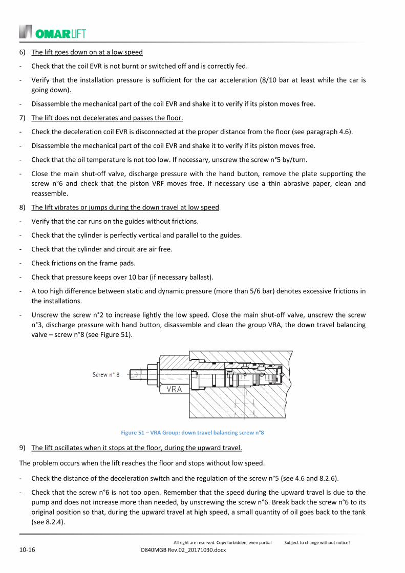
All right are reserved. Copy forbidden, even partial Subject to change without notice!
10-16 D840MGB Rev.02_20171030.docx
6) The lift goes down on at a low speed
- Check that the coil EVR is not burnt or switched off and is correctly fed.
- Verify that the installation pressure is sufficient for the car acceleration (8/10 bar at least while the car is
going down).
- Disassemble the mechanical part of the coil EVR and shake it to verify if its piston moves free.
7) The lift does not decelerates and passes the floor.
- Check the deceleration coil EVR is disconnected at the proper distance from the floor (see paragraph 4.6).
- Disassemble the mechanical part of the coil EVR and shake it to verify if its piston moves free.
- Check that the oil temperature is not too low. If necessary, unscrew the screw n°5 by/turn.
- Close the main shut-off valve, discharge pressure with the hand button, remove the plate supporting the
screw n°6 and check that the piston VRF moves free. If necessary use a thin abrasive paper, clean and
reassemble.
8) The lift vibrates or jumps during the down travel at low speed
- Verify that the car runs on the guides without frictions.
- Check that the cylinder is perfectly vertical and parallel to the guides.
- Check that the cylinder and circuit are air free.
- Check frictions on the frame pads.
- Check that pressure keeps over 10 bar (if necessary ballast).
- A too high difference between static and dynamic pressure (more than 5/6 bar) denotes excessive frictions in
the installations.
- Unscrew the screw n°2 to increase lightly the low speed. Close the main shut-off valve, unscrew the screw
n°3, discharge pressure with hand button, disassemble and clean the group VRA, the down travel balancing
valve – screw n°8 (see Figure 51).
Figure 51 – VRA Group: down travel balancing screw n°8
9) The lift oscillates when it stops at the floor, during the upward travel.
The problem occurs when the lift reaches the floor and stops without low speed.
- Check the distance of the deceleration switch and the regulation of the screw n°5 (see 4.6 and 8.2.6).
- Check that the screw n°6 is not too open. Remember that the speed during the upward travel is due to the
pump and does not increase more than needed, by unscrewing the screw n°6. Break back the screw n°6 to its
original position so that, during the upward travel at high speed, a small quantity of oil goes back to the tank
(see 8.2.4).

All right are reserved. Copy forbidden, even partial Subject to change without notice!
D840MGB Rev.02_20171030.docx 10-17
VALVE MODIFICATION: FROM DIRECT START TO – Δ FOR THE MOTOR ACTIVATION WITH 10.12
SOFT STARTER OR – Δ
The valve to be transformed will have only the double coil for the down travel and the simple coil for the high
speed.
- Clean the paint all around the cap “A” and the screw “B”(see Figure 52) of the upward block, using a solvent.
- Remove the cap “A” with its seal and the small screw “B”.
Figure 52 – Up travel block for direct start
Clean the remaining paint well. Be careful not to put it inside the open holes.
Assemble the – Δ device on “A” cap place (Figure 53), without closing the hole of the screw “B”:

All right are reserved. Copy forbidden, even partial Subject to change without notice!
10-18 D840MGB Rev.02_20171030.docx
Figure 53 - – Δ start or soft starter

All right are reserved. Copy forbidden, even partial Subject to change without notice!
D840MGB Rev.02_20171030.docx 10-19
PERIODICAL RECOMMENDED MAINTENANCE SHEET 10.13
PERIODICAL RECOMMENDED MAINTENANCE OPERATIONS
FOCUS ON THE OPERATING INSTRUCTIONS FOR THE PERIODICAL MAINTENANCE
INSTALLATION COMPLETED
EVERY 2 -3 MONTHS
EVERY YEAR EVERY 5 – 10
YEARS
CHECK OF THE SEALING OF THE CYLINDER SEALS 10.2.2 10.2.2 10.2.2
10.3
CHECK OF THE SEALING OF THE VALVE SEALS 10.2.3 10.2.3 10.2.3
CHECK OF THE PIPE SEALING 10.2.1 10.2.1
CHECK OF THE OIL LEVEL AND PRESERVATION 6.1 6.1 10.6 10.6
CLEANING OF THE SHUT – OFF VALVE AND VALVE FILTERS 10.5 10.5
CHECK OF THE PRESSURE ADJUSTING AT TWICE THE MAX STATIC PRESSURE
6.2
6.5
6.2
6.6
CHECK OF THE RUPTURE VALVE WORKING 7.3 7.3
CHECK OF THE ROPE ANTI – LOOSENING COUNTER - PRESSURE 6.7
8.2.7
6.7
8.2.7
CHECK OF THE ANTI – CREEP SYSTEM 10.7 10.7
CHECK OF THE EMERGENCY AND BATTERY 10.8 10.8
CHECK OF THE MOTOR FEEDING TIME 6.9 6.9
PLATES – DIAGRAMS - INSTRUCTIONS 10.9 10.9
GENERAL OVERHAUL xxxx


All right are reserved. Copy forbidden, even partial Subject to change without notice!
D840MGB Rev.02_20171030.docx 11-1
DIMENSIONS AND WEIGHTS – OIL FOR TELESCOPIC CYLINDERS 11
DIMENSIONS AND WEIGHTS OF THE PUMP UNITS 11.1
The weights of the pump units with shut-off valve are divided per kind of tank and do not consider the weight
differences of pumps and motors of different size. Consequently there is a are approx. calculated with a ± 5%
tolerance.
PUMP UNITS DIMENSIONS WITHOUT HDU
VALVE TYPE TANK TYPE
ENCUBRANCE DIMENSIONS [mm]
M1 M2
HORIZ FILTER. M2
VERT. FILTER M3 M4 M5 M6
NL - 210
110/S 300 95 0 702 360 700 140
135/S 300 95 0 902 360 700 155
210/S 400 129 51 810 360 830 110
320/S 460 160 70 950 360 950 110
450 700 150 - 952 360 1000 105
NL - 380
320/S 460 160 70 950 360 950 125
450 700 150 - 952 360 1000 130
680 800 140 - 1002 360 1250 165
NL - 600
680 800 140 - 1002 360 1250 165
900 800 140 - 1202 360 1250 165
1000 800 140 - 1302 360 1250 165

All right are reserved. Copy forbidden, even partial Subject to change without notice!
11-2 D840MGB Rev.02_20171030.docx
PUMP UNITS DIMENSIONS WITH HDU (UCM DEVICE)
WEIGHTS OF THE PUMP UNITS
.
NL + HDU INTEGRATED
VALVE TYPE TANK TYPE
ENCUBRANCE DIMENSIONS [mm]
M1 M2
HORIZ FILTER. M2
VERT. FILTER M3 M4 M5 M6
NL – 210 + HDU
INTEGRATED
110/S 300 - 0 702 360 700 162
135/S 300 - 0 902 360 700 162
210/S 400 - 0 810 360 830 165
320/S 460 - 0 950 360 950 320
450 700 - 0 952 360 1000 310
NL – 210 + HDU STAND
ALONE
110/S 300 600 - 702 360 700 161
135/S 300 600 - 902 360 700 161
210/S 400 305 80 810 360 830 114
320/S 460 100 15 950 360 950 320
450 700 130 40 952 360 1000 310
NL – 380 + HDU STAND
ALONE
320/S 460 175 85 950 360 950 295
450 700 210 95 952 360 1000 285
680 800 170 - 1002 360 1250 357
NL – 600 + HDU STAND
ALONE
680 800 180 - 1002 360 1250 478
900 800 180 - 1202 360 1250 478
1000 800 180 - 1302 360 1250 478
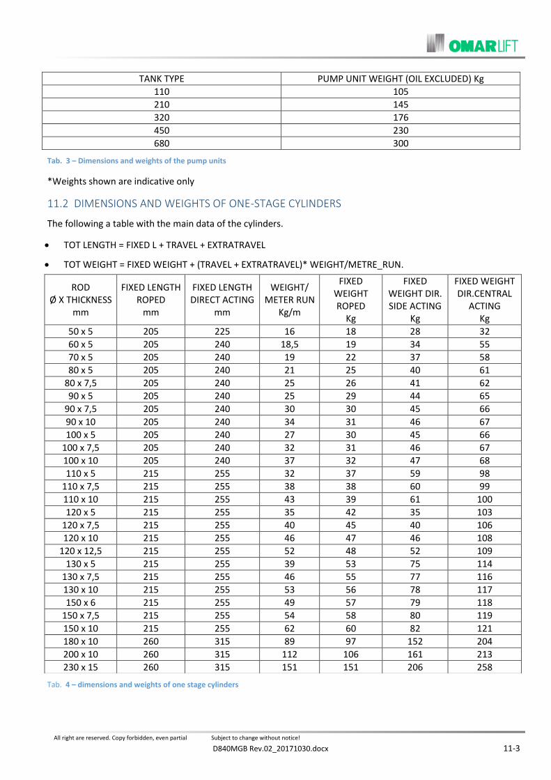
All right are reserved. Copy forbidden, even partial Subject to change without notice!
D840MGB Rev.02_20171030.docx 11-3
Tab. 3 – Dimensions and weights of the pump units
*Weights shown are indicative only
DIMENSIONS AND WEIGHTS OF ONE-STAGE CYLINDERS 11.2
The following a table with the main data of the cylinders.
TOT LENGTH = FIXED L + TRAVEL + EXTRATRAVEL
TOT WEIGHT = FIXED WEIGHT + (TRAVEL + EXTRATRAVEL)* WEIGHT/METRE_RUN.
Tab. 4 – dimensions and weights of one stage cylinders
TANK TYPE PUMP UNIT WEIGHT (OIL EXCLUDED) Kg
110 105
210 145
320 176
450 230
680 300
ROD Ø X THICKNESS
mm
FIXED LENGTH ROPED
mm
FIXED LENGTH DIRECT ACTING
mm
WEIGHT/ METER RUN
Kg/m
FIXED WEIGHT ROPED
Kg
FIXED WEIGHT DIR. SIDE ACTING
Kg
FIXED WEIGHT DIR.CENTRAL
ACTING Kg
50 x 5 205 225 16 18 28 32
60 x 5 205 240 18,5 19 34 55
70 x 5 205 240 19 22 37 58
80 x 5 205 240 21 25 40 61
80 x 7,5 205 240 25 26 41 62
90 x 5 205 240 25 29 44 65
90 x 7,5 205 240 30 30 45 66
90 x 10 205 240 34 31 46 67
100 x 5 205 240 27 30 45 66
100 x 7,5 205 240 32 31 46 67
100 x 10 205 240 37 32 47 68
110 x 5 215 255 32 37 59 98
110 x 7,5 215 255 38 38 60 99
110 x 10 215 255 43 39 61 100
120 x 5 215 255 35 42 35 103
120 x 7,5 215 255 40 45 40 106
120 x 10 215 255 46 47 46 108
120 x 12,5 215 255 52 48 52 109
130 x 5 215 255 39 53 75 114
130 x 7,5 215 255 46 55 77 116
130 x 10 215 255 53 56 78 117
150 x 6 215 255 49 57 79 118
150 x 7,5 215 255 54 58 80 119
150 x 10 215 255 62 60 82 121
180 x 10 260 315 89 97 152 204
200 x 10 260 315 112 106 161 213
230 x 15 260 315 151 151 206 258

All right are reserved. Copy forbidden, even partial Subject to change without notice!
11-4 D840MGB Rev.02_20171030.docx
DIMENSIONS AND WEIGHTS OF THE TELESCOPIC CYLINDERS, FILLING OIL AND OIL FOR 11.3
MOVEMENT
The encumbrance length of the telescopic cylinders is calculated dividing the total run of the cylinder per “K”
factor and adding value “XL” or “Xc” reported in the following table.
𝐿 = 𝑇𝑂𝑇𝐴𝐿 𝑅𝑈𝑁 (𝑚𝑚)
𝐾+ 𝑋 (𝑚𝑚) (𝑈𝑝𝑝𝑒𝑟 𝑝𝑙𝑎𝑡𝑒 𝑖𝑛𝑐𝑙𝑢𝑑𝑒𝑑)
XL = fix length for direct side acting cylinders;
Xc = fix length for direct central acting cylinders;
The cylinder weight is calculated by multiplying the cylinder run is metres per the weight/metre, plus the fix
weight. The fix weight of the telescopic cylinders is strongly influenced by some variants which depend on the run
of the cylinder itself.
- Presence or not of guide arms.
- Length of internal spacers for the synchronism.
- Different size of the rupture valve, etc.
NB: THE THEORETICAL WEIGHT DRAWN FROM THE TABLES CAN BE LIGHTLY DIFFERENT FROM THE REAL WEIGHT
OF THE TELESCOPIC CYLINDER.
TWO-STAGE TELESCOPIC CYLINDERS TYPE CT-2
ROD TYPE [mm]
CT - 2 - 40 40/55
CT - 2 - 50 50/70
CT - 2 - 63 63/85
CT - 2 - 70 70/100
CT - 2- 85 85/120
CT - 2 - 100 100/140
CT - 2 - 120 120/160
CT - 2 - 140 140/200
“K” FACTOR 1,95 1,93 1,98 1,90 1,998 1,93 1,99 1,90
“XL” DIR. SIDE ACTING MM 610 630 650 670 690 730 750 780
“Xc” DIR. CENTRAL ACTING MM 595 615 635 650 670 710 730 750
WEIGHT METER/RUN kg/m
15 22 30 43 62 71 76 106
FIX WEIGHT DIR. SIDE ACTING kg
80 110 140 190 270 300 370 450
FIX WEIGHT DIR CENTRAL ACTING kg
110 140 170 230 320 350 430 520
FILLING OIL l/m RUN 0,9 1,5 2,3 3 4,1 6 8,5 12,3
OIL FOR MOVEMENT l/m RUN 1,8 2,8 4,3 5,7 8,5 11,4 15,7 22,6
Tab. 5 – dimensions and weights – two stage telescopic cylinders type CT-2

All right are reserved. Copy forbidden, even partial Subject to change without notice!
D840MGB Rev.02_20171030.docx 11-5
THREE-STAGE TELESCOPIC CYLINDER TYPE CT-3
ROD TYPE [mm]
CT - 3 - 40 40/55/80
CT - 3 - 50 50/70/100
CT - 3 - 63 63/85/120
CT - 3 - 70 70/100/140
CT - 3 - 85 85/120/170
CT - 3 - 100 100/140/200
CT - 3- 120 120/160/230
“K” FACTOR 2,935 2,843 2,980 2,875 2,992 2,843 2,998
“XL” DIR. SIDE ACTING MM 700 765 810 830 850 920 950
“Xc” DIR. CENTRAL ACTING MM 685 750 795 810 825 895 920
WEIGHT METER/RUN kg/m
18 27 35 46 72 92 113
FIX WEIGHT DIRECT SIDE ACTING kg
140 160 230 260 310 480 530
FIX WEIGHT DIR. CENTRAL ACTING kg
180 200 270 315 370 550 620
FILLING OIL l/m RUN 2,0 3,0 4,7 6,2 9,2 11,9 16,3
OIL FOR MOVEMENT l/m RUN 2,9 4,4 6,7 9 13,3 17,7 23,6
Tab. 6 – dimensions and weights – three-stage telescopic cylinders type CT-3


All right are reserved. Copy forbidden, even partial Subject to change without notice!

All right are reserved. Copy forbidden, even partial Subject to change without notice!
OMARLIFT S.r.l. Via F.lli Kennedy 22/D I-24060 Bagnativa (BG) – ITALY Tel.+39 035 689611 Fax +39 035 689671 E-mail:[email protected] http://www.omarlift.eu