operating instructions for akkumaster c5 - h-tronic.com · operating instructions for akkumaster c5...
TRANSCRIPT

Operating instructions for AkkuMaster C5
Before using the unit, pay careful attention to the instructions in this operating manual. We are required by legislation to give you important advice regarding your safety and to draw your attention to how you can prevent causing harm to persons, damaging the unit and other equipment. If you fail to follow these instructions, the manufacturer will accept no liability for any damage resulting from negligent or deliberate disregard of the instructions in this operating manual!
Dangers handling the charger
The charger is constructed according to the latest state of the art and recognised technological safety guidelines. Nevertheless, incorrect operation or misuse can result in dangers
- to life and limb of the user or third parties, - to the charger and other material assets belonging to the user.
All persons involved in the commissioning, operation, servicing and maintenance of the charger must either be suitably qualified or either have or acquire knowledge about dealing with chargers and batteries and
- follow the operating instructions exactly. Faults which compromise safety are to be avoided and, if need be, to be corrected immediately.
In order to ensure hazard-free operation, the user must pay close attention to the safety advice and warning notices contained within these operating instructions. Intended use The unit is suitable for the automatic charging and buffering of lead-gel, lead-fleece or lead-acid batteries and NiCd, NiMH, Pb, Li-ion and Li-polymer batteries. No non-rechargeable batteries (zinc-carbon, alkaline, etc.), or other battery types are to be connected and charged. Any other use, other than as described, is not permissible and will cause damage to this product. Moreover, this is associated with dangers such as, e.g. short-circuiting, fire, electric shock etc. In order to prevent malfunctions, damages and dangers to health please pay attention to the following safety advice: * Please read through these operating instructions carefully and only use the charger in accordance with this operating manual. * Dispose of any unused packaging materials or store them in an area not accessible to children. There is a danger of suffocation! * In case of damage to the charger or the connection leads, these must not be used. You should have it repaired by a specialist. Before each use, carry out an inspection of the connection leads (mains cable, charging cable) for any damage. * When charging lead/acid batteries, explosive gases which are hazardous to health can be given off. Therefore, only charge the batteries in well-ventilated rooms. Avoid open fires and sparks. * Do not charge any other batteries other than those described in this operating manual. * Make sure that the ventilation slits are not covered. * The mains lead must only be connected to a 230 volt AC / 50 Hz (10/16A) earthed electrical socket. * Avoid charging old, damaged, very heavily discharged or faulty lead/acid batteries. * Do not charge dry-cell batteries under any circumstances. * Do not use the unit out in the open air. * The unit is not suitable for use by children. * Make sure that you are not wearing any conductive jewellery such as necklaces, bracelets or rings whilst using the charger. * Be careful not to come into contact with the battery acid. Battery acid can cause serious chemical burns! In case of contact, you should immediately wash the affected area with copious amounts of water and, if need be, seek medical attention. * During prolonged use at the maximum charge current the unit heats up.

Therefore, check the charging process at regular intervals and, in the event of any irregularities (excessive heating of the battery, strong liberation of gas), immediately pull out the mains plug and disconnect the battery from the charger. * When you are not using the charger or when you are cleaning it, pull out the mains plug and disconnect the unit from the battery. Never pull on the mains lead, instead grasp the mains plug. * Do not dismantle the charger and do not attempt to make any repairs. The charger contains no parts that can be replaced or repaired by you. * If the unit starts to smoke, gives off a burning smell or makes strange noises, immediately disconnect from the mains supply and seek advice from your specialist dealer.
In the event of any damages resulting from failure to follow these operating instructions the claim under guarantee is discharged. We accept no liability for consequential damages! In the event of property and personal damages resulting from improper handling or failure to follow safety advice, we accept no liability. In such cases any claim under guarantee is extinguished! The following safety and hazard advice serves not only to protect your health but also to protect the unit. Please read through the following points carefully:
• For reasons of safety and admissibility (CE) the unauthorised conversion and/ or alteration of the product is not permitted.
• For voltage/power supply, the charger must be connected via the mains cable to the public power supply using the correct mains plug (230V~/50Hz).
• The product must only be used in dry, closed interiors. It must not become damp or wet. Avoid direct sunlight, high heat, (>35°C) or cold (<0°C). The same applies to the connected battery.
• For example, do not place any containers, vases or plants on or next to this charger and the battery. Liquids could get into the casing and thereby compromise electrical safety. Moreover, there is a great danger of fire or a life-threatening electric shock!
In this case, immediately disconnect the product from the mains power supply (first switch the mains off at the socket, then pull the mains plug out of the mains socket!). Then disconnect the battery from the charger.
The battery must be dried completely or cleaned on the outside. Do not use the charger anymore; bring it to a specialist workshop.
• The product is not a toy. It is not suitable for children. Be particularly vigilant when children are present! Children may attempt to stick objects through the openings in the casing. This causes damage to the unit and, furthermore, there is danger to life through electric shock!
The product must only be set up, operated or stored in a place where it is not accessible to children. Children could alter settings or short-circuit the battery/battery pack, which can cause an explosion. Mortal danger!
• Do not leave the packaging material lying around unattended. This could become a dangerous toy for children!
• The product is only suitable for charging lead-acid, lead-gel, NiCd, NiMH, Pb, Li-ion and Li-polymer batteries.
• Pay close attention to the battery manufacturer’s specifications.
• Non-rechargeable batteries must not be charged! Danger of explosion!
• Never operate the product unattended. Despite the comprehensive and multiple safety switches, malfunctions or problems cannot be excluded during battery charging.
• Only operate the product in a moderate climate, never in a tropical climate. Pay attention to the chapter ‘Technical data' for permissible environmental conditions.
4. Safety advice

• Select a stable, sufficiently large and flat surface location. Otherwise, there is a danger of injury due to the weight of the product should it fall off. Moreover, the unit will be damaged.
Never place the charger and battery on inflammable surfaces (e.g. carpets). Make sure that no easily inflammable items (cloths, cotton waste or similar) are next to the unit. Also ensure that the mains and charging leads are on non-flammable surfaces and not next to easily inflammable items or surfaces. If necessary, use a suitable non-flammable base (e.g. a large, thick porcelain tile or stone slab).
• Ensure sufficient ventilation during the operation phase; never cover the charger or the connected battery. Leave a sufficient gap (min. 5-10cm) between the charger and surroundings/wall to enable adequate air circulation.
• Never connect the product to the mains supply immediately after it has been brought from a cold room into a warm room. Under certain circumstances the resultant condensation can lead to malfunction or damages and, moreover, there is a danger of electric shock.
First allow the charger (and the battery/batteries) to equilibrate to room temperature prior to connecting the charger to the mains supply and operating it. This can take several hours!
• Service, adjustment or repair work may only be carried out by specialists/specialist workshops. There are no product parts within the unit which may be serviced or adjusted by you.
• In commercial establishments the accident prevention regulations of the Health and Safety Executive (HSE) are to be observed.
• In schools, educational establishments, hobby and self-help workshops the operation of this product is to be overseen by trained personnel.
• Handle the product carefully; it will be damaged by blows, knocks or a fall from even a short height. Should you not be entirely clear about the correct connection or operation, or should any questions arise, the answers to which are not covered by the operating instructions, then please contact our technical information office or another specialist.
• Operation is only permissible in dry, closed interiors. The charger (and a connected battery/battery pack) must not be allowed to become damp or wet.
• Place the charger on an even, solid and non-flammable surface. This must be large enough so that the connected battery/battery pack can be placed safely alongside it.
The battery must not be placed on top or under the charger!
Although the charger is equipped with numerous safety functions, excessive heating of the battery can never be completely excluded. The use of charging cables which are too thin or connection problems which occur, can also lead to dangerous operating conditions.
Do not place the charger on valuable furniture surfaces (not even for storage when not in use); chemical reactions can otherwise cause discolouration due to the rubber feet, moreover, impressions may result. Use a suitable base.
• Pay attention when setting up the charger that neither the mains cable nor the battery charging cable becomes bent or squashed. Place the charger, battery and cables in such a way that no one can trip over them.
• Never operate the charger unattended!
• Avoid the following adverse environmental conditions at the site of operation or during transport: Strong or direct sunlight
Wetness or too high a humidity Extreme cold (<0°C) or heat (>35°C) Dust or inflammable gases, steam or solvents, strong vibrations, strong magnetic fields (such as occur near machines or loudspeakers)
Handling

• Ensure that the entire product’s insulation is neither damaged nor destroyed. Never open or dismantle it!
• Inspect the product for any damage prior to each use! Should you find any damage, do not operate the unit but take it to a specialist workshop.
• When the unit is not in use, disconnect it from the mains supply and the battery.
• Never touch the unit through its ventilation slits or other openings in the unit with sharp objects (e.g. ball point pen, sewing and knitting needles, paper clips etc.). There is a danger of lethal electric shock and damage to the unit!
6. Cleaning In order to clean the casing use a soft cloth and some mild detergent. Strong solvents such as thinners or petrol as well as scouring agents must not be used, as they react with the surface. Dispose of cleaning cloths and surplus cleaning agents in an environmentally friendly manner. For safety reasons, the mains plug must always be pulled out before cleaning! Prevent cleaning agents from getting inside the unit! Electromagnetic compatibility This item has been tested according to EC Directive 89/336/EEC (EMC from 09.11.1992, electromagnetic compatibility) and meets the legal requirements.
Overview of the most important specifications: • Battery types NiCd, NiMH, Pb, Li-ion, Li-polymer
• Charging/discharge current(min) 50 mA
• Charging/discharge current(max) 5000 mA
• Cell number (NiCd, NiMH) 1 - 20 cells
• Cell number (Pb) 1 - 14 cells
• Cell number (Li-ion, Li-polymer) 1 - 8 cells
• Battery capacity 100 mAh - 100 Ah
• Operating voltage 230 V/50 Hz
• Power consumption max. 80 VA
• Maximum output voltage: 38V;
• Maximum charging rate: 70W;
• Maximum discharge rate: 30W;
Overview of the most significant features: • Simple and intuitive menu control using a joystick
• Six general service programmes: o Charging; o Discharging; o Discharging-Charging; o Charging-Discharging-C; o Cycle; o Forming;
• A special charging programme that enables the charging voltage and charge current to be set by hand (manual charging).
• Integrated data logger for recording charge/discharge curve progress without a PC
• Fine settings for parameters such as: o Delta peak o Charging cut-off voltage o Discharging cut-off voltage o Switch-off current o Maximum battery temperature o Etc.
• Temperature control of the battery with a temperature sensor
• USB port for: o Firmware update; o Data logger flash readout; o Data transfer to PC; o Remote control of the unit, with the possibility to develop one’s own
charge/discharge programmes, independent of unit programmes.
• UART-TTL port for remote control of the unit through a microcontroller
• Display of various set and determined parameters during the service process, as well as the resistance of the current-chain ‘battery+charging cable’ and charge/discharge statistics.
• Temperature controlled cooling fan

• Data preservation in case of mains power failure, automatic restart of the interrupted programme

1. The menu structure

1.1 Menu layout
In order to control the menu a joystick is used on the unit, which may be thought of as a combination of five keys: ‘Up’, ‘Down’, ‘Right’, ‘Left’, ‘Enter’.
Each menu item consists of a whole screen where the name of the menu item, the value of the menu item (if available) and the navigation symbols are displayed. The navigation symbols indicate which keys are available in that particular menu. An active menu item contains an ‘enter’ symbol. This indicates that this menu item may be edited, confirmed or executed.
Hint: First and foremost the menu description is meant for getting to know the menu structure.
All menu items, that are described further in the operating manual, apply to firmware version
1.0. The right to make possible changes to names, terminology, settings ranges etc. in new
versions is reserved.
1.2 ‘Accu service’ menu The menu ‘Accu service’ contains six general service programmes:
o Charge; o Discharge; o Discharge-Charge; o Charge-Discharge-Charge; o Cycle; o Forming;
In order to describe a typical menu layout we will take the menu programme ‘Cycle’, because
this programme contains all the possible settings which the other programmes can have. The settings for the programme:
01.
02. + ‘Enter’ 02.1.
03. 04. 05.
06. 07. 08.
09. 10. 11.
12. Figure no. 1
The ‘Accu service’ menu item. The ‘Accu choice’ menu item is selected using the ‘Right’ key.
Figure no. 2
The ‘Accu choice’ menu item. In this menu item the storage place for a battery configuration is selected. This is done by pressing the ‘Enter’ key. Now you can select the desired place using the ‘UP/DOWN’ keys (Figure 2.1). In order to confirm your selection press the ‘Enter’ key again. Settings range: 1 - 20;
Figure no. 3
The 'Accu program’ menu item. In this menu item the desired service programme is selected. In our case: ‘Cycle’. Settings range:
Navigation symbols

• Charge
• Discharge
• Discharge-Charge
• Charge-Discharge-Charge
• Cycle
• Forming Figure no. 4
The ‘Accu type’ menu item. In this menu item the desired battery type is selected. In our case: ‘NiMH’. Settings range:
• NiCd
• NiMH
• Pb
• Li-ion
• Li-polymer Figure no. 5
The ‘Cell count’ menu item. In this menu item the connected battery’s cell count is entered. If the ‘Up’ or ‘Down’ key is pressed and held, the values in the display will change more quickly. In the display, the nominal voltage of the connected cells is given after the cell count of the connected cells. Settings range:
The maximum possible value is calculated according to the following formula: Cell count max. = U out max./U cell max. here:
Cell count max.: maximum possible cell count; U out max.: maximum possible output voltage for the charger( 38V ); U cell max.: maximum possible cell voltage;
Figure no. 6
The ‘Accu capacity’ menu item. In this menu item the battery capacity of the connected battery is entered. If the ‘Up’ or ‘Down’ key is pressed and held, the values in the display will change more quickly. From the capacity entry the AkkuMaster calculates different charge/discharge parameters; e.g. the percentage, the charge/discharge current standard values etc. Settings range: 100mAh - 100000mAh;
Figure no. 7
The ‘Charge cur.’ menu item. The AkkuMaster suggests a standard value for the charge current for the currently connected battery type. The suggested values can be revised and altered. Settings range: 50mA to 5000mA; Hint: The settings range is automatically reduced, if the maximum charging rate is exceeded.
Figure no. 8
The ‘Disch. cur.’ menu item. The AkkuMaster suggests a standard value for the discharge current for the currently connected battery type. The suggested values can be revised and altered. Settings range: 50mA to 5000mA; Hint: The settings range is automatically reduced, if the maximum discharge rate is exceeded.
Figure no. 9
The ‘Service pause’ menu item. Each service programme (except ‘Charge’ and ‘Discharge’) consists of a combination of charge and discharge procedures. The service pause (SP) is a pause that is entered between discharge and charge or charge and discharge procedures. E.g. for the service programme:
• Discharge-Charge: Discharge – SP – Charge;
• Charge-Discharge-Charge: Charge – SP - Discharge – SP – Charge; Here: SP = service pause;
Settings range: 1 - 60min; Figure no. 10
The ‘Cycle pause’ menu item. The ‘Cycle’ and ‘Forming’ programmes consist of a discharge-charge procedure which is performed in a cyclical manner. The cycle pause (CP) is a pause which is entered between cycles. E.g.:
• (Discharge – SP – Charge) – CP – (Discharge – SP – Charge) – CP - ...; Here: SP – Service pause; CP – Cycle pause;
Settings range: 1 min to 30 Days; Figure no. 11
The ‘Cycles’ menu item. In this menu item the number of cycles is entered. Settings range: 1 to 20;
Figure no. 12
The ‘Start’ menu item. In this menu item the selected service programme is executed following confirmation by pressing the ‘Enter’ key. The configuration data are thereby stored.
During the programme the following programme states are displayed:
1.2.1 Discharge procedure

01. 02. 03.
04. 05. 06.
07. 08. 09.
10. 11. 12.
13. Figure no. 1
The ‘Status’ menu item. In this menu item the programme status is displayed. Figure no. 2
The ‘Setting info’ menu item. In this menu item the settings made are displayed. Using the ‘Left/Right’ keys all data can be browsed through.
Figure no. 3
The ‘Cycle’ menu item. In this menu item the number of the running discharge-charge procedure is displayed.
Figure no. 4
The ‘Total time’ menu item. In this menu item the total elapsed programme time is displayed. The time format is: DDD HH:MM:SS. Here:
o DDD: Days; o HH: Hours; o MM: Minutes; o SS: Seconds;
Figure no. 5
The ‘Discharge time’ menu item. In this menu item the elapsed discharge time is displayed.
Figure no. 6
The ‘D/C history’ menu item. In this menu item the discharge/charge statistics are displayed.
Here: ‘D’= The discharge capacity in this discharge-charge procedure as a percentage of
the rated capacity. ‘C’= The charge capacity in this charge-discharge procedure as a percentage of
the rated capacity. The procedure number is given in brackets at the top. In this case: If the other procedures are available at this moment, then it is possible to browse through these menu items using the ‘Right/Left’ keys (Figures 4.1 and 4.2).
04.1 04.2 Figure no. 7
The ‘Discharged’ menu item. In this menu item the running discharge capacity is displayed.
Figure no. 8
The ‘U input’ menu item. In this menu item the input voltage (discharge current switched ‘on’ on the unit) is displayed.
Figure no. 9
The ‘U accu’ menu item. In this menu item the battery voltage (discharge current switched off, i.e. no current) is displayed.
Figure no. 10
The ‘Discharge current’ menu item. In this menu item the measured discharge current is displayed.
Figure no. 11
The ‘R(accu+cable)’menu item. In this menu item the ascertained resistance of the current-chain ‘battery + contacts + charge cable“ is displayed. This is a very important parameter which can say a lot about the condition of the battery. With a good charge cable (adequate cross-section) and clean contacts (little resistance across contacts) this value should lie below 1 Ohm. Higher values indicate that the battery is old or has been stored for too long, is defective, sulphated etc.
Figure no. 12
The ‘T accu’ menu item. In this menu item the measured battery temperature is displayed (if the temperature sensor is present).
Figure no. 13
The ‘Exit’ menu item. In this menu item (as well as in others) the programme can be aborted if the ‘Enter’ key is pressed and exit is confirmed thereafter.

1.2.2 Service pause
01. 02. 03.
04. 05. 06.
07. 08. 09. Figure no. 1
The ‘Status’ menu item. In this menu item the programme status is displayed. Figure no. 2
The ‘Setting info’ menu item. In this menu item the settings which are made are displayed. Using the ‘Left/Right’ keys all data can be browsed through.
Figure no. 3
The ‘Cycle’ menu item. In this menu item the number of the running discharge-charge procedure is displayed.
Figure no. 4
The ‘Total time’ menu item. In this menu item to total elapsed programme time is displayed.
Figure no. 5
The ‘D/C history’ menu item. In this menu item the discharge-charge statistics are displayed.
Figure no. 6
The ‘Pause time’ menu item. In this menu item the elapsed pause time is displayed. Figure no. 7
The ‘Remain time’ menu item. In this menu item the remaining pause time is displayed. Figure no. 8
The ‘U accu’ menu item. In this menu item the battery voltage is displayed. Figure no. 9
The ‘Exit’ menu item. In this menu item (as well as in others) the programme can be aborted if the ‘Enter’ key is pressed and exit is confirmed thereafter.
1.2.3 Charging procedure
01. 02. 03.
04. 05. 06.
07. 08. 09.
10. 11. 12.
13. Figure no. 1
The ‘Status’ menu item. In this menu item the programme status is displayed. Figure no. 2
The ‘Setting info’ menu item. In this menu item the settings which are made are displayed. Using the ‘Left/Right’ keys all data can be browsed through.
Figure no. 3
The ‘Cycle’ menu item. In this menu item the number of the running discharge-charge procedure is displayed.
Figure no. 4
The ‘Total time’ menu item. In this menu item to total elapsed programme time is displayed.
Figure no. 5
The ‘Charge time’ menu item. In this menu item the elapsed charge time is displayed. Figure no. 6
The ‘D/C history’ menu item. In this menu item the discharge-charge statistics are displayed.
Figure no. 7
The ‘Charged’ menu item. In this menu item the current capacity charged is displayed. Figure no. 8
The ‘U charge’ menu item. In this menu item the output voltage (charge current switched ‘on’ on the unit) is displayed.

Figure no. 9
The ‘U accu’ menu item. In this menu item the battery voltage (charge current switched off, i.e. no current) is displayed.
Figure no. 10
The ‘Charge current’ menu item. In this menu item the measured charge current is displayed.
Figure no. 11
The ‘R(accu+cable)’menu item. In this menu item the ascertained resistance of the current-chain ‘battery + contacts + charge cable“ is displayed. This is a very important parameter which can say a lot about the condition of the battery. With a good charge cable and clean contacts, this value should lie below 1 Ohm. Higher values indicate that the battery is old or has been stored for too long, is defective, sulphated etc.
Figure no. 12
The ‘T accu’ menu item. In this menu item the measured battery temperature is displayed (if the temperature sensor is present).
Figure no. 13
The ‘Exit’ menu item. In this menu item (as well as in others) the programme can be aborted if the ‘Enter’ key is pressed and exit is confirmed thereafter.
1.2.4 Cycle pause
01. 02. 03.
04. 05. 06.
07. 08. 09. Figure no. 1
The ‘Status’ menu item. In this menu item the programme status is displayed. Figure no. 2
The ‘Setting info’ menu item. In this menu item the settings which are made are displayed. Using the ‘Left/Right’ keys all data can be browsed through.
Figure no. 3
The ‘Cycle’ menu item. In this menu item the number of the running discharge-charge procedure is displayed.
Figure no. 4
The ‘Total time’ menu item. In this menu item to total elapsed programme time is displayed.
Figure no. 5
The ‘D/C history’ menu item. In this menu item the discharge-charge statistics are displayed.
Figure no. 6
The ‘Pause time’ menu item. In this menu item the elapsed pause time is displayed. Figure no. 7
The ‘Remain time’ menu item. In this menu item the remaining pause time is displayed. Figure no. 8
The menu item „U accu“. In this menu item the battery voltage is displayed. Figure no. 9
The ‘Exit’ menu item. In this menu item (as well as in others) the programme can be aborted if the ‘Enter’ key is pressed and exit is confirmed thereafter.
1.2.4 Ready
When all 5 preset cycles have elapsed, the ‘Cycle’ service programme is terminated. The following data are displayed as the results:
01.
02.
03.
04.1 04.2 04.3
04.4 04.5
05. 06. Figure no. 1
The ‘Status’ menu item. In this menu item the programme status is displayed. Figure no. 2
The ‘Setting info’ menu item. In this menu item the settings which are made are displayed. Using the ‘Left/Right’ keys all data can be browsed through.
Figure no. 3
The ‘Total time’ menu item. In this menu item the total programme time is displayed. Figure no. 4.1 to no. 4.5
The ‘D/C history’ menu item. In this menu item the charge-discharge statistics are displayed.
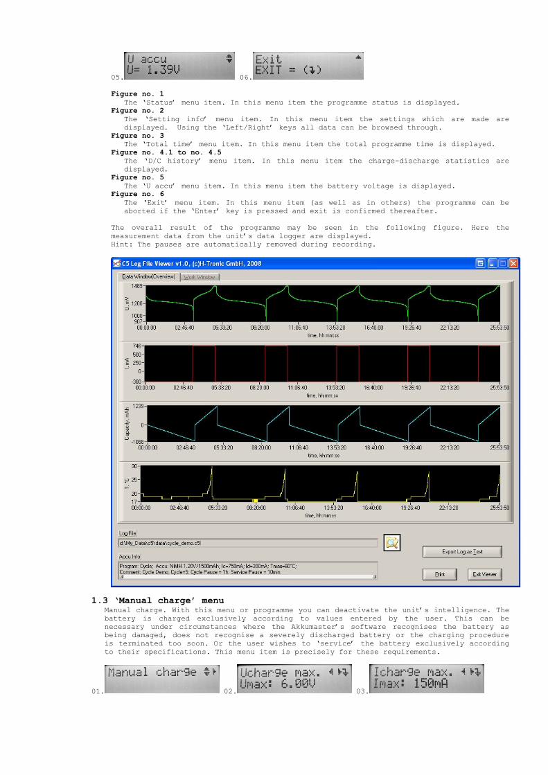
Figure no. 5
The ‘U accu’ menu item. In this menu item the battery voltage is displayed. Figure no. 6
The ‘Exit’ menu item. In this menu item (as well as in others) the programme can be aborted if the ‘Enter’ key is pressed and exit is confirmed thereafter.
The overall result of the programme may be seen in the following figure. Here the measurement data from the unit’s data logger are displayed. Hint: The pauses are automatically removed during recording.
1.3 ‘Manual charge’ menu Manual charge. With this menu or programme you can deactivate the unit’s intelligence. The battery is charged exclusively according to values entered by the user. This can be necessary under circumstances where the Akkumaster’s software recognises the battery as being damaged, does not recognise a severely discharged battery or the charging procedure is terminated too soon. Or the user wishes to ‘service’ the battery exclusively according to their specifications. This menu item is precisely for these requirements.
01. 02. 03.

04. 05. 06. Figure no. 1
The ‘Manual charge’ menu item. Figure no. 2
The ‘Ucharge max.’ menu item. In this menu item the maximum charge voltage is set. Settings range: 1V to 38V; Hint: The settings range is automatically reduced, if the maximum charge rate is exceeded.
Figure no. 3
The ‘Icharge max.’ menu item. In this menu item the maximum charge current is set. Settings range: 50mA to 5000mA; Hint: The settings range is automatically reduced, if the maximum charge rate is exceeded.
Figure no. 4
The ‘Charge time’ menu item. In this menu item the charge time is set. Settings range: 1 min to 24 hours;
Figure no. 5
The ‘T accu max.’ menu item. In this menu item the maximum allowable battery temperature is set. Settings range: 30 - 70°C;
Figure no. 6
The ‘Start’ menu item. In this menu the programme is executed following confirmation by pressing the ‘Enter’ key. The configuration data are thereby stored. The charging procedure is terminated if the set charge time has elapsed or the set battery temperature has been exceeded.
1.3.1 Some charging examples for various battery types Note: The strength of charge and discharge currents is indicated as a multiple of a battery’s capacity rating. The designation for this is ‘C’ or ‘CA’. Example no. 1
Battery: NiCd/NiMH, 1.2V/1500mAh; charging method: standard charge with 1/10C charge current and time limit; Settings:
1. Charge voltage (Umax): Uaccu(max. value) + potential voltage drop between battery and charger => 1.9V + 4V = 5.9V => Umax = 6V;
2. Charge current (Imax): 1/10C -> 150mA; 3. Charge time: 16 hours(time limit: max. 160% of capacity rating is charged); 4. Battery temperature: 40°C; the temperature setting is considered if the
temperature sensor is connected.
Example no. 2 Battery: NiCd/NiMH, 1.2V/1500mAh; charging method: standard charge with 1/10C charge current and battery voltage and time limit; Settings:
1. Charge voltage (Umax): Umax = 1.5V; 2. Charge current (Imax): 1/10C -> 150mA; 3. Charge time: 16 hours (time limit: max. 160% of capacity rating is charged); 4. Battery temperature: 40°C; the temperature setting is considered if the
temperature sensor is connected.
Example no. 3 Battery: NiCd/NiMH, 1.2V/1500mAh; charging method: quick charge with temperature switch-off and time limit; Settings:
1. Charge voltage (Umax): Uaccu (max. value) + potential voltage drop between battery and charger => 1.9V + 4V = 5.9V => Umax = 6V;
2. Charge current(Imax): 1C -> 1500mA; 3. Charge time: 1.6 hours (time limit: max. 160% of capacity rating is charged); 4. Battery temperature: 40°C; the temperature setting is considered if the
temperature sensor is connected. Example no. 4
Battery: Pb, 12V/10Ah; charging method: standard charge with 1/10C charge current and time limit; Settings:
1. Charge voltage(Umax): Umax = 14.3V(charge cut-off voltage); 2. Charge current(Imax): 1/10C -> 1000mA; 3. Charge time: 16 hours (time limit: max. 160% of capacity rating is charged); 4. Battery temperature: 40°C; the temperature setting is considered if the
temperature sensor is connected.
Example no. 5 Battery: Pb, 12V/10Ah; charging method: standard charge with 1/10C charge current and time limit; Settings:

1. Charge voltage (Umax): Umax = cells x Umax/cell = 6 x 2.38 = 14.3V (charge cut-off voltage);
2. Charge current (Imax): 1/10C -> 1000mA; 3. Charge time: 16 hours(time limit: max. 160% of capacity rating is charged); 4. Battery temperature: 40°C; the temperature setting is considered if the
temperature sensor is connected.
Example no. 6 Battery: Pb, 12V/10Ah; charging method: quick charge with 1/2C charge current and time limit; Settings:
1. Charge voltage(Umax): Umax = Cells x Umax/cell = 6 x 2.38V = 14.3V (charge cut-off voltage);
2. Charge current(Imax): 1/2C -> 5000mA; in this case the maximum charging rate is exceeded: P charge.max = 14.3V x 5A = 71.5W is greater than 70W. The unit will automatically limit the entered value to the maximum possible value of 4890mA.
3. Charge time: 3.3 hours(time limit: max. 160% of capacity rating is charged); 4. Battery temperature: 40°C; the temperature setting is considered if the
temperature sensor is connected.
Example no. 7 Battery: Li-ion, 3.6V/1000mAh; charging method: standard charge with 1/10C charge current and time limit; Settings:
1. Charge voltage(Umax): Umax = cells x Umax/cell = 1 x 4.1V = 4.1V (charge cut-off voltage);
2. Charge current(Imax): 1/10C -> 100mA; 3. Charge time: 16 hours (time limit: max. 160% of capacity rating is charged); 4. Battery temperature: 40°C; the temperature setting is considered if the
temperature sensor is connected.
Example no. 8 Battery: Li-ion, 3.6V/1000mAh; charging method: quick charge with 1/2C charge current and time limit; Settings:
1. Charge voltage(Umax): Umax = cells x Umax/cell = 1 x 4.1V = 4.1V (charge cut-off voltage);
2. Charge current(Imax): 1/2C -> 500mA; 3. Charge time: 3.2 hours (time limit: max. 160% of capacity rating is charged); 4. Battery temperature: 40°C; the temperature setting is considered if the
temperature sensor is connected.
Example no. 9 Battery: Li-polymer, 3.7V/1000mAh; charging method: standard charge with 1/10C charge current and time limit; Settings:
1. Charge voltage(Umax): Umax = cells x Umax/cell = 1 x 4.2V = 4.2V (charge cut-off voltage);
2. Charge current(Imax): 1/10C -> 100mA; 3. Charge time: 16 hours (time limit: max. 160% of capacity rating is charged); 4. Battery temperature: 40°C; the temperature setting is considered if the
temperature sensor is connected.
Example no. 10 Battery: Li-polymer, 3.7V/1000mAh; charging method: quick charge with 1/2C charge current and time limit; Settings:
1. Charge voltage (Umax): Umax = cells x U cell max. = 1 x 4.2V = 4.2V (charge cut-off voltage);
2. Charge current (Imax): 1/2C -> 500mA; 3. Charge time: 3.2 hours(time limit: max. 160% of capacity rating is charged); 4. Battery temperature: 40°C; the temperature setting is considered if the
temperature sensor is connected.
During charging the following data are displayed (the settings from Example no. 3 will be used from now on):
01.
02.
02.1 02.2
02.3 02.4
03.
04.
05.
06.
07.
08.
09.
10.
11.
Figure no. 1
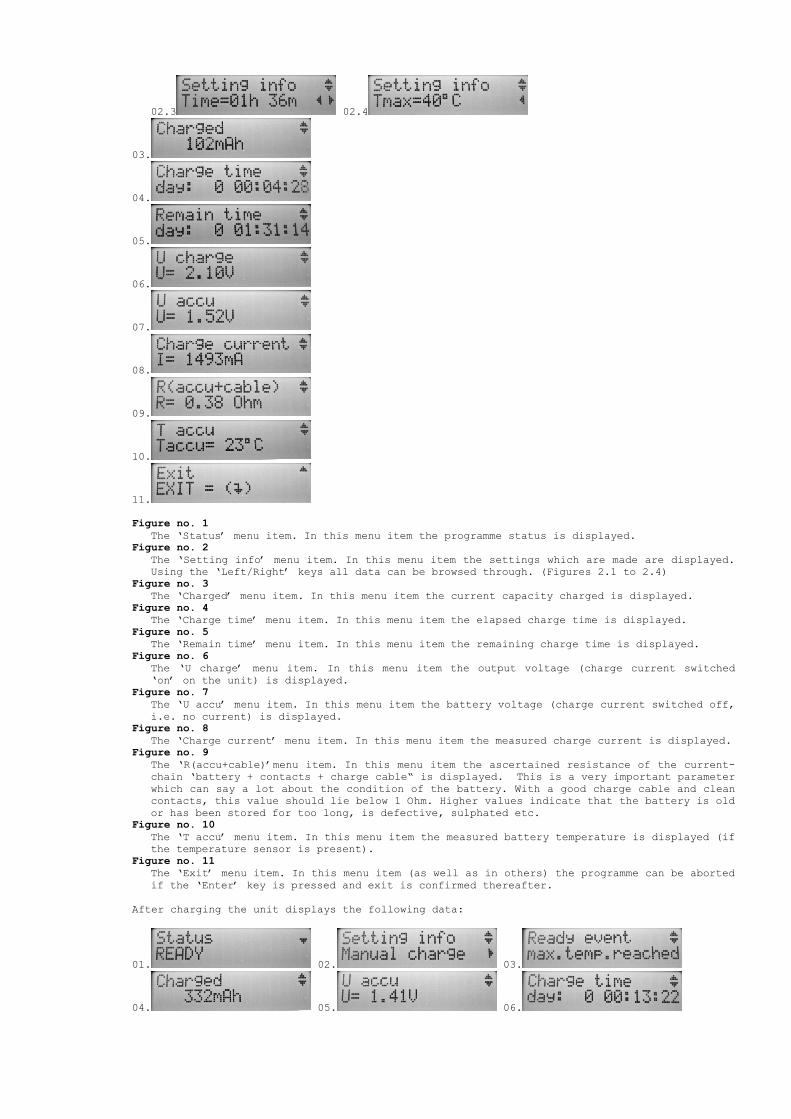
The ‘Status’ menu item. In this menu item the programme status is displayed. Figure no. 2
The ‘Setting info’ menu item. In this menu item the settings which are made are displayed. Using the ‘Left/Right’ keys all data can be browsed through. (Figures 2.1 to 2.4)
Figure no. 3
The ‘Charged’ menu item. In this menu item the current capacity charged is displayed. Figure no. 4
The ‘Charge time’ menu item. In this menu item the elapsed charge time is displayed. Figure no. 5
The ‘Remain time’ menu item. In this menu item the remaining charge time is displayed. Figure no. 6
The ‘U charge’ menu item. In this menu item the output voltage (charge current switched ‘on’ on the unit) is displayed.
Figure no. 7
The ‘U accu’ menu item. In this menu item the battery voltage (charge current switched off, i.e. no current) is displayed.
Figure no. 8
The ‘Charge current’ menu item. In this menu item the measured charge current is displayed. Figure no. 9
The ‘R(accu+cable)’menu item. In this menu item the ascertained resistance of the current-chain ‘battery + contacts + charge cable“ is displayed. This is a very important parameter which can say a lot about the condition of the battery. With a good charge cable and clean contacts, this value should lie below 1 Ohm. Higher values indicate that the battery is old or has been stored for too long, is defective, sulphated etc.
Figure no. 10
The ‘T accu’ menu item. In this menu item the measured battery temperature is displayed (if the temperature sensor is present).
Figure no. 11
The ‘Exit’ menu item. In this menu item (as well as in others) the programme can be aborted if the ‘Enter’ key is pressed and exit is confirmed thereafter.
After charging the unit displays the following data:
01. 02. 03.
04. 05. 06.

07. The overall result of the charging procedure can be seen in the following figure. Here the measurement data from the unit’s data logger are displayed.
Figure no. 1
The ‘Status’ menu item. In this menu item the programme status is displayed. Figure no. 2
The ‘Setting info’ menu item. In this menu item the settings which are made are displayed. Using the ‘Left/Right’ keys all data can be browsed through.
Figure no. 3
The ‘Ready event’ menu item. In this menu item the reason why the unit has terminated the charging procedure is displayed. For the ‘Manual Charge’ charging programme, it can either be the time (‘max. time reached’) or the temperature (‘max. temp. reached’).
Figure no. 4
The ‘Charged’ menu item. In this menu item the capacity charged is displayed. Figure no. 5
The ‘U accu’ menu item. In this menu item the actual battery voltage is displayed. Figure no. 6
The ‘Charge time’ menu item. In this menu item the elapsed charge time is displayed. Figure no. 7
The ‘Exit’ menu item. In this menu item (as well as in others) the programme can be aborted if the ‘Enter’ key is pressed.
Hint: Following charging with the ‘Manual Charge’ programme no charge conservation is performed.
1.4 ‘Settings’ menu This menu contains three submenus: ‘Accu config’, ‘Interface’ and ‘Calibrate’.
1.4.1 ‘Accu config’ menu In the ‘Accu config’ menu the following settings can be made: General settings:

01. 02. 03. Figure no. 1
The ‘Set default’ menu item. In this menu item the factory settings for the selected battery type can be restored.
Figure no. 2
The ‘Restore all’ menu item. In this menu item the factory settings for all battery types can be restored.
Figure no. 3
The ‘T accu max.’ menu item. In this menu item the maximum allowable battery temperature for the selected battery type is set. Settings range: 30 - 60°C; Factory setting: 40°C;
‘Delta peak(-dU)’ parameter and its meaning
When charging NiCd/NiMH batteries the battery voltage is constantly measured and the maximum value stored. If the battery is fully charged, this voltage no longer increases, but drops again very slightly. This voltage drop-off (-dU) is detected and the charging procedure is terminated. This switch-off, however, only functions reliably with a high charge current (from 1/2 C). ‘Charge factor’ parameter and its meaning
All charging programmes that come with the AkkuMaster have a built-in charge capacity limit. This charge capacity limit protects the battery from overloading (or from erroneous settings), if no other switch-off criteria take effect. The ‘charge factor’ of 1.6 is thereby taken into consideration. This means that the battery can be charged to a maximum of 160% of its capacity rating. Then the charging process is terminated. For NiCd/NiMH batteries there is a means of changing this charge factor. Settings for NiCd:
01. 02. 03.
04. Figure no. 1
The ‘U cell min.’ menu item. In this menu item the discharge cut-off voltage (per cell) is set. Settings range: 800 - 1100mV; Factory setting: 900mV;
Figure no. 2
The ‘U cell max.’ menu item. In this menu item the maximum allowable cell voltage is set. Settings range: 1500 - 2500mV; Factory setting: 1900mV;
Figure no. 3
The ‘deltaU’ menu item. In this menu item the settings (per cell) for the ‘Delta peak’ switch-off are carried out. Settings range: 1 - 50mV; Factory setting: 15mV;
Figure no. 4
The ‘Charge factor’ menu item. In this menu item the maximum allowable charge capacity as a percentage of capacity rating is set. Settings range: 100% - 160%; Factory setting: 140%;
Settings for NiMH:
01. 02. 03.
04. Figure no. 1
The ‘U cell min.’ menu item. In this menu item the discharge cut-off voltage (per cell) is set. Settings range: 800 - 1100mV; Factory setting: 900mV;
Figure no. 2
The ‘U cell max.’ menu item. In this menu item the maximum allowable cell voltage is set. Settings range: 1500 - 2500mV; Factory setting: 1900mV;
Figure no. 3
The ‘deltaU’ menu item. In this menu item the settings (per cell) for the ‘Delta peak’ switch-off are carried out. Settings range: 1 - 50mV; Factory setting: 5mV;
Figure no. 4
The ‘Charge factor’ menu item. In this menu item the maximum allowable charge capacity as a percentage of capacity rating is set. Settings range: 100% - 160%; Factory setting: 140%;
I cut-off parameter and its meaning
The ideal charging procedure for Pb, Li-ion and Li-polymer batteries is charging with IU characteristics. The battery is first charged with a constant current until the charge cut-off voltage is reached. Then the voltage is held constant and the charge current adapts to the battery’s charge state. The fuller the battery the lower the charge current. If a charge current falls short by a particular value (I cut-off), the charging procedure is deemed to have ended. Settings for Pb:
01. 02. 03. Figure no. 1
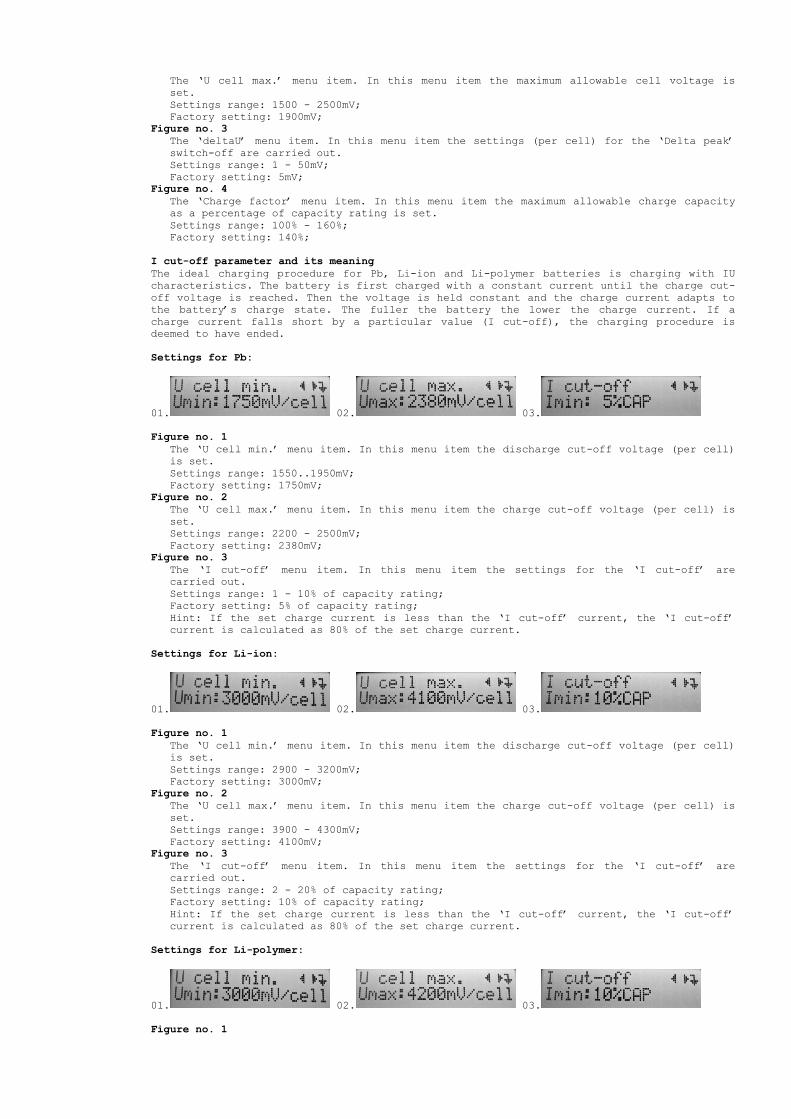
The ‘U cell min.’ menu item. In this menu item the discharge cut-off voltage (per cell) is set. Settings range: 1550..1950mV; Factory setting: 1750mV;
Figure no. 2
The ‘U cell max.’ menu item. In this menu item the charge cut-off voltage (per cell) is set. Settings range: 2200 - 2500mV; Factory setting: 2380mV;
Figure no. 3
The ‘I cut-off’ menu item. In this menu item the settings for the ‘I cut-off’ are carried out. Settings range: 1 - 10% of capacity rating; Factory setting: 5% of capacity rating; Hint: If the set charge current is less than the ‘I cut-off’ current, the ‘I cut-off’ current is calculated as 80% of the set charge current.
Settings for Li-ion:
01. 02. 03. Figure no. 1
The ‘U cell min.’ menu item. In this menu item the discharge cut-off voltage (per cell) is set. Settings range: 2900 - 3200mV; Factory setting: 3000mV;
Figure no. 2
The ‘U cell max.’ menu item. In this menu item the charge cut-off voltage (per cell) is set. Settings range: 3900 - 4300mV; Factory setting: 4100mV;
Figure no. 3
The ‘I cut-off’ menu item. In this menu item the settings for the ‘I cut-off’ are carried out. Settings range: 2 - 20% of capacity rating; Factory setting: 10% of capacity rating; Hint: If the set charge current is less than the ‘I cut-off’ current, the ‘I cut-off’ current is calculated as 80% of the set charge current.
Settings for Li-polymer:
01. 02. 03. Figure no. 1
The ‘U cell min.’ menu item. In this menu item the discharge cut-off voltage (per cell) is set. Settings range: 2900 - 3200mV; Factory setting: 3000mV;
Figure no. 2
The ‘U cell max.’ menu item. In this menu item the charge cut-off voltage (per cell) is set. Settings range: 4000 - 4400mV; Factory setting: 4200mV;
Figure no. 3
The ‘I cut-off’ menu item. In this menu item the settings for the ‘I cut-off’ are carried out. Settings range: 2 - 20% of capacity rating; Factory setting: 10% of capacity rating; Hint: If the set charge current is less than the ‘I cut-off’ current, the ‘I cut-off’ current is calculated as 80% of the set charge current.
1.4.2 ‘Interface’ menu In the ‘Interface’ menu the connection port is selected. The charger can only communicate with one port at a time.
Setting options:
• USB
• TTL-UART; Factory setting: USB;
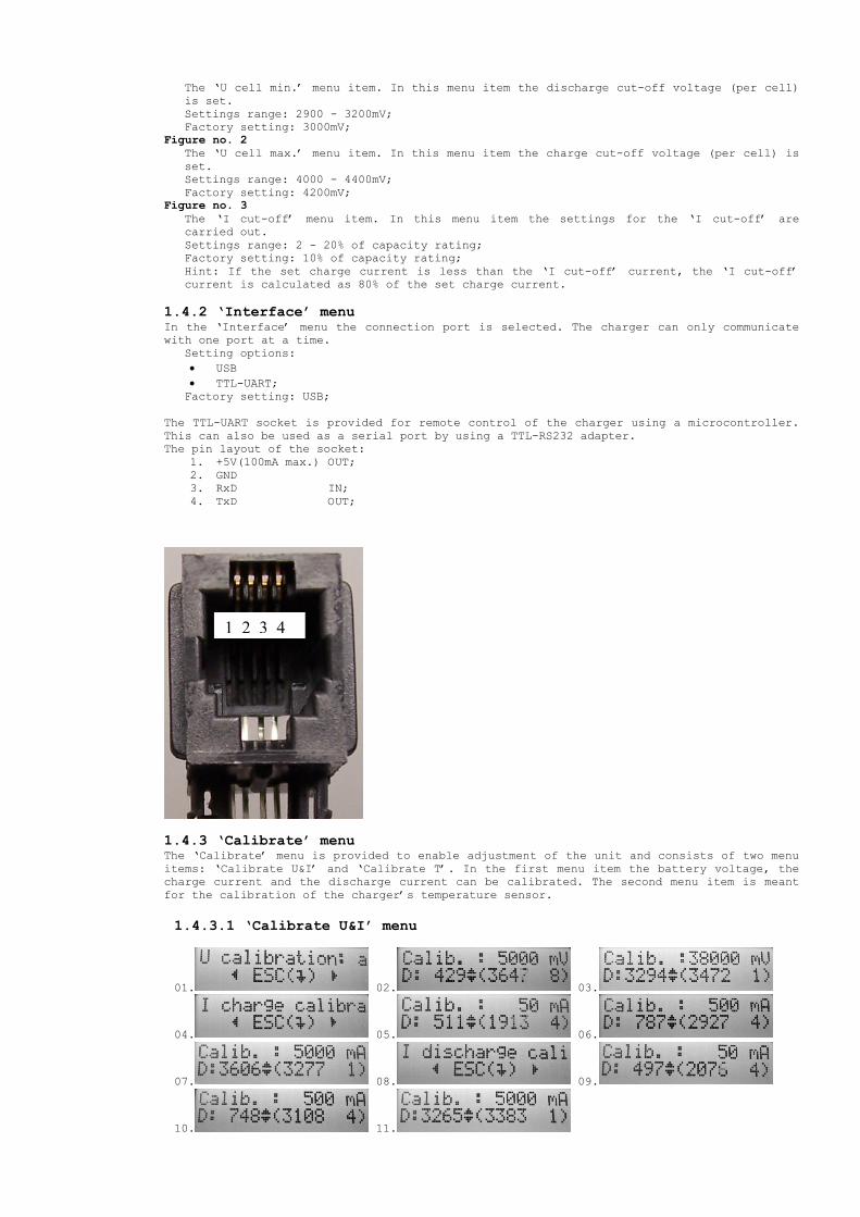
The TTL-UART socket is provided for remote control of the charger using a microcontroller. This can also be used as a serial port by using a TTL-RS232 adapter. The pin layout of the socket:
1. +5V(100mA max.) OUT; 2. GND 3. RxD IN; 4. TxD OUT;
1.4.3 ‘Calibrate’ menu The ‘Calibrate’ menu is provided to enable adjustment of the unit and consists of two menu items: ‘Calibrate U&I’ and ‘Calibrate T’. In the first menu item the battery voltage, the charge current and the discharge current can be calibrated. The second menu item is meant for the calibration of the charger’s temperature sensor.
1.4.3.1 ‘Calibrate U&I’ menu
01. 02. 03.
04. 05. 06.
07. 08. 09.
10. 11.
1 2 3 4

Figure no. 1
In this menu item we suggest connecting a voltmeter to the charger. The entire on-screen message can be browsed through using the ‘Right/Left’ keys. When the voltmeter is connected, this is confirmed with the ‘Enter’ key.
Figure no. 2
A value is indicated in the display. This should also be displayed on the voltmeter. In this case: 5000mV. Should these values differ, it can now be adjusted using the ‘Up/Down’ keys. The setting is then confirmed using the ‘Enter’ key.
Figure no. 3
The display shows the next value. This should also be shown by the voltmeter. In this case: 38000mV. Should these values differ, it can now be adjusted using the ‘Up/Down’ keys. The setting is then confirmed using the ‘Enter’ key.
Figure no. 4
In this menu item we suggest connecting an ammeter and a battery (or battery pack) to the charger. The entire on-screen message can be browsed through using the ‘Right/Left’ keys. The battery should be in an approx. ‘half-full’ state and connected in series to the ammeter. For this calibration we recommend using a 6V/10 - 20Ah lead battery. When the ammeter is connected, this is confirmed using the ‘Enter’ key.
Figure no. 5
A value is indicated in the display. This should also be displayed on the ammeter. In this case: 50mA. Should these values differ, it can now be adjusted using the ‘Up/Down’ keys. The setting is then confirmed using the ‘Enter’ key. The first step in calibrating the charge current has hereby been completed.
Figure no. 6
A value is indicated in the display. This should also be displayed on the ammeter. In this case: 500mA. Should these values differ, it can now be adjusted using the ‘Up/Down’ keys. The setting is then confirmed using the ‘Enter’ key.
Figure no. 7
A value is indicated in the display. This should also be displayed on the ammeter. In this case: 5000mA. Should these values differ, it can now be adjusted using the ‘Up/Down’ keys. The setting is then confirmed using the ‘Enter’ key.
Following the charge current calibration, the discharge current calibration is performed in exactly the same manner (Figures 8 - 11).
1.4.3.2 ‘Calibrate T’ menu During this calibration a thermometer is used as the reference instrument. Room temperature is used as the reference temperature.
01. 02.
Figure no. 1
In this menu item the ‘is’ value (top) and ‘must’ value (bottom) are displayed. If the ‘is’ value (the charger’s temperature sensor) deviates from the ‘must’ value (thermometer), it can now be adjusted using the ‘Up/Down’ keys (Figure 2). The setting
is then confirmed using the ‘Enter’ key.
2. The service programmes The following programmes are available:
• Charge;
• Discharge;
• Discharge-Charge;
• Charge-Discharge-Charge;
• Cycle;
• Forming; Each battery can only take up and store a certain amount of energy. This is called capacity or battery capacity. This capacity value is given in mAh (milliampere hours) or Ah (ampere hours) for larger batteries. As a general rule, each battery available on the open market is printed by the manufacturer with the capacity value. One refers to this printed capacity value as the capacity rating. The size of charge and discharge currents are described as a multiple of a battery's capacity rating. The symbol for this is 'C' or 'CA'. For example, if a battery with a capacity rating of 1000mAh is charged with 1/10C, then a charge current of 100 mA flows.
2.1 Charge A connected battery is charged. After charging is complete the unit switches to trickle charge. In this programme a message is displayed after charging which indicates for what reason charging was terminated. The following messages may appear:
• ‘Ich.min. reached’: The switch-off current was reached (see ‘I cut-off parameter).
This message is used when charging Pb-, Li-ion- and Li-polymer batteries.
• ‘max.temp.reached’: The maximum allowable (set) battery temperature was reached.

• ‘deltaU detected’: The Delta peak was detected. The message is used when charging NiCd
and NiMH batteries.
• ‘max.cap. reached’: The charge capacity limit was reached.
2.1.1 Hint no. 1: The trickle charge is only carried out for NiCd, NiMH and Pb batteries. Trickle charging Li-ion- and Li-polymer batteries can lead to degradation of the batteries. 2.1.2 Hint no. 2: A NiCd/NiMH battery with an unknown charge state should either be charged first of all with at least 1/2 C, in order to ensure a certain Delta peak switch-off, or fully discharged beforehand.
2.2 Discharge A connected battery is discharged until the corresponding discharge cut-off voltage, set in the ‘Setup’ menu, is reached. The remaining capacity removed from the battery is hereby measured and can be prompted on the display. At the end of this programme the battery is fully discharged. Following discharging a message appears in this programme which indicates for what reason the discharging was terminated. The following messages may appear:
• ‘Umin.dis.reached’: The minimum allowable (set) battery voltage was reached.
• ‘max.temp.reached’: The maximum allowable (set) battery temperature was reached.
Hint: When discharging a battery whose voltage is below 1,5V (e.g. single-cell NiCd and NiMH batteries), it is possible that the set discharging current will not be guaranteed, because the resistance in the ‘battery+contacts+charging cable’ chain is too high. However, in this case the discharged capacity is measured accurately as the measured discharge current (not set) is used for the calculation.
2.3 Discharge-Charge A connected battery is first fully discharged and the battery capacity measured. Next, following a set pause (service pause) the battery is fully charged again. After completion of the charging procedure the unit switches to trickle charge (see hint 2.1.1). 2.3.1 Hint no. 1: The meaning of ‘service pause’ has already been described in section 1.2. 2.3.2 Hint no. 2: This programme should always be used when a NiCd/NiMH battery with an unknown charge state is to be charged and a charge current of less than 1/2C was selected. In this case, the charging procedure is terminated after the calculated charge time (charge capacity limit).
2.4 Charge-Discharge-Charge A connected battery is first charged. Next, following a set pause, it is discharged again. The battery capacity is thereby determined in order to restart the charging of the battery following a further pause. At the end of the charging procedure the unit switches to trickle charge (see hints 2.1.1, 2.1.2 and 2.3.1).
2.5 Cycle A connected battery is automatically discharged and then charged again every 1min – 30 days. This programme is great for overwintering or training model-making and motorcycle batteries. This ensures optimum care of the batteries and a long service life. The number of charge/discharge cycles, service pauses and cycle pauses is set in the ‘Setup’ menu. 2.5.1 Hint: The meaning of ‘service pause’ and ‘cycle pause’ was described in section 1.2.
2.5 Forming A connected battery is automatically discharged and charged until the unit can no longer detect any capacity increase (up to 10%) or the set cycle number is reached. This means that at least two discharging-charging cycles must be carried out in order to obtain a result. This programme should be used for reforming new batteries or batteries that have been stored for a long time. As a rule, through this forming procedure, the batteries are restored to their capacity rating and capacity losses, that were caused by the memory effect, are restored again and predominantly eliminated. The number of discharge-charge cycles can be set between 2 and 20 cycles. As long as there are no serious defects inside the battery due to extreme overloading, reversal of cell polarity or deep discharge, this procedure, in most cases, allows full capacity to be reached in a ‘dull’ battery. This programme is also recommended for charging new batteries for the first time.
If in the aforementioned programmes the processing of a battery is refused, then the ‘manual charge’ programme is recommended for charging/refreshing/reanimating the battery (see section 1.3). When the programmes are carried out, the following error messages may be displayed: Hint: If the error message (number of characters) is longer than the display window, then the whole message can be scrolled through using the ‘Right/Left’ keys.
• ‘Error: no accu!’: During the programme it was discovered that no battery is connected.
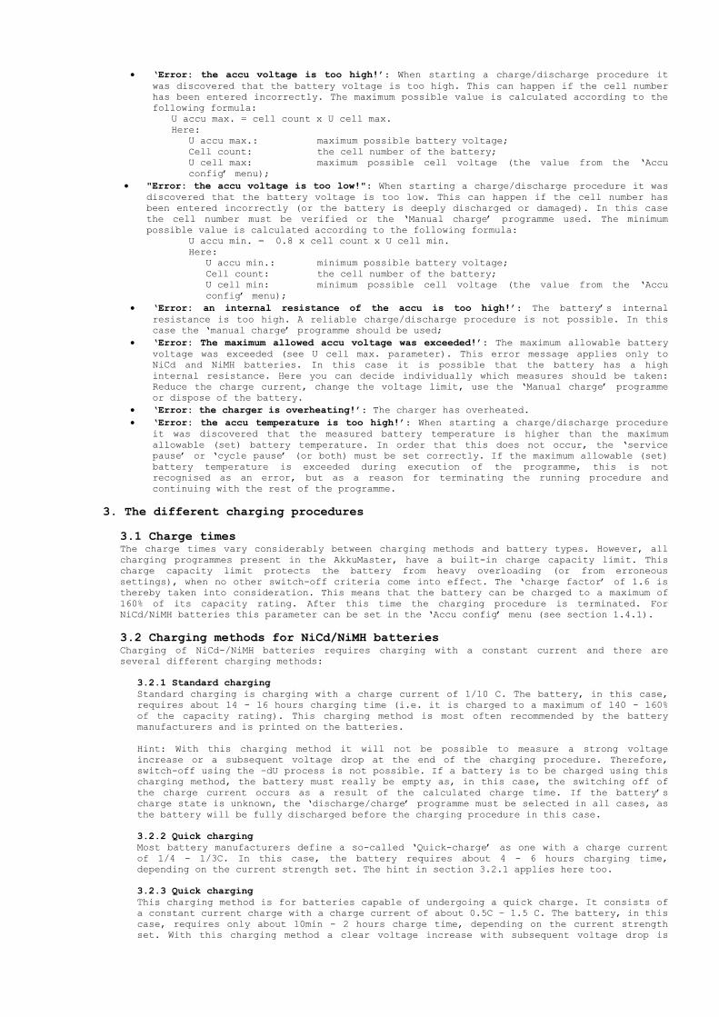
• ‘Error: the accu voltage is too high!’: When starting a charge/discharge procedure it
was discovered that the battery voltage is too high. This can happen if the cell number has been entered incorrectly. The maximum possible value is calculated according to the following formula:
U accu max. = cell count x U cell max. Here:
U accu max.: maximum possible battery voltage; Cell count: the cell number of the battery; U cell max: maximum possible cell voltage (the value from the ‘Accu config’ menu);
• "Error: the accu voltage is too low!": When starting a charge/discharge procedure it was
discovered that the battery voltage is too low. This can happen if the cell number has been entered incorrectly (or the battery is deeply discharged or damaged). In this case the cell number must be verified or the ‘Manual charge’ programme used. The minimum possible value is calculated according to the following formula:
U accu min. = 0.8 x cell count x U cell min. Here:
U accu min.: minimum possible battery voltage; Cell count: the cell number of the battery; U cell min: minimum possible cell voltage (the value from the ‘Accu config’ menu);
• ‘Error: an internal resistance of the accu is too high!’: The battery’s internal
resistance is too high. A reliable charge/discharge procedure is not possible. In this case the ‘manual charge’ programme should be used;
• ‘Error: The maximum allowed accu voltage was exceeded!’: The maximum allowable battery
voltage was exceeded (see U cell max. parameter). This error message applies only to NiCd and NiMH batteries. In this case it is possible that the battery has a high internal resistance. Here you can decide individually which measures should be taken: Reduce the charge current, change the voltage limit, use the ‘Manual charge’ programme or dispose of the battery.
• ‘Error: the charger is overheating!’: The charger has overheated.
• ‘Error: the accu temperature is too high!’: When starting a charge/discharge procedure
it was discovered that the measured battery temperature is higher than the maximum allowable (set) battery temperature. In order that this does not occur, the ‘service pause’ or ‘cycle pause’ (or both) must be set correctly. If the maximum allowable (set) battery temperature is exceeded during execution of the programme, this is not recognised as an error, but as a reason for terminating the running procedure and continuing with the rest of the programme.
3. The different charging procedures
3.1 Charge times The charge times vary considerably between charging methods and battery types. However, all charging programmes present in the AkkuMaster, have a built-in charge capacity limit. This charge capacity limit protects the battery from heavy overloading (or from erroneous settings), when no other switch-off criteria come into effect. The ‘charge factor’ of 1.6 is thereby taken into consideration. This means that the battery can be charged to a maximum of 160% of its capacity rating. After this time the charging procedure is terminated. For NiCd/NiMH batteries this parameter can be set in the ‘Accu config’ menu (see section 1.4.1).
3.2 Charging methods for NiCd/NiMH batteries Charging of NiCd-/NiMH batteries requires charging with a constant current and there are several different charging methods:
3.2.1 Standard charging
Standard charging is charging with a charge current of 1/10 C. The battery, in this case, requires about 14 - 16 hours charging time (i.e. it is charged to a maximum of 140 - 160% of the capacity rating). This charging method is most often recommended by the battery manufacturers and is printed on the batteries. Hint: With this charging method it will not be possible to measure a strong voltage increase or a subsequent voltage drop at the end of the charging procedure. Therefore, switch-off using the –dU process is not possible. If a battery is to be charged using this charging method, the battery must really be empty as, in this case, the switching off of the charge current occurs as a result of the calculated charge time. If the battery’s charge state is unknown, the ‘discharge/charge’ programme must be selected in all cases, as the battery will be fully discharged before the charging procedure in this case.
3.2.2 Quick charging
Most battery manufacturers define a so-called ‘Quick-charge’ as one with a charge current of 1/4 - 1/3C. In this case, the battery requires about 4 - 6 hours charging time, depending on the current strength set. The hint in section 3.2.1 applies here too.
3.2.3 Quick charging
This charging method is for batteries capable of undergoing a quick charge. It consists of a constant current charge with a charge current of about 0.5C – 1.5 C. The battery, in this case, requires only about 10min - 2 hours charge time, depending on the current strength set. With this charging method a clear voltage increase with subsequent voltage drop is
measurable at the end of charging. The unit recognises this voltage drop and is switched off accordingly following –dU recognition. In this way a battery must not first be fully discharged in order to prevent overloading! 3.2.4 Quick charging with temperature controlled switch-off
This charging method is ideally suited for quick charging and offers good protection from overloading and damage to the battery. The following formula may be used here:
T accu max. = T accu start + 15°C Here: T accu max.: maximum allowable battery temperature (also switch-off temperature) T accu start: battery temperature before charging (or ambient temperature)
Hint: The temperature sensor must have a good thermal contact with the battery. 3.2.5 Trickle charging
After successful termination of charging, the charger normally switches to ‘trickle charge’ mode. This trickle charging is designed to compensate for any self-discharging of the connected battery, particularly when this battery remains attached to the charger for longer periods of time. Here a charge current in the region of 0.02-0.05C is recommended by most battery manufacturers (with a possible time or battery voltage limit).
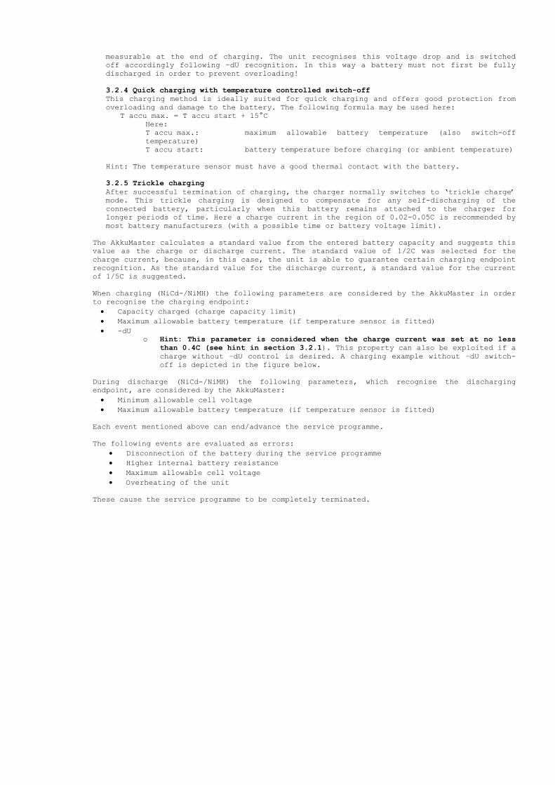
The AkkuMaster calculates a standard value from the entered battery capacity and suggests this value as the charge or discharge current. The standard value of 1/2C was selected for the charge current, because, in this case, the unit is able to guarantee certain charging endpoint recognition. As the standard value for the discharge current, a standard value for the current of 1/5C is suggested. When charging (NiCd-/NiMH) the following parameters are considered by the AkkuMaster in order to recognise the charging endpoint:
• Capacity charged (charge capacity limit)
• Maximum allowable battery temperature (if temperature sensor is fitted)
• -dU o Hint: This parameter is considered when the charge current was set at no less
than 0.4C (see hint in section 3.2.1). This property can also be exploited if a
charge without –dU control is desired. A charging example without –dU switch-off is depicted in the figure below.
During discharge (NiCd-/NiMH) the following parameters, which recognise the discharging endpoint, are considered by the AkkuMaster:
• Minimum allowable cell voltage
• Maximum allowable battery temperature (if temperature sensor is fitted)
Each event mentioned above can end/advance the service programme. The following events are evaluated as errors:
• Disconnection of the battery during the service programme
• Higher internal battery resistance
• Maximum allowable cell voltage
• Overheating of the unit These cause the service programme to be completely terminated.

A charging example for a NiMH battery without –dU switch-off.
3.3 Charging procedure for Pb-, Li-ion- and Li-polymer batteries The ideal charging procedure for these batteries is charging with IU characteristics. The battery is first charged with a constant current until the charge cut-off voltage (U cell max.) is reached. Then the voltage is held constant and the charge current adapts to the battery’s charge state. The fuller the battery the lower the charge current. If a charge current falls short by a particular value (I cut-off), the charging procedure is deemed to have ended.
The following charge parameters are recommended by the majority of battery manufacturers:
• PB
o U cell max.: 2.2 - 2.45V/cell; o I charge
§ Standard charge: 0.1C;
§ Quick charge: 0.3 - 1C; o I cut-off: 0.05 - 0.2C;
• Li-ion
o U cell max.: 4.1V/cell(1% tolerance); o I charge
§ Standard charge: 0.05 – 0.15C;
§ Quick charge: 0.5 - 1C; o I cut-off: 0.07 - 0.2C;
• Li-polymer
o U cell max.: 4.2V/cell(1% tolerance); o I charge
§ Standard charge: 0.05 – 0.15C;
§ Quick charge: 0.5 - 1C; o I cut-off: 0.07 - 0.2C;
The AkkuMaster will suggest the following standard values for the charge current:
• PB: 0.3C;
• Li-ion: 0.5C;
• Li-polymer: 0.5C;
The standard value for the discharge current is 0.2C for all three types. Hint: When charging Li-ion- and Li-polymer batteries one must be completely certain that a ‘naked’ battery is involved. Only if this is the case can AkkuMaster handle the battery

correctly. If the battery contains built-in charging or protection circuitry it can only be charged using a special charger made for that purpose. If an attempt is made to charge such a battery using the AkkuMaster, this can cause the battery to become damaged or explode.
When charging (Pb, Li-ion- and Li-polymer) the AkkuMaster evaluates the following parameters in order to recognise the charging endpoint:
• I cut-off
• Capacity charged (charge capacity limit)
• Maximum allowable battery temperature (if a temperature sensor is fitted) When discharging (Pb, Li-ion- and Li-polymer) the AkkuMaster evaluates the following parameters in order to recognise the charging endpoint:
• Minimum allowable cell voltage
• Maximum allowable battery temperature (if a temperature sensor is fitted)
Each of then aforementioned events can end/advance the service programme. The following events are evaluated as errors:
• Disconnection of the battery during the service programme
• Higher battery internal resistance
• Overheating of the unit These cause the service programme to be terminated completely.
4. The data logger The AkkuMaster has a built-in data logger, that records complete charge/discharge procedures without the need for a PC being continuously connected. These data can be read out and evaluated later. In total, the data logger can store approx. 53000 data sets. Storage is performed once every 5 seconds. When the logger’s storage space is full (after about 74 hours), recording is stopped. Hint: The ‘Service’ and ‘Cycle’ pauses are automatically removed by the data logger and not recorded. Hint: Recording always begins when a ‘start’ menu is executed. This causes previously recorded data to be erased.
Claims under guarantee: The dealer/manufacturer from whom the unit was purchased gives a 2-year warranty from the date of delivery against materials and manufacture of the product. In case of defect, the purchaser initially only has the right to subsequent performance. Subsequent performance comprises either rectification or the delivery of a replacement product. Exchanged units or parts become the property of the dealer/manufacturer. The buyer must inform the dealer of any defects found without delay. Proof of the right to claim under guarantee must be provided by means of a valid confirmation of sale (sales receipt or invoice). Damage caused by improper handling, incorrect connection, use of parts from third party manufacturers, normal wear and tear, use of force, repair attempts by the user or changes to the unit, cables or terminals, changes to the circuitry, damage caused by failure to observe the operating instructions or by improper use or other external influences, connection to the wrong voltage or type of current, accidental misuse or damage caused by careless handling, are not covered by the warranty and invalidate the right to claim under guarantee.
Advice on environmental protection: At the end of its lifespan, this product must not be disposed of in the normal household waste, but must be taken to a recycling point for electrical and electronic devices. This is indicated by the symbol on the product, operating instructions or packaging. The recyclables are reusable in accordance with their labelling. Through the reuse, recycling of materials or other means of recycling used appliances,
you are making an important contribution to protecting our environment. Disposal of used batteries! As the end-user you are legally obliged (Battery Directive) to return all used batteries; disposal through the household waste is forbidden!

Pollutant-containing batteries are labelled with symbols, which indicate the ban on disposal through the household waste. The chemical symbols for the important heavy metals are: Cd = cadmium, Hg = mercury, Pb = lead. You can dispose of your used batteries free-of-charge at collection points in your community or everywhere where batteries are sold! You thereby fulfil your legal obligations and make your contribution to protecting the environment. This operating manual is published by H-Tronic GmbH, Industriegebiet Dienhof 11, 92242 Hirschau. All rights including those of translation reserved. Any form of reproduction whatsoever; e.g. photocopying, transfer to microfilm or capture using EDP equipment, requires prior written permission from the publisher. Reprinting, including extracts, forbidden. On going to press, this operating manual correlates with the state of the technology. The right to make any changes to technology or features is reserved. c Copyright 2008 by H-Tronic GmbH.
Right to make technical changes is reserved. No claims are made as to the completeness of figures depicted. H-Tronic GmbH, Industriegebiet Dienhof 11, 92242 Hirschau, Tel. +49 (0)9622 70200, Fax +49 (0)9622 702020, Internet www.h-tronic.de.