operating instructions english xarios multi … om x mt... · 62--61179--01 3 operating...
TRANSCRIPT
362--61179--01
OPERATING INSTRUCTIONS english
XARIOS MULTI TEMPERATURE ROAD / STANDBY
X350--04 Mt_ X600 Mt_
1. INTRODUCTION
This guide has been prepared for the operator of Carrier Transicold refrigeration units. It contains basicinstructions for the daily operation of the refrigeration unit as well as safety information, troubleshooting tips,and other information that will help you to deliver the load in the best possible condition.
Xarios range is simple, tried and tested design; low--cost purchase and operation to equipmiddle size deliveryvehicles.
Please take the time to read the information contained in this booklet and refer to it whenever you have aquestion about the operation of your Carrier Transicold unit. This manual refers to the standard model. Someoptions may not appear in it, and in such cases you are requested to consult our Technical Services.
Your refrigeration unit has been engineered to provide long, trouble--free performance when it is properlyoperated and maintained. The checks outlined in this guide will help to minimize on the road problems. Inaddition, a comprehensive maintenance programwill help to insure that the unit continues to operate reliably.Such a maintenance program will also help to control operating costs, increase the unit’s working life, andimprove performance.
When having your unit serviced, be sure to specify genuine Carrier Transicold replacement parts for thehighest quality and best reliability.
At Carrier Transicold, we are continually working to improve the products that we build for our customers. Asa result, specifications may change without notice.
CONTENTS
1. Introduction 3. . . . . . . . . . . . . . . . . . . . . . . . . . . . . . . . . . . . . . . . . . . . . . . . . .2. Identification 5. . . . . . . . . . . . . . . . . . . . . . . . . . . . . . . . . . . . . . . . . . . . . . . . . .2.1.Nameplate 5. . . . . . . . . . . . . . . . . . . . . . . . . . . . . . . . . . . . . . . . . . . . . . . . . .
2.2.Noise level sticker (fixed if available) 5. . . . . . . . . . . . . . . . . . . . . . . . . . . . .
2.3. Installation 5. . . . . . . . . . . . . . . . . . . . . . . . . . . . . . . . . . . . . . . . . . . . . . . . . .
3. Warnings and precautions 5. . . . . . . . . . . . . . . . . . . . . . . . . . . . . . . . . . . . . .3.1.Warning stickers maintenance 9. . . . . . . . . . . . . . . . . . . . . . . . . . . . . . . . . .
4. Product loading 9. . . . . . . . . . . . . . . . . . . . . . . . . . . . . . . . . . . . . . . . . . . . . . .5. Recommended transport temperatures 11. . . . . . . . . . . . . . . . . . . . . . . . . .6. Quick glance on the display board 11. . . . . . . . . . . . . . . . . . . . . . . . . . . . . .6.1.Cab control 11. . . . . . . . . . . . . . . . . . . . . . . . . . . . . . . . . . . . . . . . . . . . . . . . . .
4 62--61179--01
7. Operation 12. . . . . . . . . . . . . . . . . . . . . . . . . . . . . . . . . . . . . . . . . . . . . . . . . . . .7.1.Operating principle 12. . . . . . . . . . . . . . . . . . . . . . . . . . . . . . . . . . . . . . . . . . .7.1.1. In ROAD mode 12. . . . . . . . . . . . . . . . . . . . . . . . . . . . . . . . . . . . . . . . .7.1.2. In STANDBY mode 12. . . . . . . . . . . . . . . . . . . . . . . . . . . . . . . . . . . . .7.1.3. Temperature control 12. . . . . . . . . . . . . . . . . . . . . . . . . . . . . . . . . . . . .7.1.4. Defrost 13. . . . . . . . . . . . . . . . . . . . . . . . . . . . . . . . . . . . . . . . . . . . . . . .7.1.5. Heating 13. . . . . . . . . . . . . . . . . . . . . . . . . . . . . . . . . . . . . . . . . . . . . . .7.1.6. Control components 13. . . . . . . . . . . . . . . . . . . . . . . . . . . . . . . . . . . . .
7.2.Operation on ROAD mode 14. . . . . . . . . . . . . . . . . . . . . . . . . . . . . . . . . . . . .7.2.1. Starting the unit 14. . . . . . . . . . . . . . . . . . . . . . . . . . . . . . . . . . . . . . . . .7.2.2. Compartment shut--down 14. . . . . . . . . . . . . . . . . . . . . . . . . . . . . . . . .7.2.3. Stoping the unit 14. . . . . . . . . . . . . . . . . . . . . . . . . . . . . . . . . . . . . . . . .
7.3.Operation on STANDBY mode 15. . . . . . . . . . . . . . . . . . . . . . . . . . . . . . . . . .7.3.1. Starting the unit 15. . . . . . . . . . . . . . . . . . . . . . . . . . . . . . . . . . . . . . . . .7.3.2. Compartment shut--down 15. . . . . . . . . . . . . . . . . . . . . . . . . . . . . . . . .7.3.3. Stoping the unit 15. . . . . . . . . . . . . . . . . . . . . . . . . . . . . . . . . . . . . . . . .7.3.4. Standby operation guidelines 16. . . . . . . . . . . . . . . . . . . . . . . . . . . . .
7.4. To change display brightness 17. . . . . . . . . . . . . . . . . . . . . . . . . . . . . . . . . . .
7.5. To change setpoint temperature 17. . . . . . . . . . . . . . . . . . . . . . . . . . . . . . . . .
7.6. To change defrost parameters 17. . . . . . . . . . . . . . . . . . . . . . . . . . . . . . . . . .
7.7. To change other datas 18. . . . . . . . . . . . . . . . . . . . . . . . . . . . . . . . . . . . . . . . .
7.8. To change default parameters 18. . . . . . . . . . . . . . . . . . . . . . . . . . . . . . . . . .
7.9. Fault alarm display 19. . . . . . . . . . . . . . . . . . . . . . . . . . . . . . . . . . . . . . . . . . .
8. Maintenance 21. . . . . . . . . . . . . . . . . . . . . . . . . . . . . . . . . . . . . . . . . . . . . . . . . .8.1.Maintenance schedule 21. . . . . . . . . . . . . . . . . . . . . . . . . . . . . . . . . . . . . . . .
8.2.Services description 22. . . . . . . . . . . . . . . . . . . . . . . . . . . . . . . . . . . . . . . . . .
9. A.T.P. Europe Regulation extract 23. . . . . . . . . . . . . . . . . . . . . . . . . . . . . . . .10. 24h Assistance 24. . . . . . . . . . . . . . . . . . . . . . . . . . . . . . . . . . . . . . . . . . . . . . . .
562--61179--01
2. IDENTIFICATION
Keep the fold out sheet while reading the instructions.
2.1. NameplateEach unit is identified by a nameplate attached to the frame of the unit.The nameplate identifies the completemodel number of the unit, the serial number and some other information.
If a problem occurs, please refer to the information on this plate, and make a note of the model and serialnumber before calling for assistance. This information will be needed when you contact a technician so thathe may properly assist you.
The complete nameplate is fixed on the frame (1a) and the Serial Number is fixed on unit side (1b) : easilyreadable.
2.2. Noise level sticker (fixed if available)
This sticker indicates the noise level in Lwa (accoustic pressure).
2.3. Installation
Xarios are manufactured as a split--system, enabling them to adapt to any vehicle and any configuration.
a. Evaporators
b. Condenser
c. Cab control
d. Compressor mounting kit
e. Vehicle battery
f. Standby plug
g. Main road fuse
3. WARNINGS AND PRECAUTIONS
This manual contains safety and service instructions to follow in order to prevent any accident. Some offollowing stickers have been placed on the product for your SAFETY.
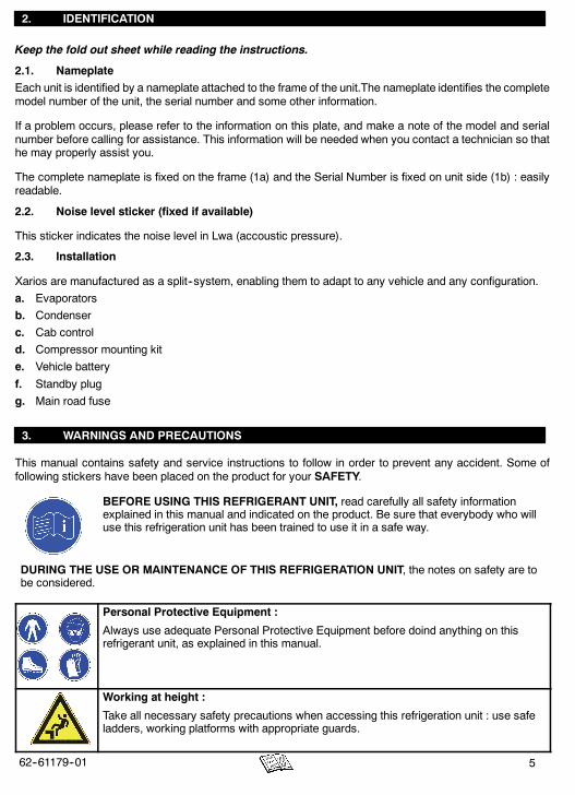
BEFORE USING THIS REFRIGERANT UNIT, read carefully all safety informationexplained in this manual and indicated on the product. Be sure that everybody who willuse this refrigeration unit has been trained to use it in a safe way.
DURING THE USE OR MAINTENANCE OF THIS REFRIGERATION UNIT, the notes on safety are tobe considered.
Personal Protective Equipment :
Always use adequate Personal Protective Equipment before doind anything on thisrefrigerant unit, as explained in this manual.
Working at height :
Take all necessary safety precautions when accessing this refrigeration unit : use safeladders, working platforms with appropriate guards.
6 62--61179--01
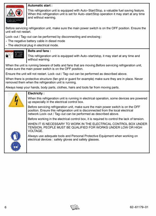
Automatic start :
This refrigeration unit is equipped with Auto--Start/Stop, a valuable fuel saving feature.When this refrigeration unit is set for Auto--start/Stop operation it may start at any timeand without warning.
Before servicing refrigeration unit, make sure the main power switch is on the OFF position. Ensure theunit will not restart.
Lock--out / Tag--out can be performed by disconnecting and enclosing :-- The negative battery cable in diesel mode-- The electrical plug in electrical mode.
Belts and fans :
This refrigeration unit is equipped with Auto--start/stop, it may start at any time andwithout warning.
When the unit is running beware of belts and fans that are moving.Before servicing refrigeration unit,make sure the main power switch is on the OFF position.
Ensure the unit will not restart. Lock--out / Tag--out can be performed as described above.
When there is protective structure (fan grid or guard for example) make sure they are in place. Neverremoved them when the refrigeration unit is running.
Always keep your hands, body parts, clothes, hairs and tools far from moving parts.
Electricity :
When this refrigeration unit is running in electrical operation, some devices are poweredup especially in the electrical control box.
Before servicing refrigeration unit, make sure the main power switch is on the OFFposition. Ensure this refrigeration unit is disconnected from the local electricalnetwork.Lock--out / Tag--out can be performed as described above.
Before working in the electrical control box, it is required to control the lack of tension.
WHEN IT IS NECESSARY TO WORK IN THE ELECTRICAL CONTROL BOX UNDERTENSION, PEOPLE MUST BE QUALIFIED FOR WORKS UNDER LOW OR HIGHVOLTAGE.
Always use adequate tools and Personal Protective Equipment when working onelectrical devices : safety gloves and safety glasses.

762--61179--01
Engine coolant :
This refrigeration unit is equipped with a pressurised cooling system. Under normaloperating conditions, the coolant in the engine and radiator is under high pressure andvery hot.
Coolant is very slippery. It can be harmful in case of ingestion.
Never remove the cap from a hot radiator when this refrigeration unit is running orimmediately after.
If the cap must be removed, wait at least 10 minutes and then do so very slowly inorder to release the pressure without spray.
In case of leakage, immediatly clean the floor to prevent slipping.
Avoid contact with the skin and eyes. Always use Personal Protective Equipment whenhandling engine coolant : safety clothes, safety gloves and safety glasses.
Refrigerant :
The refrigerant contained in this refrigeration unit can cause frosbite, severe burns orblindness in case of projection and direct contact with the skin or eyes.
In contact with flame or heat refrigerant generate toxic gas.
Refrigerant handling must be done by qualified people.
Keep any flame, any lighted object or any source of sparks away from the refrigerantunit.
Always use Personal Protective Equipment when handling refrigerant : safety clothes,safety gloves and safety glasses.
First aid in case of frost--bite :
a. Cover up the frost--bitten part.
b. Quickly warm up the frost--bitten part by dipping it into lukewarmwater (not hot). If youdon’t have water, wrap the injured part in a clean cloth.
c. If refrigerant fluid has been splashed into your eyes, rinse them immediately withcleanwater. As a precaution, you are recommended to have amedical examination as well.
Burning with hot and cold :
When this refrigeration unit is running or even after, different components can be verycold or hot (exhaust pipe, tubes, coils, receiver, accumulator or engine for example)
Beware when operating closed from cold or hot components.
Always use adequate safety gloves when doing any maintenance on this refrigerationunit.
Cuttings :
Beware when handling or operating closed from parts that could be sharp (coils,evaporators, clamps for example).
Always use adequate safety gloves when doing any maintenance on this refrigerationunit.
8 62--61179--01
Battery :
This refrigeration unit may be equipped with a lead--acid type battery. When chargingthe battery normally vents small amounts of flammable and explosive hydrogen gas.
Projections of acids on the skin or eyes can cause severe burns.
Keep any flame, any lighted object or any source of sparks away from the batteryelements.
Always use Personal Protective Equipment when handling and charging battery: safetyclothes, safety gloves and safety glasses.
Cooling oil :
- avoid prolonged or repeated contact with the skin.
- wash carefully after handling.
“Low pollution” engine :
- The TRI--VORTEX--type indirect injection system minimizes exhaust fume pollution.
- NEVER START THE ENGINE IN A CLOSED ROOM, EXHAUST GAS ISPOISONOUS.
- It is colorless and odorless and created by the incomplete combustion ofhydrocarbons.
- Exhaust gas is poisonous, breathing it in induces drowsiness and may lead toloss of consciousness.
The following symptoms indicate exhaust gas has been inhaled :
- Blackout, intense headache, sudden weakness and sleepiness, vomiting, muscularcontractions, beating temples.
If you feel one of the above mentioned symptoms, go out and breathe fresh air.
If you notice a noise or modification of the exhaust system, immediately stop the engineand call your service centre for checking and repair.
Environment :
Think about protection of environment during all the life of this refrigeration unit.
To prevent environmental damages NEVER release refrigerant in the atmosphere, NEVER throwcoolant, oil, battery and chemicals in the nature. It must be recuperate and recycle according to currentregulations.
When disposing this refrigerant unit do it in an environmentally sound way and in accordance withcurrent regulations.

962--61179--01
CAUTION
Under no circumstances should anyone attempt to repair the Logic or DisplayBoards. Should a problem develop with these component, contact your nearestCarrier Transicold dealer for replacement.
Under no circumstances should a technician electrically probe the processor at any point, otherthan the connector terminals where the harness attaches. Microprocessor components operate atdifferent voltage levels and at extremely low current levels. Improper use of voltmeters, jumperwires, continuity testers, etc. could permanently damage the processor.
Most electronic components are susceptible to damage caused by electrical static discharge(ESD). In certain cases, the human body can have enough static electricity to cause resultantdamage to the components by touch. This is especially true of the integrated circuits found on thetruck/trailer microprocessor.
3.1. Warning stickers maintenance
a. Keep the warning pictograms clean and without any obstruction material.
b. Clean the pictograms with water and soap and wipe them with soft fabric.
c. Replace damaged or missing pictograms with new pictograms available in Carrier network.
d. If a component having a pictogram is replaced by a new one, be sure that the new component has theright pictogram.
e. Place awarning pictogramby applying it on a dry surface. Press to external sides to eliminate air bubbles.
4. PRODUCT LOADING
Proper air circulation in the trailer body, air that can move around and through the load, is a critical elementin maintaining product quality during transport. If air cannot circulate completely around the load, hot spots ortop--freeze can occur.
The use of pallets is highly recommended. Pallets, when loaded so air can flow freely through the pallets toreturn to the evaporator, help protect the product from heat passing through the floor of the truck. When usingpallets, it is important to refrain from stacking extra boxes on the floor at the rear of the truck, because this willcut off the airflow.
Product stacking is another important factor in protecting the product. Products that generate heat, fruits andvegetables for example, should be stacked so the air can flow through the product to remove the heat; thisis called “air stacking” the product. Products that do not create heat, meats and frozen products, should bestacked tightly in the center of the trailer. All products should be kept away from the sidewalls of the body, allo-wing air to flow between the body and the load; this prevents heat filtering through the walls from affecting theproduct.
It is important to check the temperature of the product being loaded to ensure that it is at the correcttemperature for transport. The refrigeration unit is designed to maintain the temperature of the product at thetemperature at which it was loaded; it was not designed to cool a warm product.
OPTIONS FOR INSULATED BODIES
D Mobile partition
The mobile partition must be placed at a minimum distance from the evaporator of 500 mm.
D Ducting of evaporator air outlet
Ventilation ducts must never be covered.
10 62--61179--01
SOME ADVICE
Before loading
D Pre--cool the inside of the insulated body by lowering the temperature for about 15 minutes.
D Evacuate the humidity existing inside the box by carrying out a manual defrost. This can only take placewhen enabled by the defrost thermostat (box temperature lower than 3_C.
D Evaporator fans are protected by safety grills. In the event of heavy duty use of the unit, ice can accumulateon the grills. It is therefore recommended to clean them regularly by means of a small brush. The operationMUST be done when the unit has been SHUT DOWN.
When loading
D To be carried out with the unit stopped.
D It is recommended to open doors as little as possible to avoid the intake of hot air and humidity.
D Select the temperature by means of the thermostat, according to the transported goods.
D Check the internal temperature of the goods being loaded (using a probe thermometer).
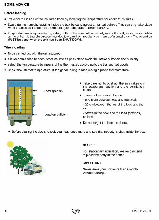
Load spacers
Load on pallets
D Take care not to obstruct the air intakes onthe evaporator section and the ventilationducts.
D Leave a free space of about :- 6 to 8 cm between load and frontwall,
- 20 cm between the top of the load and theroof,
- between the floor and the load (gratings,pallets).
D Do not forget to close the doors.
D Before closing the doors, check your load once more and see that nobody is shut inside the box.
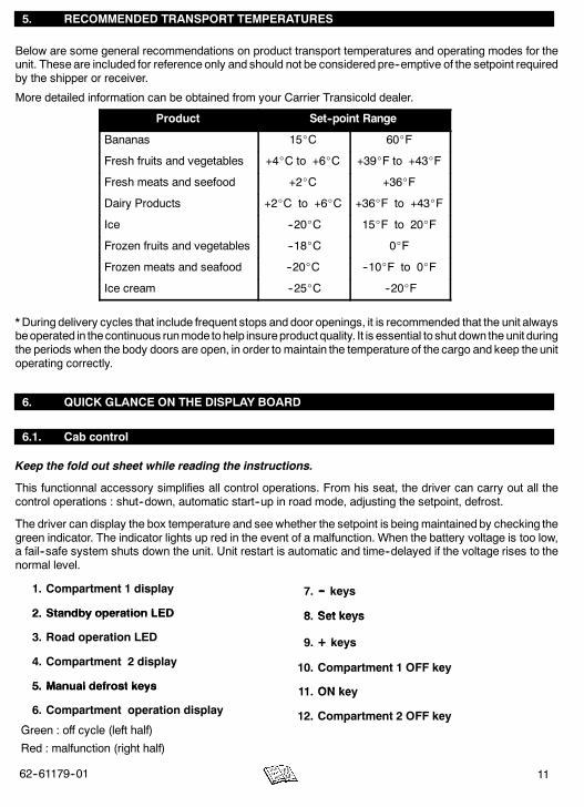
NOTE :
For stationnary utilization, we recommendto place the body in the shade.
IMPORTANT
Never leave your unit more than amonthwithout running.
1162--61179--01
5. RECOMMENDED TRANSPORT TEMPERATURES
Below are some general recommendations on product transport temperatures and operating modes for theunit. These are included for reference only and should not be considered pre--emptive of the setpoint requiredby the shipper or receiver.
More detailed information can be obtained from your Carrier Transicold dealer.
Product Set--point Range
Bananas 15_C 60_F
Fresh fruits and vegetables +4_C to +6_C +39_F to +43_F
Fresh meats and seefood +2_C +36_F
Dairy Products +2_C to +6_C +36_F to +43_F
Ice --20_C 15_F to 20_F
Frozen fruits and vegetables --18_C 0_F
Frozen meats and seafood --20_C --10_F to 0_F
Ice cream --25_C --20_F
* During delivery cycles that include frequent stops and door openings, it is recommended that the unit alwaysbeoperated in thecontinuous runmode tohelp insureproduct quality. It is essential to shut down the unit duringthe periods when the body doors are open, in order to maintain the temperature of the cargo and keep the unitoperating correctly.
6. QUICK GLANCE ON THE DISPLAY BOARD
6.1. Cab control
Keep the fold out sheet while reading the instructions.
This functionnal accessory simplifies all control operations. From his seat, the driver can carry out all thecontrol operations : shut--down, automatic start--up in road mode, adjusting the setpoint, defrost.
The driver can display the box temperature and see whether the setpoint is beingmaintained by checking thegreen indicator. The indicator lights up red in the event of a malfunction. When the battery voltage is too low,a fail--safe system shuts down the unit. Unit restart is automatic and time--delayed if the voltage rises to thenormal level.
1. Compartment 1 display
2. Standby operation LED
7. -- keys
8 Set keys2. Standby operation LED
3. Road operation LED
8. Set keys
9. + keys
4. Compartment 2 display
5. Manual defrost keys
y
10. Compartment 1 OFF key
11 ON key5. Manual defrost keys
6. Compartment operation display
G ff l (l ft h lf)
11. ON key
12. Compartment 2 OFF keyGreen : off cycle (left half)
Red : malfunction (right half)
p y

12 62--61179--01
7. OPERATION
Keep the fold out sheet while reading the instructions.
7.1. Operating principle
After startingup, the refrigerationunit by pressing theON (11.) key, unit start--up andshut--downareautomatic.
7.1.1. In ROAD mode
An open--type compressor is driven by the engine of the vehicle. The vehicle battery (alternator) powers theevaporator and condenser fans. The unit automatically shuts down when the engine is switched off with theignition key.
7.1.2. In STANDBY mode
A standby compressor is energized, and a transformer is used to power the evaporator and condenser fans.The power network connection is detected by the Cab Command which automatically starts up the unit inStandby mode.
If the ignition key is switched on while the unit is connected to the power network, or vice--versa, the CabCommand triggers a visual alarm, in the form of a flashing red malfunction light and readout.
As soon as one operating mode is inhibited, the unit automatically starts up in the other mode. An output fora buzzer alarm is available on the unit.
In all cases the unit can be completely shut down manually by pressing both OFF1 AND OFF2 keys on theCab Command.
7.1.3. Temperature control
The new and innovative multi--temp logic is able to manage separately or simultaneously the cool, heat anddefrost functions required by the different compartments according to two operating modes : “Automatic” and“Priority”.In “Automatic” mode, the thermostatic status required by the both compartments are satisfied as liquid orhot gas valve is energized simultaneously, according to a PPWM logic.
In “Priority”mode, the thermostatic status of the priority compartment is satisfied first. It benefits from100%of the unit cooling or heating capacity until its setpoint is reached. The other compartment cooling or heatingneeds will be met according to a PRIO-logic unless the priority compartment temperature is not affected.
Whatever the operating mode, as soon as the set--point temperature of any compartment has been reached,its liquid or hot gas valve is disenergized. The temperature control is obtained according to either PPWM orPRIO depending on the operating mode
As soon as the both compartements setpoint temperatures have been reached, the standby compressor isshut down. On road mode, this shut-down is done by the road compressor electro-magnetic clutch.
The condenser and evaporator fans cut out during regulation. When transporting fragile loads such as freshmeat, vegetables and cheese, it is possible to program the microprocessor to obtain continuous ventilationby the evaporator during regulation.
1362--61179--01
7.1.4. Defrost
Two defrost modes are available : “Individual or simultaneous”
In “Individual” mode, each compartment defrost parameters are set individually, in either manual ofautomatic defrost, with the appropriate compartement setting keys. Defrost cycle termination is controlled bythe appropriate compartment defrost thermostat.
In “Simultaneous” mode, defrost parameters are set for both compartments with any of the bothcompartements setting keys. Defrost starts in the both compartments simultaneously in either manual orautomatic defrost. Defrost cycle termination is controlled by the both defrost thermostats.
- Defrost operation is fully automatic but can be manually controlled if enabled by the defrostthermostat.
- Defrost cycles are fully controlled by the integrated microprocessor.
- During the defrost cycle, the evaporator fan shuts down. The condenser fan is controlled by themicroprocessor.
- During the defrost cycle, the Cab Command display indicates “d F”.
7.1.5. Heating
- The unit is equipped with hot gas heating system.
- The evaporator fan operates, the condensor fan is controlled by the microprocessor.
7.1.6. Control components
Cab control :
- Automatic selection of road or standby operation.
- Shut--down.
- Manual defrost.
- Thermostat control.
- Error messages in the event of unit malfunction.
- Programming to customize unit operation to your own requirements.

14 62--61179--01
7.2. Operation on ROAD mode
7.2.1. Starting the unit
1. Check the belt tension of the charge alternator and road compressor drive belts.
2. Start the vehicle engine.
3. Start the unit by pressing the ON key (11.). Start--up is time--delayed for 40 seconds.
4. The digital displays (1. and 4.) of the cab control displays the boxes temperature.
5. Check whether each temperature setpoint is correct by pressing the corresponding SET key (8.). Thesetpoint temperature is highlighted on the digital display.
6. Enter a new setpoint if necessary (see temperature setpoint adjustment 7.5. -- page 17).
In the event of difficulty on start--up, check that :
The main road fuse has not blown (g. -- p. 5)
The temperature selected by the cab control has not been affected.
7.2.2. Compartment shut--down
1. Press the OFF key (10. or 12.) of the corresponding compartment.
7.2.3. Stoping the unit
1. For a short stop (ie : delivery) : switch off by the vehicle ignition key.
2. For a long stop : press the both OFF1 and OFF2 keys (10. and 12.).

1562--61179--01
7.3. Operation on STANDBY mode
VERY IMPORTANT
THE UNIT MUST BE SHUT--DOWN BEFORE CONNECTING OR DISCONNECTING THESTANDBY SUPPLY CABLE !
1. Before starting :
- On the power network : check that the type of current corresponds to the characteristics of theunit (see paragraph 7.3.4.).
- On the unit : connect the unit to the power network.
7.3.1. Starting the unit
2. Start the unit by pressing the ON key (11.). Start--up is time--delayed for 10 seconds.
3. The digital displays (1. and 4.) of the cab control displays the boxes temperature.
4. Check the temperature setpoint is correct by pressing the SET key (8.). The setpoint temperature ishighlighted on the digital display.
5. Enter a new setpoint if necessary (see temperature setpoint adjustment 7.5. -- page 17).
In the event of difficulty on start--up, check that :
Network supply is ok.
The control box fuses have not blown (refer to the electric schematic supplied with the unit).
The temperature selected by the cab control has not been affected.
7.3.2. Compartment shut--down
1. Press the OFF key (10. or 12.) of the corresponding compartment.
7.3.3. Stoping the unit
1. Press the both OFF1 and OFF2 keys (10. and 12.).
16 62--61179--01
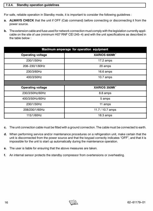
7.3.4. Standby operation guidelines
For safe, reliable operation in Standby mode, it is important to consider the following guidelines :
a. ALWAYS CHECK that the unit if OFF (Cab command) before connecting or disconnecting it from thepower source.
b. Theextensioncableand fuseused for network connectionmust complywith the legislation currently appli-cable on the site of use (minimum H07 RNF CEI 245--4) and with the unit specifications as described inthe table below :
Maximum amperage for operation equipmentMaximum amperage for operation equipment
Operating voltage XARIOS 600Mt˚
230/1/50Hz 17.2 amps
208--230/1/60Hz 20 amps
230/3/60Hz 16.6 amps
400/3/50Hz 10.7 amps
Operating voltage XARIOS 350Mt˚
230/3/50Hz/60Hz 8.8 amps
400/3/50Hz/60Hz 5 amps
230/1/50Hz 11 amps
208/230/1/60Hz 11.7 / 10.7 amps
115/1/60Hz 18.3 amps
c. The unit connection cable must be fittedwith a ground connection. The cablemust be connected to earth.
d. When performing service and/or maintenance procedures on a refrigeration unit, make certain that theunit is disconnected from the power source and that the keypad correctly indicates “OFF”, and that it isimpossible for the unit to start up automatically during the maintenance operation.
e. The user is liable for ensuring that the above measures are taken.
f. An internal sensor protects the standby compressor from overtensions or overheating.
1762--61179--01
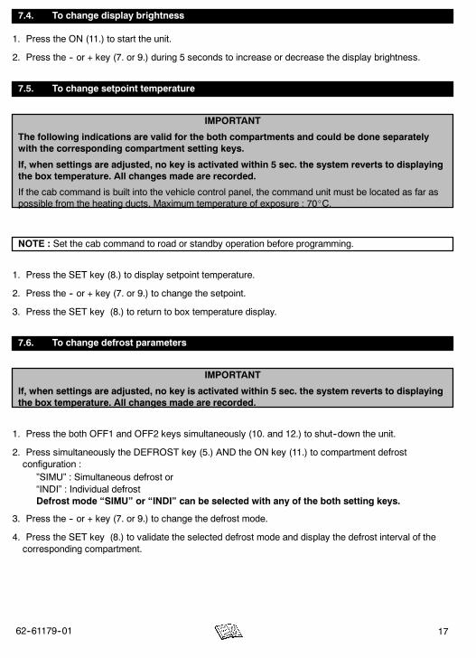
7.4. To change display brightness
1. Press the ON (11.) to start the unit.
2. Press the -- or + key (7. or 9.) during 5 seconds to increase or decrease the display brightness.
7.5. To change setpoint temperature
IMPORTANT
The following indications are valid for the both compartments and could be done separatelywith the corresponding compartment setting keys.
If, when settings are adjusted, no key is activated within 5 sec. the system reverts to displayingthe box temperature. All changes made are recorded.
If the cab command is built into the vehicle control panel, the command unit must be located as far aspossible from the heating ducts. Maximum temperature of exposure : 70_C.
NOTE : Set the cab command to road or standby operation before programming.
1. Press the SET key (8.) to display setpoint temperature.
2. Press the -- or + key (7. or 9.) to change the setpoint.
3. Press the SET key (8.) to return to box temperature display.
7.6. To change defrost parameters
IMPORTANT
If, when settings are adjusted, no key is activated within 5 sec. the system reverts to displayingthe box temperature. All changes made are recorded.
1. Press the both OFF1 and OFF2 keys simultaneously (10. and 12.) to shut--down the unit.
2. Press simultaneously the DEFROST key (5.) AND the ON key (11.) to compartment defrostconfiguration :
”SIMU” : Simultaneous defrost or“INDI” : Individual defrostDefrost mode “SIMU” or “INDI” can be selected with any of the both setting keys.
3. Press the -- or + key (7. or 9.) to change the defrost mode.
4. Press the SET key (8.) to validate the selected defrost mode and display the defrost interval of thecorresponding compartment.

18 62--61179--01
5. Press the -- or + key (7. or 9.) to change the defrost interval :
00 : inhibit defrost function.0,5 to 0,9 : Decrease time interval between 2 automatic defrost cycles in relation to calculated time.AUT (coefficient 1) : microprocessor--optimized automatic defrost according to type of cargotransported. (Variable intervals)1,1 à 1,5 : Increase time interval between 2 automatic defrost cycles in relation to calculated time.1 H, 2 H,... 6 H: Fixed defrost interval in hours.
6. Press the SET key (8.) to return to box temperature display.
7.7. To change other datas
IMPORTANT
If, when settings are adjusted, no key is activated within 5 sec. the system reverts to displayingthe box temperature. All changes made are recorded.
The following process is the same for each compartment.
1. Press the SET key (8.) during 5 seconds to enable access to malfunction codes (see 7.9. for alarmlist).
2. Press the -- or + key (7. or 9.) to display alarms
3. Press the SET key (8.) to display software versions.
4. Press the + key (9.) to display cab command software version.
5. Press the SET key (8.) to display road hourmeter.
6. Press the SET key (8.) to display standby hourmeter.
7. Press the DEFROST key (5.) to display the defrost interval (mn) calculated by the microprocessorbetween 2 defrosts.
8. Press the DEFROST key (5.) again to display elapsed time (mn) since the last defrost.
9. Press the SET key (8.) to return to box temperature display.
7.8. To change default parameters
IMPORTANT
If, when settings are adjusted, no key is activated within 5 sec. the system reverts to displayingthe box temperature. All changes made are recorded. Malfunction codes remain displayed.
1. Press simultaneously the -- and + and DEFROST keys (7. and 9. and 5.) to display operating modeselection.
2. Press the -- or + key (7. or 9.) to change the operating mode : “AUT” (automatic) or “PriO” (priority).
3. Press the SET key (8.) to validate the operating mode of selected compartment and display theminimum setpoint.
4. Press the -- or + key (7. or 9.) to change the minimum setpoint : 0_C, - 20_C or - 29_C (default value--29_C)
1962--61179--01
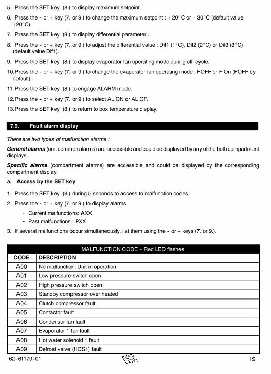
5. Press the SET key (8.) to display maximum setpoint.
6. Press the -- or + key (7. or 9.) to change the maximum setpoint : + 20_C or + 30_C (default value+20_C)
7. Press the SET key (8.) to display differential parameter .
8. Press the -- or + key (7. or 9.) to adjust the differential value : Dif1 (1_C), Dif2 (2_C) or Dif3 (3_C)(default value Dif1).
9. Press the SET key (8.) to display evaporator fan operating mode during off--cycle.
10.Press the -- or + key (7. or 9.) to change the evaporator fan operating mode : FOFF or F On (FOFF bydefault).
11.Press the SET key (8.) to engage ALARM mode.
12.Press the -- or + key (7. or 9.) to select AL ON or AL OF.
13.Press the SET key (8.) to return to box temperature display.
7.9. Fault alarm display
There are two types of malfunction alarms :
General alarms (unit commonalarms) are accessible andcould bedisplayed by any of the bothcompartmentdisplays.
Specific alarms (compartment alarms) are accessible and could be displayed by the correspondingcompartment display.
a. Access by the SET key
1. Press the SET key (8.) during 5 seconds to access to malfunction codes.
2. Press the -- or + key (7. or 9.) to display alarms
- Current malfunctions: AXX
- Past malfunctions : PXX
3. If several malfunctions occur simultaneously, list them using the -- or + keys (7. or 9.).
MALFUNCTION CODE -- Red LED flashes
CODE DESCRIPTION
A00 No malfunction. Unit in operation
A01 Low pressure switch open
A02 High pressure switch open
A03 Standby compressor over heated
A04 Clutch compressor fault
A05 Contactor fault
A06 Condenser fan fault
A07 Evaporator 1 fan fault
A08 Hot water solenoid 1 fault
A09 Defrost valve (HGS1) fault

20 62--61179--01
MALFUNCTION CODE -- Red LED flashes
A10 Liquid injection valve fault
A11 Hot gas valve (HGS2) fault
A12 High temperature 1 alarm
A13 Low temperature 1 alarm
A14 Compartment 1 Defrost alarm > 45 minutes
A15 Setpoint 1 adjusted out of the range - 29_C / +30_C
A16 Drain water resistor (DWR1) fault
A17 Thermal break down standby transformer or diode bridge protection fault
A18 Electrical heating relay (EHR1) fault
A19 Liquid solenoid valve (LV1) fault
A20 LP standby pressure switch opened
A21 Open circuit contactor compressor
A22 Open circuit condenser fan
A23 Open circuit hot water solenoid 1
A24 Open circuit defrost valve (HGS1)
A25 Open circuit liquid injection valve
A26 Open circuit hot gas valve (HGS2)
A27 Open circuit drain water resistor (DWR1)
A28 Open circuit electrical heating relay (EHR1)
A29 Open circuit liquid valve (LV1)
A30 Liquid valve (LV2) fault
A31 Defrost valve (HGS3) fault
A32 Hot water solenoid 2 fault
A33 Open circuit electrical heating relay (EHR2)
A34 Drain water resistor (DWR2) fault
A35 Evaporator 2 fan fault
A36 High temperature 2 alarm
A37 Low temperature 2 alarm
A38 Setpoint 2 adjusted out of the range - 29_C / +30_C
A39 Open circuit liquid valve (LV2)
A40 Open circuit defrost valve (HGS3)
A41 Open circuit hot water solenoid 2
A42 Open circuit electrical heating relay (EHR2)
A43 Open circuit drain water resistor (DWR2)
A44 Compartment 2 Defrost alarm > 45 minutes

2162--61179--01
b. Direct access
EE Malfunction : evaporator temperature probe (open circuit)
bAt Battery low voltage alarm
-- -- ---- -- ---- -- --
Twin power supply (road and standby)
Err Programming mistake of the maximum setpoint by the user
-- -- -- Setpoint lower than maximum setpoint but in the range - 29_C / +30_C
NOTE :
Direct access malfunction messages are displayed instead of temperature read--out as soon as themalfunction is detected, and remain displayed as long as malfunction persists.
The unit does not run until the malfunction has disappeared or been corrected.
8. MAINTENANCE
A comprehensive maintenance program will help to insure that the unit continues to operate reliably. Such amaintenance program will also help to control operating costs, increase the unit’s working life, and improveperformance.
NOTE
All maintenance services must be done by a technician trained on Carrier products respectingall safety and quality standards of Carrier.
Before any operation requiring an intervention on the unit, check that :- the unit (cab command) is OFF.- it is impossible for the unit to automatically start--up during maintenance.
8.1. Maintenance schedule
Service operations are to be carried out according to this schedule : Interval = road + standby hourmeters.
Unit Hours 100 1000 2000 3000 4000 5000 6000 7000
Xarios 350Mt_ &
Initial service100 hrs or 5000 kms
(first achieved)
H
Xarios 350Mt &600Mt_ Service A H H H H H H H
Service B H H H

22 62--61179--01
8.2. Services description
Initial Service
Check that the road compressor RPM high and low are correct.
Check the compressor kit is correctly tightened / belt tension.
Check the tightness of bolts and screws and that the unit is correctly fastened onto thebox.
Service A
Check pressure switches, injection thermostats and defrost system.
Clean up battery and battery clamps.
Replace belt(s) compressor(s).
Check for refrigerant leaks.
Check the refrigerant level.
Check the standby compressor oil level.
Check the operation of the cab control.
Service BReplace condenser fan motor brushes.
Replace idler pulley bearings if any.
EVERYYEAR
Replace filter drier.
Clean up the TXV orifice filter.
EVERY TWOYEARS
Replace compressor(s) oil -- only use Ester oil (POE) approved by Carrier Transicold.
Replace refrigerant.
Replace orifice expansion valve.
Refrigerant : type R404A
Road compressor oil type : The road compressors are suppliedwith CARRIERPOLYOLESTER (POE) oil.The presence of a sticker indicates that oil--change has been correctly carried out in our Carrier Transicoldplant. Oils of PAG type are strictly incompatiblewith the operation of our units : never use anoil other thanthat approved by Carrier.
Oil analysis : on request, we can analyze your compressor oil.
To do this, we send a small drumwith a label on which you should indicate : the type of compressor, the lapsetime or mileage since the last oil change, the type of Carrier equipment, the date of initial operation
2362--61179--01
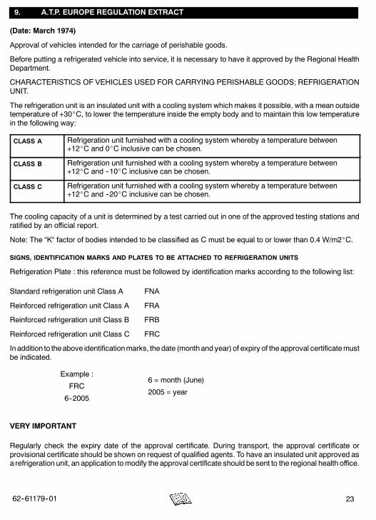
9. A.T.P. EUROPE REGULATION EXTRACT
(Date: March 1974)
Approval of vehicles intended for the carriage of perishable goods.
Before putting a refrigerated vehicle into service, it is necessary to have it approved by the Regional HealthDepartment.
CHARACTERISTICS OF VEHICLES USED FOR CARRYING PERISHABLE GOODS; REFRIGERATIONUNIT.
The refrigeration unit is an insulated unit with a cooling system which makes it possible, with a mean outsidetemperature of +30_C, to lower the temperature inside the empty body and to maintain this low temperaturein the following way:
CLASS A Refrigeration unit furnished with a cooling system whereby a temperature between+12_C and 0_C inclusive can be chosen.
CLASS B Refrigeration unit furnished with a cooling system whereby a temperature between+12_C and --10_C inclusive can be chosen.
CLASS C Refrigeration unit furnished with a cooling system whereby a temperature between+12_C and --20_C inclusive can be chosen.
The cooling capacity of a unit is determined by a test carried out in one of the approved testing stations andratified by an official report.
Note: The “K“ factor of bodies intended to be classified as C must be equal to or lower than 0.4 W/m2_C.
SIGNS, IDENTIFICATION MARKS AND PLATES TO BE ATTACHED TO REFRIGERATION UNITS
Refrigeration Plate : this reference must be followed by identification marks according to the following list:
Standard refrigeration unit Class A FNA
Reinforced refrigeration unit Class A FRA
Reinforced refrigeration unit Class B FRB
Reinforced refrigeration unit Class C FRC
Inaddition to theabove identificationmarks, thedate (monthand year) of expiry of theapproval certificatemustbe indicated.
Example :
FRC
6--2005
6 = month (June)
2005 = year
VERY IMPORTANT
Regularly check the expiry date of the approval certificate. During transport, the approval certificate orprovisional certificate should be shown on request of qualified agents. To have an insulated unit approved asa refrigeration unit, an application tomodify the approval certificate should be sent to the regional health office.
24 62--61179--01
10. 24H ASSISTANCE
At Carrier Transicold we’re working hard to give you complete service when and where you need it. Thatimplies a worldwide network of dealers and available an emergency service. These service centers aremanned by factory--trained service personnel and backed by extensive parts inventories that will assure youof prompt repair.
Should you encounter a unit problem with your refrigeration unit during transit, follow your company’semergency procedure or contact the nearest Carrier Transicold service center. Consult the directory to locatethe service center nearest you. This directory may be obtained from your Carrier Transicold dealer.
If you are unable to reach a service center, call Carrier Transicold’s 24 Hour Assistance :
In Europe, please use the following free phone numbers from :
A AUSTRIA 0800 291039B BELGIUM 0800 99310CH SWITZERLAND 0800 838839D GERMANY 0800 1808180DK DENMARK 808 81832E SPAIN 900 993213F FRANCE 0800 913148FIN FINLAND 0800 113221GB GREAT BRITAIN 0800 9179067GR GREECE 00800 3222523H HUNGARY 06800 13526I ITALY 800 791033
IRL IRELAND 1800 553286L LUXEMBURG 800 3581
RUS RUSSIA 810 800 200 31032N NORWAY 800 11435NL THE NETHERLANDS 0800 0224894P PORTUGAL 8008 32283PL POLAND 00800 3211238S SWEDEN 020 790470
From other countries or direct : +32 9 255 67 89
In Canada or United States, call 1 -- 800 -- 448 -- 1661.
When calling, please have the following information ready for fastest service :
- Your name, the name of your company, and your location.
- A telephone number where you can be called back.
- Refrigeration unit model number and serial number.
- Box temperature, set--point and product.
- Brief description of the problem you are having, and what you have already done to correct theproblem.
We will do everything we can to get your problem taken care of and get you back on the road.