operating instructions da-x · 2018. 6. 6. · safety 30 range of application 30 connecting the fgs...
TRANSCRIPT

Operating Instructions
Par
t Num
ber
AC
754
081
DA-X
Edition: 7/2002 Printing: 8/2002Language: EN

Kverneland Soest GmbHCoesterweg 42
D-59 494 Soest
Tel. +49 (0)2921 / 974-0
Identification of the machine
Your dealer requires some information about your machine in order to be able to help you as quickly aspossible. Please enter the information here.
Designation
Working width
Weight
Machine number
Accessories
Dealer's address
Manufacturer'saddress
Copyright by Kverneland Accord GmbH, Germany. No part of this manual shall be reproduced, transmitted by any means, electronic, mechanical,photocopying or otherwise, or translated without written permission from Kverneland. All rights reserved. The contents of this operating manualare subject to change without notice. The right to technical revisions is reserved.
DA-X
You can find thisdata on the typeplate

Contents
Contents
Introduction .............................................................................. 5Target group of this operating manual 5Meaning of symbols 5
Safety ........................................................................................ 6For your safety 6Warningsymbols 6Who is authorised to operate the machine? 8Coupling 8Road transport 11Putting the machine into operation 11Uncoupling 12Care and maintenance 13Further regulations 14
Familiarisation........................................................................ 15Range of application for the machine 15Features of the machine 16Assembly designation 17Technical specifications 18
Delivery and assembly .......................................................... 19
Coupling the Machinery ........................................................ 20
Hydraulic System................................................................... 21
FGS.......................................................................................... 30Safety 30Range of application 30Connecting the FGS 31Performing a calibration test 31Tramliningrhythm 32Operation 39
ESC.......................................................................................... 40Safety 40ESC connection 41Technical specifications 41Keyboard 42Calibration test with the ESC 53Electrical Seed Rate Adjustment 58Operation 61
ESA.......................................................................................... 62Safety 62ESA Connection 63Technical specifications 63Device Overview 64Overview of the Menu Structure 69Operating information 71Operator Menus 74Calibration Test 98TramliningRhythm 104Operation 108
3

Contents
Preparation Work - Drilling ..................................................109Adjusting the seed coulter pressure 110Gauge Wheel Adjustment 113S Covering Tines Adjustment 114Track Marker Adjustment 115Pre-emergence Marker Adjustment 117Shut-off valve Inspection 118Reduction head Inspection 118Metering Device Adjustment 118
Driving on the Road .............................................................124
Preparations in the Field......................................................128Ground Clearance Adjustment 128Seed hopper, loading 129Adjustments 132Inspection Tasks 132Test drive 133
Operation...............................................................................134Drilling 134Checks During Drilling 137After Drilling 138
Cleaning and Care ................................................................139
Parking and Storage.............................................................141
maintenance..........................................................................143For Your Safety 143General information 144Operational zone, ”Covering” 146Drill Technology 147Hydraulic Hoses 152Angular gear 152Miscellaneous Lubrication Points 152
Accessory Equipment..........................................................153
Eliminating Malfunctions .....................................................157
Warranty ................................................................................164
Disposal of the machine ......................................................165
EU Conformity Declaration..................................................166
Index ......................................................................................167
4

Introduction
Introduction
Target group of this
operating manual
This operating manual is directed at trained farmers and individualswho are otherwise qualified to perform agricultural activities and whohave received training in the operation of this machinery.
For your safetyBefore attempting to use or install this machinery, familiarise yourselfwith the contents of this operating manual. In this way, performanceand work safety are optimised.
As employerAll personnel are to be trained in the use of the machine regularly (atleast once a year) in accordance with employers' liability insuranceassociation guidelines. Untrained or unauthorised individuals are notpermitted to employ the machinery.
Training Your dealer will instruct you in the operation and care of the machin-ery.
Meaning of symbols In order to make this manual clear and easy to read, various symbolsare used. They are explained below:
• A dot accompanies each item in a list
� A triangle indicates operating functions, which must be per-formed
→ An arrow indicates a cross-reference to other sections of thismanual
In addition, pictograms are used to help you to find instructions morequickly:
NOTE The term, ”Note”, indicates tips and information concerning opera-tion.
The screwdriver indicates tips during assembly or adjustments.
The warning triangle indicates important safety instructions. Failureto observe these safety instructions can result in:
• Serious operational faults for the machinery;
• Damage to the machinery;
• Personal injury or accidents.
� A star indicates examples that assist understanding of the instruc-tions.
5

Safety
Safety
For your safety In this chapter you will find general safety instructions. Each chapterof the operating manual contains additional specific safety instruc-tions, which are not described here. Observe the safety instructions
• in the interest of your own safety,
• in the interest of the safety of others, and
• to ensure the safety of the machine.
Numerous risks can result from handling agricultural machines in thewrong way. Therefore, always work with special care and never underpressure.
As employerInform personnel working with the machine of these safety instruc-tions at regular intervals and according to statutory regulations.
Warningsymbols For safety purposes, stickers are provided on the machine. The stick-ers must not be removed. If stickers become illegible or begin to peeloff, new stickers can be ordered and attached in the appropriate plac-es.
StopRe-tighten all bolts after the first two hours of op-eration.
6

Safety
Meaning of the warning
symbols
Read the operating manual and follow the instructionsInitial operation of the machine must not take place before the oper-ating manual has been read and understood. This applies especiallyto safety instructions.
Do not stand between the tractor and the machineStanding between the tractor and the machine is especially prohib-ited during coupling and uncoupling and when the motor is running.The tractor must be additionally immobilised.
Riding on the machine is strictly prohibitedSerious or fatal injury can be the result.
Caution - escaping hydraulic fluidObserve the corresponding safety instructions in the operating man-ual.
Never remove the guards.Never open or remove the guards while the engine is running. Neveroperate the equipment without the guards in place.
Do not stand in the swivelling rangeThere is serious risk of injury in the swivelling range due to swivellingor folding machinery components.
Crushing hazardAvoid area of danger. Gaps between components may becomesmaller or disappear completely.
7

Safety
Who is authorised
to operate the ma-
chine?
Only qualified personnelOnly qualified persons who have been informed of the dangers as-sociated with handling the machine are permitted to operate, serviceor repair the machine. As a rule, such persons are trained and ex-perienced in agricultural work or have been thoroughly trained in asimilar fashion.
Coupling Increased risk of injuryCoupling the machine to the tractor represents an increased risk ofinjury. Therefore:
• secure the tractor in such a way that it cannot roll forwards or back-wards
• the tractor and machine must belong to the same category
• never stand between the tractor and the machine during coupling
• Slowly and carefully engage the three point power lift.
Do not connect electric wires or cables until after mounting the attachmentThe electrical supply must not be connected to the tractor whenmounting the lighting equipment.
Hydraulic connection depressurisedOnly connect hydraulic hoses to the tractor hydraulic system if thetractor and machine hydraulic system is depressurised.
High pressure in the hydraulic systemThe hydraulic system is under high pressure. Regularly check allpipes, hoses and bolted connections for leaks and externally visibledamage. Only use suitable agents when looking for leaks. Eliminatedamage immediately. Escaping fluid may result in injuries and fires.In the event of injuries, seek medical attention immediately.
Colour designation of hydraulic connectionsTo prevent operating errors, plug sockets and plugs for hydraulic con-nections between the tractor and the machine must be colour-des-ignated.
8

Safety
Observe the total weight, axle loads, tyre load-bearing capaci-ty, and minimum ballast specifications.The machine's front or rear attachment must not exceed the tractor'spermissible total weight, its permissible axle load or its tyre load-bear-ing capacity. In order for steering capability to be maintained, the frontaxle must bear at least 20 % of the tractor's empty weight.The following can be easily calculated:
• Total weight
• axle load
• tyre load-bearing capacity and
• minimum ballast
.
For this calculation, the following data is required:
Data from the tractor's operating manual:
Data from this operating manual:
Data which you can determine by performing measurements:
• (A) empty weight
• (B) front axle load
• (C) rear axle load
Make allowances for the weight of water in the tyres, accessories, etc.
• (D) Gross weight of the equipment when rear-mounted; the sup-porting load with the equipment attached;
• (E) machine's total weight in the front attachment
• (F) distance between the machine's centre of gravity in the frontattachment and front axle midpoint.
• (G) Distance between the centre of the lower link ball and the ma-chine's centre of gravity in the rear attachment. With equipmentattached, G=0.
• (H) the tractor's wheel base
• (I) distance between the rear axle midpoint and the lower link ballmidpoint
(B)Front axle load
(A)Empty weight
(E)Gross weightFront-mounting
(D)Gross weightRear-mounting
(F) (G)
(H)Wheelbase
(I)Distance between rear axle midpoint to lower link ball
(C)Rear axle load
9

Safety
Calculation The measured values can now be inserted into the formulae.
Front ballast Calculation of the front ballast for machines on the rear attachment.
Front ballast in kg =
Rear ballast Calculation of rear ballast for machines on the front attachment.
Rear ballast in kg =
Front axle load Calculation of the actual front axle load
Front axle load in kg =
Total weight Calculation of actual total weight
Total weight =
Rear axle load Calculation of the actual rear axle loadRear axle load in kg = actual total weight - actual front axle load
Tyre load-bearing capacity Data on the tyre load-bearing capacity of the front and rear wheelscan be found in the tyre manufacturer's details.
The front tyre load-bearing capacity for two wheels is equal to twicethe permissible tyre load-bearing capacity of a single front wheel. Therear tyre load-bearing capacity for two wheels is equal to twice thepermissible tyre load-bearing capacity of a single rear wheel.
Application The actual values for the rear axle load must be less than the per-missible values given in the tractor's operating manual. Tyre load-bearing capacity must be greater than the values for the rear axle loadgiven in the operating manual.
The actual total weight must be less than the permissible total weightgiven in the tractor's operating manual. If not, the machine must notbe coupled to the tractor.
NOTE If you have a sufficiently large weigh-bridge, you can determine thetotal weight and the rear axle load by weighing.
D I G )+(× B H ) 0 2 A H )××,(+×(–F H+
-------------------------------------------------------------------------------------------
E F×( ) C( H ) 0 45 A H )××,(+×–H I G+ +
------------------------------------------------------------------------------------
E F H ) B H ) D I G )+(×–×(+ +(×H
---------------------------------------------------------------------------------------
E A D+ +
10

Safety
Road transport Ensure that the machine conforms to traffic regulationsThe machine must conform to current traffic regulations if you intendto drive it on public roads. This means that, e.g.:
• lights, warning equipment and protective equipment are installed
• the permissible transport width and weight, axle load, tyre load-bearing capacity and total weight are observed.
Check the trip ropes for the quick release couplingTrip ropes must hang loose and must not, when in their lowered po-sition, release the couplings of their own accord.
No riding on the machineRiding on the machine is hazardous and strictly prohibited.
Altered driving and braking performanceDriving and braking performance are altered when the machine is at-tached to the tractor. Take the width and balancing weight of the ma-chine into consideration, especially on sharp bends.
Adjusted speedRough surface conditions and excessive speeds can generate ex-treme forces that can stress or overload the tractor and the machinematerial. Therefore, adjust your speed to the road conditions.
Putting the ma-
chine into operation
Initial operation only after training.The machine must not be put into operation until the user has beengiven proper initial instruction, either by the dealer or by one of themanufacturer's representatives or employees.
Ensure that the machine is in perfect working conditionDo not operate the machine unless it is perfect working condition.Check all important components and replace any defective compo-nents before starting the machine. Do not remove the protective equipmentProtective equipment must not be removed or by-passed. Check allprotective equipment before starting the machine.
Check tyre pressure Check tyre pressure regularly.
No riding on the machineRiding on the machine is hazardous and strictly prohibited.
11

Safety
Check immediate vicinity Before starting, extending, and during operation, check and be awareof your surroundings. Make sure the operator has a sufficient view ofthe work area. Do not begin work until the immediate vicinity iscleared of any persons or objects.
Re-tighten all nuts and boltsNuts and bolts should be checked at regular intervals and tightenedif necessary.
Action in the case of malfunctionsIn case of operational problems, immediately stop, shut down, andsecure the machinery. The malfunction may be eliminated immedi-ately, or a workshop must be commissioned.
Uncoupling Increased risk of injuryThere is an increased risk of injury when uncoupling the machinefrom the tractor. Therefore:
• secure the tractor in such a way that it cannot roll forwards or back-wards
• never stand between the tractor and the machine during uncou-pling.
• actuate the three-point power lift system slowly and carefully.
• make sure the machine is standing on a secure and level surface.
• Only disconnect hydraulic hoses if there is no pressure in the tractorand machine hydraulic system.
12

Safety
Care and
maintenance
Adhere to the care and maintenance intervals Observe prescribed intervals for maintenance checks and inspec-tions specified in the operating manual.
Use only OEM replacement parts Many components have special characteristics which are essentialfor the machine's stability and correct function. Only those replace-ment parts and accessories supplied by the manufacturer have beentested and approved. Using other products may lead to malfunctionsor reduce the safety of operation. The use of non-OEM replacementparts renders the manufacturer's guarantee null and void and releas-es the manufacturer from all liability.
For all care and maintenance work:
• switch off the tractor's power take-off shaft
• depressurise hydraulic system
• Whenever possible, uncouple the tractor;
• Make sure the unit is standing securely. Provide additional supportas required;
• do not use parts of the machine to climb onto it; use onlysecure steps, ladders or other means of access
• Chock the machinery wheels to prevent it from rolling;
• Never reach into the V-belt while it is moving.
Switch off power supplyPrior to carrying out work on the electrical system, disconnect it fromthe power supply.
Replace hydraulic hosesHydraulic hoses can age without this being externally visible. There-fore, we recommend that the hydraulic hoses be replaced every threeyears.
Caution when cleaning using a high-pressure cleanerThe machine can be cleaned using either water or a steam jet. Onlyuse a low pressure to clean bearings, fans, signal mixer units, plasticparts and hydraulic hoses.
Prior to welding work Prior to carrying out electrical welding work on the attached machine,disconnect the tractor's battery and generator.
Tighten all bolted connections All screw connections that are released during maintenance and re-pair operations must now be re-tightened.
13

Safety
Further regulations Observe the regulationsIn addition to those listed above, please observe the following safetyinstructions:
• accident-prevention regulations
• generally recognised safety regulations, occupational health re-quirements and road traffic regulations
• information in this operating manual
• regulations pertaining to operation, maintenance and repair.
14

Familiarisation
FamiliarisationThis section contains general information on your machine as well asinformation on:
• Range of application
• Features
• Designation of the assemblies, and;
• Technical specifications
Range of applica-
tion for the machine
The DA-X is seed drill designed to be saddled on power harrows. Itcan also be driven as a stand-alone device if a tractor triangle is em-ployed.
Proper use Any application other than or beyond this, e.g., as a means of trans-port, for stump pulling, or to transfer power to other objects is con-sidered improper use. The manufacturer and dealer are not liable fordamage caused by improper use. Improper use is solely at the risk ofthe user.
15

Familiarisation
Features of the
machine
Perfected typeSpecially hardened materials combined with an optimised construc-tion, a flexible modular design, and a favourable centre of gravity allmake this efficient and precision machine a reliable and sturdy de-vice.
Distributor outside the tankYou can utilize the entire tank volume, while filling is easily handled.
Precise meteringThe original Accord pneumatik system ensures precise metering.
Quick conversionConversion from norrmal to fine seed is quick and requires no tools.
Tramlining systemThe DA-X can be combined with FGS, ESC, or ESA.
CoultersNormal coulters, CX sowing coulters, or CX Plus disc coulters can beselected, based on the prevailing application conditions.
SafetyThe machine is constructed in accordance with EU and German na-tional regulations, for maximum possible safety of operation. The ma-chine bears the symbol of European Conformity (CE).
16

Familiarisation
Assembly designa-
tion
Marker disc
Seed hopper with roll-out cover
Track marker arm
Sowing coul-ter
Power harrow,shown here with cracker roller
Dispensing pan, tools, spare parts list, and operating manual are lo-cated in the seed hopper at deliv-ery.
Loading step
Drive wheel
Fan
Pressure regulation for S covering tines
S covering tines
Manual operation
Platform
17

Familiarisation
Technical specifica-
tions
General
Miscellaneous
Height (m) w./o. tractor lift height
Depending on the power harrow
Width (m)
Machinery in operating position 3,00 / 4,00 / 4,50
Depth (m)
Depending on the power harrow and equipment level
Gross weight (kg)
Depending on equipment level, approx. 900-1150
Seed hopper
Fill height (m) Depending on the power harrow
Hopper volume (l) 1000 / 1500
Maximum hopper capacity, approx. (kg of wheat) 800 / 1200
Noise level (dBa)
Fan, at 1,000 rpm 98
Tractor
Minimum towing capacity (kW) 30 KW / m
PTO (rpm)Design
10001 3/8”, 6-part
FGS, ESA, ESC
Power supply (V) 12
Fuse (A) 30
18

Delivery and assembly
Delivery and assembly
Scope of delivery Soil Preparation and Drilling TechnologyThe machine is delivered completely assembled. If parts of the ma-chine have not been assembled, please contact your dealer.
Do not assemble the machine yourselfDo not try to assemble the machine yourself, as
• the correct sequence of assembly steps and
• the observation of permissible tolerances and torques
are essential for the proper working condition of the machine.
FGS, ESA, and ESCThe tramlining control system (FGS), the electronic seed-drill drive(ESA), and the electronic seed-drill control (ESC) are also availableas optional accessories . Your agricultural equipment dealer will per-form the final installation on your tractor.
NOTE If parts are missing or have been damaged during transportation,please submit a complaint immediately to your dealer, importer or themanufacturer.
19

Coupling the Machinery
Coupling the Machinery• Never stand between the tractor and the equipment during cou-pling.
Coupling the power harrow is described in the operating instructionsfor the pneumatic seed drills. These supplemental instructions dealonly with the particular features unique to the DA-X.
PTO installation • Before working on the PTO, shut the engine off and remove the ig-nition key!
• Install only the supplied PTO or one of an identical type.
• Make sure the PTO connections lock securely in place during in-stallation.
Depending on the power harrow involved, the PTO will need to beshortened prior to installation. This task may only be performed byproperly qualified individuals.
� Loosen the locking screws.
� Pull the retainer with the fan out far enough to permit installationof the PTO.
� Install the PTO with the side on which the sliding clutch is locatedfacing towards the seed drill. The PTO must engage correctlyand be secured with the safety chains.
� Push the retainer completely in to its stop, then pull it back outapprox . 2-3 cm.
� Secure the retainer with the locking screws. Note the following:Both screws must secure the retainer.
Electrical connections Now connect the power cable for the tramlining control system (FGS),electronic seed-drill control (ESC), or the electronic seed-drill drive(ESA) and the machine’s lighting system to the tractor.
Hydraulic connections Connect the hydraulics as described in the »Hydraulic System«chapter, under »Connection to the Tractor«.
Locking screws
Retainer
PTO with sliding clutch
20

Hydraulic System
Hydraulic System• In the transport position, secure the control unit on the tractor toprevent accidental activation.
• Employing the machine with different tractors may result in in-compatible oil mixtures. Such a mixture of incompatible oils can re-sult in the destruction of tractor components.
• All hydraulic connections must be properly made and must be ex-amined for secure fit after connection.
• The fan speed may not exceed 5,000 rpm for hydraulic fan drives.
• Inspect the hoses.
Familiarise yourself
with the hydraulics.
Aside from the hydraulic connections themselves, all connections tothe ESA/ESC or FGS must also be made.
Connection to the Trac-
tor
• Only connect the hydraulics if the engine is turned off and the PTOshaft is disengaged.
• Chock the tractor wheels to prevent it from rolling!
� Connect hydraulic hoses to:
one single-acting control valve each
One double-acting control valve each
� If the hydraulic hoses to the tractor are equipped with ball valves,open all of these.
Function(single acting)
Colourcoding
• Track marker, pre-emergence marker Green
• Hydraulic fan drive(plus pressure-free return and LS withPower Beyond)
Blue
Function(double acting)
Colourcoding
• Hydraulic share bar adjustment
• Hydraulic share pressure adjustment–
Red
closed
open
21

Hydraulic System
Prior to operation, carefully inspect the hydraulic hose connectionsand the hoses themselves. Hot hydraulic fluid can squirt from insuf-ficiently tightened or damaged hydraulic hoses, resulting in severe in-jury.
Retracting the Track
Markers
The pre-emergence markers can be retracted using the hydraulichose marked in green, e.g., to avoid obstacles.
NOTE: • If an ESA is being used, the metering devices continue to operateuntil the track markers are fully retracted.
• If an ESA / ESC or FGS is being used, the tramline sequence mustbe corrected after the separate retraction of a track marker.
Hydraulic fan drive The fluid is guided to a 3-way flow control valve and regulated ac-cording to the hydraulic motor speed. This constant fluid rate resultsin a specific rotational speed of the hydraulic fan drive. This speed canbe checked on the ESA or ESC on the display.
Technical specifica-
tions
Technical specifications for the hydraulic fan drive are listed in the ta-ble.
• Speed ± 50 rpm, once the speed has levelled out at a constant oiltemperature .
Line cross-sections
Values
Hydraulic mo-tor
Displacement (ccm)Speed (rpm)
84500
Fluid supply Minimum feed line pressure(bar)Maximum return line pressure(bar)Oil flow rate (l / min)
160 10
43,5
Fan Fan speed (rpm) 4500
Feed line Return line
Line cross-section, minimumdadi
DN 1012 mm 9 mm
DN 1215 mm12 mm
Line cross-section, recommendeddadi
DN 1618 mm15 mm
DN 1618 mm15 mm
22

Hydraulic System
Prerequisites Prerequisites for the hydraulic fan drive at the tractor:
• Adequate oil supply from the tractor;
• An appropriate number of control valves are installed;
• Control valves can be activated in parallel;
• An oil cooler has been installed.
For John Deere tractors, including Series 50:
• The flow control valve must be converted from 3-way to 2-way. Re-fer to Section »For tractors without flow control valves, with controlpumps« beginning on page 24.
Types The unit can be equipped with either a
• Type 1 or
• Type 2 (configured for Power Beyond)
flow control valve.
23

Hydraulic System
Type 1 Flow Control
Valve
Fan Speed Adjustment • Prior to operation, carefully inspect the hydraulic hose connectionsand the hoses themselves. Hot hydraulic fluid can squirt from in-sufficiently tightened or damaged hydraulic hoses, resulting in se-vere injury.
• The maximum permissible fan speed is 5,000 rpm. At higherspeeds, the fan can explode.
• Wear ear protection when working near the fan.
• Conversion from a 3-way to a 2-way flow control valve, or vice ver-sa, may only be done with the fan turned off.
For tractors with flow control
valves
� Fully open the 3-way flow control valve.
� Adjust the desired fan speed by regulating the oil flow rate at thetractor.
For tractors without flow con-
trol valves, without control
pumps
� Use the adjusting screw on the 3-way flow control valve to adjustthe desired speed.
For tractors without flow con-
trol valves, with control pumps
� Convert the 3-way flow control valve to a 2-way flow controlvalve as shown in the diagram.
� Use the adjusting screw on the 2-way flow control valve to adjustthe desired speed.
Flow control valve
Type 2
Fan Speed Adjustment • Prior to operation, carefully inspect the hydraulic hose connectionsand the hoses themselves. Hot hydraulic fluid can squirt from in-
Fully open the 3-way flow control valve.
Adjusting screw
498 853
498 839
Installplate
Task number
Adjusting screw
24

Hydraulic System
sufficiently tightened or damaged hydraulic hoses, resulting in se-vere injury.
• The maximum permissible fan speed is 5,000 rpm. At higherspeeds, the fan can explode.
• Wear ear protection when working near the fan.
• Conversions from a 3-way to a 2-way flow control valve – or viceversa – and fan speed adjustment may only be done with the fanturned off.
The basic flow control valve adjustments need only be performed pri-or to initial start-up or if a different tractor is employed.
For tractors with flow control
valves
� Fully open the 3-way flow control valve.
� Adjust the desired fan speed by regulating the oil flow rate at thetractor.
For tractors without flow con-
trol valves, without control
pumps
� Use the adjusting screw on the 3-way flow control valve to adjustthe desired speed.
For tractors with flow control
valves and control pumps
The flow control valve must be converted from 3-way to 2-way. Per-form the conversion as follows:
� Loosen the locknut.
� Turn the screw fully in. Turning the crew fully in converts the 3-way flow control valve toa 2-way valve.
� Retighten the locknut.
� Use the adjusting screw on the 2-way flow control valve to adjustthe desired speed.
Fully open the 3-way flow control valve.
Adjusting screw
Lock nut
Bolt
Adjusting screw
25

Hydraulic System
Operation All hydraulic connections must be properly made and must be ex-amined for secure fit after connection.
Initial Start-up The following applies to the initial operation with oil: The fan speed will continue to change independently until the hy-draulic fluid has reached its normal operating temperature. The ad-justment is not complete until the fan speed has stabilised.
� During adjustment, continuously monitor the fan speed with therevolution counter on the ESA or the ESC. Refer to Chapter, »ESA«, beginning on page 62,or Chapter,»ESC«, beginning on page 40.
Subsequent Start-ups The following applies to all subsequent start-ups with cold oil:
• During the warm-up period, the fan speed will be somewhat higher.
• After a short time, the fan speed self-adjusts to the value set duringthe initial start-up adjustment.
Operation with Two Hy-
draulic Motors
The tractor oil supply must be adequate to permit the simultaneousoperation of two hydraulic motors. If you have previously only oper-ated with one motor, have your dealer install a parallel circuit.
26

Hydraulic System
Power Beyond The hydraulic fan drive is a continuous consumer in the hydraulic sys-tem. This means that there is frequently insufficient power availablefor other consumers. Utilization of Power Beyond allows this loss ofpower to be minimised when the hydraulic fan drive is employed asa continuous consumer so that other consumers can be activated si-multaneously. However, Power Beyond does not increase the hy-draulic pump’s conveying capacity.
• The installation must be performed by a qualified service centre.
• Conversions from a 3-way to a 2-way flow control valve – or viceversa – and fan speed adjustments may only be done with the fanturned off.
• Connections may only be made with the PTO switched off.
• Carefully inspect the hydraulic hose connections and the hydraulichoses before start-up. Hot hydraulic fluid can squirt from insuffi-ciently tightened or damaged hydraulic hoses, resulting in severeinjury.
Prerequisites Prerequisites for the Employment of Power Beyond:
• The tractor is equipped with
– Control pump,– Load sensing system,– Feed line (P),– Return line (T),– Control line (LS),– Possible leak fluid line (D)
• The machine is equipped with
– A Type 2 flow control valve (refer to page 24).
Calculating the Remain-
ing Conveying Capacity
The hydraulic pump’s conveying capacity determines the lift speed.The greater the conveying capacity, the higher the lift speed. Power Beyond allows other consumers to be activated while the con-tinuous consumer is operating, but does not increase the hydraulicpump’s conveying capacity. The lift speed drops.
EXAMPLE:
Hydraulic pump conveying capacity 100 l/min
Fluid volume required by the continuous consumer 40 l/min
Conveying capacity remaining for other consumers 60 l/min
Reduction of the lift speed to 60 %
27

Hydraulic System
Conversion to a 2-way
flow control valve
The flow control valve must be converted from 3-way to 2-way. Per-form the conversion as follows:
� Loosen the locknut.
� Turn the screw fully in. Turning the crew fully in converts the 3-way flow control valve toa 2-way valve.
� Retighten the locknut.
Use the adjusting screw on the 2-way flow control valve to adjust thedesired speed.
Connection on the trac-
tor
NOTE Depending on the make of the tractor, the couplings and connectorsmay differ. When changing tractors, please consult your dealer.
� Close the ball valve on the feed line (P).
� Connect the couplings in the following sequence:
1. Return line (T)2. Control line (LS)3. Feed line (P)
� Activate the fan speed measurement (depending on the availa-ble display device or monitor).
Lock nut
Adjusting screw
B
T
LS con-nectionP
A
A = Forward flow (feed) to the hydraulic motor B = Return flow from the hydraulic motor P = Feed T = ReturnLS = Control line
Bolt
closed
open
T
LS
P
28

Hydraulic System
Operation As a rule, the speed only needs to be adjusted prior to the initial start-up and when changing tractors. The adjustment should be checkedat the start of the season and, if the area output is large, occasionallyduring the course of the season as well.
� Open the ball valve on the feed line (P).
Only adjust the speed if the fan is stopped.
� Use the adjusting screw on the 2-way flow control valve to adjustthe desired speed.
Uncoupling � Shut the tractor engine off.
� Close the ball valve on the feed line (P).
� Disconnect the couplings in the following sequence:
1. Feed line (P)2. Control line (LS)3. Return line (T)
P
Adjusting screw
T
LS
P
29

FGS
FGS
Safety • Inspect cables prior to connection and replace any damaged ca-bles.
• The FGS will only operate reliably within the specified temperaturerange.
• Protect the switch box and plug board against moisture and dirt.
• In case of problems, immediately refer to the ”Fault Correction” ta-ble to determine whether you can correct the problem yourself. Ifnot, contact Customer Service.
• The specified operating and maintenance requirements must bemet.
• Always interrupt the power supply to the FGS during any main-tenance work. Failure to do so could result in damage to the FGS.
Range of applica-
tion
The electronic tramlining control system, FGS, allows tramlines to becreated.
Proper use The FGS is only employed in conjunction with seed drills. Any otheruse is prohibited.
Characteristics The FGS is available in 2 versions:Type 1 for rhythms: 4,5,6,7,8,9Type 2 for rhythms: 3,4S,5,6S,7,8S
The system consists of the following components:
• Switch box
• Plug board
• Cable with connectors
It also permits:
• Monitoring the hopper low level sensor
• V-belt monitoring for V-belt-driven fans
U = 12 V I = 8 A
FGS
420 048
1 2 3 4 5 6 7 8
R
hy t h m u s
4
6 7
89
5
9
30

FGS
Connecting the FGS Prerequisites
• The seed drill is equipped with shut-off or combination valves.
• The plug board has been installed on the machine and the sensorsare connected.
• The tractor is equipped with a bracket for the switch box.
� Secure the switch box to the bracket.
If the bracket has not been installed:
For tractors with cabins
� Select a suitable location that can be easily reached from theseat.
For tractors without cabins
� Install the bracket at an angle.
Plug the connectors in � Plug the connector into the appropriate socket.
Performing a cali-
bration test
As a rule, the calibration test is performed in the yard.Perform the calibration test as described in these operating instruc-tions in the Chapter, ESC, Section, »Performing a Calibration Test«,beginning on page 54.
Plug board
Retainer
Shut-off valve
Connector for con-nection to the switch box
Connector for 12 Volt socket
31

FGS
Tramliningrhythm The tramlining rhythm defines when tramlines are to be set up on thefield. The number of blocked shares is determined by the track andtyre width of the tractor you are using for fertilising and spray work. Atthe factory, all settings are set to the information you provided at thetime you ordered the machinery.
NOTE If the working width of the spraying/fertilising equipment or the trac-tor’s track width changes, please contact your dealer die.
Principals Before you can set up tramlines, it may be necessary to make alter-ations to the seed drill. This is always required if the machinery is tobe operated with a spraying/fertilising unit with a different width. Theinstallation or modification of shut-off valves is generally required. Ifthese modifications are required, have them performed before settingup the tramlines.
The tramlining rhythm is calculated from the ratio of the spraying/fer-tilising unit and the seed drill working widths.
�
The working width ratio may also result in a remainder. How the var-ious tramlining rhythms are handled is described in the »Select therhythm« section of this chapter.
Example of calculating the tramlining rhythm
Field sprayer working width 20 m
Seed drill working width; 4 m
Calculation 20/4=5
Resulting tramlining rhythm 5
32

FGS
Setting Up Tramlines Setting tramlines by blocking the shares is dependent
• on the tractor’s track width;
• the width of the spraying/fertilising unit, and;
• the row width.
The tractor track width can be dimensioned so that the tractor tyres:
• Drive over the centre of a seed row, or;
• Drive between two seed rows.
Use the graphic in conjunction with the table. The following apply:
• A = Drive over the centre of a seed row.Please note: Select the number of blocked shares so that the tractortyres do not drive over any seed row.
• B = Drive between two seed rows,Please note: Select the number of blocked shares so that the tractortyres do not drive over any seed row.
NOTE For particularly wide tyres, you will need to block several adjacentshares to set up the tramline.
The table lists possible spraying/fertilising unit track widths depend-ent on the row width.
A = centre
B = between
Row width[cm]
Seed drill width [m]with (no. of shares)
Spraying/fertilising tractor track width [m]
A B A B A B A
11,1 4 (36) 1,41 1,50 1,59 1,69 1,78 1,88 1,97
10,3 6 (58) 1,34 1,43 1,55 1,65 1,75 1,86 1,96
12,5 6 (48) 1,38 1,50 1,63 1,75 1,80 2,0 –
15,0 6 (40) 1,35 1,50 1,65 1,80 1,95 2,10 –
33

FGS
Calculate the Rhythm The table is merely intended as an overview. The table lists some ofthe most common tramlining rhythms fro the seed drill as dependenton the spraying/fertilising unit working width (m), e.g., field sprayers,fertiliser spreaders.
overview
Common tramlining rhythms
Working widthSpraying/fertilising unit
(m)
Working widthSeed drill (m)
4,00 4,50 6,00
12 3 – 2
16 4 – –
18 4,5 4 3
20 5 – 3,3
24 6 5,3 4
27 – 6 4,5
28 7 – –
30 7,5 – 5
32 8 – –
36 9 8 6
34
FGS
The following chart contains several examples of tramlining rhythms.
5
2
2
531
1 2 3 4 5
621
21 3
3
6s 6
Rhythmus B/A
3
B
5 4
4s 4
4 1 4
6
321
B12
A
3 4
B 8
A = SowingB = Fertilising / sprayingB/8 = of the working width of the sprayer, 1/8 or 1/2 the working width of the seed drillB/12 = of the working width of the sprayer, 1/8 or 1/2 the working width of the seed drill
Numbers on the left = tramlining rhythm
35

FGS
Example of a tramlining rhythm with a remainder:18 m spraying/fertilising unit4 m seed drill
Start at the right edge of the field
Start at the left edge of the field
23R567L89101112L13141516R17181
9m18m18m18m9m
4 1
4m
4m
Field-edge
Drilling
Fertilising/spraying
2
4m
3L 4 5 6 7R 8 9 10 11 12R 13 14 15 16L 17 18 11
9m 18m 18m 18m 9m
4m
Field-edge
Drilling
Fertilising/spraying
36

FGS
Select the rhythm The rhythm is dependent on the working width of the seed drill and thespraying/fertilising unit. It may be
• uneven, or;
• even, or;
• symmetrical, or one(with an ”S” after the number, indicating symmetry),
• a special rhythm.
The type of rhythm affects the set up of tramlines.
NOTE As an additional, optical indicator, the diode goes on when tramlinesare being set up.
Uneven Rhythms 3, 5, 7, 9, 11During a single drive, the tramline is always set up symmetrically. Youcan begin cultivation on the right or left side of the field.
Even Rhythms The tramline is set up during two drive passes. The side of the fieldat which you must start depends on which side the shut-off valves onyour seed drill are mounted (left or right) and on the rhythm with whichyou intend to work.
4, 8, 12Start on the same side of the field as the side on which the shut-offvalves are mounted.
6, 10, 14Start on the side of the field opposite to the side on which the shut-off valves are mounted.
If you start on the wrong side of the field, the spraying/fertilising equip-ment will not fit in the tramlines.
NOTE Setting up the tramlines in two drive passes means that the individualtracks cannot be set up as precisely as with a single drive pass. How-ever, with even rhythms, the tramlines can be set up in a single drivepass. You machinery must be set up for this at the factory. → Section»Symmetrical Rhythms«, page 38.
Setting up the tramlines dur-ing a single drive
Setting up the tramline in two drive passes
37

FGS
Symmetrical Rhythms Z. B. 2S, 4S, 6SSymmetrical rhythms compensate for the disadvantage of evenrhythms, i.e., having to make two drive passes. Symmetrical rhythmsare additionally identified by an ”S”. During the first drive at the startof the field you must turn off half the working width. The machinerymust be set up at the factory for symmetrical rhythms.
� Turn off half the working width and begin drilling on the corre-sponding side of the field. This pass is not counted in the tram-line sequence. A flashing triangle above the associated symbolbelow the display provides a visual indication that the width hasbeen turned off.
� On the return pass, drill with the full working width. This is pass”1” in the tramline sequence. Do not drive in the track markertrack, but along the boundary of the surface cultivated in the firstpass.
If you fail to turn half the working width off during the initial pass or youdo not drive along the boundary of the cultivated area on the returnpass, the spraying/fertilising equipment will not fit in the tramlines.
Special Rhythms Special rhythms result from a poor ratio of seed drill working width andsprayer/fertiliser equipment working width. The machinery must beset up at the factory for special rhythms.
The side of the field on which you must begin working depends onworking width of both the seed drill and the sprayer/fertiliser.
If you start the first pass on the wrong side of the field, the spraying/fertilising equipment will not fit in the tramlines.
38

FGS
Adjusting the Tramline
Rhythm with the FGS
� Using a screwdriver, adjust the desired rhythm.
� Unfold the track marker on one side. On the field, the side onwhich the return pass will be made should unfold.
� Using the button, advance the pass once until diode ”1” goes onfor the test pass.
Operation Seed drilling in conjunction with the FGS is described in the »Oper-ation« Chapter, Section »Drilling«.
U = 12 V I = 8 A
FGS
420 048
1 2 3 4 5 6 7 8
R
hy t h m u s
4
6 7
89
5
9
Pass indication by diodes
Type 1:Pass indication
Type 2:Tension monitor
Hopper low level sensor and V-belt monitoring
Tramline be-ing set up
Rhythm adjust-ment
Button to advance the pass
39

ESC
ESC
Safety • Inspect cables prior to connection and replace any damaged ca-bles.
• The ESC only operates reliably in the specified temperature range.
• In case of problems, immediately refer to the ”Fault Correction” ta-ble to determine whether you can correct the problem yourself. Ifnot, contact Customer Service.
• The specified operating and maintenance requirements must bemet.
• Always interrupt the power supply to the ESC during maintenancework. Damage to the ESC may otherwise occur.
Range of application The Electrical Sower Controller (ESC) provides economical seed dis-tribution.
Proper use The ESC is only used in conjunction with seed drills. Any other useis prohibited.
Characteristics The ESC regulates and controls the essential drilling functions of theseed drill using signals and input data. In addition, the ESC also as-sumes important control functions, such as:
• Travel-dependent control of the metering devices;
• Monitoring the fan speed, the hopper level, the metering devices,the drive wheel
The system consists of the following components:
• Computer;
• Signal distribution box
• Sensors
It also permits:
• The adjustment of the optimum amounts of seed;
• The start of seeding in inaccessible areas;
• Tramlines;
• Half-width shut-off;
• Metering device monitoring;
Onboard computer The onboard computer in the tractor cab is used to input and monitorseeding values. In conjunction with the sensors, faults are automat-ically detected and an acoustic alarm signal is generated.
40

ESC
Signal distribution box This represents the link between the onboard computer and the sen-sors. It is mounted on the machinery frame.
Sensors A travel sensor determines the distance travelled. It is mounted on thedrive shaft.
ESC connection Prerequisites
• The ESC and the connecting sockets are completely and properlyinstalled on the tractor
� Connect the cable.
Technical specifica-
tions
Power supply cable2-pin
Controlcable
ESC
Power supply (V) 12
Fuse (A) 16
Temperature range (°C) -10 to +60
41

ESC
KeyboardThe ESC keyboard contains:
• Operating keysto switch the unit on and off;
• Control keysgreen keys to activate functions;
• Information Keyswhite and yellow keys to call up information during operation;
• Input keysyellow and white/yellow keys to input, save, and delete machinerydata.
The following sections explain the meanings of all the symbols on thekeyboard and the display.
Symbols On the Key-
board
The ESC is easy to operate by means of keys. This section provides all the information concerning the symbols onthe keyboard for the:
• Operating keys
• Control keys
• Information Keys
• Input keys
42

ESC
Operating keys The operating keys switch the ESC
ON (green key)
or
OFF (red key)
Control keys
(green)
The control keys are used to implement functions. These keys controlthe
• Half-width shut-off / Stop shut-off;
• Seed rate adjustment
• Seed rate adjustment cancellation;
• Tramlining rhythm adjustment.
Half-width shut-off / stop shut-off of the left-side metering de-vice If two metering devices are being used, this key switches the one onthe left side off (half-width shut-off). The ”off” state is indicated by a
triangle above the symbol on the display.. Switching
the metering device off interrupts the hectare count.
NOTE If only a single metering device is being used, this key switches it onor off as required (stop shut-off).
Half-width shut-off, right side metering deviceThis function can only be used if there are two metering devices at-tached. Press the key to switch the metering device on the right sideon and off as required. The ”off” state is indicated by a triangle
above the symbol on the display..
NOTE If only a single metering device is being used, this key is inactive.
Seed rate adjustmentThis input increases the original seed quantity / ha in percentagesteps (increased output).
A triangle above the symbol on the display indicates
that a seed rate adjustment has been made.The prerequisite for seed rate adjustment is the adjustment of the set-ting screw on the metering device. This adjustment procedure is de-scribed in a separate section.
+%
43

ESC
Cancelling the seed rate adjustmentThis key is used to readjust the seed rate to its original value, withoutincreased output.
NOTE: • Corrections can only be made if the drive wheel is turning.
• Keys and can only be sequentially
pressed after a 10 second delay.
Tramlining rhythm adjustmentThe current tramline is manually advanced by one track. Necessary
• To set the correct starting position;
• In case of accidental tramline advance during operation, e.g., asa result of lifting the machinery over obstacles
NOTE The desired tramline can only be set by advancing the track. The trackcannot be decreased.
Information Keys
(white and white/yellow)
These keys to call up information during operation. Information isavailable about:
• Cultivated area, in ha;
• Total cultivated area per season;
• Currently cultivated area, in ha/hr.;
• Current fan speed;
• Operating hours;
• Working speed, in kph;
At the same time information concerning
• Working speed, in kph;
• Current fan speed;
• Currently cultivated area, in ha/hr.;
is shown, the display also indicates the tramline.
NOTE While this information is displayed you can use the green control keyto advance the tramline by one track. The change is indicated by ahorn sound and the display of the new tramline.
+1
44

ESC
Cultivated area, in haThis key calls up information concerning the cultivated. Measurementautomatically stops when the machinery is at rest.
Total cultivated area, e.g., per seasonDisplays the total area cultivated.
Current area performance, ha/hr.This key calls up information concerning the current area perform-ance, in ha/hr. Measurement automatically stops when the machin-ery is at rest.
Current fan speedDisplays the fan speed in rpm.
Operating hoursThe following functions are available:
Read operating hours
� Press the key once
Use stopwatch function
� Press the key twice: Clock stops.Press the key again: Timekeeping restarts.
Timekeeping stops and starts automatically when the computer isswitched on.
Working speed, in kphIndicates the speed during seeding.
kg/ha
kg/ha
45
ESC
Input keys
(yellow and white/yellow)
The input keys are used to display and modify machinery data.
• Display current settingsby pressing the associated key.
• Input new valuesusing the arrow keys.
• Save new valuesusing the ”Enter Input” key.
• Exit the display by pressing the delete key.
Tramlining rhythmDisplays the stored tramlining rhythm and the tramline.
Working widthIndicates the machinery working width.
Number of pulses / 100 mDisplays the number of pulses measured over 100 m.
Arrow keysUse the arrow keys to change the current values. Pressing and hold-ing an arrow key will continuously change the display until the key isreleased.
NOTE
Save new or modified values with – otherwise the new set-
tings will be lost.
Enter InputSaves the changed value.
Delete keySeveral functions:
• Deletes values entered in the display;
• When used in conjunction with other keys, its function changes, asdescribed in more detail in the following section.
46

ESC
Key combinations with All combinations involving the ”Delete” key initially result in the mem-ory being cleared. Combinations with a dual function will also activatea process.
Dual function combinations
”Cultivated area, in ha” and ”C”Two functions
• Resets the cultivated area in ha memory to zero
• Starts the calibration procedure for normal metering.This function can only be utilised if the ”metering device monitoring”accessory has been installed.
NOTE Preparation for the normal calibration procedure and the calibration test are described in a separate section.
”Cultivated area, in ha” and ”C”Two functions
• Resets the area performance in ha/hr. memory to zero
• Starts the calibration procedure for micrometering This function can only be utilised if the ”metering device monitoring”accessory has been installed.
NOTE Preparation for the micrometering calibration procedure and the calibration test are described in a separate section.
Single function combinations
”Enter Input” and ”C”
Resets the and memories to zero.
”Total hs” and ”C”Deletes the complete total ha memory for the entire area cultivatedduring the season.
”Pulses /100 m” and ”C”Deletes the.pulses/100 m memory. Resets the memory and begins counting pulses again as soon as thedrive wheel begins turning.
”OFF” and ”C”Resets all memories to zero.
kg/ha
kg/ha
kg/ha
47

ESC
Saving the fan speed The maximum permissible fan speed is 5,000 rpm!
Before saving, the seed drill must be driven at the nominal PTOspeed. Once the PTO speed has been reached, the following fanspeeds can be selected for your seed drill:
NOTE The speeds are identical for both mechanical and hydraulic fandrives.
� Press the key with the machinery running.The current speed is displayed..
� Press the key.The displayed fan speed is saved.
Working width adjust-
ment
The seed drill working width must be provided in order to correctly setup tramlines and to calculate area performance.
PTO speed [rpm]
Fan speed[rpm]
1000 4500
→ or →
48

ESC
Adjusting the tramlining
rhythm
The tables and setup diagrams for the tramlining rhythm can be found in the section, »3You now specify the rhythm for your machin-ery vis the ESC.«.
Travel sensor calibration The travel sensor receives one pulse for each rotation of the drivewheel. In order to assign a specific number of pulses to a distancetravelled, the travel sensor must be calibrated. There are two optionsfor doing this:
• Drive along a path that is exactly 100 m long, or;
• Read the values from the table and store them.
Driving a path � Before starting and while still standing still, delete the ”Pulses/
100 m” stored in memory.
� Drive exactly 100 m then press the key to save the indi-
cated number of pulses.
Saving table values The values given in the table depend on the circumference of yourseed driller’s drive wheel and on the soil conditions. The actual soilconditions may result in different values. Calibration by means of ac-tually driving across the field is more accurate.
� While standing still, delete the ”Pulses/100 m” stored in memory.
� Enter the desired value from the table.
� Save.
→ or →
Working width (m)
Drive wheel Pulses/100 m
4.00 Star wheel 42
4.50 Star wheel 42
49

ESC
Display The display shows the various symbols and their related numbers.
Symbols on the display provide information about:
• Operating conditions;
• Machinery settings
• Fault
Numbers on the display provide information about:
• Machinery data
• Tramline position
Symbols at the bottom of the display provide information about:
• Current machinery settings;
• Alarms
NOTE Some of the display symbols only appear when you are actually work-ing with the ESC.
Symbols on the display Arrow, circle, and triangle indicate different operating conditions, ma-chinery settings, and faults.
Arrow
Switching the ESC on brings up an arrow on the display. The ESC isnow operational.
Circle
A flashing circle below the arrow indicates that the drive wheel is turn-ing. The machinery is in its operating position.
Triangle Triangles on the display always appear in conjunction with the sym-bols at the bottom of the display. The triangles indicate machinery set-tings or, if they are flashing, indicate faults.
• Reference triangles = Display of current machinery settings
• Flashing triangles = Display faults
NOTE The symbols at the bottom of the display are explained in the sub-sequent sections.
50

ESC
Numbers on the display
Operating data This contains all the information you can call up by means of the whiteor white/yellow keys.
Machinery data Contains all the information you can call up with yellow keys
Tramline position The number after the vertical dotted line indicates the current tramlineposition. When a tramline is set, this number flashes.
Symbols at the bottom of
the display
The symbols at the bottom of the display are associated with the ref-erence and flashing triangles and provide information about:
• Current machinery settings;
• Fault
Machinery settings A triangle above the symbol indicates the current machinery settings.
Right side (rear) metering device switched off.
Left side (front) metering device switched off.
Seed rate adjustment set to increased output.
Alarms Alarms may be generated during operation or when the ESC isswitched on. Visually, they are indicated by flashing triangles abovethe symbols at the bottom of the display.
• Hopper low level alarm
• Fan speed alarm
• Metering device drive alarm
NOTE: • Alarms cannot be manually activated.
• Generation of an alarm also produces an acoustic warning.
+%
+%
+%
51

ESC
Hopper low level alarmA triangle flashes above the hopper level symbol on the display. In ad-dition, a horn sounds every 2 seconds to provide an acoustic alarm.
• Hopper reserves in use
• Residual quantity in the hopper below minimum level
The alarm switches off when the hopper is refilled.
Fan speed alarmA triangle flashes above the fan speed symbol on the display. In ad-dition, a horn sounds every second to provide an acoustic alarm.
• The fan speed has dropped 10% below the saved lower fan speedlimit.
• A drop in fan speed can result in seed blocking the seed deliverytubes.
The alarm switches off once you increase the fan speed.
Metering device drive alarmA triangle flashes above the metering device drive symbol on the dis-play. In addition, a horn sounds at given intervals to provide an acous-tic alarm.If the metering device drive is interrupted for longer than 5 secondsduring stop or half-width shut-off, a triangle flashes above the fanspeed symbol on the display. In addition, a horn sounds 5 times afteroperation is restarted to provide an acoustic alarm
• The metering device drive has been interrupted.
The alarm switches off once the problem has been corrected.
+%
+%
+%
52
ESC
Calibration test
with the ESC
General The calibration test is essential for optimum cultivation. The prereq-uisites for performing a calibration test include:
• All required data must be entered.
• For seed drills equipped with a metering device,– turn off the second seeding shaft (right-hand metering device).
• For seed drills equipped with two metering devices, – turn the second seeding shaft on.
Please note the following before starting the calibration test:
NOTE: • The calibration test can only be performed if the machinery is re-tracted and the tractor and PTO shaft are switched off.
• For seed drills with two metering shafts, the calibration test startswith the left (front) metering device.
• To avoid inaccuracies, perform a calibration test with each me-tering device.
• Perform a new calibration test every time you change seed type.
• The factory-defined default value for the micrometering system is”ON”. Change these settings only when you wish to operate withnormal metering.
+%
+%
53

ESC
If you are working with normal metering you must switch microme-tering for the seed drill off as described in the chapter, »PreparationWork - Drilling« , beginning on page 121..
NOTE However, the micrometering system on some seed drills is extremelydifficult to access. In this case, bypass the deactivation:
• Leave the micrometering system turned on.
• Enter a larger setpoint value than indicated at the metering device.
• Perform one or more calibration tests for comparison purposes.
The micrometering must only be switched off at the seed drill if thequantity of fine seed being sown is more than 15% below that desiredwith the metering device fully opened, as explained in chapter, »Prep-aration Work - Drilling«, section, »Micrometering off«, page 121.
Performing a Calibra-
tion Test
• For the calibration test, the machinery must be in the transport po-sition, with wheels chocked to prevent rolling, and sides securedagainst extension.
• Inspect the seed hopper for foreign objects.
If you are using two metering devices, you must perform the calibra-tion test on each one.
Before you can begin the calibration test:
� Close the auger emptying flap on both metering devices.
� Place the red locking tap in the ”Fine” or ”Normal” seed position.
� Place a catch pan under the metering device. The catch pans must be large enough to hold the seed generat-ed during the calibration.
� Open the hopper emptying flaps.
Auger emptying flap
Red locking tap –Shown here in the
Hopper emptying flaphopper emptying flap
54

ESC
Now use the ESC to prepare the calibration test.
You must use the correct adjustment value for your particular seed inorder to perform the calibration test. → »Preparation Work - Drilling«,section. »Determine the adjustment value«, page 119.
� Read the adjustment value for normal or fine seed from the ta-ble.
For example, the adjustment value in the table is 50 mm.
� Using the handle, adjust this value at both metering devices. Ad-justing to this value changes the metering device cell width.
NOTE There must be no seed in the metering device if you are decreasing
the cell width.
� Add sufficient seed to the hopper for the calibration test.Please note: The hopper low level sensor in the seed hoppermust be covered by at least 3 cm of seed.
� Remove the calibration handle from its retainer.
� Pull the shaft off and mount the calibration handle on the shaft.Secure with a cotter pin.
The seed drill is now ready for the calibration test. Perform the cali-bration test according to the machinery settings for normal or mi-crometering.
Handle
Scale
Pull the shaft off,mount the cali-bration handle, and secure it.
Calibration han-
55

ESC
Normal metering For normal metering, the calibration test is performed for 1/10 ha.
� press simultaneously.
� Carry out 85 revolutions with the calibration handle mounted onthe metering device. With metering device monitoring: A hornwill sound after 85 revolutions.
Micrometering For micrometering, the calibration test is performed for 1/10 ha
� press simultaneously.
� Carry out 86 revolutions with the calibration handle mounted onthe metering device. With metering device monitoring: A hornwill sound after 85 revolutions. Continue for one additional revo-lution.
kg/ha
kg/ha
56

ESC
Calibration test evalua-
tion
NOTE: • The calibrated quantity of seed represents the amount sown for 1/10 ha.
• We recommend performing the calibration test at 1/10 ha for sow-ing quantities up to approx. 100 kg/ha, and at 1/20 ha for largerquantities. At 1/20 ha, halve the number of revolutions.
At the conclusion of the calibration:
� Close the hopper emptying flaps.
� Combine the seed from both metering devices and weigh it.
Failure to close the hopper emptying flap will result in the seed fallingdirectly on the ground during sowing, and not being passed to theseed coulters.
NOTE: • The quantity of calibrated seed does not necessarily correspondto the value in the table. One reason for this is the difference in thethousand grain weight.
• For deviations in the seed quantity:
� Convert the difference to the quantity in the table into %.
� Correct the adjustment at the metering device up or down by thispercentage. When doing this, make sure there is no seed in themetering device if you are decreasing the cell width.
Close the hopper emp-tying flap.
57
ESC
Electrical Seed Rate
Adjustment
Electrical seed rate adjustment is only suitable for normal seeding.Once set, the additional seed quantity can easily be added or shut offvia the ESC.
Before starting work you must:
• Set the base quantity (100 %);
• Set the desired additional quantity (+ x%);
• Adjust the adjusting setting screw
• Check the additional quantity by running a calibration test.
NOTE The metering device cell width can be increased by a maximum of 20mm when using the seed rate adjustment.
Base quantity The base quantity is the amount of seed you wish to apply per ha. Youhave previously performed the adjustment on both metering devicesand have checked them by performing a calibration test.
� Adjust the base quantity at the metering device.
The ESC is now switched to a base quantity = 100 %.
� If necessary, repeat the calibration test as described in the pre-vious chapters.
Set the additional
quantity
Determine the additional quantity adjustment value as follows:
�
→
Additional quantity calculation example
For a seed quantity ofBase setting at the metering de-vice
100 % 50 mm cell width
Desired additional quantity + 10 %
Calculation 50 mm x 10 % /100
Result:Additional quantity adjustmentvalue
+5 mm cell width
After switching on the seed rate adjustment
55 mm, new cell width
58

ESC
NOTE: • Maximum cell widthDo not exceed a maximum cell width of 110 mm for the base setting+ cell width for the additional quantity.
Adjust the adjusting
setting screw
Now set the calculated value for the additional seed at the adjustingsetting screw on the seed rate adjustment.
� For this example, set the adjusting setting screw for seed rateadjustment to 5 mm on the scale.
NOTE: • Do not exceed the maximum cell width of 110 mm, including theseed rate adjustment.
• Increasing the cell width After the adjusting setting screw has been adjusted and the elec-trical seed rate adjustment is switched on, the cell width is auto-matically increased to the specified value.
Checking the addition-
al quantity
After adjusting the adjusting setting screw, check whether the addi-tional quantity is actually being output.
� Press.
� Fill the hopper.
� Use to switch on the additional quantity..
� perform a calibration test.→ in this chapter, section, »Calibration test with the ESC«, be-ginning on page 53
3You now specify the rhythm for your machinery vis the ESC.Use the following key combination for the spraying/fertilising unitwidth:
Use the following key combination for the tramlining rhythm:
A number appears on the display. The following table indicates which
Adjusting setting screw for seed rate adjustment
→ or →
→ or →
59

ESC
number is assigned to which tramlining rhythm.
Number on the dis-
play
Rhythm Start on which side of the field?
0 No tramline2 2 Any3 3 Any4 4 Any5 5 Any6 6 Any7 7 Any8 8 Any9 9 Any10 10 Any11 11 Any12 12 Any14 14 Any
Symmetrical rhythms2-5 2-S Any4-5 4-S Any6-5 6-S Any8-5 8-S Any
10-5 10-S Any12-5 12-S Any
Rhythms with remainders15 15m/8m and 20m/6m Right16 15m/8m and 20m/6m Left18 18m/4m Left19 18m/4m Right20 20m/6m and 10m/3m Left21 20m/6m and 10m/3m Right22 18m/12m Left23 18m/12m Right24 24m/4.50m Left25 24m/4.50m Right26 27m/6m Left27 27m/6m Right28 28m/8m and 21m/6m Left29 28m/8m and 21m/6m Right30 30m/4m Left31 30m/4m Right
54, 55, 60, 61,
141,181Not applicable to seed drills
60

ESC
Operation Drilling in conjunction with the ESC is described in the »Operation«chapter, section, »Drilling«.
61

ESA
ESA
Safety • Inspect cables prior to connection and replace any damaged ca-bles.
• The ESA only operates reliably in the specified temperature range.
• Always turn the RPM alarm on during drilling, otherwise the me-tering device can start while the fan drive is off.
• In case of problems, immediately refer to the ”Fault Correction” ta-ble to determine whether you can correct the problem yourself. Ifnot, contact Customer Service.
• Always interrupt the power supply to the ESA during maintenancework. Damage to the ESA may otherwise occur. Area of application
The Electrical Sower Drive (ESA) provides economical seed distri-bution in conjunction with satellite navigation systems.
Proper use The ESA is only used in conjunction with seed drills. Any other useis prohibited.
Characteristics The ESA regulates and controls the essential drilling functions of theseed drill using signals and input data. A large number of these sig-nals activate and drive the metering device. Among other things, ESAregulates the speed of the metering shaft during drilling, while alsoperforming important control functions, such as:
• Travel-dependent control of the metering devices;
• Monitoring the fan speed, the hopper level, the drive wheel, thespeed.
It also permits:
• Calibration problems to be stored;
• The adjustment of the optimum amounts of seed;
• The start of seeding in inaccessible areas;
• Tramlines;
• Half-width shut-off;
• Metering device shut-off;
• Checks of sensors and motors.
62

ESA
ESA Connection Prerequisite: The ESA and the connecting sockets are completelyand properly installed on the tractor.
� Connect the cable.
Technical specifica-
tions
ControlcablePower supply cable
Supplemen-tary control-cable
ESA/ESC
Power supply (V) 12
Fuse (A) 30
Temperature range (°C) -5 to + 50
63

ESA
Device Overview
Keyboard The ESA keyboard contains
• Keys with a fixed function,e.g., symbol keys, numeric keys
• Variable function keys
The following sections explain the meanings of all the symbols on thekeyboard and the display.
Variable function keys
Return
InfoContrast
Memory
Hold
Delete
Light
64
ESA
Symbols On the Key-
board
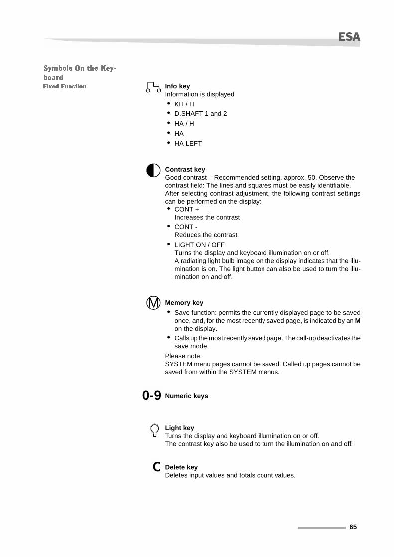
Fixed Function Info key Information is displayed
• KH / H
• D.SHAFT 1 and 2
• HA / H
• HA
• HA LEFT
Contrast keyGood contrast – Recommended setting, approx. 50. Observe the contrast field: The lines and squares must be easily identifiable.After selecting contrast adjustment, the following contrast settingscan be performed on the display:• CONT +
Increases the contrast
• CONT -Reduces the contrast
• LIGHT ON / OFFTurns the display and keyboard illumination on or off.A radiating light bulb image on the display indicates that the illu-mination is on. The light button can also be used to turn the illu-mination on and off.
Memory key
• Save function: permits the currently displayed page to be savedonce, and, for the most recently saved page, is indicated by an Mon the display.
• Calls up the most recently saved page. The call-up deactivates thesave mode.
Please note:SYSTEM menu pages cannot be saved. Called up pages cannot besaved from within the SYSTEM menus.
Numeric keys
Light keyTurns the display and keyboard illumination on or off.The contrast key also be used to turn the illumination on and off.
Delete keyDeletes input values and totals count values.
M
0-9
C
65

ESA
Variable Function Function keyThis allows
• Set values to be displayed;
• Make selections in the menu.
Return keywith several functions:
• Confirms inputif no ”OK” button appears on the display for confirmation;
• Moves you back to the previous display;
• Permits status displays to be shown after input;
• Moves you to an additional display after all information has beenprinted.
Display Please note:Sometimes the display symbols are not immediately visible and onlyappear when you are actually working with the ESA.
Symbols on the Display
With an information function
• Operating speed
• Mileage
• Supply voltage
• Drilled seed amount
• Remaining seed in the hopper
• Metering shaft speed
• Seed rate adjustment
• Manual tramline sequencing
• Fan speed
• Metering device(s) ON/OFF
• Cultivated area
• Area performance
• Remaining area
• Stopwatch
• Calculated completion time
• Time
• Date
66
ESA
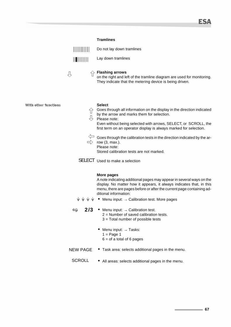
Tramlines
Do not lay down tramlines
Lay down tramlines
Flashing arrowson the right and left of the tramline diagram are used for monitoring.They indicate that the metering device is being driven.
With other functions SelectGoes through all information on the display in the direction indicatedby the arrow and marks them for selection. Please note: Even without being selected with arrows, SELECT, or SCROLL, thefirst term on an operator display is always marked for selection.
Goes through the calibration tests in the direction indicated by the ar-row (3, max.). Please note:Stored calibration tests are not marked.
Used to make a selection
More pagesA note indicating additional pages may appear in several ways on thedisplay. No matter how it appears, it always indicates that, in thismenu, there are pages before or after the current page containing ad-ditional information:
• Menu input: → Calibration test. More pages
• Menu input: → Calibration test. 2 = Number of saved calibration tests.3 = Total number of possible tests
• Menu input: → Tasks: 1 = Page 16 = of a total of 6 pages
• Task area: selects additional pages in the menu.
• All areas: selects additional pages in the menu.
SELECT
2/3e.g.
NEW PAGE
SCROLL
67

ESA
Miscellaneous
Confirm input or display status.
Sets up a new calibration test.Please note: If 3 calibration tests already exist, one of the existing ones will be over-written when you save a new calibration test.
Menu system: Used for sensor checks for pulse queries.
Flashing HOLD on the displayDepending on the operation sensor selected, a flashing HOLD canhave the following affects:
• For the ”DRILL.” operation sensor:Metering device drive stops.
• For the ”NONE” operating sensor:Metering device drive continuous running.
OK
NEW CALIB.
HI und LO
= HOLD
68

ESA
Overview of the
Menu Structure
The following pages provide and overview of the ESA menu structure.
KM/HMETERAKKU
KGKG LEFTDRILL SHAFT* %- %DOSERATEMANUEL STARTTRACK * 1TRACK - 1RPM
GO ON DRILL
NORMAL
LEFT STARTRIGHT START
NORMAL SEED
HA/HHAHA REST
TIMER STARTENDTIMECLOCKDATA
TIMER STOP
OPERATING
INPUT
(task))
DATA DELETESYSTEM
Status display
See next page
ESA on
69

ESA
INPUT
(Task)
DATA/DELETE
SYSTEM
WORKING WIDHTSTEP %CALIB. PROCED.CALIB. TESTKG RESTHA REST
RYTHMUSNUMBER OF ROWSROWS IN TRACKSEED RETURNTRAVEL SENSOR
OPERAT. SENSOR
WORK HOURON/OFF
WARNING ENCODE
DATE/CLOCK
NEW CALIB. SEED RATEWORKING SPEEDSELECT CROP
SAVE CALIB. 1SAVE CALIB. 2SAVE CALIB. 3
START 1/10 HASTART 1/20 HA
CULTIVAT. IMPLEM.WIDTH
START LEFTSTART RIGHT
WHEEL DRILL
RADAR
CALIB. CALC
CALIB. CALC
CALC.
CALC.
3-POINT DIN ISO3-POINT EXTERNDRILLNONE
OPERAT. SENSORMANUEL
KM/HKG RESTD. SHAFTHOPPERRPMGRAIN WARNING
HOURSMINUTESSECONDSYEARMONTHDAY
FILL CELL
STARTSTART TASK KEY IN ID NO.STOP TASK START TASK
PRINT TASK
WEIGHTCALC.
DELETEANULL.
DELETEDELETE TRIP
TEST INPUTSTEST OUTPUTSLANGUAGED. SHAFTGPS-SYSTEMSYSTEM DATA
PRINT ONEPRINT ALL
70

ESA
This chapter contains
• Operating information
• Operator menus
• Tramlining rhythm
• Calibration test
• Operation
Operating informa-
tion
Turning on the ESA In order to subsequently operate the ESA, make sure it is properlyconnected with:
• A control line;
• A line from the signal distribution box to the ESA;
• Three-prong plug-in connection to the tractor supply voltage.
� Switch the PTO shaft off.
� Switch the ESA on.
Alarms The ESA first tests the connected electronic surroundings. While thistakes place, you may receive one of the alarm messages shown here,accompanied by an audible alarm.
The upper or lower working speed limit violated. Enter new values viathe keyboard. Delete by pressing ”C”.
The remaining seed in the hopper has dropped below the defined re-sidual limit. Add seed or enter a new KG LEFT value.
Indicates that the metering shaft is no longer turning. Check whethera second metering shaft has been turned on, even though you onlyuse a single one. In this case, deactivate the second metering shaft.HOPPER
Remaining seed in hopper now below the specified minimum level.Add seed or enter a new KG LEFT value.
Start-up from the console
KM / H
KG LEFT
D. SHAFT
Hopper re-serves be-ing used.
71

ESA
Currently not available.
Upper or lower fan speed limits violated.Specify and enter a fan speed for seeds. Maximum speed: 5,000 rpm;minimum speed: 3,500 rpm. Under no circumstances may the actualspeed go above or below this range. Too slow a speed can result inseed clogs in the seed delivery tubes.
Always turn an RPM alarm off prior to the calibration test, otherwisethe system cannot perform the desired test.
Always turn the RPM alarm on during drilling. If the alarm is notswitched on metering device can start while the fan drive is off.
Alarm Function
Deactivation
You can deactivate all the alarms from the same menu in order to workwith the computer without being interrupted by alarms.
� First, confirm the displayed alarms with ”OK”.
� Then turn the alarms off with
� Repeat this sequence for each alarm.
NOTE The hopper or grain alarm are part of the accessory equipment pack-age. If these accessories are not installed, but the alarms have beenactivated, an acoustic alarm will sound. In this case, deactivate thesealarm functions.
After switching the alarms off, use the RETURN key to return to thestarting menu.
Alarm Function
Activation
Do not switch the alarms you feel you may need on until you havecompleted your data input.
GRAIN
RPM
→ Input → SCROLL → Alarm input → SELECT → ON / OFF
72

ESA
Messages If your data input was incorrect, one or more error messages will ap-pear on the display. They will be accompanied by an acoustic alarm.
� Check you input and make the necessary corrections.
The actual seed value is too small compared to the setpoint.
Remedy:
� Use the calibration test to recalculate the seed quantity. → be-ginning on page 99.
� Stay within the calculated speed range during operation.
Application rate too high or too low.
Remedy:
� Determine the correct application rate from the table, then enterthis value. The calibration test calculations will determine thecorrect cell width. → beginning on page 99.
� Depending on the information from the ESA:Turn the micrometering system on or off. The factory-defined de-fault value for the micrometering system is ”ON”.
The specified tramline/rhythm combination is not possible.
Remedy:
� Check the settings. → beginning on page 79.
� Select a suitable combination.
There may be two reasons for this message:
• The second metering device has been activated, although you areusing only one.
Remedy:
� Turn the second metering device or shaft off.→ beginning onpage 96.
Work rate exceeded. →
Calculated cell width illegal. →
Combination not possible. →
Dose rate exceeded or insufficient. →
73

ESA
Operator Menus The operator menus:
• Operation
• Input
• Tasks;
• Delete data;
• System;
are already familiar to you from the overview. In the following sectionsthey are explained in greater detail under:
• General InformationHere you will find an overview of the selected menu.
• Symbols and TermsDuring processing, symbols and terms appear on the display.These are listed and explained in the table.
• Practical ExampleThe practical examples provide task descriptions, then offer a quickoverview to show you the shortest path to the displays in which youcan make the necessary settings. This quick overview also employs the terms, ”Symbol Display” and”Operator Display”, that are explained below.
NOTE Entries for tramlining rhythm or calibration tests are given after thepractical example for the ”SYSTEM” menu item.
Symbol dis-play
Display view after switching on the ESA with the symbols
Operator dis-play
Display view after the symbol display and containing the individual menus:OPERATIONINPUT
(task)DATA / DELETESYSTEM
74

ESA
Operation
General Information This provides you with an overview of:
• Information regarding tractor performance during operation;
• Individual seed drill functions;
• Information concerning the area performance;
• Time and date.
Symbols and Terms This table explains the symbols and terms you will encounter in the”OPERATION” menu. Continuously recurring symbols and terms are explained on page 65.
Dis
pla
y sy
mb
ols
Information regarding tractor performance
Selectable
Seed drill functions
Area performance
Time and date
KM / H Working speed
DisplayMETRE Mileage, in meters
BATT Supply voltage to the computer
75

ESA
KG Amount of seed drilled, in kg (calculated)
DisplayKG LEFT
The amount of seed remaining in the hopper can only bedisplayed if you filled the hopper before beginning workand entered the initial amount of seed.
D.SHAFT
• Displays the metering shaft speed, in rpm;
• Monitors the metering shaft speed and generates analarm if the speed exceeds or drops below the spec-ified value, if the alarm is activated.
Alarm activation / deactivationMenu
ENCODE → alarm input →metering shaft
turn on or off
+ % - %Incremental increase or reduction of the specifiedamount of seed / hectare, in % increments.
Activate
NORMAL
Only displayed after an incremental increase or de-crease of the amount of seed. Information in % incre-ments flashes during the display.To reset the increase or decrease, press the key. Thenormal (original) value is then redisplayed.
Activate
SEED RATE
This function only appears if no incremental increase ordecrease in the specified amount of seeds has takenplace in & increments.The amount of seed is shown in kg / hectare, but onlychanges if continue sowing with the same type of seed.If you cannot operate in the specified sowing speedrange, perform a new calibration test. If you are not working with the same type of seed:
• Perform a new calibration test, or;
• Call up the appropriate, stored calibration test.
Enter
Perform
Sowing speed rangeMin. and max. km / hr shows the speed range duringsowing. Within this range, the ESA automatically regu-lates the metering device drive.
View
MANUEL START
Starts sowing immediatelyeven if you cannot deploy the seed drill prior to the startof sowing. This function is useful in corners or near ob-stacles.Note: Wait for a few seconds before driving to compen-sate for seed feed to the shares, but start driving within20 sec., otherwise the metering device drive will bestopped.Once the drive speed signals begin to arrive, automaticregulation begins and the display switches to ”MANUALSTOP”.
Activate
MANUAL STOPStops the metering device drive. This display only ap-pears if the ESA is receiving drive speed signals.
ActivateLEFT START Start the front metering device.
RIGHT START Start the rear metering device.
Flashing ALL STOP Both halves of the seed drill are switched off. View
Flashing LEFTflashing RIGHT
Information indicating which side of the seed drill wasnot switched off.
View
76

ESA
TRACK +1
TRACK -1
The current tramline is manually advanced or de-creased by one track. Necessary
• To set the correct starting position;
• In case of accidental tramline advance during oper-ation, e.g., as a result of lifting the machinery over ob-stacles
Switch
RPM
Fan speed, in rpm.Monitors the fan speed and generates an alarm if thespeed exceeds or drops below the specified value, if thealarm is activated.
• Change the fan speed in the menu: ENCODE → alarm input →RPM
• In the same menu: Alarm activation / deactivation
Display
Enter
turn on or off
GO ON DRILL
If activated ahead of obstacles:
• The track marker can be raised;
• The metering device drive continues running;
• The tramline track is not advanced;
• Display switches to ”NORMAL DRILL”
• ”HOLD” flashes in the lower display area.
Activate
G on the displayBoth track markers have been retracted. The electricmotor is switched off. Metering stops.
Display
Flashing HOLD
Refers to the incremental increase in the tramline track.Turn on or off
• with the old key on the keyboard, or
• by selecting and switching off ”NORMAL DRILL”.
Turn on or off
NORMAL DRILLThe function to incrementally increase the tramline trackis switched off.
Deactivate
HA / H Area performance per hour.Display
HA Currently cultivated field area.
HA LEFT
Area remaining to be cultivated.This display is only possible if you entered the size of thefield area before beginning sowing.Menu
ENCODE → HA LEFT
Display
Enter
TIMER Stopwatch that can be manually started and stopped. Display
END TIME
Calculated time current operation will be concluded.”END TIME” can only be displayed ifInformation concerning HA / H and HA LEFT is availa-ble.
Display
CLOCKDATE
• Current time
• Current date
Both can be changed in theMenu
ENCODE → CLOCK / DATE
Display
Enter
77

ESA
Practical Example The ”Tractor”, ”Area”, and ”Clock” menus are self-explanatory, thepractical example will therefore confine itself to the area of the seeddrill.
You would like to determine the sowing speed range in which youneed to operate if you use a different amount of seed (e.g., 50 kg / hec-tare).
NOTE The sowing speed range changes as dependent on the specifiedamount of seed.
If you cannot operate in the indicated sowing speed range, performanother calibration test. → Chapter »Performing a Calibration Test«page 99.
ENCODE
General Information Here you enter data required to control the metering device drive.Save the individual entries with the Return key.You can display the status of your input after each entry by pressingthe Return key. This allows you to check that all the values you haveentered are correct.Calibration test and determination of the tramlining rhythm are de-scribed in detail in a separate chapter, using a practical example in the”SYSTEM” menu.
Symbol display → → SCROLL
-0%
SCR-OLL
SEEDRATE
+0%
TRACK-NO
1 6
OK
50.0 KG / HA
SEEDRATE
OK
SPEEDRATE
2.3MIN
SEED APPLI-CATION
KG / HA
D. SHAFT
0 0
XXXMAX
KM / H
11.3
KM / H
78

ESA
Symbols and Terms This table explains the symbols and terms you will encounter in the”ENCODE” menu. Continuously recurring symbols and terms are explained beginningon page 65.
”EN
CO
DE
” d
isp
lay
WORKING WIDTH Enter the seed drill working width in cm. Enter
STEP IN %
The entry produces an incremental increase or de-crease of the specified amount of seed in% increments.The increments are identical for both ”+ %” and ”- %”.In case of an incorrect setting, an error message indi-cating that the operating range has been exceeded isgenerated (motor operating outside the speed range).In this case, entered values are no longer considered forthe operation.
Enter
CALIB. PROCED.
After selection, you can use the follow-on menus to:
• Define the settings for the calibration test;
• Display stored calibration tests;
• Perform a new calibration test.
The calibration test can only be performed if there is asufficient amount of seed in the seed hopper.Note: The calibration test is described after the ”SYS-TEM” menu.
Select
Dis
pla
y th
e st
ore
d c
alib
rati
on
tes
t
Display the seed type You can read the selected seed type here.
View
KG / HADisplays the kg / hectare value determined during thecalibration test.
KM / H Displays the input performance / hour.
CELLDisplays the cell width (adjustment value) determinedby the calibration test, in mm. This is the value you setat the metering device.
FINENORMAL
Input specifying fine or normal seeds.
MICMETRE ONMICMETRE OFF
Indicates whether the micrometering system at the me-tering device is turned on or off.
1 / 3
The information differs depending on whether and howmany calibration tests you have saved.1 = Number of saved tests3 = Total number of tests
NEW CALIB.After selection, you can use the follow-on menus to en-ter the settings for a new calibration test.
Call up
79

ESA
Dis
pla
ys a
new
cal
ibra
tio
n t
est
SEED RATE Amount of seed, in kg / hectare. Enter
WORKING SPEEDEnter the average speed with which you wish to work. orconfirm the default setting.
Enter or confirm
SELECT CROPThis calls up a list of seed crops from which you can se-lect the desired type of seed. If your particular seed isnot listed, select one with similar characteristics.
Select
SET VALUE MMDisplays the calculated setpoint value for the meteringdevice. Set this value at the metering device.
Confirm
DRILL READY The seed drill is ready for the calibration test. Display
FILL CELLConfirming this prompt starts the metering device andfills the cells.
Confirm
Flashing WAIT Flashes until the procedure is finished.
START 1 / 10 HAStarts the calibration test with 1 / 10 hectare of the areato be calibrated.
Start
START 1 / 20 HAStarts the calibration test with 1 / 20 hectare of the areato be calibrated.
PAUSE Interrupts the calibration test.Activate
RESTART Continues the calibration test.
WEIGHT GRAMME Enter the seed weight of the sample. Enter
Flashing CALC.Calculates the sowing speed range and displays themin. and max. km / hr values.
Activate
SEED APPLICATION SPEEDDisplays min. and max. km / hr. after you enter the seedweight of the sample and perform the calculation.
Display
SAVE CALIB1SAVE CALIB2SAVE CALIB3
Saves the values from the respective calibration test.After saving, the test can be called up viaMenu
ENCODE → CALIB. PROCED.
Activate
Dis
pla
ys t
he
calib
rati
on
tes
t
CALIB. TEST
This test simulates a cultivation procedure using all thecurrently set and calculated values. Here you can checkwhether the amount of seed at the start agrees with theamount of seed determined by the calibration test.
Select
TEST CALIBRATIONAREA:
Enter the area to be used for the test, e.g., 0.1 hectare.The amount of seed corresponding to the area must becaptured.
Enter
START Starts the test of the calibration test. Start
DONE Test completed. Confirm
”EN
CO
DE
” d
isp
lay
KG LEFT
The amount of seed remaining in the hopper, in kg, canonly be displayed if you filled the hopper before begin-ning work. Enter theamount of seed, in kg, here. Whenrefilling the hopper, take the remaining seed in the hop-per into account.Example To calculate ”KG LEFT”100 kg remaining in the seed hopper, 400 kg added =500 kg left
Display
Enter
80

ESA
”EN
CO
DE
” d
isp
lay
HA LEFT
Displays the area still to be drilled. Calculates the difference between the area alreadydrilled and the total area. The remainder is the HA LEFT.The area to be cultivated is entered in this menu.
Display
Enter
RHYTHM
After selection, you can use the follow-on menus to:
• Define the settings for the calculation of the tramlin-ing;
• Specify that cultivation is to begin on a specific sideof the field;
• Display the information for the rhythm calculation aswell as the results of the calculation.
Note: The tramlining rhythm is described in greater de-tail after the ”SYSTEM” menu.
Select
Dis
pla
ys t
he
rhyt
hm
CULTIVAT IMPLEM. WIDTH
This is required in order to calculate the tramliningrhythm and set up the tramlines. Input in cm. Entering ”0” = No tramlines will be set up.
Enter
VALVE LEFTThe blocked share is in the left portion of the seed drill.Start cultivation on the right side of the field.
Confirm
VALVE RIGHTThe blocked share is in the right portion of the seed drill.Start cultivation on the left side of the field.
Confirm
SYMMETRICAL
After selecting, new display with the information enteredto this point and the tramlining rhythm, follwed by an ”S”for symmetrical. Tramlines are set up during cultivation.
Select
START LEFTSTART RIGHT
Cultivation starts on the left side of the field.Cultivation starts on the right side of the field.After selection, a new display showing the current in-formation and the calculated tramlining rhythm ap-pears.
Select
Confirm
”EN
CO
DE
” d
isp
lay
NUMBER OF SHARES Enter the number of shares on your seed drill. Enter
SHARES IN TRACKThe number of shares in each track to be locked out forthe purpose of tramline marking.
Enter
SEED RETURN
Return of seed to the seed hopper.Prerequisite for this recirculation:
• Shut-off valves with seed return function are in-stalled;
• The diffuser tube is in the seed hopper.
Deactivate the return function if:
• Shut-off valves that operate both with and withoutseed return are installed in your seed drill;
• The seed from blocked shares is to be distributed toadjacent shares.
SelectActivate
Deactivate
TRAVEL SENSORThe travel sensor measures the distance travelled in thefield.
Select
81

ESA
Dis
pla
ys t
rave
l sen
sor.
WHEEL DRILL Travel pulses are generated by the drive wheel.
CM / IMP.Enter the cm of travel per pulseunder ”WHEEL DRILL.” CALIBRATE
Enter
RADAR Equipment currently not available.
PULSES / M Number of pulses per meter
CALIBRATE
After confirming, you can use the follow-on menus to:
• Enter CM / PULSE, or;
• Have CM / PULSE calculated. The number of pulsesis incremented.
Enter
Dis
pla
ys t
rave
l sen
sor.
Flashing CALC. WHEELActivate at the end of the 100 m long travel path.Calculate CM / PULSE.
Activate
NO. OF PULSES
Displays:
• During travel:The incrementing number of pulses;
• Upon stopping after 100 m:The total number of pulses measured over this dis-tance.
View
DRIVE 100 MCalibration instruction: ”Drive exactly 100 m.”
DRIVE
”EN
CO
DE
” d
isp
lay
OPERAT. SENSORSelect the type of operation sensor.
Select
Op
erat
ion
sen
sor
typ
es
3-POINT EXTERNAL
Prerequisite: The external operation sensor must be installed.This selection is only required if:
• The seed drill is not equipped with track markers;
• No signal from the signal socket is available.
3-POINT DIN / ISO
Prerequisite: The tractor is equipped with a DIN / ISOsignal socket.The metering device is controlled via the DIN / ISO sig-nal socket.
DRILL Control via track marker changeover mechanism.
NONE
Selection only required if the track marker changeovermechanism cannot be controlled via sensors.Note: Fahrgassenschaltung Then use ”Rhythm+” and”Rhythm-” to manually set the tramline.
”EN
CO
DE
” d
isp
lay
WORKHOUR ON/OFF
Measures the sowing time, taking into account the op-eration sensor or a manual switching die. Display of themeasured sowing time under:
→ TIMER
Select
Enter
82

ESA
Dis
pla
y ti
mer
OPERAT. SENSOR Measures only the sowing time.
SelectMANUAL
Measures the total time required for rotating, driving,turning, and sowing.
”EN
CO
DE
” d
isp
lay
ALARM DISPLAYIn this menu, you can turn alarms on and off, as de-scribed in more detail beginning on page 71.
Turn on or off
DATECLOCK
Display or change the current date and time. DisplayEnter
83

ESA
Practical Example You want to set the operation sensor first, then the travel sensor.
Operation Sensor Setting: The table above contains information concerning the individual sen-sors.
You have selected NONE
• even though a sensor is installed on the track marker changeovermechanism. The NONE function is deactivated and the tramliningrhythm when the track marker is changed over will continue to beautomatically incremented, just as if you had selected DRILL.
• even though your machinery is equipped with a wheel sensor. Withthis combination, the ESA automatically switches to the DRILL op-eration sensor. The information appears in the operation sensordisplay.
• because there is no sensor installed on the track marker change-over mechanism. Please note:The tramlines will not automatically switch. In this case, you mustmanually enter the change in the tramlining rhythm.
Operator dis-play → INPUT → OPERAT. SENSOR → SELECT
NONE
OPERAT. SEN-SOR
SENSORDIN / ISO
NONE
LIFTDRILL
SENSORNONE
84

ESA
Manually Change the Tramlin-
ing Rhythm
In the example, the rhythm was increased from 2 to 3. The tramlineis set up at 3 (black line on the tramline diagram).
Symbol display → → SCROLL
TRACK+1
SCROLL
TRACK-1
MANUALSTART
TRACK+1
SCROLL
TRACK-1
MANUALSTOP
TRACK-NO
3 6
TRACK-NO
2 6
KG / HA
XXX
180 KG / HA
XXX
180
85

ESA
Travel Sensor Setting Depending on how your seed drill is equipped, you can use either asensor on the seed drill drive wheel or a wheel sensor to measure thedistance travelled on the field. In order to obtain precise measure-ments, you must first calibrate the sensor. There are two options fordoing this:
• Use the keyboard to enter the previously calculated value for CM/ PULSE;The table lists the most common values for CM / PULSE and thenumber of pulses generated by the sensor on the drive wheel aftertravelling a distance of 100 meters.
• Or make an actual test drive on the field.
NOTE The calculated values do not apply to radar sensors.
NOTE However, the table data will result in imprecision on difficult terrainsince the actual field conditions (e.g., slipping, rough ground) was nottaken into consideration. Determing the values by means of a test drive is more accurate as thistakes the actual field conditions into account.
Drive wheel Approx. value of
CM / PULSE
Approx. number of pulses after a distance of 100
m.
MSC / KLX / DA / DA-S / DE-S / DF / DG / DA-X
14,0 714
7.00-12 (DL) 11,8 850
26.00-12.00 (DL) 12,0 833
7.50-16 (DT) 14,3 697
31-15.50 (DT / DV / DC) 13,7 731
86

ESA
The example is for the calibration of sensor at the drive wheel with theaid of a test drive.
� Mark a precisely 100 m long path on the field you will be cultivat-ing.
� Drive to the starting point.
� Call up the calibration menu.
� Start the calibration (2nd display) when you start driving.
� Stop at the end of the marked stretch.CALC. WHEEL flashes on the display.
� Calculate CM / PULSES (3rd display).The calculated value is displayed (4th display).
Operator dis-play → INPUT → TRAVEL SEN-
SOR → SELECT → WHEEL DRILL → CALIBRATE
CALIBRATE CALIBRATE
CALC.WHEEL
CALIBRATE CALIBRATE
X,X CM /
WHEELDRILL
X,X CM / NO. OFPULSES
WHEELDRILL
X,XCM / PULSE
714
NO. OFPULSES
WHEELDRILL
14,0CM / PULSE
WHEELDRILL
DRIVE 100METRE
DRIVE 100METRE
87

ESA
TASKS
General Information The ”TASKS” task administration function is practical for entrepre-neurs who are paid on a ”by job” basis. For each task saved, it pro-vides an overview of:
• The size of the area cultivated;
• The amount of seed applied;
• The cultivation time.
and permits
• Task identification by either an ID no, or an order number;
• From 1 to 35 tasks to be saved and recalled.
With the appropriate accessory equipment, you can transfer the taskdata to your computer for further processing, or print them out directlyto an attached printer. Information concerning accessories availablefor the ESA is given in Chapter »Accessory Equipment« beginningon page 153.
Symbols and Terms This table explains the symbols and terms you will encounter in the”TASKS” menu. Continuously recurring symbols and terms are explained beginningon page 65.
In this menu, the Return symbol performs three functions:
• Confirming inputs;
• Moves you back to the previous display;
• Moves you to an additional display after all information has beenprinted.
TA
SK
S
Indication that a task is running
View
Generally stands for tasks that can still be assigned.
DRILL. 1 Previously saved tasks with numbering
TASK 34
Tasks that can still be assigned, with numbering.
88

ESA
Ter
ms
on
th
e d
isp
lay
KEY IN ID NO. Opens the TASK ID NO. display Activate
TASK ID NO.Enter a code number (up to 8 characters), e.g., the cus-tomer or personnel number, etc.
Enter
TASK STOP Interrupts a running task. Activate
SEE TASK
Provides two functions without starting a task:
• First, displays the current task;
• Pressing the key a second time displays the statusof the current task.
Display
START TASK Select a task, then start it.
START
• New task selected: ”START” starts the new task.
• Previous task selected: ”START” continues the pre-vious task, even if it has not been completed.
• Previous task completed with ”STOP . TASK”: callingthe previous task up again and pressing ”START”cancels the ”STOP . TASK” command and continuesprocessing the previous task.
SelectStart
TASK DELETE Displays the task to be deleted and deletes it. Activate
PRINT TASK
Switches you to the print menu and offers the followingselections:
• ”PRINT ONE”
• ”PRINT ALL”
Activate
PRINT ONEThe selected task is displayed. Prints the selected task. Prerequisite: A printer is con-nected and ready.
Activate
89

ESA
Ter
ms
on
th
e d
isp
lay
Prints the task.After printing (printing task) automatically returns you tothe print menu.
View
PRINT ALL
Selected tasks are not displayed. Prints all tasks. Prerequisite: A printer is connected andready.
Activate
Prints all tasksMakes the tasks available to the printer (printing alltasks), then automatically returns you to the print menu.
View
Using the Return key, you can access the delete menuwith the following selections:
• ”DELETE”
• ”CANCEL”
Note: This menu can only be accessed after all taskshave been printed.
Activate
DELETEThis menu only allows you to delete all tasks. Individualtasks cannot be deleted here.
Activate
CANCEL Cancels the print order. Activate
NEXT PAGE35 tasks are filed on 6 pages. Use ”NEXT PAGE” to se-quentially page through all task pages.
Activate
90

ESA
Practical Example You want to set up two tasks with task numbers, view the tasks, thenprint them.
Setting Up the First Task .
The first task is assigned the ID no. ”007”. The zeros are not shownon the display.
Working with the task and
ending the task.
Press to return to the operator display. . indicates thata task is currently. If you do not wish to set up another task, start thisone and begin drilling. Once drilling has been completed, completethe first task.
Operator dis-play →
STARTTASK
NEXT PAGE
START
TASKSTOP
TASKDELETE
SEETASK
INPUTID NO.
TASK
TASK 2
TASK 4
TASK 3
TASK
TASKID NO. 7
TASK 6
1/6
TASK 5
35 0
TASK 1TASK 1
007
TASKSTOP
TASKDELETE
SEETASK
INPUTID NO.
TASK
NO. 1
TASKTASK
TASKDELETE
SEETASK
INPUTID NO.
TASK
34 1
91

ESA
If you wish to continue an existing task, the computer adds the valuesfor kg and hectares to the existing values. With the start of a new task,the count for this task starts at ”0”.
Setting Up the Second Task .
Complete the second task in the same way as the first.
Display Task Before starting cultivation, you can call up all saved tasks and viewthem sequentially without starting or printing them.
Operator dis-play →
TASKTASK
TASK:DELETE
SEETASK
STARTTASK
NEXT PAGE
START
TASKSTOP
TASKDELETE
SEETASK
INPUTID NO.
TASKTASK 4
TASK 3
TASK
TASKID NO. 815
TASK 6
1/6
TASK 5 NO. 2
34 1
TASK 1DRILL. 1TASK 2
0815
Operator dis-play → → SEE TASK → Mark a
task → SEE TASK
92

ESA
Print Tasks
After preparation for printing (”printing all tasks”), the most recentlyprocessed task is marked. You can now mark each task you wish toprint, or print all tasks. Pressing the Return key once all tasks have been printed takes youto the display in which you can delete all the printed tasks.
→ TASKTASK → PRINT
TASK
STARTTASK
TASK
35 0
CANCEL
DELETE
PRINTTASKS
DELETE
1/1
PRINTPRESS
ONTASK
DRILL. 2
DRILL. 1
PRINTING
TASKSPRINT
93

ESA
DATA / DELETE
General Information The ”DATA / DELETE” offers you the option of deleting the all or se-lected data from the most recent cultivation work. The data relate to:
• Time;
• Area;
• Distance;
• The amount of seed applied;
for the most recently cultivated field. Prerequisite: The data were reset (”zeroed”) prior to the start of cul-tivation.
You can also view summarized data (data totals with a ”+” after TIME,HA, METRES, KG) from the previous pass here, but can only deletethem individually.
NOTE This is the only menu in which you can view total data.
Symbols and Terms This table explains the symbols and terms you will encounter in the”DATA / DELETE” menu. The information applies to the start of the ze-ro setting. All values identified by a ”+” are values from the total coun-ter.Continuously recurring symbols and terms are explained beginningon page 65.
Ter
ms
on
th
e d
isp
lay
TIME Field data for the working time
Select
TIME + Total count of the working time
HA Field data for the cultivated area
HA + Total count of the cultivated area
METRE + Distance travelled, in meters
KG Field data for the amount of seed applied
KG + Total count of the amount of seed applied
DELETE
Deletes the value in the display.The display is not visible while a task is running. Stop thetask in order to bring up the display and to allow the taskto be carried out.
Activate
DELETE TRIP
Deletes all the values for the most recent trip. Totalledvalues remain intact, and can only be deleted individu-ally.The display is not visible while a task is running. Stop thetask in order to bring up the display and to allow the taskto be carried out.
Activate
94

ESA
Practical Example You want to delete the value for meters from the total counter .
.
SYSTEM
General Information You can perform the following settings in the ”SYSTEM” menu:
• Select the display language;
• Activate a second metering shaft;
• Check the function of sensors and actuators;
• Switch the GPS on.
You can only switch the GPS satellite navigation system on if the as-sociated electronic equipment (module) is installed.
NOTE Additional menu functions are for the use of service technicians.
Operator dis-play → SCROLL → DATA / DELETE
DELETE TRIP
DELETE
TIME +8:32:47
HA +32:14
HA2:80
TIME52:10
KG420
METRE +48644
KG420
METRE +48644
TIME +8:32:47
HA +32:14
HA2:80
TIME52:10
KG420
TIME +8:32:47
HA +32:14
HA2:80
TIME52:10
METRE +
DELETE TRIP
DELETE
DELETE TRIP
DELETE
95

ESA
Symbols and Terms This table explains the symbols and terms you will encounter in the”SYSTEM” menu. Continuously recurring symbols and terms are ex-plained beginning on page 65.
TEST INPUTS
Used to locate faults in sensors and actuators with theaid of the diagnostics display. HI and LO, together withthe change of pulse states indicate whether the sensoris even receiving pulses.
Select
Inp
ut
test
dia
gn
ost
ic d
isp
lays
WHEEL. IMPLEMENT
Sensor functional tests.View
RADAR
MOTOR 1MOTOR 2
DRILL SHAFT 1DRILL SHAFT 2
MOTOR 1 Check of drive motor 1 Activate
MOTOR 2 Check of drive motor 2 Activate
TRACK MARKER
Sensor functional tests.
GRAIN WARN., currently not available.
View
SENSOR
FAN
HOPPER SENSOR 1HOPPER SENSOR 2
GRAIN WARN. 1GRAIN WARN. 2GRAIN WARN. 3GRAIN WARN. 4
TEST OUTPUTSUsed to locate faults in sensors or actuators on shut-offvalves or drive motors with the aid of the diagnostics dis-play.
Select
Ou
tpu
t te
st d
iag
no
stic
dis
pla
ys
OUT 1OUT 2OUT 3OUT 4
Sensor functional tests. View
POT 1POT 2
Tests the metering device drive potential when OUT 2 orOUT 4 is activated.
View
OUT 1 Tests the shut-off valve(s) on the left.
Activate
OUT 2
Tests motor 1.When the motor is running, the value at the OUT 2 sen-sor constantly changes. This checks the pulse gener-ator. If the value does not change, the pulse generatormay be defective.
OUT 3 Tests the shut-off valve(s) on the right.
OUT 4
Tests motor 2.When the motor is running, the value at the OUT 4 sen-sor constantly changes. This checks the pulse gener-ator. If the value does not change, the pulse generatormay be defective.
LANGUAGE Select the display language. Select
D. SHAFT Activate or deactivate the second metering shaft. Turn on or off
GPS SYSTEMActivate or deactivate the GPS System. If the module isnot installed, a module prompt will appear on the displayif you attempt to activate the GPS system.
Turn on or off
SYSTEM DATA Only for the use of service technicians.
96

ESA
Practical Example You would like the display information to appear in your native lan-guage.
.
Operator dis-play → SCROLL → SYSTEM → LANGUAGE
SELECT
TESTOUTPUTS
D. SHAFT
TESTINPUTS
SYSTEMDATA
SELECT SELECT
LANGUAGE
SVENSKA
DANSK
FRANCAIS
ENGLISH
TESTOUTPUTS
D. SHAFT
SYSTEMDATA
HOLLANDS
DEUTSCH
TESTINPUTS
LANGUAGE
97

ESA
Calibration Test
General The calibration test is essential for optimum cultivation. The prereq-uisites for performing a calibration test include:
• All required data must be entered.
• For seed drills withone metering device – turn the second seeding shaft off;two metering devices– turn the second seeding shaft on.
Please note the following before starting the calibration test:
NOTE: • The calibration test can only be performed if the tractor and PTOshaft are switched off.
• For seed drills with two metering shafts, the calibration test startswith the left (front) metering device.
• To avoid inaccuracies, perform a calibration test with each me-tering device.
• Perform a new calibration test every time you change seed type.
• If the desired type of seed is not shown in the ESA seed list, selectone with similar characteristics.
• The factory-defined default value for the micrometering system is”ON”. You can only change this setting if you receive the infor-mation, ”MICMETER OFF” on the display.
In this case, you must turn the micrometering system off at the seeddrill as explained in the Chapter, »Preparation Work - Drilling« be-ginning on page 121. However, the micrometering system on someseed drills is extremely difficult to access. In this case, bypass the de-activation:
• Leave the micrometering system turned on.
• Enter a larger setpoint value than indicated at the metering device.
• Perform one or more calibration tests for comparison purposes.
Only if the sowing quantity for fine seed drops below the desired valueby more than 15% with the metering device fully opened will you needto turn off the micrometering on the seed drill as described in theChapter, »Preparation Work - Drilling«, Section. »Micrometeringoff«, page, 121.
Operator dis-play → INPUT → WORKING WIDTH
Operator dis-play → SYSTEM → D. SHAFT → SELECT → ON / OFF
98

ESA
Performing a Calibra-
tion Test
• For the calibration test, the machinery must be in the transport po-sition, with wheels chocked to prevent rolling, and sides securedagainst extension.
• Inspect the seed hopper for foreign objects.
If your unit is equipped with two metering devices, perform the cali-bration tests sequentially for both metering devices.
Before you can begin the calibration test:
� Close the hopper emptying flaps on the metering device.
� Place the red locking tap in the ”Fine” or ”Normal” seed position.
� Add sufficient seed to the hopper for the calibration test. Please note: The hopper low level sensor in the seed hoppermust be covered by at least 3 cm of seed.
� Place catch pans under the metering devices. The catch pans must be large enough to hold the seed generat-ed during the calibration.
� Open the hopper emptying flaps.
Now make the necessary settings via the ESA.
In the subsequent displays, either accept the indicated default valueswith ”OK”, or enter:
• The amount of seed, in kg / hectare
• The working speed, in km / hr.For example, based on your experience, the speed ranges be-tween 10 and 15 km / hr.
� Enter, for example, 12.
Then
� Select the seed from the display.
Red locking tap –Shown here in the
Operator dis-play → INPUT → CALIB. PRO-
CED. → SELECT → NEW CALIB.
99

ESA
Once you have selected the seed type, the display showing the cur-rent settings for the metering device appears.
The calculated setpoint value is, for example, 53 mm.
� Using the calibrating handle, set this value at both metering de-vices. Only modify the micrometering system settings if explicitlyasked to do so by the ESA.
The seed drill is now ready for the calibration test, starting with thefront (left-hand) metering device.
� Start the calibration test with 1 / 10 or 1 / 20 hectare.
OK
NORMALSEED
VALUE MM 53
SET
WHEAT
ONMICMETER
Handle
Scale
OK FILLCELL
START1 / 20 HA
START1 / 10 HA
START1 / 20 HA
START1 / 10 HA
NORMALSEED
VALUE MM 53
SET
WHEAT
DRILLREADY
SIDELEFT
GRAMME
WEIGHT 0
ONMICMETER
100

ESA
NOTE For sowing volumes up to approx. 100 kg / hectare, we recommendperforming the calibration test at 1 / 10 hectare. For higher sowing vol-umes, use 1 / 20 hectare.
After starting the cell wheel turns at the previously set speed. ”WAIT”flashes on the display.
Pause � Interrupt the test with ”PAUSE”, e.g., to change catch pans.
� Deactivate ”PAUSE ” with ”RESTART”.
At the conclusion of the calibration:
� Close the hopper emptying flaps.
� Weigh the seed.
NOTE The amount of seed generated during the calibration does not cor-respond mathematically to the to quantity to be expected for 1 / 10 or1 / 20 hectares. For the calibration test, the ESA specifies a specificnumber of rotations for the metering device, regardless of the area.Only after the test of the calibration test results will the metering de-vice distribute the amount of seed corresponding to the area.
� Enter the weight of the weighed seed, in grams.
� Select ”CALC.”.The sowing speed range for the calibration test is displayed.
� Confirm with OK.Permits cultivation to be carried out with the determined valueswithout saving them.
NOTE We strongly recommend performing a test of the values determinedby the calibration test. →, page 102.
Save Calibration Test You can also save all input and calculated values for the current cal-ibration test. Up to three calibration tests can be saved.
� Save the calibration test.
Hopper emptying flap
101

ESA
Variations 1. You want to work with the values of a previously saved calibra-tion test:
� Call up the calibration test
� Set the values at the seed drill.
2. You want to work with the values of a previous calibration test,but want to change the sowing quantity:
� Simply enter the new quantity, do not recalibrate.
� Set the values at the seed drill.
Performing a Test of
the Calibration Test
Results
With this test you can check whether the amount of seed in the catchpans corresponds to the desired amount of seed.
� Lower the track marker arm.
� Place catch pans under the metering devices and open the hop-per emptying flaps.
� Enter an area for the test, e.g., 0.10 hectares
NOTE The larger the area you select, the more accurate the test will be.
Operator dis-play → INPUT → SCROLL → CALIB. TEST → SELECT
START
TEST.AREA
HA
0.10
TESTCALIB.
102

ESA
After the Test:
� Combine the seed from all catch pans and weigh it.
� Calculate the amount of seed / hectare.
� In case of large deviations, repeat the test.
If there are significant differences between the test results and the de-sired amount of seed, decide whether the test or the calibration testitself should be repeated, based on the settings and the results.
Call up the calibration
test
When the calibration test is next called up, you will first be shown thesaved tests. After selecting one, use the metering device settings orrepeat the calibration test.
103

ESA
TramliningRhythm The tramlining rhythm defines when tramlines are to be set up on thefield. The number of blocked shares is determined by the track andtyre width of the tractor you are using for fertilising and spray work. Atthe factory, all settings are set to the information you provided at thetime you ordered the machinery.
NOTE If the working width of the spraying/fertilising equipment or the trac-tor’s track width changes, please contact your dealer die.
Principals Before you can set up tramlines, it may be necessary to make alter-ations to the seed drill. This is always the case if you want to operatethe machinery with a sprayer whose width differs from that of the oneyou normally use. The installation or modification of shut-off valves isgenerally required. If these modifications are required, have themperformed before setting up the tramlines.
Setting Up Tramlines Tramlines are set up by blocking shares, and this process is depend-ent on the track width of the tractor, the width of the sprayer/fertiliser,and the width of the rows. The tractor track width can be dimensionedso that the tractor tyres:
• Drive over the centre of a seed row, or;
• Drive between two seed rows.
Use the graphic in conjunction with the table. The following apply:
• A = Drive over the centre of a seed row.Please note: Select the number of blocked shares so that the tractortyres do not drive over any seed row.
• B = Drive between two seed rows,Please note: Select the number of blocked shares so that the tractortyres do not drive over any seed row.
NOTE For particularly wide tyres, you will need to block several adjacentshares to set up the tramline.
The table provides information regarding the track width of thesprayer/fertiliser tractor as dependent on the row width.
A = centre
B = between
Row width[cm]
Seed drill width [m]with (no. of shares)
Spraying/fertilising tractor track width [m]
A B A B A B A
9,4 6 (64) 1,41 1,50 1,59 1,69 1,78 1,88 1,97
10,3 6 (58) 1,34 1,43 1,55 1,65 1,75 1,86 1,96
12,5 6 (48) 1,38 1,50 1,63 1,75 1,80 2,0 –
15,0 6 (40) 1,35 1,50 1,65 1,80 1,95 2,10 –
104

ESA
Calculate the Rhythm The table is merely intended as an overview. It lists possible tram-lining rhythms for a seed drill (working width: 6m) as dependent on theworking width of the sprayer/fertiliser equipment (m), e.g., fieldsprayer, manure spreader.
overview
The following graphic provides a schematic illustration of possibletramlining rhythms.
5
2
2
531
1 2 3 4 5
621
21 3
3
6s 6
Rhythmus B/A
3
B
5 4
4s 4
4 1 4
6
321
B12
A
3 4
B 8
A = SowingB = Fertilising / sprayingB/8 = of the working width of the sprayer, 1/8 or 1/2 the working width of the seed drillB/12 = of the working width of the sprayer, 1/8 or 1/2 the working width of the seed drill
Numbers on the left = tramlining rhythm
Spraying/fertilising equip-ment working width
18 24 30 36
Tramlining rhythm 3 4 5 6
105

ESA
Calculate with the ESA The rhythm for your equipment can be calculated with the aid of theESA.Enter the working width
� Enter the width of the spraying/fertilising equipment. If you do notwish to set up any tramlines, enter ”0”.
The calculated rhythm is shown on the display.
Because the rhythm depends on the working width of both the seeddrill and the sprayer/fertiliser, it can be:
• even, or;
• symmetrical, or;( with an ”S” after the number, indicating symmetry),
• uneven, or;
• a special rhythm.
The type of rhythm affects the set up of tramlines.
Uneven Rhythms 3, 5, 7, 9, 11During a single drive, the tramline is always set up symmetrically. Youcan begin cultivation on the right or left side of the field.
INPUT → WORKING WIDTH
INPUT → RHYTHM → CULTIVAT IM-PLEM.
Setting up the tramlines dur-ing a single drive
106

ESA
Even Rhythms 2, 4, 6, 8, 10, 12The tramline is set up during two drive passes.The side of the field on which you must begin working depends onwhich side of your seed drill (left or right) the shut-off valves are in-stalled.
If you start on the wrong side of the field, the spraying/fertilising equip-ment will not fit in the tramlines.
� In the menu, choose between shut-off valves on the left or right.The side of the field on which you can start working is displayed.
� Confirm the resultThe tramlining rhythm is displayed.
NOTE Setting up the tramlines in two drive passes means that the individualtracks cannot be set up as precisely as with a single drive pass. How-ever, with even rhythms, the tramlines can be set up in a single drivepass. You machinery must be set up for this at the factory. → Section»Symmetrical Rhythms«, page 108.
Setting up the tramline in two drive passes
SELECT
VALVERIGHT
SYMMETRI-
VALVELEFT
OK
RIGHTSTART
OK
600 cm
WIDTH 2400
CULTIVATIMPLEM.
WORKINGWIDTH
4
cmRHYTHM
107

ESA
Symmetrical Rhythms Z. B. 2S, 4S, 6SSymmetrical rhythms compensate for the disadvantage of evenrhythms, i.e., having to make two drive passes. Symmetrical rhythmsare additionally identified by an ”S”. During the first drive at the startof the field you must turn off half the working width. The machinerymust be set up at the factory for symmetrical rhythms.
Turn off half the working width
� Turn off half the working width and begin drilling on the corre-sponding side of the field. This pass is not counted in the tram-line sequence.
� On the return pass, drill with the full working width. This is pass”1” in the tramline sequence. Do not drive in the track markertrack, but along the boundary of the surface cultivated in the firstpass.
If you fail to turn half the working width off during the initial pass or youdo not drive along the boundary of the cultivated area on the returnpass, the spraying/fertilising equipment will not fit in the tramlines.
Special Rhythms Special rhythms result from a poor ratio of seed drill working width andsprayer/fertiliser equipment working width. The machinery must beset up at the factory for special rhythms.
The side of the field on which you must begin working depends onworking width of both the seed drill and the sprayer/fertiliser.
If you start the first pass on the wrong side of the field, the spraying/fertilising equipment will not fit in the tramlines.
Operation Drilling on conjunction with the ESA is described in the Chapter, »Op-eration«, Section, »Drilling«.
→ SCROLL
108

Preparation Work - Drilling
Preparation Work - DrillingDepending on your machinery’s configuration, prepare the followingfor drilling:
• Sowing coulter
• Press wheels
• S covering tines
• Track marker
• Pre-emergence marker
• Shut-off valves
• Reduction head
• Metering device and calibration test
The following are prerequisites for performing the preparation work:
• The machinery is coupled to the tractor;
• The hydraulic system must be connected and operational;
• The machinery must be secured and in its operating position.
The following applies to all preparations for use:
• Without fail, observe the safety instructions when performing all op-erations.
• Secure the machinery against accidental starting and rolling.
• The machinery must be level and stand securely and, if necessary,be supported during the work.
• The machinery’s frame must be parallel to the ground.
The following applies when performing all operations:
� Secure the machinery.
� Lower the machinery to its operating position.
� make adjustments as desired
� Return the machinery to the transport position.
109

Preparation Work - Drilling
Adjusting the seed
coulter pressure
Adjust the sowing depth at all seed coulters
• centrally via the central seed coulter adjustment for all seed coul-ters:either mechanically or hydraulically
• at the individual seed coulters;via spring pressure for CX or normal seed coulters;via the gauge wheel for CX-plus seed coulters.
The higher the seed coulter pressure the deeper the seeds will be de-posited. The final adjustment of the seed coulter pressure can only beperformed in the field because the sowing depth depends on the soilconditions.
Central Seed Coulter
Pressure Adjustment
The central seed coulter pressure adjustment changes the pressureon all seed coulters at once. The central coulter pressure adjustmentcan be performed
• mechanically, or
• hydraulically
.
Mechanical Adjustment
for Normal and CX Seed
Coulters
The coulter pressure adjustment spindles centrally change the coul-ter pressure for all coulters on the rail.
� Increase or decrease the coulter pressure at the spindles.
Mechanical Adjustment
for CX-plus Seed Coul-
ters
The coulter pressure adjustment spindles centrally change the coul-ter pressure for all coulters on the rail.
� Release the latch.
� Increase or decrease the coulter pressure at the spindles:
� Secure the spindle.
Spindle
Latch
Adjustment spindle • Increased coulter pressure = Extend the spindle
• Decreased coulter pressure = Retract the spindle
110

Preparation Work - Drilling
Hydraulic Seed Coulter
Pressure Adjustment
The hydraulic coulter pressure adjustment allows you to change thecoulter pressure while drilling. The maximum coulter pressure andthe range in which the hydraulic adjustment is effective are set bymeans of bolts.
Information regarding coulter pressure can be found in the coulterpressure diagram in the Section, »Coulter Pressure Adjustment forIndividual Coulters«, page 112.
� Remove both bolts.
� Fully extend the hydraulic cylinder for the coulter pressure ad-justment.
� Insert the first bolt in the hole closest to the desired minimumcoulter pressure. Coulter pressure increases hole by hole fromright to left.
� Advance the hydraulic cylinder until it is stopped by the just in-serted bolt.
� Now insert the second bolt in the hole closest to the desired max-imum coulter pressure.
When activated, the hydraulic cylinder will now change the coulterpressure so that it is within the desired range.
Coulter Pressure Ad-
justment for Individual
Coulters
CX and Normal Seed
Coulters
The coulter pressure should be lower on the front coulter than on therear coulter for:
• Loose soil;
• Narrow seed rows, or;
• Higher speeds;because the rear coulter also covers the seed rows produced bythe front coulter with soil.
TIP It may be practical to increase the pressure on the coulters that followthe tractor tracks.
Adjust the coulter pressure for individual coulters by relocating thecoulter pressure spring. Use the tool provided.
� Using the tool, unhook the tension chain.
� Hook it in place in the desired position.
C B A
Tool
111

Preparation Work - Drilling
Coulter Pressure Diagram The coulter pressure diagram indicates the coulter pressure. Coulterpressure depends on the strength of the spring, the spring length, andits position.
C
B
A
1 2 3 4
F
A, B, C = Positions in the coulter pressure diagram
1,2,3,4 = Spring length
27 mm
22 mm
Position
112

Preparation Work - Drilling
Gauge Wheel Ad-
justment
The adjustments for the CX and CX-plus coulters differ.
CX Seed Coulter Rotating the eccentric cam changes the seed coulter working depthin 7 mm increments..
� Pull the eccentric cam out slightly (1), then;
� Turn it to adjust as desired (2).
� Make sure the eccentric cam re-engages.
CX-plus seed coulter Rotating the eccentric cam changes the seed coulter working depthin 7 mm increments.
� Press the eccentric cam out at the button and
� rotate as desired.
� Make sure the eccentric cam re-engages.
x
1
2Adjust the work-ing in 7 mm in-crements.
Eccentric cam
Press the button.
113

Preparation Work - Drilling
S Covering Tines
Adjustment
Various adjustments of the S covering tines are possible.
• Rake angle;
• Bearing pressure.
• Length
Rake Angle
Adjustment
Depending on the amount and type of harvest residue, you can adjustthe rake angle by a total of 45° (3 x 15°).
The following rule of thumb applies
• Light soils and soils with no harvest residue = steeper rake angle
• Heavy soils and soils with harvest residue = shallower rake angle
Perform the adjustment uniformly for all brackets:
� Release and remove screws.
� Adjust the rake angle as desired, reinsert and retighten thescrew.
Bearing pressure.
adjustment
Using pressure, adjust the depth of the S covering tines based on thesoil conditions.
The following rule of thumb applies:
� Using the special spanner, turn the screw in the square tube inthe desired direction. Check the value on the scale.
Adjust a uniform application pressure for all S coveruing tines.
Boltscrew
Screw in the square tube
Increase pres-sure
Floating position
No pressure: ”0”
Scale
• Heavy soil = Increase pressure.
• Light soil = Decrease pressure.
• Risk of clogging = Floating position
114

Preparation Work - Drilling
Track Marker Ad-
justment
During the forward pass, the track markers mark a path in the seedbed for the return pass. For this purpose, adjust the track markers tothe:
• Front tractor wheels.The centre of the front tractor wheel drives over the marked path
• Centre of the tractorThe centre of the tractor passes over the marked path.
To the Front Tractor
Wheels
You will need the following information:
• Row width of the seed drill (= distance from share to share);
• Seed drill working width;
• Tractor track width (= Distance from the middle of one front tyre tothe middle of the other).
� Put the machinery into its operating position.
� Lower the track markers.
Calculation Length of the track markers for the front tractor wheels
Example
� Seed drill row width 12.5 cmSeed drill working width 400.0 cmTractor track width 190.0 cm
In this example, the calculated length of the track markers is111.25 cm.
row width + working width - tractor track width2
-------------------------------------------------------------------------------------------------------------------------
12 5 400 190–+,2
--------------------------------------------- 111 25,=
115

Preparation Work - Drilling
Adjusting the Track
Markers to the Front
Tractor Wheels
Measure out the calculated track marker length on the ground, neverdirectly on the track marker arm. The latter measurement is impre-cise.
� Right track marker arm: Begin the measurement in the centre of the right, outside share.
� Left track marker arm: Begin the measurement in the centre of the left, outside share.
To the Centre of the
Tractor
You will need the following information:
• Row width of the seed drill (= distance from share to share);
• Seed drill working width;
� Put the machinery into its operating position.
� Lower the track markers.
Calculation Length of the track markers for the centre of the tractor
Example
� Seed drill row width 12.5 cmSeed drill working width 450.0 cm
In this example, the calculated length of the track markers is231.25 cm.
Adjusting the Track
Markers to the Centre of
the Tractor
Measure out the calculated track marker length on the ground, neverdirectly on the track marker arm. The latter measurement is impre-cise.
� Right track marker arm: Begin the measurement in the centre of the right, outside share.
� Left track marker arm: Begin the measurement in the centre of the left, outside share.
row width + working width2
--------------------------------------------------------------------
12 5 450 0,+,2
----------------------------------- 231 25,=
116

Preparation Work - Drilling
Inclination Angle Ad-
justment
The adjustment of the track marker inclination angle is based on thesoil conditions.
With regard to the inclination angle, adjust the track markers so thatthe tracks will subsequently be easily visible. The track markers mustnot ”dig in”.
Pre-emergence
Marker Adjustment
Pre-emergence markers mark the tramlines for spraying/fertilisingwork and are controlled by the ESA, ESC, or FGS.
The pre-emergence marker is equipped with two discs to mark tram-lines for uneven and S rhythms. The pre-emergence marker marksboth tramlines during a drive pass.
Fine Adjustment � Loosen the locking screw.
� Pull the retaining arm out until the pre-emergence marker pass-es behind the blocked shares.
� Retighten the locking screw.
� Adjust the second retaining arm correspondingly.
NOTE The pre-emergence marker will lower when the share to set up thetramline is blocked.
Rake angle adjustment Use the screw on the retaining arm to adjust the rake angle of thediscs. The rake angle determines the depth of the tramline in the soil.
� Loosen the locking screw.
� Adjust the desired rake angle and retighten the locking screw.
� Adjust the second retaining arm correspondingly.
Make sure this does not alter the fine adjustment.
• Heavy soil = Disc angled, adjust the inclination angle as you see fit.
• Light soil = Disc vertical, adjust for no, or only a small, inclination angle
Locking screw on the retaining
Locking screw on the retaining
117

Preparation Work - Drilling
Shut-off valve
Inspection
Shut-off valves regulate the setting up of tramlines.. They block theflow of seed to the shares. The number of shut-off valves depends onthe tyre width. The location of the shut-off valves depends on the trackwidth of the spraying/fertilising tractor.
If the track or tyre width of the spraying/fertilising tractor changes,please contact your dealer. You may need to have additional shut-offvalves installed or have a different share blocked.
Reduction head
Inspection
You will need a different reduction head for sowing large row widths.Before exchange reduction heads, please read the Chapter, »main-tenance«, Section, »Replace the reduction head«.
Metering Device Ad-
justment
The following adjustments can be made for metering device:
• The setpoint value (from the ESA or the table);
• The micrometering system (on or off);
• The locking tap (to normal or fine seed).
118

Preparation Work - Drilling
Determine the adjust-
ment value
To determine the correct setpoint value, first specify whether theseeds are normal or fine.
• Normal seed grain size: between 4 and 10 mm.
• Fine seed: between 1.5 and 4 mm.
NOTE If you intend to dress the seeds yourself, observe the dressing man-ufacturer’s safety information.
The table contains orientation values for a variety of normal and fineseeds, and for various amounts of seed per hectare. These values arefor orientation purposes only, since seed varies with regard to grainsize and relative density. Determine the precise values for your seedby performing a calibration test as described in Chapter »ESA«,»ESC«, or in the "Calibration Test" section.
Normal Seed Table
Normal seeds Fine seeds
Wheat Barley Corn Peas Grass Clover
Rye Oats Beans Lupines Rape
Kale Rice Soybeans Turnips
Weizen Roggen Gerste HaferAcker-
bohnenErbsen Lupinen Wicken Mais Gras
Spez. Gewicht [Kg/l]
0,77 0,74 0,68 0,5 0,85 0,81 0,76 0,83 0,79 0,36
Einstellwert Normalsaat kg/ha (Drosselklappe N)10 * 34 33 32 24 23 21 28 32 8 -15 * 51 49 48 35 42 40 45 51 24 1820 * 69 66 64 47 61 59 62 70 47 2625 * 86 83 79 59 79 78 79 89 70 3430 104 100 95 71 98 97 96 108 92 4235 122 117 111 82 116 117 113 127 115 5040 140 134 127 94 135 136 130 146 137 -45 157 151 143 106 154 155 147 165 156 -50 174 168 159 118 172 174 164 184 175 -55 192 184 174 130 191 194 181 203 194 -60 210 200 190 141 209 213 198 222 212 -65 228 217 206 153 228 232 216 241 231 -70 246 235 222 165 246 251 234 260 249 -75 264 252 238 177 265 270 251 279 267 -80 281 269 253 189 283 289 268 298 285 -85 298 286 268 200 302 309 285 317 304 -90 316 302 284 212 320 328 302 336 323 -95 335 319 300 224 338 347 320 355 342 -
100 352 337 316 236 356 366 337 374 361 -105 370 354 332 248 374 385 354 393 380 -110 387 371 348 260 393 404 371 412 398 -
Relativedensity, kg / l
Setpoint value
Rye Barley Oats Beans Peas Lupines Vetches Corn GrassWheat
Normal seed, kg / ha (Locking tap points to the metering device)
119

Preparation Work - Drilling
Fine Seed Table
NOTE For low application rates (e.g., cell width ≤ 25 mm) turning on the mi-crometering system may produce a more uniform seeding result evenin the normal seed range.
Dressed Seeds • Dress seeds only in accordance with the manufacturer’s instruc-tions and observe all relevant safety precautions when dressingand handling dressed seeds.
• Never– Dress seed in the machine;– Dress seed by hand;– Dress seed while filling the seed hopper.All of these procedures represent serious health hazards.
For fine seeds, please note: Glutinous dressing can influence the me-tering accuracy.
Filling Seed The maximum fill height depends on the seed. The maximum fillheight must always be observed.
Seed filling takes place in the field.
For the subsequent calibration test, it is sufficient to add enough seedby hand to cover the hopper low level sensor to a depth of at least 3cm.
Spez. Gewicht [Kg/l]
0,65 0,77 0,39 0,7
Einstellwert Feinsaat kg/ha (Drosselklappe F)2,5 2,2 1,1 2,3 1,15 - - 2,5 1,255 4,6 2,3 5,3 2,65 - - 5 2,5
7,5 6,8 3,4 8,6 4,3 2,8 1,4 7,5 3,7510 9,1 4,55 12 6 5,2 2,6 10 5
12,5 11,4 5,7 15,3 7,65 7,2 3,6 12,5 6,2515 13,7 6,85 18 9 9,2 4,6 15 7,5
17,5 15,9 7,95 21,3 10,65 11,2 5,6 17,5 8,7520 18,2 9,1 24 12 13,2 6,6 20 10
22,5 20,5 10,25 26,6 13,3 15 7,5 21,5 10,7525 22,8 11,4 27,5 13,75 16,2 8,1 23 11,5
N M N M N M N MN = Normaldrehzahl, M = Mikrodosierung
Raps Rotklee GrasStoppel-
rüben
Setpoint value Fine seed, kg/ha (Locking tap in the hexagonal shaft groove)
Relativedensity, kg / l
Rape Red clover Grass Turn-Beets
N = Normal seed, M = Micrometering
120

Preparation Work - Drilling
Micrometering System
Adjustment
The micrometering system permits fine seeds to be applied at thelowest possible amounts per hectare. The factory-defined default val-ue for the micrometering system is ”ON”.
ESA You can only change this setting if you receive the information, ”MIC-METER OFF” on the ESA display.
NOTE When inserted/pulled out, the gearwheels must align so that the redgearwheel can be easily pushed in or pulled out.
Micrometering off � Push the red gearwheel into the grey gearwheel until they mesh.
Micrometering System
Activation
� Pull the red gearwheel out until it meshes with the front gear-wheel on the left.
Red gearwheel
Red gearwheel
121

Preparation Work - Drilling
Metering Device Ad-
justment
Once the micrometering system has been switched on, set the cellwidth for the metering device. The metering device is equipped witha metering scale labelled ”Normal Seed” and ”Fine Seed”.
ESCTo perform this setting, you will need the correct seed value from thetables on page 119 or 120.
ESATo perform this setting, you will need the correct seed value from theESA or the tables on page 119 or 120.
The maximum cell size for normal seed is 90-95 mm.
� Using the crank, set the seed value for the desired seed type.Turn until the desired seed value appears at the edge of thehousing , or
� perform a calibration test and set the value calculated by theESA.
The locking tap for the adjustment for either normal or fine seed is lo-cated on the hexagonal tube on the metering device.
Only switch from normal to fine seed when the hopper is empty.Changing the setting when the seed hopper is full can destroy the me-tering device.
� Now set the locking tap on the metering device.:
Regulating Flap
Adjustment
The regulating flap on the fan regulates the airflow for the seed. Thedefault setting is ”OPEN”.When using fine seed such as rape or grass,check the field to determine whether seed is being blown out of thefurrow. If it is, incrementally close the regulating flap.
Adjust the regulating flap on the fan with the aid of the scale.
• Normal seed = Locking tap points towards the metering device;
• Fine seed = Locking tap must engage in the hexagonal shaftgroove on the metering device.
Handle Red locking tap –Shown here in the
Nut
Red locking tap –set for fine seed here
Scale
• CLOSED = 1
• OPEN = 5
122

Preparation Work - Drilling
Calibration Test
Performance
A calibration test is performed with the aid of the ESA as describedin the Chapter, »ESA«, Section »Performing a Calibration Test«, orwith the aid of the ESC as described in the Chapter, »ESC«, Section»Performing a Calibration Test« .
123

Driving on the Road
Driving on the Road
Safety Before transporting the machinery on public roads, read the followingsafety information. Compliance is mandatory and will help you inavoiding accidents.
General • Observe legal transport widths and, if necessary, install lighting,warning, and protective equipment.
• Travel on public roads is only permitted with the machinery in itstransport position. Under no circumstances may a width of 3.00 mbe exceeded. Any protruding or overhanging implements must beretracted prior to driving on public roads.
• The tractor’s steering ability must in no way be compromised. Evenwith the machinery in its retracted state, there must be sufficientweight on the steering shaft.
• The seed hopper must be empty for transport on public roads. Cov-er the hopper with a tarp.
Before Travel on Public
Roads
• Remove crop residue, stones and large clumps of earth.
• Mount the rear lighting panel for on-road driving.
• Check all locks for a secure seat.
• Trip ropes for quick-release couplings must hang loose and mustnot, when in their lowered position, release the couplings of theirown accord.
• With the machinery in its retracted position, all brake, reversing,and turn indicator lights as well as the license plate must be clearlyvisible. If an unimpeded line of sight is not possible, the lighting andthe license plate must be mounted on the seed drill.
• Secure the lighting cables in such a way that they are not subjectto tension when the vehicle goes around corners and they do notcome into contact with the tractor tyres.
• All other swivelling portions of the machinery such as track mark-ers, implements, drive wheel, S covering tines, etc., must be re-tracted and securely locked down.
124

Driving on the Road
Retracting the Drive
Wheel� Fold the drive wheel up, push it in, and secure it with the safety
splint.
Securing the Track
Marker
� Fold the track marker up and secure it with the securing element.
� Loosen the screws on both track marker booms.
� Remove the boom, rotate it 180 °, and reinsert it.
� Secure the boom with the screws.
Drive wheel in the transport position
Securing ele-ment
Screws
Boom in the transportposition
125

Driving on the Road
Pre-emergence mark-
ers in the transport po-
sition
The pre-emergence marker must be folded up and secured duringtransport.
� Lift the pre-emergence marker.
� Secure with bolt. Secure the bolt with securing elements.
Loading step in the
transport position
� Fold up the loading step and secure it to the side.
S covering tines in the
transport position
If machines are transported on, for example, a low bed trailer, the Scovering tines must be folded up for transport.
� Remove bolt.
� Fold the S covering tines up.
� Secure the S covering tines with the bolt and secure the bolt witha cotter pin.
Pin
Pre-emergence marker
Loading step
Retainer
Pins in the trans-port position
Pins in the oper-ating position
126

Driving on the Road
On-road driving • Before starting, check the immediate surrounding area. Always en-sure an unimpeded view and take particular care to watch for chil-dren in the vicinity of the machinery.
• Check that:All implements are retracted;All safety equipment has been installed;The loading step is folded up;The lighting equipment is installed;The hopper emptying flaps are closed.
• When driving, lock the control units on tractor.
• Close the shut-off valves on the hydraulic connections.
• Do not transport people or objects on the machine.
• Do not exceed 25 km / h during transport.
• Always adjust your driving speed to the ambient conditions.
• Avoid sudden load changes (sudden movements to the right or left).
• Make sure you have adequate steering and braking ability. Drivingcharacteristics, steering, and braking behaviour are all influencedby the towed machinery (increased braking distance as a result ofgreater inertia).
127

Preparations in the Field
Preparations in the Field
Ground Clearance
Adjustment
The correct ground clearance is essential for the proper operation ofthe seed drill. Ground clearance is measured from the upper edge ofthe coulter bar to the ground.
Without hydraulic coulter bar lifting
� Loosen but do not unscrew the nuts.
With hydraulic coulter bar lifting
� Loosen but do not unscrew the nuts.
� Turn the spindle until the ground clearance is 52-57 cm. Do not make the entire adjustment at once. Make no more than2 turns on a given side, followed by an equal number of turns onthe opposite side.
� Retighten the nuts.Tighten only the indicated nuts for equipment with hydrauliccoulter bar lifting. The remaining nuts have been properlytorqued at the factory.
Nuts
Nut
Spindle
Ground clearance from the upper edgeof the coulter bar to the ground: 52-57 cm
128

Preparations in the Field
Seed hopper,
loading
• Only use the loading steps to climb onto the platform.
• Remove all seed residue from the hopper when changing seedtypes.
• The hopper emptying flaps on the metering devices must be closedbefore filling the hopper with seed.
Fill the hopper in the normal manner.
Changing Seed Types Before adding a different seed type to the seed hopper, remove all oldseed residue from:
• The seed hopper;
• The metering device;As described in the Chapter, »Operation«, Section »After Drilling«.
Before adding a different seed type the hopper emptying flaps on themetering devices must be closed.
129

Preparations in the Field
Before Filling
Unfolding the Loading
Step
� Release the lo0ck and unfold the loading step.
Fold the tarp back. Fold the tarp on the seed hopper back. By:
� Release the tarp lock.
Inspect the seed hopper for foreign objects and remove them.
Loading � Fill the hopper in the normal manner.
NOTE: • Minimum seed hopper fill level:3 cm above the hopper low level sensor;
• Maximum seed hopper fill level:Cereal grains, etc. = Underside of the hopper cover Rape or grass seed = Label in the hopper
After Filling � Pull the tarp over the seed hopper and lock it in place.
� Fold the loading step up.
Lock
130

Preparations in the Field
Pre-emergence mark-
ers in the operating po-
sition
The pre-emergence markers must be unfolded into their operatingposition.
� Release the pre-emergence markers.
� Fold the pre-emergence marker down.
The pre-emergence markers must be retracted for transport.
Pin
131

Preparations in the Field
Adjustments
Share Pressure Check If the share pressure has already been optimally adjusted to the soilconditions, no further adjustment is required. If not, refer to the ad-justments in the Chapter, ”Preparation Work - Drilling ”.
Inspection Tasks Use the checklist for the inspection.
Prior to Drilling � Is the ESA, ESC, or FGS operating correctly?
� Have all counters on the ESA or ESC been reset to zero?
� Has the correct tramlining rhythm been set?
� Correct distributor head in the main distributor?
� Flow control valve properly adjusted?
� Micrometering system correctly switched?
� Cleaning brush OK?
� Seed value set?
� Shut-off valves OK?
� Seed delivery tubes checked for sagging?
� Track markers adjusted and extended?
� Drive wheel in operating position?
� Share checked for blockage?
� Hopper emptying flaps closed?
� Is the folding ladder retracted?
132

Preparations in the Field
Test drive • No one is permitted to be n the machinery during the test drive.
• No one is permitted to remain within the operating range of the ma-chinery. Pay particular attention to children.
• The folding ladder must be retracted at the seed hopper.
After completing all preparatory work, take a test drive. Lower the ma-chinery to its operating position.
Lower the machinery to
its operating position
� Lower the machinery to its operating position. During cultivation,the frame should be parallel to the ground.
Test drive First perform a test drive in the operating position at operating speed(10-12 km/h). During this test drive, the tractor hydraulics are Set to”float”.
TIP Make the test drive without sowing over a typical section of the field.The headland or areas with obstacles are not suited for the test drive.
Frame parallel to ground surface
133

Operation
Operation• Do not remove any of the required guards.
• Check the immediate surrounding area.
• Watch for children.
• Ensure unimpeded visibility.
• No one is permitted to remain within the swivelling range of the cul-tivating implements, pre-emergence markers, track markers, drivewheel, etc.
• During extension and retraction, components exceed a height of4 m. Never extend/retract the equipment in the vicinity of overheadpower lines! Danger of electrocution!Should the equipment come into contact with an overhead powerline:
– Do not attempt to leave the tractor cabin;– Do not touch any metal parts on the tractor;– Do not create a grounding connection;– Warn others not to approach the tractor or the machinery.– Wait for professional emergency rescue personnel to arrive. Power in the overhead line must be switched off.
Drilling • Drilling with the ESA always turn the RPM alarm on during drilling,otherwise the metering device can start while the fan drive is off.
• When drilling with the ESC always leave the ESC switched on dur-ing drilling, otherwise no alarms can be generated.
• When drilling with the FGS, always leave the FGS turned on duringdrilling, otherwise no alarm messages can be generated.
The extension and retraction of the implements and the track markersas well as the headlands, operating, and transport positions for themachinery are described in detail in the Chapter, »Hydraulic Sys-tem«.
Adjustments and tasks performed with the aid of the ESA, the ESC,or the FGS are described in detail in the Chapter, »ESA« or »ESC«,as are the calibration test and the calculation and adjustment of thetramlining rhythm. During drilling, access the required information from the ESC or theESA.
NOTE Before you begin sowing, check the input values in the ESA or ESC.
134

Operation
Operating Position and
Cultivation
� Bring the machinery into its operating position.
� Switch the ESA or ESC on.
� Lower the track marker on the correct side.
� Switch the fan on.
� Begin drilling.
ESAAs soon as the metering device is under power, a flashing arrow ap-pears on the display to provide a visual indication. The amount (kg /hectare) currently being delivered is also displayed.
� If desired, press the operating information key on the ESA.The display then shows you the current information pertaining to:Driving speed, all information related to hectare performance,and information concerning the metering shaft.
ESCAs soon as the metering devices are under power a flashing circle ap-pears on the display as an optical indicator, together with the most re-cent display.
� Press the ESC information keys, if desired.The current information selected will then appear on the display.
Operating speed During drilling, monitor the working speed. The possible workingspeed within the range of 5 - 12 km / hr depends on the soil type andsoil preparation.
Where the soil is loose and the working speed is too high, the frontsowing rows can easily be covered by too much soil by the rearshares. In this case, either drive more slowly or reduce the share pres-sure.
135

Operation
Raising the Track
Marker
Raising the track markers, e.g., to avoid obstacles, interrupts the me-tering device drive.When raised, a track marker must be retracted to its stop. This au-tomatically switches the control block to the other track marker.
ESATo continue sowing, select ”GO ON DRILL” on the ESA.
When both track marker arms are raised, a ”G” appears on the ESAdisplay, indicating the arms are locked. You cannot change this dis-play. It automatically disappears once the track marker arm is againextended.
When the track marker arm is again lowered to the operating position,the metering device drive automatically restarts.
ESCWith the ESC, the tramline is advanced by 1 track. You must reset thetramlining sequence after passing the obstacle.
� Press and hold the key until the original tramline sequence reap-pears on the display
� Release the key
FGSWith the FGS, the tramline is advanced by 1 track. After passing theobstacle, you must reset the tramlining sequence.
� Continue pressing the key until the original tramline sequence isagain displayed.
+1
U = 12 V I = 8 A
FGS
420 048
1 2 3 4 5 6 7 8
R
hy t h m u s
4
6 7
89
5
9
Taste
136

Operation
Turning The machine is raised for turning manoeuvres.
� Throttle the engine back just before reaching the edge of thefield and raise the seed drill while still driving.
ESA
� After the turn, lower the seed drill approx. 5 m ahead of whereyou want to begin sowing.
ESC, FGS
� After the turn, lower the seed drill approx. 1 m ahead of whereyou want to begin sowing.
ESA, ESC, FGSAt the end of the field, when the track marker changeover mechanismis activated, the ESA, ESC, and FGS automatically advance by onetrack.
NOTE ESA, ESCThis position remains in memory even if the power is switched off.Once power has been re-established, continue drilling with the samesettings.
NOTE FGSAlways check the displayed task whenever there has been a powerloss. Correct the information as required. Depending on the make ofthe tractor, the track count may be incremented when the power isagain switched on.
Checks During Drill-
ing
During drilling, use the checklist to examine the following:
� Does the PTO shaft speed remain constant during sowing?
From time-to-time, climb down and check the following:
� Sowing depth OK?
� Are all shares unobstructed?
� Are the shut-off valves switching properly?
� Is the seed flowing freely through the shut-off valves?
� For rape:Is the seed flow still OK?
� Is the rape brush working properly?
� Because of the tendency of glutinous seed to bridge:Is the seed flow still OK?
137

Operation
After Drilling After drilling:
• Switch the machinery off;
• Empty the seed hopper;
• Empty the metering device.
Shutting the Machinery
Down
� Turn the PTO shaft or hydraulic fan drive off.
� Park the tractor and machinery on a level surface.
� Bring the machinery to the transport position.
Emptying the Seed Hop-
per
� Place a catch pan under the metering device.
� Open the hopper emptying flaps. Catch the seed.
� Close the hopper emptying flaps.
TIPS • You can also turn the star wheel or the hand crank completely emptythe cells.
• If there is as much seed remaining in the hopper as will fill the catchpan, open the flap on the metering device to empty the hopper morerapidly. However, the flap cannot be closed against the force of theseed running out.
Emptying the Metering
Device
� Place a catch pan under both hopper emptying flaps.
� Open the hopper emptying flaps.
ESA
� Turning on the ESA
� Use MANUEL START to first start and stop the left (front) side,then the right (rear) side. This empties the metering device cellsand any residue from the seed hopper.
� Close the hopper emptying flaps.
TIP This method can also be used to empty the entire seed hopper. Forthis purpose, us a high setpoint value for the metering device.
Locking the hopper emptyingflap
Locking the flap on the metering device
Hopper emptying flap
→ SCROLL → MANUEL START
138

Cleaning and Care
Cleaning and Care
Cleaning • A high-pressure cleaner, for example, can be used to clean the ma-chine. Only use low pressure to clean the bearings.
• Housings, signal distribution boxes, electric drive motors, screw-on connections, and ball bearings are not waterproof.
Loading steps and plat-
form, seed drill
The loading steps and platforms must be thoroughly cleaned afterevery operation in the field. Dirt build-up presents an increased riskof accidents and injury.
Prior to cleaning:
� Pull the tarp over the seed hopper and lock it in place.
� Open the hopper emptying flaps on the metering devices to al-low any water that accidentally gets into the hopper to drain off.
After cleaning:
� Open the tarp and inspect the seed hopper for moisture. Wipedry as required.
� the hopper emptying flaps on the metering devices open.
NOTE Only wash the outside of the seed drill with water.
139

Cleaning and Care
Shares, Seed Delivery
Tubes, and Seed Hop-
per
� Use compressed air to clean the shares, seed delivery tubes,and the seed hopper.
Metering device Under no circumstances may a high-pressure cleaner be used for thefollowing cleaning operations.
After every seed change, empty all seed remaining in the meteringdevices and the seed hopper out through the hopper emptying flaps.Refer to the Chapter, »Operation«, Section, »After Drilling«, page138.
Cleaning Brush � Clean the cleaning brushes on both metering devices.
� Check the brushes for freedom of movement while cleaningthem.
Care To ensure the equipment’s long service life, we recommend applyinga protective coating of oil at the end of the season and during storage.Use only approved and biodegradable oil. E/ g., rape seed oil.
Cleaning Brush
140

Parking and Storage
Parking and Storage
Parking and Secur-
ing the Machinery
Uncoupling the unit from the tractor creates an increased risk of injury.Therefore:
• Make sure the unit will be lowered onto a level and stable surface;
• After uncoupling, chock the tractor wheels to prevent the vehiclefrom rolling;
Empty the seed hopper; � Empty the seed hopper. Refer to the Chapter, »Operation«, Sec-tion, »After Drilling«, page 138.
� Cover the empty seed hopper with a tarp.
� Leave the hopper emptying flaps open.
Uncoupling the Machin-
ery
� Switch the ESA, ESC, or FGS off.
� For machinery equipped with oil brakes, chock the wheels.
� Extend and lock the landing gear.
� Remove the hydraulic and electrical connections.
� Uncouple the ESA, ESC, or FGS and remove it from the tractorbracket.
� Store the ESA, ESC, or FGS in a dry location. The ESA settingswill remain in memory for some time.
Uncouple the machinery in the reverse order in which it was coupled,observing the special safety instructions.
141

Parking and Storage
Storing the Machin-
ery
The clean machinery should be stored in a dry location and on a leveland stable surface as described in the Section, ”Parking and Securingthe Machinery”. For storage, leave the machinery in the transport po-sition.
Apply a protective coating of oil during storage. Use only approvedand biodegradable oil, e.g. rape seed oil. → Refer to the Chapter, ”Cleaning and Care”.
142

maintenance
maintenance
For Your Safety
Special safety informa-
tion
• Only perform the maintenance operations if you have the requiredexpert knowledge and suitable tools.
• Only use OEM replacement parts for components that are of par-ticular importance to safety.
• Maintenance work and the correction of faults on the coupled ma-chinery may only be performed with the PTO shaft turned off, theengine turned off, and the ESA, ESC, or FGS turned off!
• Always remove the tractor ignition key. This will prevent the ma-chinery from being accidentally started.
• Make sure no one stands between the tractor and the machineryif the machinery has not been chocked to prevent it from rolling.
• Before starting any work, chock the machinery wheels.
• Never use a pneumatic grease gun to lubricate bearings.
Protective measures for
handling oils or lubri-
cants
Additives in oils and lubricants may have adverse health effects.Since the hazardous material code does not require any special iden-tification, please always observe the following:
• Avoid skin contact with these materials. Contact can result in skindamage.
• When handling oils and lubricants, protect your skin with lotion orwear oil-resistant gloves.
• Never use oils or lubricants to clean your hands. Burrs and grit inthese materials can result in injuries.
• Change clothing heavily contaminated with oil as soon as possible.
• Do not put oily rags in your pockets.
NOTE: • Used oil must be properly collected and disposed of.
• Immediately consult a doctor in case of skin damage caused by oilsand lubricants.
143

maintenance
General information This information relates to general maintenance operations. Specificmaintenance tasks for the individual cultivation implements are de-scribed later, broken down according to operational zones. For allmaintenance work, the machinery must be extended and secured inits operating position. If it is necessary to put the machinery in itstransport position for maintenance work, an appropriate referencewill appear in the maintenance instructions.
TIP Working with the grease gunOne to two strokes of the grease gun handle are sufficient for lubri-cation. If you feel resistance during the second stroke, do not com-plete it. Too much grease will force the bearings apart. This will allowdust and dirt to enter the bearing and resulting in premature wear.
Fundamentals The following table contains a brief explanation of the most importantterms used for maintenance.
Task Explanation
GreasingThe application of grease to sliding sur-faces with a brush.
Lubrication
Explanation: Unless otherwise specified, 1-2 strokes with a grease gun are generally suffi-cient.
Oiling
Unless otherwise specified, use only vegetable-based oil such as rape seed oil. Mineral oils are not suitable. The em-ployment of used oil represents a health hazard and is strictly prohibited.
ReplacementReplace the component in question ac-cording to the instructions in the ”Mainte-nance” chapter.
InspectAn inspection may be required in con-junction with the replacement of the com-ponent in question.
Observe the main-tenance intervals
All information is based on average ma-chinery usage. In cases of excessive us-age starker (e.g., contract work) shorten the maintenance intervals accordingly. Shorter maintenance intervals may also be required under extreme operating conditions (e.g., heavy dust generation).
144

maintenance
Maintenance Intervals
Aft
er 2
ho
urs
of
op
erat
ion
Dai
ly
Aft
er 2
5 h
ou
rs o
f o
per
atio
n
on
ce p
er s
easo
n.
Aft
er e
xces
sive
use
As
req
uir
ed
In c
ase
of
wea
r
Lu
bri
cati
on
Gre
asin
g
Insp
ect
Rep
lace
men
t
Pag
e
Gen
eral
Retightenall screws • • •
146
Bearings • • • 146
Hydraulic hosesevery 3 years and • • • 152
ES
A/E
SC
All sensors • •from151
Dri
ll T
ech
no
log
y Reduction head • • 148
Hose connections • • –
Metering device - Sealing lip on the metering device - Cleaning brush
••
••
149149
Dri
ll T
ech
no
log
y
Fan drive – (mechanical only) V-belt – Bearing •
••
• –
–
Angular gear for the fan drive– Change the gear lubricat-ing oil. 0.6 l SAE 90 EP
•
PTO shaftAccording to the PTO shaft manufacturer’s instructions
• • –
Mis
cella
neo
us S covering tines
– Covering tines – Folding shaft •
••
••
146 –
Track marker • • • 150
Coulter pressure adjust-ment hydraulic valve • • • –
145

maintenance
Retighten Screws All screws must be re-tightened
• after the first two hours of operation and
• depending on the frequency of use,
• at least once every season.
Lubricate bearings The bearings must be lubricated regularly. Only use1-2 strokes with the grease gun.
• After excessive use, but;
• but at least once every season.
Operational zone,
”Covering”
S covering tines Task
• Replace the S covering tines.
If the covering tines are worn, they must be replaced. Individual tinescan be replaced.
Covering Tine Replace-
ment
� Loosen and remove the screws.
� Replace the covering tine(s).
� Insert the screws and tighten securely.When worn
Screws
146

maintenance
Drill Technology
Gauge Wheel for CX Sow-
ing Coulter Replacement
To retrofit a CX disc sowing coulter with a narrow or wide gaugewheel, or to replace the gauge wheel, proceed as follows:
� Loosen the screws on the seed disc and remove the seed disc.
� Mount the support panel on the share with two saucer-headscrews.
NOTE The support panels for long and short shares are different.
� Push the gauge wheel arm onto the support panel bolt.
� Secure with a washer and bolt.
� Screw the seed disc back in place.
PTO Shaft • Park the machinery on a level surface, turn the tractor engine off,and remove the ignition key.
• After the machinery has been turned off, centrifugal mass may con-tinue to turn the shaft. Do not approach the machinery. Wait untilthe machinery has completely stopped before beginning with thework.
• Chock the machinery wheels to prevent it from rolling.
A number of maintenance tasks must be performed at various inter-vals for the PTO shaft. You must perform the following:
• Greasing
• Lubrication
The individual maintenance tasks are described in detail in the PTOshaft manufacturer’s instructions.
Seed disc
Support panel
Pin
Linchpin
Disc
147

maintenance
Replace the reduction
head Task
• Replace the reduction head.
If the row width changes, you will need a different reduction head onthe distributor. When the reduction head becomes worn, replace it.
� Bring the machinery into its operating position.
� Switch the engine and PTO shaft off, remove the ignition key.
� Loosen the and remove the thumbscrews on the reduction head.
� Replace the reduction head.
Rotate the reduction head as shown in the figure, depending on whichshare you wish to activate. The reduction head division on your seeddrill may differ from the figure.
• Activate the share row with the short shares.Front arrow points in the direction of travel.
• Activate the share row with the long shares.Rear arrow points in the direction of travel.
� Rotate the reduction head so that the desired arrow points in thedirection of travel.
� Secure the new reduction head in the correct position with thethumbscrews.
NOTE: Please note:
• If you have two metering devices, you will also require two reductionheads.
• It may also be necessary to readjust the track markers.
As required
1 24 23 22
2120
1918
1716
151413121110
98
76
54
32
A
24/12
Reduc-tion head
Short shares sow
1 24 23 22
2120
1918
1716
151413121110
98
76
54
32
24/12
A
Reduc-tion head
Long shares sow
148

maintenance
Metering Device The machinery must be in the transport position and be securedagainst rolling and extending.
Task
• Remove residual seed.
• Replace the sealing lip.
Sealing Lip IF the sealing lip behind the hopper emptying flap is worn, replace it.
Remove residual seed. If residual seed remains in the seed hopper, you must first remove it.
Sealing Lip Replacement
� Open the hopper emptying flap.
� Unscrew the worn sealing lip and replace it.
� Close the hopper emptying flap.
� Reinstall the air hose under the hopper emptying flap and secureit with the hose clip.
Cleaning Brush Replace-
ment
� Unscrew the worn cleaning brush from the rear of the meteringdevice and replace it.
When worn
Sealing lip screws
When worn
Unscrew
149

maintenance
Hydraulically Retract-
ing Track Markers
Bring the machinery into its operating position and extend the trackmarkers.
� Grease both pivots of the hydraulically retractable track markers.
Grease nipple only accessible with the track marker extend-ed.
150

maintenance
ESA This section contains information concerning adjustment and sensorreplacement.
Sensor Adjustment The following sensors are linked to the ESA or ESC:
With the exception of the revolution sensor, all other sensors may onlybe adjusted in the shop.
Revolution Sensor Ad-
justment
If you find that the rpm display does not increase in accordance withthe speed, or if no rpms are displayed, it may be that the sensor pulseis only being generated by a single fan cam (normally, there are twopulses per rotation, from two cams). In this case, adjust the revolutionsensor setting.
� Slightly loosen the sensor nut.
� Advance the sensor into the fan shaft bearing until it contacts acam.
� Then back the sensor out one-half turn. The distance to the camshould be approx. 1.5 mm.
Check that the cams pass by the sensor without hindrance.
� Unscrew the hose clamp and remove the hose.
� For ESA: Switch the ESA on and call up the ”TEST INPUTS” dis-play. Carefully turn the fan by hand. The cams should not touch thesensor, but should produce two pulses per revolution.
As it passes the sensor, each cam generates a switching pulse, andthe LED on the sensor goes on twice during each fan revolution.
� Secure the sensor with the nut.
� Reattach the hose.
Operation sensor; ESA ESC
Revolution sensor; X X
Radar sensor (accessory equip-ment)
X –
Shut-off valve sensors; X X
Sensors on the metering shafts; X X
Track marker sensors; X X
Hopper low level sensors (acces-sory);
X X
Travel sensor X X
Sensor
≤ 1.5 mm
LEDCam
Hose Clamp
151

maintenance
Hydraulic Hoses Hydraulic hoses can age without this being externally visible. There-fore, we recommend that the hydraulic hoses be replaced every threeyears.
NOTE Hydraulic hoses on the frame or track marker may only be replacedwith the machinery extended and in compliance with all relevant safe-ty regulations. All pressure must have been released from the hoses.
Angular gear The gear lubrication oil for the fan drive’s angular gear must bechanged annually.
Requirement: 0.6 lSpecification: SAE 90 EP
Drain the oil:
� Place a catch pan under the drain opening.
� Unscrew the drain plug.
� Screw the plug back in when the oil has drained.
Add oil:
� Unscrew the vent valve.
� Add 0.6 l of SAE 90 gear lubricating oil.
� Screw the vent valve back in.
Miscellaneous Lu-
brication Points
The following applies:
• Aside from the lubrication points cited in this manual, your ma-chinery may have additional lubrication points.
• As a rule, lubrication points are located at pivots or bearings. There-fore, inspect your entire machinery for any such additional lubri-cation points.
The figure is an example of the most common location of grease nip-ples on a component. If there are several of these components in-stalled, the grease nipples on each of them must be lubricated.
Annually
Oil drain plug Monitoring
screw
Vent valve
152

Accessory Equipment
Accessory Equipment
Normal Coulter Ideal for all normal seeding conditions. The normal coulter is em-ployed with conventional seed (without plant residue).
For the normal coulter you also receive a ceramic coulter that exhibitssignificantly less wear than conventional metal coulters.
CX sowing coulter Ideal for those requiring a coulter for normal as well as mulching/sow-ing conditions, and available with either narrow or wide gauge wheel,as specified.
CX-plus coulter The CX-plus coulter is a multifunctional coulter. As a result of its highshare pressure, it is also particularly well suited to extremely difficultsoil conditions. The CX-plus coulter is designed for simultaneous fer-tiliser spreading.
153

Accessory Equipment
S covering tines The S covering tines cover the seed uniformly with soil.
Lighting equipment A lighting system is available for protection conforming to regulations.The warning signs with the lights can be removed in a flash and usedon other machines or devices. Only the brackets remain permanentlyinstalled.
154

Accessory Equipment
Pre-emergence
marker
The pre-emergence markers mark the path for field sprayers or ma-nure spreaders. The pre-emergence marker is equipped with one ortwo markers.
Shut-off valves Shut-off valves are required if a tramline is to be set up. The seedblocked by the closed shut-off valve is distributed to the adjacentshare.
Reduction Head Distributors uniformly distribute the seed to the seed delivery tubes.Other reduction head permit, for example, the row spacing to be dou-bled.
FGS The tramlining control system can be used to set up tramlines for thefollowing spraying/fertilising tractors. The FGS is available in 2 ver-sions:Type 1 for rhythms: 4,5,6,7,8,9Type 2 for rhythms: 3,4S,5,6S,7,8S
U = 12 V I = 8 A
FGS
420 048
1 2 3 4 5 6 7 8
R
hy t h m u s
4
6 7
89
5
9
155

Accessory Equipment
ESC The ESC offers control and operation of the seed drill from the tractor.It monitors the metering device.
Some accessory equipment can only be used in conjunction with theESC, e.g., metering device shut-off or electronic seed rate adjust-ment.
ESA The ESA is an all-inclusive control and operation platform for the seeddrill from the tractor. It drives, regulates, and monitors the meteringdevice. Task data can be flexibly created, saved, and transferred.Some accessory equipment can only be used in conjunction with theESC, e.g., metering device shut-off or electronic seed rate adjust-ment.
Printer A thermal transfer printer is available to print out tasks in conjunctionwith the ESA.
Hopper Low Level
Sensor
The hopper low level sensor provides an indication that only a resid-ual amount of seed remains in the seed hopper.
m
100
1/mi km/ +
Imp
100
EingabeInpu
+
C
å
+
A
B=
kg/h
Nhkg/h
Mha/
ESC
+
156

Eliminating Malfunctions
Eliminating MalfunctionsMalfunctions can often be eliminated quickly and easily. Please readthe associated safety information.
ESA
Malfunction Cause Remedy
ESA receiving no pulses.Supply voltage interruption
• Connect the power cordif it has been disconnected.
• Check the voltage.The supply voltage must be 12V.
Sensors on the shut-off valves or the drive motors receiving no pulses.
Fault at the shut-off valves or the metering device drive motors.
Use the ESA function keys to check the shut-off valves and mo-tors. Contact customer service as required.
157

Eliminating Malfunctions
Hydraulics
Malfunction Cause Remedy
Hydraulic fan drive
Hydraulic fluid overheating. Although the oil flow can be regu-lated at the tractor, it was actually regulated at the machinery.
Fully open the 3-way flow control valve on the machinery and ad-just the fan speed at the tractor.
Hydraulic fluid will overheat if the tractor is not equipped with a flow control valve.
The 3-way flow control valve on the machinery is set for 2-way flow control.
Adjust to 3-way flow control.
Hydraulic fluid heats too quickly.Insufficient fluid in the reservoir. The returning fluid mixes with the insufficient amount of fluid in the reservoir, resulting in the fluid heating too rapidly.
The large volume of fluid being moved rapidly in a closed system is overtaxing the regulation by the tractor’s pump.
Have an additional oil cooler in-stalled.
Have the pump and regulator on the tractor inspected.
Hydraulic motor stops briefly.The hydraulic fluid return is poor.
Insufficient fluid reserves in the tractor.
Supplemental control valve acti-vates
Select a different connection point for the pressure-less return.
Have a larger fluid reservoir in-stalled.
Do not activate while working.
Hydraulic motor provides insuffi-cient speed
3-way flow control valve incorrectly adjusted.
Tractor unable to provide sufficient fluid or unable to reach operating pressure.
Check and readjust the 3-way flow control valve.
Have the hydraulic pump inspect-ed.Have the pressure limiter valve inspected.
Valve stem pops out of its latchPressure peaks during run-up.Shut-off pressure too low.
Run-up pressure too high.
Check the pneumatic system’s drive performance.
Have pipelines installed by spe-cialist shop.
Fan does not run at required speed.
Pneumatic lines not completely closed.
Completely close the seed drill’s pneumatic system.
158

Eliminating Malfunctions
The hydraulic motor shaft seal being pressed out.
Return pressure too high.
Feed and return lines reversed.
Reduce return pressure to 15 bar, max.
Reinstall the lines correctly and secure all couplings.
Fluid leaking from the hydraulic motor.
Worn or reversed shaft seal.Have a new shaft seal installed or have the current one installed in the right direction.
Miscellaneous
Track marker unfolds very quick-ly. No throttle in the hydraulic line.
Throttle in the hydraulic line too large.
Have a throttle installed.
Have the throttle replaced.
Track marker unfolds too slowly or not at all.
Throttle in the hydraulic line is blocked.
Throttle in the hydraulic line too small.
Have the throttle cleaned.
Have the throttlereplaced.
Both track markers unfold simul-taneously.
Defective change-over valve. Have the change-over valve re-placed.
Pre-emergence marker does not move.
Throttle in the hydraulic line is blocked.
Have the throttle cleaned.
Malfunction Cause Remedy
159

Eliminating Malfunctions
Fan
Drill Technology
Malfunction Cause Remedy
Speed drops. Worn V-belt Have the V-belt replaced
Increasing rpm drop to approx. half-speed.
Pulse only being provided by one cam.
Correct the revolution sensor set-ting.→ Chapter, »maintenance«, Sec-tion »ESA«, »ESC«
Tachometer only registering half the actual speed.
Pulse only being provided by one cam.
Correct the revolution sensor set-ting.→ Chapter, »maintenance«, Sec-tion »ESA«, »ESC«
Tachometer shows no reading.No power supply.
No pulse generated.
Defective sensor.
Check the wiring and fuses.
Correct the revolution sensor set-ting. See above.
Check and, if necessary replace, the revolution sensor.→ Chapter, »maintenance«, Sec-tion, »ESA«
Malfunction Cause Remedy
No tramlines are set up. Insufficient voltage at the socket.
Shut-off valve fails to switch.
Check the socket and plug for corrosion.
Replace the shut-off valveChapter, Maintenance, Section, Shut-off Valve Replacement.
Tramline share remains blocked at each pass.
Shut-off valve sticking.
Foreign object in the main distribu-tor.
Clean the shut-off valve.
Remove foreign object.
Pre-emergence marker does not move.
No power to the shut-off valve.Check the wiring and connec-tions.
Metering device making cracking noises.
Very large seeds (e.g., beans)Remove the clamping sleeve from the metering device agitator shaft.
160

Eliminating Malfunctions
Seed volume changes by itself.Seeds have attracted moisture.
Seed volume adjustment spindle moves too freely.
Metering device cell wheel adher-ing.
Micrometering system locking tap not engaged (e.g., for fine seed).
Empty the seed hopper overnight.
Change the spindle adjustment. Retighten the nut on the calibrat-ing handle.
Clean the cell wheel.Check and clean the cleaning brush. Replace if required.
Switch the micrometering system on by allowing the locking tap to engage.
For fine seed: Despite micrometering, the seed rate does not drop below 4-5 kg/ha.
Sealing lip on the metering device defective.
Sealing lip does not contact the cell wheel properly.
Replace the sealing lip.
Position the sealing lip correctly.
Distributed seed volume too large.
Rotating too quickly during calibra-tion test.
For fine seed: Locking tap not engaged.
Only one rotation per second dur-ing the calibration test.
Switch the micrometering system on by allowing the locking tap to engage.
Distributed seed volume too large or too small.
Incorrect setpoint values.
Error in weighing the seed.
Correct the setpoint values in the ESA.
Make sure the scales are working properly.use a sufficiently precise scale, not a household scale.Do not include the container weight in the calculations.
Distributed seed volume too small.
Normal seed:The micrometering system is switched on.
Fine seed: Dirty cells
Cleaning brush no longer moves.
Deactivate the micrometering system.
Clean the cells with a brush.
Clean or replace the cleaning brush.→ Chapter, »maintenance«, Sec-tion, »Metering Device«
Every second seed row begins later.
The rear shares have sown too deeply.
Share Pressure Check
Malfunction Cause Remedy
161

Eliminating Malfunctions
Seed volume changes by itself.Seeds have attracted moisture.
Seed volume adjustment spindle moves too freely.
Metering device cell wheel adher-ing.
Micrometering system locking tap not engaged (e.g., for fine seed).
Empty the seed hopper overnight.
Change the spindle adjustment. Retighten the nut on the calibrat-ing handle.
Clean the cell wheel.Check and clean the cleaning brush. Replace if required.
Switch the micrometering system on by allowing the locking tap to engage.
For fine seed: Despite micrometering, the seed rate does not drop below 4-5 kg/ha.
Sealing lip on the metering device defective.
Sealing lip does not contact the cell wheel properly.
Replace the sealing lip.
Position the sealing lip correctly.
Distributed seed volume too large.
Rotating too quickly during calibra-tion test.
For fine seed: Locking tap not engaged.
Only one rotation per second dur-ing the calibration test.
Switch the micrometering system on by allowing the locking tap to engage.
Distributed seed volume too large or too small.
Incorrect setpoint values.
Error in weighing the seed.
Correct the setpoint values in the ESA.
Make sure the scales are working properly.use a sufficiently precise scale, not a household scale.Do not include the container weight in the calculations.
Distributed seed volume too small.
Normal seed:The micrometering system is switched on.
Fine seed: Dirty cells
Cleaning brush no longer moves.
Deactivate the micrometering system.
Clean the cells with a brush.
Clean or replace the cleaning brush.→ Chapter, »maintenance«, Sec-tion, »Metering Device«
Every second seed row begins later.
The rear shares have sown too deeply.
Share Pressure Check
Malfunction Cause Remedy
162

Eliminating Malfunctions
No seed arriving at any share.Venturi cone blocked.
PTO shaft not turned on.
Remove the clog and make surethe engine speed is correct.
Turn the PTO shaft on.
Seed delivery tube blocked with seed.
Shares blocked, e.g. with soil.
Normal seed:Regulating flap on the fan set to fineseed.
There is a kink in the tube, it is sag-ging, or is bent.
Fan speed set too low.
Clean blocked shares.Adjust regulating flap for normalseed.
Check the tubes outside the seedhopper.If necessary, shorten the tubes.
Check for correct fan speed.
S covering tines working too deeply.
Pressure too high.
Depth incorrectly adjusted.
Decrease the pressure.
Correct the depth setting.
S covering tines blocked. Covering tine angle too steep. Select a different angle setting.
Malfunction Cause Remedy
163

Warranty
Warranty
Warranty guidelines 1. Our products are guaranteed for a period of 12 months startingon the date of delivery to the user. The guarantee does not coverthe replacement of parts subject to wear.
2. Guarantee claims must be submitted on Kverneland guaranteeclaim forms to Kverneland's Customer Service Department inSoest. Claims cannot be considered unless the claim form has beencompleted in full and submitted not later than 3 months after the oc-currence of the damage or defect.
3. Parts replaced under the terms of the guarantee will first of all becharged to the customer pending a decision by Kverneland's Cus-tomer Service Department as to whether or not the guarantee claimis justified. Parts replaced under the guarantee must therefore bereturned to our factory for inspection.
4. Once the guarantee claim has been acknowledged, a credit notewill be issued on the basis of the current prices on the date on whichthe guarantee claim was received and in accordance with Kver-neland's general terms of delivery and payment.
5. Our factory must be consulted when the damage exceeds a val-ue of Euro 150.
No liability for
consequential damage
Any claims for damages not directly affecting the machine, cannot beaccepted. This includes consequential damage resulting from incor-rect metering, distribution or cultivation.
Kverneland machines are manufactured with the utmost care. How-ever, fluctuations in the quality of results may still occur, even in thecase of proper use. Possible causes could be, e.g.:
• unsuitable soil (e. g. extremely hard or stony)
• unsuitable soil conditions (e. g. extremely moist or dry)
• damage due to external influences
• clogging due to crop residue
• incorrect driving speed
• incorrect machine settings (e. g. working depth, operating angle)
• wear and tear of parts subject to wear
In addition, for sowing equipment:
• Variations in the composition of the seed or fertiliser (e.g., grain sizedistribution, density, geometric shapes, dressing, treatment)
• Blockages due to bridging (e.g., as a result of foreign objects, glu-tinous seeds, adhesive dressing, moist fertiliser);
• Incorrect drive speeds and driving speeds
Consequently, check the machine for proper function before and alsoduring each use.
164

Disposal of the machine
Disposal of the machineWhen the service life of your machine is over, it must be properly dis-posed of. Please observe the current and valid waste disposal reg-ulations.
Metal partsAll metal machine components can be sent for ferrous metal recy-cling.
TyresTyres can be sent to tyre recycling facilities.
OilStore fluid from the hydraulic system in a suitable container for dis-posal at a used oil facility.
ElectronicsPCBs and ESC, ESA, or FSG computers are considered to be scrapelectronic material and must be disposed of separate from otherwaste. If there is no site that accepts special waste materials in yourarea, you may also return the electronics to the manufacturer for dis-posal. It will then be disposed of in an environmentally-friendly man-ner.
165

EU Conformity Declaration
EU Conformity DeclarationIn accordance with EU
Guideline, 98/37/EGWe
Kverneland Soest GmbHCoesterweg 42D-59494 Soest
declare under our sole responsibility, that the product
to which this declaration relates, conforms to the relevant basic safetyand health requirements of EC Guideline 98/37/EEC.
For the relevant implementation of the safety and health requirementsmentioned in the EC Guideline, the following standards have beentaken into account:
• EN 292-1;2 (11. 1991);
• EN 294 (06. 1992)
Kverneland Soest GmbHSoest, 01.03.2001 ã.
Christian JungmannManager
Type plate and CE symbol
DA-X and Accessory Equipment
166
Index
Index
AAccessories
CX sowing coulter 153CX-plus coulter 153Farmflex press wheels 154Lighting equipment 154Pre-emergence marker 155Reduction head 155S covering tines 154Shut-off valves 155Standard coulters 153
Adjust outside plates 132Adjusting
Gauge wheel 113Metering device 118Micrometering system 121Pre-emergence marker 117Regulating flap 122S covering tines 114Seed Coulter Adjustment 110Side panels 132Track marker 115working depth 128
Assemblies 17Assembly 19
CCare 140Care and maintenance work 13Changing seed types 129Cleaning 139Conformity Declaration 166CX sowing coulter
Maintenance 147
DDimension G 9Disposal of the machine 164, 165Driving on the road 124
EElectrical connections 20Employer 5Empty the seed hopper; 138emptying
Metering device 138Seed hopper 138
ESA 40, 62Alarms 71Calibration test 98connecting 41, 63Display 66Keyboard 64Menu structure 69overview 42, 64Technical specifications 63
ESC 40Calibration test 53Display 50Electrical seed rate adjustment 58keys 43Technical specifications 41Tramlining rhythm 59
FFault 157Features 16Filling auger 130
GGauge Wheel Adjustment 113Guarantee, see Warranty
HHydraulic connections 20Hydraulic fan drive 22
Operation 26Types 23
Hydraulic Systemconnecting 21Hydraulic fan drive 22Track marker 22working with 22
LLiability 164
167

Index
MMachine
Feature 16Range of application 15
Machineryparking 141storage 142
Machinery, extending 129Maintenance
CX sowing coulter 147General information 144Maintenance Intervals 145PTO shaft 147S covering tines 146Safety 143Tandem packer roller 146
Metering Device Adjustment 118Micrometering system adjustment 121
OOEM replacement parts 13On-road driving, see driving on the roadOperating position 133
PParking 139Pictograms 5Pre-emergence marker
retracting 126unfolding 131
Pre-emergence Marker Adjustment 117Proper use 15PTO shaft
Maintenance 147
RRange of application 15Reduction head 118Reel tarp
removing 130Regulating flap adjustment 122Replacement parts, see OEM replacement partsRiding on the machine 7Road transport 124
SS covering tines
Maintenance 146S covering tines adjustment 114Safety 6
Agricultural training 8Altered driving and braking performance 11axle load 9
Care and maintenance intervals 13Cleaning 13Coupling 8Initial operation 11minimum ballast 9OEM replacement parts 13Riding on the machine 7, 11Road transport 11Total weight 9Tyre load-bearing capacity 9Uncoupling 12Warning symbols 6Welding work 13
Scope of delivery 19Seed coulter 110Seed hopper
filling 129Shut-off valves 118Side panels
Adjusting 132Stickers: see Warning symbolsStorage 142Switch the machinery off; 138, 141Symbols 5
TTarget group 5Technical specifications
ESC 41Test drive 133Track marker 22
raising 136Track Marker Adjustment 115Training 5Tramlining rhythm, ESC 59Turning 137
UUse on the field 128
WWarning symbols 6
Meaning 7Warranty 164Weights 18Working depth adjustment 128Working speed 135
168