operating instructions control switch type 07-3331-1 · pdf filebreak operation. the switch...
TRANSCRIPT
Operating Instructions Control Switch Type 07-3331-1...
BARTEC GmbH Max-Eyth-Straße 16 D-97980 Bad Mergentheim
Tel.: +49 7931 597-0 Fax: +49 7931 597-119
[email protected] www.bartec.de
Reservation Technical data subject to change without notice. Changes, errors and misprints may
not be used as a basis for any claim for damages. 1/4
Control switch
Explosion protection Technical data
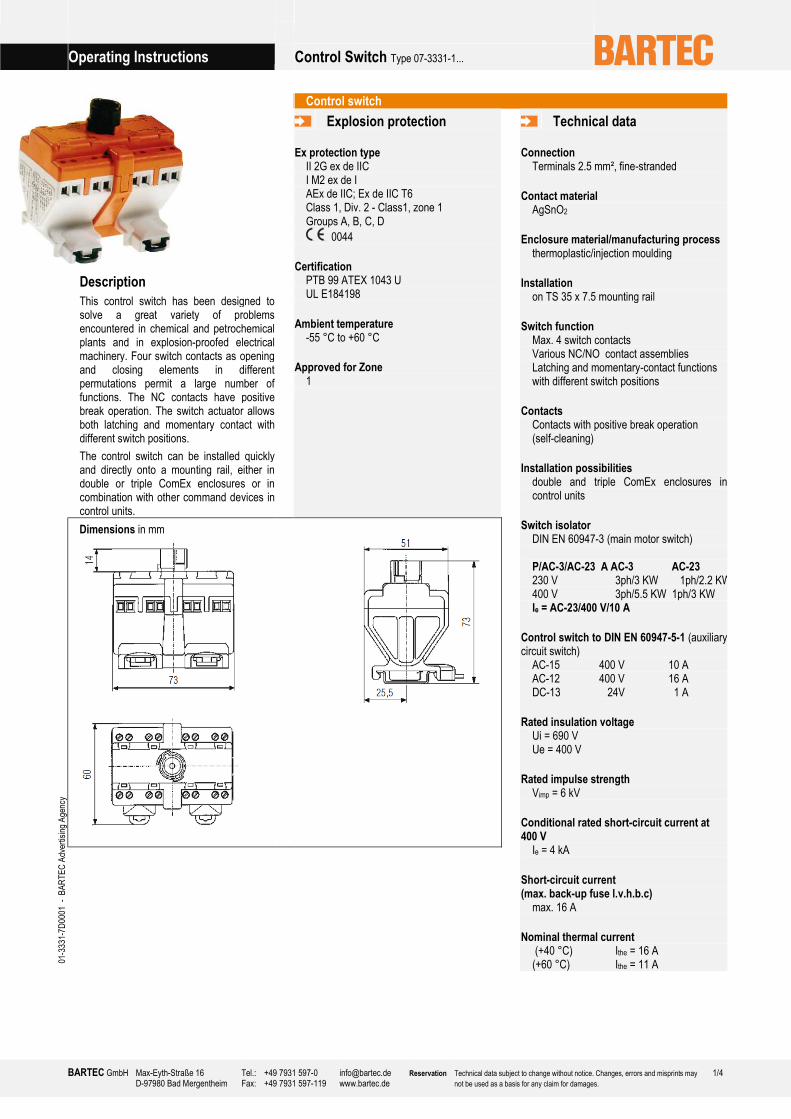
Description
This control switch has been designed to solve a great variety of problems encountered in chemical and petrochemical plants and in explosion-proofed electrical machinery. Four switch contacts as opening and closing elements in different permutations permit a large number of functions. The NC contacts have positive break operation. The switch actuator allows both latching and momentary contact with different switch positions.
The control switch can be installed quickly and directly onto a mounting rail, either in double or triple ComEx enclosures or in combination with other command devices in control units.
Ex protection type II 2G ex de IIC I M2 ex de I AEx de IIC; Ex de IIC T6 Class 1, Div. 2 - Class1, zone 1 Groups A, B, C, D
0044
Certification PTB 99 ATEX 1043 U UL E184198
Ambient temperature -55 °C to +60 °C
Approved for Zone 1
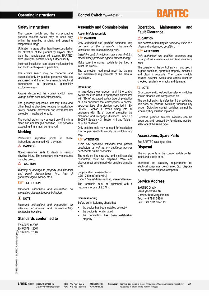
Dimensions in mm
01-333
1-7D
0001
- B
ARTEC Advertising Age
ncy
Connection Terminals 2.5 mm², fine-stranded
Contact material AgSnO2
Enclosure material/manufacturing process thermoplastic/injection moulding
Installation on TS 35 x 7.5 mounting rail
Switch function Max. 4 switch contacts Various NC/NO contact assemblies Latching and momentary-contact functions with different switch positions
Contacts Contacts with positive break operation (self-cleaning)
Installation possibilities double and triple ComEx enclosures in control units
Switch isolator DIN EN 60947-3 (main motor switch) P/AC-3/AC-23 A AC-3 AC-23 230 V 3ph/3 KW 1ph/2.2 KW400 V 3ph/5.5 KW 1ph/3 KW Ie = AC-23/400 V/10 A
Control switch to DIN EN 60947-5-1 (auxiliary circuit switch)
AC-15 400 V 10 A AC-12 400 V 16 A DC-13 24V 1 A
Rated insulation voltage Ui = 690 V Ue = 400 V
Rated impulse strength Vimp = 6 kV
Conditional rated short-circuit current at 400 V
Ie = 4 kA
Short-circuit current (max. back-up fuse l.v.h.b.c)
max. 16 A
Nominal thermal current (+40 °C) Ithe = 16 A (+60 °C) Ithe = 11 A
Operating Instructions Control Switch Type 07-3331-1...
BARTEC GmbH Max-Eyth-Straße 16 D-97980 Bad Mergentheim
Tel.: +49 7931 597-0 Fax: +49 7931 597-119
[email protected] www.bartec.de
Reservation Technical data subject to change without notice. Changes, errors and misprints may
not be used as a basis for any claim for damages. 2/4
01-333
1-7D
0001
- B
ARTEC Advertising Age
ncy
Safety Instructions
The control switch and the correspondingposition selector switch may be used only within the specified ambient and operating temperature range.
Utilisation in areas other than those specified or the alteration of the product by anyone other than the manufacturer will exempt BARTEC from liability for defects or any further liability.
Incorrect installation can cause malfunctioning and the loss of explosion protection.
The control switch may be connected andassembled only by qualified personnel who are authorised and trained to assemble electrical components in hazardous (potentially explosive) areas.
Always disconnect the control switch from voltage before assembly/disassembly.
The generally applicable statutory rules and other binding directives relating to workplace safety, accident prevention and environmental protection must be adhered to.
The control switch may be used only if it is in a clean and undamaged condition. Dust deposits exceeding 5 mm must be removed.
Marking
Particularly important points in these instructions are marked with a symbol:
DANGER
Non-observance leads to death or serious physical injury. The necessary safety measures must be taken.
CAUTION
Warning of damage to property and financial and penal disadvantages (e.g. loss of guarantee rights, liability etc.).
ATTENTION
Important instructions and information on preventing disadvantageous behaviour.
NOTE
Important instructions and information on effective, economical and environmentally compatible handling.
Standards conformed to
EN 60079-0:2006 EN 60079-1:2004 EN 60079-7:2007
Assembly and Commissioning
Assembly/disassembly
CAUTION
Only authorised and qualified personnel may do any of the assembly, disassembly, installation and commissioning work.
Install the control switch in such a way that it is mechanically protected against impact energy.
Make sure the control switch to be fitted is intact (no cracks).
The connection lead must meet the thermal and mechanical requirements of the area of application.
Installation
In hazardous areas groups I and II the control switch must be used in appropriate enclosures with “Ex e” increased safety type of protection or in an enclosure that corresponds to another approved type of protection specified in EN 60079-0 Section 1. When fitting into an enclosure with “Ex e” type of protection the clearance and creepage distances under EN 60079-7 Section 4.3, Section 4.4 and Table 1 must be observed.
Only suitable tools may be used for installation. It is not permissible to modify the switch in any way.
ATTENTION
Avoid any capacitive influence from parallelconductors as well as any additional adverse heat effects on the conductor.
The ends on fine-stranded and multi-stranded conductors must be prepared. Wire end sleeves must be crimped with suitable crimping tools.
Supply cable, cross-sections: 0.75 - 2.5 mm2 (one-wire) 0.75 - 1.5 mm2 (fine-stranded, wire end ferrule)
The terminals must be tightened with a maximum torque of 2.5 Nm.
Commissioning
Before commissioning check that:
• the device has been installed correctly
• the device is not damaged
• the connection has been established properly
Operation, Maintenance and Fault Clearance
CAUTION
The control switch may be used only if it is in a clean and undamaged condition.
ATTENTION
Only authorised and qualified personnel may do any of the maintenance and fault clearance work
The operator of the control switch must keep it in good condition, operate it properly, monitor it and clean it regularly. The control switch, position selector switch and cables must be checked regularly for cracks and damage.
NOTE
Dirty control switches/position selector switchescan be cleaned with compressed air.
The control switch is defective if the switching unit does not perform switching functions any longer. Defective control switches cannot be repaired; they must be replaced.
Defective position selector switches can be taken out and replaced by functioning position selectors of the same type.
Accessories, Spare Parts
See BARTEC catalogue also.
Disposal
The components in the control switch contain metal and plastic parts.
Therefore the statutory requirements for electrical scrap must be observed (e.g. disposal by an approved disposal company).
Service Address
BARTEC GmbH Max-Eyth-Straße 16 D-97980 Bad Mergentheim Tel.: +49 7931 597-0 Fax: +49 7931 597-119

Operating Instructions Control Switch Type 07-3331-1...
BARTEC GmbH Max-Eyth-Straße 16 D-97980 Bad Mergentheim
Tel.: +49 7931 597-0 Fax: +49 7931 597-119
[email protected] www.bartec.de
Reservation Technical data subject to change without notice. Changes, errors and misprints may
not be used as a basis for any claim for damages. 3/4
Contact arrangements in control switch
Type 07-3331-1A01 Type 07-3331-1C06
13 23 33 43
14 24 34 44
X X X XI
0
13 23 33 43
14 24 34 44
I0
13 23 33 43
14 24 34 44
X X
X X
I
0
13 23 33 43
14 24 34 44
I0
II
II
Type 07-3331-1A02 Type 07-3331-1C07
13 23 31 41
14 24 32 42
X X
X X
I
0
13 23 31 41
14 24 32 42
I0
13 23 31 41
14 24 32 42
X X
X X0
I
13 23 31 41
14 24 32 42
0I
II
II
0 / I
Type 07-3331-1A03 Type 07-3331-1E08
11 23 33 43
12 24 34 44
X
X X XI
0
11 23 33 43
12 24 34 44
I0
11 23 33 43
12 24 34 44
X
X
X X
0
I
11 23 33 43
12 24 34 44
0I
II
II
0 / I
Type 07-3331-1A04 Type 07-3331-1E09
11 21 31 43
12 22 32 44
X X X
XI
0
11 21 31 43
12 22 32 44
I0
13 23 33 43
14 24 34 44
X X
X X
I
0
13 23 33 43
14 24 34 44
I0
II
II
0 / I
Type 07-3331-1H05 Type 07-3331-1L01
11 23 33 43
12 24 34 44
X
X
X
X
I
0
11 23 33 43
12 24 34 44
I
0
II
III
III
II
13 23 33 43
14 24 34 44
X
X
X
X
I
013 23 33 43
14 24 34 44
I
0
II
IV
III
II
III
IV
Contact arrangements in switch isolator
Type 07-3331-1N01 Type 07-3331-1N02
01-333
1-7D
0001
- B
ARTEC Advertising Age
ncy
1 3 5 13
2 4 6 14
X X X XI
0
1 3 5 13
2 4 6 14
I0
1 3 5 11
2 4 6 12
X X X
X
I
0
1 3 5 11
2 4 6 12
I0

Operating Instructions Control Switch Type 07-3331-1...
BARTEC GmbH Max-Eyth-Straße 16 D-97980 Bad Mergentheim
Tel.: +49 7931 597-0 Fax: +49 7931 597-119
[email protected] www.bartec.de
Reservation Technical data subject to change without notice. Changes, errors and misprints may not be used as a basis for any claim for damages.
4/4