operating instructions - projectorcentral.com · bfor pluggable equipment, the socket-outlet shall...
TRANSCRIPT

EN
GL
ISH
R
Before operating this product, please read the instructions carefully and save this
manual for future use.
LCD Projector
Operating InstructionsModel No. PT-LB60NTE
PT-LB55NTE
TQBJ 0195
Commercial Use


ENGLISH-3
Pre
par
atio
n
WARNING:BFor permanently connected equipment, a readily accessible disconnect
device shall be incorporated in the building installation wiring;BFor pluggable equipment, the socket-outlet shall be installed near the
equipment and shall be easily accessible.
CAUTION:To assure continued compliance, follow the attached installationinstructions, which includes using the provided power cord and shieldedinterface cables when connecting to computer or peripheral device.If you use serial port to connect PC for external control of projector, youmust use optional RS-232C serial interface cable with ferrite core. Anyunauthorized changes or modifications to this equipment will void theuser’s authority to operate.
Information on Disposal for Users of Waste Electrical & ElectronicEquipment (private households)
This symbol on the products and/or accompanying documentsmeans that used electrical and electronic products should not bemixed with general household waste.For proper treatment, recovery and recycling, please take theseproducts to designated collection points, where they will beaccepted on a free of charge basis. Alternatively, in some
countries you may be able to return your products to your local retailer uponthe purchase of an equivalent new product.Disposing of this product correctly will help to save valuable resources andprevent any potential negative effects on human health and the environmentwhich could otherwise arise from inappropriate waste handling. Pleasecontact your local authority for further details of your nearest designatedcollection point.Penalties may be applicable for incorrect disposal of this waste, inaccordance with national legislation.
For business users in the European Union
If you wish to discard electrical and electronic equipment, please contactyour dealer or supplier for further information.
Information on Disposal in other Countries outside the European Union
This symbol is only valid in the European Union.If you wish to discard this product, please contact your local authorities ordealer and ask for the correct method of disposal.

4-ENGLISH
ContentsPreparationIMPORTANT SAFETY NOTICE ...2Precautions with regard to
safety .........................................5Accessories .................................9Before use ..................................10Location and function of each
part...........................................12
Getting startedSetting-up...................................18Projection methods, Projectorposition, Projection distancesConnections...............................21Connecting to computer,Connecting to video equipment (1),Connecting to video equipment (2)Preparation for the remote
control unit..............................24
Basic operationTurning on the power................26Turning off the power................28
Useful functionsSelecting the input signal .........30Correcting the image position
automatically...........................31Turning off the picture and sound
momentarily ............................32Adjusting the volume ................32Enlarging the picture.................33Displaying two screens.............34Displaying the pointer...............35
Adjustments and settingsOn-screen menus ......................36Menu screens, Menu operationguide, Returning a setting to thefactory defaultAdjusting the picture.................40PICTURE MODE, CONTRAST,BRIGHTNESS, COLOR, TINT,SHARPNESS, COLORTEMPERATURE, Projecting sRGB-compatible pictures,
DAYLIGHT VIEW, AI, DETAILEDSETUPAdjusting the position...............44REALTIME KEYSTONE,KEYSTONE, POSITION, DOTCLOCK, CLOCK PHASE, ASPECT,RESIZING, FRAME LOCKChanging the display
language..................................48Option settings ..........................49INPUT GUIDE, STARTUP LOGO,POINTER SELECT, PC2 SELECT,LAMP POWER, LAMP RUNTIME,POWER OFF TIMER, DIRECTPOWER ON, CONTROL PANEL,AUTO SETUP, SIGNAL SEARCH,INSTALLATION, HIGHLAND,RGB/YPBPR, VOLUME, DETAILEDSETUPSetting up the security
function ...................................54INPUT PASSWORD, PASSWORDCHANGE, TEXT DISPLAY, TEXTCHANGEWireless setup ...........................56
Care and maintenanceWhen the TEMP indicator and the
LAMP indicator are illuminated...............................57
Cleaning and replacing the air filter ..............................59
Replacing the lamp unit ............60Before calling for service..........63Cleaning and maintenance .......64
OthersSpecifications ............................65Appendix ....................................67Projection dimensions calculationmethods, List of compatible signals,Guide screen for computerconnection, Using the SERIALconnectorDimensions ................................72Trademark
acknowledgements ................72

ENGLISH-5
Pre
par
atio
n
Precautions with regard to safetyWARNINGIf you notice smoke, strange smells or noise coming from theprojector, disconnect the mains plug from the mains socket.BDo not continue to use the projector in such cases, otherwise fire or
electric shocks could result.BCheck that no more smoke is coming out, and then contact an Authorised
Service Centre for repairs.BDo not attempt to repair the projector yourself, as this can be dangerous.
Do not install this projector in a place which is not strong enough totake the full weight of the projector.B If the installation location is not strong enough, it may fall down or tip over,
and severe injury or damage could result.
Installation work (such as ceiling suspension) should only be carriedout by a qualified technician.B If installation is not carried out correctly, there is the danger that injury or
electric shocks may occur.
If foreign objects or water get inside the projector, or if the projector isdropped or the cabinet is broken, disconnect the mains plug from themains socket.BContinued use of the projector in this condition may result in fire or electric
shocks.BContact an Authorised Service Centre for repairs.
Do not overload the mains socket.B If the power supply is overloaded (for example, by using too many
adapters), overheating may occur and fire may result.
Do not remove the cover or modify it in any way.BHigh voltages can cause fire or electric shocks.BFor any inspection, adjustment and repair work, please contact an
Authorised Service Centre.
Clean the mains plug regularly to prevent it from becoming covered indust.B If dust builds up on the mains plug, the resulting humidity can damage the
insulation, which could result in fire. Pull the mains plug out from themains socket and wipe it with a dry cloth.
B If not using the projector for an extended period of time, pull the mainsplug out from the mains socket.
Do not do anything that might damage the mains lead or the mainsplug.BDo not damage the mains lead, make any modifications to it, place it near
any hot objects, bend it excessively, twist it, pull it, place heavy objects ontop of it or wrap it into a bundle.

6-ENGLISH
B If the mains lead is used while damaged, electric shocks, short-circuits orfire may result.
BAsk an Authorised Service Centre to carry out any repairs to the mainslead that might be necessary.
Do not handle the mains plug with wet hands.BFailure to observe this may result in electric shocks.
Insert the mains plug securely into the mains socket.B If the plug is not inserted correctly, electric shocks or overheating could
result.BDo not use plugs which are damaged or mains sockets which are coming
loose from the wall.
Do not place the projector on top of surfaces which are unstable.B If the projector is placed on top of a surface which is sloped or unstable, it
may fall down or tip over, and injury or damage could result.
Do not place the projector into water or let it become wet.BFailure to observe this may result in fire or electric shocks.
Do not place the projector on soft materials such as carpets or spongemats.BDoing so may cause the projector to overheat, which can cause burns, fire
or damage to the projector.
Do not place liquid containers on top of the projector.B If water spills onto the projector or gets inside it, fire or electric shocks
could result.B If any water gets inside the projector, contact an Authorised Service
Centre.
Do not insert any foreign objects into the projector.BDo not insert any metal objects or flammable objects into the projector or
drop them onto the projector, as doing so can result in fire or electricshocks.
Keep the batteries out of the reach of infants.B If the batteries are swallowed, death by suffocation may result. If you
believe that the batteries may have been swallowed, seek medical adviceimmediately.
Do not allow the + and - terminals of the batteries to come into contactwith metallic objects such as necklaces or hairpins.BFailure to observe this may cause the batteries to leak, overheat, explode
or catch fire.BStore the batteries in a plastic bag and keep them away from metallic
objects.
During a thunderstorm, do not touch the projector or the cable.BElectric shocks can result.
Do not use the projector in a bath or shower.BFire or electric shocks can result.

ENGLISH-7
Pre
par
atio
n
Do not look into the lens while the projector is being used.BStrong light is emitted from the projector’s lens. If you look directly into this
light, it can hurt and damage your eyes.BBe especially careful not to let young children look into the lens. In
addition, disconnect the mains plug when you are away from theprojector.
Do not place your skin into the light beam while the projector is beingused.BStrong light is emitted from the projector’s lens. If you place directly into
this light, it can hurt or damage your skin.
Do not place your hands or other objects close to the air outlet port.BHeated air comes out of the air outlet port. Do not place your hands or
face, or objects which cannot withstand heat close to this port [allow atleast 15 cm (6˝ ) of space], otherwise burns or damage could result.
Replacement of the lamp should only be carried out by a qualifiedtechnician.BThe lamp has high internal pressure. If improperly handled, explosion
might result.BThe lamp can easily become damaged if struck against hard objects or
dropped, and injury or malfunctions may result.
When replacing the lamp, allow it to cool for at least one hour beforehandling it.BThe lamp cover gets very hot, and touching it can cause burns.
Before replacing the lamp, be sure to disconnect the mains plug fromthe mains socket.BElectric shocks or explosions can result if this is not done.
CautionDo not cover the air inlet port or the air outlet port.BDoing so may cause the projector to overheat, which can cause fire or
damage to the projector.BDo not place the projector in narrow, badly ventilated places such as
closets or bookshelves.BDo not place the projector on cloth or papers, as these materials could be
drawn into the air inlet port.
Do not set up the projector in humid or dusty places or in places wherethe projector may come into contact with smoke or steam.BUsing the projector under such conditions may result in fire or electric
shocks.
When disconnecting the mains lead, hold the plug, not the lead.B If the mains lead itself is pulled, the lead will become damaged, and fire,
short-circuits or serious electric shocks may result.

8-ENGLISH
Always disconnect all cables before moving the projector.BMoving the projector with cables still attached can damage the cables,
which could cause fire or electric shocks to occur.
Do not place any heavy objects on top of the projector.BFailure to observe this may cause the projector to become unbalanced
and fall, which could result in damage or injury.
Do not short-circuit, heat or disassemble the batteries or place theminto water or fire.BFailure to observe this may cause the batteries to overheat, leak, explode
or catch fire, and burns or other injury may result.
When inserting the batteries, make sure the polarities (+ and -) arecorrect.B If the batteries are inserted incorrectly, they may explode or leak, and fire, injury
or contamination of the battery compartment and surrounding area may result.
Use only the specified batteries.B If incorrect batteries are used, they may explode or leak, and fire, injury or
contamination of the battery compartment and surrounding area may result.
Do not mix old and new batteries.B If the batteries are inserted incorrectly, they may explode or leak, and fire,
injury or contamination of the battery compartment and surrounding areamay result.
Do not put your weight on this projector.BYou could fall or the projector could break, and injury may result.BBe especially careful not to let young children stand or sit on the projector.
If not using the projector for an extended period of time, disconnect themains plug from the mains socket.B If dust builds up on the mains plug, the resulting humidity may damage
the insulation, which could result in fire.BThis projector continues to draw approximately 3 W of power even when
the power is turned off.
Disconnect the mains plug from the mains socket as a safetyprecaution before carrying out any cleaning.BElectric shocks can result if this is not done.
If the lamp has broken, ventilate the room immediately. Do not touch orbring your face close to the broken pieces.BFailure to observe this may cause the user to absorb the gas which was
released when the lamp broke and which contains nearly the sameamount of mercury as fluorescent lamps, and the broken pieces maycause injury.
B If you believe that you have absorbed the gas or that the gas has got intoyour eyes or mouth, seek medical advice immediately.
BAsk your dealer to replace the lamp unit and check the inside of theprojector.

ENGLISH-9
Pre
par
atio
n
Card remote control unit (N2QAYA000001 x1)
Mains lead(K2CM3DR00002 x 1)
Carrying bag(TPEP019 x 1)
AAA batteries forremote control unit (x2)
RGB signal cable [1.8 m (5´10˝),K1HA15DA0002 x1]
AccessoriesCheck that all of the accessories shown below have been included with yourprojector.
CD-ROM (TQBH9008 x1)
Ask an Authorised Service Centre to clean inside the projector at leastonce a year.B If dust is left to build up inside the projector without being cleaned out, it
can result in fire or problems with operation.B It is a good idea to clean the inside of the projector before the season for
humid weather arrives. Ask your nearest Authorised Service Centre toclean the projector when required. Please discuss with the AuthorisedService Centre regarding cleaning costs.
We are constantly making efforts to preserve and maintain a cleanenvironment. Please take non repairable units back to your dealer or arecycling company.

10-ENGLISH
Before useCaution when moving the projectorBe sure to attach the lens cover before moving the projector.The projection lens is extremely susceptible to vibration and shocks. Whenmoving the projector, use the accessory carrying bag. When placing theprojector inside the carrying bag, position it so that the lens is facing upward.Do not place the projector with its adjustable legs extended and do not putanything else in the bag other than the projector, cables and the remotecontrol unit.
Cautions regarding setupAvoid setting up in places which are subject to vibration or shocks.The internal parts can be damaged, which may cause malfunctions oraccidents.
Avoid setting up in places which are subject to sudden temperaturechanges, such as near an air conditioner.The life of the lamp may be shortened.
Do not set up the projector near high-voltage power lines or nearmotors.The projector may be subject to electromagnetic interference.
If installing the projector to the ceiling, ask a qualified technician tocarry out all installation work.You will need to purchase the separate installation kit (Model No.ET-PKB30).Furthermore, all installation work should only be carried out by a qualifiedtechnician.
If using this projector at high elevations (above 1 400 m), set the“HIGHLAND” to “ON”. (Refer to page 52.)Failure to observe this may result in malfunctions.

ENGLISH-11
Pre
par
atio
nNotes on useIn order to get the best picture qualityDraw curtains or blinds over any windows and turn off any lights near thescreen to prevent outside light or light from indoor lamps from shining ontothe screen.
Do not touch the surfaces of the lens with your bare hands.If the surface of the lens becomes dirty from fingerprints or anything else, thiswill be magnified and projected onto the screen. Moreover, when not usingthe projector, retract the lens and then cover it with the lens cover.
ScreenDo not apply any volatile substances which may cause discolouration to thescreen, and do not let it become dirty or damaged.
LampThe lamp may need to be replaced earlier due to variables such as individuallamp characteristics, usage conditions and the installation environment,especially when the projector is subjected to continuous use for more than10 hours or the power is frequently turned on and off.
Liquid crystal panelThe liquid crystal panel of the projector is built with very high precisiontechnology to provide fine picture details. Occasionally, a few non-activepixels may appear on the screen as fixed points of blue, green or red.Please note that this does not affect the performance of your LCD.

12-ENGLISH
Location and function of each part
#Projector control panel (page 14)
$Zoom ring (page 27)
%Focus ring (page 27)
&Security lock This can be used to connect a commercially-available theft-preventioncable (manufactured by Kensington). This security lock is compatible withthe Microsaver Security System from Kensington.
'Leg adjuster buttons (L/R) (page 27)These buttons are used to unlock the front adjustable legs. Press to adjustthe angle of tilt of the projector.
(Lens cover)Projection lens*Remote control signal receptor (page 24)
Projector <Top, right and front># $ %
&
'
(
'
*
)

ENGLISH-13
Pre
par
atio
n
#Connector panel (page 16)
$Air outlet portDo not cover this port.
%Speaker&Front adjustable legs (L/R) (page 27)
'Air inlet port, Air filter (page 59)Do not cover this port.
(Lamp unit cover (page 60)
WARNINGDo not place your hands or other objects close to the air outlet port.BHeated air comes out of the air outlet port. Do not place your hands or
face, or objects which cannot withstand heat close to this port [allow atleast 15 cm (6˝ ) of space], otherwise burns or damage could result.
NOTE:BDuring projection of an image, the cooling fan will operate, emitting a
small noise as it operates. This noise may change depending on theambient temperature. Turning the lamp on or off will cause this noise toincrease a little.
BBy using the “OPTION” menu to set “LAMP POWER” to “ECO-MODE”,the operating sound of the fan can be reduced. (Refer to page 50.)
Projector <Back and bottom>
#
(
$ %
'
&

14-ENGLISH
Remote control unit
'
)
.
/
0
2
*
1 5
4
3
+・,-
(
Projector control panel
#PC INPUT indicatorThis indicator illuminates when a signal is being input to the connector (PC1 IN or PC 2 IN) selected using the input select buttons.
# $ % )('&
Menuoperation<on connectorpanel:page 16>
*
+,

ENGLISH-15
Pre
par
atio
n
$LAMP indicator (page 58)This indicator illuminates when it is time to replace the lamp unit. It flashesif a circuit abnormality is detected.
%TEMP indicator (page 57)This indicator illuminates if an abnormally high temperature is detected insidethe projector or around it. If the temperature rises above a certain level, thepower supply will be turned off automatically and the indicator will flash.
& Illumination sensor (page 42)This sensor detects the luminance when the “DAYLIGHT VIEW” functionis operating. Do not cover the projector and do not place any object on theprojector when using it.
'POWER button (pages 26, 28 and 29)This button is used to turn the power on and off. This button on theprojector illuminates red when the projector is in standby mode, and itilluminates green when a picture starts to be projected.
( INPUT SELECT button (pages 27 and 30)This button is used to switch the input signals from the connectedequipment.
)AUTO SETUP button (pages 27 and 31)If this button is pressed while a RGB signal is being projected, the positionof the image and the settings for “DOT CLOCK” and “CLOCK PHASE” willbe adjusted automatically.
*MENU button (pages 36 and 38)This button is used to display the menu screen. When a menu screen isbeing displayed, this button can be used to return to a previous screen orto clear the screen.
+Arrow (FFGGII and HH) buttons (page 38)These buttons are used to select and adjust items in the on-screen menus.
,ENTER button (page 38)This button is used to accept and to activate items selected in the on-screenmenus.
-POINTER button (page 35)This button is used to display a pointer on the projected images.
.PAGE buttonsThese buttons are used when the projector is controlled by means of awireless network. Refer to the accessory CD-ROM for details.
/ INDEX WINDOW button (page 34)This button can be used to split the image projection area into a still pictureand a moving picture. You can also select this function from the on-screenmenu (refer to page 53).
0MULTI-LIVE SELECT buttonThis button is used when the projector is controlled by means of a wirelessnetwork. Refer to the accessory CD-ROM for details.
(continued on next page)

16-ENGLISH
(continued from previous page)
Connector panel
#SERIAL connector (pages 21, 22, 23 and 70)This connector is used to connect a personal computer to the projector inorder to control the projector externally. (RS-232C compatible)
$PC 1 IN connector (pages 21 and 22)This connector is used to input RGB signals and YPBPR signals.
1DIRECT INPUT SELECT buttons (pages 27 and 30)You can select the input signal directly by pushing these buttons.
2SHUTTER button (page 32)This button is used to momentarily turn off the picture and sound. You canalso select this function from the on-screen menu (refer to page 53).
3DEFAULT button (page 39)This button is used to reset the projector adjustment values to the factorydefault settings.
4VOLUME +/- buttons (page 32)These buttons are used to adjust the volume of the sound that is outputfrom the projector’s built-in speaker and VARIABLE AUDIO OUTconnector. Refer to page 52 for details on how to adjust the volumewithout using the remote control unit.
5DIGITAL ZOOM +/- buttons (page 33)These buttons are used to enlarge the projected image.
# $ % & ' (
), *+

ENGLISH-17
Pre
par
atio
n
%PC 2 IN/PC 1 OUT connector (pages 21, 22 and 50)This connector is used to input or output RGB signals and YPBPR signals.Adjust “PC2 SELECT” in the “OPTION” menu to select whether you wantinput or output with this connector.
&S-VIDEO IN connector (pages 23 and 46)This connector is used to input signals from S-VIDEO-compatibleequipment such as a DVD player. The connector is S1 signal compatible,and it automatically switches between 16:9 and 4:3 aspect ratios inaccordance with the type of signal being input.
'AUDIO IN L-R connectors (for S-VIDEO/VIDEO) (page 23)
(Menu operation (page 14)
)VIDEO IN connector (page 23)This connector is used to input video signals from video equipment suchas a video deck.
*VARIABLE AUDIO OUT connector (pages 21, 22, and 23)This connector is used to output the audio signals which are input to theprojector. If audio equipment is connected to this connector, no sound willbe output from the built-in speakers.
+PC 1/2 AUDIO IN connectors (pages 21 and 22)These connectors are used to input audio signals, and they correspond tothe PC 1 IN/PC 2 IN connectors respectively.
,Power input socket (AC IN) (page 26)The accessory mains lead is connected here.Do not use any mains lead other than the accessory mains lead.

18-ENGLISH
Setting-upProjection methodsIn way of installing projector, any one of the following four projection methodsare used. Select whichever projection method matches the setting-upmethod. (The projection method can be set from the “OPTION” menu. Referto page 52 for details.)
BFront-desk projection BFront-ceiling projection
BRear-desk projection(Using a translucent screen)
BRear-ceiling projection(Using a translucent screen)
Menu item Setting
FRONT/DESKINSTALLATION
Menu item Setting
FRONT/CEILINGINSTALLATION
Menu item Setting
REAR/DESKINSTALLATION
Menu item Setting
REAR/CEILINGINSTALLATION
NOTE:BYou will need to purchase the separate ceiling bracket (ET-PKB30)
when using the ceiling installation method.BDo not set up the projector vertically or tilted horizontally, otherwise it
may cause damage to the projector.BDo not set up the projector in a place that is tilted at more than ±30°
vertically. Setting up the projector in places that are tilted at more than±30° vertically may shorten component life.

ENGLISH-19
Get
tin
gst
arte
d
H1
L
SH
L
SW
Projector position
L: Projection distanceSH: Image heightSW:Image widthH1: Distance from centre
of lens to bottom edgeof projected image
Top edge of screen
Screen
Bottom edge of screen
Screen
96.2
mm
(3-2
5/32
˝)

20-ENGLISH
Projection distancesPT-LB60NTE
PT-LB55NTE
Wide (LW) Telephoto (LT)Projection distance (L) Height position
(H1)4:3 Screen size
(diagonal)—0.84 m(33˝)
1.02 m(40˝)1.27 m(50˝)1.52 m(60˝)1.78 m(70˝)2.03 m(80˝)2.29 m(90˝)2.54 m(100˝)3.05 m(120˝)3.81 m(150˝)5.08 m(200˝)6.35 m(250˝)7.62 m(300˝)
1.4 m(4´7˝)1.7 m(5´6˝)2.0 m(6´6˝)2.4 m(7´10˝)2.7 m(8´10˝)3.0 m(9´10˝)3.4 m(11´1˝)4.1 m(13´5˝)5.1 m(16´8˝)6.8 m(22´3)8.4 m(27´6˝)
10.1 m(33´1˝)
1.2 m(3´11˝)1.5 m(4´11˝)1.9 m(6´2˝)2.3 m(7´6˝)2.7 m(8´10˝)3.1 m(10´2˝)3.5 m(11´5˝)4.0 m(13´1˝)4.8 m(15´8˝)6.0 m(19´8˝)8.0 m(26´2˝)
10.0 m(32´9˝)12.0 m(39´4˝)
0.05 m(1-15/16˝)0.06 m(2-11/32˝)0.07 m(2-3/4˝)0.09 m(3-17/32˝)0.10 m(3-29/32˝)0.12 m(4-23/32˝)0.13 m(5-3/32˝)0.15 m(5-7/8˝)0.18 m(7-1/16˝)0.22 m(8-21/32˝)0.30 m(11-25/32˝)0.37 m(14-9/16˝)0.44 m(17-5/16˝)
NOTE:BThe dimensions in the table above are approximate.BFor details about projected image distances, refer to page 67.
Wide (LW) Telephoto (LT)Projection distance (L) Height position
(H1)4:3 Screen size
(diagonal)—0.84 m(33˝)
1.02 m(40˝)1.27 m(50˝)1.52 m(60˝)1.78 m(70˝)2.03 m(80˝)2.29 m(90˝)2.54 m(100˝)3.05 m(120˝)3.81 m(150˝)5.08 m(200˝)6.35 m(250˝)7.62 m(300˝)
1.2 m(3´11˝)1.5 m(4´11˝)1.8 m(5´10˝)2.1 m(6´10˝)2.4 m(7´10˝)2.7 m(8´10˝)3.0 m(9´10˝)3.6 m(11´9˝)4.6 m(15´1˝)6.1 m(20´)7.6 m(24´11˝)9.1 m(29´10˝)
1.1 m(3´7˝)1.4 m(4´7˝)1.7 m(5´6˝)2.1 m(6´10˝)2.5 m(8´2˝)2.8 m(9´2˝)3.2 m(10´5˝)3.5 m(11´5˝)4.3 m(14´1˝)5.4 m(17´8˝)7.2 m(23´7˝)9.0 m(29´6˝)
10.8 m(35´5˝)
0.07 m(2-3/4˝)0.08 m(3-1/8˝)0.11 m(4-5/16˝)0.13 m(5-3/32˝)0.15 m(5-7/8˝)0.17 m(6-11/16˝)0.19 m(7-15/32˝)0.21 m(8-1/4˝)0.25 m(9-13/16˝)0.32 m(12-19/32˝)0.42 m(16-17/32˝)0.53 m(20-27/32˝)0.63 m(24-25/32˝)

ENGLISH-21
Get
tin
gst
arte
d
ConnectionsNotes on connectionsBRead the instruction manual for each peripheral device carefully before
connecting it.BTurn off the power supply for all peripheral devices before making any
connections.B If the cables necessary for connection are not included with the peripheral
device or available as an option, you may need to prepare a proper cablefor the device concerned.
B If there is a lot of jitter in the video signal, the projected image may flicker.In such cases, it will be necessary to connect a TBC (time base corrector).
BRefer to the list on page 68 for details on compatible signals which can beinput to the projector.
BOnly one audio system circuit is available for the AUDIO IN L-Rconnectors, so if you change the audio input source, you will need toremove and insert the appropriate plugs.
Connecting to computer
RGB signal cable(accessory)
RGB signal cable(accessory)
Audio system
Computer
Computer
DIN 8-pin(male)
Computer forcontrol use
Monitor
Refer to the accessory CD-ROM for details on the wireless networkthat can be used for controlling the projector with a personalcomputer.
Serial adapter(ET-ADSER : soldseparately)
22-ENGLISH
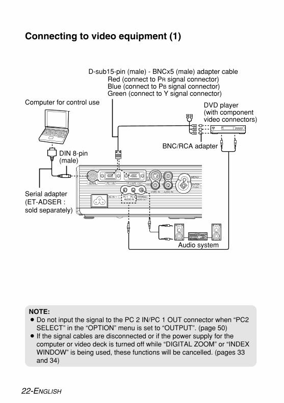
NOTE:BDo not input the signal to the PC 2 IN/PC 1 OUT connector when “PC2
SELECT” in the “OPTION” menu is set to “OUTPUT”. (page 50)B If the signal cables are disconnected or if the power supply for the
computer or video deck is turned off while “DIGITAL ZOOM” or “INDEXWINDOW” is being used, these functions will be cancelled. (pages 33and 34)
Connecting to video equipment (1)
D-sub15-pin (male) - BNCx5 (male) adapter cable
DVD player(with componentvideo connectors)
DIN 8-pin(male)
Computer for control use
Red (connect to PR signal connector)Blue (connect to PB signal connector)Green (connect to Y signal connector)
BNC/RCA adapter
Serial adapter(ET-ADSER :sold separately)
Audio system

ENGLISH-23
Get
tin
gst
arte
d
Connecting to video equipment (2)
DIN 8-pin(male)
DVD player
Video deck
Computer for control use
Serial adapter(ET-ADSER :sold separately)
Audio system

#While pressing the tab, lift the battery cover to remove it.
$ Insert the batteries into the battery holder so that the polarities are correct.
%Replace the battery cover(a click will be heard).
24-ENGLISH
Preparation for the remote control unit
NOTE:BDo not drop the remote control unit.BKeep the remote control unit away from liquids.BRemove the batteries if not using the remote control unit for long periods.BDo not use rechargeable batteries.B If the remote control unit is held so that it is facing directly in front of the
remote control signal receptor, the operating range is withinapproximately 7 m (23´) from the surfaces of the receptor. Furthermore,the remote control unit can be operated from an angle of ±30° to the leftor right and ±15° above or below the receptor.
B If the buttons on the remote control unit are kept pressed, the batterypower will be consumed rapidly.
B If there are any obstacles in between the remote control unit and thereceptor, the remote control unit may not operate correctly.
B If strong light is allowed to shine onto the remote control signal receptor,correct projector operation may not be possible. Place the projector asfar away from light sources as possible.
B If facing the remote control unit toward the screen to operate the projector,the operating range of the remote control unit will be limited by the amountof light reflection loss caused by the characteristics of the screen used.
AAA batteries (two)

ENGLISH-25
Get
tin
gst
arte
d

26-ENGLISH
Turning on the power
Connect the accessory mains lead to the AC INsocket.BInsert the connector into the AC IN socket so that the shape of the
connector matches the shape of the socket. Then insert the mainsplug into the mains socket.
BThe POWER button on the projector will illuminate red.
Press the POWER button.BThe POWER button on the projector will flash green. After a short
period, it will illuminate green, and the startup logo will be displayed.If you would like the startup logo not to be displayed, set “STARTUPLOGO” to “OFF”. (Refer to page 49.)
Turn on the power of all connected devices.BStart the play function of a device such as a DVD player.
NOTE:BA tinkling sound may be heard when the lamp unit is turned on, but this
is not a sign of a malfunction.
#
$
%
)
*
$
&
&
(
'
'
(
&
#
$
AC IN socket Connector
Before turning on the power1. Ensure that all peripheral
devices are connectedproperly.
2. Remove the lens cover.

ENGLISH-27
Bas
ico
per
atio
n
Select the input signal by pressing the INPUTSELECT button or the DIRECT INPUT SELECTbuttons.BA picture will be projected in accordance with the selected input
signal. (page 30)BWhen “SIGNAL SEARCH” is set to “ON”, the projector detects
which signals are being input, and uses these signals forprojection.
BIf no signal is detected, the guide screen for computer connectionwill be displayed (when “INPUT GUIDE” in the “OPTION” menu isset to “DETAILED”. Refer to page 69 for details).
BPress the INPUT SELECT button to finish the input signal search.
Follow the procedure below when you set the projector up first, and whenyou change the placement after original setup.
Press the AUTO SETUP button (when RGBsignals are being input).BSettings such as the position of the
image will be corrected automatically.(page 31)
Adjusting the sizeBTurn the zoom ring to adjust the size of the projected image.
Adjusting the focusBTurn the focus ring to adjust the focus of the projected image.
&
'
)
*
(
Adjusting the angleBPlace the projector so that it is
vertical to the screen.
BWhile pressing the adjuster buttons,adjust the forward/back angle of tilt of theprojector. Adjust so that the projectedimage is placed at the centre of thescreen.
Direct power on functionIf “DIRECT POWER ON” in the “OPTION” menu is set to “ON”, projectionwill start after the mains lead is connected. Refer to page 51 for details.

#・$
#・$
%
28-ENGLISH
NOTE:BYou can also turn off the power by holding down the POWER button for
more than 0.5 seconds.
NOTE:BPress any button other than the POWER button to cancel the “POWER
OFF” screen.BThe “POWER OFF” screen will disappear in 10 seconds.
Turning off the power
Press the POWER button.BThe “POWER OFF” confirmation
screen will be displayed.
Press the POWER buttonagain.BThe lamp unit will switch off and the
picture will stop being projected.(The POWER button on the projector will illuminate orange while thecooling fan is still operating.)
#
$
%Disconnect the mains lead after the POWERbutton on the projector illuminates red.BDisconnect the mains plug from the mains socket first, and then
disconnect the connector from the AC IN socket.
AC IN socket Connector

ENGLISH-29
POWER button on the projector
POWER button status
Red IlluminatedThe projector is in standby mode and image projectionis possible by pressing the POWER button.
A picture is being projected.The lamp is cooling down after the power has beenturned off or while direct power off function isoperating.The projector is preparing for projection after thepower has been turned on while the POWER buttonon the projector is illuminated orange. (After a shortperiod, a picture will be projected.)
The projector is preparing for projection after thepower has been turned on while the POWER buttonon the projector is illuminated red. (After a shortperiod, a picture will be projected.)
Flashing
Illuminated
Illuminated
Flashing
Green
Orange
Projector status
Direct power off functionYou can disconnect the mains lead during projection or immediately afteruse and move the projector. The cooling fan will operate by the internalpower supply to cool down the lamp.BWhen this function is used, it may take more time for the lamp to turn back
on again compared to when the lamp cools down with the mains leadconnected.
BDo not put the projector in a bag while the POWER button on theprojector is illuminated.
CAUTIONIf not using the projector for an extended period of time, disconnect themains plug from the mains socket.B If dust builds up on the mains plug, the resulting humidity may damage the
insulation, which could result in fire.BThis projector continues to draw approximately 3 W of power even when
the power is turned off.
Bas
ico
per
atio
n

30-ENGLISH
Selecting the input signal (INPUT SELECT/ DIRECT INPUT SELECT)You can select the input signal by pressing the INPUT SELECT button or theDIRECT INPUT SELECT buttons.
Press the INPUT SELECT button.BThe input signal selected will change as shown
below each time the INPUT SELECT button ispressed.
Projector controlpanel
INPUT SELECTbutton
Controlpanel
Remotecontrol
unit
Changing signals
PC1 PC2 S-VIDEO
WIRELESS VIDEO
Press the DIRECT INPUT SELECT buttons.BYou can select the input signal directly.
DIRECT INPUTSELECT buttons
Remotecontrol
unit
Changing signals
The signal that is being input to thePC 1 IN connector will be projected.The signal that is being input to thePC 2 IN connector will be projected.The signal that is being input to the S-VIDEO IN connector will be projected.The signal that is being input to theVIDEO IN connector will be projected.The signal that is set by the wirelessnetwork will be projected. (page 56)
NOTE:B“PC2” cannot be selected when “PC2 SELECT” in the “OPTION” menu is
set to “OUTPUT”.

ENGLISH-31
Use
fulf
un
ctio
ns
Projector controlpanel
Correcting the image positionautomatically (AUTO SETUP)This projector can adjust the position of the image and the settings for “DOTCLOCK” and “CLOCK PHASE” when RGB signals are being input.
Press the AUTO SETUP button while RGBsignals are being projected.
BAutomatic positioningwill be carried out.
NOTE:B“SIGNAL SEARCH” will also be carried out. (When “SIGNAL SEARCH”
is set to “ON”, refer to page 51 for details.)B If the dot clock frequency is 100 MHz or higher, “DOT CLOCK”, and
“CLOCK PHASE” will not be adjusted automatically. Refer to page 45 fordetails.
B If the edges of the projected image are indistinct, or if a dark picture isbeing projected, the automatic setup processing may stop automaticallybefore it is complete. If this happens, project a different picture and thenpress the AUTO SETUP button again.
[
Projectedimage
Screen

32-ENGLISH
Turning off the picture and soundmomentarily (SHUTTER)The “SHUTTER” function can be used to momentarily turn off the picture andsound from the projector when the projector is not being used for shortperiods of time, such as during breaks in meetings or when carrying outpreparation. The projector uses less power in “SHUTTER” mode than it doesin normal projection mode.
Press the SHUTTER button.BThe picture and sound will be turned off.BPress any button on either the projector or
remote control unit to return to normal operatingmode.
NOTE:BYou can also select “SHUTTER” from the on-
screen menu (refer to page 53).
Adjusting the volume (VOLUME)You can adjust the volume of the sound that is output from the projector’sbuilt-in speaker and VARIABLE AUDIO OUT connector.
Press the VOLUME +/- button.BPress the + button to raise the volume.BPress the - button to lower the volume.
NOTE:BYou can also select “VOLUME” from the on-
screen menu (refer to page 52).

ENGLISH-33
Enlarging the picture (DIGITAL ZOOM)You can enlarge the projected image and move the enlarged area.
BThe picture will then be enlarged to 1.5 times thenormal size.
BPress the MENU button to return to the normalscreen.
Press the DIGITAL ZOOM +/- button.
NOTE:BThe enlargement ratio can be changed within the range of 1x to 2x, in
steps of 0.1. When RGB signals are being input, the enlargement ratiocan be changed within the range of 1x to 3x, except when the “FRAMELOCK” is set to “ON” (page 47).
B If the type of signal being input changes while the digital zoom functionis being used, the digital zoom function will be cancelled.
Button functions when using “DIGITAL ZOOM”
+button The enlargement ratio will increase.- button The enlargement ratio will decrease.
FG buttons The displayed position will moveupward or downward.
IH buttons The displayed position will moveto the left or right.
Menu operation(on connector panel)
Use
fulf
un
ctio
ns

34-ENGLISH
Displaying two screens (INDEX WINDOW)This function lets you store a picture which is being projected into memory,so that you can display a still picture and a moving picture on the screen.
BThe current moving picture will be captured in astill window.
BPress the MENU button to return to the previousscreen.
Press the INDEX WINDOW button.
NOTE:BThe aspect ratio of the screen changes and the image is vertically
elongated in comparison to a normal image.BWhen the screen size is changed, the picture’s aspect ratio will also
change. Make sure that you fully understand the notes on “ASPECT” onpage 47 before using the “INDEX WINDOW” function.
BYou can also select “INDEX WINDOW” from the on-screen menu (referto page 53).
Movingpicture
Stillpicture
Movingpicture
Button functions when using “INDEXWINDOW”
Press the F or G button to select a screensize.It can switch to three stages.
Stillpicture
Movingpicture
Stillpicture
Movingpicture
Stillpicture
Movingpicture
Press the II or HH button to switchbetween the still picture screen andmoving picture screen.
Press the ENTER button to capture thepresent moving picture in a still window.
Stillpicture
Stillpicture
Movingpicture
Movingpicture
Menu operation(on connector panel)

ENGLISH-35
BA pointer will be displayed in the middle of theprojected image.
BPress the POINTER button to cancel the pointerdisplay.
Press the POINTER button.
NOTE:BThe pointer cannot be displayed when a menu screen is being
displayed.
Moving the pointer
Press the FGIH buttons to move thepointer.
You can select the pointer in “POINTERSELECT” from 3 types (refer to page 50).
Pointer1 Pointer2 Pointer3
Displaying the pointer (POINTER)You can display the pointer on the projected images.
Use
fulf
un
ctio
ns
<Projector control panel>The pointer will move in 4 directions as shownbelow.
<Remote control unit>The pointer will move in 8 directions as shownbelow.
Menu operation(on connector panel)

36-ENGLISH
On-screen menusMenu screensThe various settings and adjustments for this projector can be carried out byselecting the operations from on-screen menus.The general arrangement of these menus is shown below.
Menu Screen(When a VIDEO signal is beinginput)
POSITION menu (page 44)
BPress the MENU button todisplay the menu screen.Refer to page 38 for details onhow to operate the on-screenmenus.
BThe illustrations of the on-screenmenus in this operating instructionsare for the PT-LB60NTE.
PICTURE menu (page 40)

ENGLISH-37
Adju
stm
ents
and
setti
ngs
2/2
LANGUAGE menu (page 48) SECURITY menu (page 54)
WIRELESS menu (page 56)
OPTION menu (page 49)
G F
G F

38-ENGLISH
#Press the MENU button.
$Press the FF or GG button to select an itemfrom the main menu on the left side.
%Press the ENTER button.
Menu operation guide
The menu screen will be displayed.
The selected item will be displayed inorange.The sub-menu for the selected item willbe displayed on the right side.
You can select an item from the sub-menu.
NOTE:BPress the MENU
button to return tothe previousscreen.
Menu operation(on connector panel)

ENGLISH-39
Adju
stm
ents
and
setti
ngs
&Press the FF or GG button to select anitem, and then press the II or HHbutton to adjust the value or changethe setting.If adjusting the items in the “PICTURE”and “POSITION” menus, the menuscreen will disappear and only theselected item will be displayed.
The value and setting indicator will turngreen when any adjustment changesfrom the factory set value. For itemswithout any selective setting or barscale, press the ENTER button. Thenext screen for the item will then bedisplayed.
Unavailable on-screen menu itemsThis projector hasunadjustable items andunusable functionsdepending on the signalbeing input.If an item cannot be adjustedor a function cannot be used,you cannot select thecorresponding item.
Returning a setting to the factory defaultIf you press the DEFAULT button on the remote control unit, you can returnsettings to the factory default settings. However, the operation of this functionvaries depending on which screen is being displayed.
BBWhen a menu screen is being displayedAll the items on the sub-menu which is being displayed will be returned totheir factory default settings, and the value and setting indicator willappear white.
BBWhen an individual adjustment screen is being displayedOnly the item displayed will be returned to the factory default setting, andthe value and setting indicator will appear white.
NOTE:BA triangle symbol below a bar scale
indicates the factory default setting.Items which do not have this trianglesymbol cannot be returned to the factorydefault setting. The positions of thetriangle symbols vary depending on thetype of signal being input.
Indicates the currentadjustment value
Indicates the standardfactory default setting

40-ENGLISH
Adjusting the picture#Press the MENU button to display the menu screen.$Select the “PICTURE” menu from the main menu, and then press the
ENTER button.%Press the F or G button to select an item.&Press the I or H button to adjust the value or change the setting. For
items with selective setting or a bar scale, the individual adjustmentscreen will be displayed. For “DETAILED SETUP”, press the ENTERbutton to display the next screen.
When an S-VIDEO/VIDEO signal isbeing input
When WIRELESS is selected
When an RGB signal is being input
When an YPBPR signal is beinginput
PICTURE MODEWhen an S-VIDEO/VIDEO/YPBPR
signal is being input
When an RGB signal is being inputor WIRELESS is selected
Select the picture mode that bestmatches the image source androom conditions.
ENGLISH-41
Adju
stm
ents
and
setti
ngs
The mode best used in dark roomsis “NATURAL”. For rooms havingregular lighting conditions in use,select “STANDARD”. Forexceptionally bright rooms, use“DYNAMIC”.“BLACKBOARD” is available onlywhen “BLACKBOARD” in the“OPTION” menu is set to “ON”.Select “BLACKBOARD” whenprojecting onto blackboards.
CONTRASTThis adjusts the contrast of thepicture. (Adjust the “BRIGHTNESS”setting first if required beforeadjusting the “CONTRAST” setting.)The picture is bright: I buttonThe picture is dark: H button
BRIGHTNESSThis adjusts the darker areas (blackareas) in the picture.Black areas are too light: I buttonDark areas are too solid: H button
COLOR(S-VIDEO/VIDEO/YPBPR only)The colour is too deep: I buttonThe colour is too pale: H button
TINT(NTSC/NTSC 4.43/YPBPR only)This adjusts the flesh tones in thepicture.The flesh tones are greenish: I buttonThe flesh tones are reddish: H button
SHARPNESSTo soften the picture details: I buttonTo sharpen the picture details: H button
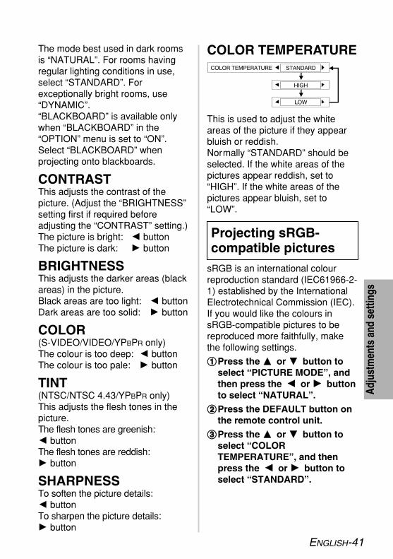
COLOR TEMPERATURE
This is used to adjust the whiteareas of the picture if they appearbluish or reddish.Normally “STANDARD” should beselected. If the white areas of thepictures appear reddish, set to“HIGH”. If the white areas of thepictures appear bluish, set to“LOW”.
sRGB is an international colourreproduction standard (IEC61966-2-1) established by the InternationalElectrotechnical Commission (IEC).If you would like the colours insRGB-compatible pictures to bereproduced more faithfully, makethe following settings.
##Press the FF or GG button toselect “PICTURE MODE”, andthen press the II or HH buttonto select “NATURAL”.
$$Press the DEFAULT button onthe remote control unit.
%%Press the FF or GG button toselect “COLORTEMPERATURE”, and thenpress the II or HH button toselect “STANDARD”.
Projecting sRGB-compatible pictures

42-ENGLISH
DETAILED SETUPYou can adjust the picture quality ofthe projected images in detail. Pressthe ENTER button to display the“DETAILED SETUP” menu.
WHITE BALANCERED/GREEN/BLUE(RGB only)
This is used to adjust the whiteareas of the picture if they appearcolourised. To make the selected colour lighter:I button To make the selected colour stronger:H button
NOTE:B “AI” is disabled when “LAMP
POWER” is set to “ECO-MODE”. (Refer to page 50.)
NOTE:B “AUTO” may not function
correctly if any objects areplaced on the projector.
B “AUTO” will be disabled when“INSTALLATION” in the“OPTION” menu is set to“REAR/DESK” or“REAR/CEILING”.
AI
ONThe lamp is controlled according tothe input signals to project imageswith the best quality.
OFF“AI” is disabled.
DAYLIGHT VIEW
This adjusts the vividness of theprojected images when the projectoris used under bright lighting.
AUTOThe vividness of the projectedimages will be adjusted according tothe lighting condition of the room.
OFF“DAYLIGHT VIEW” is disabled.
NOTE:BsRGB is only enabled when
RGB signals are being input(when “LAMP POWER” is setto “STANDARD”, “AI” is set to“OFF”, and “DAYLIGHT VIEW”is set to “OFF”).

ENGLISH-43
Adju
stm
ents
and
setti
ngs
NOISE REDUCTION(S-VIDEO/VIDEO only)
If the signal is of such poor qualitythat picture interference appears,set “NOISE REDUCTION” to “ON”.To turn off the “NOISEREDUCTION” feature, set to “OFF”.
STILL MODE(S-VIDEO/VIDEO only)
To reduce flickering of still images(vertical flicker), set “STILL MODE”to “ON”.
This should normally be set to“AUTO”. If the signal is of such poorquality that the correct formatcannot be automaticallydistinguished, change the settingmanually to the required TV system.
TV-SYSTEM(S-VIDEO/VIDEO only)
NOTE:BWhen set to “AUTO”, the
projector automaticallydistinguishes betweenNTSC/NTSC 4.43/PAL/PAL60/PAL-M/PAL-N/SECAM signals.
NOTE:BSet to “OFF” when playing
back moving images.

44-ENGLISH
REALTIME KEYSTONE
This projector detects its owndegree of tilt and corrects thekeystone distortion automatically.
ON“REALTIME KEYSTONE” isenabled.
OFF“REALTIME KEYSTONE” isdisabled.
KEYSTONE
This projector detects its owndegree of tilt and corrects thekeystone distortion automatically(“REALTIME KEYSTONE”).However, keystone distortion maystill affect the images in some cases(e.g. when the projector is tiltedslightly and the tilt is correctedslowly by hand or when the screenitself is tilted). In such cases, set“REALTIME KEYSTONE” to “OFF”and correct the vertical keystonedistortion manually.
Adjusting the position#Press the MENU button to display the menu screen.$Select the “POSITION” menu from the main menu, and then press the
ENTER button.%Press the F or G button to select an item. (When RGB signals are
being input, first press the AUTO SETUP button to initiate automaticpositioning. If the optimum setting is not obtained when “AUTOSETUP” is carried out, adjust the items manually.)
&Press the I or H button to adjust the value or change the setting. Foritems with selective setting or a bar scale, the individual adjustmentscreen will be displayed.
When an S-VIDEO/VIDEO signal isbeing input
When an RGB/YPBPR signal isbeing input
When WIRELESS is selected

ENGLISH-45
Adju
stm
ents
and
setti
ngs
POSITION(S-VIDEO/VIDEO/RGB/YPBPR only)
Moves the picture position.Press the ENTER button to display the“POSITION” screen.Press the I or H button to move thepicture horizontally.Press the F or G button to move thepicture vertically.
DOT CLOCK(RGB only)Periodic striped pattern interference(noise) may occur when a stripedpattern such as the one below isprojected. If this happens, press theI or H button to adjust so that anysuch noise is minimised.
CLOCK PHASE(RGB/YPBPR only)Adjust the “DOT CLOCK” settingfirst before carrying out thisadjustment. Press the I or Hbutton to adjust so that the noiselevel is least noticeable.
NOTE:B If signals with a dot clock
frequency of 100 MHz or higherare being input, interferencemay not be completelyeliminated when the “DOT
Picturecondition
Operation
Picturecondition
Operation
Press the F or Hbutton.
Press the G or Ibutton.
NOTE:BVertical keystone distortion can be
corrected to ±30° of the angle of tilt.However, the greater the correctionamount, the more the picture qualitywill deteriorate, and the harder it willbecome to achieve a good level offocus. To obtain the best picturequality, set up the projector andscreen in such a way that theamount of keystone correctionrequired is as minimal as possible.
BThe picture size will also changewhen correction of keystonedistortion is carried out.
BThe ratio of length and width ofan image may become incorrectdepending on the amount of thekeystone correction.
BKeystone distortion of the on-screen display will not be corrected.
BYou can correct the keystonedistortion manually when“REALTIME KEYSTONE” is set to“ON”. However, when you turn onthe power, the amount ofcorrection will be reset and“REALTIME KEYSTONE” willfunction again if the tilt is differentfrom the last time you used theprojector. If you correct thekeystone distortion manually when“REALTIME KEYSTONE” is set to“OFF”, the amount of correction
will be stored by the projectoreven after the power is turned off.

46-ENGLISH
CLOCK” and “CLOCK PHASE”adjustments are carried out.
S4:3The size of the input signal iscompressed to 75% and projected.(This is useful for projecting apicture with a 4:3 aspect ratio onto a16:9 screen.)
AUTO(S-VIDEO only)When an S1 video signal is beinginput, the aspect ratio is changedautomatically to project a 16:9picture.
4:3The input signal is projected withoutchange.
16:9The picture is compressed to a ratioof 16:9 and projected.
S1 video signalsB S1 video signals are a type of
video signal with an aspect ratioof 16:9 which include a detectorsignal. This detector signal isoutput by some sources such aswide-vision video decks.
B When “ASPECT” is set to“AUTO”, the projector recognizesthe detector signal andautomatically switches the aspectratio to 16:9.
When a horizontallysqueezed signal isbeing input.
When a 4:3 signalis being input.
[
[
When using the 16:9 screen
ASPECT(S-VIDEO/VIDEO/480i, 576i, 480pand 576p YPBPR only)

ENGLISH-47
Adju
stm
ents
and
setti
ngs
RESIZING(S-VIDEO/VIDEO/RGB/YPBPR only)
This should normally be set to “ON”.(This setting is only for signalswhich have lower resolutions thanthe LCD panels. Refer to page 68for details.)
ONThe pixel resolution of the inputsignal is converted to the sameresolution as the LCD panels beforebeing projected. This may sometimes causeproblems with the quality of thepicture.
OFFThe input signal is projected at itsoriginal resolution, with no pixelconversion. The projected picturewill be smaller than normal, soadjust the zoom setting or move theprojector forwards or backwards toadjust the picture size if necessary.If set to “OFF”, some features, suchas “DIGITAL ZOOM”, “REALTIMEKEYSTONE”, “KEYSTONE” or“INDEX WINDOW” will not function.
FRAME LOCK(RGB only)
If the picture’s condition is bad whilean RGB moving picture is projected,set “FRAME LOCK” to “ON”. Referto page 68 for compatible RGBsignals.
NOTE:B If using this projector in places
such as cafes or hotels todisplay programmes for acommercial purpose or forpublic presentation, note that ifthe aspect ratio (16:9)selection function is used tochange the aspect ratio of thescreen picture, you may beinfringing the rights of theoriginal copyright owner forthat programme undercopyright protection laws.
B If a 4:3 picture is projectedonto a 16:9 screen, distortionmay occur around the edges ofthe picture so that part of thepicture is no longer visible.Programmes which have 4:3aspect ratios should be viewedin 4:3 mode to give properconsideration to the aims andintentions of the originalprogramme’s creator.

48-ENGLISH
Changing the display language#Press the MENU button to display the menu screen.$Select the “LANGUAGE” menu from the main menu, and then press
the ENTER button.%Press the FF or GG button to select a language, and then press the
ENTER button.
1/2
G
Indicates the language whichis currently set
2/2F
F G

ENGLISH-49
Adju
stm
ents
and
setti
ngs
Option settings#Press the MENU button to display the menu screen.$Select the “OPTION” menu from the main menu, and then press the
ENTER button.%Press the F or G button to select an item.&Press the I or H button to change the setting. For “DETAILED
SETUP”, press the ENTER button to display the next screen.
DETAILEDThe input signal information will bedisplayed in detail.
OFFThe input signal information will notbe displayed.
SIMPLEOnly the name of the input signalwill be displayed.
STARTUP LOGO
ONThe “Panasonic” logo will bedisplayed when the power is turnedon.
OFFThe “Panasonic” logo will not bedisplayed when the power is turnedon.
INPUT GUIDE
When the input signal is changed,the input signal information will bedisplayed in the upper right cornerof the projected images. You canselect the level of the input signalinformation.
F G NOTE:B If “INPUT GUIDE” is set to
“DETAILED”, the guide screenfor computer connection will bedisplayed when PC1 or PC2 isselected and no signal is beinginput to the PC 1 IN or PC 2 INconnector. If you would like theguide screen not to bedisplayed, set “INPUT GUIDE”to “SIMPLE” or “OFF”.

50-ENGLISH
LAMP POWER
This setting changes the lampbrightness. When set to “ECO-MODE”, the luminance of the lampis reduced, but the projector usesless power, and the operating noiseis also reduced. This can help toextend the lamp’s operating life. Ifusing the projector in small roomswhere high luminance is notrequired, it is recommended thatyou set the “LAMP POWER” to“ECO-MODE”.
LAMP RUNTIMEThis setting displays the usage timefor the lamp unit which is currentlybeing used. When replacing thelamp unit, follow the instructions onpage 61, and reset “LAMPRUNTIME” to “0”.
POINTER SELECT
If you press the POINTER button onthe remote control unit, the pointerwill be displayed. You can select thepointer from 3 types as shownbelow (refer to page 35).
「 」A double circle will bedisplayed.
「 」A circle with a cross will bedisplayed.
「 」A hand will be displayed.
PC2 SELECT
This setting is used to select thefunction of the PC 2 IN/PC 1 OUTconnector. When set to “INPUT”, itis set to the PC 2 IN connector.When set to “OUTPUT”, it is set tothe PC 1 OUT connector.
NOTE:B “LAMP POWER” cannot be set
when no signal is being input.
NOTE:BThe lamp’s operating life varies
depending on the usageconditions (such as the “LAMPPOWER” setting and thenumber of times the power isturned on and off).

ENGLISH-51
Adju
stm
ents
and
setti
ngs
AUTO SETUP
This should normally be set to“AUTO”.
AUTO“AUTO SETUP” will be carried outwhen the input signal is changed toRGB.
BUTTON“AUTO SETUP” will function onlywhen you press the AUTO SETUPbutton.
SIGNAL SEARCH
This should normally be set to “ON”.
ONWhen the power is turned on and“AUTO SETUP” is running, theprojector detects which signals arebeing input, and uses these signalsfor projection. (If a picture is being projected, thesignal source is not automaticallychanged.)
OFFUse this setting when you do notwant the signal source to bechanged automatically when thepower is turned on and “AUTOSETUP” is running.
POWER OFF TIMERIf no signal is input to the projectorfor the duration of the period youset, the projector will return tostandby mode. The period can beset from 15 minutes to 60 minutes in5 minute intervals. If you don’t usethis feature, set it to “DISABLE”.
DIRECT POWER ON
This sets the projector’s start upstatus for when the mains lead isconnected.
OFFThe projector will start from thesame status as when the mainslead was disconnected. If the mainslead was disconnected duringprojection when the projector wasused the last time, projection willstart after the mains lead isconnected.
ONThe projection will start after themains lead is connected.
CONTROL PANEL
To disable the buttons on theprojector, set “CONTROL PANEL”to “INVALID”. A confirmation screenwill then be displayed. Select “OK”by using I or H button. To use thebuttons on the projector, set to“VALID” by using the remote controlunit.

52-ENGLISH
RGB/YPBPR(480i, 576i, 480p, 576p, 1 080/60i,1 080/50i, 720/60p and VGA480signals only)
This sets the signal that is input tothe PC 1 IN and PC 2 IN/PC 1 OUTconnector.Normally “AUTO” should beselected. RGB or YPBPR is selectedautomatically depending on thesynchronising signal status.If an image is not projectedcorrectly, select “RGB” or “YPBPR”in accordance with the input signal.
VOLUMEYou can adjust the volume of thesound that is output from theprojector’s built-in speaker andVARIABLE AUDIO OUT connector.
INSTALLATION
This setting should be changed inaccordance with the projectorsetting-up method. (Refer to page18.)
FRONT/DESKWhen the projector is placed on adesk or similar in front of a screen.
FRONT/CEILINGWhen the projector is placed in frontof a screen and suspended from aceiling using a ceiling bracket (soldseparately).
REAR/DESKWhen using a translucent screenand the projector is placed on adesk or similar.
REAR/CEILINGWhen using a translucent screenand the projector is suspended froma ceiling using a ceiling bracket(sold separately).
HIGHLAND
Set “HIGHLAND” to “ON”, whenusing this projector at highelevations (above 1 400 m) only.

ENGLISH-53
image are not visible, select thisitem.
XGA MODE[RGB(XGA) only]
Adjust this item if the projectedimage overflows from the screenwhen an XGA signal is being input.
XGASelect this item normally.
WXGASelect this item when the edges ofthe projected image are not visibleor the projected image is verticallyelongated.
BLACKBOARD
Set to “ON” when “PICTUREMODE” is set to “BLACKBORD”.(Refer to page 40.)
BACK COLOR
This sets the colour which isprojected onto the screen when nosignal is being input to the projector.
DETAILED SETUPPress the ENTER button to displaythe “DETAILED SETUP” menu.
INDEX WINDOWThis functions in the same way asthe “INDEX WINDOW” button onthe remote control unit. Refer topage 34 for details.
SHUTTERThis functions in the same way asthe “SHUTTER” button on theremote control unit. Refer to page32 for details.
OSD DESIGN
You can select the background forthe OSD from 3 types.
TYPE1Transparent black
TYPE2Solid blue
TYPE3Transparent navy blue
SXGA MODE[RGB(SXGA) only]
Adjust this item if the projectedimage overflows from the screenwhen an SXGA signal is beinginput.
SXGASelect this item normally.
SXGA+When the edges of the projected
Adju
stm
ents
and
setti
ngs

54-ENGLISH
Setting up the security functionThis projector is equipped with a security function. A password input screencan be displayed, or a company URL can be set up and displayed at thebottom of the projected image.
#Press the MENU button todisplay the menu screen.
$Select the “SECURITY” menufrom the main menu, and thenpress the ENTER button.
INPUT PASSWORD
PASSWORD CHANGEPasswords can be changed. Pressthe ENTER button to display the“PASSWORD CHANGE” screen.
#Set a password by pressing theF,G,I, and H buttons. (A maximum of 8 buttons can beset.)
$Press the ENTER button.
%Enter the password again forconfirmation.
&Press the ENTER button.
(When you use the “SECURITY”function for the first time)Press the F, H, G, I, F, H, Gand I buttons in order, then pressthe ENTER button.
(When a password change hasbeen made before)Type in the changed password, thenpress the ENTER button.
%Press the F or G button toselect an item.
&Press the I or H button to
change the setting. For “PASSWORD CHANGE”and “TEXT CHANGE”, pressthe ENTER button to displaythe next screen.
The password input screen can bedisplayed when the power is turnedon. All of the controls other than thePOWER button are disabled unlessthe password is entered correctly.
OFF“INPUT PASSWORD” is disabled.
ON“INPUT PASSWORD” is enabled.

ENGLISH-55
TEXT DISPLAY
You can set text to be displayed atthe bottom of the projected image atall times.
OFF“TEXT DISPLAY” is disabled.
ON“TEXT DISPLAY” is enabled.
TEXT CHANGEThe text which is displayed when“TEXT DISPLAY” is set to “ON” canbe changed.Press the ENTER button to displaythe “TEXT CHANGE” screen.
#Press the F, G, I and Hbuttons to select the characters,then press the ENTER button.(You can enter 22 characterscontinuously.)CSelect “DELETE” to delete a
character.
$Press the F, G, I and Hbuttons to select “OK”, then pressthe ENTER button.CSelect “CANCEL” to cancel the
change.
NOTE:BThe entered password will
appear as . It will not bedisplayed on the screen.
B If you enter the wrongpassword, an error messagewill be displayed. Enter thecorrect password again.
Adju
stm
ents
and
setti
ngs

56-ENGLISH
Wireless setupYou need to make adjustments on some items when controlling the projectorwith a personal computer by means of the wireless network. Refer to theaccessory CD-ROM for details.
INPUT PASSWORDSet to “ON” if you want passwordconfirmation to be used whencontrolling the projector with apersonal computer by means of thewireless network.
PASSWORD CHANGEPasswords can be changed.
WEB CONTROLTo control the projector with apersonal computer by means of thewireless network, set the “WEBCONTROL” to “ON”.
STATUSThe wireless settings will bedisplayed.
INITIALIZEWireless settings can be returned tothe factory default settings.
NETWORKSelect the network setting you wantto use.
NAME CHANGEThe name for this projector can beset.

ENGLISH-57
Car
ean
dm
aint
enan
ce
When the TEMP indicator and theLAMP indicator are illuminatedThere are two indicators on the control panel of the projector which giveinformation about the operating condition of the projector. These indicatorsilluminate or flash to warn you about problems that have occurred inside theprojector, so if you notice that one of the indicators is on, turn off the powerand check the table below for the cause of the problem.
Problem
Indicatordisplay
The surrounding temperature orthe temperature inside theprojector has become unusuallyhigh.
Illuminated (red)(Lamp unit on)
BThe ventilation holes may be covered.BThe ambient temperature in the place of use may be too high.BThe air filter may be blocked.
BUncover the ventilation holes.BSet up the projector in a place where the temperature is
between 0 °C (32 °F) and 40 °C (104 °F) and the humidity isbetween 20% and 80% (with no condensation). [If you set the“HIGHLAND” to “ON” (page 52), set up the projector in a placewhere the temperature is between 0 °C (32 °F) and 35 °C(95 °F) and the humidity is between 20% and 80% (with nocondensation).]
BDisconnect the mains lead by following the procedure on page28, and then clean the air filter. (Refer to page 59.)
Possiblecause
Remedy
The surrounding temperature orthe temperature inside theprojector has becomedangerously high, causing thelamp unit to automatically shutoff.
Flashing (red)(Lamp unit off)
TEMP indicator
LAMP indicator
TEMP indicator

58-ENGLISH
Remedy
Problem
Indicatordisplay
Flashing (red)
It is nearly time toreplace the lampunit.
Illuminated (red)
An abnormality has been detected in the lampcircuit.
BDoes “REPLACELAMP” appear onthe screen afterthe projector isturned on?
BThis occurs whenthe operation timefor the lamp unit isnearing 1 800hours (when“LAMP POWER”has been set to“STANDARD” andwhen “AI” hasbeen set to“OFF”). Ask yourdealer or anAuthorisedService Centre toreplace the lampunit. (page 60)
Possiblecause
BThe power mayhave been turnedon straight awayafter it was turnedoff.
BWait for a whileuntil the lamp unitcools down beforeturning the powerback on again.
BThere may be anabnormality in thelamp circuit.
BThe lamp unit maybe blown.
BDisconnect themains lead byfollowing theprocedure onpage 28, and thencontact anAuthorisedService Centre.
BAsk your dealer oran AuthorisedService Centre toreplace the lampunit. (page 60)
LAMP indicator
NOTE:BBe sure to disconnect the mains lead by following the procedure given
in “Turning off the power” on page 28 before carrying out any of theprocedures in the “Remedy” column.
B If the TEMP indicator is illuminated and the power turns off after theprocedures in the “Remedy” column have been carried out, it means anabnormality has occurred. Please contact an Authorised Service Centreso that the necessary repairs can be made.

ENGLISH-59
Car
ean
dm
aint
enan
ce
Cleaning and replacing the air filterIf the air filter becomes clogged with dust, the internal temperature of theprojector will rise, the TEMP indicator will illuminate and the projector’spower will turn off (the TEMP indicator will flash after the power is turned off).The air filter should be cleaned every 100 hours of use.
%Replace the air filter, and theninstall the air filter cover.
CleaningUse a vacuum cleaner to clean offany accumulated dust.
Replacement procedure#Turn off the power and
disconnect the mains lead.Be sure to disconnect the mainslead by following the proceduregiven on page 28.
$Gently turn the projectorupside down, and then removethe air filter cover.
NOTE:B If the dust cannot be cleaned
by a vacuum cleaner, removethe air filter and soak it inwater, and then wash out thedust by hand. Be sure to installthe air filter after it has dried.
BDo not use detergent whenwashing the air filter.
B If the dust cannot be removedby cleaning, it is time toreplace the air filter. Pleaseconsult your dealer.Furthermore, if the lamp unit isbeing replaced, replace the airfilter at this time also.
NOTE:BBe sure to install the air filter
before using the projector. Ifthe projector is used withoutthe air filter installed, dust andother foreign particles will bedrawn into the projector, andmalfunctions will result.
Air filter cover
Air filter
Air filter cover

60-ENGLISH
Replacing the lamp unitWarningWhen replacing the lamp, allow itto cool for at least one hourbefore handling it.BThe lamp cover gets very hot,
and touching it can cause burns.
Notes on replacing the lampunitBThe light generating lamp is
made of glass, so dropping it orallowing it to hit hard objects maycause it to burst. Be careful whenhandling the lamp.
BDispose of the removed old lampwith the same care that would betaken with a fluorescent light.
BA Phillips screwdriver isnecessary for removing the lampunit.
Lamp unit replacementperiodThe lamp is a consumable product.Even when the full life of the bulbhas not been exhausted, thebrightness of the light will graduallydecline. Therefore periodicreplacement of the lamp isnecessary.The intended lamp replacementinterval is 2 000 hours, but it ispossible that the lamp may need tobe replaced earlier due to variablessuch as a particular lamp’scharacteristics, usage conditionsand the installation environment.Early preparation for lampreplacement is encouraged.The lamp will automatically shut offafter approximately 10 minuteswhen 2 000 hours of use have beenreached because of a much greaterchance of it exploding after thistime.
NOTE:BThe projector is not supplied
with a replacement lamp unit.Please ask your dealer fordetails. Lamp unit product no.: ET-LAB30
CAUTION:BDo not use any lamp unit other
than the one with the productnumber indicated above.
NOTE:BThe usage hours explained
above are for when “LAMPPOWER” in the “OPTION”menu has been set to“STANDARD” and when “AI” inthe “PICTURE” menu hasbeen set to “OFF”. If “LAMPPOWER” is set to “ECO-MODE”, or “AI” is set to “ON”,the life of the lamp can beextended.
BWhile 2 000 hours is theintended replacement interval,it is not a period of timecovered by warranty.
ENGLISH-61
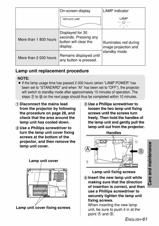
Lamp unit replacement procedure
#Disconnect the mains leadfrom the projector by followingthe procedure on page 28, andcheck that the area around thelamp unit has cooled down.
$Use a Phillips screwdriver toturn the lamp unit cover fixingscrews at the bottom of theprojector, and then remove thelamp unit cover.
%Use a Phillips screwdriver toloosen the two lamp unit fixingscrews until the screws turnfreely. Then hold the handles ofthe lamp unit and gently pull thelamp unit out from the projector.
& Insert the new lamp unit whilemaking sure that the directionof insertion is correct, and thenuse a Phillips screwdriver tosecurely tighten the lamp unitfixing screws.When inserting the new lampunit, be sure to push it in at thepoint A and B.
LAMP indicatorOn-screen display
Illuminates red duringimage projection andstandby mode.
Displayed for 30seconds. Pressing anybutton will clear thedisplay.
More than 1 800 hours
Remains displayed untilany button is pressed.
More than 2 000 hours
NOTE:B If the lamp usage time has passed 2 000 hours (when “LAMP POWER” has
been set to “STANDARD” and when “AI” has been set to “OFF”), the projectorwill switch to standby mode after approximately 10 minutes of operation. Thesteps ) to . on the next page should thus be completed within 10 minutes.
Car
ean
dm
aint
enan
ce
Lamp unit cover
Lamp unit cover fixing screws
BA
Handles
Lamp unit fixing screws

62-ENGLISH
' Install the lamp unit cover, andthen use a Phillips screwdriverto securely tighten the lampunit cover fixing screws.
(Connect the mains lead.)Press the POWER button so
that a picture is projected ontothe screen.
*Press the MENU button todisplay the menu screen, andthen press the F or G buttonto select the “OPTION” menu.
+Press the ENTER button, andthen press the F or G buttonto select “LAMP RUNTIME”.
,Press and hold the ENTERbutton for approximately 3seconds.The “LAMP RUNTIME” screenwill be displayed.
-Press the POWER button to turn off the power.
.Disconnect the mains leadafter the POWER button on theprojector illuminates red.This will reset the cumulativeusage time for the lamp unit to “0”.
NOTE:BBe sure to install the lamp unit
and the lamp unit coversecurely. If they are not securelyinstalled, it may cause theprotection circuit to operate sothat the power cannot be turnedon.
NOTE:BPress any button other than
the POWER button to cancelthe “LAMP RUNTIME” screen.
NOTE:BIf “DIRECT POWER ON” in the
“OPTION” menu has been setto “ON”, projection will startafter the mains lead isconnected. Refer to page 51for details.

ENGLISH-63
Before calling for serviceBefore calling for service, check the following points.
Problem Possible cause PagePower does notturn on.
No pictureappears.
The picture isfuzzy.
The colour ispale or grayish.
No sound canbe heard.
The remotecontrol unitdoes notoperate.
The buttons onthe projector donot function.
BThe mains lead may not be connected.BThe main power supply is not being supplied to the
mains socket.BTEMP indicator is illuminated or flashing. BLAMP indicator is illuminated or flashing. BThe lamp unit cover has not been securely installed.
BThe video signal input source may not beconnected properly.
BThe input selection setting may not be correct. BThe “BRIGHTNESS” adjustment setting may be at
the minimum possible setting.BThe “SHUTTER” function may be in use.
BThe lens cover may still be attached to the lens.BThe lens focus may not have been set correctly. BThe projector may not be at the correct distance
from the screen.BThe lens may be dirty.BThe projector may be tilted too much.
B “COLOR” or “TINT” adjustment may be incorrect. BThe input source which is connected to the
projector may not be adjusted correctly.
BThe audio signal source may not be connectedproperly.
BThe volume adjustment may be at the lowestpossible setting.
BA cable may be connected to the VARIABLEAUDIO OUT connector.
BThe battery may be weak.BThe battery may not be inserted correctly.BThe remote control signal receptor on the projector
may be obstructed.BThe remote control unit may be out of the
operation range.
BThe “CONTROL PANEL” may be set to “INVALID”. In order to set the “CONTROL PANEL” to “VALID”without using the remote control unit, keep holdingdown the ENTER button on the projector and pressthe MENU button for more than 2 seconds.
––
5758–
–
3041
32,53
–2720
–18
41–
–
32,5221,22,23
–2424
24
51
Car
ean
dm
aint
enan
ce

64-ENGLISH
The picture doesnot displaycorrectly.
Picture fromcomputer doesnot appear.
Problem Possible causeBThe signal format (“TV-SYSTEM”) may not be set
correctly.BThere may be a problem with the video tape or
other signal source.BA signal which is not compatible with the projector
may be being input.
BThe cable may be too long.BThe external video output for the laptop computer
may not be set correctly.(The actual method varies depending on the typeof computer, so refer to the documentationprovided with your computer for further details.)
B If an PC INPUT indicator is turned off, the videosignals may not be output from the computer.
B “PC2 SELECT” in the “OPTION” menu is set to“OUTPUT” when the signals are input to PC 2IN/PC 1 OUT connector.
Page43
–
68
–69
14
50
Before carrying out cleaning and maintenance, besure to disconnect the mains plug from the mainssocket.Wipe the cabinet with a soft, dry cloth.If the cabinet is particularly dirty, soak the cloth in water with a small amountof neutral detergent in it, squeeze the cloth very well, and then wipe thecabinet. After cleaning, wipe the cabinet dry with a dry cloth. If using achemically-treated cloth, read the instructions supplied with the cloth beforeuse.Do not wipe the lens with a cloth that is dusty or which produces lint.If any dust or lint gets onto the lens, such dust or lint will be magnified andprojected onto the screen. Use a blower to clean any dust and lint from thelens surface, or use a soft cloth to wipe off any dust or lint.
Cleaning and maintenance

ENGLISH-65
Oth
ers
SpecificationsPower supply: 100 V - 240 V ~, 50 Hz/60 HzPower consumption: 300 W [During standby (when fan is
stopped): Approx. 3 W]Amps: 3.5 A - 1.8 ALCD panel:
Panel size (diagonal):PT-LB60NTE: 0.8 type (20.32 mm)PT-LB55NTE: 0.7 type (17.78 mm)
Aspect ratio: 4:3Micro lens array: AvailableDisplay method: 3 transparent LCD panels (RGB)Drive method: Active matrix methodPixels: 786 432 (1 024 x 768) x 3 panels
Lens: Manual zoom (1.2x) / Manual focusF 1.7 - 1.8 f 24.0 mm - 28.8 mm
Lamp: UHM lamp (220 W)Luminosity:
PT-LB60NTE: 3 200 lmPT-LB55NTE: 2 500 lm
Scanning frequency (for RGB signals):Horizontal scanning frequency: 15 kHz - 91 kHzVertical scanning frequency: 50 Hz - 85 HzDot clock frequency: Less than 100 MHz
YPBPR signals: 480i, 576i, 480p, 576p, 1 080/60i, 1 080/50i, 720/60pColour system: 7 (NTSC/NTSC 4.43/PAL/PAL-M/PAL-N/PAL60/SECAM)Projection size: 838.2 mm - 7 620 mm (33˝ - 300˝)Throw distance:
PT-LB60NTE: 1.1 m - 10.8 m (3´7˝ - 35´5˝)PT-LB55NTE: 1.2 m - 12.0 m (3´11˝ - 39´4˝)
Optical axis shift:PT-LB60NTE: 6:1 (fixed)PT-LB55NTE: 9:1 (fixed)
Screen aspect ratio: 4:3Installation: Front/Desk
Front/CeilingRear/DeskRear/Ceiling (menu selection)
Speaker: 4 cm x 3 cm oval x 1Max. usable volume output: 1 W (mono)Wireless LAN: IEEE802.11 b/gConnectors
PC IN/OUT: Dual line, D-sub HD 15-pin (female)

66-ENGLISH
(One line is available for input and output,selectable using an on-screen menu)
During RGB input/output:R.G.B.: 0.7 V [p-p], 75 ΩG.SYNC: 1.0 V [p-p], 75 ΩHD, VD: TTL, automatic positive/negative polarity compatible
During YPBPR input/output:Y: 1.0 V [p-p] (Including sync), 75 ΩPB, PR : 0.7 V [p-p], 75 Ω
VIDEO IN: Single-line, RCA pin jack, 1.0 V [p-p], 75 ΩS-VIDEO IN: Single-line, Mini DIN 4-pin
Y 1.0 V [p-p], C 0.286 V [p-p], 75 ΩAUDIO IN (for S-VIDEO/VIDEO): Single-line, 0.5 V [rms] RCA pin jack x 2 (L-R)PC AUDIO IN: Dual-line, 0.5 V [rms] M3 jack (Stereo MINI)VARIABLE AUDIO OUT: Single-line, 0.5 V [rms] M3 jack (Stereo MINI)
(Monitor output/stereo compatible)0 V [rms] - 2.0 V [rms] (variable)
SERIAL: DIN 8-pin RS-232C compatibleCabinet: Moulded plastic (PC/ABS)Dimensions:
Width: 327 mm (12-27/32˝)Length: 233 mm (9-5/32˝)(without lens cover)Height: 83 mm (3-1/4˝)
Weight: 2.6 kg (5.7 lbs.)Operating environment:
Temperature: 0 °C - 40 °C (32 °F - 104 °F)[When the “HIGHLAND” is set to “ON”(page 52): 0 °C - 35 °C (32 °F - 95 °F)]
Humidity: 20% - 80% (no condensation)Certifications: EN60950, EN55022, EN61000-3-2,
EN61000-3-3, EN55024<Remote control unit>
Power supply: 3 V DC (AAA battery x 2)Operating range: Approx. 7 m (23´) (when operated directly
in front of signal receptor)Weight: 74 g (2.6 ozs.) (including battery)Dimensions:
Width: 51.5 mm (2˝ ) Length: 123 mm (4-13/16˝ ) Height: 21.1 mm (-13/16˝ )
<Options>Ceiling bracket ET-PKB30Wireless remote control unit ET-RM300Serial adapter ET-ADSER(DIN 8-pin/D-sub 9-pin)

ENGLISH-67
Oth
ers
Projection dimensions calculation methodsIf the screen size (diagonal) is SD (m), then the following formula is used tocalculate the projection distance for the wide lens position (LW) and theprojection distance for the telephoto lens position (LT).
Appendix
SD
4:3
LW/LT
NOTE:B If 4:3 images are projected onto a 16:9 screen that
has been set using the projection distance for a16:9 screen, the 4:3 images will overflow thescreen at the top and bottom. In such cases, set“ASPECT” to “S4:3”. (Refer to page 46 for details.)
*The values obtained from the formulas above are approximate.
For 16:9 aspect ratios, the following formula can be used to calculate theprojection distance.
LW=0.0303xSD/0.0254-0.044LT=0.0364xSD/0.0254-0.044LW=0.0337xSD/0.0254-0.044LT=0.0405xSD/0.0254-0.044
PT-LB60NTE
PT-LB55NTE
LW=0.0331xSD/0.0254-0.044LT=0.0397xSD/0.0254-0.044LW=0.0369xSD/0.0254-0.044LT=0.0443xSD/0.0254-0.044
PT-LB60NTE
PT-LB55NTE

68-ENGLISH
*1 The “i” appearing after the resolution indicates an interlaced signal.*2 The following symbols are used to indicate picture quality.
AA Maximum picture quality can be obtained.A Signals are converted by the image processing circuit before picture
is projected.B Some loss of data occurs to make projection easier.
*3 Signals with “OK” are compatible with the “RESIZING” function. (page 47)*4 Signals that are compatible with the “FRAME LOCK” function. (page 47)*5 Signals that are compatible with the CVT standard.
List of compatible signals
720 x 480i 15.7 59.9 A OK S-Video/Video
720 x 576i 15.6 50.0 A OK S-Video/Video720 x 480i 15.7 59.9 13.5 A OK YPBPR/RGB720 x 576i 15.6 50.0 13.5 A OK YPBPR/RGB720 x 483 31.5 59.9 27.0 A OK YPBPR/RGB720 x 576 31.3 50.0 27.0 A OK YPBPR/RGB
1 920 x 1 080i 33.8 60.0 74.3 A YPBPR/RGB1 920 x 1 080i 28.1 50.0 74.3 A YPBPR/RGB1 280 x 720 45.0 60.0 74.3 A YPBPR/RGB640 x 400 31.5 70.1 25.2 A OK RGB640 x 400 37.9 85.1 31.5 A OK RGB640 x 480 31.5 59.9 25.2 A OK RGB640 x 480 35.0 66.7 30.2 A OK RGB640 x 480 37.9 72.8 31.5 A OK RGB640 x 480 37.5 75.0 31.5 A OK RGB640 x 480 43.3 85.0 36.0 A OK RGB800 x 600 35.2 56.3 36.0 A OK RGB800 x 600 37.9 60.3 40.0 A OK RGB800 x 600 48.1 72.2 50.0 A OK RGB800 x 600 46.9 75.0 49.5 A OK RGB800 x 600 53.7 85.1 56.3 A OK RGB832 x 624 49.7 74.6 57.3 A OK RGB
1 024 x 768 48.4 60.0 65.0 AA RGB1 024 x 768 56.5 70.1 75.0 AA RGB1 024 x 768 60.0 75.0 78.8 AA RGB1 024 x 768 68.7 85.0 94.5 AA RGB1 024 x 768i 35.5 87.0 44.9 AA RGB1 152 x 864 64.0 71.2 94.2 A RGB1 152 x 864 67.5 74.9 108.0 B RGB1 152 x 864 76.7 85.0 121.5 B RGB1 152 x 870 68.7 75.1 100.0 B RGB1 280 x 960 60.0 60.0 108.0 B RGB1 280 x 1 024 64.0 60.0 108.0 B RGB1 280 x 1 024 80.0 75.0 135.0 B RGB1 280 x 1 024 91.1 85.0 157.5 B RGB1 400 x 1 050 64.0 60.0 108.0 B RGB1 400 x 1 050 65.1 59.9 122.4 B RGB1 600 x 1 200 75.0 60.0 162.0 B RGB1 280 x 768 47.8 59.9 79.5 A RGB1 280 x 800 49.7 59.8 83.5 A RGB1 440 x 900 55.9 59.9 106.5 A RGB
Displayresolution
(dots)*1
ScanningfrequencyH
(kHz)V
(Hz)
Dot clockfrequency
(MHz)
Picturequality*2 Resizing*3
NTSC/NTSC4.43/PAL-M/PAL60
PAL/PAL-N/SECAM480i576i480p576p
1 080/60i1 080/50i720/60pVGA400
VGA480
SVGA
MAC16XGA
MXGA
MAC21MSXGASXGA
SXGA+
UXGA60WXGA
FormatMode
*4
*4
*4
*4
*4*4*4*4*5
*4*4
*4

ENGLISH-69
Oth
ers
Guide screen for computer connectionRefer to the list below for details on the keyboard commands to change theoutput setting.
ManufacturerKeyboardcommand
ManufacturerKeyboardcommand
Panasonic
NEC
TOSHIBA
SHARP
HP
FUJITSU
EPSON
DELL
IBM
SONY
Apple
Other
+
+
+
+
+
+
Fn F3
Fn F5
Fn F10
Fn F8
Fn F7
Fn
F7
NOTE:BThe actual method varies depending on the type of computer, so refer
to the documentation provided with your computer for further details.

70-ENGLISH
Using the SERIAL connectorThe serial connector which is on the connector panel of the projectorconforms to the RS-232C interface specification, so that the projector can becontrolled by a personal computer which is connected to this connector.
Connection
Pin assignments and signalnames
Basic formatThe data sent from the computer tothe projector is transmitted in theformat shown below.
PinNo.
Communications settings
Signalname
Contents
1 2
6 8
53
% RXD Received data& GND Earth' TXD Transmitted data#
$ Connected internally(
)
*
DIN 8-pin Appearance
Signal level RS-232CAsynchronousSync. method
Baud rateParity
9 600 bpsNone
Character length 8 bitsStop bit 1 bitX parameter NoneS parameter None
STX Command : Parameter ETX
Start byte(02h) 3 bytes
1 byte1 byte-5 bytes
End byte(03h)
DIN 8-pin (male)
Serial adapter(ET-ADSER : soldseparately)
SERIAL(female) Computer
NOTE:BThe projector can not receive
the command for 10 secondsafter the lamp is switched on.Wait 10 seconds before sendingthe command.
B If sending multiple commands,check that a response has beenreceived from the projector forone command before sendingthe next command.
BWhen a command which doesnot require parameters is sent,the colon (:) is not required.
B If an incorrect command is sentfrom the personal computer, the“ER401” command will be sentfrom the projector to thepersonal computer.
NCNC
NOTE:BYou must use only RS-232C
Serial Interface Cable withferrite core, type ET-ADSER.

ENGLISH-71
Oth
ers
Control commandsThe commands which the personal computer can use to control the projectorare shown in the following table.
Command Control Contents Remarks
In standby mode, all commands other thanthe PON command are ignored.BThe PON command is ignored during
lamp ON control.B If a PON command is received while the cooling
fan is operating after the lamp has switched off,the lamp is not turned back on again straightaway, in order to protect the lamp.
Power ONPON
Power OFFPOF
VolumeAVL Parameter000-063 (Adjustment value 0-63)
Input signalselection
IIS
ParameterVID=VIDEO SVD=S-VIDEORG1=PC1 RG2=PC2NWP=WIRELESS
Shutter functionOSH
Operation will be switched between ON and OFF eachtime the command is sent. Do not switch operation ONand OFF after only short periods of time.If a command other than “OSH” is sent to the projectorwhen the shutter function is used, the “ER401”command will be sent from the projector to thecomputer and the shutter function will be turned off.
Lamp ONcondition query
Q$S
Callback0 = Standby1 = Lamp ON control active2 = Lamp ON3 = Lamp OFF control active
Cable specifications(When connected to a personal computer)
1
2
3
4
5
6
7
8
7
8
3
5
2
6
1
4
9
At the projectorAt the computer
(DTE specifications)

72-ENGLISH
These Operating Instructions are printed on recycled paper.
Trademark acknowledgementsBVGA and XGA are trademarks of International Business Machines
Corporation.BMacintosh is a registered trademark of Apple Computer, Inc.BS-VGA is a registered trademark of the Video Electronics Standards
Association.BThe font used in the on-screen displays is a Ricoh bitmap font, which is
manufactured and sold by Ricoh Company, Ltd.All other trademarks are the property of the various trademark owners.
Dimensions<Units: mm (inch)>
96.2(3-25/32)
327(12-27/32)
47.3
2(1
-27/
32)
7(-1
/4)
83(3
-1/4
)23
3(9-
5/32
)
211.4(8-5/16)