operating & engineers manual for reach-in &...
TRANSCRIPT

OPERATING & ENGINEERS MANUAL FOR REACH-IN & MODULAR BLAST CHILLERS, BLAST CHILLER FREEZERS & BLAST FREEZERSIMPORTANT INFORMATION (PLEASE RETAIN THIS DOCUMENT)This Manual covers the installation, operation and routine maintenance requirements for the following Williams Refrigeration products:
WBC/WBCF10 WMBC/WMBCF90 WMBF100 J1BCWBC/WBCF20 WMBC/WMBCF120 WMBF200 WBC70WBC/WBCF30 WMBC/WMBCF160WBC/WBCF40 WMBC/WMBCF200WBC/WBCF50 WMBC/WMBCF240
WMBC/WMBCF320
Please read this Manual carefully before connecting the appliance.
Provided the instructions in this Operating Manual are read and implemented correctly, the optimum performance and reliability of your equipment should be maintained.
We assume the installer, user and service provider are appropriately trained, skilled and competent to properly and safely carry out the work, and will use the necessary safety equipment, and take the necessary precautions required of their intended work.
General Regulations Declaration of Conformity:
Refrigerant Designation Global Warming Potential
HFC - R134a 1430
HFC - R404a 3922
Williams Refrigeration declares that all products manufactured by Williams Refrigeration comply with the above directives applicable to those products, and those products are therefore declared to be in conformity with the provisions of the above legislation.
Model No.: ...............................................................................
Serial No.: ................................................................................
WWW.WILLIAMS-REFRIGERATION.COM

2
TEMPERATURE PARAMETERS
TEMPERATURE PARAMETERSThe Williams range of Reach-In Blast Chillers has temperature parameters set as follows: +90°C (194°F) / +3°C (37°F)
The Williams range fo Reach-In Blast Chiller Freezers has temperature parameters set as follows: +90°C (194°F) / +3°C (37°F) and +90°C (194°F) / -18°C (0°F)
The Williams range of Modular Blast Chillers, Chiller Freezers and Freezers are designed to blast chill freeze products:
WMBC +90°C (194°F) / +3°C (37°F) in 90 minutes or less WMBCF +90°C (194°F) / +3°C (37°F) in 90 minutes or less +90°C (194°F) / -18°C (0°F) in 240 minutes or less WMBF +90°C (194°F) / -18°C (0°F) in 240 minutes or less
Also designed to hold product at the following temperatures:
WMBC +3°C (37°F) WMBCF +3°C (37°F) - Blast Chill Cycle -18°C (0°F) - Blast Freezer Cycle WMBF -18°C (0°F) - Blast Freezer Cycle

3
INSTALLATIONREMOVAL OF REDUNDANT APPLIANCESRefrigeration appliances contain refrigerant and gases in their insulation and must be disposed of professionally by a licensed waste management contractor.
Please ensure that old or redundant refrigeration appliances are disposed of safely and legally. It is recommended that doors are removed prior to disposal in order to ensure safety.
UNPACKINGThe Roll-in Blast Chillers/Chiller Freezers and Freezers are supplied modular form on pallets and require assembly on site. Please see additional manual on assembly
Remove all external and interior packing and accessories. Ensure all such material is disposed of safely.
Stainless steel sections are protected with plastic film when shipped. Prior to assembly remove the film from any surfaces to be joined together and thoroughly clean the surfaces thus exposed to remove any residual adhesive. White spirit is useful for this purpose. Once assembly is complete you may remove the rest of the film.
Check that no damage has occurred to the appliance, power cable and plug top during transit. If damage has occurred do not use the appliance.
The appliance should be installed in a well ventilated room on a flat and level floor.
We recommend that prior to use, the appliance is cleaned with a mild soap solution and then wiped dry.
VENTILATIONRefrigerators generate a considerable amount of heat and, if operated in a small unventilated room will quickly cause the room temperature to become excessive. This could cause the motor to overheat and possibly damage the compressor. At the very least, such an installation will cause the unit to use an excessive amount of electricity.
In addition to ventilation in a room, please ensure that cabinets with top-mounted systems (WBC/WBCF50) have 500mm clearance between the cabinet top and the ceiling for engineer access and ventilation. For all other cabinets, please ensure a minimum clearance of 50mm is provided around the unit to ensure efficient and effective performance.
Roof mounted pod storage refrigeration systems require adequate ventilation as well.
LEVELLING (CASTORS/FEET)The Reach-in Blast Chillers / Chiller Freezers should stand level to ensure the correct operation of self-closing doors and proper drainage of condensate from the evaporator.
Models fitted with castors are non-adjustable. Therefore a level platform / floor should be provided where the appliance is to be located. Where swivel and brake castors are fitted and it has been positioned, please ensure its brakes have been activated by pressing the metal bar down. Remember to release the brakes before trying to move it.
On models fitted with legs, levelling may be achieved by adjusting the bottom section. For marine specification models with flanged feet for deck and bulkhead fixing, installation should be carried out by a specialist marine company.
MAINS CONNECTIONThe appliance is fitted with a moulded plug for safety and must be earthed. Ensure that the mains power cable is extended free from the refrigeration system equipment to avoid entanglement. We recommend supplementary electrical protection with the use of a residual current device (RCD). Periodic testing, repair and fixed wiring connections should only be undertaken by a skilled and competent electrician. If the plug or cable should fail, please contact the Williams Spares Office on +44 (0)1553 817017 for a replacement.
The equipment must be connected to the correct mains power supply as stipulated by the appliance data label and local authority regulations.
Do not block vents by stacking boxes on top or in front of the unit as this could affect performance and give rise to safety risk.
If the appliance has been laid on its back or tipped, DO NOT switch on immediately. Leave in an upright position for at least 3 hours before switching on.
INSTALLATION

4
Install according to local codes and regulations and use the following:
• Copper conductors only, for mains supply wiring
• Use conductors with a minimum cross-sectional area (CSA) of 12AWG (4.00mm2)
• Suitbale overcurrent protective device (fuse/circuit breaker) with a 10kA or greater braking capacity
*WARNING! Risk of electric shock. Some conductors remain live when the equipment is in power supply before servicing.
* Applicable to the U.S.A cabinets only.
WBC/WBCF10 & 20 are single phase and come fitted with a moulded plug for safety and must be earthed. We recommend that should the plug or cable fail contact Williams Spares Office for a replacement part. WBC/WBCF30 & 40 are single phase. They should be connected to a 16A single phase supply by a qualified refrigeration engineer or electrician.
WBC/WBCF50 are 3 phase. They should be connected to a 16A 3 phase and neutral power supply. This should be carried out by a qualified refrigeration engineer or electrician
CONNECTION TO A MAIN DRAINAll models (except WBC/WBCF50) feature automatic evaporation so no drain is required.
WBC/WBCF50 requires the condensate drain pipe to be connected to a suitable 22mm (7/8”) waste pipe or larger ‘P’ trap or routing to an open floor drain. (This can be found at the base of the cabinet rear).
SHELF/SLIDE FITTINGWhen positioning slides on standard cabinets and counters, present slide to racking by holding it in the opposite hand to the side of the cabinet to that which they are to be applied. Present the slide at a 45° angle (See Figure 1). When in place, let slide drop into position to create a horizontal ledge on which the shelves will sit.
LOADING / SHELF DISTRIBUTIONThe maximum temperature of product entering the appliance must not exceed +90°C (194°F). Regulations state that product should be placed in the appliance within 30 minutes from completion of cooking.
The packaging of food and the way in which it is loaded or placed within the equipment can have a significant effect on the time within which the temperature can be reduced to the require level and the amount of food which can be processed in each chilling or freezing batch. (Maximum food thickness 50mm).
When blast chilling always use metal or foil containers which are good conductors. Plastic or polyurethane containers insulate the food from the cold air. When chilling unportioned food we recommend the use of the appropriate gastronorm tray or similar. Likewise, placing lids or covers on food will also increase the chilling time but may be of some use when processing some delicate foods to avoid dehydration, When blast freezing bear in mind how easy the finished produce will be to thaw.
Always load your machine in such a way that it is possible for the cold air to contact all side of the containers. Avoid stacking containers directly on top of one another as this will drastically extend the chilling time and take special care not to block the air ducts.
Always load the machine before selecting the blast facility. Unless it is unavoidable do not open the door of the appliance whilst the blast cycle is engaged.
When loading the appliance / trolley please ensure the load is equally distributed throughout the appliance and ensure air can circulate around and through stored products.
STORAGE TIMESChilled foods can be stored for up to 5 days at between 0°C (32°F) and +3°C (37°F).
Frozen foods can be stored for longer periods, in general for up to 8 weeks without loss of nutrients or palatability. Beyond 8 weeks those foods with a high fat content may display some signs of rancidity. Nevertheless, some other foods can be stored for periods longer than 8 weeks.
Frozen food must be stored at between -18°C (0°F) and -22°C (-8°F) or below.
Important: Once thawed, frozen food should not be re-frozen.
FIG 1.
INSTALLATION

5
CONTROLLER
CONTROLLERCONTROLLER / DISPLAYThe display should be checked daily to ensure that the correct temperature is being maintained.
BLAST CHILLER (WBC)
BLAST CHILLER FREEZER (WBCF)
BLAST CHILLER (WMBC)
Principles of Operation Williams Blast Chillers / Chiller Freezers / Blast Freezers have been designed to quickly reduce the temperature of food in accordance with the Department of Health Guidelines on the chilling and freezing of cooked foods. All operators should be conversant with the latest European Food Safety Legislation. Further information is also contained in the Williams Guide to Cook Chill which is available from the Williams Marketing Department +44 (0)1553 817000.
Fast temperature reduction is not brought about by placing the food in a very cold cabinet like a deep freeze. This would only dry the food badly and would take a very long time to reduce its temperature to the required level increasing the risk to food safety. The secret of fast temperature reduction is in delivering the correct blast of air and ensuring correct and unobstructed horizontal air flow inside the cabinet.
Williams range of Blast Chillers feature the option of soft and hard facility on blast chill offering flexibility and ensures food stays in prime condition whether it is delicate pastries or fish, or heavier items such as lasagne and meat casseroles.
Exceptions: depending on the density types and sizes of the portions the chiller / freezer might not be capable or achieving the required guidelines therefore the load and / or depth of the food layers should be reduced. You may find it necessary, therefore, to experiment with different amounts of food and loading methods in order to achieve the optimum performance with your blast chiller / freezer.
Operation of Blast Chillers / Chiller FreezersInitially the appliance will be in a standby mode, shown by 3 dashes (---) in both display windows. The cabinet needs to have run at least half an hour before being used.
All Blast Chillers have 3 basic modes: 1. Normal Storage +1°C (34°F) to +3°C (37°F) 2. Blast Chill Hard +10°C (14°F) 3. Blast Chill Soft +1°C (34°F)
Combination Blast Chiller Freezers have 2 further modes: 4. Freezer Storage -18°C (0°F) to -22°C (-8°F) 5. Blast Freeze -25°C (-13°F)
Dedicated Blast Freezers have the same two modes.
Store Mode During store mode (with no alarm condition or defrost cycle running) the left hand window will display the previous blast cycle duration and the right hand window will display the store temperature. Some chillers have more than 1 fan installed these may not all operate during the storage mode, giving a reduced air circulation within the chiller.

6
CONTROLLER
The type of store mode is indicated under button . Press button to select the right storage
temperature if using the combination chiller freezer. From store mode the following functions can be achieved:
1. Go into standby mode by pressing and holding for 3 seconds.
2. Initiate the setting of a blast chill or freeze cycle by pressing
3. Initiate a manual defrost by pressing and holding both and for 3 seconds
4. Pressing during a probe cycle will cause all enabled food probes and their respective temperatures can be displayed in a scrolling process (each probe’s information is displayed for 4 seconds):
5. Further pressing during a blast cycle will cause the displays to revert back to the standard display (ie time and temperature). Also, cancelling the blast cycle or when the blast cycle ends the display will revert back to the standard food probe display.
If no button is pressed for 10 seconds or if is pressed at any time the cabinet returns to normal store mode.
Function 5 can be initiated in any operating mode except in standby.
Blast Chill or Freeze Programming Check that the chiller os operating at storage temperature. Load the products for chilling/freezing - refer to the previous loading information. If using, place the food probe into the centre of the product to be chilled. Then programme the cycle as follows:
1. By pressing button to select the desired type of blast - soft blast (4 blocks), hard blast (2 blocks) or freeze (signle block). (Freeze option on Blast Chiller Freezer models only).
2. By pressing button select timer for the desired duration either 90 or if blast freezing 240 minutes or probe (temperature controlled cycle).
3. By pressing button start the blast chill or freeze cycle.
If you are happy with your selection press the button to cancel your selections and the appliance will revert back to store mode. Pressing this button will stop the blast chiller mid cycle and will keep the time displayed following cancellation until a new blast cycle is programmed - this will be displayed in the left window. During defrost or blast cycle it is not possible to enter the blast set mode.
When a Blast Cycle has been initiated, the following will be displayed: The blast cycle is ended under normal operation by:
• Reaching the required temperature +3°C (37°F) or -18°C (0°F).
• Reaching the en dof the designated time (90 or 240 minutes).
• Manual cancellation of the cycle by pressing and holding for 2 seconds.
• Putting the controller into standby mode by pressing
A blast cycle may also be terminated due to the following faults or failures:
• Over temperature fault
• HP/LP fault (if enabled)
• Air probe (T1) failure
• Food probe failure - terminates the blast cycle if all the food probes fail. If a 3 probe system is used, and 1 probe fails, the cycle will continue until the last working probe reaches temperature.
• Mains failure longer than 3 minutes
FP1 03 02FP2
00
Left window - time counting up
Right window - clockwise rotating LED’s signifying a cycle in progress

7
CONTROLLER
The LED’s beneath the right-hand display window indicate whether or not each enabled food probe has achieved the target temperature (temperature setpoint). If the LED is illuminated, the food probe relevant to that LED is yet to reach the target temperature. Thus, if it is not illuminated, the food probe relevant to that LED is yet to reach the target temperature. Thus, if it is not illuminated, that food probe has achieved the target temperature. The LED will illuminate once more when the temperature relevant to that probe reaches 10°C (10°F) above the target temperature (for example: inserted into hot food).
At the end of a cycle, an audible alarm will sound for 10 seconds with the left window displaying the time and in the right window the LED’s will start flashing. Defrost A defrost cycle is sutomatically instigated at the end of each blast chill cycle to clear any ice from the evaporator ready for the next cycle. During storage mode a defrost will be performed automatically at the factory preset interval of 6 hours. If a blast cycle is cancelled the machine will automatically initiate a defrost.
During a defrost the display windows will indicate the following:
A manual defrost can be initiated by pressing and holding both and .
During the defrost cycle all fans will stop running. When the defrost cycle is finished the compressor will run for approximately 60 seconds before the fans cut in. It is safe to leave products in the cabinet during the defrost cycle - the air temperature rises slightly but will not affect the products stored.
After every defrost there is a short period - about 5 minutes during which a blast cycle cannot be programmed. This short interval is to allow defrost water to drain away from the evaporator. At the end of each cycle, a defrost will automatically clear any ice from the evaporator ready for the next cycle.
Alarms When a fault or adverse operational condition arises, an audible and visual alarm will be initiated:
The alarm will sound intermittently. Press to mute the alarm, the alarm will retrigger if the fault causing the alarm has not been addressed. The alarm mode will still be displayed.
More information on the alarm can be displayed during normal operation by accessing the diagnostic menu by pressing and holding for 3 seconds.
When a probe is at fault then the windows will display as follows:
T1 - air probe T4 - Food Probe 1
T2 - evaporator T5 - Food Probe 2
T3 - auxiliary probe (not applicable)
T6 - Food Probe 3
Alarm codes that are displayed are:
E1 - HP/LP fault (not applicable)E2 - Over temperatureE3 - Mains failure longer than 3 minutesHi - High temperatureLo - Low temperatureor - Probe over range failure
Alarms during Blast Cycles If the blast chill cycle has been terminated as a result causing an alarm, a defrost cycle will automatically be initiated. However, if an alarm occurs such as evaporator probe (T2) fault then the blast chill cycle will continue.
dF Following a blast chill cycle90
dF An alarm condition is presentAL
dFA mains failure has taken place and no blast chill cycle has been initiated since the mains failure
---
03General alarm in left window/right window will show mode (storage temperature/blast or defrost)
AL
dFMains failure alarm in left window/right window will show mode (storage temperature/defrost) (Longer than 3 minutes)
---
E3 Left window indicates alarm / the right window indicates the type of alarmAL
or Left window indicates probe type / the right window indicates the fault typeT1

8
Airflow In the unlikely event that your blast chiller is taking longer to perform its chilling cycle, ensure that the system is operating in the correct way. A possible explanation is that the fan system has been installed the wrong way round. As a result the airflow within the blast chiller will not work as effectively as it should. See the diagram.
COMPLIMENTARY COMPRESSOR CONTROL In addition to the conventional operation of the compressor, the following complementary function applies; Compressor Rest Time This function is to ensure that the main compressor used doe snot run too frequently, and succumb to damage. The parameter “crt” can be adjusted accordingly. The compressor rest time does not apply to the beginning of a blast cycle or hot gas defrost cycle.Compressor Duty Cycle This function performs the task of over-riding the controller’s logic when air probe (T1) fails, thus preserving the food until a service engineer intervenes. The parameter “cdc” controls the number of forced compressor cycles per hour. Example: If set to 5, the compressor (compressor used for store) will alternate, 5 minutes running, 5 minutes off and so on.
High Pressure / Low Pressure Control To enable the High Pressure / Low Pressure control, the parameter “PS” must be set to “YES”. Once set the main compressor relay output is additionally controlled by the High Pressure / Low Pressure switch (terminals L3 and L2 in series with terminal L1). If the High Pressure / Low Pressure input goes open circuit, then the main compressor will stop running and an alarm “E1” will be displayed.
NB: If the High Pressure / Low Pressure input goes open circuit during a hot gas defrost, the alarm is ignored. A subsequent refrigeration cooling cycle will trigger the alarm if the input stays open circuit. If a High Pressure / Low Pressure switch is not fitted then terminals L2 and L3 have to be linked.
THERMOSTATS AND PROBES Thermostats The controller can, via the set of thermostat parameters, control the refrigeration for soft blast chill, hard blast chill and chill store. All have independant parameters for set points and the two hysteresis parameters are for the chill thermostats and freeze thermostats. NB: The soft blast chill thermostat is a “delta” (floating) value to be added to the store chill thermostat set point to achieve the final soft blast chill thermostat set point. Example: If the store chill thermostat is set to +3°C (37°F), and the soft chill value is set to -2°C (34°F), then the achieved soft blast thermostat will be +1°C (28°F).
Probes The type of probe sensor used for all probes is of the KTY-81-121 type. The controller will always require the air (T1) and evaporator (T2) probes. The number of food probes is selectable from 0 to 3. If the number of food probes is set to 1, then only the alarm, diagnostics and temperature controlled blast cycle will be respective to probe (T4). All other food probes (T5 and T6) will be ignored. The auxiliary probes (T3) function can be selected via the parameter “3PM” (default to “no”). NB: If any probe is enabled but not connected, a probe failure will arise. All probes have an offset parameter to compensate for temperature drift and manufacturing tolerances of the probes. Do not submerge probe handles into liquids.
MISCELLANEOUS FUNCTIONALITY Condenser Clean The condenser will require cleaning from time to time. A timer parameter “Acc” is used to log the compressor run time (units of weeks). After the preset period a warning is announced. For the purpose of notifying the user, a designated condenser clean button and LED are used. A flashing red LED signifies that the condenser requires cleaning. Pressing and holding the button for 3 seconds will reset the timer and the LED will stop flashing.
CONTROLLER

9
Display Slow Down The purpose of applying a “display slow down” is to delay the real time temperature being displayed on the controllers front control interface. This will avoid rapid fluctuations displayed when a door is opened, or when the controller is “hunting” the instantaneous temperature. This is achieved by introducing a thermal mass simulation routine in the software to stimulate a thermal mass inside the chiller. The parameter “SiM” (default to 3) is used, and an example being a value of 100 simulates a 0.5 litre (0.1 Gallon) bottle of water.
ENGINEERING PARAMETERS The engineering parameters are accessed by pressing and holding button for 5 seconds, whilst in the standby mode. The left hand display shows the mnemonic that features the parameter, the right hand display shows the current value. i.e.;
-10chb
To select and adjust parameters, the following is required;
Select parameters: Button scrolls down the parameter list, the button views the previous parameter.
Adjust parameter values: Press and hold button together with button to increase the value;
press and hold button together with button to decrease the value.
To exit from the engineering parameter mode, press . Alternatively, if no buttons are pressed for 30
seconds, the controller automatically exits to the standby mode.
CONTROLLER
10
APPLIANCE ROUTINE MAINTENANCE / CLEANINGROUTINE MAINTENANCESafely disconnect the appliance from the power supply before cleaning, servicing or undertaking general maintenance.
We recommend that you undertake regular preventative maintenance using a qualified service provider in order to get the best from your equipment.
Ensure you check the sealant between panels on an annual basis and clean and replace the sealant if required as damaged sealant can affect the hygiene, performance and efficiency of your equipment.
*WARNING! Risk of electric shock. Some conductors remain live when the equipment is in power supply before servicing.
* Applicable to the U.S.A cabinets only. CLEANINGAlways wear appropriate personal protective equipment (PPE) when cleaning the appliance. Care should be taken for parts with possible sharp edges.
NB: Abrasive or corrosive materials / cleaners should never be used. This includes chlorine based chemical cleaners. These can damage surfaces and cause corrosion.
If the cabinet exterior is looked after correctly it will retain an “as new” finish for many years. Normal day to day cleaning should be carried out with a soft cloth and soapy water.
White PVC coated panels are more durable, but still should be cleaned with a soft cloth and soapy water.
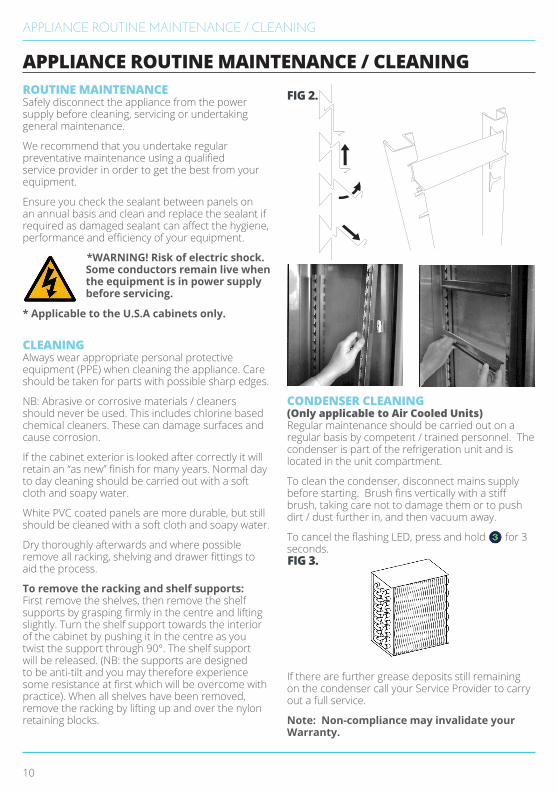
Dry thoroughly afterwards and where possible remove all racking, shelving and drawer fittings to aid the process.
To remove the racking and shelf supports: First remove the shelves, then remove the shelf supports by grasping firmly in the centre and lifting slightly. Turn the shelf support towards the interior of the cabinet by pushing it in the centre as you twist the support through 90°. The shelf support will be released. (NB: the supports are designed to be anti-tilt and you may therefore experience some resistance at first which will be overcome with practice). When all shelves have been removed, remove the racking by lifting up and over the nylon retaining blocks.
CONDENSER CLEANING(Only applicable to Air Cooled Units) Regular maintenance should be carried out on a regular basis by competent / trained personnel. The condenser is part of the refrigeration unit and is located in the unit compartment.
To clean the condenser, disconnect mains supply before starting. Brush fins vertically with a stiff brush, taking care not to damage them or to push dirt / dust further in, and then vacuum away.
To cancel the flashing LED, press and hold for 3 seconds.
If there are further grease deposits still remaining on the condenser call your Service Provider to carry out a full service.
Note: Non-compliance may invalidate your Warranty.
FIG 2.
FIG 3.
APPLIANCE ROUTINE MAINTENANCE / CLEANING

11
APPLIANCE ROUTINE MAINTENANCE / CLEANING
REMOVING THE UNIT COVERRemove the screws in the top and bottom edge of the unit cover and pull the unit cover away from the unit and retaining clips.
CLEANING / REPLACING THE GASKETDoor gaskets should be checked and cleaned regularly and replaced if damaged. To clean the gasket, wipe with warm soapy water and a soft cloth, ensuring it is completely dry before closing the door. DO NOT use a sharp knife to clean or scrape the gasket. Damaged gaskets do not seal correctly and can increase the amount of electricity consumed, seriously affecting the efficiency and performance of the appliance.
Damaged gaskets are easily replaced. Simply pull out the existing part and push the new gasket into the channel (gasket retainer) at the centre and work along, pushing gasket into channel.
EVAPORATOR/DRAINLINEInspect periodically to ensure the drain hole is not blocked.
BREAKDOWNIn the event of a breakdown, please contact Williams Refrigeration or your Service Provider
When calling, please advise model and serial number. This information can be found on the data plate inside the appliance. It should also be noted on the cover of this Manual. Please ensure that all redundant parts are disposed of safely and legally.
ENERGY INFORMATIONThe following information only applies to Reach-In Models.Model(s): WBCF10Type of Product: Blast Chiller / FreezerRefrigerant Fluid(s): R404A GWP: 3922Blast Chill Cycle: YESBlast Freeze Cycle: YES
ITEM Symbol Value UnitEnergy Consumption for Chilling Function E 0.152 kWh/kgChilled Full Load Capacity 10 kgEnergy Consumption for Freezing Function E 1.7 kWh/kgFrozen Full Load Capacity 1.238 kgRefrigerant Charge 0.825 kgBlast Chilling Cycle from +65°C to +10°C t 99 minBlast Chilling Cycle from +65°C to -18°C t 179 min
Contact Details: Williams Refrigeration, 9 Bryggen Road, North Lynn Industrial Estate, King’s Lynn, Norfolk. PE30 2HZ

12
ENERGY INFORMATIONThe following information only applies to Reach-In Models.Model(s): WBCF20Type of Product: Blast Chiller / FreezerRefrigerant Fluid(s): R404A GWP: 3922Blast Chill Cycle: YESBlast Freeze Cycle: YES
ITEM Symbol Value UnitEnergy Consumption for Chilling Function E 0.108 kWh/kgChilled Full Load Capacity 20 kgEnergy Consumption for Freezing Function E 0.878 kWh/kgFrozen Full Load Capacity 5 kgRefrigerant Charge 1.4 kgBlast Chilling Cycle from +65°C to +10°C t 77 minBlast Chilling Cycle from +65°C to -18°C t 244 min
Contact Details: Williams Refrigeration, 9 Bryggen Road, North Lynn Industrial Estate, King’s Lynn, Norfolk. PE30 2HZ
Model(s): WBCF30Type of Product: Blast Chiller / FreezerRefrigerant Fluid(s): R404A GWP: 3922Blast Chill Cycle: YESBlast Freeze Cycle: YES
ITEM Symbol Value UnitEnergy Consumption for Chilling Function E 0.12 kWh/kg
30 kgEnergy Consumption for Freezing Function E 1.202 kWh/kgFrozen Full Load Capacity 5 kgRefrigerant Charge 2.05 kgBlast Chilling Cycle from +65°C to +10°C t 78 minBlast Chilling Cycle from +65°C to -18°C t 219 min
Contact Details: Williams Refrigeration, 9 Bryggen Road, North Lynn Industrial Estate, King’s Lynn, Norfolk. PE30 2HZ
Model(s): WBCF40Type of Product: Blast Chiller / FreezerRefrigerant Fluid(s): R404A GWP: 3922Blast Chill Cycle: YESBlast Freeze Cycle: YES
ITEM Symbol Value UnitEnergy Consumption for Chilling Function E 0.096 kWh/kgChilled Full Load Capacity 40 kgEnergy Consumption for Freezing Function E 1.372 kWh/kgFrozen Full Load Capacity 5 kgRefrigerant Charge 2.05 kgBlast Chilling Cycle from +65°C to +10°C t 100 minBlast Chilling Cycle from +65°C to -18°C t 231 min
Contact Details: Williams Refrigeration, 9 Bryggen Road, North Lynn Industrial Estate, King’s Lynn, Norfolk. PE30 2HZ
ENERGY INFORMATION

13
Model(s): WBCF50Type of Product: Blast Chiller / FreezerRefrigerant Fluid(s): R404A GWP: 3922Blast Chill Cycle: YESBlast Freeze Cycle: YES
ITEM Symbol Value UnitEnergy Consumption for Chilling Function E 0.078 kWh/kgChilled Full Load Capacity 50 kgEnergy Consumption for Freezing Function E 0.6785 kWh/kgFrozen Full Load Capacity 20 kgRefrigerant Charge 3 kgBlast Chilling Cycle from +65°C to +10°C t 109 minBlast Chilling Cycle from +65°C to -18°C t 270 min
Contact Details: Williams Refrigeration, 9 Bryggen Road, North Lynn Industrial Estate, King’s Lynn, Norfolk. PE30 2HZ
Model(s): J1BCType of Product: Blast ChillerRefrigerant Fluid(s): R134A GWP: 1430Blast Chill Cycle: YESBlast Freeze Cycle: NO
ITEM Symbol Value UnitEnergy Consumption for Chilling Function E 0.1 kWh/kg
20 kgEnergy Consumption for Freezing Function E kWh/kgFrozen Full Load Capacity kgRefrigerant Charge 2.1 kgBlast Chilling Cycle from +65°C to +10°C t 108 minBlast Chilling Cycle from +65°C to -18°C t min
Contact Details: Williams Refrigeration, 9 Bryggen Road, North Lynn Industrial Estate, King’s Lynn, Norfolk. PE30 2HZ
Model(s): J1BCFType of Product: Blast ChillerRefrigerant Fluid(s): R404A GWP: 3922Blast Chill Cycle: NOBlast Freeze Cycle: YES
ITEM Symbol Value UnitEnergy Consumption for Chilling Function E 0.1 kWh/kgChilled Full Load Capacity kgEnergy Consumption for Freezing Function E 1.052 kWh/kgFrozen Full Load Capacity 5 kgRefrigerant Charge 1.8 kgBlast Chilling Cycle from +65°C to +10°C t minBlast Chilling Cycle from +65°C to -18°C t 270 min
Contact Details: Williams Refrigeration, 9 Bryggen Road, North Lynn Industrial Estate, King’s Lynn, Norfolk. PE30 2HZ
ENERGY INFORMATION

14
PARTS & LABOUR WARRANTY POLICY - UK ONLYOur warranty applies to equipment manufactured by Williams Refrigeration and equipment bearing the Williams name plate and serial number identification tag.
We undertake, in conjunction with the supplying agent, distributor or representative, to repair free of charge during our standard business hours any such piece of equipment or part thereof used which is found to be faulty in either materials or workmanship subject to the further conditions below:-
WARRANTY TERMS AND PRODUCTS COVEREDWe offer a 24 months Warranty from our original date of sale with the following Williams equipment:
1. Garnet / Sapphire / Zircon / Jade / Amber (stainless) / Mobile Heated/ Mobile Refrigerated.
2. Reach-in Blast Chillers / Reach-in Blast Chiller Freezers.
3. Opal / Emerald / Onyx / Aztra / Salad Counters.
4. Crystal Bakery Cabinets and Counters.
We offer a 12 months Warranty from our original date of sale for all other Williams equipment including:
1. All Modular Products (including coldrooms).
2. Remote Systems (including glycol).
3. Bottle Coolers.
4. Multidecks and merchandiser cases.
5. GEM product range.
6. Bottle Well / Meat Freezer Well.
7. Thermowell.
8. Non standard and other products.
9. Front of House display cases.
10. White Goods.
WARRANTY TERMSOur warranty is offered where the equipment has been installed correctly and has not been subject to misuse or abuse and is functioning correctly.
The equipment was purchased by the authorised supplying distributor direct from Williams Refrigeration and not through a wholesaler or other supplier whose warranty terms may be different.
The Warranty Policy shall be non-transferable.
Replacement of defective equipment can only be made with the approval of Williams Refrigeration.
Any repair under warranty will only be carried out with the product in its position of operation or in a suitable location on the customer’s premises. If the product has to be removed for security or any other reason, this will be subject to additional charge (may include hydrocarbon charged equipment).
Warranty work will be covered by Williams Refrigeration or by one of its appointed service agents between the hours of 8.00am and 5.00pm Monday to Friday. Any works undertaken outside of these hours are chargeable.
CLAIMS PROCEDUREIf a customer wishes to make a claim under the terms of this warranty, the following procedure should be observed:
1. Contact the supplying agent, representative or distributor.
2. Quote the equipment model, serial number and date of installation. The serial number is located on the product identification plate inside the cabinet, modular product door frame or similar location. It is recommended that operators should also record the serial number on the operating instruction booklet supplied with the product.
3. Contents risk and insurance responsibility remains at all times with the customer.
EXCEPTIONS TO STANDARD WARRANTIES1. The Standard warranty applies to equipment
located in Mainland GB only and excludes locations subject to restricted or secure access,offshore and marine applications. Additional time and travel charges may be applied to the following locations – Isle of Wight, Channel Islands, Isle of Man, Northern Ireland and Scottish Isles.
WARRANTY

15
2. Any fault that is not reported within 10 working days of being discovered.
3. Service calls to equipment under warranty, or service calls made under chargeable arrangements will be carried out in accordance with standard conditions of sale. Unless otherwise specified, a maximum of 15 minutes of administrative time, not spent directly carrying out servicing work, is provided for within the supply. Any requirement for staff attending the call to spend greater time than 15 minutes due to administrative requirements, such as on waiting time or security clearance, or health and safety risk assessments, will be chargeable at our prevailing rate. We reserve the right to apply Time Travel & Call out charges if no fault is found with the product or access is either restricted or denied to our attending engineer.
4. No claim shall exceed the original selling price.
5. Claims for Food and / or contents stored in the equipment supplied (including pharmaceutical or other items) and any consequential loss how so ever arising are excluded under our warranty terms.
6. Components including gaskets, doors, drawers, handles, shelves, tray slides, all internal fixings, plug and lead, connectors, the outer shell, castors / legs, food probes, refrigerant and blockages as well as consumable items such as (but not limited to) batteries, fuses, light bulbs, printer cartridges, keys, glass and paper roll.
7. Equipment manufactured to the customers’ own design, Williams Refrigeration will not be liable for any defect, non performance or improper operation of the equipment arising from any drawing design or specification supplied by the customer, their representative or agent.
8. Second hand equipment.
9. The customer uses or installs the equipment in such a way that it exceeds its design envelope or operates the equipment at control parameters other than those provided as standard factory settings.
10. The customer fails to observe commonly accepted operating practices.
11. The customer has not properly cleaned or maintained the equipment or carried out necessary servicing, including cleaning of the condenser, in accordance with instructions, literature or directions issued by Williams Refrigeration. (Operating Instructions are supplied with all equipment but also available at www.williams-refrigeration.co.uk).
12. Equipment fails through improper installation by others, misuse, abuse, accidental damage, power loss or fluctuations, fire, flooding or acts of god.
13. Any third party item(s) connected to the equipment that may affect performance.
14. The customer permits persons other than those authorised by Williams Refrigeration to perform or affect repairs or adjustments to the equipment.
15. If authorised representatives of Williams Refrigeration are denied full and free rights of access to the equipment for inspection during normal business hours as previously stated.
16. If Repairs are made using spare parts or replacement items not supplied or preauthorised by Williams Refrigeration.
17. The initial equipment supply date shall apply for warranty validity for the subsequent supply of replacement of parts or products.
EXTENDED WARRANTYExtended Warranty offers the opportunity to protect your equipment (subject to conditions outlined) for an additional period of up to 5 years inclusive of original warranty periods.
Should you require Extended Warranty, state on your order or notify the Dealer or Williams Sales Manager at the time of purchase and they will be able to arrange it for you.
To ensure your Extended Warranty Policy remains valid, at least one maintenance / service visit per year must take place in years 2, 3, 4 and 5.
For further information or clarification please call 01553 817000 or email to [email protected] or write to Williams Refrigeration, Bryggen Road, King’s Lynn, Norfolk, PE30 2HZ
WARRANTY
16
Design Excellence : Cool Technology
www.williams-refrigeration.com
0349_OP_BCF Blast Chiller Freezer O&M (E) | Rev 13 | October 2016
Williams Refrigeration is a trading name of AFE Group Limited.Registered in England & Wales under Registered Number 3872673. Registered Office Address - Bryggen Road, North Lynn Industrial Estate, King’s Lynn, Norfolk, PE30 2HZ
Williams Refrigeration Australia38-42 Gaine RoadDandenong South, Victoria 3175AustraliaTel: +61 3 8787 4747 Fax: +61 3 8787 4787Email: [email protected]: www.williams-refrigeration.com.au
Williams RefrigerationBryggen RoadNorth Lynn Industrial EstateKing’s LynnNorfolk PE30 2HZSales Tel: +44 1553 817000 Sales Fax: +44 1553 817111Spares Tel: +44 1553 817017 Spares Fax: +44 1553 817020Email: [email protected]: www.williams-refrigeration.co.uk
Williams Refrigeration Hong KongUnit C, 12/F., Roxy Industrial Centre,58 - 66 Tai Lin Pai Road, Kwai Chung, New Territories, Hong KongTel: +852 2407 5422 Fax: +852 2407 3767Email: [email protected]: www.williams-refrigeration.com.hk
Williams Silver Frost2 rue Conventionnel Huguet23000 GUERETFranceTel: +33 5 55 52 27 88 Fax: +33 5 55 62 10 61Email: [email protected]: www.williams-silverfrost.com
Williams Refrigeration Dubai18th Floor Crown Plaza Commercial TowerSheikh Zayed Road, DubaiUnited Arab EmiratesTel: +971 4 311 7145 Fax: +971 4 332 8860Email: [email protected]