operating and diagnostic instructions for intelliteam sg ... · troubleshooting the intelliteam sg...
TRANSCRIPT

S&C IntelliRupter ® PulseCloser® Fault InterrupterOutdoor Distribution (15.5 kV, 27 kV, and 38 kV)
Instruction Sheet 766-552© S&C Electric Company 2008-2017, all rights reservedAugust 28, 2017
Section Page Section Page
IntroductionQualified Persons . . . . . . . . . . . . . . . . . . . . . . . . . . . . . 2Read this Instruction Sheet . . . . . . . . . . . . . . . . . . . . . . 2Retain this Instruction Sheet . . . . . . . . . . . . . . . . . . . . . 2Proper Application . . . . . . . . . . . . . . . . . . . . . . . . . . . . . 2Special Warranty Provisions . . . . . . . . . . . . . . . . . . . . . 2
Safety InformationUnderstanding Safety-Alert Messages . . . . . . . . . . . . . 3Following Safety Instructions . . . . . . . . . . . . . . . . . . . . 3Replacement Instructions and Labels . . . . . . . . . . . . . . 3
OverviewApplicable Software . . . . . . . . . . . . . . . . . . . . . . . . . . . 4Diagnostic Access . . . . . . . . . . . . . . . . . . . . . . . . . . . . 4
IntelliTeam SG System DiagnosisTeam Summary . . . . . . . . . . . . . . . . . . . . . . . . . . . . . . 5Team 1 . . . . . . . . . . . . . . . . . . . . . . . . . . . . . . . . . . . . . 6Team 1–Task and Coach Analysis . . . . . . . . . . . . . . . . 9Activity Monitoring—Task Operation . . . . . . . . . . . . . . 12Activity Monitoring—Contract Status . . . . . . . . . . . . . 13Activity Monitoring—Action Path . . . . . . . . . . . . . . . . . 15Activity Monitoring—Coach Activity . . . . . . . . . . . . . . 16Activity Monitoring—Feeder Nets . . . . . . . . . . . . . . . . 17Troubleshooting the IntelliTeam SG System . . . . . . . . 18Using IntelliLink® Setup Software to Locate Problems 19
Table of Contents
Operating and Diagnostic Instructions forIntelliTeam® SG Automatic Restoration System

2 S&C Instruction Sheet 766-552
Qualified Persons WARNING The equipment covered by this publication must be installed, operated, and maintained by qualified persons who are knowledgeable in the installation, operation, and maintenance of overhead electric power distribution equipment along with the associated hazards . A qualified person is one who is trained and competent in:
• The skills and techniques necessary to distinguish exposed live parts from non-live parts of electrical equipment .
• The skills and techniques necessary to determine the proper approach distances corresponding to the voltages to which the qualified person will be exposed .
• The proper use of the special precautionary techniques, personal protective equip-ment, insulating and shielding materials, and insulated tools for working on or near exposed energized parts of electrical equipment .
These instructions are intended only for such qualified persons . They are not intended to be a substitute for adequate training and experience in safety procedures for this type of equipment .
Read this Instruction Sheet
Thoroughly and carefully read this instruction sheet before programming, operating, or maintaining your S&C IntelliRupter PulseCloser Fault Interrupter. Familiarize yourself with the safety information on page 3. The latest version of this publication is available online in PDF format at sandc.com/Support/Product-Literature.asp
Retain thisInstruction Sheet
This instruction sheet is a permanent part of your S&C IntelliRupter PulseCloser Fault Interrupter. Designate a location where you can easily retrieve and refer to it.
Proper Application CAUTION
The equipment in this publication must be selected for a specific application . The application must be within the ratings furnished for the selected equipment .
Special Warranty Provisions
The standard warranty contained in S&C’s standard conditions of sale, as set forth in Price Sheet 150, applies to IntelliRupter® fault interrupter and its associated options except for the control group (the protection and control module and communication module) and S&C SpeedNet™ Radio, as applicable. For these devices the first paragraph of said warranty is replaced by the following:
(1) General: Seller warrants to immediate purchaser or end user for a period of 10 years from the date of shipment that the equipment delivered will be of the kind and quality specified in the contract description and will be free of defects of workmanship and material. Should any failure to conform to this warranty appear under proper and normal use within ten years after the date of shipment the seller agrees, upon prompt notification thereof and confirmation that the equipment has been stored, installed, operated, inspected, and maintained in accordance with recommendations of the seller and standard industry practice, to correct the nonconformity either by repairing any damaged or defective parts of the equipment or (at seller’s option) by shipment of necessary replacement parts.
Replacement control groups and S&C SpeedNet Radios provided by seller or repairs performed by seller under the warranty for the original equipment will be covered by the above special warranty provision for its duration. Replacement control groups and S&C SpeedNet Radios purchased separately will be covered by the above special warranty provision.
This warranty does not apply to major components not of S&C manufacture, such as batteries and communication devices, as well as hardware, software, resolution of protocol-related matters, and notification of upgrades or fixes for those devices. However, S&C will assign to immediate purchaser or end user all manufacturers’ warranties that apply to such major components.
Introduction

S&C Instruction Sheet 766-552 3
Safety Information
Understanding Safety-Alert Messages
There are several types of safety-alert messages which may appear throughout this instruction sheet as well as on labels and tags attached to the IntelliRupter PulseCloser Fault Interrupter. Familiarize yourself with these types of messages and the importance of the various signal words, as explained below
DANGER
“DANGER” identifies the most serious and immediate hazards that will likely result in serious personal injury or death if instructions, including recommended precautions, are not followed .
WARNING “WARNING” identifies hazards or unsafe practices that can result in serious personal injury or death if instructions, including recommended precautions, are not followed .
CAUTION
“CAUTION” identifies hazards or unsafe practices that can result in minor personal injury if instructions, including recommended precautions, are not followed .
NOTICE
“NOTICE” identifies important procedures or requirements that, if not followed, can result in product or property damage if instructions are not followed .
Following Safety Instructions
If you do not understand any portion of this instruction sheet and need assistance, contact your nearest S&C Sales Office or S&C Authorized Distributor. Their telephone numbers are listed on S&C’s website sandc.com Or call S&C Headquarters at (773) 338-1000; in Canada, call S&C Electric Canada Ltd. at (416) 249-9171.
NOTICE
Thoroughly and careful ly read this instruction sheet before operating your S&C IntelliRupter PulseCloser Fault Interrupter .
Replacement Instructions and Labels
If you need additional copies of this instruction sheet, contact your nearest S&C Sales Office, S&C Authorized Distributor; S&C Headquarters, or S&C Electric Canada Ltd.
It is important that any missing, damaged, or faded labels on the equipment be replaced immediately. Replacement labels are available by contacting your nearest S&C Sales Office, S&C Authorized Distributor, S&C Headquarters, or S&C Electric Canada Ltd.

4 S&C Instruction Sheet 766-552
Overview
This instruction sheet is used with IRInstaller-6.1.X. The “x” can indicate any number from 0 to 255. Other related software component version information is found on the Setup > General > Revisions screen. IRInstaller-6.1.X.exe is the name of the installer file available at the S&C Automation Customer Support Portal.
CAUTION
To prevent unexpected operation of a team member during manual reconfiguration of the circuit (for example, during repairs), follow your company’s operating procedures for disabling automatic operation of the IntelliTeam SG Automatic Restoration System .
You can disable the IntelliTeam SG system by selecting Restoration Prohibited on the IT SG Operation > General > Team Summary screen of any active team member .
You can access IntelliRupter fault interrupter for troubleshooting in several ways:
Visual inspectionIntelliRupter fault interrupter status can be determined on-site by observing the status light and the hot line tag indicator light, and by checking the manual lever positions.
Secure Wi-Fi connection with IntelliLink® Setup SoftwareYou can locally access configuration and operation screens and download historical data from IntelliRupter fault interrupter, using IntelliLink Setup Software running on your laptop computer.
Access IntelliRupter fault interrupter through SCADAWhen furnished with a suitable user-specified radio, you can remotely access configuration and operation screens and download historical data from IntelliRupter fault interrupter, over a SCADA system using DNP 3.0 Protocol.
Access through IntelliLink® Remote Setup SoftwareYou can remotely access configuration and operation screens and download historical data from IntelliRupter fault interrupter, using IntelliLink Remote Setup Software running on any personal computer connected to your DNP network. Settings may be changed, validated, and applied.
This instruction sheet provides instructions for diagnosing problems experienced with the IntelliTeam SG Automatic Restoration System, through the IntelliLink software Wi-Fi connection.
NOTICEIf the suggested diagnostic procedures do not resolve the problem, call S&C at (773) 338-1000 for assistance .
Applicable Software
Diagnostic Access

S&C Instruction Sheet 766-552 5
IntelliTeam SG System Diagnosis
This screen shows the Ready status, and Prohibit Restoration status of each team. If manual operation has been effected by a local lever, Wi-Fi, or SCADA, the team(s) will not be READY. Manual operation(s) can be cleared by clicking the Clear Manual Operation button.
All teams must be READY and IT SG Restoration Enabled must be active for the IntelliTeam SG system to operate. If an IntelliRupter fault interrupter has an unknown mechanism state, it will force its teams out of READY. See Instruction Sheet 766-550 for Alarms, Warnings, and Errors related to the IntelliRupter fault interrupter mechanism.
For individual team information, click on the tab for Team 1 through Team 8.
IntelliTeam SG System RestorationIntelliTeam SG system restoration can be either Enabled or Disabled. The slide bar shows the present restoration state. To change the restoration state, click the slide bar.
Site Acceptance Test (SAT)The Site Acceptance Test can be either Enabled or Disabled. The slide bar shows the present state of the Site Acceptance Test. To change the Site Acceptance Test state, click the slide bar.
SAT StatusShows present status of the Site Acceptance Test.
SAT VersionShows version number of the Site Acceptance Test script file loaded in the control.
Clear Manual OperationIf manual operation has been effected by a local lever, Wi-Fi, or SCADA, the team(s) will not be READY. Manual operation(s) can be cleared with the Execute button.
Figure 1. IntelliTeam SG System—Team Summary screen.
Select Left Menu: IntelliTeam SG > Team Summary. See Figure 1.Team Summary

6 S&C Instruction Sheet 766-552
IntelliTeam SG System Diagnosis
This screen shows the present status of various team-related parameters and information on each team member.
General Team Status
Team IDThis is the name entered in the Team ID set point on the SETUP: Team screen.
Local Real-Time LoadThe two-minute-averaged, three-phase load (in amperes) measured on the line segment protected by this team. It does not include load outside of the local line segment.
Real CapacityThe load capacity available on the line segment protected by this team. It takes into account the real capacity of source-side teams, the maximum capacity of the team’s present source device, and any load that has already been transferred during circuit reconfiguration.
Transfer StateThe present state of any transfer operations. Possible values are:
Idle—Team configuration is normal. No transfer or return-to-normal operations are taking place.
Init—Data is being collected from team members in preparation for a transfer event.
Rqst—The line segment is requesting service restoration from an adjacent line segment.
Grant—The line segment is being asked to grant service restoration to an adjacent line segment.
Wait—The team configuration is not normal. The team is waiting for additional circuit reconfiguration or return-to-normal operation.
RTN—Team is returning to normal configuration.
Stop—An error has occurred, stopping a transfer operation.
Fault—The team is presently isolating a fault.
Hold—The team has begun a transfer event but the line segment is not yet fully deenergized.
Team 1 Select Left Menu: IntelliTeam SG > Team 1. See Figure 2.
Figure 2. IntelliTeam SG System—Team 1 screen.

S&C Instruction Sheet 766-552 7
IntelliTeam SG System Diagnosis
Ready StatusIf Operational Status, Configuration Status, and Line Segment Status all indicate that no errors are present, READY appears in this field. If errors are present, ALARM appears. If the team is isolating a faulted line segment, FAULT appears.
Operational StatusThe operational status of the system. Possible values are:
Good—Team members can perform team operations.
Coordination—The team coach is not passing through the team, causing a lack of team coordination.
Remote Config—The configuration of an adjacent team member is not consistent with the configuration of this IntelliRupter fault interrupter.
Local Config—There has been a change to the local team configuration on the SETUP: Team screen that has not yet been accepted.
Remote Error—An adjacent team member is indicating an error condition.
Local Error—A local team member is disabled because Prohibit Restoration is on, or because the device has changed state from an IntelliLink software or SCADA operation.
Logic Disabled—Team logic has been disabled on the SETUP: Team screen.
Not In Use—This team is not in use.
No 2nd Contin.—The team is in a transferred state. If another event occurs, no further restoration activity is allowed.
Configuration StatusThe status of user-configured parameters essential for team operation. Possible values are:
NoRTU Addr—No RTU address was specified on the SETUP: Communications screen.
Stop + Data Chg—The “Team Setup” set point is in the “Stopped” state following a change made to the team parameters on the SETUP: Team screen.
Stopped—The “Team Setup” set point has been disabled on the SETUP: Team screen.
Data Change—An unexpected change has been made to the team parameters on the SETUP: Team screen.
Record Count—The count of team member records on the SETUP: Team screen is incorrect. The team database must have at least one record to be valid.
Not 1 Source—An incorrect number of source devices were configured on the SETUP: Team screen. A team may have only one source switch.
No Local Rec—No local record was found in the team database. One of the team records must contain an RTU address that matches the “DNP/RTU Address” entered on the SETUP: Communications screen.
Line Segment StatusThe status of the line segment protected by this team of IntelliRupter fault interrupters. Possible values are:
Good—No faults or voltage loss have been detected on the line segment.
Segment Dead (Dd)—The line segment is de-energized.
Segment Open (Op)—All team members are in the open position in preparation for a circuit reconfiguration.
Overcurrent (OC)—An overcurrent was detected on this line segment.
Voltage Loss (VL)—A voltage loss was detected on this line segment.
Team Error (Er)—An error has been detected.
Alt Source (AS)—The line segment is being fed by an alternate source, either directly from an adjacent line segment, or indirectly from another location.

8 S&C Instruction Sheet 766-552
IntelliTeam SG System Diagnosis
Individual Team Member Status
DNP/RTU Addr
The DNP/RTU address of each team member, as entered on the SETUP: Team screen.
Sw/Pos NumThe position number associated with the team member, for example “Sw1” for a single overhead switch, as entered on the SETUP: Team screen.
Normal StateThe state of each team member when the circuit is configured normally, as entered on the SETUP: Team screen.
Present StateThis is the present position of each team member:
Open—Team member is open.
Closed—Team member is closed.
---- —Position of team member is unknown, or the record is not in use. This is considered an error condition during normal operation.
Auto ModeThe automatic features enabled for each team member, as entered on the SETUP: Auto-matic Operation and SETUP: Team screens. Also indicates if team member has been temporarily placed in manual operation mode. A combination of values can be shown:
B—This switch has been temporarily Blocked from use as a valid source for the team during the reconfiguration event. This may be due to a subsequent loss of voltage at this switch, or this switch was used to shed load following a reconfiguration.
M—Team member has been temporarily placed in manual.
A—Automatic sectionalizing has been enabled.
V—Sectionalizing on loss-of-voltage only has been enabled.
T—Automatic transfer logic has been enabled.
P—Sectionalizing on Phase Loss has been enabled.
Ro—Return-to-normal logic using open transition has been enabled.
Rc—Return-to-normal logic using closed transition has been enabled.
Internal ErrorPossible values are:
None—No internal errors are present in a team member.
Trouble—A team member is disabled because of a bad battery or other condition.
NotAuto—A team member has been placed into a non-automatic condition.
ManOR—The open/close state of a team member has been manually overridden.
No Op—A close or open operation was requested but the team member was unable to perform the operation.
NOTE: ManOR and No Op status can be cleared on the Operation-General screen by clicking the Clear Manual Operation Execute button. They can also be cleared on the Team Sw. Errors screen, or with a SCADA command.
ProRes—The team member has been sent a “Prohibit Restoration” command.
S&C Instruction Sheet 766-552 9
IntelliTeam SG System Diagnosis
Event StatusThe present status of events related to this team member. A combination of values can be shown:
O—Latched on overcurrent event.
V—Latched on voltage loss, on any or all phases.
P—Latched on phase loss, sectionalizing event.
Vr—Real-time voltage loss, on any phase.
3Vr—Three-phase real-time voltage loss.
C—A team member is in cycling state.
Avg Load
This is a two-minute-averaged, three-phase load reported by each team member. It is used to determine the Local Real-Time Load. After an event, it is frozen at the last value reported before the event began, thus ensuring that the team uses pre-event values during the transfer. The value is not updated until the transfer is completed.
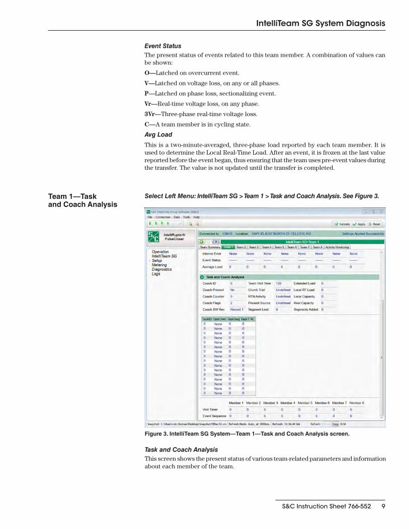
Figure 3. IntelliTeam SG System—Team 1—Task and Coach Analysis screen.
Team 1—Task and Coach Analysis
Select Left Menu: IntelliTeam SG > Team 1 > Task and Coach Analysis. See Figure 3.
Task and Coach AnalysisThis screen shows the present status of various team-related parameters and information about each member of the team.

10 S&C Instruction Sheet 766-552
IntelliTeam SG System Diagnosis
Coach IDIdentification number of the present team coach. If the coach is lost, the next coach generated has a higher ID number.
Coach PresentIndicates that the team coach is present at this team member, and shows the status of the coach.
Coach CounterThis ongoing count of times the present coach has arrived at team members. Along with the Coach ID, it is used to validate the coach when it is received.
Coach FlagsIndication that the coach has arrived and left this team member. It shows that the team data has been refreshed.
Coach Sw RecIndicates where the coach, if present at this team member, is executing.
Team Visit TimeIndicates the remaining time (in seconds) before a new coach is generated. This timer is refreshed while the coach is present. If the coach does not return, and the timer expires, this team member will generate a new coach.
Crumb TrailA database record allowing team functions to span multiple teams. Provides a path back to the originating team.
RTN ActivityA database record indicating where the return-to-normal process originated.
Present SourceA database record for the team member through which the line segment is presently receiving power.
Segment LimitThe number of line segments allowed to be restored on this circuit. It is the lesser of the limit configured in the Line Segment Limit setpoint on the SETUP: Team screen and the limits set in adjacent source-side teams.
Extended LoadThe extended loading of the team, including the loading of the line segment and all downstream load.
Local RT LoadThe local real-time load on the line segment protected by this team. It is the same as the Local Real-Time Load on page 1 of the Team Operation screen.
Local CapacityThe loading capacity of the local team. This value is compared with the remote capacity of the adjacent source-side team to determine the real capacity of the team.
Real CapacityThe loading capacity available on the line segment protected by this team. It is the same as the Real Capacity on page 1 of the Team Operation screen.
Segments AddedThe number of segments presently added. The team compares this value to the Line Segment Limit on the SETUP: Team screen when a transfer event occurs.

S&C Instruction Sheet 766-552 11
IntelliTeam SG System Diagnosis
The table in the center of the screen shows tasks that are presently being executed. This information is used for diagnostic purposes by S&C.
TaskIDIdentification of the task being executed.
TaskOwnIndicates the team in which the task is being executed. The task may require global execution at all team members.
TaskSeqThe sequence number of the task being executed.
TaskTTRThe time-to-run of the task being executed.
The table at the bottom of the screen (see Figure 3 on page 9) shows database records for all members of the team.
Visit TimerIndicates the remaining time (in seconds) before the coach should visit a specific team member. The timer is carried by the coach and will only update while the coach is at the team member.
Event SequenceThis is the sequence number of the last event received from this team member.

12 S&C Instruction Sheet 766-552
IntelliTeam SG System Diagnosis
Figure 4. IntelliTeam SG System Activity Monitoring—Task Operation screen.
Activity Monitoring—Task Operation
Select Left Menu: IntelliTeam SG Activity Monitoring > Task Operation. See Figure 4.
Task OperationThis screen shows tasks that are presently being executed by a particular team member. The information is used for diagnostic purposes by S&C.
IDIdentification of the task being executed.
OwnTeam database record associated with the execution of this task.
SeqSequence number of the task being executed.
TTRTime-to-run of the task being executed.
AttribLock and execute attributes associated with the task being executed.
TEAMTeam number associated with execution of this task.

S&C Instruction Sheet 766-552 13
IntelliTeam SG System Diagnosis
Figure 5. IntelliTeam SG System Activity Monitoring—Contract Status screen.
Activity Monitoring—Contract Status
Select Left Menu: IntelliTeam SG Activity Monitoring > Contract Status. See Figure 5.
Contract StateThis field shows the present state of the contract. Possible values are:
Active—The contract has been granted and is presently active.
Rqst unsent—The contract agent received a contract request from the team member, but has not yet sent the request to the next contract agent.
Rqst pending—The contract request is pending.
Rqst travel—The contract agent is forwarding the contract; the decision to grant the contract cannot be made at this location.
Rqst accept—The contract request was accepted by this agent; contract approval is headed back to the originating agent. When this message appears at the granting agent, the contract has been approved.
Rqst decline—The contract request was declined by this agent. The request will be sent back to the originating agent.
Decline cont.—A declined message is being passed to the requesting agent.
Dissolve start—An agent (generally the requesting agent) is dissolving the contract.
Dissolve cont.—A dissolve message is being passed.
Maint start—The maintenance timer on an active contract has expired, causing a maintenance action to occur.
Maint tickle—The contract agent has not seen a maintenance message for the contract lately, and has sent a reminder to the requesting agent to see if the contract is still needed.
Maint travel—A maintenance message is being passed from the requesting agent to other agents along the contract route.
Maint tra NF—The contract agent has received a maintenance message for a contract that is not found in its list.
Maint tra NF rt—A Maint tra NF message is being returned to the requesting agent. This message can also appear at other agents along the contract route.

14 S&C Instruction Sheet 766-552
IntelliTeam SG System Diagnosis
Maint tic NF—The contract agent has received a “tickle” message for a contract that is not found in its list.
Maint tic NF rt—A “Maint tic NF” message is being returned to the agent that initiated the tickle. This message can also appear at other agents along the contract route.
Maint restart—The requesting agent has confirmed that it still needs the contract. The maintenance timer is restarted.
Maint res cont.—A “restart” message is being passed to other agents along the contract route.
Rqst AgentThe agent that requested the contract.
Grant AgentThe agent that approved the contract.
Orig SegmtThe database record number for the segment where the contract request originated.
Temp SegmtThe database record number for the present location of the contract request.
Line CountThe number of line segments that will be picked up if the contract request is granted. This value is generally “1.”
Load RqstThe amount of load that will be picked up if the contract request is granted.
Maint TimerAfter a contract request is granted, the time remaining before contract maintenance should be performed. When a contract is no longer needed, the requesting agent sends a message to dissolve the contract. If the local contract agent does not receive a response within the timer setting, it checks with the requesting agent.
The requesting agent can extend the contract if it is still needed, or dissolve the contract if it is no longer needed.
Rqst TimeThe date and time when the contract was requested.

S&C Instruction Sheet 766-552 15
IntelliTeam SG System Diagnosis
Figure 6. IntelliTeam SG System Activity Monitoring—Action Path screen.
Activity Monitoring—Action Path
Select Left Menu: IntelliTeam SG Activity Monitoring > Action Path. See Figure 6.
Action Path
This screen tabulates the actions taken during execution of a team member operation. The information is used for diagnostic purposes by S&C.
Backing out of an action path may occur when one of the steps cannot be performed, therefore requiring that the team member be put back to its normal state.
DirectionThe direction that the action path is presently taking. Reverse will only occur if the forward path is stopped before completion.
Action Item PointerA record within the action path that is presently being executed, used for diagnostic purposes by S&C.
Forward Action /Reverse ActionName of the step that will be taken during execution of the action path, and the time stamp at the start of that step. Step names that may be displayed include:
Action path done
Close for xfer
Contract request
Contract terminate
Block recloser
Unblock recloser
Block ground trip
Unblock ground trip
Alternate settings
Normal settings
StatusStatus of the associated step in the action path, and the relative time at which this step occurred. The status can be: Idle, Running, Failed, or Success.

16 S&C Instruction Sheet 766-552
IntelliTeam SG System Diagnosis
Figure 7. IntelliTeam SG System Activity Monitoring—Coach Activity screen.
Activity Monitoring—Coach Activity
Select Left Menu: IntelliTeam SG Activity Monitoring > Coach Activity. See Figure 7.
Coach Activity
This screen shows timestamps for basic coach activities, as well as the counter for each team’s coach. It includes the following:
NumberThe coach/team number.
In-Out StatusThe coach activity: signing in, or going to the specified team member (Rec 1, Rec 2, etc.).
Time StampThe date and time when the activity occurred.
Sign-In CountsThe ongoing counts for each team’s coach.

S&C Instruction Sheet 766-552 17
IntelliTeam SG System Diagnosis
Figure 8. IntelliTeam SG System Activity Monitoring—Feeder Nets screen.
Activity Monitoring—Feeder Nets
Select Left Menu: IntelliTeam SG Activity Monitoring > Feeder Nets. See Figure 8.
Feeder NetsThis screen contains data associated with the Feeder Netlists.
Feeder CategoryThe FeederNet is a database of the Teams and Controls/switches that use one breaker at a substation (or equivalent source) as their primary power source.
Primary 1—Every switch has a Primary 1 FeederNet, associated with its primary sub-station breaker.
Primary 2—Only a tie point control will have a Primary 2 FeederNet, that is associated with the adjacent substation breaker for this tie point.
Adjacent—This is the FeederNet on the other side of the tie. They are listed for every tie point on the Primary feeder. There will generally be as many Adjacent FeederNets listed as there are alternate sources for the Primary feeder.
FeederNet IDThe unique identifier assigned by IntelliTeam® Designer, that defines a specific substa-tion breaker (or equivalent) and the circuit it supplies out to the end loads and/or open tie points.
FeederNet CRCThe CRC is a value calculated for a specific FeederNet configuration. The CRC changes when any FeederNet data is changed. It is used to identify a specific FeederNet configu-ration version.
Reset Feeder NetsThis command clears the stored Feeder Net data. When this is cleared you must push a new Feeder NetList.

18 S&C Instruction Sheet 766-552
IntelliTeam SG System Diagnosis
Troubleshooting IntelliTeam SG System
Check the following at each team member, starting at the most likely team member.
Team does not communicateSTEP 1. Setup > Communications screen settings. Verify that the baud rates, RTS
active durations, and duplex settings are correct for the radio installed.
STEP 2. Radio antenna. Verify that the radio antenna is in place and that the antenna cable is attached at both ends.
STEP 3. Radio connectivity. Verify that the radio recognizes all the other radios it should see. Refer to the manufacturer’s documentation.
Team does not reconfigure the circuitSTEP 1. Team logic set point. Connect to IntelliRupter fault interrupter via Wi-Fi and
start the IntelliLink software. On the Setup > Restoration > IntelliTeam II screen, verify that the Team Logic set point is enabled for this team.
STEP 2. Other Setup > Restoration > IntelliTeam SG screen settings. Verify that the DNP/RTU Address is correct for each team member. Verify that the Normal Open/Close set point is correct for each team member. Verify that the Normal Sw Func set point is correct. Verify that the Maximum Capacity settings are appropriate for the circuit conditions.
STEP 3. Values on the IntelliTeam SG Operation > Basic screen. Verify that the Ready Status reads READY. Check Operational Status, Line Status, and Configuration Status for reasons that the team is not ready.
STEP 4. Team communication. See “Team does not communicate” above.
STEP 5. Circuit configuration. Verify that the circuit has not been temporarily reconfigured due to construction or maintenance.
STEP 6. An event was logged. Check the Logs > Historic Events screen to see if the team member detected and took action on an event.
Team does not return the circuit to normalSTEP 1. Return to Norm Mode set points. On the Setup > Restoration > IntelliTeam
SG > Team 1 through Team 8 screens, verify that the “Rtn to Norm Mode” open or closed set point is set properly for this team.
STEP 2. Present state of each team member. On the IntelliTeam SG Operation > General > Team Summary screen, verify that the Ready Status reads READY. Check Operational Status, Line Segment Status, and fields on the IntelliTeam SG Operation > General > Team 1 through Team 8 screens for reasons that the team may not be ready.
STEP 3. Team communication. See “Team does not communicate” above.
STEP 4. Automatic operation. If automatic operation was disabled at any team member while the circuit was in its reconfigured state, the Return to Normal process is canceled.
Operation screen shows “ALARM” or “FAULT”IntelliTeam SG Operation > General > Team 1 through Team 8 screens. Check Operational Status, Line Status, and Configuration Status for reasons that the team is not ready.
DNP communication between your computer and team members is not working
STEP 1. Team communication. See “Team does not communicate” above.
STEP 2. Protocol and DNP address used by the IntelliLink software. Start the IntelliLink software on your computer. Select Tools > Options > Communication Setup. Check that DNP is the selected protocol. Check that the Peer Address matches the “DNP/RTU Address” for the team member with which you are trying to communicate. Check that timeout and baud rate are set appropriately.
STEP 3. Check for error messages. See the Logs > Historic Events screen.

S&C Instruction Sheet 766-552 19
IntelliTeam SG System Diagnosis
SCADA commands are ignored by IntelliRupterSTEP 1. RTU address. On the Setup > Communications > Comm. Setup > General
screen, check the Local Device RTU Address used by this IntelliRupter fault interrupter. Make sure the SCADA master station is sending commands to the correct address.
STEP 2. Radio operation. See the manufacturer’s documentation for details.
The Operation, IntelliTeam SG General, and Diagnostics screens can help you check the present status of:
• This IntelliRupter PulseCloser Fault Interrupter
• Other team members
• Team operations
These screens can also help you locate the cause of various team and team member problems.
Using IntelliLink Setup Software toLocate Problems
