operating & maintenance instructions the - c r clarke
TRANSCRIPT

The Thermoforming Centre 911 Inst Issue 2, June 2007
Operating & Maintenance Instructions The Thermoforming Centre 911 Table of Contents 1. Getting Started................................................................................................................................................2
2. Thermoforming Centre Components ..............................................................................................................5 2.1 Overview .................................................................................................................................................. 5
2.2 Machine Components .............................................................................................................................. 6 2.3 Main Control Panel................................................................................................................................... 6
2.3 Main Control Panel.................................. ............................................................................................... 7 2.4 Oven/Vacuum Forming & Injection Mould ng/Extrusion Control Panels.................................................. 8
2.5 Setting the Timer (old style timer) ........... ............................................................................................... 9 2.6 Setting the Timer (new style timer) .........
3. Vacuum Forming ..........................................
4. Dome Blowing...............................................
5. Plastic Dip Coating .......................................
6. Injection Moulding.........................................
7. Extrusion.......................................................
8. Welding.........................................................
9. Press Forming ..............................................
..
i
..
1
............................................................................................... 10
................................................................................................11
................................................................................................13
................................................................................................21
................................................................................................25
................................................................................................29
................................................................................................32
................................................................................................36

The Thermoforming Centre 911 Inst Issue 2, June 2007
2
1. Getting Started
Safety Guidelines
Safety is a very important issue in the thermoforming environment. Thermoforming uses heat, electricity and pressure to mould and form thermoplastics in different ways; heat, electricity and pressure can cause injuries and need to be understood before attempting to work with them.
Wear Heat Proof Gloves During Extrusion/Injection Moulding
Crucibles and injection moulds have a high thermal mass and when they are hot they stay hot. Therefore heat proof gloves should be worn whilst handling the crucibles (even if the crucible handling fork is being used) during and (for at least 20 minutes) after extrusion or injection moulding has taken place.
Avoid Contact with Hot Areas
During operation, various areas and surfaces will become hot enough to burn the skin if touched. Be wary of any part of the machine close to the heaters (the heater hood is painted red), parts that are in or have been in the oven and only handle the welding torch by its handle.
Take Care When Opening Oven Door
Keeps clear of the oven when opening its door during operation, to avoid burns from escaping hot air.
Do Not Overfill Dip Coating Tank
The thermoplastic powder in the dip coating tank will expand by 10-20% during fluidisation. It should be filled no more than two thirds to three quarters full to prevent spillage during fluidisation. Start the fluidisation process with the air flow control valve fully closed and open it gradually until there is enough fluidisation to allow a component to touch the bottom of the tank with no resistance (test this with a cold piece).
Wear Protective Gloves When Using the Welding Knife
The welding knife is extremely sharp and dangerous. It should be used only for cutting off lengths of welding rod from the coil and trimming excess welding rod from welded parts. Protective gloves should be worn to protect the hands and fingers.
Look After the Air Seals
There are 4 main seals, 2 on the vacuum forming plates, 1 on the bottom of the dome blowing plate and 1 on the bottom of the dip coating tank. Check these seals regularly and make sure that they are firmly attached and not compressed. If they are either of these things, contact your supplier.
Know your Machine Tool
Read this guide carefully before you use the Thermoforming Centre and keep it readily accessible for quick reference. Know the intended applications and limitations of the Thermoforming Centre as well as its hazards.
The Thermoforming Centre 911 Inst Issue 2, June 2007
3
Ground All Tools
The Thermoforming Centre has an AC power cord terminated by a three-prong plug. The power cord should be plugged into a three-hole, grounded receptacle. If a grounding adapter is used to accommodate two-prong receptacle, the adapter wire must be attached to a known ground. Never remove the third prong from the plug on the AC power cord.
Keep the Work Area Clean
Cluttered work areas and bench tops invite accidents.
Avoid a Dangerous Environment
Don’t use the Thermoforming Centre in damp or wet locations. Never operate electrical equipment in the presence of volatile and flammable petroleum -based solvents and lubricants.
Keep Untrained Visitors Away from the Equipment
Children, and visitors unfamiliar with the hazards of ceramic heaters and molten plastics, should always be kept away from the work area.
Prevent Unauthorised Users from Operating the Thermoforming Centre
Lock and remove the key from the Thermoforming Centre control panel (if fitted) and storage cupboard when the system is not in use.
Do Not Force Components
Excessive force is not needed to perform any Thermoforming Centre operation. Test and become familiar with, the various forces required for lifting the platen, moving the heater hood, opening the oven door, etc., and if you then encounter unusual resistance during operation, find the cause of the obstruction and remove it before proceeding (the most common cause of undue resistance is the platen locked in the raised position whilst trying to remove the dome blowing plate).
Use the Right Material
Make sure that you are using the correct material for the job. You cannot, for example, weld Acrylic with the Hot Air Welding Torch; this will only weld Polypropylene, PVC or ABS. Nor can you blow symmetrical domes with Polystyrene sheet, or extrude Polyethylene powder. Refer to the relevant sections in this manual when choosing materials.
Dress Appropriately
Don’t wear loose clothing or jewellery which can get caught in moving parts. Wear a hat or net, or tie your hair back to keep it away from moving parts. Wear long sleeved shirts or workshop overalls, as the sleeves can prevent burns to the arms from inadvertent contact with hot surfaces.
Secure the Work piece
Make sure that all toggle clamps, clamp frames, injection moulds, vacuum forming moulds, crucibles and components are sitting in their proper positions and locked down (if appropriate) before performing any process relevant to them.

The Thermoforming Centre 911 Inst Issue 2, June 2007
4
Do Not Overreach
Keep your footing and balance at all times so you won’t fall onto or grab at the hot parts of the Thermoforming Centre.
Adjust Toggle Clamps
Make sure that the toggle clamps on the Vacuum Forming clamp frame and the Dome Blowing plate are adjusted correctly for the thickness of material that you are using.
Do Not Operate the Centre Under the Influence of Alcohol or Drugs
Alcohol or drugs may impair your judgment and reaction time, which could cause accidents.
Avoid Distractions While Running the Machine
Use simple common sense and pay attention while operating any piece of machinery.

The Thermoforming Centre 911 Inst Issue 2, June 2007
5
2. Thermoforming Centre Components 2.1 Overview
What is the Thermoforming Centre 911?
The Thermoforming Centre 911 is a machine which performs seven thermoforming functions on a number of thermoplastic materials:
• Function Materials
• Welding Polypropylene, PVC, ABS
• Vacuum Forming Polystyrene, Extruded Acrylic, PVC, ABS, Polycarbonate, Polypropylene, Polyethylene
• Dome Blowing Cast Acrylic, PVC
• Dip Coating Nylon, Polyethylene, Polypropylene
• Injection Moulding Nylon, Polyethylene, Polystyrene
• Extrusion Polystyrene
• Press Forming Cast Acrylic, ABS, PVC
All of these processes require heat and pressure, which are provided by the Centre’s ceramic heater system (except the welding torch which has its own heat source) and vacuum pump. The heaters are used to provide ambient heat in the temperature controlled, fan circulated oven or to provide radiant heat for the vacuum forming facility. The vacuum pump provides appropriate air pressures to the different functions when they are selected by the process selector switch (PSS) on the main control panel.
Each material has an optimum heating time depending on its form, heating characteristics and thickness and a digital set timer is incorporated on the main control panel to assist in achieving correct heating times.
A working knowledge of the properties of thermoplastics is necessary in order to use the machine effectively and it is recommended that students familiarise themselves with technical data on thermoplastics before attempting to use the Thermoforming Centre.

The Thermoforming Centre 911 Inst Issue 2, June 2007
6
2.2 Machine Components
The Welding torch and welding rod are mounted on a Welding rod cassette & dispenser and there is a Welding torch holster for when the torch is in use. Welding is carried out on the Folding work table with adjustable angle stop. Vacuum forming and dome blowing plates slide in and out of the Vacuum forming, dome blowing and dip coating location when the platen is lowered (ie. when the Platen elevating handle is near the vertical). The dip coating tank is taken out of the Storage point for dip coating tank and clamped in the large vacuum forming plate for dip coating.
The Heater can be moved over the vacuum forming plate for radiant heating during vacuum forming. The Injection moulding and extrusion controls control the direction (up and down) and the speed of the ram mounted on the Pneumatic power cylinder. The Water tube should be filled before extrusion. The Vacuum forming/oven selector switch determines whether the ceramic heaters are controlled by the Oven temperature controller (in which case they will cycle to maintain set oven temperature) or the Vacuum forming controls.
The appropriate air supply is delivered when the Process selector switch (PSS) is turned to the relevant process. The unit’s Mains isolation, circuit breakers and fuse are found on the left of the main control panel.
The Timer is controlled manually and sounds an alarm at the end of a set cycle. There is a lockable Storage cupboard for accessories, components and materials, and Lockable castors for easy mobility.
Process selector switch (PSS)Vacuum forming,dome blowing & dip
coating location
Mains isolation
Circuit breakers
Fuse
Platen elevating handle
Folding work table
Welding torch holster
Welding rod cassette & dispenser
Welding torch
Heater
Pneumatic power cylinder
Injection moulding & extrusion controls
Vacuum forming/ oven selector
Oven temperature controller
Water tube
Storage point for dip coating tank
Storage cupboard
Lockable castors
Vacuum forming controls
Timer

The Thermoforming Centre 911 Inst Issue 2, June 2007
7
2.3 Main Control Panel
1. Mains power indicator light. Illuminated green when power is available to the machine.
2. Mains power switch and no volt release. 1 is the on position, 0 is the off position. Illuminated orange when the machine is on. If there is an interruption to the electrical supply, this switch automatically returns to the off (0) position and will need to be manually reset.
3. Vacuum pump, Heater and Welding torch circuit breakers. If any of these systems encounter a power overload, the breaker will pop out to protect the circuit. To reset, push back into the control panel. If breakers are popping frequently, contact your supplier.
4. Control Fuse. If power is available to the machine but, it cannot be turned on, check this fuse first by unscrewing it from the control panel. Replace with 1A-F (spares supplied with machine).
5. Process selector switch (PSS). Delivers the appropriate air supply for each process and provides two off positions.
6. Timer. See ‘Setting the Timer’.
7. Timer cancel button. Cancels the timer at any point during its cycle.
8. Timer start button. Starts the timer.
9. Vacuum forming heater power controls. The heater power for the vacuum forming facility is separated into outer and inner heating zones. Each zone has a rotary power controller which increases or reduces the amount of heat emitted. For most vacuum forming processes the heaters will be run on full power. NB These controls only work when Vacuum Forming is selected on the Oven/Vacuum Forming Control Panel (See Oven/Vacuum Forming & Injection Moulding/Extrusion Control Panels later).
10. Heater power indicator lights. Illuminated orange when there is power to the heaters (and the unit is in Vacuum Forming mode).

The Thermoforming Centre 911 Inst Issue 2, June 2007
8
2.4 Oven/Vacuum Forming & Injection Moulding/Extrusion Control Panels
1. Vacuum forming mode indicator light. Illuminated orange during vacuum forming
mode (ensure that the oven is empty).
2. Mode selector switch. Selects either vacuum forming or oven mode.
3. Temperature controller. Controls and displays the temperature in the oven when Oven is selected by the Mode selector switch. When Vacuum forming is selected, the controller will display the temperature but not control it. Each time the machine is switched on the temperature controller will run a self check routine.
4. ‘Star button’. Press and hold this button to view or amend the set temperature.
5. ‘Up button’. With the star button depressed, the set temperature can be increased by pressing this button.
6. ‘Down button’. With the star button depressed, the set temperature can be decreased by pressing this button.
7. Oven mode indicator light. Illuminated orange during oven mode.
8. Ram Up/Down toggle switch. When Extrusion/Injection Moulding is selected by the PSS, the pneumatic ram can be moved up or down by selecting the relevant movement with this toggle.
9. Rapid Approach button. When the pneumatic ram is engaged and travelling either up or down, its speed can be increased by depressing this button.
10. Ram Speed Control. The pneumatic ram’s normal travelling speed can be adjusted. Slacken the lock nut (closest to the panel) by turning anti clockwise, then turn the control (furthest away from the panel) clockwise to decrease speed, anti clockwise to increase speed. When you are satisfied with the speed, retighten the locknut.
The Thermoforming Centre 911 Inst Issue 2, June 2007
9
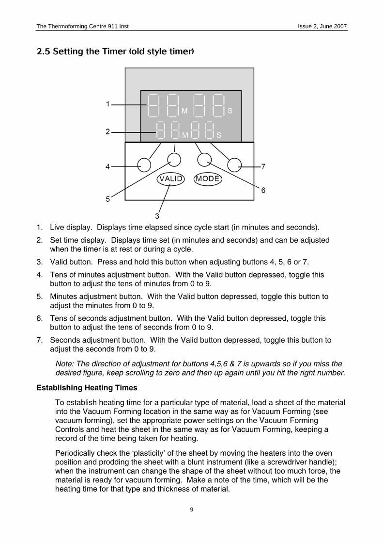
2.5 Setting the Timer (old style timer)
1. Live display. Displays time elapsed since cycle start (in minutes and seconds).
2. Set time display. Displays time set (in minutes and seconds) and can be adjusted when the timer is at rest or during a cycle.
3. Valid button. Press and hold this button when adjusting buttons 4, 5, 6 or 7.
4. Tens of minutes adjustment button. With the Valid button depressed, toggle this button to adjust the tens of minutes from 0 to 9.
5. Minutes adjustment button. With the Valid button depressed, toggle this button to adjust the minutes from 0 to 9.
6. Tens of seconds adjustment button. With the Valid button depressed, toggle this button to adjust the tens of seconds from 0 to 9.
7. Seconds adjustment button. With the Valid button depressed, toggle this button to adjust the seconds from 0 to 9.
Note: The direction of adjustment for buttons 4,5,6 & 7 is upwards so if you miss the desired figure, keep scrolling to zero and then up again until you hit the right number.
Establishing Heating Times
To establish heating time for a particular type of material, load a sheet of the material into the Vacuum Forming location in the same way as for Vacuum Forming (see vacuum forming), set the appropriate power settings on the Vacuum Forming Controls and heat the sheet in the same way as for Vacuum Forming, keeping a record of the time being taken for heating.
Periodically check the ‘plasticity’ of the sheet by moving the heaters into the oven position and prodding the sheet with a blunt instrument (like a screwdriver handle); when the instrument can change the shape of the sheet without too much force, the material is ready for vacuum forming. Make a note of the time, which will be the heating time for that type and thickness of material.

The Thermoforming Centre 911 Inst Issue 2, June 2007
10
2.6 Setting the Timer (new style timer)
1. Live display. Displays time elapsed since cycle start (in seconds). Red Illuminated
display.
2. Set time display. Displays time set (in seconds) and can be adjusted when the timer is at rest or during a cycle. Orange illuminated display.
3. Reset button. Cancels timing cycle.
4. Lock button. Locks the Set Time, so that it cannot be adjusted by pressing toggle buttons 5,6,7 or 8. Press to lock and to unlock.
5. Tenths of seconds toggle button. Press on the down arrow to decrease tenths of seconds and the upward arrow to increase tenths of seconds (between 0 & 9).
6. Seconds toggle button. Press on the down arrow to decrease seconds and the upward arrow to increase seconds (between 0 & 9).
7. Tens of seconds toggle button. Press on the down arrow to decrease tens of seconds and the upward arrow to increase tens of seconds (between 0 & 9).
8. Hundreds of seconds toggle button. Press on the down arrow to decrease hundreds of seconds and the upward arrow to increase hundreds of seconds (between 0 & 9).
9. Operational indicator. Illuminated orange, flashes during cycle.
10. Secondary operational indicator. Illuminated red, flashes during cycle.
11. Format indicator. Illuminated orange, displays the time format (normally seconds).
The Thermoforming Centre 911 Inst Issue 2, June 2007
11
3. Vacuum Forming
Overview
What is Vacuum Forming?
Vacuum Forming produces a forming of a mould in thermoplastic sheet, by firstly heating the material to its plastic condition, pushing a mould into the hot sheet and then evacuating the air from between the mould and the sheet, thus enabling atmospheric pressure to press the sheet onto the mould, forming an accurate replica.
Suitable thermoplastics for vacuum forming are:
• Polystyrene
• PVC
• Polypropylene and
• Polyethylene
Other thermoplastics can be vacuum formed if they are pre-dried (see pre-drying in the technical notes):
• Extruded acrylic
• ABS and
• Polycarbonate
You should decide which thermoplastic you want to vacuum form, verify that the material you have is the material you want (see identifying thermoplastics in the technical notes) and, if required, make sure it is pre-dried.
Moulds can be made from wood, composite boards, metal, ceramic, thermoset plastics - any material that produces the shape required and can withstand the heat of vacuum forming. They must be fixed to a board and where necessary, have evacuation holes to prevent air pockets (see mould making in the technical notes).
Configure the Thermoforming Centre for Vacuum Forming
Turn the Thermoforming Centre on at the Mains Power Switch, select Vacuum Forming at the Mode Selector Switch on the Oven/Vacuum Forming Control Panel and set the Vacuum Forming Controls to full power for both zones (remember that the heaters will take 10-15 minutes to reach full operating temperature).
Ensure there is nothing in the Vacuum Forming, Dome Blowing & Dip Coating Location and that the Platen Elevating Handle is in the vertical position (platen down).
There are two vacuum forming aperture plates (11 x 11” & 11 x 5”). If you are using the 11 x 11 plate, slide it into the location so that the plate lip is at the front and facing down, with the clamp frame handles on the top and at the front. If you are using the 11 x 5 plate, place the stainless steel reducing frame on the platen with the opening running from side to side, then slide the plate into the location in the same way as the larger plate.

The Thermoforming Centre 911 Inst Issue 2, June 2007
12
Vacuum Forming
Place the mould on the platen (inside the reducing frame if using the 11 x 5 plate).
Raise the clamp frame on the Vacuum Forming Plate, place a thermoplastic sheet over the aperture so that it covers the silicone seal, lower the clamp frame and clamp it with the toggle clamp to secure the sheet (check the toggle clamp adjustment - it will vary for different thicknesses of sheet).
Set the Timer (If you do not know the heating time for your material, it needs to be established by the method outlined in Setting the Timer).
Move the Heater from the Oven position to the Vacuum Forming Plate by pulling on the red handle on the front of the Heater.
Start the Timer.
When the timing cycle is complete, cancel it and start the vacuum pump by turning the PSS to ‘Vacuum Forming’.
Move the heater back into the Oven position and raise the platen by pulling the Platen Elevating Handle forwards and down into a horizontal position (where it will lock into place). Note: Do not try and raise the platen whilst the heater is still over the Vacuum Forming location as the mould can damage the heater.
The shape of the mould should now be adopted by the sheet as the air is evacuated from the platen.
Once the platen is fully evacuated and the material has begun to cool (10 to 30 seconds depending on material type and thickness) turn the PSS to ‘Vacuum Forming Blow’ to start releasing the forming from the mould. You must then alternate the vacuum pump by switching between ‘Vacuum Forming Vacuum’ and ‘Vacuum Forming Blow’ until the forming is cool enough to be removed from the clamp frame. This bit requires technique and practice - you have to know:
• When the forming is cool enough to be removed from the clamp frame ie. it is rigid.
• When the forming is free of the mould ie. when you can stop blowing and return to vacuum or, ultimately, when you can stop the process altogether and remove the forming from the clamp frame.
• When to stop blowing and return to vacuum mode without stressing the material too much ie. the blowing function should aim to lift the forming from the mould by just a few millimetres - any more and stress will be produced forming weak spots - particularly at corners.
When the forming is rigid and free of the mould, turn the PSS to ‘Off’, undo the clamp frame toggle clamp, raise the clamp frame and lift the forming from the mould. If it doesn’t lift off easily, secure the clamp frame again and resume the ‘Vacuum Forming Blow’ mode again for a few more seconds.
Once the forming has been released from the mould, lower the platen.

The Thermoforming Centre 911 Inst Issue 2, June 2007
13
4. Dome Blowing
Overview
What is Dome Blowing?
Dome Blowing produces a dome by blowing air into a heated thermoplastic sheet clamped in a circle. The process works because the sheet’s elasticity (see technical notes) offers the same resistance to the air pressure at each point on it’s surface.
Why is a Dome Formed?
The process uses the principle of levers - the clamp ring is the fulcrum, the air pressure is the mass and the distance from the clamp ring provides the moment which produces the force.
The diagram shows that the vertical force acting on the sheet increases the further away from the clamp ring it is applied (or the closer to the centre of the dome). So the centre of the dome will travel the furthest and the edges will not travel at all.
But why a dome and not a pyramid as the Plot of Vertical Forces indicates? Well, there are a number of other forces at work on the material during dome blowing. Because air is fluid, it doesn’t just act vertically, it acts in all directions between horizontal and vertical. There is a cumulative leverage effect - the forces acting on the middle of the sheet will also be making a diminishing contribution to the movement of parts of the sheet closer to the clamp ring. And the material itself has to stretch more the nearer to the centre it is; as it stretches it gets thinner, making it less resistant to the forces acting upon it.
The Thermoforming Centre 911 Inst Issue 2, June 2007
14
If symmetrical domes are to be blown, it is critical that the thermoplastic offers consistent resistance over its surface whilst at thermoforming temperature.
Suitable thermoplastics for dome blowing are:
• Cast Acrylic
• PVC
You should decide which thermoplastic you want to dome blow and verify that the material you have is the material you want (see identifying thermoplastics in the technical notes).
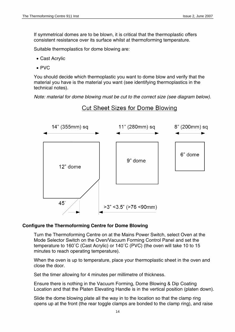
Note: material for dome blowing must be cut to the correct size (see diagram below).
Configure the Thermoforming Centre for Dome Blowing
Turn the Thermoforming Centre on at the Mains Power Switch, select Oven at the Mode Selector Switch on the Oven/Vacuum Forming Control Panel and set the temperature to 160˚C (Cast Acrylic) or 140˚C (PVC) (the oven will take 10 to 15 minutes to reach operating temperature).
When the oven is up to temperature, place your thermoplastic sheet in the oven and close the door.
Set the timer allowing for 4 minutes per millimetre of thickness.
Ensure there is nothing in the Vacuum Forming, Dome Blowing & Dip Coating Location and that the Platen Elevating Handle is in the vertical position (platen down).
Slide the dome blowing plate all the way in to the location so that the clamp ring opens up at the front (the rear toggle clamps are bonded to the clamp ring), and raise

The Thermoforming Centre 911 Inst Issue 2, June 2007
15
the platen to connect the air supply by pulling the Platen Elevating Handle down and forward until it locks in the horizontal position.
Decide which size of dome you are going to make and fit the appropriate clamp ring.
• The 12” clamp ring is fitted to the plate and requires no other attachments.
• The 9” clamp ring is bolted to the 12” ring using the 4 handwheel bolts.
• The 6” clamp ring is bolted to the 12” ring using the 4 handwheel bolts.
Adjust the toggle clamps for your sheet thickness (see diagram below).
• For this you will need some material that is 2 mm thinner than the sheet you are going to form eg. if you are forming a 6mm sheet, set the toggles with a 4mm piece of material or, if you are forming a 3mm sheet, set the toggles with a 1mm piece of material.
• The aim is to adjust the toggles so that, each clamp can be gently locked into place over the sheet of thinner material. When it comes to clamping the actual sheet, this locking action will then be quite firm and provide adequate clamping pressure.
• The pressure is adjusted by changing the length of Clamping stud below the Toggle arm. The more stud that is below the arm the greater the pressure on the sheet. Set this distance by adjusting the height setting nut and securing with the locknut.

The Thermoforming Centre 911 Inst Issue 2, June 2007
16
• Set the height gauge (see diagram below). The Gauge Post screws in to the spare threaded hole in the clamp ring. Wind it in securely and lock with the locknut. Slide the Gauge Arm onto the post and tighten the hand wheel at the required height. Note the maximum height is the radius of the dome - any higher than that and the dome will be wider than the diameter of the clamp ring and impossible to remove without destroying or reheating.
Dome Blowing
Once the sheet has reached its thermoforming temperature:
• Make sure the Dome Blowing Clamp Ring is open (tilted up and to the back of the machine so that there is room to put the heated sheet in) and the correct Clamp ring is securely in position.
• Wearing the Heat Proof Gloves, open the oven and remove the sheet. At this point you will be able to tell if the sheet has reached its thermoforming temperature. If it is not floppy, like a rubber sheet, it is not ready for Dome Blowing and you will have to return it to the oven for a few more minutes.
• When the sheet is ready, take it out of the oven and quickly place it at the centre of the Dome Blowing Plate.
• Lower the Clamp Ring and lock the Toggle Clamps. The easiest way to do this is to pull the back clamp whilst pushing the corresponding front clamp (ie. pull and push both the left hand clamps and then both the right hand clamps).
• As soon as all the Toggles are locked, select Dip Coating Dome Blowing Blow with the PSS. The sheet will begin to form a dome.
The Thermoforming Centre 911 Inst Issue 2, June 2007
17
• Turn the PSS to Dome Blow Hold when the dome is about quarter of an inch from the Height Gauge - during holding, the air inside the dome will be heated by the sheet, thus expanding it and increasing the size of the dome to the full height required.
• If the dome shows any signs of collapse while it is in the holding position, select Dip Coating Dome Blowing Blow again to ‘reinflate’ it.
• When the dome has cooled sufficiently to be rigid again, select the off position with the PSS, undo the toggles, swing the clamping ring up and back and remove the dome. Remember that the thicker the material, the longer the cooling time.
Note: Do not worry if you inadvertently select Dip Coating Dome Blowing Blow once the material has cooled to rigid, it won’t damage the equipment or the dome. It will lift the clamp ring slightly and air will be heard escaping - If this happens, you know the material has cooled sufficiently to be released from the clamp ring.
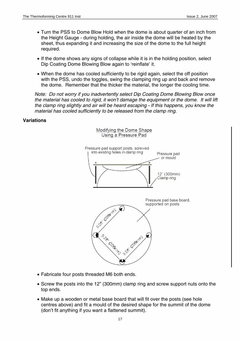
Variations
• Fabricate four posts threaded M6 both ends.
• Screw the posts into the 12” (300mm) clamp ring and screw support nuts onto the top ends.
• Make up a wooden or metal base board that will fit over the posts (see hole centres above) and fit a mould of the desired shape for the summit of the dome (don’t fit anything if you want a flattened summit).

The Thermoforming Centre 911 Inst Issue 2, June 2007
18
• Securely fit to the posts and dome blow in the normal way.
Note: The 12” (300mm) clamp ring is the easiest ring for this variation, if using the smaller rings, the posts have to clamp the ring as well as support the pressure pad.
• Fabricate a wooden mask:
• With Restraining lugs so that it can be secured to the 12” (300mm) Clamp ring by the handwheels normally used to secure the smaller Clamp rings.
• 0.75” (19mm) deep so that the Restraining lugs can be screwed directly on top.
• In one or more sections (no more than four).
• Secure the mask to the 12” (300mm) Clamp ring and dome blow in the normal way.
Note: The 12” (300mm) clamp ring is the easiest ring for this variation, if using the smaller rings, new handwheels would have to be fabricated to clamp the ring and the mask, and the mask would need to be deeper so that it would fit over the smaller ring.

The Thermoforming Centre 911 Inst Issue 2, June 2007
19
• Fabricate a steel mask with Restraining lugs so that it can be secured to the 12” (300mm) Clamp ring by the handwheels normally used to secure the smaller Clamp rings.
• Secure the mask to the 12” (300mm) Clamp ring and dome blow in the normal way.
Note: The 12” (300mm) clamp ring is the easiest ring for this variation, if using the smaller rings, new handwheels would have to be fabricated to clamp the ring and the mask, and the mask would need to be deeper so that it would fit over the smaller ring.

The Thermoforming Centre 911 Inst Issue 2, June 2007
20
• Fabricate an open ended cylinder from thin gauge sheet metal or other suitable material (making sure that the internal face is smooth), with an outside diameter equal to the internal diameter of one of the Clamp rings (any of the three can be used for this exercise).
• Heat and clamp a sheet in the normal way, but before selecting Dip Coating Dome Blowing Blow with the PSS, place the cylinder inside the Clamp ring and hold it there using the handle.
• When Dip Coating Dome Blowing Blow is selected, the thermoplastic sheet will form an elongated, tall dome inside the cylinder.
Note: A tall dome will suffer more thinning at its summit than a hemisphere - PVC may be more suitable than Cast Acrylic.

The Thermoforming Centre 911 Inst Issue 2, June 2007
21
5. Plastic Dip Coating
Overview
What is Plastic Dip Coating?
Plastic Dip Coating covers all or part of a metal object with a smooth, even coat of thermoplastic, by heating and then immersing it in a bath of fluidised thermoplastic powder.
The thermoplastic powder is fluidised by high volume, low pressure air, whilst the metal part is heated in the oven.
Suitable thermoplastics for plastic dip coating are:
• Nylon
• Polyethylene
• Polypropylene
You should decide which thermoplastic you want to use for dip coating, and verify that the material you have is the material you want. Identifying thermoplastics for dip coating is difficult because, obviously, they are powders, not sheets that can be burnt, stressed or solvent tested. So it is important to know what you have in your workshop and make sure it is labelled correctly and doesn’t get mixed up. It is also important that powders are kept in a dry place because damp powders will not fluidise very well.
The Thermoforming Centre comes with yellow nylon powder and blue polyethylene powder - both in clearly labelled white plastic containers.
When a hot metal part is immersed in the bath of fluidised thermoplastic, the granules close to the surface of the part are heated (by the metal part) to their melting or fusing temperature. At this temperature they fuse with each other and stick to the metal surface, forming the coating. The longer the metal is immersed in the fluidised bath, the more granules will fuse and the thicker the coating will be.
When the part is removed from the fluidised bath it will have a fuzzy appearance because the granules on the outside have not yet had a chance to heat up completely. During the 20 - 40 seconds immediately after the part has been removed from the bath, heat continues to be given off and the thermoplastic continues to fuse and flow until the surface is smooth.
Sometimes a part is not hot enough, or there is too much thermoplastic on the part due to being dipped for too long and the surface does not run smooth; it has an orange peel texture. If this happens a process called Post Heating must be carried out, where the coated part is suspended in an oven and heated to the fusing temperature of the thermoplastic coating.
The temperature that a part has to be heated to depends on the thermoplastic coating and the thermal mass of the part. The less thermal mass a part has, the

The Thermoforming Centre 911 Inst Issue 2, June 2007
22
quicker it will lose its heat and the hotter it will need to be. A guide to temperatures is below.
Configure the Thermoforming Centre for Plastic Dip Coating
Turn the Thermoforming Centre on at the Mains Power Switch, select Oven at the Mode Selector Switch on the Oven/Vacuum Forming Control Panel and set the temperature according to the part that you are going to dip coat (see the chart above for guidance and remember that the oven will take some time to reach operating temperature).
When the oven is up to temperature, place the object to be coated in the oven and set the timer, remembering that the bigger the part, the more heating time it will need. Light gauge materials will only need 10 minutes in the oven but, heavier parts could take up to an hour. The heating times for your piece need to be established by experiment.
Ensure there is nothing in the Vacuum Forming, Dome Blowing & Dip Coating Location and that the Platen Elevating Handle is in the vertical position (platen down).
Slide the 11 x 11” Vacuum Forming Plate into the location so that the plate lip is at the front and facing down, with the clamp frame handles on the top and at the front (the same as for Vacuum Forming).
Raise the clamp frame and put the Dip Coating Tank into the forming aperture so that the Vacuum Forming Plate’s silicon seal is covered by the tank’s metal skirt. Clamp in position, as if it were a thermoplastic sheet.

The Thermoforming Centre 911 Inst Issue 2, June 2007
23
Fill the tank with the required thermoplastic powder (unless there is already powder in the bath) to within 3” (75mm) of the top of the bath.
Fully open the air bleed screw at the front of the dip coating unit. This valve controls the amount of air going to the Dip Coating Tank. When it is fully open (anti clockwise) no air will be fed to the tank and the plastic powder will not fluidise. Fully opening the valve prevents the powder being blown out of the tank on start up.
Select Dip Coating Dome Blowing Blow with the PSS.
Slowly turn the air bleed valve clockwise, until the powder is fluidised enough for dip coating (test the fluidisation with a long cold object, such as a spanner; if you can touch the bottom of the tank without meeting resistance, the powder is fluidised enough for dip coating). The powder level will rise by 10 - 20% when it is fluidised.
Dip Coating
Wearing the heat proof gloves and using an appropriate tool, (pliers, grips or a double sided hook if you intend to hang the coated product for cooling or Post Heating) take the heated metal part out of the oven.
Immerse it either wholly or partially in the fluidised bath for 5 - 6 seconds (the longer the piece is immersed the thicker the coating will be).
Lift the coated part out of the bath and allow the material to fuse and flow to a smooth finish for 20 - 40 seconds.
Once the surface is smooth either;
• suspend from a suitable point where the piece can cool undisturbed, or

The Thermoforming Centre 911 Inst Issue 2, June 2007
24
• immerse in cold water to rapidly cool the piece (useful if you are holding the part with a pair of pliers or grips and cannot suspend it from anywhere).
If the surface fails to go smooth and you are left with the orange peel texture, reset the oven to the appropriate Post Heating temperature and suspend the piece in there, until the material has fused to a quality finish.
Immersing part of an object in the fluidised bath coats part of it - like the scissor handles in the above picture.

The Thermoforming Centre 911 Inst Issue 2, June 2007
25
6. Injection Moulding Note: You will need an aluminium or epoxy resin mould, built in two or more parts to the following specification with appropriate clamping and releasing bolts (see moulds supplied with the Thermoforming Centre):
Overview
What is Injection Moulding?
Injection moulded parts are formed when a thermoplastic is heated until it is completely plastic or molten, and then forced, under pressure, into a mould and cooled. Injection moulded parts are all around us, everywhere we look, in almost every room, in every building, anywhere in the world. Look at almost any modern object, electrical, furnishing, eating, sporting - anything at all, and you will see injection moulded parts in various thermoplastics.
The size and volume of the industry means that commercial machines are large and employ complex technology, from the mixing and injecting screws to the product manipulation robots (more is said about injection moulding in ????).
The Thermoforming Centre emulates the process by heating the material in the oven and injecting the material using the hydraulic ram.Suitable thermoplastics for injection moulding with the Thermoforming Centre are:
• Material Recommended Oven Temp.
• Polyethylene 195˚C
• Nylon 210˚C
• Polystyrene 195˚C

The Thermoforming Centre 911 Inst Issue 2, June 2007
26
Configure the Thermoforming Centre for Injection Moulding.
Turn the oven shelf upside down so that the holding brackets for the Injection Moulding/Extrusion crucibles are facing upwards.
Turn the Thermoforming Centre on at the Mains Power Switch, select Oven at the Mode Selector Switch on the Oven/Vacuum Forming Control Panel and set the temperature to 195˚C (remember that it will take some time to reach operating temperature).
When the oven is up to temperature, fill the Injection Moulding crucible (the one with the nozzle that locates in the top of the injection mould) with the required thermoplastic powder and place it in the oven along with the mould or moulds to be injection moulded. One crucible of thermoplastic injection moulds both of the moulds that come with the 911 (the square box and the wheel).
Set the timer for 20 minutes.
Injection Moulding
At the end of the timing cycle, put on the heat proof gloves, take the mould out of the oven and put it on the PTFE plate behind the clear door below the Pneumatic power cylinder, making sure that it is sitting flat, in the recess designed for it.
Using the Crucible handle, remove the crucible from the oven and slot it into the support bracket below the pneumatic ram. Make sure that the crucible lugs are in the lower part of the slot, that the crucible nozzle is sitting in the mould’s docking cone and that the mouth of the crucible lines up with the pneumatic ram. Note: polyethylene and polystyrene will appear to have shrunk as air has been purged during heating, nylon will have shrunk too, but a skin may have formed at the top making it appear to have the same (or greater) volume.
Close the pressing bay door. Note: the Ram Up/Down toggle will not work unless the cabinet door is closed.

The Thermoforming Centre 911 Inst Issue 2, June 2007
27
Select Extrusion/Injection Moulding with the PSS and then select Ram Down with the Ram Up/Down toggle switch. If the crucible is only half full, or your mould is not very high (eg. if you aren’t using a standard C.R.Clarke blank) you may want to push the Rapid Approach button at this point. The ram will move down and continue to move as it pushes the material through the crucible.
Once the Pneumatic Ram has stopped moving, or when you see thermoplastic oozing out of the air evacuation holes, you know that the moulding process is complete and you can select Ram Up with the Ram Up/Down toggle switch.
Note: it is better to do this later rather than sooner - it is impossible to top up an injection mould once it is finished and running the machine for a longer time doesn’t do any harm.
Once the Ram is in the Up position, select Off with the PSS.
Open the door and using the Crucible handle, take the crucible out of the support bracket below the pneumatic ram and place it in the support bracket to the right of the pressing bay to cool, or back in the oven if you intend to do further injection moulds.
Still wearing the gloves, take the mould out of the unit and cool it by running cold water over it for at least 2 minutes.
Once it is cool, remove the four bolts clamping the two halves of the mould together and wind the two ejector bolts down, separating the two halves.
The moulding should remain on the male part of the mould. Remove the excess material from the docking cone (a counter-sink tool works best for this but, be careful to avoid cutting into the docking cone itself) and, supporting the mould on a bench or vise, prize the moulding from the mould using a thin flat blade (such as the plastic cutting knife supplied with the Thermoforming Centre). Take care not to break the mould when prizing the moulding from the mould, - if it is square prize it at the corners, which are stronger.
The finished injection mould has a rod of material sticking up from its middle or wherever the injection point for the mould was. This can be left there if it isn’t in the way, or removed using a small modelling drill or similar tool (don’t try to snap it off because you might break other parts of the mould).
Note: The small protuberance that remains is a feature of every injection moulded part and is a good way of telling whether a part was injection moulded or not.
Purging
Once you have used a crucible for injection moulding, it will always have a residue of thermoplastic material in it. If you have been injection moulding, say, polyethylene and then want to injection mould polystyrene or nylon, you first have to purge polyethylene residue from the crucible.
• Firstly, heat the crucible to the appropriate temperature for the thermoplastic which you are purging.
• Fill the water tube with water.
The Thermoforming Centre 911 Inst Issue 2, June 2007
28
• When the crucible is up to temperature, take it out of the oven using the crucible handle (and wearing the heat proof gloves) and place it in the crucible support bracket below the pneumatic ram with the nozzle through the hole in the PTFE plate.
• Close the door and select Extrusion Injection Moulding with the PSS and Ram Down with the Ram Up/Down toggle.
• Press the Rapid Approach button to bring the ram in contact with the thermoplastic as soon as possible.
• The thermoplastic residue will be ‘extruded’ into the water tube. When the ram has stopped moving and thermoplastic has stopped extruding from the nozzle, select Ram up with the Ram Up/Down toggle and cut the extruded waste from the end of nozzle using the knife and allowing the waste extrudate to fall into the water tube.
• Remove the waste from the water tube by sliding the tube down or removing it completely from its clamps.
• Open the door and, still wearing the gloves, remove the crucible from the support bracket using the crucible handle and quarter fill with the new material.
• Heat and extrude this material in the same way as above.
• You are now ready to injection mould with the new material. Fill with the new material and injection mould as described previously in this section.
Note: Purging is only required when you are changing material. If you are injection moulding using the same material as the residue in the crucible, topping up, without purging, is all that is required.
Cleaning
An alternative to purging, is to remove the nozzle from the end of the crucible (by removing the three bolts that secure it) and cleaning it with the wire brush provided with the Thermoforming Centre. The crucible itself can be cleaned by purging it (as described above) without the nozzle fitted.
The Thermoforming Centre 911 Inst Issue 2, June 2007
29
7. Extrusion
Overview
What is Extrusion?
A thermoplastic is heated until it is completely plastic or molten, and then forced, under pressure, through a die. Flat sheets, rods, bars, sections and tubes are all produced by extrusion.
Almost all sheets are produced by extrusion (with the exception of cast acrylic) and sections for window and door frames, seals, water pipes, rainwater goods, electric cables, etc. (more is said about extrusion in ????).
The Thermoforming Centre emulates the process by heating the material in the oven and extruding the material using the hydraulic ram.
Note: Most commercial extrusion is done horizontally. For practical reasons of scale and space, the Thermoforming Centre extrudes vertically.
Suitable thermoplastics for extruding with the Thermoforming Centre are:
• Material Recommended Oven Temp.
• Polystyrene 195˚C
Configure the Thermoforming Centre for Extrusion.
Turn the oven shelf upside down so that the holding brackets for the Injection Moulding/Extrusion crucibles are facing upwards.
Turn the Thermoforming Centre on at the Mains Power Switch, select Oven at the Mode Selector Switch on the Oven/Vacuum Forming Control Panel and set the temperature to 195˚C (remember that it will take some time to reach operating temperature).
When the oven is up to temperature, fill the Extrusion crucible (the one with the ‘H” shaped die on one end) with the polystyrene granules and place it in the oven. One crucible of polystyrene extrudes about 2 lengths of ‘I’ beam.
Set the timer for 20 minutes.
Fill the water tube almost to the top with water (leaving room for displacement by the extrusion) and snap it into its spring clamps, about 0.5 - 3.0” (12 - 75mm) from the underside of the pressing bay.
Close the Ram speed controller and then open it half a turn (anti-clockwise) to slow the speed of extrusion. If faster extrusion is required, it can be opened up more later.
Extrusion
At the end of the timing cycle, put on the heat proof gloves and, using the Crucible handle, remove the crucible from the oven and slot it into the support bracket below the pneumatic ram. Make sure that the crucible lugs are in the lower part of the slot, that it is sitting flat, in the recess designed for it and that the mouth of the crucible

The Thermoforming Centre 911 Inst Issue 2, June 2007
30
lines up with the pneumatic ram. Note: the polystyrene will appear to have shrunk as air has been purged during heating.
Close the pressing bay door. Note: the Ram Up/Down toggle will not work unless the cabinet door is closed.
Select Extrusion/Injection Moulding with the PSS and then select Ram Down with the Ram Up/Down toggle switch. If the crucible is only half full, you may want to push the Rapid Approach button at this point. The ram will move down and continue to move as it pushes the material through the crucible.
Polystyrene will start to extrude from the die into the water tube. Allow the extrusion to continue until you have the length of extrusion you need or until it is reaching the bottom of the water tube. Then select Ram up with the Ram Up/Down toggle switch.
Once the Ram is in the Up position, select Off with the PSS.
Cut the extrusion away from the die using the knife and allow to fall into the water tube (you may need to lower the water tube a little to do this).
Remove the extrusion from the water tube by moving the tube down or taking it out of its spring clamps completely.
Return the water tube to its extrusion position and perform further extrusions if required.
Open the door and, using the Crucible handle, take the crucible out of the support bracket below the pneumatic ram and place it in the support bracket to the right of the pressing bay to cool, or refill and place back in the oven if you intend to do further extrusions.

The Thermoforming Centre 911 Inst Issue 2, June 2007
31
Observations
The extruded section can be heat bent, glued and solvent cemented.
The phenomenon of ‘Die Swell’ should be noted, ie; the die sections have a thickness of only 0.015” (0.38mm) but, the extruded sections are much thicker than that, the thickest being 0.08” (2.00mm). The overall height of the ‘I’ die is 0.315” (8mm) compared to the extruded ‘I’ height being 0.472” (12mm). This expansion is caused by the molecular chains, which have been artificially aligned at the point of extrusion, reorganising themselves into a random alignment, a bit like hair underneath a hat bouncing back up when the hat is taken off. This phenomenon has to be taken into account when designing extrusion dies.

The Thermoforming Centre 911 Inst Issue 2, June 2007
32
8. Welding
Overview
What is Welding?
The joining together of two pieces of material, through the fusion of a third piece such as a filler or rod. Hot air, ultrasonic, vibration, spin and hot plate technologies have all been developed for thermoplastics. Like metal welding, the two pieces being welded have to be the same material, as does any filler (so that everything ‘melts’ at the same temperature).
The Thermoforming Centre offers Hot Air welding, which is suitable for:
• Polypropylene
• PVC
• ABS
Configure the Thermoforming Centre for Welding.
Caution: The metal components of the welding torch will become hot during use!
Lift the folding work table and latch it in the horizontal position.

The Thermoforming Centre 911 Inst Issue 2, June 2007
33
Set the table angle stop to the required angle Note: if you are welding angles greater or lesser than 90˚ it is advisable to machine the angle onto one of the edges.
Set the welding torch temperature to 7 or 8, make sure that the tacking shoe is down over the welding nozzle and place it in the holster in the work table.
Note: the tacking and welding temperatures suggested are guides only; the hotter the temperature, the faster the welding process, but the greater the danger of spoiling the material. The best temperature for your operation has to be decided by experimentation.
Turn the Thermoforming Centre on at the Mains Power Switch and select Welding with the PSS
Welding
Place one piece of thermoplastic sheet flat on the table with the other resting against the angle stop, joining the first piece in the correct place (you might want to position the assembly at one end of the table to prevent it moving during welding).
Wearing the heat proof gloves and holding the upright piece in place with one hand, take the welding torch out of the holster and move the tacking shoe along the joint

The Thermoforming Centre 911 Inst Issue 2, June 2007
34
applying gentle pressure as you do so. You should see the two pieces of material soften and merge at the joint. Turn the assembly around and repeat on the other side.
Flick the tacking shoe back using an edge of the work table - protected by a piece of scrap thermoplastic or wood - and reduce the torch temperature to 5 or 6.
With the assembly in position, take a piece of welding rod (remembering that it has to be the same material as you are welding) feed it into the end of the torch so that a length is sticking out of the nozzle, and then drag the torch across the joint once again - pushing the welding rod into the joint with the nozzle as you go. It is important to judge the speed correctly. When you have got it right, you will find that the welding rod feeds itself through the torch.
The Thermoforming Centre 911 Inst Issue 2, June 2007
35
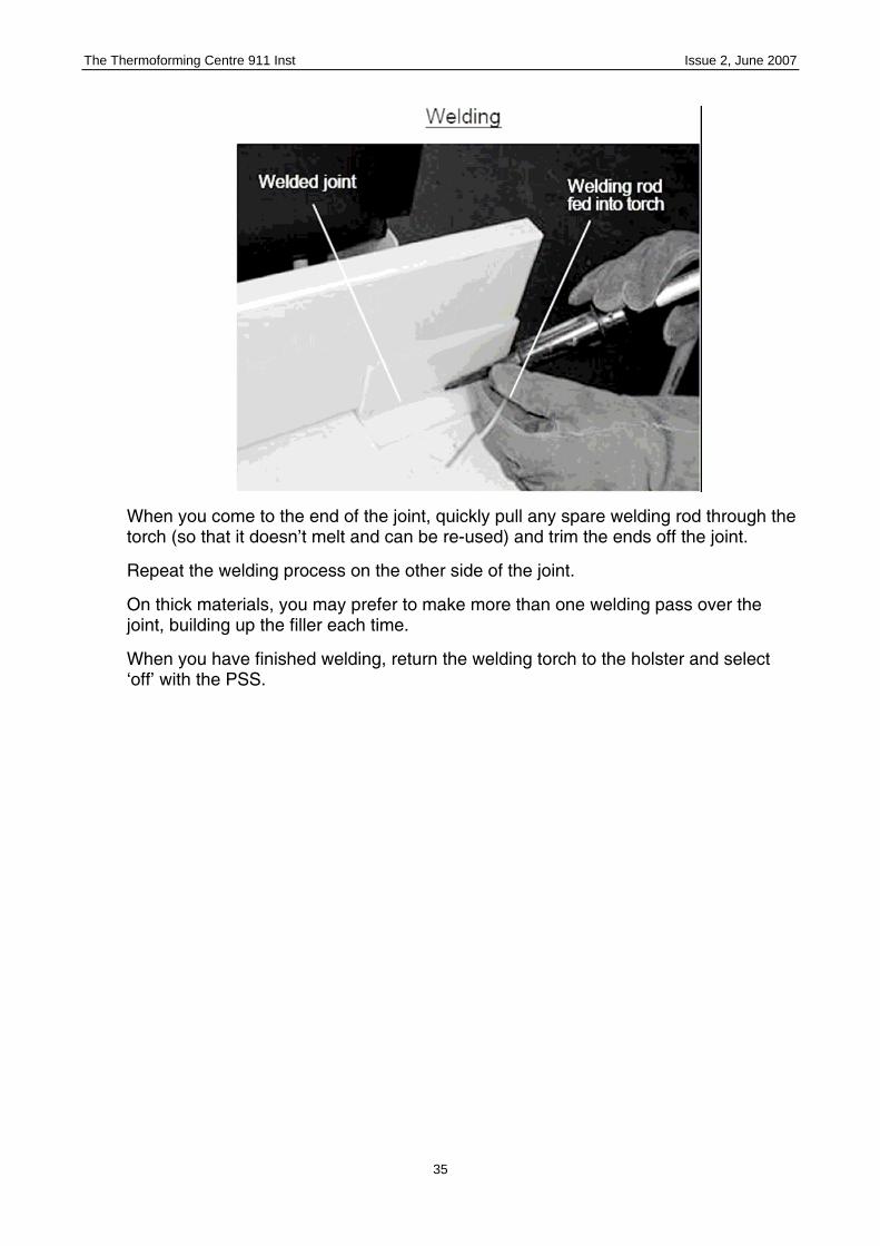
When you come to the end of the joint, quickly pull any spare welding rod through the torch (so that it doesn’t melt and can be re-used) and trim the ends off the joint.
Repeat the welding process on the other side of the joint.
On thick materials, you may prefer to make more than one welding pass over the joint, building up the filler each time.
When you have finished welding, return the welding torch to the holster and select ‘off’ with the PSS.

The Thermoforming Centre 911 Inst Issue 2, June 2007
36
9. Press Forming
Overview
What is Press Forming?
A thermoplastic sheet is heated and moulded in a two part mould which is pressed together under pressure.
Suitable thermoplastics for press forming with the Thermoforming Centre are:
• Material Recommended Oven Temp.
• Cast Acrylic 165˚C
• ABS 120˚C
• PVC 130˚C
Producing a Press Forming Mould
The Press Forming mould can be made from wood, composite board, aluminium or epoxy resin and must fit the above specifications.
Configure the Thermoforming Centre for Press Forming.

The Thermoforming Centre 911 Inst Issue 2, June 2007
37
Turn the Thermoforming Centre on at the Mains Power Switch, select Oven at the Mode Selector Switch on the Oven/Vacuum Forming Control Panel and set the temperature according to which material you are going to press form. Remember that the oven will take some time to reach operating temperature.
Remove the crucible support bracket from the pressing bay, by undoing the two wing nuts at the back.
Replace the PTFE plunger with the circular aluminium pressure plate.
Place your mould in the pressing bay.
When the oven is up to temperature, place your material (cut so that it fits inside the mould) inside the oven on the shelf. If the material has a protective covering, this should be removed.
Work out the heating time for your material, or establish it by experiment, and set the timer accordingly.
Press Forming
When the material is ready, select Extrusion/Injection Moulding with the PSS.
Wearing the gloves, take the material out of the oven and place it in the mould.
Close the pressing bay door. Note: the Ram Up/Down toggle will not work unless the bay door is closed.
Select Ram down with the Ram Up/Down toggle switch and press the Rapid Approach button until the ram reaches the mould.

The Thermoforming Centre 911 Inst Issue 2, June 2007
38

The Thermoforming Centre 911 Inst Issue 2, June 2007
39
The ram will press the mould together, moulding the plastic as it does so. Wait for 2 or more minutes (depending what thickness you are moulding and remembering that thicker materials will take longer to cool) before selecting Ram up with the Ram Up/Down toggle and releasing the moulding from the mould.


