operated device estimation framework-final...
TRANSCRIPT
OPERATED DEVICE ESTIMATION FRAMEWORK
A Thesis
by
JANARTHANAN RENGARAJAN
Submitted to the Office of Graduate Studies of
Texas A&M University
in partial fulfillment of the requirements for the degree of
MASTER OF SCIENCE
December 2008
Major Subject: Computer Engineering

OPERATED DEVICE ESTIMATION FRAMEWORK
A Thesis
by
JANARTHANAN RENGARAJAN
Submitted to the Office of Graduate Studies of
Texas A&M University
in partial fulfillment of the requirements for the degree of
MASTER OF SCIENCE
Approved by:
Co-Chairs of Committee, Billy Don Russell, Jr.
Narasimha Reddy
Committee Members, Donald K. Friesen
Head of Department, Costas N. Georghiades
December 2008
Major Subject: Computer Engineering
iii
ABSTRACT
Operated Device Estimation Framework. (December 2008)
Janarthanan Rengarajan, B.E., Peelamedu Samanaidu Govind College of Technology
Co-Chairs of Advisory Committee: Dr. Billy Don Russell, Jr.
Dr. Narasimha Reddy
Protective device estimation is a challenging task because there are numerous
protective devices present in a typical distribution system. Among various protective
devices, auto-reclosers and fuses are the main overcurrent protection on distribution
systems. Operation of a protective device in response to a particular fault condition
depends upon the protective device’s operating behavior and coordination of various
such protective devices.
This thesis presents the design and implementation of a protective device
estimation algorithm which helps in identifying which protective devices have operated
to clear a short circuit condition. The algorithm uses manufacturer’s device details,
power quality data measured from substation monitoring devices and power system
event features estimated using existing DFA algorithms. The proposed technique can be
used to evaluate coordination of these protective devices and helps in locating a fault in a
distribution system feeder. This approach is independent of feeder topology and could be
readily used for any distribution system. The effectiveness of this algorithm is verified
by simulated and actual test data. Suggestions are included for future research and
application by electric utilities.

iv
To my family and friends

v
ACKNOWLEDGEMENTS
I wish to express my profound gratitude to my advisor Dr. B. Don Russell for the
support and encouragement that made this thesis possible. I am grateful to him for
having provided me an opportunity to work as a research assistant on this project.
Thanks to him for the entire efforts he has put into to provide me assistantship
throughout my course of study.
I cannot forget to thank Carl L. Benner whose expertise and suggestions were
invaluable to the progress that I made with this work. I wish to thank Karthick
Manivannan for his constant support. I also wish to thank all the graduate research
assistants (2006-2008) of the Power System Automation Laboratory of the Electrical
Engineering Department at Texas A&M University. I wish to acknowledge the Electric
Power Research Institute (EPRI) for their funding and support of this project.
I thank my graduate committee members, Dr. Narasimha Reddy and Dr. Donald
K. Friesen, for their willingness to serve on my committee.
Finally, I thank my family and friends for their loving support and words of
encouragement.
vi
NOMENCLATURE
A Amperes
AI Artificial Intelligence
C Cooling factor
Ck Cooling factor for kth
reclosing time interval
CB Circuit Breaker
DFA Distribution Fault Anticipator
EPRI Electric Power Research Institute
F Fast
I Current
Idevice Magnitude of fault current seen by protective device
Iin Input current
Iout Output current
kA Kilo-Ampere
MM Minimum Melt
OC Overcurrent
P Reduction in melting time of fuse due to preloading effect
PSAL Power System Automation Laboratory
PQ Power Quality
S Slow
SCADA Supervisory Control And Data Acquisition

vii
SQL Structured Query Language
t Time
tdevice Duration for which fault current is seen by the protective device
tfuse-clear Estimated clearing time of fuse
tfuse-melt Estimated melting time of fuse
trecloser-fast Estimated matching time on recloser fast curve
trecloser-delayed Estimated matching time on recloser slow curve
Tl Point on the maximum equivalent lockout curve of recloser
TRj Maximum clearing time at the chosen current for the jth
operation
TC Total Clearing
TCC Time Current Characteristic
V Volts / Voltage
viii
TABLE OF CONTENTS
Page
ABSTRACT .............................................................................................................. iii
DEDICATION .......................................................................................................... iv
ACKNOWLEDGEMENTS ...................................................................................... v
NOMENCLATURE.................................................................................................. vi
TABLE OF CONTENTS .......................................................................................... viii
LIST OF FIGURES................................................................................................... x
LIST OF TABLES .................................................................................................... xi
CHAPTER
I INTRODUCTION................................................................................ 1
II REVIEW OF PROTECTION DEVICE MONITORING
USING PQ DATA ............................................................................... 4
III BACKGROUND OF PROTECTIVE DEVICES ................................ 9
Fuses............................................................................................... 9
Reclosers ........................................................................................ 10
Circuit breaker / relay combination................................................ 11
Sectionalizers ................................................................................. 11
Coordination of protective devices ................................................ 11
Influence of temperature in coordination of devices...................... 17
IV PROTECTIVE DEVICE ESTIMATION FRAMEWORK ................. 21
Problem formulation ...................................................................... 21
Protective device estimation approach ........................................... 24
Identification of recloser operations............................................... 29
Identification of fuse operations..................................................... 31
ix
CHAPTER Page
V SOFTWARE IMPLEMENTATION.................................................... 33
VI RESULTS AND DISCUSSIONS ........................................................ 38
Case A ............................................................................................ 38
Case B ............................................................................................ 40
Case C ............................................................................................ 42
VII CONCLUSIONS AND FUTURE WORK .......................................... 43
REFERENCES.......................................................................................................... 44
VITA ......................................................................................................................... 49
x
LIST OF FIGURES
Page
Figure 1 Generic structure of protective device .............................................. 9
Figure 2 Fuses protecting reclosers ................................................................. 12
Figure 3 Fuses protecting fuses ....................................................................... 15
Figure 4 Reclosers protecting fuses ................................................................. 15
Figure 5 Reclosers protecting reclosers ........................................................... 16
Figure 6 Heating and cooling of fuse during recloser’s operating sequence... 18
Figure 7 Cooling factors versus time for different fuse links .......................... 19
Figure 8 One-line diagram of a typical distribution system ............................ 22
Figure 9 Typical power system event data capture record .............................. 25
Figure 10 3 Φ voltages and currents during OC fault observed at substation. .. 26
Figure 11 Voltage (a) and current (b) waveform for OC fault .......................... 28
Figure 12 Coordination of downstream fuse with upstream recloser................ 30
Figure 13 Matching fault point to fuse operation .............................................. 31
Figure 14 Class diagram of developed object model......................................... 35
Figure 15 Recloser estimation with 65 T fuse coordination.............................. 39
Figure 16 Fuse estimation.................................................................................. 41
xi
LIST OF TABLES
Page
Table 1 Fuse to fuse coordination table for T type fuses ............................... 14
Table 2 Class with attributes and operations ................................................. 34
Table 3 Symbol definition ............................................................................. 35
Table 4 Device table....................................................................................... 36
Table 5 Curve table ........................................................................................ 36
Table 6 Actual OC fault data captures – Device estimation analysis............. 42

1
CHAPTER I
INTRODUCTION
Electrical power distribution system feeders are susceptible to different kinds of
faults caused by a variety of situations like weather conditions, equipment failures,
disturbances caused by animals, etc. Most of the power distribution feeder systems in
the United States are built over radial methodology. Associated with these distribution
systems, there exist many ancillary systems which assist in meeting the requirements for
safety, reliability and quality of supply. Among them, protection systems are the most
important one. The objective of the protection system is to mitigate the harmful effects
of abnormal events on the components of distribution system. The radial distribution
systems typically have overhead distribution lines which are protected based on the well
known radial philosophy - reclosers on the main feeder and fuses on the lateral feeders.
These conventional protection devices have been proven to be reliable, secure and
dependable as they operate only when there is a fault in the system. Most faults on the
lateral feeders are temporary in nature and therefore require a recloser’s instantaneous
trip operation to de-energize the system and allow the fault to clear prior to any fuse
operation in a typical fuse saving scheme. If the fault fails to clear and becomes
permanent, the fuse will then operate to isolate the faulted section from the network
resulting in loss of power supply for that portion of feeder. Such kinds of power outages
are highly undesirable and utility companies do their utmost to keep the outages
____________
This thesis follows the style of IEEE Transactions on Power Delivery.
2
to minimum possible level by quickly locating the cause of the disturbance and
implements necessary measures to restore service to the end customers. Nevertheless,
these kinds of disturbances and fault conditions are inevitable. This calls for efficient
and intelligent identification of faults and root cause of the fault.
For any fault occurring in this kind of radial distribution systems, we need only a
single interrupting protective device to clear the fault. But in a typical radial distribution
system, there exists many such protective devices and the device that operates to clear a
fault is determined by coordination of these protective devices based on their ratings and
operating behavior. These protective devices include circuit breakers, reclosers, relays,
sectionalizers, and fuses [1]. They appear in series along a feeder in order to sense the
fault current and interrupt the fault. Proper coordination of these protective devices is
impeded because of the differences in protective device time-current characteristic curve
slopes and coordination of multiple devices at a time. Improper coordination of these
devices results in device misoperation resulting in more frequent and longer duration of
voltage disturbances thereby impacting the overall power quality of the system.
Recognition of this kind of device misoperation might be undetectable until a major
event occurs in the system.
As a part of Distribution Fault Anticipator (DFA) project, utility companies are
installing feeder monitoring devices at substations to monitor the power data. Whenever
the monitoring device identifies any current or voltage variation that is outside the preset
threshold, it records all phase current and voltage waveforms. This data is transferred
later to the database server in Power System Automation Laboratory (PSAL) at Texas
3
A&M University. Many algorithms developed by researchers at PSAL, Texas A&M
University, currently analyze these power data using extensive signal processing
methods and generate detailed reports that include classification and identification of
various disturbances. Even though the reports estimate device operations like “breaker
operation”, “recloser operation”, “capacitor switching”, current algorithms do not
quantify and qualify the exact device that operated during the fault conditions. This calls
for the development of an operated device estimation framework.
This thesis describes the work performed to implement automated estimation of
protective devices that operate during fault conditions in a radial distribution system
using the approach described in [22] in combination with modified coordination strategy
as described in [26]. This operated device estimation framework utilizes relevant
information and data available from the distribution system database & records of
electrical quantities from substation monitoring devices, results from existing fault
classification and feature estimation algorithms developed in PSAL, Texas A&M
University and/or simulated data. Chapter II of the thesis briefly reviews previous work
done on the protective device monitoring and estimation methods. Chapter III outlines
the description of protective devices, generic modeling approach and co-ordination
strategy. This is followed by the problem formulation and operated device estimation
framework in Chapter IV. Chapter V presents the software implementation. The results
and case studies are presented in Chapter VI. Concluding remarks and scope for future
work is provided in Chapter VII.
4
CHAPTER II
REVIEW OF PROTECTION DEVICE MONITORING USING PQ DATA
With the development of computers, many artificial intelligence methods such as
expert systems, neural networks, etc., emerged. These methods provide a way to capture
the experience of operators or engineers, and can help people to do much laborious
work. Many artificial intelligence solutions & algorithms have been published about
fault location, disturbance classifications using data from power quality monitoring
devices and estimating the protective device that operated, for example [2] and [3]. The
most primitive of these identification methods is visual inspection by utility personnel
upon receiving trouble calls from the customers, which is time consuming and needs lot
of man power. Most of the algorithms developed use the protective device information
and feeder topology to estimate the accurate device that operated during the fault
conditions and identify the faulted section to locate the fault. These methods mostly
employ artificial intelligence methods to process the data. One such method uses the
topology information updated manually or by Supervisory Control And Data Acquisition
(SCADA) systems and the information gathered from switch activations and protective
device information as inputs to an expert system that estimates the device that operated
and identifies the faulted section [4]. Another method uses an expert system to estimate
the faulted section by using dynamic inference of protective device coordination [5].
Some algorithms have been proposed for systems equipped with SCADA, that use an
expert system and various machine learning techniques to analyze different possible

5
sequence of events caused by differences in operation of protective devices for a fault
diagnosis [6], [7].
Another artificial intelligence technique, fuzzy logic could be used to account for
uncertainties in the input data of distribution system faults. One such method uses feeder
topology for fault diagnosis by employing fuzzy rules [8]. Another method employs
feeder topology information, pre-fault and post-fault system configuration information to
identify the fault islands, and assigns possibilities to different devices in sections [9].
Many other methods that employ fuzzy logic uses information like feeder topology
geographical information, utility personnel’s expertise, short circuit calculations, post-
fault system configurations has also been proposed [10] – [12].
With computer programs that simulate the behavior of human experts in solving
a complex problem, expert systems have received considerable attention for developing
fault location methods. Many researchers used rule-based expert systems based on
topology information and protective device information. Ypsilantis et al. proposed a rule
based expert system that also used the status of protective devices [13]. This method was
different from other methods due to its consideration of sequential information in the
network. Teo developed a rule-based diagnostic system that used feeder topological
information and real time data from SCADA systems [14]. The system used two types of
rules. A set of core rules using breaker trips and bus status was normally enough to cover
a majority of fault conditions. In the cases where the core rules failed, exception rules
were generated by interaction with system operators. These exception rules used breaker
trip information and the islands formed in the faulted network. Rule-based expert

6
systems have a powerful capability to mimic human experience. However, a number of
rules are needed to describe various devices. The tasks of knowledge-acquisition and
maintenance of knowledge base are often laborious and tedious, and the development of
an expert system is often a costly and very lengthy process. Hence, the portability of
expert systems is very important. Instead of representing the operator’s expertise as
complicated rules, Hadjsaid and Bretas presented a special knowledge based system that
captured the post-fault network state, and recorded it as a pattern [15]. When linking to a
distribution network simulator, the diagnostic system was trained. When a new fault
happened, a matching mechanism was used to compare the network state with records to
identify the fault location. If no one matched, the system would consider it as a new fault
condition and prompt the user to enter the faulted element.
Some of the approaches use a neural network for estimation of the device that
operated based on information about the states of different protective devices on the
circuit and phasor measurements at the substation [16], [17]. Neural networks were used
as the knowledge base, instead of heuristic rules. The feeder fault voltage, circuit breaker
status, real power of feeders during the normal condition, and real power of feeders
during short circuit, etc, were used to train the neural network. Yang et al. presented
distributed neural nets diagnosis system constructed by the training database that
associated the protective scheme using the individual sections [17]. By using the
distributed processing technique, the burden of communication between the control
center and substations was alleviated. In order to implement an on-line estimation
system, Bi et al. employed a multi-way graph partitioning method based on weighted
7
minimum degree reordering to partition a large-scale power network into some sub-
networks [18], [19]. Then a radial basis function neural network and its companion fuzzy
system were used to identify the device that operated and isolate the fault section based
on information available from SCADA systems. The speed of this method made it
possible to use it as an on-line system. Glinkowski and Mohammed presented different
algorithms that uses neural network to identify the device operations and faulted section
based on pattern recognition [20], [21]. Some measurements uniquely defined a fault
pattern, and a neural network was used to recognize the pattern to identify the fault
conditions.
An operated device identification module using fuzzy resolver was developed by
researchers in PSAL of Texas A&M University as part of three stage fault location
system [27]. But even this approach uses feeder topology information and assigns
possibility values to the devices based on fuzzy rules.
Most of methods mentioned above estimated the protective device that operated
and faulted section based on the information obtained from SCADA systems and feeder
topology information. However, there are uncertainties in these data as feeder topology
might change over time and it’s a very tedious process to get accurate update of feeder
topology. The focus of ongoing work is to develop a new approach and software
framework for best possible identification of the protective device that operated during
fault conditions using relevant data that are independent of feeder topology information.
This chapter presented the review of various methods on protective device
estimation during fault conditions. The next chapter will describe various protective

8
devices used in a typical distribution system, generic modeling approach and the co-
ordination strategy with the influence of thermal behavior of protective devices.

9
CHAPTER III
BACKGROUND OF PROTECTIVE DEVICES
Protective devices are used in the electrical power distribution systems to
minimize the duration of faults and the effects of the faults. Commonly used protective
devices in distribution systems are fuses, reclosers, and circuit breakers, which are
usually controlled by relays. The generic structure of the protective device model is
shown in Figure 1 [24].
Iout
Iin Switch
Control
Logic
Figure 1. Generic structure of protective device.
In the Figure 1, Iin is a current flowing in the system. To simulate Time Current
Characteristic (TCC) based protective devices programmatically, the control logic to
determine the control signal status is the key element. The TCC curves for all types of
devices are stored in the logic. Each of the commonly used protective devices and
coordination strategies are presented below.
FUSES
“Fuses are overcurrent protective devices and can operate only once. They use a
metallic element that melts when overload current passes through them. The metallic
10
element must be replaced before a fuse can be used again. A fuse is designed to blow
within a specific time for a given value of overcurrent. It has two TCC curves: the
minimum-melt (MM) curve and the total-clearing (TC) curve. MM curve represents the
relationship between the overcurrent value and the minimum time needed to melt the
fuse; TCC is the relationship between the overcurrent value and the maximum time to
melt the fuse” [24].
“The advantage of fuses is their low cost. To install them only needs a small
investment. The disadvantage is that they are one-time operating devices. When a fault
happens, even a temporary fault, they will blow and interrupt power supply. However,
most faults (80-95%) on distribution and transmission lines are temporary faults” [34].
“Using too many fuses will jeopardize the continuity of power supply; hence automatic
reclosing devices like reclosers are used” [24].
RECLOSERS
“Reclosers are overcurrent devices that automatically trip and reclose a preset
number of times to clear temporary faults and isolate permanent faults. Reclosers also
have two types of TCC curves: instantaneous curve (fast curve) and time-delay curve
(slow curve). The operation sequence of reclosers can vary. For example, the sequence
can be two instantaneous operations followed by two time-delay operations (2F+2S),
one instantaneous operation plus three time-delay operations (1F+3S), one instantaneous
operation and two time-delay operations (1F+2S), etc. Usually the number of operations
is set at three or four (up to five times)” [24], [34].
“The advantage of reclosers is that they clear temporary faults before they lock
11
out. This improves the continuity of power supply significantly. The shortcoming of
reclosers is they are more costly than fuses” [24].
CIRCUIT BREAKER / RELAY COMBINATION
“Usually Circuit Breaker’s (CB) operation are controlled by relays and their
characteristics are determined by overcurrent relays and reclosing relays. Overcurrent
relays have two types: instantaneous trip relays, which operate instantaneously when
currents are larger than the setting, and inverse time relays, which have inverse, very
inverse, or extremely inverse time-current characteristics. Generally the relay used to
open CB’s is the second type [34]. CB’s can operate once or reclose several times” [24].
SECTIONALIZERS
Sectionalizers operate after it senses a predetermined number of overcurrent
surges in the distribution line. Operation of sectionalizer isolates the faulted section from
the main feeder.
COORDINATION OF PROTECTIVE DEVICES
In this work, the fault overcurrent phasor value and fault time duration is
compared with protective devices’ TCC curves to decide which device operates in
response to a fault. The assumption of this method is that protective devices are
coordinated correctly. Therefore before coming up with any inference, device
coordination needs to be done. The protective devices used in this work are fuses,
reclosers and CB’s. The coordination between them will be discussed.
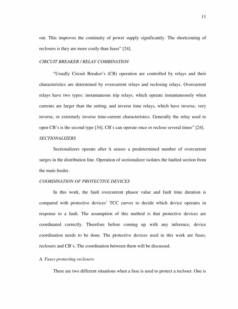
A. Fuses protecting reclosers
There are two different situations when a fuse is used to protect a recloser. One is
12
the recloser clearing temporary faults and the fuse clearing permanent faults. The other
one is the fuse clearing both temporary and permanent faults. Obviously the first one is
better, because it reduces the outage time of the distribution circuit and saves the time to
exchange fuses. But when a lateral carrying a rather small current goes away from the
primary feeder with a rather large current, the first kind of coordination is unrealistic.
Then the second coordination method is needed. Two kinds of coordination are shown in
Figure 2 [30], [31].
Figure 2. Fuses protecting reclosers.
For the first situation, the correct coordination is achieved if the minimum fault
current is larger than the intersection of the recloser’s slow curve and the fuse’s TCC,
and the maximum fault current is less than the intersection of the fuse’s MM curve and
the recloser’s fast curve.
13
For the second situation, the correct coordination is that the fuse’s TCC is always
below the recloser’s fast curve, which means the fuse always operates faster than the
recloser.
To achieve the correct coordination, some factors such as preloading, ambient
temperature, accumulated heating and cooling of the fuse should be taken into account.
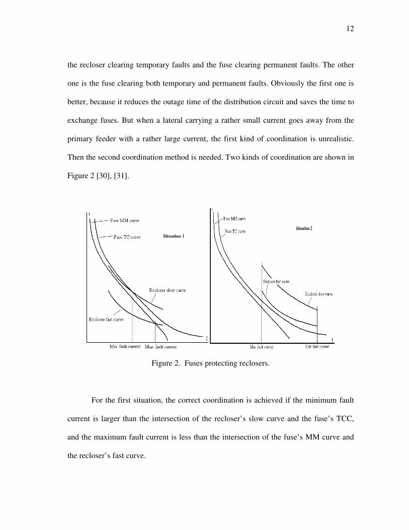
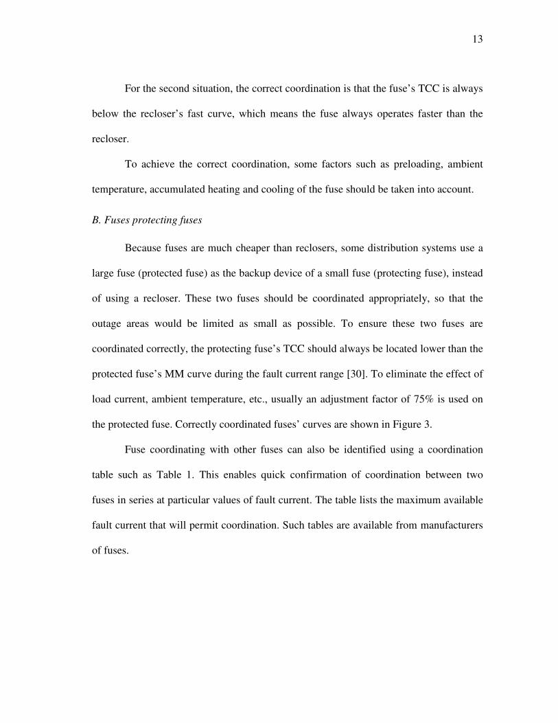
B. Fuses protecting fuses
Because fuses are much cheaper than reclosers, some distribution systems use a
large fuse (protected fuse) as the backup device of a small fuse (protecting fuse), instead
of using a recloser. These two fuses should be coordinated appropriately, so that the
outage areas would be limited as small as possible. To ensure these two fuses are
coordinated correctly, the protecting fuse’s TCC should always be located lower than the
protected fuse’s MM curve during the fault current range [30]. To eliminate the effect of
load current, ambient temperature, etc., usually an adjustment factor of 75% is used on
the protected fuse. Correctly coordinated fuses’ curves are shown in Figure 3.
Fuse coordinating with other fuses can also be identified using a coordination
table such as Table 1. This enables quick confirmation of coordination between two
fuses in series at particular values of fault current. The table lists the maximum available
fault current that will permit coordination. Such tables are available from manufacturers
of fuses.

14
Table 1. Fuse to fuse coordination table for T type fuses.
Protected fuse current rating Protecting
fuse current
rating 6 8 10 12 15 20 25 30 40 50
3 225 360 550 780 1050 1400 1750 2250 2900 3600
6 140 400 690 990 1350 1750 2250 2900 3600
8 220 560 900 1300 1650 2250 2900 3600
10 300 710 1200 1600 2200 2800 3600
12 400 910 1450 2000 2700 3500
15 1200 1800 2550 3400
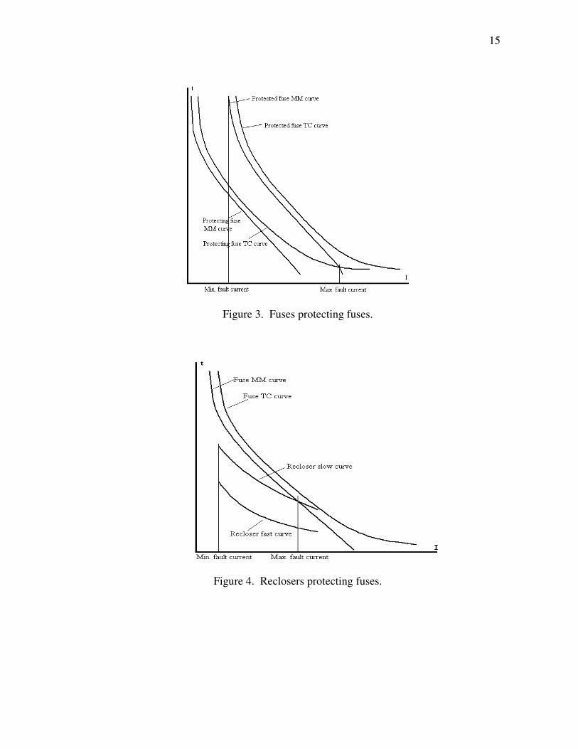
C. Reclosers protecting fuses
Usually this kind of coordination is used at substation transformer primary side
and secondary side. The fuse provides protection for the transformer against a fault in
the transformer or at the transformer terminals and also provides backup protection for
the recloser. The recloser should clear all kinds of downstream faults (temporary &
permanent), and the fuse only protects the transformer [30]. The correct coordination is
that the recloser’s slow curve should be below the fuse MM curve. There is also an
adjustment factor depending on the number of fast and slow trips and the reclosing time
of the recloser. Figure 4 gives an example of this kind of coordination.
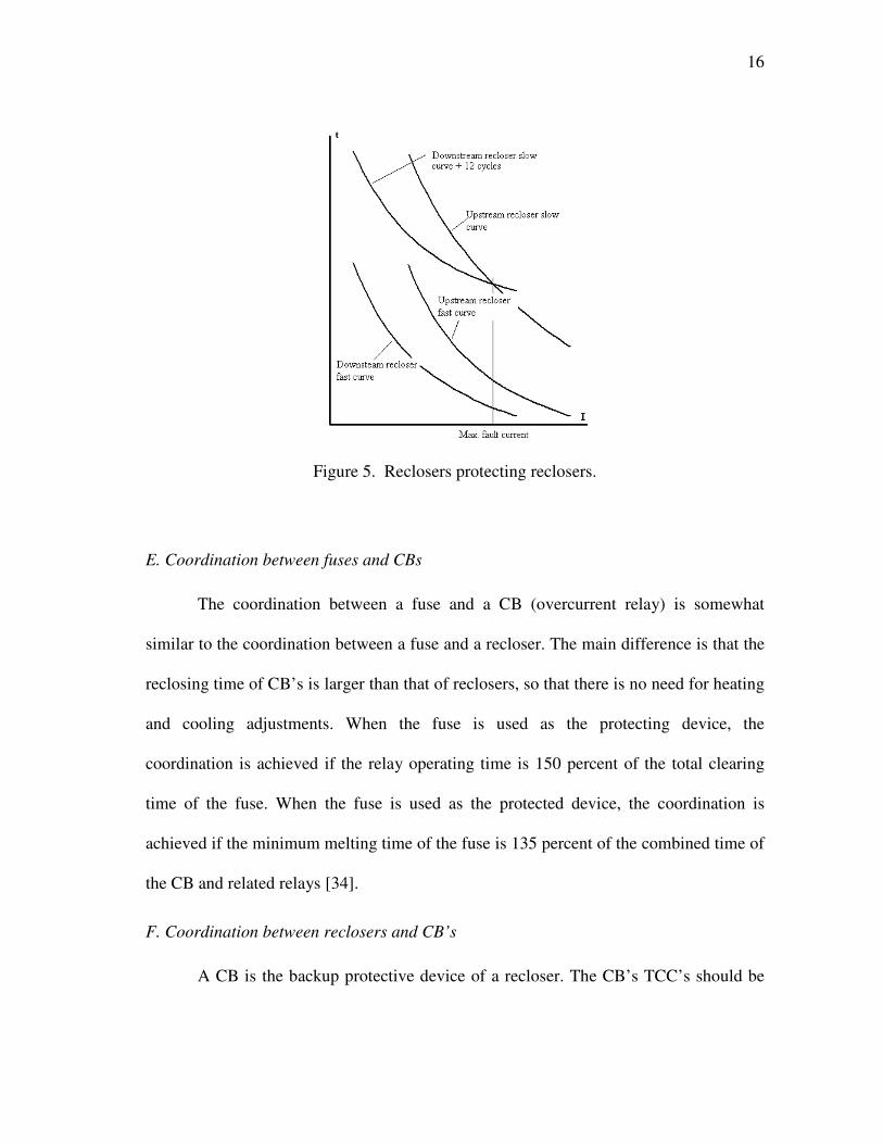
D. Reclosers protecting reclosers
While downstream smaller reclosers protect upstream larger reclosers, the correct
coordination is achieved by the requirement: the maximum fault current is less than the
intersection of the upstream slow curve and the downstream slow curve plus several
cycles (usually 12 cycles) [30], [31]. This requirement illustrates in Figure 5.
15
Figure 3. Fuses protecting fuses.
Figure 4. Reclosers protecting fuses.
16
Figure 5. Reclosers protecting reclosers.
E. Coordination between fuses and CBs
The coordination between a fuse and a CB (overcurrent relay) is somewhat
similar to the coordination between a fuse and a recloser. The main difference is that the
reclosing time of CB’s is larger than that of reclosers, so that there is no need for heating
and cooling adjustments. When the fuse is used as the protecting device, the
coordination is achieved if the relay operating time is 150 percent of the total clearing
time of the fuse. When the fuse is used as the protected device, the coordination is
achieved if the minimum melting time of the fuse is 135 percent of the combined time of
the CB and related relays [34].
F. Coordination between reclosers and CB’s
A CB is the backup protective device of a recloser. The CB’s TCC’s should be
17
higher than those of the recloser. A crucial factor to achieve the coordination is the reset
time of overcurrent relays during the tripping and reclosing sequence. The coordination
must ensure a mechanical relay cannot accumulate enough movement in the trip
direction during recloser successive operations to trigger a false tripping. Digital relays
must also be protected from false tripping through proper coordination.
G. Coordination between sectionalizers and reclosers
Better coordination of sectionalizers with other protective devices depends on
three factors. The first factor is that only overcurrent surges resulting from load side fault
current are to be sensed. This means that sectionalizer’s actuating current must be less
than the upstream device minimum trip settings. The second factor involves setting the
number of overcurrent counts to trip open. Sectionalizer setting should be one less than
lockout setting of upstream protective device. The third factor is that sectionalizer’s
memory time must be no longer than the cumulative tripping and reclosing time intervals
of the upstream protective device.
INFLUENCE OF TEMPERATURE IN COORDINATION OF DEVICES
“The combinational presence of fuse and reclosers in the feeder increases the
temperature effects on the coordination of these devices. The application of reclosers on
electrical distribution systems requires them to be coordinated with both source side and
load side fuses. In either case, fault current through the fuse will be interrupted by the
recloser and then restored as the recloser progresses through its operating sequence. At
the start, the temperature of the fuse element is determined by the pre-fault load current
and by the ambient temperature. When there is a fault, the temperature of the fuse
18
element increases towards its melting point value. If the recloser open occurs before the
fuse elements melting value, temperature of fuse will cool down during the reclosing
time interval. This cycle will continue until the fault is cleared prior to the next reclosing
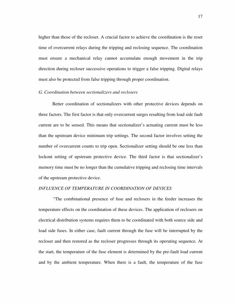
operation, fuse melts and clears the fault or the recloser operates to lockout” [25]. Figure
6 illustrates the heating and cooling effect of the fuse element”.
Figure 6. Heating and cooling of fuse during recloser’s operating sequence [25].
“This repeated heating and cooling effects of fuse element is to be considered
while coordinating the protective devices. We need to make necessary adjustments of
TCC curve data to include the influence of this heating and cooling effect. When we
include both the heating and cooling effects, recloser curves can be precisely adjusted to
reflect these and equivalent recloser TCC curves seen by the fuse. Effects of heating and

19
cooling for fuses can vary substantially” [25]. This is illustrated by Figure 7. In this
figure, after a reclosing time interval of 2 seconds has elapsed, the slow speed fuse 20 T
has lost 13 % of its heat input as compared to that of very fast speed fuse 40 N, which
has lost 92% of its heat input.
Figure 7. Cooling factors versus time for different fuse links [25].
“In source side fuse and load side recloser case, the maximum current up to
which accurate coordination occurs is determined by lower of maximum interrupting
rating recloser or fuse and the intersection of minimum melting curve of the fuse and
maximum equivalent operating TCC curve of the recloser. For better coordination, heat
stored in the fuse needs to be compensated when the recloser contacts are closed and the
heat lost when the contacts are open. At a particular chosen current value, the heat stored

20
in the fuse when recloser contacts are closed is directly proportional to recloser’s
clearing time. So the necessary adjustments can be made to fast and slow curves of
recloser by using cooling factor C to the clearing time” [25]. Hence the maximum
lockout curves for the recloser, for various operating sequences are obtained as,
For one operation of recloser,
Tl = TR1 / (1-P) (1)
For two operations of recloser,
Tl = (TR1C1 + TR2 ) / (1-PC1) (2)
For three operations of recloser,
Tl = (TR1C1 C2 + TR2 C2 + TR3 ) / (1-PC1 C2) (3)
Similarly for four operations of recloser,
Tl = (TR1C1 C2 C3 + TR2 C2 C3 + TR3 C3 + TR4) / (1-PC1 C2 C3) (4)
These equivalent lockout curves and manufacturers TCC curves for fuses are
used in conjunction in this work to estimate the coordination between the protective
devices [25].
In this chapter, description of different protective devices, their basic modeling
approach, coordination of these protective devices during fault conditions and influence
of temperature effects were presented. Following chapter will introduce the device
identification problem, authors approach and details of operated device estimation
framework implementation.

21
CHAPTER IV
PROTECTIVE DEVICE ESTIMATION FRAMEWORK
PROBLEM FORMULATION
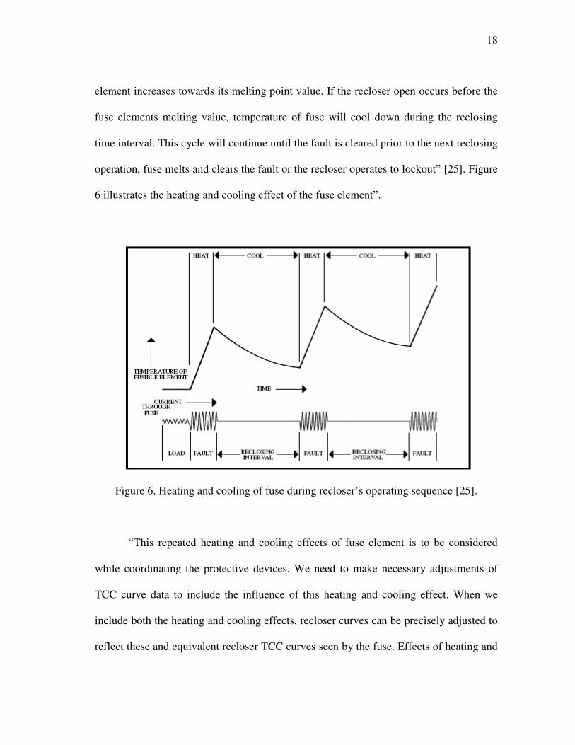
An electric power distribution system is that part of an electric utility system
between the bulk power source and the consumers’ service switches [34]. Figure 8
shows a simplified diagram of a typical distribution system. Distribution systems can be
divided in various parts, namely, sub-transmission circuits, distribution substations,
distribution or primary feeders, distribution transformers, secondary circuits and service
drops. Each distribution substation serves its own load area. The area served by the
distribution substation is subdivided and a primary feeder, usually operating in the range
of 4.6 to 34.5kV, supplies each subdivision. The primary feeder normally consists of
either a three phase, three wire or a three phase, four wire main that runs from the
substation to the load center where it branches into three-phase sub feeders and single-
phase laterals. The distribution transformers are connected to the primary feeders, sub-
feeders, and laterals usually through fused cutouts, and supply the secondary circuits to
which the consumers’ services are connected [34].
22
Figure 8. One-line diagram of a typical distribution system.
Most feeders in the distribution system are radial, which means that the
electricity flows only through one path from the source to each customer [32]. A feeder
may consist of a three-phase primary feeder, laterals (three-phase, two-phase or single-
phase), loads, transformers, shunt capacitor banks, and protective devices. These
equipments age over time, and this may lead to defects. Furthermore, most distribution
systems are overhead systems, which are easily affected by changing weather conditions,
23
animals, and traffic accidents and hence power system faults and other abnormal events
are inevitable. Any such power system events are interrupted by a protection device to
isolate the faulted section and minimize the impact on the overall system. Ultimately
only one of the protective devices interrupts the short circuit condition. But many such
protective devices connected in the system senses the fault and the operation of
particular protective device is determined by the coordination of these protective
devices, such as fuse to fuse coordination, recloser to fuse coordination and recloser to
recloser coordination [33], [34].
The power monitoring devices installed in the substations as a part of DFA
project, gathers various phasor voltage and current data whenever any abnormal power
system event occurs. The voltage variations provide the main data in terms of the power
quality problems the customers will see on the feeder, which are usually the voltage sags
and interruptions. However, for our diagnostic purposes, i.e., to determine what
happened, the Over Current (OC) waveforms provide more information [30]. One of the
major diagnostic analyses involves the identification of the protective devices operated
as a response to a disturbance. It is also important to detect any equipment failures or
coordination problems. This is very tedious and challenging because
- To perform proper analysis the substation personnel need to have
complete knowledge about the protection devices installed on the
system, protection scheme utilized and coordination of each feeder.
24
- A typical power system disturbance might create multiple data records.
Hence manual screening of these records is time consuming and needs
dedicated substation personnel.
Many AI-based methods published usually estimates the device that operated and locate
faults based data fed from SCADA systems, fault detectors, and communication
channels. Due to economic constraints, the communication between protective devices
and the substation are limited to some important substations. For many systems,
measurements are only available at the substation and the operation status of feeder
protective devices is unknown. For such systems, these methods are not feasible. Also,
many expert system-based methods locate faults by using information obtained from
SCADA systems, the network map and the dispatcher’s past experience. Therefore,
these methods are customized to one particular system and difficult to apply to different
distribution systems. This calls for development of algorithm for estimating the device
that operated independent of data from SCADA systems and experts involvement.
In order to overcome the problems mentioned above, this work presents
development of a new device estimation framework for radial distribution systems that
utilizes relevant data from substation measurements.
PROTECTIVE DEVICE ESTIMATION APPROACH
Power quality monitoring devices in the substation capture both the current and
voltage waveforms of each phase whenever the monitored feeder values falls outside
their predefined threshold settings. Figure 9 shows typical event record captured using
the DFA monitoring system. Overcurrent events are captured if the current values

25
exceed the predefined thresholds. The aim here is to use the OC event records to
determine which protection device has operated in response to an observed OC event
using these data capture record and device TCC data.
Figure 9. Typical power system event data capture record.
26
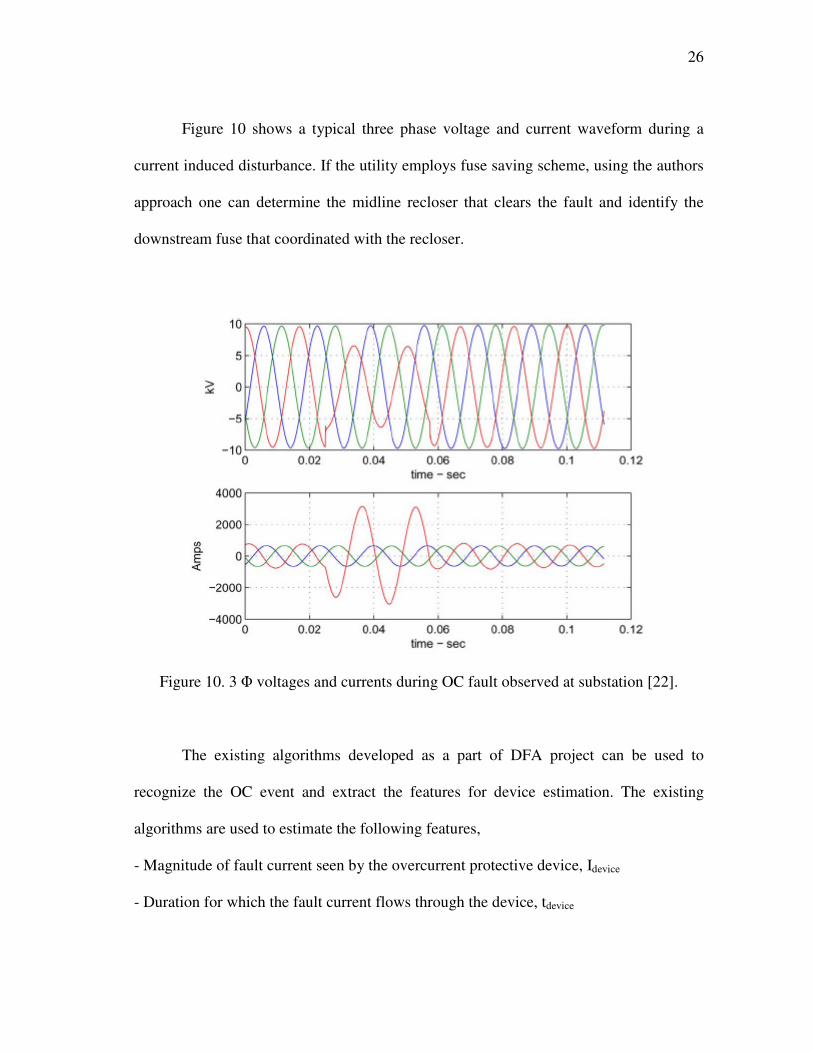
Figure 10 shows a typical three phase voltage and current waveform during a
current induced disturbance. If the utility employs fuse saving scheme, using the authors
approach one can determine the midline recloser that clears the fault and identify the
downstream fuse that coordinated with the recloser.
Figure 10. 3 Φ voltages and currents during OC fault observed at substation [22].
The existing algorithms developed as a part of DFA project can be used to
recognize the OC event and extract the features for device estimation. The existing
algorithms are used to estimate the following features,
- Magnitude of fault current seen by the overcurrent protective device, Idevice
- Duration for which the fault current flows through the device, tdevice

27
- I2t of fault event
“These parameters will then be compared with the device TCC data. The device
operating point (Idevice, tdevice) must be with in the fuse’s minimum melting time and
maximum clearing time in the case of a fuse operation or on the recloser’s fast or
delayed curve in the case of recloser operation. In addition, the I2t of the fault event must
be higher than the specified by the device manufacturer. The protective device which
satisfies the above criteria is the one that operated to clear the fault” [22].
A. Estimating fault duration seen by protective device
“TCC curves of a protective device specify how fast the device responds to the
OC fault condition. Most distribution protective devices have inverse time–current
curves and hence higher the current magnitude faster the device reacts to it. The time
duration during which the fault current flows in the device can be estimated directly
from the faulted voltage and current waveforms. It is the duration of the voltage sag or
the duration during the high current magnitude” [22]. The exact duration is determined
by using existing feature estimating algorithms developed as part of DFA project in
PSAL, Texas A&M University.
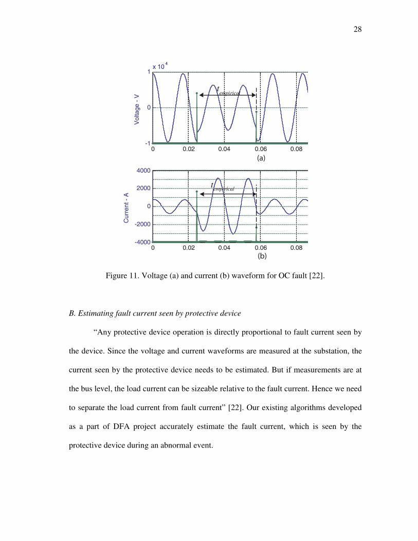
Figure 11 shows voltage and current waveform data in which fault current flows
in the protective device between 0.024 and 0.057 seconds, which is 0.033 seconds.
28
Figure 11. Voltage (a) and current (b) waveform for OC fault [22].
B. Estimating fault current seen by protective device
“Any protective device operation is directly proportional to fault current seen by
the device. Since the voltage and current waveforms are measured at the substation, the
current seen by the protective device needs to be estimated. But if measurements are at
the bus level, the load current can be sizeable relative to the fault current. Hence we need
to separate the load current from fault current” [22]. Our existing algorithms developed
as a part of DFA project accurately estimate the fault current, which is seen by the
protective device during an abnormal event.
29
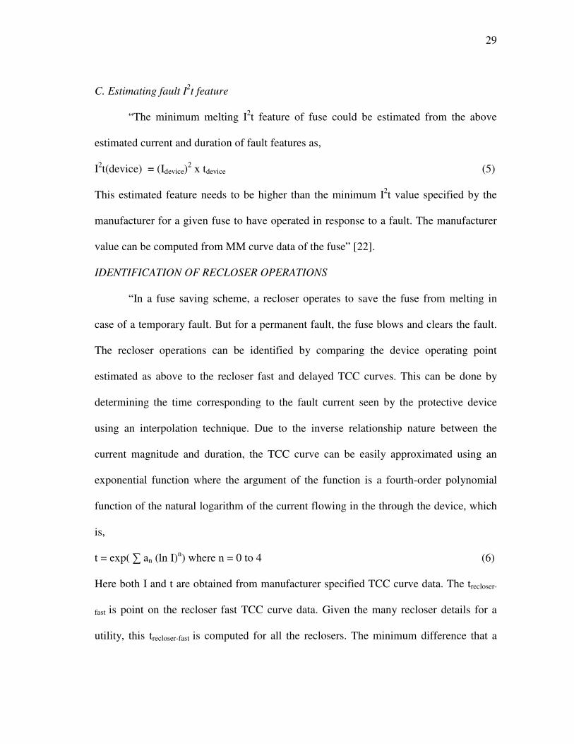
C. Estimating fault I2t feature
“The minimum melting I2t feature of fuse could be estimated from the above
estimated current and duration of fault features as,
I2t(device) = (Idevice)
2 x tdevice (5)
This estimated feature needs to be higher than the minimum I2t value specified by the
manufacturer for a given fuse to have operated in response to a fault. The manufacturer
value can be computed from MM curve data of the fuse” [22].
IDENTIFICATION OF RECLOSER OPERATIONS
“In a fuse saving scheme, a recloser operates to save the fuse from melting in
case of a temporary fault. But for a permanent fault, the fuse blows and clears the fault.
The recloser operations can be identified by comparing the device operating point
estimated as above to the recloser fast and delayed TCC curves. This can be done by
determining the time corresponding to the fault current seen by the protective device
using an interpolation technique. Due to the inverse relationship nature between the
current magnitude and duration, the TCC curve can be easily approximated using an
exponential function where the argument of the function is a fourth-order polynomial
function of the natural logarithm of the current flowing in the through the device, which
is,
t = exp( ∑ an (ln I)n) where n = 0 to 4 (6)
Here both I and t are obtained from manufacturer specified TCC curve data. The trecloser-
fast is point on the recloser fast TCC curve data. Given the many recloser details for a
utility, this trecloser-fast is computed for all the reclosers. The minimum difference that a
30
trecloser-fast computed from the actual tdevice estimated as above is the actual recloser
operated in response to the fault. The similar procedure is followed for slow curve when
the recloser operates in delayed curve region. The time of operation of a recloser in slow
curve is denoted as trecloser-delayed. Fuses that coordinate well for a given recloser are
chosen based on identified recloser’s TCC curves. The TCC curve of the fuse should be
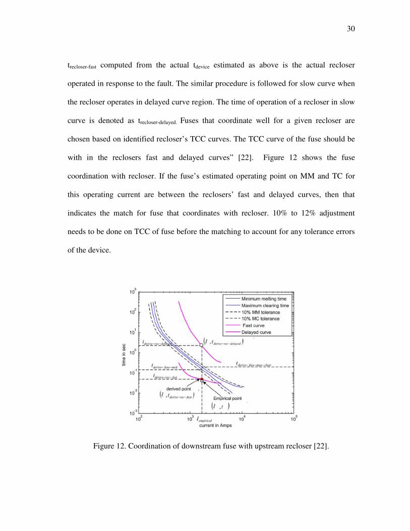
with in the reclosers fast and delayed curves” [22]. Figure 12 shows the fuse
coordination with recloser. If the fuse’s estimated operating point on MM and TC for
this operating current are between the reclosers’ fast and delayed curves, then that
indicates the match for fuse that coordinates with recloser. 10% to 12% adjustment
needs to be done on TCC of fuse before the matching to account for any tolerance errors
of the device.
Figure 12. Coordination of downstream fuse with upstream recloser [22].

31
IDENTIFICATION OF FUSE OPERATIONS
“Whenever a permanent fault occurs, a fuse should blow to isolate the faulted
section from the rest of distribution network. The tdevice estimated should be with in the
fuse MM and TC time for the given Idevice. This matching is verified by estimating the
tfuse-melt and tfuse-clear for the given fault current. Figure 13 shows such a match.
tfuse-melt <= tdevice <= tfuse-clear (7)
When we have many fuses satisfying the above criteria, especially for high value of fault
currents due to overlap of TCC data of fuses, both the match using equation (7) and
match with I2t criteria estimates the exact operation of fuses” [22]. Even then some of
the fuses overlap and thus cannot be accurately identified by this approach. In future
work, the author plans to implement fuzzy logic to give weights for each fuse and
develop fuzzy rules for exact identification.
Figure 13. Matching fault point to fuse operation [22].

32
In this chapter, importance of device estimation and author approach in
identifying fuse and recloser operations during overcurrent fault conditions was
presented. In the next chapter, software implementation of the algorithm is presented.
33
CHAPTER V
SOFTWARE IMPLEMENTATION
Software systems developed for power systems are much complicated because of
use of function-oriented development methodologies. In these methodologies, the
emphasis is given to functionality and hence overall application is built over by many
application modules which makes the software system to be unmanageable and
necessitates expensive maintenance. But the use of object oriented design methodologies
has proven track record of supporting future enhancements and ease of maintenance
[35]. In this methodology, development consists of three different stages - analysis,
design and implementation. During each of this stage, we use three different kinds of
models to represent the system: object model, dynamic model and functional model. The
static structure of objects in the system and their relationships are represented by the
object model, aspects that change over time are represented by dynamic models and
functional model presents the data transformation of the system. Although the complete
description of software requires explanation of all the three models, only the object
modeling is addressed here which forms the basis of implementation. The primary
purpose of object modeling is to represent objects, which binds data and behavior in to
single entity. The objects with similar properties, operations and relationships to other
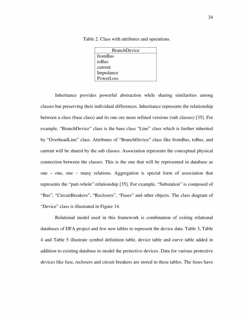
objects are grouped in to a class. Table 2 presents the “BranchDevice” class. There exits
three different types of relationships among the different objects namely, inheritance,
association and aggregation.
34
Table 2. Class with attributes and operations.
BranchDevice
fromBus
toBus
current
Impedance
PowerLoss
Inheritance provides powerful abstraction while sharing similarities among
classes but preserving their individual differences. Inheritance represents the relationship
between a class (base class) and its one ore more refined versions (sub classes) [35]. For
example, “BranchDevice” class is the base class “Line” class which is further inherited
by “OverheadLine” class. Attributes of “BranchDevice” class like fromBus, toBus, and
current will be shared by the sub classes. Association represents the conceptual physical
connection between the classes. This is the one that will be represented in database as
one – one, one – many relations. Aggregation is special form of association that
represents the “part-whole” relationship [35]. For example, “Substation” is composed of
“Bus”, “CircuitBreakers”, “Reclosers”, “Fuses” and other objects. The class diagram of
“Device” class is illustrated in Figure 14.
Relational model used in this framework is combination of exiting relational
databases of DFA project and few new tables to represent the device data. Table 3, Table
4 and Table 5 illustrate symbol definition table, device table and curve table added in
addition to existing database to model the protective devices. Data for various protective
devices like fuse, reclosers and circuit breakers are stored in these tables. The fuses have

35
one-one relation in both device table and curve table, where as reclosers have one-one
relationship with device table but one-many relationship with curve table.
Figure 14. Class diagram of developed object model.
Table 3. Symbol definition.
Symbol Definition
P Pointer to object of type component
s_curve Pointer to an object of type protective
curve
s_device Pointer to an object of type protective
device
36
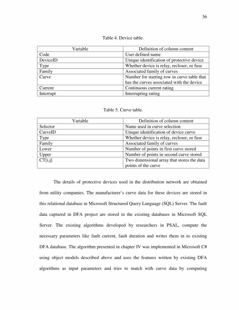
Table 4. Device table.
Variable Definition of column content
Code User defined name
DeviceID Unique identification of protective device
Type Whether device is relay, recloser, or fuse
Family Associated family of curves
Curve Number for starting row in curve table that
has the curves associated with the device
Current Continuous current rating
Interrupt Interrupting rating
Table 5. Curve table.
Variable Definition of column content
Selector Name used in curve selection
CurveID Unique identification of device curve
Type Whether device is relay, recloser, or fuse
Family Associated family of curves
Lower Number of points in first curve stored
Upper Number of points in second curve stored
CT[i,j] Two dimensional array that stores the data
points of the curve
The details of protective devices used in the distribution network are obtained
from utility companies. The manufacturer’s curve data for these devices are stored in
this relational database in Microsoft Structured Query Language (SQL) Server. The fault
data captured in DFA project are stored in the existing databases in Microsoft SQL
Server. The existing algorithms developed by researchers in PSAL, compute the
necessary parameters like fault current, fault duration and writes them in to existing
DFA database. The algorithm presented in chapter IV was implemented in Microsoft C#
using object models described above and uses the features written by existing DFA
algorithms as input parameters and tries to match with curve data by computing

37
minimum distance for the operating point identified as explained in Chapter IV.
Implementation is a two tier model where the data resides in SQL data tier and business
tier written in Microsoft C# performs the necessary computation based on device
coordination and fault operating point. Results will be written to a text/log file. The use
of Microsoft C# helps in future enhancement to web based application.
In this chapter, object oriented software implementation of device estimation was
presented. In the next chapter, some of the test cases and results obtained by using the
authors approach will be discussed.
38
CHAPTER VI
RESULTS AND DISCUSSIONS
The device estimation algorithm was implemented in object oriented software
framework and evaluated using simulated and actual test data. “Simulation data are
generated using Matlab with 12-MVA substation transformer (115/12.47 kV) that serves
three 12.47-kV main feeders. The voltage and current measurements are taken at the
secondary of the transformer. Therefore, the measured current is the total load current of
all the three feeders. The total load on each feeder is approximately 3.2 MVA with a
power factor of 95%” [22]. The device models are developed using the approach
discussed in [31].
CASE A
“In this case, recloser operation will be simulated in which phase ‘A’ pick up
element recognizes the fault. With assumption that there exist fuse saving scheme, a
temporary single line to ground fault is simulated on single phase lateral tap off the main
feeder. The lateral is assumed to be protected with 65 T fuse link and recloser on the
main feeder. The recloser (three-phase trip and three-phase lockout) has phase and
ground pickup currents of 560 A and 280 A, respectively. The recloser operating
sequence is 2-fast and 2-delayed. In the simulation, the 560-A phase pickup relay was
chosen to clear the temporary fault in two fast and one delayed operations. The
simulated fault current flowing in the recloser was 2.1 kA, and it tripped after 0.04 s for
its first fast-trip operation” [22].
39
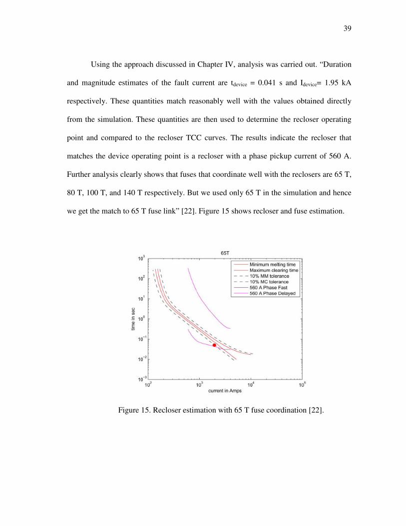
Using the approach discussed in Chapter IV, analysis was carried out. “Duration
and magnitude estimates of the fault current are tdevice = 0.041 s and Idevice= 1.95 kA
respectively. These quantities match reasonably well with the values obtained directly
from the simulation. These quantities are then used to determine the recloser operating
point and compared to the recloser TCC curves. The results indicate the recloser that
matches the device operating point is a recloser with a phase pickup current of 560 A.
Further analysis clearly shows that fuses that coordinate well with the reclosers are 65 T,
80 T, 100 T, and 140 T respectively. But we used only 65 T in the simulation and hence
we get the match to 65 T fuse link” [22]. Figure 15 shows recloser and fuse estimation.
Figure 15. Recloser estimation with 65 T fuse coordination [22].
40
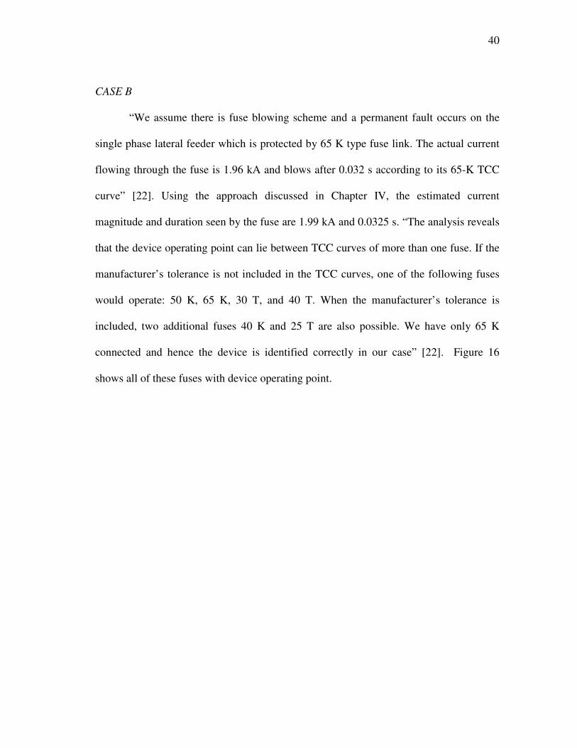
CASE B
“We assume there is fuse blowing scheme and a permanent fault occurs on the
single phase lateral feeder which is protected by 65 K type fuse link. The actual current
flowing through the fuse is 1.96 kA and blows after 0.032 s according to its 65-K TCC
curve” [22]. Using the approach discussed in Chapter IV, the estimated current
magnitude and duration seen by the fuse are 1.99 kA and 0.0325 s. “The analysis reveals
that the device operating point can lie between TCC curves of more than one fuse. If the
manufacturer’s tolerance is not included in the TCC curves, one of the following fuses
would operate: 50 K, 65 K, 30 T, and 40 T. When the manufacturer’s tolerance is
included, two additional fuses 40 K and 25 T are also possible. We have only 65 K
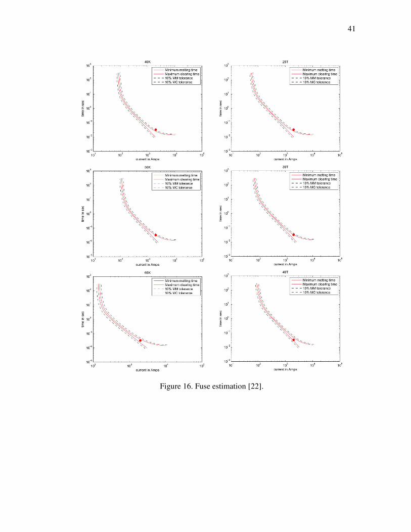
connected and hence the device is identified correctly in our case” [22]. Figure 16
shows all of these fuses with device operating point.
41
Figure 16. Fuse estimation [22].
42
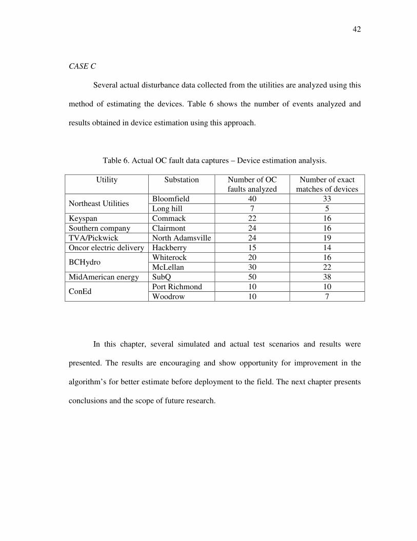
CASE C
Several actual disturbance data collected from the utilities are analyzed using this
method of estimating the devices. Table 6 shows the number of events analyzed and
results obtained in device estimation using this approach.
Table 6. Actual OC fault data captures – Device estimation analysis.
Utility Substation Number of OC
faults analyzed
Number of exact
matches of devices
Bloomfield 40 33 Northeast Utilities
Long hill 7 5
Keyspan Commack 22 16
Southern company Clairmont 24 16
TVA/Pickwick North Adamsville 24 19
Oncor electric delivery Hackberry 15 14
Whiterock 20 16 BCHydro
McLellan 30 22
MidAmerican energy SubQ 50 38
Port Richmond 10 10 ConEd
Woodrow 10 7
In this chapter, several simulated and actual test scenarios and results were
presented. The results are encouraging and show opportunity for improvement in the
algorithm’s for better estimate before deployment to the field. The next chapter presents
conclusions and the scope of future research.
43
CHAPTER VII
CONCLUSIONS AND FUTURE WORK
A protective device estimation framework has been developed using protective device
manufacturer’s data and features estimated during fault conditions to identify the
operation of protective devices in response to faults. Estimation and analysis techniques
are proposed to detect and identify fuse and recloser operations on distribution feeders.
These techniques are intended to further evaluate performance coordination of
overcurrent protective devices and help locate faults on the feeder. This diagnostic
framework needs waveform data collected from the substation, feature estimates during
fault conditions, the utility fault-clearing scheme, and TCC’s of the different protective
devices. Feeder topology is not needed for analysis. As the analysis is only based on the
current and voltage measurements at the substation, this new scheme can be used for
almost all distribution systems. Also, the different test cases presented show the
effectiveness of the technique. Results are promising and show that further
improvements to the algorithms could lead to real world use. However, there exist
uncertainties in identifying closely related devices when all of their operating points
match the calculated operating point. These uncertainties can be modeled by fuzzy
membership functions which should be considered in future research.
44
REFERENCES
[1] P.M. Anderson, “Power system protection,” IEEE Press, vol. 1, pp. 16-98, 1998.
[2] G.E. Hage, R.N. Medicine Bear, A.S. Baum, “Automated distribution fault
locating system,” IEEE Trans. on Industry Applications, vol. 32, no. 3, pp. 704-
708, May-June 1996.
[3] A.A. Girgis, M.B Johns, “A hybrid expert system for faulted section
identification fault type classification and selection of fault location algorithms,”
IEEE Trans. on Power Delivery, vol. 4, no. 2, pp. 978-985, April 1989.
[4] M. Lehtonen, S. Pettissalo, J.-H. Etula, “Calculational fault location for electrical
distribution networks,” Proceedings of Third International Conference on Power
System Monitoring and Control, London, vol. 1, pp. 38-43, Jun. 1991.
[5] F. Eickhoff, E. Handschin, W. Hoffmann, “Knowledge based alarm handling and
fault location in distribution networks,” IEEE Trans. on Power Systems, vol. 7,
no. 2, pp. 770-776, May 1992.
[6] Y. H. Yuan, F. C. Lu, Y. Chien, J. P. Liu, J. T. Lin, P. H. S. Yu, R. R. T Kuo,
“An expert system for locating distribution system faults,” IEEE Trans. on
Power Delivery, vol. 6, no.1, pp. 366-372, Jan. 1991.
[7] M. Zhou, G. Li, J. Ren, K. Xu, Y. Sun, “A distributed power system fault
diagnosis expert system based on fuzzy inference,” Proceedings of International
Conference on Advances in Power System Control, Operation and Management,
Geneva, vol. 1, pp. 264-268, 2000.

45
[8] C.S. Chang, J.M. Chen, D. Srinivasan, F.S. Wen, A.C. Liew, “Fuzzy logic
approach in power system fault section identification,” IEE Proceedings -
Generation, Transmission and Distribution, vol. 144, no. 5, pp. 406-414, Sept.
1997.
[9] P.R. Silva, A.J. Santos, F.G. Jota, “An intelligent system for automatic detection
of high impedance faults in electrical distribution systems”, Proceedings of the
38th
Midwest Symposium on Circuits and Systems, Pullman, WA, vol. 1, pp. 453-
456, 1996.
[10] C. Jian-Liang, N.D. Rao, “A fuzzy expert system for fault diagnosis in electric
distribution systems,” Proceedings of Canadian Conference on Electrical and
Computer Engineering, Vancouver, BC, Canada, vol. 2, pp. 1283-1286, 1993.
[11] E.M. Martinez, E.F. Richards, “An expert system to assist distribution
dispatchers in the location of system outages,” Proceedings of 35th Annual
Conference on Rural Electric Power, Dearborn, MI, vol. 1, pp. A2/1-A2/5, 1991.
[12] S. Kumano, N. Ito, T. Goda, Y. Uekubo, S. Kyomoto, et al. “Development of
expert system for operation at substation,” IEEE Trans. on Power Delivery, vol.
8, no. 1, pp. 56-65, Jan. 1993.
[13] J. Ypsilantis, H. Lee, and C.Y. Teo, “Adaptive, rule based fault diagnostician for
power distribution networks,” IEE Proceedings - Generation, Transmission and
Distribution, vol. 139, no. 6, Nov. 1992.
46
[14] C.Y. Teo, “Automation of knowledge acquisition and representation for fault
diagnosis in power distribution networks,” Electric Power Systems Research,
vol. 27, no. 3, pp. 183-189, Aug. 1993.
[15] A. S. Hadjsaid, N. Bretas, “Fault diagnosis in deregulated distribution systems
using an artificial neural network,” Proceedings of IEEE Power Engineering
Society Winter Meeting, Columbia, OH, vol. 2, pp. 821-823, 2001.
[16] Z.Q. Bo, R.K. Aggarwal, A.T. Johns, H.Y. Li, Y.H. Song, “A new approach to
phase selection using fault generated high frequency noise and neural networks,”
IEEE Trans. on Power Delivery, vol.12, no. 1, pp. 106-115, Jan. 1997.
[17] H.T. Yang, W.Y. Change, C.L. Huang, “Power system distributed on-line fault
section estimation using decision tree based neural nets approach,” IEEE Trans.
on Power Delivery, vol. 10, no. 1, pp. 540-546, Jan. 1995.
[18] T. Bi, Y. Ni, C.M. Shen, F.F. Wu, “An on-line distributed intelligent fault section
estimation system for large-scale power networks,” Electric Power Systems
Research, vol. 62, no. 3, pp. 173-182, 2002.
[19] T. Bi, Y. Ni, C.M. Shen, F.F. Wu, “Efficient multi-way graph partitioning
method for fault section estimation in large-scale power networks,” IEE
Proceedings - Generation, Transmission and Distribution, vol. 149, no. 3, pp.
289-294, May 2002.
[20] E.A. Mohamed, N.D. Rao, “Artificial neural network based fault diagnostic
system for electric power distribution feeders,” Electric Power Systems
Research, vol. 35, no. 1, pp. 1-10, Oct. 1995.
47
[21] M.T. Glinkowski, N.C. Wang, “ANN’s pinpiont underground distribution
faults,” IEEE Computer Applications in Power, vol. 8, no. 4, pp. 31-34, Oct.
1995.
[22] S. Santoso, T.A. Short, “Identification of fuse and recloser operations in a radial
distribution system,” IEEE Trans. on Power Delivery, vol. 22, No. 4, pp. 2370 –
2377, Oct. 2007.
[23] A.J. Allen, S. Santoso, “Modeling distribution overcurrent protective devices for
time-domain simulations,” IEEE Power Engineering Society Gen. Meeting,
Tampa, FL, vol. 1, pp. 1 – 6, June 2007.
[24] J. Li, K.L. Butler-Purry, C. Benner, “Modeling of TCC-based protective
devices,” IEEE PES Transmission and Distribution Conference and Exposition,
vol. 1, pp. 150 – 156, Sep. 2003.
[25] C.J. Cook, D.A. Myers, “The use of cooling-factor curves for coordinating fuses
and reclosers,” IEEE Rural Electric Power Conference, Rapid City, SD, vol. 1,
pp. C-3 – C-3-5, May 2007.
[26] G. Lampley, “Power quality monitoring to meet customer needs,” Proceedings of
EPRI Power Quality Analysis Conference, Charlotte, NC, vol. 1, pp. 3-10, May
1999.
[27] K.M. Manivannan, “Fuzzy logic based operated device identification in power
distribution systems,” M.S Thesis, Texas A&M University, May 2002.
[28] L.M. Faulkenberry, W. Coffer, Electrical Power Distribution and Transmission,
New Jersey: Prentice Hall, 1996.
48
[29] T. Gonen, Electric power distribution system engineering, New York: McGraw-
Hill, 1986.
[30] WindMil Users Guide (version 5.0), Milsoft Integrated Solutions, Inc., Abilene,
TX, 2001.
[31] W.H. Kersting, Distribution system modeling and analysis, Boca Raton, FL:
CRC Press, 2002.
[32] Electrical transmission and distribution reference book, 3rd
Edition, Pittsburgh,
PA: Westinghouse Electric & Manufacturing Co., 1944.
[33] Electrical distribution-system protection, 3rd
Edition, Pittsburgh, PA: Cooper
Power Systems, 1990.
[34] T. A. Short, Electric Power Distribution Handbook, Boca Raton, FL: CRC Press,
2004.
[35] J. Rumbaugh, M. Blaha, W. Permerlani, F.Eddy, W. Lorensen, Object oriented
modeling and design, Englewood Cliffs, NJ: Printice Hall, 1991.
[36] TCC curves, SMD power fuses, outdoor transmission,
http://www.sandc.com/support/tccs_smd_ot.asp, Accessed on Sep. 2008

49
VITA
Janarthanan Rengarajan received his B.E. degree in electrical and electronics
engineering from PSG College of Technology, Coimbatore, India in 2004. He entered
Computer Engineering graduate program at Texas A&M University in August 2006 and
graduated with his M.S. in December 2008. His research interests include computer
applications to power systems, power electronics and software engineering.
Janarthanan may be reached by email at: [email protected] or at Power
systems automation laboratory, Wisenbaker engineering research center, Department of
electrical and computer engineering, Texas A&M University, College Station, TX,
77843.