openfoam project: different ways to treat rotating geometries
TRANSCRIPT

/*-------------------------------------------------------------------------------------------------------*\======== |\\ / F ield | OpenFOAM: The Open Source CFD Toolbox \\ / O peration | \\ / A nd | Copyright held by original author \\ / M anipulation |
------------------------------------------------------------------------------------------------------------
OpenFOAM Project:
Different ways to treat rotating geometries
Developed by : Olivier petit
ApplicationicoDyMFoamturbDyMFoam
MRFSimpleFoam
\*------------------------------------------------------------------------------------------------------*/
1

Index
Index ............................................................................................................................................. 2 Introduction .................................................................................................................................... 3 Dynamic mesh changes or sliding interface. ................................................................................. 4
Short explanation of the sliding interface .................................................................................. 5 Example using the solver icoDyMFoam ................................................................................... 5 Results ....................................................................................................................................... 7 Computing the same example in turbDyMFoam ....................................................................... 8 Particularities of a mesh modifier .............................................................................................. 9 Conclusions and remarks about the mesh modifiers ............................................................... 11
Multi reference frames, or MRFSimpleFoam .............................................................................. 12 MixerVessel2D ........................................................................................................................ 12
Launching mixerVessel2D .................................................................................................. 12 Tutorial: improvement of the mixerVessel2D ..................................................................... 14
Conclusion about MRFSimpleFoam ....................................................................................... 14 Conclusions .................................................................................................................................. 14 References .................................................................................................................................... 15
2

Introduction
C.F.D is used nowadays almost everywhere. It reduces the cost of experiments and allows a better understanding of the reality. In some areas, such as turbo machinery, using C.F.D can be a challenge.
Often in turbo machinery, non rotational parts meet rotational parts. A typical example can be a rotor/stator situation, the rotor being the rotational part and the stator the non rotational one (see fig. 1)
Figure 1: Rotor/stator situation.
An important question for this case is how is it possible to compute both parts simultaneously? In OpenFoam, there are 3 different way to do so:
• using a moving mesh ( principle used in icoDyMFoam for incompressible, non turbulent flow and in turbDyMFoam for incompressible, turbulent flow)
• defining multi reference frames (the idea behind MRFSimpleFoam, for incompressible turbulent flow)
• GGI ( General Grid Interface), still in development.
The goal of this tutorial is to give a better understanding of the moving mesh (particularly the sliding interface) and multi reference frames by pointing out some of the particularities for the different solvers. In order to do so, a common case will be used, the mixer2D.
3

This tutorial uses both the Open-C.F.D version of OpenFoam 1.4.1 as well as the development version created by Hrvoje Hjasak, named OpenFoam 1.4.1-dev.
Both versions can be found in the Chalmers catalog at the following address:• cd /chalmers/sw/unsup64/OpenFOAM/
In case of running on a 32 bit version the same repertories can be found in • cd /chalmers/sw/unsup/OpenFOAM/
It is then important to write in the bashrc or cshrc file the 2 following lines:
For a 64- bit machine
vi ~/.bashrc
. /chalmers/sw/unsup64/OpenFOAM/OpenFOAM-1.4.1-dev/.OpenFOAM-1.4.1-dev/bashrc# . /chalmers/sw/unsup64/OpenFOAM/OpenFOAM-1.4.1/.OpenFOAM-1.4.1/bashrc
For a 32 bit machine.
vi ~/.bashrc
. /chalmers/sw/unsup/OpenFOAM/OpenFOAM-1.4.1-dev/.OpenFOAM-1.4.1-dev/bashrc# . /chalmers/sw/unsup/OpenFOAM/OpenFOAM-1.4.1/.OpenFOAM-1.4.1/bashrc
Remember then to switch between the two lines if using the development version instead of the Open C.F.D version.
Dynamic mesh changes or sliding interface.
There are three different kinds of mesh modifiers available in OpenFoam:
• attach/detach boundary : this mesh modifier is taking a face and separates it into two different boundary faces, that will be detached and attached again
• the layer addition-removal: a layer addition/removal mesh modifier will add a layer of cells in front of it once the thickness goes over the given threshold and remove a layer of cells if the layer thickness goes below the minimum
• the sliding interface : the idea behind the sliding interface is that the mesh is made of two different pieces that will be merged. In order to do so, a set of boundary faces on each side is listed.
The sliding interface is the most complex of all the mesh modifiers, but it is the most complete one. The code behind the sliding interface is too big to explain it all in this tutorial, so the main goal of this tutorial is to give some hints on how it works and where to find the different parts that are used in the sliding interface, and ultimately point out some important assumptions.
4
Short explanation of the sliding interface
As explained above, the idea of a sliding interface is to create a mesh in two pieces and identify two patches facing each other. A sliding interface should then operate on patch faces in the following way:
• project all points of the “slave” patch onto the master. The rule is that a master patch preserves its shape. Most of the time if one part is not moving and the other one rotating, the rule is that the rotating one is the slave one.
• identify the part of the patches where master and slave overlap. For those faces, the original master and slave boundary should be replaced by a set of faces internal to the mesh.
• if there exists a part of the master part which is uncovered, it should remain in the master boundary patch and support the specified boundary condition.
• the same applies for the slave patch• if the two meshes move relative to each other, the sliding interface should be able to
recover the original definition(faces) and re-couple the meshes.
All those topological changes in the mesh are done through 9 basic operations which allow all possible changes: add/modify/remove point, face or cell. The classes that describe this live in:/chalmers/sw/unsup64/OpenFOAM/OpenFOAM-1.4.1-dev/src/dynamicMesh/polyTopoChange
All those changes happen during the simulation, and the user shouldn’t have to worry about those topoActions. At each time step, the job of a mesh modifier is then to decide whether it wants to change the mesh topology, and if yes, fill in a polyTopoChange with topoActions that describe the change.
Example using the solver icoDyMFoam
To see how the sliding interface is used, an example called mixer2D is used. This example can be found in the tutorials of the OpenFoam-1.4.1-dev.The first step is to copy it into your run catalog, after having checked that the bashrc file points out to the development version.cp -r /chalmers/sw/unsup/OpenFOAM/OpenFOAM-1.4.1-dev/tutorials/icoDyMFoam/mixer2D/ ~/OpenFOAM/username-1.4.1-dev/run/
icoDyMFoam is a solver based on icoFoam. The major changes between icoFoam and icoDyMFoam can be investigated with the linux command diff:
cd /chalmers/sw/unsup/OpenFOAM/OpenFOAM-1.4.1-dev/ applications/solvers/incompressiblediff icoFoam/icoFoam.C icoDyMFoam/icoDyMFoam.C | more
The main differences lie in the updating of the mesh at each time step. Looking at the user folder in the run/mixer2D catalog, there is a new dictionary called dynamicMeshDict. This dictionary defines the movement of the geometry:
5

dynamicFvMeshLibs 1("libtopoChangerFvMesh.so"); //call a dictionary when needed.
dynamicFvMesh mixerFvMesh; //class that defines the topoChangerFvMesh
mixerFvMeshCoeffs{ coordinateSystem { type cylindrical; origin (0 0 0); axis (0 0 1); direction (1 0 0); }
rpm 10; //coefficients that defines the rotation
slider { inside insideSlider; outside outsideSlider; the two different sliders defining
which part of the mesh rotates }}
The coordinateSystem defines the type of system we are in: in this case the system is cylindrical, its origin is (0 0 0) the axis of the rotation is z. Using a cylindrical system, one needs three coordinates: r,z,ө. The direction gives an axis that defines this angle. The definition of the direction does not matter so much, as long as it has the right angle with the axis of rotation, that is to say if the axis of rotation is z, then all axis perpendicular to z can be defined as direction.The two different sliders are important as well, they define the rotating part. Per definition, as written in the code, inside defines the slider that is moving, and outside the one that is fixed.
There are at the moment 5 different kinds of topoChanger in OpenFoam, and they can be found in /Chalmers/sw/unsup/OpenFOAM/OpenFOAM-1.4.1/src/topoChangerFvMesh.Those classes define the change (rotation translation or else) that the geometry and therefore the mesh will go through.
If computing it in the usual way, blockMesh . mixer2DicoDyMFoam . mixer2D You can see the mesh moving as it does along the slider in figure 3.
In order to know exactly which part of the geometry is to be modified, the cells and faces that are concerned are investigated, and then gathered together as zones. This is a very important and recurrent way of programming and gathering all parts of mesh that one wants to play with. The same way of programming is used in the multi reference frame.
6

The time folders are written as described in the system/controlDict. Inside those folders, one can have a look at the file inside polymesh: vi time/polymesh/meshmodifiers.gz. In this file the master and slave parts are defined as well as the kind of mesh modifier used and other properties. It is wise not to change this file.
Results
Figure 2: geometry of the mixer2D
7

Figure 3: caption of the moving mesh
Computing the same example in turbDyMFoam
Using the sliding interface in turbDyMFoam is pretty straight forward once the basics of icoDyMFoam has been understood. One can look at the difference between the both solvers, doing:
cd /chalmers/sw/unsup64/OpenFOAM/OpenFOAM-1.4.1-dev/applications/solvers/incompressiblediff turbDyMFoam/turbDyMFoam.C icoDyMFoam/icoDyMFoam.C | more
The main differences come from the fact that a turbulent model is introduced, and that the PISO is used instead of SIMPLE.
Some modifications have to be done in the mixer2D case to be able to run it in a turbulent model.It is wise if one wants to start a new case to start with a scratch case, which is to say to copy again the mixer2D case from the tutorials place. This ensures you that you get the minimum needed, and no other files that can come from blockMesh or some other commands.
cp -r /chalmers/sw/unsup/OpenFOAM/OpenFOAM-1.4.1-dev/tutorials/icoDyMFoam/mixer2D/ ~/OpenFOAM/username-1.4.1-dev/run/mixerTurb2D
This case will of course not work properly if you do
blockMesh . mixerTurb2DturbDyMFoam . mixerTurb2D
8
The reason is quite simple: there is nothing written yet that defines the turbulent model. It is just a matter of adding the right files. OpenFoam is helpful while doing it; the error message are usually very explicit and allows you to do this procedure quite fast.
Particularities of a mesh modifier
There are some things that one has to be aware of when using a mesh modifier:
• The boundary conditions are not rotating with the mesh, they are independent. That is to say if you want to get a swirl in a cylinder, you will have to specify a radial velocity to do so.
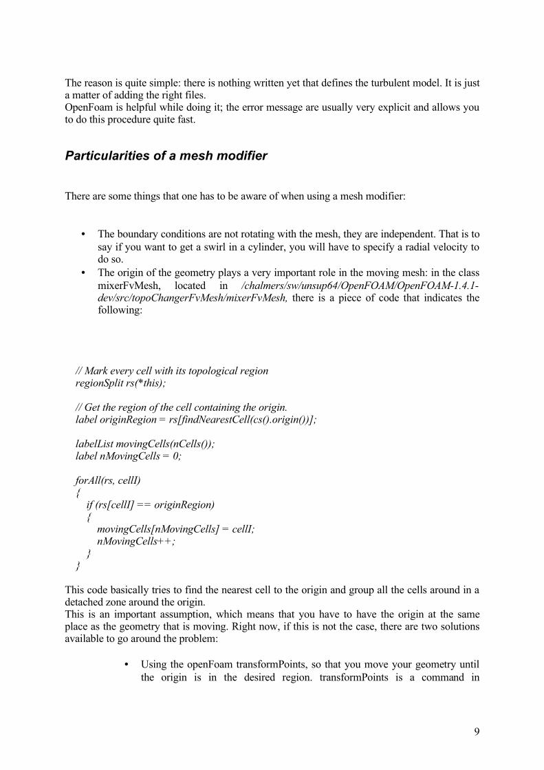
• The origin of the geometry plays a very important role in the moving mesh: in the class mixerFvMesh, located in /chalmers/sw/unsup64/OpenFOAM/OpenFOAM-1.4.1-dev/src/topoChangerFvMesh/mixerFvMesh, there is a piece of code that indicates the following:
// Mark every cell with its topological region regionSplit rs(*this);
// Get the region of the cell containing the origin. label originRegion = rs[findNearestCell(cs().origin())];
labelList movingCells(nCells()); label nMovingCells = 0;
forAll(rs, cellI) { if (rs[cellI] == originRegion) { movingCells[nMovingCells] = cellI; nMovingCells++; } }
This code basically tries to find the nearest cell to the origin and group all the cells around in a detached zone around the origin. This is an important assumption, which means that you have to have the origin at the same place as the geometry that is moving. Right now, if this is not the case, there are two solutions available to go around the problem:
• Using the openFoam transformPoints, so that you move your geometry until the origin is in the desired region. transformPoints is a command in
9

OpenFoam that allows a change in the geometry without having to rewrite the blockMeshDict.It is used the as showed: one has to be careful to be in the run catalog:transformPoints . testCase –translate vectorHowever, despite the easiness of this method it could sometimes be not possible or practical to translate a geometry as desired due to some restrictions.
• Using the dynamicMeshDict, changing the origin in this dictionary. This is as well an easy way to solve this problem.
It is then very important to be aware of this assumption. Before running a sliding interface case, two things are important to check: where is the geometrical origin, and is the sliding interface defined correctly.The sliding interface is as well a big factor in the definition of the moving part: per definition, the slider that is linked to the moving part of the mesh is called inside and the fixed part of the slider is called outside. If one makes a mistake and do the opposite, the wrong part of the mesh will turn.
Figure 4: result of the origin being in the wrong part of the mesh
10

Figure 5: result of writing the wrong slider as inside: the outer part is rotating
Conclusions and remarks about the mesh modifiers
The sliding interface is a part of OpenFoam developed by Hrvoje Jasak in 2005. It is a very important part of OpenFoam development that allows new freedom in computing, especially in turbo machinery. Due to the free access of OpenFoam, this code is being developed and improved almost every month, which makes it strong. When using this part of OpenFoam, it is better to be aware of what is happening on the forum, and do regularly updates on svn.The machinery behind dynamic mesh is very well written and really nicely organized, but there are still some drawbacks that one has to keep in mind. The mesh modifier operates at each time step of a computation, which means that at each time step, OpenFoam looks for faces that have to be detached and attached. The bottom of this is that it is quite heavy, and it can take quite a lot of memory. The other important drawback is that the dynamic mesh is not working in parallel, which limit the computation power when using a big mesh. Parallel computation will come in the coming years, but at the moment the sliding interface is available only on one processor.
11

Multi reference frames, or MRFSimpleFoam
Multi reference frame is a part of OpenFoam developed by OpenCFD. You should then switch in your bashrc file to the OpaenFoam version 1.4.1.The tutorial that will be used to explain MRFSimpleFoam can be found as followed:
cp -r /chalmers/sw/unsup/OpenFOAM/OpenFOAM-1.4.1/tutorials/MRFSimpleFoam/mixerVessel2D/ .
The Multi Reference Frames solver is not compiled in any of the used version of OpenFoam. The source code can be found in /chalmers/sw/unsup/OpenFOAM/OpenFOAM-1.4.1/tutorials/MRFSimpleFoam/.In order to use this code and to compile it, copy it in the run catalogue and use wmake.
cp -r /chalmers/sw/unsup/OpenFOAM/OpenFOAM-1.4.1/tutorials/MRFSimpleFoam/MRFSimpleFoam/ OpenFoam/username-1.4.1/run/cd MRFSimpleFoamwmake
the Multi Reference Frame solver is now available, and one can check which version of OpenFoam is used by doing which MRFSimpleFoam
MixerVessel2D
MixerVessel2D is the same geometry as mixer2D. By digging in the mixerVessel2D one can see the same folder than usual, the zero, constant and system folders.In the constant folder, you will find a dictionary named dynamicMeshDict. This is the same dictionary than the one used in the sliding interface example. This file is here just because mixerVessel2D is a tutorial that has been developed starting from the icoDyMFoam tutorial mixer2D, and dynamicMeshDict has not been deleted as it should have.It is one of the things one has to be careful in OpenFoam: OpenFoam is very helpful due to its open code, and it is quite easy to use a old piece of code and create a new piece that will fit a special case, but it requires attention; some files can be generated by blockMesh or the solver icoDyMFoam or else, and once generated, you will get an error message if trying to run the same solver again. One good way to know whether a file is needed or not is to rename it so that OpenFoam will not recognize it. This way, if OpenFoam complains, then the file is needed, and if not, the file comes from somewhere else.
In the mixerVEssel2D case, dynamicMeshDic comes from mixer2D and is definitely not needed, so one can do cd constantmv dynamicMeshDict dynamicMeshDictIcoDYMFoam
Launching mixerVessel2D
12
MRFSimpleFoam is a solver derived from SimpleFoam, so it is an incompressible turbulent model.Its purpose is to define one or more frames that will be attributed to different parts of the geometry (defined as patches). In the case of the mixerVessel2D, which has the same geometry as the mixer2D, there are two different parts: one is rotating, and is called patch rotor in the MRFSimpleFoam case, and one is non rotating, called stator. When computing, the mesh will then not move, and we will spare the time and memory used in the sliding interface to re-calculate the new position of the mesh. Instead, in MRFSimpleFoam, the different equations will be calculated in two different frames, Cartesian and cylindrical.
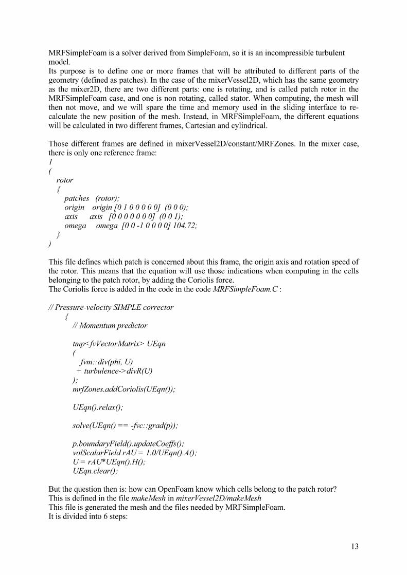
Those different frames are defined in mixerVessel2D/constant/MRFZones. In the mixer case, there is only one reference frame:1( rotor { patches (rotor); origin origin [0 1 0 0 0 0 0] (0 0 0); axis axis [0 0 0 0 0 0 0] (0 0 1); omega omega [0 0 -1 0 0 0 0] 104.72; })
This file defines which patch is concerned about this frame, the origin axis and rotation speed of the rotor. This means that the equation will use those indications when computing in the cells belonging to the patch rotor, by adding the Coriolis force.The Coriolis force is added in the code in the code MRFSimpleFoam.C :
// Pressure-velocity SIMPLE corrector { // Momentum predictor
tmp<fvVectorMatrix> UEqn ( fvm::div(phi, U) + turbulence->divR(U) ); mrfZones.addCoriolis(UEqn());
UEqn().relax();
solve(UEqn() == -fvc::grad(p));
p.boundaryField().updateCoeffs(); volScalarField rAU = 1.0/UEqn().A(); U = rAU*UEqn().H(); UEqn.clear();
But the question then is: how can OpenFoam know which cells belong to the patch rotor?This is defined in the file makeMesh in mixerVessel2D/makeMeshThis file is generated the mesh and the files needed by MRFSimpleFoam.It is divided into 6 steps:
13
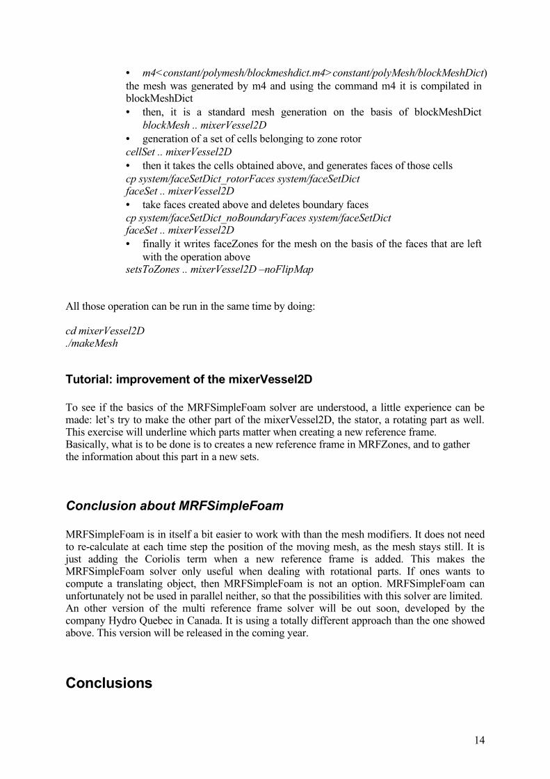
• m4<constant/polymesh/blockmeshdict.m4>constant/polyMesh/blockMeshDict) the mesh was generated by m4 and using the command m4 it is compilated in blockMeshDict• then, it is a standard mesh generation on the basis of blockMeshDict
blockMesh .. mixerVessel2D• generation of a set of cells belonging to zone rotorcellSet .. mixerVessel2D• then it takes the cells obtained above, and generates faces of those cellscp system/faceSetDict_rotorFaces system/faceSetDictfaceSet .. mixerVessel2D• take faces created above and deletes boundary facescp system/faceSetDict_noBoundaryFaces system/faceSetDictfaceSet .. mixerVessel2D• finally it writes faceZones for the mesh on the basis of the faces that are left
with the operation abovesetsToZones .. mixerVessel2D –noFlipMap
All those operation can be run in the same time by doing:
cd mixerVessel2D./makeMesh
Tutorial: improvement of the mixerVessel2D
To see if the basics of the MRFSimpleFoam solver are understood, a little experience can be made: let’s try to make the other part of the mixerVessel2D, the stator, a rotating part as well. This exercise will underline which parts matter when creating a new reference frame. Basically, what is to be done is to creates a new reference frame in MRFZones, and to gather the information about this part in a new sets.
Conclusion about MRFSimpleFoam
MRFSimpleFoam is in itself a bit easier to work with than the mesh modifiers. It does not need to re-calculate at each time step the position of the moving mesh, as the mesh stays still. It is just adding the Coriolis term when a new reference frame is added. This makes the MRFSimpleFoam solver only useful when dealing with rotational parts. If ones wants to compute a translating object, then MRFSimpleFoam is not an option. MRFSimpleFoam can unfortunately not be used in parallel neither, so that the possibilities with this solver are limited.An other version of the multi reference frame solver will be out soon, developed by the company Hydro Quebec in Canada. It is using a totally different approach than the one showed above. This version will be released in the coming year.
Conclusions
14

Two different ways to deal with rotating parts have been shown above. Using those two solvers requires a little knowledge in C++, and some time is needed in order to grasp the methodology of both solvers. But once this time has been invested, the mesh modifiers and the multi reference frames solvers show a very wide panel of possibilities. However, being unable to use those solvers in parallel is an important drawback, and those solvers can not be used for big meshes.
Hydro-Quebec, represented by Martin Beaudoin, in collaboration with Håkan Nilsson in Chalmers are working right now on a new interface, called the GGI ,General Grid Interface. This interface is very promising as it does not re-position the mesh at each time step. One of the goals as well is to make it work in parallel. A functional version of it will be presented in the OpenFoam conference in july in Milano.The release of this new interface should occur in the following year.
References
1. http://openfoamwiki.net/, and more accurately http://openfoamwiki.net/index.php/HowTo_setting_up_dynamic_mesh_cases
2. http://foam.sourceforge.net/doc/Doxygen/html /
3. http://openfoam.cfd-online.com/cgi-bin/forum/discus.cgi
15