open-web steel framing wood roofs
TRANSCRIPT

OPEN-WEB STEEL FRAMING
FOR WOOD ROOFS
V. 1.00

NOTICE Vulcraft, a Division of Nucor Corporation, has provided this catalog for use by engineers and architects in designing and utilizing Vulcraft open web steel joists and joist girders in panelized hybrid wood/steel roof systems. This brochure is for general information only. Vulcraft reserves the right to change, revise or withdraw any Products or procedures without notice.
The information presented in this catalog has been prepared in accordance with recognized engineering principles and is for general information only. While it is believed to be accurate, this information should not be used or relied upon for any specific application without competent professional examination and verification of its accuracy, suitability and applicability by an engineer, architect or other licensed professional. Vulcraft is a manufacturer of open web steel joists, joist girders, floor deck and roof deck. Vulcraft employs a staff of engineers for the design, manufacture and marketing of its products. Vulcraft does not accept the responsibility as the design professional of record for any structure. Vulcraft accepts the delegation of the engineering responsibility only for the products it manufactures, provided the application and applicable loading for these products are specified by the design professional of record. Vulcraft provides engineering for the design of its products and does not displace the need on any project for a design professional of record. Publication of the material herein is not intended as a representation or warranty on the part of Nucor Corporation, or of any other person named herein, that this information is suitable for any general or particular use or of freedom from infringement of any patent or patents. Anyone making use of this information assumes all liability arising from such use.

OPEN WEB STEEL JOIST AND JOIST GIRDER PANELIZED ROOF SYSTEM
INTRODUCTION Vulcraft, a Division of Nucor Corporation, has published this brochure to aid designers and contractors in the use of our products. This literature contains the current standards and details utilizing the economy of the Vulcraft open web steel joists and joist girders in the panelized wood roof applications. This brochure is for general information only. It should not be used or relied upon for any specific applications without exercising competent independent professional examination and verification of its accuracy, suitability and applicability by an engineer, architect or other licensed professional of record (referred to hereafter as design professional). Anyone using this information assumes all liability associated with its use. It is the responsibility of the design professional to determine and clearly specify on the contract documents the structural requirements for the Vulcraft products. Please note that Vulcraft only supplies a product to meet the specified requirements on the contract documents and does not determine, analyze or verify those or any other additional structural requirements. For general information concerning Vulcraft products in a Panelized Roof Systems please contact the nearest Vulcraft District Sales Office and we will assist you.
Vulcraft is a member of the Steel Joist Institute (SJI) and the Structural Roof Erectors Association (SREA). All open web steel joists and joist girders are designed and manufactured in accordance to the SJI specifications. Also, the Vulcraft Brigham City, Utah plant is a recognized fabricator of structural steel building components by the International Accreditation Service, Inc., formerly ICBO-ES (Report No. FA-346).

THE PANELIZED ROOF SYSTEM The "Panelized Hybrid Wood/Steel Roof System" joins open web steel joists and joist girders with APA Rated Sheathing. In so doing, it utilizes the economy and strength of open web steel joists and joist girders and the low insulation costs, high diaphragm capacities and unique erection method of the panelized wood roof. The details and information contained in this booklet relate directly to open web steel joists and joist girders in a panelized roof system. Those familiar with traditional open web steel joist and joist girder framing systems must examine the information in this publication closely. There are many differences between those applications and the panelized roof system.
To ensure the successful completion of a project all groups involved must be experienced and knowledgeable in the requirements and procedures of this framing system. Vulcraft recommends using one of the Structural Roof Erectors Association (SREA) Members to erect this type of system. Contact SREA (http://www.srea.org/) if you need a list of these Erectors.
ERECTION The erection procedure is critical to this system. A "panelized roof system" is one where the sub-purlins, erection stability braces and roof decking are connected to the joist with its pre-attached wood nailer while all are on the ground. The entire unit (joist, nailer, sub-purlin, erection stability braces and deck) is then lifted into its proper place on the roof. The free edge of the decking is positioned and nailed to the previously placed joist and the ends of the joist are attached to the support. This is done before any load is applied to the joist and before the next joist is placed. At no time is anyone permitted to walk on a steel joist or unsecured panelized joist assembly. The roof erector is responsible for the proper and safe handling and erection of Vulcraft products and compliance with specific erection requirements.
OPEN WEB STEEL JOISTS AND JOIST GIRDERS When specifying Vulcraft products, the joist type, depth, all loading (including self- weight of the members) and serviceability requirements for each member must be indicated on the contract documents submitted to Vulcraft. The Vulcraft Steel Joists and Joist Girders catalog contains information about Vulcraft products. The Economical Joist Guide, found near the back of the Vulcraft Steel Joists and Joist Girders catalog, may assist the design professional in determining and selecting the most economical Vulcraft joists and joist girders with relation to length, depth, load carrying capacity and self weight. Please examine the general information to become familiar with the detailing standards and requirements of this framing system.
APA Rated Sheathing is used as the roof deck in this framing system. When laying out the Vulcraft products the space between the joists should accommodate the long dimension of the sheet. Remember an additional space of 1/8" is recommended at all panel ends and edge joints.
Since most, if not all of the joists and joist girders on these projects must resist top chord axial loads in conjunction with the lateral load resisting system, these loads must be determined and clearly noted by the design professional on the contract documents. An example of a Joist and Joist Girder Design Criteria Schedule is provided on Figure 7b. Also provisions must be made and noted to transfer these axial loads in and out of the joists and joist girders.
When the panelized erection technique is followed the panel assembly supports the joist against lateral movement and standard SJI bridging is not used. Due to the lateral stability that the deck provides during erection, the top chord bridging is no longer needed. Typical SJI bottom chord bridging is also not used. In its place an angle brace (JB) is attached to the bottom chord of the joist and the sub-purlin as shown on detail 80. The number and placement of these braces shall be in accordance with SJI Specifications limiting the maximum slenderness ratio of a bottom chord subject to tension only to L/240, and a bottom chord subject to compression to L/200. The joist and joist girder specifying design professional should become familiar and incorporate these requirements in this system as well.
WOOD NAILER AND ATTACHMENT This system requires a "wood nailer" be attached to the top chord of the open web steel joist so that the sub-purlins and decking can be connected by standard nailing techniques. Vulcraft punches holes into the horizontal legs of the angles that comprise the top chord of the joist so

that #14 wood screws can be inserted through the holes to secure the nailer (see detail 59 & detail 60). Vulcraft will install a nailer to the top chord of the joist equivalent in quality to Douglas Fir-Larch with a Specific Gravity equal to or greater than 0.49. These nailers can be either solid sawn lumber or an engineered wood product. The thickness of the nailer is typically equal to 1 ¾" for an engineered wood product (LSL and LVL) or 2 ½" for solid sawn lumber. The nailer width is equal to the top chord width. Generally the length of screw is 2" for the 2 ½" and 1 ¾" min. for the 1 ¾" thick nailers. The specifying design professional must verify that the nailer meets all of the necessary requirements for the project.
When Vulcraft supplies the wood nailer and the connection is not specified, the number of screws to adequately attach the nailer to the joist are calculated according to code recognized National Design Specification (NDS) for Wood Construction (current edition) and the requirements specified on the contract documents submitted to Vulcraft. When Vulcraft does not supply the wood nailer, Vulcraft requires that the connection be supplied by a qualified design professional (see detail 59 & detail 60).
It is imperative that the attachment between the nailer and the joist be closely examined and properly designed so that the joist will function as intended. Vulcraft relies on this connection to laterally support the top chord of the joist and to transfer loads to the joist when the occasion requires. This connection is normally designed for three load cases. In the primary load case, the nailer to joist connection must be sufficient to provide lateral stability to the top chord of the joists. The requirements for this load case are found in SJI specification 5.8(e) for K-Series joists and 104.9(e) for LH-Series joists. In a second load case, the withdrawal capacity of the screws must resist and transfer any net uplift requirements to the joist. In a third load case, the screws must transfer the axial forces for the nailer to the top chord of the joist. This case is in conjunction with the lateral stability of the joist.
APA RATED SHEATHING APA-The Engineered Wood Association (APA) through research and testing develops design and manufacturing specifications and standards for structural sheathing. Not all structural wood panels are manufactured and graded under the strict quality auditing requirements set forth by APA. For this reason roof sheathing should be specified with the APA trademark. This is the best assurance that the sheathing used will meet or exceed the design characteristics published by APA. Good resources for design information on APA Rated Sheathing are the APA Design/Construction Guides, Residential & Commercial (E30) and Diaphragms (L350). These publications along with others can be obtained from APA. For your convenience, Vulcraft has referenced some of the information from E30 and L350 that is pertinent to the "panelized roof system" in this brochure.
Specifiers of these products must become familiar with APA trademarks. In E30 the trademarks and design criteria are explained. As a minimum, when specifying Performance Rated Panels the following should be listed; panel thickness, APA trademark, grade, span-rating and exposure durability classification.
The structural panels are oriented parallel to the supports in this framing system. Table 24 (page 44) in E30 shows the allowable load carrying capacity of panels oriented in this way. Table 25 also in E30 (page 44) lists allowable design values used to select stiffeners or sub-purlins. Normally the sheathing in the roof structure is used as a diaphragm to resist and transfer lateral loads. The L350 publication explains methods and requirements for diaphragms. If diaphragm forces are larger than those in this table, consult Table A-1 (page 28) in L350 for high-load diaphragm design values.
Another thing to keep in mind when using this system is the need for temporary expansion joints. If panels are exposed to moisture or humidity during the construction period they tend to absorb moisture and expand. This can develop into a problem depending on the size of the building. Refer to APA Technical Note #U425, Temporary Expansion Joints for Large Buildings for information on this subject.
For literature or technical assistance regarding structural panels, contact APA - The Engineered Wood Association headquarters or the local APA representative (http://www.apawood.org/).

GENERAL INFORMATION
Detailing Standards
* See Table 7b - Recommended Maximum Lateral Seismic Load for transfer through joist/girder seats.
Please consult with Vulcraft before using pitched joists, joists at slopes greater than ½" per foot, bearing seat depths different than shown or joists with other special conditions.
Materials Supplied by Vulcraft
Vulcraft supplies open web steel joist and joist girders with the following:
1. Joist to Joist Girder bolts. 2. Joist bottom chord braces "JB’s" & bolts for their attachment to the joist (See Detail 80). 3. Joist Girder bottom chord braces "UB’s" & bolts when required (See detail 81). 4. A Vulcraft attached 1 ¾" or 2 ½" wood nailer attached with #14 wood screws. The screw spacing is
determined for the joist to nailer attachment requirements.
Materials Not Supplied by Vulcraft (NBV)
Vulcraft does not supply bolts at columns, nails for hangers, nails for JB’s, loose hangers, nor any other miscellaneous rods, angles, blocking and plates that are not shop attached to the joists or joist girders. Vulcraft doesnot specify screw spacing when wood is not attached by Vulcraft.
Please contact Vulcraft before specifying any conditions outside the limits of this brochure.
Joist Girders Joist Girder Member Depth: 18" MinimumJoist Girder Bearing Seat Depth: 7 ½ " TypicalJoist Girder Bearing Seat Holes: 2-13/16 x 2" slots @ 5" gageJoist Girder Bearing Seat Welds: 2-1/4" x 2" fillet welds or equivalent K-Series Joist Joist Member Depth: 18" MinimumJoist Bearing Seat Depth: * 3" with 2 ½" thick wood nailer 3 ¾" with 1 ¾" thick wood nailerJoist bearing Seat Holes: 2-9/16 x 2" slots @ 3 ¼" gageJoist Bearing Seat Welds: 2-1/8" x 1" fillet welds or equivalent LH-Series Joist Joist Member Depth: 18" MinimumJoist Bearing Seat Depth: * 3" or 3 ¾" TypicalJoist Bearing Seat Holes: 2-13/16" x 2" slots @ 4" gageJoist Bearing Seat Welds: 2-1/4" x 2" fillet welds or equivalent

DESIGN EXAMPLE The following example shows one method for properly designating and showing the loading on joists and joist girders. By following this example, or something similar, the time required and the amount of questions asked during the erection plan detailing and the designing of the joists and joist girders are greatly reduced.
In this example, the joist and joist girder mark numbers are shown on the Roof Framing Plan. "J" indicates a K-Series joist, "T" indicates a LH-Series joist, and "G" indicates a Joist Girder. These mark numbers are defined on the Example Joist and Joist Girder Design Criteria Schedule.
The gravity loading on the joists in this example are given as Total Load/Live Load (TL/LL) in pounds per lineal foot. Joists should be designated either using the load per foot designations or by using SJI Standard Joist designations from the SJI joist tables (i.e. 20K3). In this example, 12 psf was used for the joist dead load (D). The roof live load (Lr) is based on 20 psf reducible. The live load was reduced based on section 1607.11.2 of the International Building Code (Also see section 4.9 of ASCE 7-02). It is the responsibility of the Engineer of Record to determine the reduced live load that is applied to each joist. The joist spacing in the example is 8 ft. Any additional concentrated loads should be shown on the roof framing plan.
In the steel/wood hybrid joist system, typically each joist and joist girder must be designed with an additional top chord axial load from tie forces due to wind (W), Seismic (E), or collector (Em) loads. These loads should be clearly indicated in the joist schedule (figure 7b). These loads are assumed to be applied at the centroid of the top chord. Vulcraft will use the appropriate loading combinations for these loads and the gravity loads in accordance with the local governing building code, typically UBC, IBC or NFPA 5000. It is critical that the joist loading given to Vulcraft as W, E, or Em in order to apply the proper loading combinations. It should also be noted that the 1/3 increase in allowable stress has been eliminated in the IBC and NFPA 5000, though it is still allowed in the 1997 UBC.
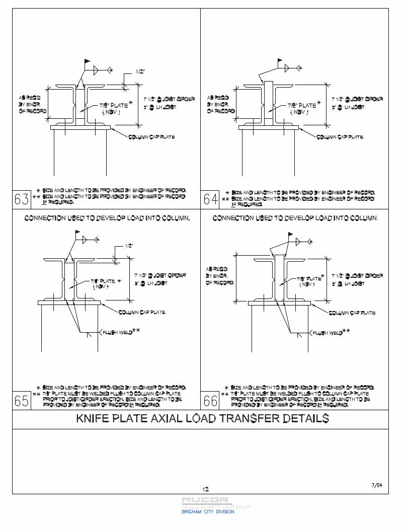
Table 7a shows the recommended maximum additional axial load (W, E or Em) that can be applied to the top chords of joists with varying bearing depths. The bearing depth is determined by the top chord angle size. This table does not include a 1/3 increase in allowable stress. These loads cannot be transferred through the joist bearing seats. An alternate method of transfer should be provided (e.g. tie plate or knife plate). The axial load transfer details 63 through 70 - Axial Load Transfer show these different types of transfer connections. Knife plate connections are not recommended for bearing depths less than 5". It is also recommended that a bearing depth of 5" be used for joists over 70 feet.
Smaller axial loads can be transferred through joist bearing seats. When transferring axial loads through the joist bearing seats, a moment is developed in the end panel due to the distance from the base of the joist bearing seat to the centroid of the top chord.
Typically, the top chord by itself is not adequate to resist the moment developed in the top chord, therefore reinforcement must be provided. Table 7b shows the recommended maximum top chord axial loads that can be transferred through a reinforced seat and the associated seat depth. Reinforcement of the bearing seat and end panel requires additional material and labor cost compared to a standard bearing seat. The type of transfer, whether through a tie plate, knife plate, or through the bearing seat should be noted clearly in the Structural Drawings for the project (See figure 7a and figure 7b).
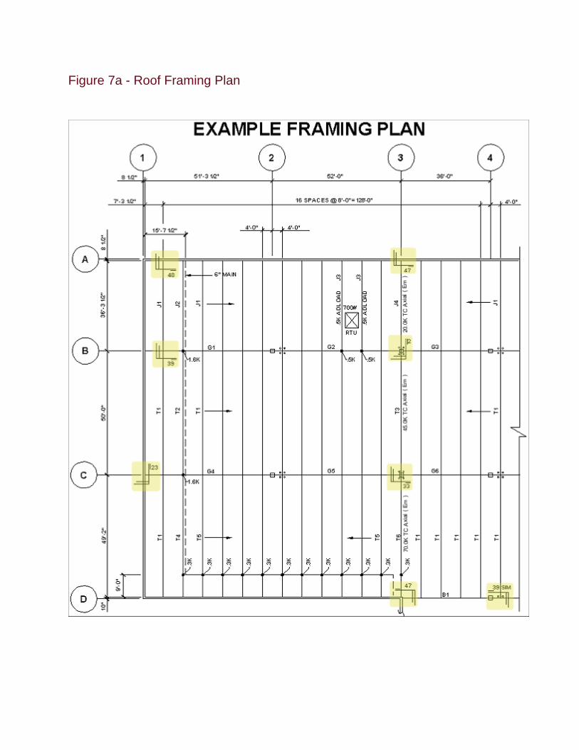
Figure 7a - Roof Framing Plan

AXIA
LD
ESIGN
ATIO
N N
ET WIN
DW
EEm
AXIA
L & M
OM
ENT
MA
RK
TL/LL orU
PLIFTW
IND
WA
LL TIEC
OLLEC
TOR
TRA
NSFER
DETA
ILSA
DLO
AD
REM
AR
KS
SJI D
esignation(PLF)
(KIPS)
(KIPS)
(KIPS)
@ G
RID
S(K
IPS)
(1) & (2)
(3)(4)
(5)(7)
J1 28K
224/12880
W=8.0
E=16.0J2
28K256/128
80W
=8.0E=16.0
32 plf for 6" sprinkler main
J3 28K
224/12880
W=8.0
E=16.00.5
Adload for m
ech. Unit
J4 28K
224/12880
W=8.0
E=16.0Em
=20.0C
ollector (Em) at G
rid 3. 70.0 K at G
rid D reduces to 0 at G
rid A T1
32LH224/128
80W
=8.0E=22.0
T2 32LH
256/12880
W=8.0
E=22.0T3
32LH224/128
80W
=8.0E=22.0
Em=45.0
1.0C
ollector (Em) at G
rid 3. 70.0 K at G
rid D reduces to 0 at G
rid AT4
32LH256/128
80W
=8.0E=22.0
0.3K load for sprinkler m
ainT5
32LH224/128
80W
=8.0E=22.0
0.3K load for sprinkler m
ainT6
32LH224/128
80W
=8.0E=22.0
Em=70.0
0.3K load for sprinkler m
ain
G1
48G7N
8.3K/4.1K
185W
=25E=125.0
125K reduces to 16K
@ G
rid 1G
2 48G
7N8.3K
/4.1K185
W=25
E=125.0G
3 48G
7N8.3K
/4.1K185
W=25
E=125.0G
4 48G
7N11.2K
/6.0K210
W=30
E=125.02.0
125K reduces to 16K
@ G
rid 1; 2.0K A
dload future RTU
(office)G
5 36G
5N9.6K
/4.8K210
W=30
E=125.02.0
2.0K A
dload future RTU
(office)G
6 36G
5N9.6K
/4.8K210
W=30
E=125.0
Building C
ode: 1997UB
CYES
NO
XXXand seism
ic (1997UB
C Section 1612.3.2).
Figure 7b - Joist and Joist Girder D
esign Criteria S
chedule
BR
IGH
AM
CITY
DIV
ISIO
N
(6)#48 @
A, #39 @
B#48 @
A, #39 @
B#48 @
A, #39 @
B#47 @
A, #33 @
B
#39 @ B
, C#39 @
B, C
#39 @ B
, C#39 @
C, #48 @
D#39 @
C, #48 @
D#33 @
C, #47 @
D
#23 @ 1, #2 @
2#2 @
2, 3#2 @
3, 4#23 @
1, #2 @ 2
#2 @ 2, 3
#2 @ 3, 4
A 1/3 increase in allow
able stresses for all combinations including w
ind
(1) When Total Load / Live Load D
esignations are used:a. D
esignations should include "Total Load / Live Load" for Joists (plf) and Girders (kips).
b. Cam
ber is per SJI Standard Specifications unless specifically noted otherwise.
c. Deflection ( i.e. Span/360, Span/240) shall be specified.
d. A Load D
iagram m
ay be required to convey complex loading criteria.
(2) When Standard SJI Joist D
esignations are used: a. Loads, C
amber and D
eflection are per SJI Load Tables and Standard Specifications.b. D
ead Loads are required for Load Com
binations with W
ind or Seismic.
(3) All U
plift Loads shall be shown as N
ET UPLIFT w
hen applicable.(4) W
all tie axial loads shall be UN
FAC
TOR
ED and show
n as "E" only. (DO
NO
T Specify Eh, Ev, Seismic Force A
mplification Factor, R
eliability/Redundancy Factor)
(5) Collector Elem
ent axial loads Em are given for 1997U
BC
Section 1612.4 (2000IBC
Section 1605.4) load combining. See 1997U
BC
Section 1633.2.6
professional, they require special consideration by the manufacturer.
(2000IBC
Sections 1617.1.2 and 1620.1.6) for allowable stress design.
(6) Connection D
etails defining Axial and M
oment Force transfer for Joists and G
irders shall be shown.
(7) Adload is defined as an A
dditional Concentrated D
ead Load located at any panel point.(8) The m
agnitude and location of additional concentrated loads shall be shown on the structural draw
ings when, in the opinion of the specifying
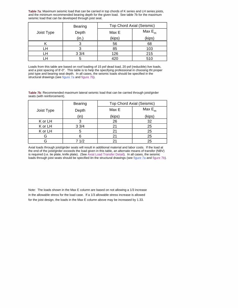
Table 7a: Maximum seismic load that can be carried in top chords of K series and LH series joists, and the minimum recommended bearing depth for the given load. See table 7b for the maximum seismic load that can be developed through joist seat.
Bearing Top Chord Axial (Seismic)
Joist Type Depth Max E Max Em
(in.) (kips) (kips)K 3 56 68
LH 3 85 103LH 3 3/4 126 215LH 5 420 510
Loads from this table are based on roof loading of 15 psf dead load, 20 psf (reducible) live loads, and a joist spacing of 8'-0". This table is to help the specifying professional in choosing tht proper joist type and bearing seat depth. In all cases, the seismic loads should be specified in the structural drawings (see figure 7a and figure 7b).
Table 7b: Recommended maximum lateral seismic load that can be carried through joist/girder seats (with reinforcement).
Bearing Top Chord Axial (Seismic)
Joist Type Depth Max E Max Em
(in) (kips) (kips)K or LH 3 26 32K or LH 3 3/4 21 25K or LH 5 21 25
G 6 21 25G 7 1/2 21 25
Axial loads through joist/girder seats will result in additional material and labor costs. If the load at the end of the joist/girder exceeds the load given in this table, an alternate means of transfer (NBV) is required (i.e. tie plate, knife plate). (See Axial Load Transfer Detail). In all cases, the seismic loads through joist seats should be specified itn the structural drawings (see figure 7a and figure 7b).
Note: The loads shown in the Max E column are based on not allowing a 1/3 increasein the allowable stress for the load case. If a 1/3 allowable stress increase is allowedfor the joist design, the loads in the Max E column above may be increased by 1.33.

VULCRAFT DETAILS
Sheet # Title Details
1 Girder to Tube Column Details 1-4
2,3 Girder to Wide Flange Column Details 7-15
4 Girder to End Bay Column Details 17-20
5 Girder to Panel/Wall Details 23-26
6 Field Installed Girder Nailer Attachment 29-30
7 Joist at Column Details 33-36
8 Joist at Girder Details 39-42
9,10 Joist at Steel Ledger Details 45-54
11 Joist at Top of Wall & Nailer to Joist Attachment 57-60
12,13 Axial Load Transfer Details 63-70
14 Miscellaneous Details 80-82