open systems interconnection (osi) - semantic scholar 101 application layer presentation layer...
TRANSCRIPT

Towards an Abstraction
Hierarchy for CAETI
Architectures, and Possible
Applications.
David Luckham, James Vera, Frank Belz (TRW)Program Analysis and Veri�cation Group
Computer Systems LabStanford University
and TRW �
June 5, 1997
Abstract
This document proposes a four level abstraction hierarchy for CAETI systems architec-
tures for review and discussion by the CAETI community. Some possible applications
are described brie y.
1 Introduction
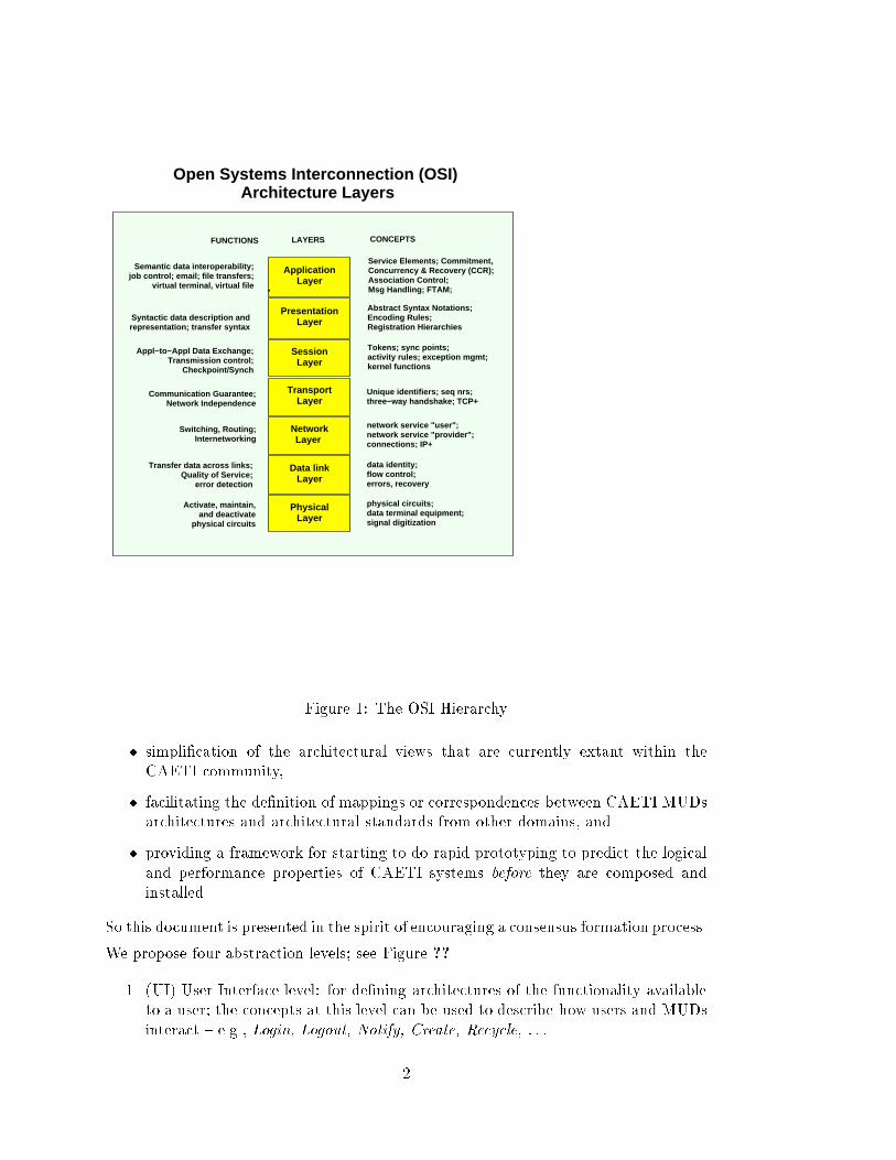
It has become customary to describe families of systems at distinct levels of abstraction.
For example, levels of computer hardware generally include (i) instruction set level, (ii)
register level, and (iii) gate level; there may be other levels too. Another example is
the standard seven level hierarchy of the ISO OSI inter-connection reference model for
network-based systems [?]. This is illustrated in Figure ??.
At each abstraction level, speci�c concepts and components are introduced for de�ning
architectures at that level. At each level, a particular system will have a speci�c
architecture. Di�erent systems obviously have di�erent architectures at some levels.
This paper proposes a four level hierarchy for CAETI MUDS architectures. We em-
phasize that this is a proposal towards the adoption by the CAETI community of
a standard hierarchy. There are several advantages to adopting some such standard
hierarchy, including for example,
�This project is funded by the CAETI program of DARPA under NCCOSC RDTE contract no.
N66001-95-C-8609
1
Module 101
ApplicationLayer
PresentationLayer
SessionLayer
Open Systems Interconnection (OSI) Architecture Layers
Data linkLayer
TransportLayer
NetworkLayer
PhysicalLayer
Abstract Syntax Notations;Encoding Rules; Registration Hierarchies
Activate, maintain,and deactivate
physical circuits
Transfer data across links;Quality of Service;
error detection
Communication Guarantee;Network Independence
Appl−to−Appl Data Exchange;Transmission control;
Checkpoint/Synch
Syntactic data description andrepresentation; transfer syntax
Semantic data interoperability;job control; email; file transfers;
virtual terminal, virtual file
Switching, Routing;Internetworking
LAYERSFUNCTIONS CONCEPTS
physical circuits;data terminal equipment;signal digitization
data identity;flow control;errors, recovery
network service "user";network service "provider";connections; IP+
Unique identifiers; seq nrs;three−way handshake; TCP+
Tokens; sync points; activity rules; exception mgmt;kernel functions
Service Elements; Commitment,Concurrency & Recovery (CCR);Association Control;Msg Handling; FTAM;
Figure 1: The OSI Hierarchy
� simpli�cation of the architectural views that are currently extant within the
CAETI community,
� facilitating the de�nition of mappings or correspondences between CAETI MUDs
architectures and architectural standards from other domains, and
� providing a framework for starting to do rapid prototyping to predict the logical
and performance properties of CAETI systems before they are composed and
installed.
So this document is presented in the spirit of encouraging a consensus formation process.
We propose four abstraction levels; see Figure ??.
1. (UI) User Interface level: for de�ning architectures of the functionality available
to a user; the concepts at this level can be used to describe how users and MUDs
interact { e.g., Login, Logout, Notify, Create, Recycle, : : : .
2

Module 101
UserInterface
Layer
Concepts ofOperations
Layer
AbstractImplementation
Layer
Our Initial Proposed Hierarchy for CAETI Architectures
ResourceLayer
Objects; Verbs; Actions; Agents;"Create object", "Performobject’s verb", "Move object"
Architecural elements of CAETIMUD software implementations
MUD description in terms ofMUD operations
Functionality available to user;interaction among users, MUDs
LAYERSFUNCTIONS CONCEPTS
Workstations, networks, routers,servers, equipment closets, ...
Schedulers, interpreters, databases, event managers
User; MUD; "Login", "Logout", "Notify", "Create","Recycle"
Architecture of hardwareresources available at
DODEA sites
Figure 2: Our Proposed CAETI Hierarchy
2. (ConOps) Concept of Operations Level: for de�ning architectures explaining the
state of a MUD in terms of concepts normally used to \talk about" or discuss
what is happening in a MUD { e.g., Create an object, Perform a Verb of an
object, Move an Object, : : : .
3. (AIL) Abstract Implementation Level: for de�ning architectures of MUDS sched-
3

ulers, interpreters, databases, etc.
4. (RL) Resource Level: for de�ning architectures of workstations, networks, servers
and other resources generally avialable at a highschool.
First, we emphasize that we are proposing a conceptual hierachy, not particular stan-
dard architectures. Within each level, many di�erent architectures are possible. For
example, Mike Smith's \MOO Events" proposal [?] might well be viewed as a pro-
posed formal de�nition of the User Interface level. It de�nes the facilities whereby
agents can communicate with a MOO and conversely. Again, Bob Balzer's categoriza-
tion of CAETI architecture concepts, [?], can be viewed as crossing both the UI and
AIL levels.
Secondly, given the current state of de�nition of this hierarchy, the levels will be viewed
by many as \blurred". But, in this regard, a careful distinction should be made be-
tween an abstraction hierarchy being useful and the possibility that some architectures
can \confuse" abstraction levels. A hierarchy is useful if it clearly can classify some
architectures, can be used to guide architectural design, and to develop principles for
relating architectures at di�erent levels. There is little doubt that some architectures
will confuse levels of abstraction. And, moreover, it is quite likely that one person's
ConOps architecture might well be viewed by someone else as so detailed as to be an
AIL level architecture. At the moment there is no guarantee that a particular archi-
tecture will be viewed by everyone as being at the same abstraction level. Some may,
for example, view Mike Smith's \MOOs events" as being a ConOps level architecture.
In the following sections we sketch possible architectures at each of the other levels. This
is done in the spirit of exemplifying our abstraction levels and promoting discussion.
The main questions are:
3What are conceptual levels of MUDS architecture hierarchies that the
community can agree to adopt?
3 What are the appropriate concepts and components for any particular
level?
2 Architectures for MUDS
Here we allocate a few words to the general issues,
� \What is an architecture?",� \How are architectures de�ned?"
2.1 Interface Connection Architectures
The concept of architecture we feel is most appropriate for most levels of CAETI
systems architecture is the interface connection architecture, so called because all com-
munication between modules is explicitly de�ned by connections between interfaces |
4

Student 1
student 2
Student 3
AstronomyExperiment
MUD
CAETI User Interface Level(Mike Smith Interface)
System Architecture
Figure 3: A User Interface Level architecture
no longer are connections buried in the modules, as in C++ programs for example, but
instead they are de�ned between the features in interfaces. Figure ?? shows this kind
of architecture.
An interface connection architecture can be de�ned before the modules of the system
are built. It can be used as a plan or early prototype of the system. To de�ne in-
terface connection architectures requires more sophisticated interfaces than are found
in programming languages, and a completely new concept to de�ne connections be-
tween interfaces. Rapide provides new features for representing interface connection
architecture, not normally found in programming languages or middleware IDLs. In
summary, the architecture features are:
� interfaces that specify both the features a module provides and, in addition, the
features it requires from other modules. Moreover, there are two kinds of features,
those implying synchronization (i.e., functions) and those implying asynchronous
5

communication (i.e., actions). Rapide interfaces are more complex than, say,
package speci�cations in Ada or classes in C++ which do not specify features
required from other objects.
� behaviors in interfaces: Behaviors are sets of reactive rules that de�ne abstract,
executable speci�cations of the behavior that is required of modules in order to
conform to that interface.
� connections between interfaces de�ne relationships between the required features
of interfaces and the provided features of the interfaces. The simplest kind of
connection is identi�cation between a required feature and a provided feature. 1
Identi�cation connections have the e�ect that whenever a required feature is used
then the connection invokes the provided feature in its place. More general kinds
of connections allow sets of required features to be connected to sets of provided
features.
Connections are dynamic. A connection can depend upon runtime parameters,
or the sets of features that are connected can vary at runtime, or the interfaces
that are connected can also vary dynamically.
� constraints are declarative statements that restrict the behavior of the interfaces
and connections in an architecture. They can be used to explicitly specify re-
quirements on the behavior of an architecture as a whole, or of its individual
components. Conformance to constraints can be checked at runtime, or, in some
cases, decided by proof methods.
We note that interfaces can contain executable behaviors. Connections are also exe-
cutable in the sense that whenever their required features are invoked, they result in
execution of the provided features that they connect to. Consequently, in Rapide an
interface connection architecture can be executed (or simulated) before modules are
programmed for its interfaces. The semantics of the executable parts of Rapide is, in
short, event generation (below).
2.2 Event-based methods
We believe that MUDS will eventually operate on an event-based paradigm since it
is likely that they will become loosely coupled distributed systems (eventually), and
also that they need to support data gathering and monitoring capabilities (e.g., to
support agents). Actual CAETI systems are being implemented using distributed
webware technologies such as Java and CORBA. Such technology has a natural event-
based paradigm which is currrently being explored (and exploited) by vendors in order
to support monitoring, validation, and security of customer systems built with their
webware products.
We would also argue that MUDS architectures should be de�ned and prototyped using
event-based technologies. The authors support the use of Rapide [?] (language and
toolset) to formally specify and prototype MUDS architectures. But other event-based
1Also called a basic connection.
6

technologies may also be appropriate. Indeed, the Stanford Rapide team has started
to investigate the incorporation of some Rapide technology diredctly into Java and
onto particular CORBA Orbs. This would place an event-based technology and toolset
for architecting and animation directly on top of webware.
3 User Interface Level
A User Interface Level architecture should be simply a de�nition of the facilities avail-
able to a user. In the case of CAETI MUDS one might expect this to consist of
de�nitions of facilities such as Login, Logout, Notify, Create, Recycle, : : : .
Figure ?? shows a UI interface (the small blue box in each interface) as part of each
Student and System interface. The only connections between Students and the system
is through the UI. The UI de�nes what students (and agents generally) can do, and
what the CAETI system must provide to support users. A similar (in abstraction level,
not features) interface architecture is described in the DMSO HLA [?] interface speci-
�cation. It's purpose is to de�ne what features are provided to simulations (and what
simulations are responsible for providing) in order to inter-operate using a standard
Runtime Infrastructure.
The UI level appears to be being addressed by Mike Smith's proposal [?] which in turn
is based upon Bob Balzer's [?] attempt to sort out the concepts associated with MUDs
and MOOS. This is not to suggest that these proposals are complete descriptions of
all UI concepts. For example, concepts to do with protection are missing from [?],
although they are essential to Pueblo-MOO, and PARC's Tic-Toc proposal, and surely,
to any CAETI architecture. So, while more work may be needed on the speci�cs, at
this point we suggest taking [?] as a working paper towards exemplifying the UI level
of CAETI system architectures.
4 Concept of Operations Architectures for a MUD
A ConOps architecture of a MUD de�nes the semantics of objects and verbs in that
MUD. This is to be distinguished from an AIL architecture of MUDs which de�nes how
concepts of operations are realized. However (!), if the ConOps semantics is de�ned in
an executable manner (i.e., an operational semantics, such as an abstract intepreter,
as is common is some formal de�nitions of programming languages, for example), then
a Conops architecture may have the look and feel of an AIL architecture to some.
The Appendix to this report contains a detailed sketch of a possible ConOps architec-
ture in Rapide.
5 Abstract Implementation Level
An abstract implementation level architecture de�nes the essential elements in the
implementation of a CAETI system. In a MUD-based systems, these elements would
7

presumably include the interpreter, the database, and the underlying infrastructure
\engine" that the interpreter directs on the basis of commands from the outside world.
The engine includes the information about the state of the MUD (the \database"),
some capability for managing the computational resources, (a \task manager"), and
where there must be a sharing of those resources over time, a \scheduler" to allocate
them.
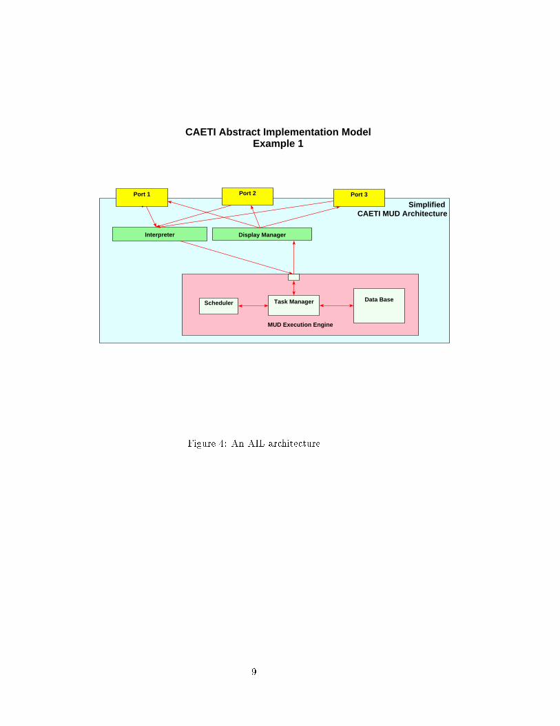
For example, a simpli�ed AIL architecture for a hypothetical MUD might be diagram-
matically represented by Figure ??. In this architecture, all directives from the world
outside the MUD to the MUD's execution engine go throught the Interpreter. Re-
sponses from the MUD to the outside world are mediated by a \Display Manager". A
revised AIL architecture might make access to the functions of the engine directly avail-
able to the world by making the internal interface of the engine \publically available"
to one or more ports as in Figure ??. Thus the external world need not go through the
interpreter to direct the behavior of the MUD.
8
Port 1 Port 2 Port 3
Interpreter
MUD Execution Engine
Scheduler Task Manager Data Base
Display Manager
CAETI Abstract Implementation ModelExample 1
Simplified CAETI MUD Architecture
Figure 4: An AIL architecture
9

Port 1 Port 2 Port 3
Interpreter
MUD Execution Engine
API
Scheduler Task Manager Data Base
Display Manager
CAETI Abstract Implementation ModelExample 2
Simplified CAETI MUD Architecture
Figure 5: A Revised AIL architecture
10
Student 1
student 2
Student 3
Netscape AstronomyExperiment
MUD
CAETI Abstract Implementation Model
System Architecture
Figure 6: An AIL \system" architecture
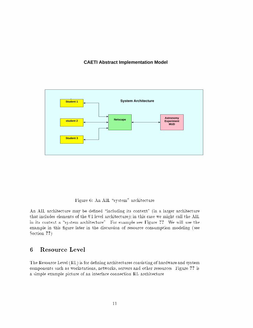
An AIL architecture may be de�ned \including its context" (in a larger architecture
that includes elements of the UI level architecture); in this case we might call the AIL
in its context a \system architecture". For example see Figure ??. We will use the
example in this �gure later in the discussion of resource consumption modeling (see
Section ??).
6 Resource Level
The Resource Level (RL) is for de�ning architectures consisting of hardware and system
components such as workstations, networks, servers and other resources. Figure ?? is
a simple example picture of an interface connection RL architecture.
11

Workstation 1
Workstation 2
Workstation 3
Sparc20
Internet AE MUDServer
NETSERVER
CAETI Resource Model
ResourceArchitecture
Figure 7: A Resource Level architecture
7 Resource Consumption Modelling
We have been experimenting with an approach to resource consumption prototyping
based upon communication between the executable architectures for the AIL and RL
levels of a system, see Figure ??. The objective is to be able to predict the performance
of a given system on a given set of resources. Clearly, one wants to be able to do this
before e�ort is expended in �elding the system.
The crux of our methods depend upon introducing an interface between the two levels
of architecture which allows queries about resource availability and load to be asked by
the AIL and answered by the RL level. When a function in the AIL is to be performed
a query eventmay be communicated to the corresponding components of the RL, where
the \correspondence" is prede�ned by the proposed (by system builders) allocation of
AIL functionality to RL resources.
In Figure ?? the query I/F provides this capability. The connections that use the
query facility are shown in red to distinguish them from the connections of the two
12

Student 1
student 2
Student 3
Netscape AstronomyExperiment
MUD
Query I/FQuery I/F
Workstation 1
Workstation 2
Workstation 3
Sparc20
Internet
Query I/F Query I/F
AE MUDServer
NETSERVER
Query I/F
Query I/F
CAETI Resource Consumption Model
System Architecture
ResourceArchitecture
Figure 8: An AIL architecture mapped to an RL architecture
architectures. Query connections have no e�ect upon the functional properties of the
AIL architecture except to compute timing delays for operations that the AIL archi-
tecture wants to perform. The routing of queries depends upon how the AIL modules
and connections are allocated among the resources. Routing is done by parameters
in queries that indicate which resources are involved in supporting a particular AIL
module function that is making the query.
The advantages of this approach stem from the separation of the AIL and RL architec-
tures. Normal practice in this kind of performance modelling is to put timing estimates
directly into the functions at the AIL. For example, hardware modelling languages such
as VHDL or Verilog include timing delays as modi�ers of assignment operations, to
model how long the computation of the assigned values takes. This \confusion" of AIL
and RL makes it hard to change the RL without risking incorrect changes to the AIL.
Advantages of a separate resource query facility are:
13

� An AIL can be measured on many di�erent RLs because the two architectures
are separate.
� Di�erent allocations of AIL resources can be tried easily on an RL by changing
only the allocation parameters of the queries.
� Changes to the RL architecture and allocation mapping are completely separate
from the functional de�nition of the AIL.
The main disadvantage of the \collaborating architectures" approach is the generation
of large numbers of query events which tends to a�ect the ability of the present Rapide
tools to handle modeling at an appropriate scale. Some preliminary numbers from our
early experiments are given in the next section.
7.1 Preliminary Resource Consumption Modelling Experiments
Using an AIL/RL communicating models scheme involves a multiplier of 8 times the
number of events in the AIL whose resource consumption is to be modelled.
Consider a 4 event transaction in the AIL architecture:
1. Student -> Netscape mouse click to send a question
2. Netscape -> AE MUD ask for answer
3. AE MUD -> Netscape return answer
4. Netscape -> Student answer
Consider the query interaction between the AIL architecture and the RL architecture
in Figure ?? to estimate timing delays. With the very simple query events used in this
model there are two events for each query-answer pair.
Consider the number of events generated inside the RL architecture. We used a very
simple RL architecture in which each shared resource needs some kind of synchroniza-
tion, such as a lock, in resource allocation. This generated three more events: lock
acquire, lock grant, and lock release. This was not the most e�eicnt scheme but due to
the current Rapide implementation limitations, we could not, e.g., use (acquire, grant)
function calls.
Now consider the activities inside the sparc20 station. Since there are two components
in station, each incoming event will invoke at least two more events between NET
server and AE MUD server.
Therefore, the four events in the system architecture will invoke at least
4 events in the AIL architecture
4 * 2 query-answer events in the AIL architecture
4 * 2 query-answer events between the two architectures
4 * 2 query-answer events in the RL architecture
3 lock events in the RL network.
3 lock events in the RL sparc station
14

2 events inside the RL sparc station between NET and MUD servers
Total: 36 events.
So, roughly speaking 32 additional events were required in our models to do resource
consumption modelling for 4 events in the AIL. This \back of the envelope" calculation
does not consider the internal events of the RL (black events) involved in communi-
cation among the resources. However, we expect RL models to consist of statistical
functions that are called in response to time estimation queries. The values of these
functions will vary with the numbers of pending queries for resources. But we expect
that there will not be many internal black events in the RL architecture.
So, a multiplier of 8 may be involved in AIL/RL schemes with simple allocation maps.
This is within the capability scale of the Rapide simulator if the AIL is itself not too
large. The main bottleneck was the Rapide poset browser. But we are implementing a
new generation of Rapide graphical browsing tools to analyze the resulting simulation
for causal issues.
For statistical analysis we have redesigned our simulator interface so simple interfaces
can be programmed to feed the simulation results too spread sheet tools such as Lotus 1-
2-3. We do not expect the multiplier to a�ect analysis involving, e.g., the use of spread
sheets.
8 Correspondence between CAETI MUDs and the ADS
HLA
It has been suggested by some CAETI members, notably Carl Hewitt and David Luck-
ham, that an e�cient MUD might well provide a good RTI (Runtime InfraStructure)
for inter-operating simulations. To do this a MUD would have to be \wrapped" so as
to conform to the HLA interface de�nition [?], [?], [?]. A wrapper for this purpose
should not be di�cult.
To substantiate this hypothesis, a MUDS architecture has to be de�ned at an appro-
priate level of abstraction. That is, not at a level of MUDS semantics (whisper, shout,
move, : : :), but at a level of UI or possibly AIL. We must be able to de�ne MUDS
architecture at a level which a�ords some chance of de�ning a correspondence (possibly
a wrapping, for example) with the DMSO HLA.
References
[1] R Balzer. Caeti architectural concepts. Oct 1995.
[2] International Organization for Standardization. Information processing systems {
Open Systems Interconnection { Speci�cation of Basic Encoding Rules for Abstract
Notation One (ASN.1), December 1987. International Standard 8825.
[3] M.K. Smith. Moo events: Preconditions and postconditions. Jan 1996.
15

[4] Rapide Design team. http://anna.stanford.edu/rapide/rapide.html. Jun 1995.
[5] US Department of Defense Modeling and Simulation O�ce. Department of Defense
High Level Architecture for Simulations, version 0.1, interface speci�cation edition,
July 1995. This and the other de�nition documents, the HLA Object Model Tem-
plate and the HLA Management Plan are available for downloading through the
DMSO homepage (http://www.dmso.mil).
[6] US Department of Defense Modeling and Simulation O�ce. Department of Defense
High Level Architecture for Simulations, version 0.2, interface speci�cation edition,
October 1995. This and the other de�nition documents, the HLA Object Model
Template and the HLA Management Plan are available for downloading through
the DMSO homepage (http://www.dmso.mil).
[7] US Department of Defense Modeling and Simulation O�ce. Department of Defense
High Level Architecture for Simulations, version 0.3, interface speci�cation edition,
January 1996. This and the other de�nition documents, the HLA Object Model
Template and the HLA Management Plan are available for downloading through
the DMSO homepage (http://www.dmso.mil).
16

A Appendix
A CONOPS-Level Rapide Model of CAETI MUD Architecture(s)
A.1 Introduction
This document seeks to capture a description of MUDs in Rapide. It aims to allow a
more formal discussion of the issues involving MUD architecture as well the ability to
execute MUD models.
The model this document describes is based on a writeup by Bob Balzer which was
distributed by Frank Belz in a mail message entitled \CAETI Architecture Concepts
and Design." At this time this paper does not capture all of thore semantics of that
document, but I have not seen anything in that document which I think cannot be
expressed in this framework. Further, I believe this framework may allow us to detect
some issues which are not clear in Dr. Balzer's document. Such questions will be
detailed at the end of this document.
A MUD architecture may be described at several di�erent layers of detail. An analogy
is to think of a typical program. It could readily be described at three di�erent levels:
the user interface level, the process level and the hardware level. The user interface level
is where the interaction the user has with the running program. For many programs,
such as a calculator, that is a at, non-interesting level. MUDs, on the other hand,
have a user interface which is architectually rich: full of rooms and agents. The second
level, the process level, is the architecture of the the running program. It consists of the
data structures of the program and the hierarchical nestings of such structures. The
third level, the hardware level, consists of the actual hardware the running program
is executing on. Modules in such an architecture would represent actual hardware
components. Figure ?? gives a graphical depiction of these levels.
User Interface
Process
Hardware
modules: UI conceptsconnections: UI concepts
modules: Data structuresconnections: function calls, etc.
modules: Hardware componentsconnections: wires, media
Figure 9: Di�erent architecture levels for a program.
In this document we attempt to model the process level architecture of a MUD.
17

A.2 Top Level
The top level description of Balzer's document describes three main kinds of \things":
Rooms, Agents and Objects. In this document we will view each of these things as a
type. Further Rooms and Agents are both subtypes of Objects. There is no subtype
relation between Rooms and Agents.
Object
Room Agent
Figure 10: Subtype Relationship.
Our general strategy will be to de�ne three types Rooms, Agents and Objects. The
di�erent behaviors of actual Objects, Agent and Room instances will be handled by
having the instances contain di�erent data which a�ects their behavior.
Please note that while I will try to use Rapide syntax, I will be liberal in my use of
data syntax. For examples I will ( data, data) to mean a set literal and ( (name, data),
(name, data) ) to mean an array literal [at least until I learn Rapide literal syntax].
Architecturally, Rooms may contain Agents and Objezcts (may they contain other
Rooms?). All [top-level] Rooms are then contained in a new construct, Mud, which
also contains the built-in Base Simulator.
A.3 Object Type
The Object type is the simplest we deal with. It is a parameterized type with each
instance instantiated with the Verbs it understands, its behavior with those verbs and
restrictions on who may execute the verbs.
type Actor_Name is String;
type Verb is String;
18

type MCommand is String;
type MCode is Sequence(MCommand);
type Object(Valid_Verbs : Set(Verb);
Program : Array [Verb] of MCode;
Attributes : Array [String] of Object;
Valid_Actors : Array [Verb] of Set(Actor_Name)) is interface
action in Affect_Object(A: Actor_Name; V : Verb;
Parameters : Sequence(String));
action out Affect_World(target : Object_Name; V : Verb;
Parameters : Sequence(String));
behavior
-- this function executes the MUD code. It is a little state
-- machine which understands the basic MUD operations (performing
-- verbs on objects) and maybe a bit of control flow
function Mcode_Exec(Code : MCode;
A : Actor_Name;
Parameters : Sequence(String)) is
-- little state machine
case Code is
"PAGE" =>
Affect_World(Parameters[1], "Page", Parameters[2..Parameters'End]);
"SAY" =>
Affect_World(Parameters[1], "Say", Parameters[2..Parameters'End]);
"WHISPER" =>
Affect_World(Parameters[1], "Whisper", Parameters[2..Parameters'End]);
end Mcode_Exec;
-- This function determines what do in response to a request from
-- some object to manipulate us
function Handle(A : Actor_Name; V: Verb;
parameters : Sequence(String)) is
-- if verb is not valid, refuse it
if not Valid_Verbs.Is_Member(V) then
Affect_World(A, "Refusal",("Verb not valid"));
-- if actor is not allowed to perform "verb", refuse it
else if not Valid_Actors[V].Is_Member(A) then
Affect_World(A, "Refusal", "Not allowed");
-- otherwise, execute it
else
Mcode_Exec(Program[V],A, parameters);
end Handle;
19

begin
-- turn an incoming event into a function call
(?A : Object_Name, ?V in Verb; ?P in Sequence(String)):
Affect_Object(?A, ?V, ?P) => Handle(?A,?V,?P);;
end Object;
To use this de�nition, we might create an object which can be poked and responds by
trying to slap its poker:
Curly : Object(("poke"), (("poke", ("slap _Actor"))),
("poke", ("ALL")));
Here we de�ned that object Curly knows about one verb: poke. Its response to being
poked it to attempt to poke the thing that poked it (we hoke up some syntax here,
de�ne \ Actor" to be a variable holding the name of the actor we are responding to.
Obviously a small, precisely de�ned syntax could be created without too much e�ort).
An object receives requests via its in action
A.4 Room Type
Continuing, we might de�ne Rooms similarly to Objects. The Balzer discussion em-
phasized that a Room's implementation is de�ned into two parts. A trusted \Base
simulator" and an untrusted \Room simulator". We note that our Object de�nition
above could be viewed the same way. It has a hard coded (trusted) base for handling
unde�ned verbs and invalid actors and then turns control over to the untrusted user
code for the implementation of the objects verbs.
Similarly for Rooms, we will have a function \Handle" which deals with the base
simulator tasks (exiting, notifying agents of events, etc.) and which hands o� other
tasks to be the Room simulator.
type Room is (Room_Simulator : MCode) is
include Object; -- probably illegal since Object is a constructor
-- Function Request_Entry is called to request entry to the room. We
-- make it synchronous since the caller relies on return value.
-- return value semantics:
-- true => entry allowed
-- false => entry denied
function Request_Entry(A : Actor_Name) return Boolean;
-- This is
20

require function Request_Exit(A : Actor_Name; R : Room) return Boolean;
behavior
Exits : array [String] of Room;
-- this function executes the MUD code. It is a little state
-- machine which understands the basic MUD operations (performing
-- verbs on objects) and maybe a bit of control flow
function Mcode_Exec(Code : MCode);
A : Actor_Name;
Parameters : Sequence(String)) return Object is
-- little state machine
end Mcode_Exec;
-- this function handles the predefined aspects of a room
-- i.e., the Base Simulator
function Handle(A : Object_Name; T : Object_Name; V : Verb;
Parameters : Sequence(String)) is
begin
if V == "Exit" then
if Request_Exit(A, Exits[Parameters[1]]) then
Unlink(Dereference(A)); -- Rapide unlink object funciton call
else
Dereference(A).Affect_Object("NULL","Refuse", ("T,V,Parameters"));
end if;
else
...
end Handle;
function Request_Entry(A : Actor_Name) return Boolean is
begin
if Mcode_Exec(Room_Simulator, A, ("Request_Entry")) == True then
Link(Derefernce(A)); -- Rapide Link function call
return True;
else
return False;
end if;
end Request_Entry;
begin
(?O, in Object; ?T in Object_Name; ?V in Verb; ?P in Sequence(String)):
?O.Affect_World(?T,?V,?P) => Handle(?O.Attributes["Name"], ?T, ?V, ?P);;
end Room;
21

So to create a Room which looks like a an Old West Saloon, we would need to crate
the MCode which simulates such a room, and then instantiate a Room instance with
it:
Old_West_Saloon : Room(OWS_MCode);
Note that the Old West Saloon Mcode could be created dynamically at run time (per-
haps by one of the agents) and then the Room could be created. This even though the
Old West Saloon was not know at compile time.
A.5 Agent Type
The Agent Type seems to be just an Object except that instead of executing a piece of
Mcode, the Agent relies upon an external source for its behavior. We will use Rapide's
nascent IO features to provide that functionality.
type Agent(IO : Read_Write_Port) is interface
include Object; -- probably illegal since Object is a constructor
behavior
-- this function executes the MUD code. It is a little state
-- machine which understands the basic MUD operations (performing
-- verbs on objects) and maybe a bit of control flow
function Mcode_Exec(Code : MCode);
A : Actor_Name;
Parameters : Sequence(String)) return Objectis
-- little state machine
end;
-- turn an incoming event into a function call
(?A in Actor_Name; ?V in Verb; ?P in Sequence(String)):
Affect_Object(?A, ?V, ?P) => Put_String(IO,
"Actor ?A was to ?V you with ?P");;
-- assume we get events when data is input
(?S in String):
IO.Get_String(?S) => Mcode_Exec(?S);;
end;
22

A.6 MUD Type
All of our [top level] rooms exist in a MUD architecture. That architecture controls
the inter-room communication and contains one
The MUD system creates agent instances when prompted to by some outside force.
The instance is connected to an input/output device which is told of events impinging
on the agent and which provides events which should be generated by the agent.
type Internet_Access is
action out Create_Link(A : Agent;
end Internet_Access;
architecture MUD is
Internet : Internet_Access;
begin
(?A in Actor_Name; ?R in Room):
Room::Request_Exit(?A, ?R) to ?R.Request_Entry(?A);
end MUD;
A.7 Scenario
This section is intended to give some example of how the information ow occurs in this
setup. Let us assume that we have a Room Pet Store which contains an Agent Boy and
an Object Cat. Further we will assume that the Boy \decides" it wants to pet the Cat.
That decision might be made autonomously if the Boy is an Agent or it might be made
as part of a response to some other stimuli if the Boy is not active. The Boy Object
emits an A�ect World event with parameters (Cat, Pet,()). The Room architecuture
matches that event and process it though the Room's Handle function. That function
decides whether the event is one that is allowed in the Room (among other things).
Assuming the event is allowed, the Room generates an A�ect Object event on the Cat.
The Cat then processes that event in its Handle function and does the appropriate (as
de�ned by the Cat) response. This scenario is illustrated in Figure ??
A.8 Mapping to Mike Smith's model
The events in Mike Smith's model correspond fairly closely to the events in the above
model. We illustrate that by de�ning mappings from patterns of behavior in the above
model to Mike Smith Events
23

Boy Cat
Affect_World(Cat, Pet, ()) Affect_Object(Boy, Pet, ())=>
Pet_Store
Figure 11: Graphical depiction of example scenario.
(?0 in Object; ?V in Verb; ?P in Parameters) ?O.Affect_Object(?A, "Refusal", ?P) =>
REFUSE(?O, ?P[1], ?P[2]);
(?R in Room; ?A in Agent) ?R.Request_Entry'Return(True,?A) =>
MOVE(<unknown>, <unknown>, ?A, ?R);
A.9 Commentary
Please note that much of the functionality is still left unspeci�ed, but hopefully the
path to adding it is clear.
Some questions I have:
1. Can rooms contain rooms
2. Is there anything observable from the outside an object instance which distin-
guishes it from an agent instance (and vice versa)
24

3. Is it possible for an Object to generate an event during the time it is transfering
from one Room to another? Must the system guarantee any consistency rules
(i.e., \any generated event is handled by one and only one Room")
Some comments: Dr. Luckham mentioned that objects might \inherit" from other oth-
ers. We could easily implement this functionality by having an object contain pointer to
another objects and using that contained object's methods when the container wished
to inherit.
25