open metering system technical report 02 wired m … · open metering system technical report 02...
TRANSCRIPT

Open Metering System Technical Report 02
Wired M-Bus
Version 1.0.4 – 2015-10-26 Release

Open Metering System Technical Report 02 – Wired M-Bus Version 1.0.4
OMS GROUP OMS-TR02_Wired_M-Bus_v1.0.4 2/79
Table of contents
1 Preface ............................................................................................................................................................ 7
2 Introduction ...................................................................................................................................................... 8
3 Glossary of terms ............................................................................................................................................ 9
4 References .................................................................................................................................................... 12
5 Decisions and new definitions by OMS AG4 ................................................................................................. 13
5.1 Physical Layer ...................................................................................................................................... 13
5.1.1 Cabling............................................................................................................................................. 13
5.1.2 SC charge/discharge ....................................................................................................................... 15
5.1.3 Inrush current ................................................................................................................................... 15
5.1.4 Rise and fall times ........................................................................................................................... 16
5.1.5 Identification of the unit loads .......................................................................................................... 16
5.1.6 Switch-on process ........................................................................................................................... 16
5.1.7 Upper limit for voltage variation ....................................................................................................... 17
5.1.8 Minimum slave M-Bus voltage ......................................................................................................... 18
5.1.9 Hysteresis voltage deviation ............................................................................................................ 21
5.1.10 Transmission of the remaining communication energy of the battery (optional) .......................... 28
5.1.11 Break detection (mandatory) ....................................................................................................... 28
5.1.12 EMC requirements ...................................................................................................................... 28
5.1.13 Logical slave disconnect (mandatory) ......................................................................................... 28
5.1.14 Overview master characteristics .................................................................................................. 29
5.2 Link layer .............................................................................................................................................. 30
5.2.1 Baud rates (mandatory) ................................................................................................................... 30
5.2.2 Idle time between datagrams ........................................................................................................... 30
5.2.3 Change of primary and secondary addresses, unique secondary address ..................................... 30
5.2.4 Two or more logical M-Buses in one hardware environment ........................................................... 31
5.2.5 Datagram detection ......................................................................................................................... 31
5.2.6 Special primary addresses 254, 255 (mandatory) ........................................................................... 32
5.2.7 SND-NKE (mandatory) .................................................................................................................... 33
5.3 Networking layer / secondary addressing ............................................................................................ 33
5.3.1 Enhanced Selection (mandatory) ..................................................................................................... 33
5.3.2 Determination of addresses in adapters: Rule for incorrectly labelled meter (mandatory) ............... 33
5.4 Application Layer .................................................................................................................................. 35
5.4.1 OMS Vol. 2 chapter 2.2: table with CI-fields (mandatory) ................................................................ 35
5.4.2 New VIF/VIFE for the frame identification for multi datagram RSP_UD (mandatory) ...................... 35
5.4.3 New device type for wired adapters (mandatory) ............................................................................. 35
5.4.4 Rules for multi datagram RSP_UD (mandatory, derived from EN 13757 definitions) ...................... 35
5.4.5 Rules for discarding application errors (mandatory) ........................................................................ 35
5.4.6 Identification of a meter type in the master (mandatory) .................................................................. 35
5.4.7 Minimum communication capabilities for slaves (mandatory) .......................................................... 35
5.4.8 Commands for communication if applicable (mandatory) ................................................................ 36

Open Metering System Technical Report 02 – Wired M-Bus Version 1.0.4
OMS GROUP OMS-TR02_Wired_M-Bus_v1.0.4 3/79
5.4.9 Extension of FDh table .................................................................................................................... 36
5.5 Application Profile ................................................................................................................................ 37
5.6 Installation ............................................................................................................................................ 37
5.7 Certification .......................................................................................................................................... 37
5.7.1 Bit timing .......................................................................................................................................... 37
5.7.2 Startup ............................................................................................................................................. 37
5.7.3 Scope .............................................................................................................................................. 37
5.7.4 Test setup ........................................................................................................................................ 37
5.8 Security ................................................................................................................................................ 37
5.8.1 Introduction ...................................................................................................................................... 37
5.8.2 Unencrypted messages for Wired M-Bus ........................................................................................ 38
5.8.3 Layer structure ................................................................................................................................. 39
5.8.4 AFL mode 5 (Security Profile A) ...................................................................................................... 40
5.8.5 AFL mode 7 (Security Profile B) ...................................................................................................... 41
5.8.6 AFL mode 13 (Security Profile C, TLS) ............................................................................................ 43
6 Cross-reference table for chapters 7 and 5 ................................................................................................... 45
7 Known wired M-Bus issues ............................................................................................................................ 48
7.1 Physical Layer ...................................................................................................................................... 48
7.1.1 Cabling............................................................................................................................................. 48
7.1.2 Connectors ...................................................................................................................................... 48
7.1.3 SC Charge/Discharge ...................................................................................................................... 48
7.1.4 Inrush Current .................................................................................................................................. 48
7.1.5 Rise and fall times ........................................................................................................................... 48
7.1.6 Bit timing .......................................................................................................................................... 48
7.1.7 Number of unit loads > 1 .................................................................................................................. 49
7.1.8 Statement of unit loads for master and slave ................................................................................... 49
7.1.9 M-Bus voltage switch-on process .................................................................................................... 49
7.1.10 Specify upper limit for voltage deviation (due to M-Bus slaves current regulation) ...................... 49
7.1.11 Minimum M-Bus voltage (mark and space) ................................................................................. 49
7.1.12 Hysteresis voltage deviation ........................................................................................................ 49
7.1.13 Inconsistent description of the M-Bus break length (slave collision detect) ................................. 49
7.1.14 M-Bus break: Scope for interpretation concerning the definition of the M-Bus break .................. 50
7.1.15 M-Bus break (I) ............................................................................................................................ 50
7.1.16 M-Bus break (II) ........................................................................................................................... 50
7.1.17 Break detection ........................................................................................................................... 50
7.1.18 Intrinsically safe M-Bus................................................................................................................ 50
7.1.19 Battery-powered devices ............................................................................................................. 50
7.1.20 Problems with special meters: M-Bus converters to 20 mA......................................................... 50
7.1.21 Limitations in the readout frequency (energy meters and water meters generally) ..................... 50
7.1.22 Readout frequency ...................................................................................................................... 51
7.1.23 Behaviour of battery-powered meters ......................................................................................... 51

Open Metering System Technical Report 02 – Wired M-Bus Version 1.0.4
OMS GROUP OMS-TR02_Wired_M-Bus_v1.0.4 4/79
7.1.24 Problems with special meters: Meter xxx in battery operation ..................................................... 51
7.1.25 Contravention of specification: Discrete designs ......................................................................... 51
7.1.26 Contravention of specification: Capacitance too high .................................................................. 51
7.1.27 EMC basic requirements for sockets/casing ................................................................................ 52
7.1.28 Define EMC compliant input wiring for the M-Bus slave .............................................................. 52
7.1.29 Certification of built-in M-Bus ICs ................................................................................................ 52
7.1.30 Topology key questions ............................................................................................................... 52
7.2 Link Layer ............................................................................................................................................ 53
7.2.1 M-Bus timing requirements .............................................................................................................. 53
7.2.2 Idle time between datagrams ........................................................................................................... 53
7.2.3 Faster scanning of M-Bus devices ................................................................................................... 53
7.2.4 Contravention of specification: Incorrect timing ............................................................................... 53
7.2.5 Contravention of specification: Delivery state primary address........................................................ 53
7.2.6 Contravention of specification: Change to the meter address.......................................................... 53
7.2.7 Contravention of specification: Change to the primary address ....................................................... 53
7.2.8 Primary addressing difficulties ......................................................................................................... 53
7.2.9 Two or more logical M-Buses in one hardware environment ........................................................... 54
7.2.10 Detection of datagram end through timeout or interpreter (valid datagram) ................................ 54
7.2.11 A-field: Are special addresses FEh, FFh always to be supported? ............................................. 54
7.2.12 Automatic baud detection: Mandatory / mandatory only for recommended baud rates? ............. 54
7.2.13 Auto baud rate fallback: Mandatory; clarify time window ............................................................. 54
7.2.14 Special single control character A2h: Meaning, specify use? ...................................................... 54
7.2.15 Status request (REQ_SKE) is required; use needs to be more exactly specified........................ 54
7.2.16 SND-NKE .................................................................................................................................... 54
7.2.17 Multiple messages: Identification in link layer .............................................................................. 55
7.2.18 Definition of FCB ......................................................................................................................... 55
7.2.19 Limitation of the permitted baud rates to 300, 2400 and 9600..................................................... 55
7.2.20 Addressing .................................................................................................................................. 55
7.2.21 Primary address .......................................................................................................................... 55
7.2.22 Baud rate ..................................................................................................................................... 55
7.2.23 Specification issue ....................................................................................................................... 55
7.2.24 Definition deficiency: Set primary address................................................................................... 55
7.3 Networking layer / secondary addressing ............................................................................................ 56
7.3.1 REQ-UD2......................................................................................................................................... 56
7.3.2 Secondary address (I) ..................................................................................................................... 56
7.3.3 Secondary address (II) .................................................................................................................... 56
7.3.4 Select is lost (electricity meters generally) ....................................................................................... 56
7.3.5 Contravention of specification: Secondary addressing .................................................................... 56
7.3.6 Secondary addressing mandatory ................................................................................................... 56
7.3.7 Secondary addressing as minimum requirement for M-Bus slaves ................................................. 56
7.3.8 Serial number .................................................................................................................................. 56

Open Metering System Technical Report 02 – Wired M-Bus Version 1.0.4
OMS GROUP OMS-TR02_Wired_M-Bus_v1.0.4 5/79
7.4 Application Layer .................................................................................................................................. 57
7.4.1 DIF/VIF use (electricity meters generally) ........................................................................................ 57
7.4.2 Problems with special meters: Meter zzz ......................................................................................... 57
7.4.3 Contravention of specification: Multi datagran readout .................................................................... 57
7.4.4 Consistent implementation............................................................................................................... 57
7.4.5 Datagram content ............................................................................................................................ 57
7.4.6 Function of VIFE .............................................................................................................................. 57
7.4.7 Missing VIFs .................................................................................................................................... 57
7.4.8 Readout of extended data................................................................................................................ 57
7.4.9 Manufacturer-specific VIFs, as an example: Electricity meters with 3 phases ................................. 58
7.4.10 Month end value / set day values ................................................................................................ 59
7.4.11 Datagrams with dynamic length .................................................................................................. 59
7.4.12 Meters with ambiguous data in the datagram .............................................................................. 59
7.4.13 Time information in datagram ...................................................................................................... 59
7.4.14 Consumption meters with pulse inputs ........................................................................................ 60
7.4.15 Date format 03.05.----: Only for parameter readout; identification of set days not permitted. ...... 60
7.4.16 Problems with special meters: Meter aaa .................................................................................... 60
7.4.17 Battery driven meters .................................................................................................................. 60
7.4.18 Multi-RSP-UD .............................................................................................................................. 60
7.4.19 DIB .............................................................................................................................................. 60
7.4.20 Unique manufacturer device type of every meter should be mandatory in OMS ......................... 60
7.5 Application Profile ................................................................................................................................ 61
7.5.1 Specifications on meter design ........................................................................................................ 61
7.5.2 Configuration of meter devices ........................................................................................................ 61
7.5.3 Meter configuration: Define standard commands ............................................................................ 61
7.5.4 Define communication procedures .................................................................................................. 61
7.5.5 Standard response .......................................................................................................................... 61
7.6 Installation ............................................................................................................................................ 62
7.6.1 S0 meters ........................................................................................................................................ 62
7.6.2 Pt100 ............................................................................................................................................... 62
7.6.3 Topology .......................................................................................................................................... 62
7.6.4 230 V mains ..................................................................................................................................... 62
7.6.5 Documentation ................................................................................................................................. 62
7.6.6 Installation and cabling .................................................................................................................... 62
7.7 Certification .......................................................................................................................................... 63
Specifications for interoperability testing and certification .................................................................... 63
Certification of tested products ............................................................................................................. 63
Set up testing procedures and ask laboratories to perform the testing ................................................ 63
7.8 Security ................................................................................................................................................ 64
7.9 Postponed topics .................................................................................................................................. 65
7.9.1 Machine readable data sheet (EDS) ................................................................................................ 65
Open Metering System Technical Report 02 – Wired M-Bus Version 1.0.4
OMS GROUP OMS-TR02_Wired_M-Bus_v1.0.4 6/79
7.9.2 Internet Website with tested devices, data sheets ........................................................................... 65
7.9.3 Marketing ......................................................................................................................................... 65
7.9.4 Low power modes ............................................................................................................................ 65
7.9.5 Communication over Ethernet ......................................................................................................... 66
7.9.6 Intrinsically safe M-Bus protocol ...................................................................................................... 66
8 Version history ............................................................................................................................................... 67
9 Annex A ......................................................................................................................................................... 72
10 Annex B .................................................................................................................................................... 74
11 Annex C .................................................................................................................................................... 76
-NKE-NKE
Open Metering System Technical Report 02 – Wired M-Bus Version 1.0.4
OMS GROUP OMS-TR02_Wired_M-Bus_v1.0.4 7/79
1 Preface
This document describes the Open Metering System requirements for the Wired M-Bus. The Wired M-Bus is normatively represented in the EN 13757-2 / -3 standard. During application of the said standard, a certain amount of scope for interpretation or design freedom is offered. Among other things, this factor applies to the coding of the data within the application layer. A number of different M-Bus datagrams from different manufacturers therefore exist, with partially identical content. Because of this, problems often arise during the interpretation of datagram data in processing by readout systems or readout programs. The specifications and standardisations in this document should contribute to increase the interoperability of Wired M-Bus products and minimise or solve existing problems.

Open Metering System Technical Report 02 – Wired M-Bus Version 1.0.4
OMS GROUP OMS-TR02_Wired_M-Bus_v1.0.4 8/79
2 Introduction
The Wired M-Bus is a field bus for the capture of consumption data from different media. It was developed in the 1990s by Prof. Dr. Horst Ziegler (University of Paderborn) in cooperation with the Techem and Texas Instruments companies. The Wired M-Bus was initially defined in the standard for heat meters, EN 1434. Later followed an independent standard for the Wired M-Bus and the Wireless M-Bus, EN 13757. The physical layer and the data link layer are defined in part 2 of EN 13757. The application layer is represented in part 3. The Wired M-Bus is designed as a two-wire bus which is inexpensive to implement. The wiring topology requirements are very tolerant. In addition to communication, the power supply to the connected devices can be provided via the Wired M-Bus. In normative terms, many configuration options are allowed at the datagram level to the manufacturer of Wired MBus products. As a consequence, a variety of different datagrams exist, with partially identical contents. This variety leads to incompatibilities, together with increased implementation and maintenance costs for downstream readout systems. With the aid of the OMS system definition, the existing shortcomings, incompatibilities and normative grey areas are eliminated. The objective is to ensure the highest degree of interoperability between all Wired M-Bus products. The intention is not to replace the M-Bus standardbut to supplement or limit those places where too much freedom of interpretation is present. First of all therefore, the terms used are explained (chapter 3) and the references are listed (chapter 4). The known problems in using the Wired M-Bus are then stated and briefly explained (chapter 6). Finally, the scope for interpretation is restricted by specifications and definitions (chapter 7). In addition, further standards and documents are referred to in some chapters.

Open Metering System Technical Report 02 – Wired M-Bus Version 1.0.4
OMS GROUP OMS-TR02_Wired_M-Bus_v1.0.4 9/79
3 Glossary of terms
Additional terms and clarifications for glossary annex of OMS Vol. 1 (see chapter 4 for reference).
Term Description, English Description German
A A A
B B B
C C C
C-Field Control Field containing the FCB and FCV bits and other control information
Das Kontrollfeld enthält die FCB und FCV Bits, sowie weitere Kontrollinformationen
CI-Field Control Information Field, contains the type of command sent (set baud rate, application reset, select slave, etc.)
Kontrollinformationsfeld. Enthält die Art des Befehls (set baud rate, application reset, select slave…)
Collision More than one slave sending at the same time, leading to corrupted data
Mehr als ein Slave senden zur gleichen Zeit Daten, wodurch eine Kollision entsteht
D D D
Deselection Clearing the “selected” status by sending a SND-NKE command or a selection command with a non-matching secondary address
Entfernen des „Selected“ Status durch senden eines SND-NKE Befehls oder eines Selection Befehls mit einer nicht übereinstimmenden Sekundäradresse.
DIB The Data Information Block contains one DIF and zero to ten DIFEs for the length, type and coding of the data – also see VIB
Der Data Information Block enthält ein DIF und null bis zehn DIFE für die Datenlänge, -type und –codierung – siehe auch VIB
DIF Data Information Field – control field – element of the M-Bus datapoint, for the resolution and additional control elements
Data information field – Kontrollfeld – Element des M-Bus-Datenpunktes für die Auflösung und zusätzliche Steuerelemente
DIFE Data Information Field Extension, contains additional information such as tariff or subunit of the device; see: DIF
Erweiterung des Data Information Field. Enthält zum Beispiel den Tarif oder eine Untereinheit; siehe: DIF
DIN German Institute for Standardization Deutsches Institut für Normung
DRH Data Record Header, contains the DIB and VIB information bytes and is followed by the data to be transmitted
Der Data Record Header enthält die DIB und VIB Informations-Bytes gefolgt von den zu übertragenden Daten.
E E E
F F F
FCB Frame Count Bit is a toggling bit, signalling if data blocks are repeated due to an error condition (bit not changed) or in correct order.
Das Frame Count-Bit ist ein Umschalt-Bit welches signalisiert ob Datenblöcke Aufgrund eines Fehlers (Bit wechselt nicht) wiederholt werden
FCV Frame Count Valid bit signals whether the frame count mechanism is active
Das Frame Count Valid-Bit legt fest ob das FCB aktiv ist.
G G G
H H H
I I I
J J J
K K K
L L L

Open Metering System Technical Report 02 – Wired M-Bus Version 1.0.4
OMS GROUP OMS-TR02_Wired_M-Bus_v1.0.4 10/79
M M M
Master Provides the power on the M-Bus. Collects data from the slave devices on the M-Bus.
Stellt die Spannungsversorgung auf dem M-Bus bereit. Datensammler für die Informationen der Slave-Geräte am M-Bus
MDH Manufacturer-specific Data Header, followed by manufacturer-specific data
N N N
O O O
P P P
Q Q Q
R R R
REQ-UD1 The master Requests User Data (class 1) Request the User Data. Anfrage des Masters für Benutzerdaten (class1)
REQ-UD2 The master Requests User Data (class 2) Request the User Data. Anfrage des Masters für Benutzerdaten (class2)
RSP-UD Response with user data Respond User Data. Antwort mit Benutzerdaten
S S S
Slave The slaves (usually meters) are seen from the master as constant current sinks connected to the bus, which signal the master by using two different currents if a mark or space has to be transmitted. Data packets from the master are detected by the slaves because of changed voltage levels
Die Slaves (üblicherweise Messgerät) werden vom Master als Konstant-Stromsenken am Bus angesehen. Die Signale werden vom Master über zwei verschiedene Stromschwelle (Mark / Space) erkannt. Datenpakete des Masters werden vom Slave über unterschiedliche Spannungen erkannt.
Selection The master sends a SND-UD command to the address 253, using the specific meter secondary address to select a slave. From that time, the device can be addressed by address 253 until it is deselected.
Der Master sendet ein SND-UD Befehl zur Adresse 253 unter der Verwendung der spezifischen sekundären Adresse des Zählers. Ab jetzt kann der Zähler über die Adresse 253 erreicht werden, bis eine Deselektion erfolgt.
SND-UD Send User Data to slave Send User Data. Senden von Benutzerdaten zum Slave
SND-NKE The value of the FCB is adjusted in master and slave and the slave is deselected when secondary addressing is used
Die Wertigkeit des FCB wird im Master und Slave angeglichen. Unter Benutzung der Sekundäradressierung wird der Slave deselektiert.
T T T
Topology Structure of the M-Bus network with cable lengths, cable types and number and distribution of slaves
Netzwerktopologie: Struktur des M-Bus-Netzwerks mit Kabellängen, -typen und Anzahl und Verteilung der Slaves
U U U
Unit load Constant load (UL) of 1,5 mA which is drawn from the bus if the slave is in idle mode or transmits a “mark” to the master. One to four ULs are allowed.
Last (UL) von 1,5 mA, welche der Slave im Idle-Mode dem Bus entnimmt wenn der Bus im Ruhezustand ist oder der Slave ein „Mark“ an den Master sendet. Es sind ein bis vier ULs erlaubt.
User
A person who designs, installs or starts up M-Bus installations in the field.
Der Benutzer projektiert, installiert oder betreibt M-Bus-Installationen im Feld.

Open Metering System Technical Report 02 – Wired M-Bus Version 1.0.4
OMS GROUP OMS-TR02_Wired_M-Bus_v1.0.4 11/79
V V V
VIB The Value Information Block contains one VIF and zero to ten VIFEs
Der Value Information Block enthält eine VIF und null bis zehn VIFE um den Messwerten eine Einheit und Multiplikator zuzuweisen.
VIF Value Information Field. Element of the MBus protocol used to define units and scaling factor of a datapoint and additional information.
Das Value Information Field definiert Einheiten
und Skalierungsfaktoren sowie
Zusatzinformationen.
VIFE Value Information Field Extensions. Adds information to the VIF (e.g. m3), such as “per hour” or an error status or actions to be performed (e.g. clear data).
Die Value Information Field Extension fügt zur VIF
(z. B. m3) Zusatzinformationen wie „pro Stunde“
oder einen Fehlerstatus oder Operationen (wie
z. B. Daten löschen) hinzu.
W W W
Wired M-Bus Wired version of M-Bus Drahtgebundene Variante des M-Bus
Wiring parameters
Specific parameters of the cable and connectors (R/m, L/m, C/m)
Parameter für Eigenschaften von Kabeln und Verbindungselementen (R/m, L/m, C/m)
X X X
Y Y Y
Z Z Z

Open Metering System Technical Report 02 – Wired M-Bus Version 1.0.4
OMS GROUP OMS-TR02_Wired_M-Bus_v1.0.4 12/79
4 References
OMS:
OMS Specification Volume 1, General Part, Issue 1.4.0 / 2011-01-31 (insert updated version)
OMS Specification Volume 2, Primary Communication, Issue 3.0.1 / 2011-01-29
OMS Specification Volume 2, Primary Communication, Issue 4.0.2
OMS Conformance Test, Volume 1 General Part, Issue 1.0.1 (change to 3.0.0), Volume 2 PHY (Radio
Parameters), Issue 1.0.0 (change to 3.0.0), Volume 3 Data Link Layer, Issue 1.0.1, Volume 4 Application
layer, Issue 1.0.1 (change to 3.0.0)
Appendix to the OMS Specification, Glossary of Terms, Issue 1.0.1 / 2011-11-04
EN:
EN 13757-2: Communication systems for and remote reading of meters – Part 2: Physical and link layer;
if not more precisely declared: February 2005
EN 13757-3: Communication systems for and remote reading of meters – Part 3: Dedicated application
layer; August 2013 is currently valid; if not more precisely declared: August 2005;
EN 60870-5-2: Telecontrol equipment and systems – Part 5: Transmission Protocols – Part 2: Link
transmission procedures, EN 60870-5-2:1992
DIN:
DIN 43863-5: Identification number for measuring devices applying for all manufacturers
Further set of rules:
M-Bus documentation: “The M-Bus: A Documentation” Rev. 4.8 from www.M-Bus.com
Technical Directive BSI TR-03109-1, Requirements for the interoperability of the communication unit of
an intelligent measuring system, version 1.0

Open Metering System Technical Report 02 – Wired M-Bus Version 1.0.4
OMS GROUP OMS-TR02_Wired_M-Bus_v1.0.4 13/79
5 Decisions and new definitions by OMS AG4
5.1 Physical Layer
The definition / description shall support the user with an application guideline to design and setup M-Bus networks for the required number of M-Bus slaves with respect to topology / wiring parameters and communication speed (alternative: the required readout interval) without applying measurement equipment during setup.
5.1.1 Cabling
The informative annex E in the standard EN13757-2 gives the user some examples of typical M-Bus installations using two different cable types. This chapter shall support the user with a refined application guideline to design and setup M-Bus networks for the required number of M-Bus slaves with respect to topology / wiring parameters and communication speed.
5.1.1.1 Cable Types
The standard refers to a telephone cable and a standard mains cable (cross section 1,5 mm2). The mains cable is
rarely used in real installations because this cable has no shielding and the wires are not twisted. The OMS does not suggest using this cable type in heavy-interference environments due to the missing protection against EMC influences.
The OMS reference cable for the M-Bus is defined as:
- J-Y(St)Y 2 x 2 x 0,8 mm (EN 50441:2012 Cables for indoor residential telecommunication installations, . DIN VDE 0815 Installationskabel und -leitungen für Fernmelde-und Informationsverarbeitungsanlagen)
- N x 2 x 0,8 mm diameter copper (0,5 mm2 cross-section), resistance max. 75 Ohm/km per wire loop, with
N = number of pairs of wires, N=1 is enough) - twisted copper pairs - shielding - operating capacity at 800 Hz max. 100 nF/km - attenuation at 800 Hz max. 1,1 dB/km
Other cables with comparable characteristics can be also used. The following explanations and calculations refer to the OMS reference cable type.
5.1.1.2 Topology
There are some basic physical configurations used for the cable connections between the M-Bus master and the slaves. These topologies are star, line and tree wiring as shown below. In real installations, a combination of these topologies will be used. A ring structure is not possible for M-Bus systems. A termination resistor is not allowed.
Figure 1: Topology variants
Master
Slave 1
Slave 2 Slave 4
Slave 3
Master
Slave 1 Slave 3 Slave 2
Master
Slave 1
Slave 2
Slave 4
Slave 3
Master
Slave 1 Slave 2 Slave 3
Ring
Line
Tree
Star

Open Metering System Technical Report 02 – Wired M-Bus Version 1.0.4
OMS GROUP OMS-TR02_Wired_M-Bus_v1.0.4 14/79
5.1.1.3 Wiring rules
- Keep total cable length as short as possible
- Be mindful of disturbance (EMC) from other electricity cables and installations
- Normally connect just one pair of wires; connecting a second pair would decrease the resistance, but increase the capacity of the cable
- Shielding shall be only connected to the protective earth on the master side and not at any slave.
5.1.1.4 The M-Bus lines shall not be coupled with ground / earth or any other voltage
potential.Maximum length
The maximum possible cable length in an M-Bus system depends on the specific configuration, in particular on the type of master (maximum voltage drop), the cable, the topology, and the number of connected meters (unit loads). There are two limits to be considered:
The capacitive length is the maximum total cable length which can be wired to an M-Bus master. The capacity of the cable and the meters deforms the square wave signals. The capacity restricts the highest possible baud rate (communication speed) as shown here:
9600 Bd: 100 nF -> max. 1 km cable
2400 Bd: 400 nF -> max. 4 km cable
300 Bd: 1000 nF -> max. 10 km cable
The total cable length shall never be exceeded.
The resistive length is the maximum length of one cable connected to the master. The resistors in the master, the cable, and the protection resistors in the slaves cause a voltage drop. Each slave must have a minimum of 24 V DC mark voltage at its M-Bus terminals to work properly. The following examples show some typical situations in worst case topologies (all slaves at the end of the cable) and typical topologies (slaves connected to the cable at equal distances):
Example 1: Master for max. 20 meters with 30 V mark voltage and 50 Ohm internal resistance
- 20 slaves, worst case at the end: max. 3,0 km cable length
- 20 slaves, equally distributed: max. 4,0 km cable length
Example 2: Master for max. 60 meters with 40 V mark voltage and 15 Ohm internal resistance
- 60 slaves, worst case at the end: max. 1,0 km cable length
- 60 slaves, equally distributed: max. 2,5 km cable length
Example 3: Master for max. 250 meters with 42 V mark voltage and 10 Ohm internal resistance
- 60 slaves, worst case at the end: max. 2,0 km cable length
- 60 slaves, equally distributed: max. 4,0 km cable length
- 120 slaves, worst case at the end: max. 0,9 km cable length
- 120 slaves, equally distributed: max. 2,0 km cable length
- 250 slaves, worst case at the end: max. 0,4 km cable length
- 250 slaves, equally distributed: max. 0,9 km cable length
M-Bus repeaters can be used if the resistive or capacitive limits are exceeded.

Open Metering System Technical Report 02 – Wired M-Bus Version 1.0.4
OMS GROUP OMS-TR02_Wired_M-Bus_v1.0.4 15/79
The following table summarizes the suggestions of the EN13757-2:
Table 1: M-Bus applications
Application Max.
distance * Total length
** Cable type
Max. no. of meters
Max. baud rate
Small in-house installation 350 m 1 km 0,5 mm² 250 9600 Bd
Large in-house installation 350 m 4 km 0,5 mm² 250 2400 Bd
Small field installation 1 km 4 km 0,5 mm² 64 2400 Bd
Large field installation 3 km 5 km 1,5 mm2 64 2400 Bd
District 5 km 7 km 1,5 mm2 16 300 Bd
* calculated for the worst case situation with all meters at the end of the cable
** Accumulated length of all cable segments in the network topology.
Chapter 5.1.14 shows measured / calculated characteristics of existing products (level converters, master).
An OMS installation guide is currently in preparation. It provides all relevant aspects for an appropriate installation.
5.1.2 SC charge / discharge
As the master in M-Bus systems are modulating the voltage, the slaves have to detect one threshold voltage for determining between logic high and low state of the bus voltage. Because of possible long term changes of the bus voltages and a wide span of allowed bus voltages, the threshold has to be determined dynamically. This can be done by storing the threshold voltage in a capacitor as reference.
It is recommended to use a fixed charge / discharge current solution for charging this capacitor. Following specifications are based on best practise solutions and follow available slave transceiver devices (e.g. ON Semiconductor, Texas Instruments) with a 100 nF – 330 nF storage capacitor:
Charge: Stored voltage must increase at [25 – 500] V/s
Discharge: Stored voltage must decrease at [0,5 – 15] V/s
Ratio between charge and discharge speeds must be > 30
5.1.3 Inrush current
5.1.3.1 Definition and measurement of inrush current
The inrush current is the current flowing into a slave device within 1 µs after powering the bus to any allowed voltage level and must be <100 mA.
The inrush current is measured during the first 1 µs after powering the bus to voltage level Uspace. It is measured with a shunt resistor (i.e. 1 Ohm) in one M-Bus line or with a fast acting current probe. The power source (M-Bus master or power supply) should have a very low impedance (i.e. <1 Ohm) for appropriate measuring. Voltage rise of the supply should be >100 V/µs. For measuring the inrush current the upper limit of the bus voltage is limited to 42 V.
5.1.3.2 Referenced sources from EN13757-2 for defining the inrush current
According to 4.2.2.6 bus load should be less than 100 mA within 1 min in any case
According to 4.2.2.8 bus load should be at its unit load within 1 ms after any bus voltage change
According to 4.2.2.10 input capacity at the slave terminals must be <= 0,5 nF

Open Metering System Technical Report 02 – Wired M-Bus Version 1.0.4
OMS GROUP OMS-TR02_Wired_M-Bus_v1.0.4 16/79
Annex A schematic implementation with series termination 2x Rs/2
Annex B reference schematic with over-voltage protection V3 and series termination R1-R4
5.1.3.3 Hints and remarks
As there is a long-term limit of 100 mA, it is logical to limit the inrush current to 100 mA.
Inrush current is mainly drawn by the input capacity.
Some measurements show that this 100 mA will be sufficient for current designs. But there are also some slaves which need up to 300 mA. One possible reason is that the over-voltage protection has a significant capacity and series termination (as shown in reference designs) follows that over-voltage protection. If termination is in front of over-voltage protection, it will limit the current load to less than 100 mA.
The measurements also show that the time concerned is about 1 µs. After about 200 ns, most of the current traces return to unit load.
5.1.4 Rise and fall times
The following limits on rise and fall times of the voltage modulation apply:
< 75 V/µs (test condition: no load)
< ½ x bit time (test condition: see 4.3.3.4)
5.1.5 Identification of the unit loads
The number of unit loads must be listed in the data sheet. Additionally it can be printed on the device. For devices that are to be installed in switching cabinets, care must be taken that the identification is applied close to the counter, so that as far as possible it cannot be hidden by a screen.
The identification is done in a total of 4 groups, where the maximum of 4 UL, i.e. a current draw of up to 6 mA, is not exceeded.
Table 2: UL ranges
Current draw of device (I) Identification
I <= 1.5 mA 1 UL
1.5 mA < I <= 3.0 mA 2 UL
3.0 mA < I <= 4.5 mA 3 UL
4.5 mA < I <= 6.0 mA 4 UL
The current draw of 4 UL must not be exceeded.
5.1.6 Switch-on process
M-Bus Master:
Initial startup of the M-Bus Master
tReachingAllowedM-BusMarkVoltageLevel = tPowerup M-Bus Master + tM-Bus Voltage rise time
Resetting the M-Bus voltage after detection of an overload / short circuit of the M-Bus master
tReachingAllowedM-BusMarkVoltageLevel = tM-Bus Voltage rise time
Conditions for the activation of the M-Bus voltage from 0 V ≤ UBus < 12 V until reaching the allowed mark state voltage:
Strictly increasing
Minimum slew rate (t’M-Bus Voltage rise time): 168 V/s
Open Metering System Technical Report 02 – Wired M-Bus Version 1.0.4
OMS GROUP OMS-TR02_Wired_M-Bus_v1.0.4 17/79
Test conditions:
𝑅𝑙𝑜𝑎𝑑 =𝑈𝑀𝐵𝑢𝑠𝑀𝑎𝑠𝑡𝑒𝑟,
𝑛𝑜𝑚𝑖𝑛𝑎𝑙
𝑁 ⋅ 𝑈𝐿
𝐶𝑙𝑜𝑎𝑑 = 1,5 µ𝐹
with Rload || Cload, N=Number of Unit Loads, UL = Unit Load = 1,5 mA
M-Bus slave:
Initial startup of the M-Bus network
tSlave communication ready = tPowerup M-Bus Master + tLinedelay + tSum Slave Capacities + tM-Bus Voltage rise time + tSlave Startup delay
Resetting the M-Bus voltage after detection of an overload / short circuit of the M-Bus master
tSlave communication ready = tM-Bus Voltage rise time + tLinedelay+ tSum Slave Capacities + tSlave Startup delay
Note:
The startup delay of 3 seconds is measured from the time when the M-Bus voltage at slave terminals reaches the voltage level of 24 V.
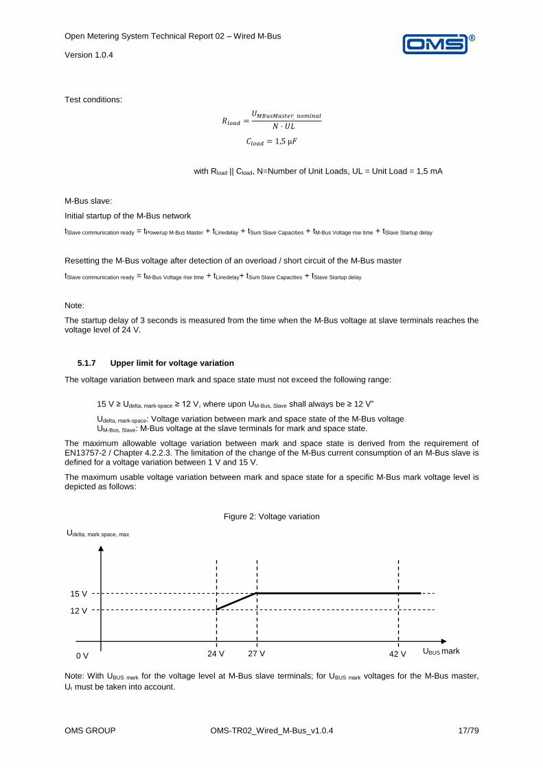
5.1.7 Upper limit for voltage variation
The voltage variation between mark and space state must not exceed the following range:
15 V ≥ Udelta, mark-space ≥ 12 V, where upon UM-Bus, Slave shall always be ≥ 12 V”
Udelta, mark-space: Voltage variation between mark and space state of the M-Bus voltage UM-Bus, Slave: M-Bus voltage at the slave terminals for mark and space state.
The maximum allowable voltage variation between mark and space state is derived from the requirement of EN13757-2 / Chapter 4.2.2.3. The limitation of the change of the M-Bus current consumption of an M-Bus slave is defined for a voltage variation between 1 V and 15 V.
The maximum usable voltage variation between mark and space state for a specific M-Bus mark voltage level is depicted as follows:
Figure 2: Voltage variation
Note: With UBUS mark for the voltage level at M-Bus slave terminals; for UBUS mark voltages for the M-Bus master,
Ur must be taken into account.
Udelta, mark space, max
12 V
24 V 0 V 42 V 27 V
15 V
UBUS mark

Open Metering System Technical Report 02 – Wired M-Bus Version 1.0.4
OMS GROUP OMS-TR02_Wired_M-Bus_v1.0.4 18/79
Referenced sources to define the voltage requirements from EN13757-2:
- EN13757-2 / Chapter 4.3.3.2
USpace < UMark – 12 V, but ≥ 12 V + Ur.
- EN13757-2 / Chapter – 4.3.3.4 Minimum voltage slope
The transition time between space state and mark state voltages from 10% to 90% of the steady state voltages shall be ≤ 1/2 of a nominal bit time. The asymmetry of these transition times shall be ≤ 1/8 of a nominal bit time.
Test conditions (CLoad selected from the E12 value series):
- baud rate 300 Bd: CLoad = 1,5 μF;
- baud rate 2400 Bd: CLoad = 1,2 μF;
- baud rate 9600 Bd: CLoad = 0,82 μF;
- baud rate 38400 Bd: CLoad = 0,39 μF.
- EN13757-2 / Chapter 4.2.2.3 - Variation of the mark state current with bus voltage
For bus voltages in the range (12 V ... 42 V), a voltage variation of 1 V … 15 V shall not change the bus current by more than N × 3 µA/V.
5.1.8 Minimum slave M-Bus voltage
The M-Bus voltage at M-Bus slave terminals shall be at least ±24 V (±21 V) for mark and ±12 V for the space state of the M-Bus voltage.
The slave requirement for a minimum allowable mark state voltage at M-Bus slave terminals is ±21 V (for details, refer to EN13757-2 / Chapter 4.2.1). The M-Bus voltage may fall below the typical mark state voltage of ±24 V (at M-Bus slave terminals) in case another M-Bus slave responds, there is a data collision of two or more M-Bus slaves or at least one M-Bus slave has a fault (for current limitation requirements in case of M-Bus slave faults, refer to EN13757-2 / Chapter 4.2.2.6).

Open Metering System Technical Report 02 – Wired M-Bus Version 1.0.4
OMS GROUP OMS-TR02_Wired_M-Bus_v1.0.4 19/79
The following diagram summarises the requirements from the EN13757-2 concerning the M-Bus voltage for master and slave.
Figure 3: M-Bus voltage
Ur, max = (max. usable bus current)*(max. bus resistance) +
(max. usable bus current)*(max. master source impedance)
> 0; with USPACE-BUS@MBusSlave ≥ 12 V
The following chapters define the voltage requirements according to EN13757-2:2004.
5.1.8.1 Electrical requirements, master
- EN13757-2:2004 / Chapter 4.3.3.1
For currents between 0 … IMax: UMark = (24 V + Ur) … 42 V.
- EN13757-2:2004 / Chapter 4.3.3.2
USpace < UMark - 12 V, but ≥ 12 V + Ur.
- EN13757-2:2004 / Chapter 4.3.1.2 Max. allowable voltage drop (Ur)
The max. voltage drop Ur (> 0 V) is defined as the minimum space state voltage minus 12 V. Ur divided by the maximum segment resistance between the master and any terminal device (meter) gives the maximum useable bus current for a given combination of segment resistance and master.
UBUS
42 V
24 V+Ur
Δ≥-12 V
12 V+Ur 12 V
0 V
SPACE
state
MASTER Send SLAVE Receive
UMARK
UMARK-BUS – 5,7 V Δ≥-8,2 V
21 V
UMARK-BUS
Δ=Ur
MARK
state
Bus
SPACE
state
MA
RK
ra
nge
MA
RK
ra
nge
UMARK-BUS – 8,2 V

Open Metering System Technical Report 02 – Wired M-Bus Version 1.0.4
OMS GROUP OMS-TR02_Wired_M-Bus_v1.0.4 20/79
Electrical requirements, slave:
- EN13757-2 / Chapter 4.2.1 master to slave bus voltages
“…
Voltage range for meeting all specifications: ± (12 V … 42 V).
The bus voltage at the slave terminals in mark (quiescent) state of master - slave communication (= UMark) shall be ± (21 V … 42 V).
The mark voltage shall be stored by a voltage maximum detector with an asymmetric time constant. The discharge time constant shall be greater than 30 × (charge constant) but less than 1 s.
The stored voltage maximum UMark may drop in 50 ms by not more than 0.2 V for all voltages between 12 V and UMark.”
- EN13757-2 / Chapter 4.2.2.11 - Startup delay
In case of a bus voltage drop below 12 V for longer than 0,1 s the recovery time after applying an allowed mark state voltage until reaching full communication capabilities shall be less than 3 s.
The following diagram represents the requirements from EN13757-2:2004 for state recognition and collision detection for the M-Bus slave to M-Bus master communication.
Figure 4: M-Bus states
ΔIMark state, max: maximum allowable variation of the mark state current at the M-Bus master terminals to remain detecting mark state current.
ΔISpace state, min: Threshold where the master detects space state of an M-Bus slave reply.
IBUS
IMax
1..4 x 1,5 mA
0 mA
SPACE
state
MASTER Receive SLAVE Send
ΔImin = 11 mA
IBUS
Bus
SPACE
state
MA
RK
ΔImin – ΔImax =
9 mA
Δ = 41 mA
ΔISpace state,
min = 9 mA
BUS-
collision
ΔIMark state,
max = 6 mA MARK
state
ΔImax =
20 mA
Open Metering System Technical Report 02 – Wired M-Bus Version 1.0.4
OMS GROUP OMS-TR02_Wired_M-Bus_v1.0.4 21/79
The following chapters define the voltage requirements according to EN13757-2:2004.
- EN13757-2:2004 / Chapter 4.2.2.9 – space send current
“The bus current for a slave space state send shall be higher by (11 ... 20) mA than in the mark state for all allowed bus voltages:
ISpace = IMark + (11 ... 20) mA.”
- EN13757-2:2004 / Chapter 4.3.3.7 - Data detection current (reception of slave current pulses)
“Bus current ≤ Bus idle current + 6 mA: mark state receive. Bus current ≥ Bus idle current + 9 mA: space state receive.
Measurement with current pulses of < 50 ms, duty cycle < 0,92.”
- EN13757-2:2004 / Chapter 4.3.3.8 - Reaction at large data currents (collision)
“Current increases of > 25 mA may be considered, current increases of > 50 mA shall be considered as a collision state. If for …”
5.1.9 Hysteresis voltage deviation
5.1.9.1 Test master
Ur: defined by manufacturer
Imax: maximum load current before short detection defined by manufacturer
UL: unit load
ULmax: maximum UL for a master defined by manufacturer
N: number of unit loads, defined by manufacturer (must be ≤4)
All values measured to ±1%.
All tests are performed with baud rates of 300, 2400, and 9600.
All tests are performed at room temperature (20°…25°C) if no other temperature is specified.
To simplify the test equipment, UL can be implemented using the NCN5150 from ON Semiconductor or the
TSS721A from Texas Instruments.
Test 1, MARK range (EN 13757-2:2004, 4.3.3.1):
device idle
apply load 0, Imax/2, Imax PASS: 24 V+Ur ≤ UMARK ≤ 42 V
Test 2, SPACE state (EN 13757-2:2004, 4.3.3.2):
apply load 0, ULmax/2, ULmax
send REQ-UD2 PASS: UMARK-15 V ≤ USPACE ≤ UMARK-12 V
AND USPACE > 12 V+Ur

Open Metering System Technical Report 02 – Wired M-Bus Version 1.0.4
OMS GROUP OMS-TR02_Wired_M-Bus_v1.0.4 22/79
Test 3, rise / fall time (EN 13757-2:2004, 4.3.3.4):
no load
send REQ-UD2 PASS: > 0,2 µs for a voltage change of 15 V
apply load 0, ULmax/2, ULmax
send REQ-UD2 PASS: < ½ bit time (test condition: see 4.3.3.4)
4.3.3.4:
The transition time between space state and mark state voltages from 10% to 90% of the steady state
voltages shall be ≤1/2 of a nominal bit time. The asymmetry of these transition times shall be ≤1/8 of a
nominal bit time.
Test conditions (CLoad selected from the E12 value series):
baud rate 300 Bd: CLoad = 1,5 µF;
baud rate 2400 Bd: CLoad = 1,5 µF;
baud rate 9600 Bd: CLoad = 1,0 µF; Proposed capacitor types: Panasonic EEAGA1H1R0, EEAGA1H1R5, EEAGA1H2R2
Test 4, effective source impedance (EN 13757-2:2004, 4.3.3.5):
stable UMARK
apply load 0, ULmax/2, ULmax
apply +20 mA
after 50 ms PASS: UMARK’ ≥ UMARK – 1,2 V
Test 5, bus collision (EN 13757-2, 4.3.3.8) (updated according to amendment for EN 13757-2):
stable UMARK
apply load 0, ULmax/2, ULmax
apply load +50 mA o for 2 bit times
PASS: if no reaction
o for > 2 bit times and <50 ms PASS:
if master emits break signal (USPACE) for 40 ms to 50 ms and then applies UMARK
Test 6, MARK / SPACE state (EN 13757-2:2004, 4.3.3.7):
apply stable 0, ULmax/2, ULmax
Master send: REQ-UD2
Slave respond: SND-UD
ISPACE < IMARK + 6 mA
PASS: no signal
ISPACE ≥ IMARK + 9 mA PASS: signal
Test 7, Hum, ripple and short term stability (EN 13757-2:2004, 4.3.3.6)
stable UMARK
apply load 0, ULmax/2, and ULmax PASS: UMARK,peak-peak < 200 mV over 10 s (measure with 1 µs resolution)
Test 8, Bus recovery (EN 13757-2:2004, 4.3.3.8):
apply load ULmax
short bus
release after 10 s PASS: recovery time of UMARK ≤ 3 s
Open Metering System Technical Report 02 – Wired M-Bus Version 1.0.4
OMS GROUP OMS-TR02_Wired_M-Bus_v1.0.4 23/79
Test 9, Galvanic isolation (EN 13757-2:2004, 4.3.3.9):
measure resistance from any bus terminal to at least three metal parts (not the terminals) of the master (Measurement shall be done with a conventional Ohm meter and not with 500 V test voltage.)
repeat with inverted polarity
if the master is mains-powered or has a connection to ground based systems repeat measurement from these terminals
PASS: if resistance > 1 MOhm
5.1.9.2 Test slave
Voltages measured at the terminals of the device under test.
All values measured with ±1%.
All tests done with specified baud rates.
Test 1, N (EN 13757-2:2004, 4.2.2.1):
device specification for N by manufacturer PASS: N ≤ 4
Test 2, Maximum permanent voltage (EN 13757-2:2004, 4.2.1):
device idle
apply +50 V and -50 V (static)
for 5 minutes PASS: no damage:
o REQ-UD2 successful o AND test 3 pass
Test 3, IMARK (EN 13757-2:2004, 4.2.2.2) and fast change (EN 13757-2:2004, 4.2.2.8:
apply U = 42 V
change U to 27 V with 15 V/ms
wait 1 ms
measure I
change U to 12 V with 15 V/ms
wait 1 ms
measure I
change U to 27 V with 15 V/ms
wait 1 ms
measure I
change U to 42 V with 15 V/ms
wait 1 ms
measure I PASS: (N-1) x UL < IMARK ≤ N x UL (Nmax=4)
Repeat for inverted polarity
Test 4, IMARK variation over bus voltage variation (EN 13757-2:2004, 4.2.2.3):
Proposal:
measure IMARK,U for UMARK in the range from 12 V to 27 V in steps of 1 V
calculate ΔI = abs(IMARK,U1 - IMARK,U2) for all abs(U1-U2) ≤15 V PASS: ΔI ≤ N x 75 µA for all abs(U1-U2) ≤15 V
Repeat for inverted polarity
Test 5, Short term variation of the mark state current (EN 13757-2:2004, 4.2.2.4):
apply U = 12 V, 24 V, and 42 V PASS: variation of IMARK < 1% over 10 s

Open Metering System Technical Report 02 – Wired M-Bus Version 1.0.4
OMS GROUP OMS-TR02_Wired_M-Bus_v1.0.4 24/79
Test 6, Total variation over allowed temperature and voltage range of slave device (EN 13757-2:2004,
4.2.2.5):
test for Tmin, 20°C, and Tmax
test for static UMARK = 12 V, 24 V, and 42 V PASS: variation of IMARK < 10%
Tmin, to Tmax is the operation temperature range defined by manufacturer
Test 7, Slow start (EN 13757-2:2004, 4.2.2.7):
apply U from 0 V to +/-42 V with rise time of 0,25 V/s
measure I every second PASS: I ≤ N x UL
Test 8, capacity (EN 13757-2:2004, 4.2.2.10):
measure capacity without bias at 10 kHz PASS: capacity ≤ 0,5 nF
Test 9, MARK / SPACE state (EN 13757-2:2004, 4.2.1):
apply stable UMARK = 21 V AND 42 V
USPACE = UMARK-5,7 V
PASS: no signal
USPACE = UMARK-8,2 V PASS: signal
The signal can either be determined by measurement of the reaction within the electronics of the device
under test or by sending a REQ-UD2 and detection of the response.
Repeat for inverted polarity
Test 10, ISPACE (EN 13757-2:2004, 4.2.2.9):
apply stable UMARK = 21 V AND 42 V
Master send: REQ-UD2
Slave send: SND-UD PASS: IMARK + 11 mA ≤ ISPACE ≤ IMARK + 20 mA
Repeat for inverted polarity
Test 11, Start-up delay (EN 13757-2:2004, 4.2.2.11):
apply UMARK (42 V) from 0 V
after UMARK > 24 V o wait 3 s o then send REQ-UD2
PASS: Slave sends SND-UD
Open Metering System Technical Report 02 – Wired M-Bus Version 1.0.4
OMS GROUP OMS-TR02_Wired_M-Bus_v1.0.4 25/79
5.1.9.3 Test equipment
5.1.9.3.1 Test master
As mentioned above, there are some integrated circuits available for slave designs. Such slave transceivers can
be used for testing the masters.
Table 3: Master tests
Test No. Comment Equipment
1 MARK range (EN 13757-2:2004, 4.3.3.1)
Current sink
Multimeter
2 SPACE state (EN 13757-2:2004, 4.3.3.2)
Current sink from one slave transceiver
Command interface to master
Oscilloscope
Evaluation software for oscilloscope data
3 rise / fall time (EN 13757-2:2004, 4.3.3.4)
Command interface to master
Oscilloscope with time resolution <=0,1 µs
Evaluation software for oscilloscope data
Current sink from one slave transceiver
Capacity switchable by software with specified capacitors
4 effective source impedance (EN 13757-2:2004, 4.3.3.5)
Command interface to master
Current sink from one slave transceiver
Load of 20 mA switchable by software
Multimeter
5 bus-collision (EN 13757-2:2004, 4.3.3.8)
Current sink from one slave transceiver
Load of 50 mA switchable by software
Oscilloscope
Evaluation software for oscilloscope data
6 MARK / SPACE state (EN 13757-2:2004, 4.3.3.7)
Current sink from one slave transceiver
Command interface to master
Slave with variable current (from NCN5150)
7 Hum, ripple and short term stability (EN 13757-2:2004, 4.3.3.6)
Current sink from one slave transceiver
Oscilloscope
Evaluation software for oscilloscope data
8 Bus recovery (EN 13757-2:2004, 4.3.3.8)
Current sink from one slave transceiver
Short circuit switchable by software (current sink with 0 Ohms)
Oscilloscope
Evaluation software for oscilloscope data
9 Galvanic isolation (EN 13757-2:2004, 4.3.3.9)
Ohm meter
Open Metering System Technical Report 02 – Wired M-Bus Version 1.0.4
OMS GROUP OMS-TR02_Wired_M-Bus_v1.0.4 26/79
5.1.9.3.2 Test slave
Table 4: Slave tests
Test No. Comment Equipment
1 N (EN 13757-2:2004, 4.2.2.1)
Visual check
2 Maximum permanent voltage (EN 13757-2:2004, 4.2.1)
Voltage source with +/-50 V (switchable by software)
Master for REQ-UD2 (incl. command interface)
3 IMARK (EN 13757-2:2004, 4.2.2.2) and Fast change (EN 13757-2:2004, 4.2.2.8
Voltage source (switchable by software)
Ammeter (readable by software, resolution 0,1 ms)
4 IMARK variation over bus voltage variation (EN 13757-2:2004, 4.2.2.3)
Voltage source (switchable by software)
Ammeter (readable by software)
5 Short term variation of the mark state current (EN 13757-2:2004, 4.2.2.4)
Voltage source (switchable by software)
Ammeter (readable by software, resolution 1 ms)
6 Total variation over allowed temperature and voltage range of slave device (EN 13757-2:2004, 4.2.2.5)
Climate chamber (controllable by software)
Voltage source (switchable by software)
Ammeter (readable by software, resolution 1 ms)
7 Slow start (EN 13757-2:2004, 4.2.2.7)
Voltage source (switchable by software)
Ammeter (readable by software, resolution 1 ms)
8 Capacity (EN 13757-2:2004, 4.2.2.10)
Capacitance meter (readable by software)
9 MARK / SPACE state (EN 13757-2:2004, 4.2.1)
Master with adjustable voltages USPACE and UMARK
10 ISPACE (EN 13757-2:2004, 4.2.2.9)
Master with adjustable voltages USPACE and UMARK
Current measurement clamps with 10 µs resolution (evaluable by software, possibly on oscilloscope)
11 Start-up delay (EN 13757-2:2004, 4.2.2.11)
Master with adjustable voltages UMARK
Open Metering System Technical Report 02 – Wired M-Bus Version 1.0.4
OMS GROUP OMS-TR02_Wired_M-Bus_v1.0.4 27/79
5.1.9.3.3 Test equipment:
Voltage source: o Controllable by software o +/- voltages o Umax = +/-50 V o rise: 0.25 V/s, 15 V/ms o Current: 1000 mA
Current sink 1 for UL: o Controllable by software o Built up from one slave transceiver
Current sink 2: o Controllable by software o Static current to 500 mA
Current sink 3 (possibly together with current sink 2): o Controllable by software o Short circuit o Switching time 1 ms
Slave with variable current (possibly together with current sink 1): o Command interface for evaluation of M-Bus datagrams o Current adjustable by software (one slave transceiver)
Climate chamber: o Controllable by software o -20°C to +150°C o Feed-throughs for measurement cables
Master with adjustable voltage: o Command interface o UMARK and USPACE adjustable separately
Current clamps or ammeter: o Current to 100 mA o Resolution 1 µA o Time resolution 10 µs o Can be read out by software (possibly via oscilloscope)
Oscilloscope: o Controllable and can be read out by software o Resolution 1 µs @ 10 MSamples o Resolution <0,1 µs @ 1 MSamples
Capacitance meter: o Measuring frequency 1 kHz, 10 kHz o Voltage deviation: tbd (1 VPP) o Can be read out by software
Voltage meter (multimeter): o Can be read out by software o Resolution: 0,1% of measurement range
PC o Measurement software o GPIB interface (depending on measurement equipment used)
Open Metering System Technical Report 02 – Wired M-Bus Version 1.0.4
OMS GROUP OMS-TR02_Wired_M-Bus_v1.0.4 28/79
5.1.10 Transmission of the remaining communication energy of the battery (optional)
In the protocol there is a VIF / VIFE for the estimated battery lifetime or a bit in the status byte. See table 7 on p. 20 / table ULmax28 from p. 35 in DIN EN 13757-3:2013 The remaining estimated lifetime is transmitted using VIF=FDh VIFE=FDh E000 000p (remaining lifetime of the battery, p=0 for month(s), p=1 for year(s)) or VIF=FDh VIFE=E111 0100 (remaining lifetime of the battery in days). The number of remaining days / months / years is dynamically calculated depending on the read frequency / number of total readouts / bus traffic / measurement cycle frequency etc.
Relevant meters are:
- mains powered devices (e.g. partially M-Bus powered) For mains powered devices which do not have limitations in lifetime and / or readouts due to restrictions in energy budget, the transmission of the remaining lifetime or remaining requests can be omitted. The ‘power low’ in the status byte is never set. Purely mains powered devices may be not allowed in metrological regulations. For mains powered devices with backup battery to retain functionality in case of mains power loss the ‘power low’ in the status byte is set in case mains power loss is detected. In case mains power is recovered the ‘power low’ in the status byte is reset (independent from the remaining lifetime of the backup battery).
- devices with non-replaceable battery; For battery-driven devices the remaining lifetime shall be retrievable. The remaining lifetime can be either transmitted with every datagram or at least in static frames (Wireless M-Bus). In case the number of days / remaining readouts decreased until the value zero is reached, the value shall remain zero. No negative values are allowed. The ‘power low’ in the status byte shall be set in case the condition of less than 15 month (referenced in Vol. 2, 7.2.3) is met. In case the cyclic re-calculation of the energy budget results in a remaining lifetime of now more than 15 month (according to Vol. 2, 7.2.3), the power low bit shall be reset.
- Devices with replaceable battery Same as for devices with non-replacable battery.
5.1.11 Break detection (mandatory)
Adherence to the specification of the break identification is compulsory for all meters.
5.1.12 EMC requirements
The EMC requirements are sufficiently specified in EN 61000.
5.1.13 Logical slave disconnect (mandatory)
A (logical) disconnect of slaves from the M-Bus for saving battery power is not permitted.
The meter manufacturer shall declare the communication abilities for every M-Bus device (also those without restrictions).

Open Metering System Technical Report 02 – Wired M-Bus Version 1.0.4
OMS GROUP OMS-TR02_Wired_M-Bus_v1.0.4 29/79
5.1.14 Overview master characteristics
Table 5: Master characteristics
Man
ufac
ture
rM
aste
r /
Leve
l Con
vert
erM
ax. n
o. o
f uni
t lo
ads
Mas
ter
no lo
ad v
olta
ge
MA
RK in
V
Mas
ter
no lo
ad v
olta
ge
SPA
CE in
V
Mas
ter
inte
rnal
resi
stan
ce in
Ohm
Max
. bau
drat
e
in B
d20
UL
60 U
L12
0 U
L25
0 U
L20
UL
60 U
L12
0 U
L25
0 U
L20
UL
60 U
L12
0 U
L25
0 U
L
Rela
yD
R001
, DR0
03, D
R005
, Web
Log2
5025
041
,528
,510
3840
010
0010
0010
0045
336
7619
1810
7945
336
7619
1810
7945
3
DR0
02, D
R004
, DR0
0612
041
,528
,510
3840
010
0010
0010
00x
3676
1918
1079
x36
7619
1810
79x
MR0
04x
fam
ily
6038
25,5
1296
0010
0010
00x
x29
8315
32x
x29
8315
32x
x
MR0
06x
fam
ily
2030
,518
,568
9600
808
xx
x80
8x
xx
808
xx
x
MR0
05x
fam
ily
330
,518
,568
9600
xx
xx
xx
xx
xx
xx
Elva
coCM
eX10
S32
4226
224
00x
xx
x38
78x
xx
3878
xx
x
CMeX
11S
6442
262
2400
xx
xx
3878
2047
xx
3878
2047
xx
CMeX
12S
128
4226
296
0010
0010
0010
00x
3878
2047
1010
x38
7820
4710
10x
CMeX
13S
256
4226
296
0010
0010
0010
0047
138
7820
4710
1047
138
7820
4710
1047
1
CMeX
10, C
Mex
5032
3017
2496
0010
00x
xx
1299
xx
x12
99x
xx
CMeX
1164
3017
2496
0010
0042
1x
x12
9942
1x
x12
9942
1x
x
CMe2
100,
CM
e300
08
2817
5196
00x
xx
xx
xx
xx
xx
x
NZR
PWx
7575
3725
5,5
2400
xx
xx
2879
1516
xx
2879
1516
xx
PWx
150
150
3725
5,5
2400
xx
xx
2879
1516
866
x28
7915
1686
6x
PWx
250
250
3725
5,5
2400
xx
xx
2879
1516
866
389
2879
1516
866
389
PWxC
25
2534
2215
2400
xx
xx
2181
xx
x21
81x
xx
PWxC
50
5034
2215
2400
xx
xx
2181
xx
x21
81x
xx
PWxC
75
7534
2215
2400
xx
xx
2181
1082
xx
2181
1082
xx
Uni
mod
C25
3220
1524
00x
xx
x18
00x
xx
1800
xx
x
Baer
M-B
us M
aste
r /
Repe
ater
?25
036
24,1
196
0010
0010
0086
541
727
4914
7486
541
727
4914
7486
541
7
DIE
HL
Met
erin
gIZ
AR C
ENTE
R25
37,4
23,4
1196
0010
00x
xx
2882
xx
x28
82x
xx
IZAR
CEN
TER
6037
,423
,411
9600
1000
1000
xx
2882
1484
xx
2882
1484
xx
IZAR
CEN
TER
120
37,4
23,4
1196
0010
0010
0069
8x
2882
1484
698
x28
8214
8469
8x
IZAR
CEN
TER
250
37,4
23,4
1196
0010
0010
0069
825
928
8214
8469
825
928
8214
8469
825
9
solv
imus
MBU
S-PS
20/G
E20x
2036
,624
538
400
1000
xx
x28
10x
xx
2810
xx
x
MBU
S-PS
80/G
E80x
8036
,624
538
400
1000
1000
xx
2810
1482
xx
2810
1482
xx
MBU
S-PM
1010
3220
896
00x
xx
xx
xx
xx
xx
x
MBU
S-M
1380
36,6
245
3840
010
0010
00x
x28
1014
82x
x28
1014
82x
x
MBU
S-M
1280
36,6
245
3840
010
0010
00x
x28
1014
82x
x28
1014
82x
x
Lert
esRm
CU-V
3.3
2535
,823
,810
9600
1000
xx
x25
90x
xx
2590
xx
x
Kam
stru
pM
-Bus
Mas
ter
Mul
tiPo
rt 2
5025
041
282
9600
1000
1000
1000
542
3688
1973
1155
542
3688
1973
1155
542
Met
z Co
nnec
tEW
IO-9
180-
M80
37,5
24,5
1896
0010
0010
00x
x28
0814
01x
x28
0814
01x
x
Tixi.Com
Hxy
23-M
25 /
Hxy
43-M
2525
3618
2019
200
1000
xx
x24
00x
xx
2400
xx
x
Hxy
23-M
60 /
Hxy
43-M
6060
3618
2019
200
1000
622
xx
1000
622
xx
1000
622
xx
Hxy
23-M
100
/ H
xy43
-M10
010
036
1820
1920
010
0062
2x
x10
0062
2x
x10
0062
2x
x
Wx6
40-M
5050
3624
2019
200
1000
xx
x24
95x
xx
2495
xx
x
Wx6
40-M
9090
3624
2019
200
1000
1000
xx
2495
1221
xx
2495
1221
xx
Aqua
met
roAM
BUS
Net
/ A
MBU
S ZS
250
34,7
35,7
296
0010
0010
0077
339
724
8813
2777
339
724
8813
2777
339
7
Max
. cab
le le
ngth
at 9
600
bd
(all
sla
ves
at e
nd o
f cab
le)
Max
. cab
le le
ngth
at 2
400
bd
(all
sla
ves
at e
nd o
f cab
le)
Max
. cab
le le
ngth
at 3
00 b
d
(all
sla
ves
at e
nd o
f cab
le)

Open Metering System Technical Report 02 – Wired M-Bus Version 1.0.4
OMS GROUP OMS-TR02_Wired_M-Bus_v1.0.4 30/79
5.2 Link layer
5.2.1 Baud rates (mandatory)
Masters shall support 300 Bd, 2400, Bd and 9600 Bd.
Slaves shall support 300 and 2400 Bd.
Masters or slaves may support 19200 Bd and 38400 Bd.
The respective lower baud rates shall also be supported:
• The master / slave supports 2400 Bd: support for 300 Bd is mandatory. • The master / slave supports 9600 Bd: support for 300 Bd and 2400 Bd is mandatory. • The master / slave supports 19200 Bd: support for 300 Bd, 2400 Bd and 9600 Bd is mandatory. • The master / slave supports 38400 Bd: support for 300 Bd, 2400 Bd, 9600 Bd and 19200 Bd is
mandatory.
Automatic baud rate detection is specified as mandatory.
In principle, there is only one reason for using baud rates different to those given above: this is the matching to different M-Bus network topologies (bus expansion). Otherwise, a restriction could be made to one baud rate, for instance to 2400 baud.
It is a disadvantage that the “Search on the M-Bus” lasts that much longer as more baud rates are used. This is because the search must be restarted for each baud rate. The baud rates quoted are a good compromise:
a lower baud rate 300 Bd for “poor” line conditions and “long” distances.
an intermediate baud rate of 2400 Bd for standard applications and medium distances.
an upper baud rate of 9600 Bd for “very good” line conditions and “short” distances.
The M-Bus is applicable for taking readings automatically from many meters within a specified readout period. This also still allows the quarter-hour readout period for electricity meters with the quoted baud rates and a large number of meters to be very well achieved.
5.2.2 Idle time between datagrams
The master is permitted to reject responds from a slave which arrive earlier than the wait time of 11 bit times according to EN 13757-2.
5.2.3 Change of primary and secondary addresses, unique secondary address
Changing the primary address of meters via the Wired M-Bus may only be done using VIF=7Ah.
A change of the secondary address is not permitted. Exceptions to this are adapters. Changing it via the Wired M-Bus may only be done usingWired M VIF=79h (see Vol. 2 V 4.0.2).
The secondary address shall be unique worldwide (according to Vol. 2, 3.1.2.2). Customer and vendor may agree an exception to this rule, if necessary.
The change of primary address must be possible using primary and secondary addressing.
Open Metering System Technical Report 02 – Wired M-Bus Version 1.0.4
OMS GROUP OMS-TR02_Wired_M-Bus_v1.0.4 31/79
5.2.4 Two or more logical M-Buses in one hardware environment
Reference: EN13757-2:2004, chapter. 5.7.7
Defined behaviour for the implementation of two or more logical M-Bus devices in one hardware environment (two primary, secondary addresses):
Behaviour during secondary search: in event of collision, respond with A5h or E5h E5h …
Changing baud rate: OK (always for entire physical device; supported by mandatory automatic baud rate detection)
Application reset: OK (for the responding logical device)
Primary address change: OK (for the responding logical device)
Secondary address change: OK (for the responding logical device; change of secondary address according to the rules of chapter 7.2.3)
SND-NKE: OK (for the responding logical device)
REQ-UD1: OK (for the responding logical device)
REQ-UD2: OK (for the responding logical device)
The manufacturer is free to decide which of the logical M-Bus devices responds. It is important that the user must have the option to determine the logical device that responds to M-Bus commands with the A-field FEh. For this he can send a REQ-UD2 (A = FEh) to the M-Bus slave before every M-Bus command. In the RSP-UD, it can then be recognised, according to the A-field and the ALA, which of the logical devices is active for the reaction to A = FEh.
This mechanism only works for point-to-point connections between M-Bus master and M-Bus slave. For more than one slave
Behaviour for special addresses FEh: one of the logical M-Bus devices responds.
Behaviour for special addresses FFh: all logical M-Bus devices process command datagrams.
5.2.5 Datagram detection
Reference: EN13757-2:2004 Figure 7, Key 5
The following rules apply for datagram detection:
Receiver:
Minimum response time:
- On detection of a correct frame: 11 bit times wait time (seeFigure 5)
Incomplete, defective frame: min. +P%; max. 22 bit times wait time (seeFigure 6)
Maximum response time: 330 bit times + 50 ms (seeFigure 5)
Basis for determining the tolerances: nominal stop bit time

Open Metering System Technical Report 02 – Wired M-Bus Version 1.0.4
OMS GROUP OMS-TR02_Wired_M-Bus_v1.0.4 32/79
Figure 1: End of datagram detection for a valid M-Bus frame
Figure 5: End of datagram detection for a valid M-Bus frame
Figure6: End of datagram detection for an invalid / incomplete M-Bus frame
5.2.6 Special primary addresses 254, 255 (mandatory)
Each slave must support the addresses 253, 254 and 255. Commands to address 254 and 255 must always be
executed.

Open Metering System Technical Report 02 – Wired M-Bus Version 1.0.4
OMS GROUP OMS-TR02_Wired_M-Bus_v1.0.4 33/79
5.2.7 SND-NKE (mandatory)
SND-NKE has effects on
FCB: see EN 13757-3:2013
Secondary addressing: deselection (only primary address 253, not for other addresses)
Further data changes / state changes in the slave are not permitted.
5.3 Networking layer / secondary addressing
5.3.1 Enhanced Selection (mandatory)
Clarification of the definitions for the enhanced selection:
The valid specifications for secondary addressing are according to OMS Vol. 2, Version 4.0.2, chapter 3.1.2.2 “Secondary Address”.
The enhanced selection continues to be considered as optional for slaves.
For the enhanced selection, the same mechanism applies as for secondary address selection (for resolution of the above-mentioned conflict with the OSI model).
A master must process slaves with secondary address selection as well as with enhanced selection. A master is not able to distinguish slaves having equal secondary address fields and not supporting enhanced selection.
Mechanical and electronic meters without Wired / Wireless M-Buses should state the universal meter ID DIN 43863-5 on the meter as unique identification.
5.3.2 Determination of addresses in adapters: Rule for incorrectly labelled meter (mandatory)
Fundamentally there are two serial number types possible in the field
Numeric
Alphanumeric
These can each have differing lengths and – for the alphanumeric serial numbers - contain any combination of
letters, numbers and if necessary special characters.
1. For meters with a 14-position identification number according to DIN 43863-5:
No need for action
2. For numeric serial numbers, the following procedure is intended:
If the number of characters in the serial number = 8 o Serial number Identification number
example: Serial number = “87468134” Identification number = “87468134”
If the number of characters in the serial number > 8 o Reduce the length to 8 places by removing the characters starting from the left
Example: Serial number = “3887468134” Identification number = “87468134”
If the number of characters in the serial number < 8 o Fill the length to 8 places from the left with “0” (leading zero)
Example: Serial number = “68134” Identification number = “00068134”

Open Metering System Technical Report 02 – Wired M-Bus Version 1.0.4
OMS GROUP OMS-TR02_Wired_M-Bus_v1.0.4 34/79
3. For alphanumeric serial numbers, the following procedure is provided:
a) Remove the letters and special characters from the serial number b) Proceed as described in “Numeric serial numbers” depending on the resulting length
Figure 7: Generation of 8-digit identification number
Open Metering System Technical Report 02 – Wired M-Bus Version 1.0.4
OMS GROUP OMS-TR02_Wired_M-Bus_v1.0.4 35/79
Examples:
Serial number 15DEP114 FF699299.000 5578/AAA ##0815muLi5AA5
Resulting identification number
00015114 99299000 00005578 00081555
4. Manufacturer and version cannot be changed in the adapter.
5. The device type can be adjusted in the adapter.
5.4 Application Layer
5.4.1 OMS Vol. 2 chapter 2.2: table with CI-fields (mandatory)
The CI-field 7Ah is restricted to the Wireless M-Bus.
5.4.2 New VIF / VIFE for the frame identification for multi datagram RSP-UD (mandatory)
The proposal in annex A is subject to modification during the standardization process in CEN / TC294.
5.4.3 New device type for wired adapters (mandatory)
Device type 38h is introduced for wired adapters (will be added to OMS Vol. 2 table 3).
5.4.4 Rules for multi datagram RSP-UD (mandatory, derived from EN 13757 definitions)
The following rules must be observed:
Selection of the RSP-UD datagram may only be done via application select.
SND-NKE shall not have any effect on the selected datagram.
Datagram sequence control is realised using FCB.
5.4.5 Rules for discarding application errors (mandatory)
Using Application Select / Application Reset, the content of the output buffer is brought into a defined state, i.e. application errors are hereby also cleared from the output buffer.
5.4.6 Identification of a meter type in the master (mandatory)
If a device type with the existing header fields manufacturer, medium and version cannot be uniquely assigned (e. .g. different meter types / versions lead to the same manufacturer, medium and version), at least one of the fields VIF=FDh and VIFE=09h to 0Fh must be present and unique within the meter data RSP-UD.
5.4.7 Minimum communication capabilities for slaves (mandatory)
In addition to the specifications for minimum communication contained in EN 13757-2, the following commands are defined as obligatory for slaves:
Set the primary address (DIF= 01h VIF =7Ah)
Set the secondary address (only allowed for adapters, DIF=0Ch VIF=79h)
Application reset and application select (CI = 50h or 53h)

Open Metering System Technical Report 02 – Wired M-Bus Version 1.0.4
OMS GROUP OMS-TR02_Wired_M-Bus_v1.0.4 36/79
5.4.8 Commands for communication if applicable (mandatory)
Set the set day (data type G [DIF=42h VIF=6Ch]), if a calendar is present in the device
Set the date and time (at least one of the data types F [DIF=04h VIF=6Dh], G [DIF=02h VIF=6Ch], I[DIF=03h VIF=6Dh], J[DIF=06h VIF=6Dh]), if a clock is present in the device
5.4.9 Extension of FDh table
The proposal in annex B is subject to modification during the standardization process in CEN / TC294.

Open Metering System Technical Report 02 – Wired M-Bus Version 1.0.4
OMS GROUP OMS-TR02_Wired_M-Bus_v1.0.4 37/79
5.5 Application Profile
t. b. d.
5.6 Installation
t. b. d.
5.7 Certification
5.7.1 Bit timing
OMS certified masters must comply with the rules for “Bit Timing”. The rules are checked during certification.
5.7.2 Startup
OMS certified slaves must comply with the rules for “Startup”. The rules are checked during certification.
5.7.3 Scope
All test conditions of TR-02 apply for discrete setups just as for integrated M-Bus ICs.
5.7.4 Test setup
Here we would suggest a “protocol tester” which monitors the (indeed rather slow) processes on a time basis.
This could be used in three scenarios:
(2a) setup 1: The case of a good and standard-conformant communication can be monitored with the protocol tester, which here assumes the role of a normal protocol monitor.
(2b) setup 2: To test the fault tolerance of the slave, the protocol tester can assume the role of the master and input fault cases while the behaviour of the slave is observed.
(2c) setup 3: To test the fault tolerance of the master and other devices, the protocol tester assumes the role of the slave and inputs fault cases while the behaviour of the master is observed.
5.8 Security
5.8.1 Introduction
Up to now the Wired M-Bus was used exclusively with unencrypted data. Due to the requirements for privacy and security the introduction of encrypted modes for Wired M-Bus communications is essential. Several countries (e. g. Germany) make these requirements a prerequisite for smart metering. The foundation for the necessary definitions has already been set in OMS (Vol. 2 V 4.0.2, Annex E, Annex F). Annex N of Vol. 2 provides examples for Wired and Wireless M-Bus. The purpose of this document is to clarify the basics, to explain the structure and to provide examples for possible variants.

Open Metering System Technical Report 02 – Wired M-Bus Version 1.0.4
OMS GROUP OMS-TR02_Wired_M-Bus_v1.0.4 38/79
5.8.2 Unencrypted messages for Wired M-Bus
N.1.2 in Annex N of Vol. 2 V 4.0.2 provides an unencrypted example for a RSP-UD for the Wired M-Bus.
The following layer structure is used for this example:
Data Link Layer (DLL): Header
Transport Layer (TPL):
CI=72h
Transport Layer address field
(contains the address of the M-Bus Slave from which the RSP-UD is sent)
Config Field:
o Mode 0
o 2 Bytes length
o Value: 00h 00h
Application Layer (APL): Set of Data Points (DPs), unencrypted
Data Link Layer (DLL): Termination
One DP consists of VIB, DIB and data.

Open Metering System Technical Report 02 – Wired M-Bus Version 1.0.4
OMS GROUP OMS-TR02_Wired_M-Bus_v1.0.4 39/79
5.8.3 Layer structure
OMS Vol. 2 V 4.0.2 introduced the AFL in order to enable fragmentation and authentication:
ELL shall not be used for Wired M-Bus.

Open Metering System Technical Report 02 – Wired M-Bus Version 1.0.4
OMS GROUP OMS-TR02_Wired_M-Bus_v1.0.4 40/79
5.8.4 AFL mode 5 (Security Profile A)
Security profile A uses Mode 5 for encryption but does not use authentication (CMAC). AFL is required for
fragmentation,
This message consists of several blocks (Multi-RSP-UD).
First fragment of Multi-RSP-UD:
Data Link Layer (DLL): Header
Authentication and Fragmentation Layer (AFL):
CI=90h
Message Length Field (ML) required
No Message Authentication Code (MAC)
No Message Counter (MCR)
Transport Layer (TPL):
CI=72h
Transport Layer address field
(contains the address of the M-Bus Slave from which the RSP-UD
is sent)
Config Field:
o Mode 5
o 2 Bytes length
o Number of encrypted blocks
Decryption Verification (2Fh, 2Fh, encrypted)
Application Layer (APL): Set of DPs (Encrypted)
Data Link Layer (DLL): Termination
Following fragments:
Data Link Layer (DLL): Header
Authentication and Fragmentation Layer (AFL):
CI=90h
No Message Length Field (ML)
No Message Authentication Code (MAC)
No Message Counter (MCR)
Application Layer (APL): Set of DPs (Encrypted)
Data Link Layer (DLL): Termination
Last fragment:
Data Link Layer (DLL): Header
Authentication and Fragmentation Layer (AFL):
CI=90h
No Message Length Field (ML)
No Message Authentication Code (MAC)
No Message Counter (MCR)
Application Layer (APL): Set of DPs (Encrypted) and Set of DPs
(Unencrypted)
Data Link Layer (DLL): Termination
The number of encrypted blocks (in the TPL) provides the possibility to add unencrypted DPs after the encrypted
DPs. One example for unencrypted DPs is address information.

Open Metering System Technical Report 02 – Wired M-Bus Version 1.0.4
OMS GROUP OMS-TR02_Wired_M-Bus_v1.0.4 41/79
The message length ML in the AFL is calculated from the size of the whole message (see also Vol. 2 chapter
6.2.5).
Alternative solution 1: Single-RSP-UD with AFL:
Data Link Layer (DLL): Header
Authentication and Fragmentation Layer (AFL):
CI=90h
Message Length Field (ML) required
No Message Authentication Code (MAC)
No Message Counter (MCR)
Transport Layer (TPL):
CI=72h
Transport Layer address field
(contains the address of the M-Bus Slave from which the RSP-UD
is sent)
Config Field:
o Mode 5
o 2 Bytes length
o Number of encrypted blocks
o
Decryption Verification (2Fh, 2Fh, encrypted)
Application Layer (APL): Set of DPs (Encrypted) and Set of DPs
(Unencrypted)
Data Link Layer (DLL): Termination
Alternative solution 2 according to EN 13757-3:2013: Single-RSP-UD without AFL:
Data Link Layer (DLL): Header
Transport Layer (TPL):
CI=72h
Transport Layer address field
(contains the address of the M-Bus Slave from which the RSP-UD
is sent.
Config Field:
o Mode 5
o 2 Bytes length
o Number of encrypted blocks
o
Decryption Verification (2Fh, 2Fh, encrypted)
Application Layer (APL): Set of DPs (Encrypted) and Set of DPs
(Unencrypted)
Data Link Layer (DLL): Termination
5.8.5 AFL mode 7 (Security Profile B)
The following example shows an enhanced mode 7 structure.
All listed bullet points for the configuration of the AFL are exclusively valid for the current fragment.

Open Metering System Technical Report 02 – Wired M-Bus Version 1.0.4
OMS GROUP OMS-TR02_Wired_M-Bus_v1.0.4 42/79
Mode 7 uses MAC for Authentication which is located in the last fragment.
This message consists of several blocks (Multi-RSP-UD).
First fragment of Multi-RSP-UD:
Data Link Layer (DLL): Header
Authentication and Fragmentation Layer (AFL):
CI=90h
Message Length Field (ML) required
No Message Authentication Code (MAC)
Message Counter Field (MCR) required
Transport Layer (TPL):
CI=72h
Transport Layer address field
(contains the address of the M-Bus Slave from which the RSP-UD
is sent)
Config Field:
o Mode 7
o 3 Bytes length
o Key ID K=0: Master Key
o Key Derivation Function D=01h
o Number of encrypted blocks
o
Decryption Verification (2Fh, 2Fh, encrypted)
Application Layer (APL): Set DPs (Encrypted)
Data Link Layer (DLL): Termination
Following fragments:
Data Link Layer (DLL): Header
Authentication and Fragmentation Layer (AFL):
CI=90h
No Message Length Field (ML)
No Message Authentication Code (MAC)
No Message Counter Field (MCR)
Application Layer (APL): Set DPs (Encrypted)
Data Link Layer (DLL): Termination
Last fragment:
Data Link Layer (DLL): Header
Authentication and Fragmentation Layer (AFL):
CI=90h
No Message Length Field (ML)
Message Authentication Code (MAC) required
No Message Counter Field (MCR)
Application Layer (APL): Set DPs (Encrypted) and Set of DPs (Unencrypted)
Data Link Layer (DLL): Termination
ELL shall not be used. for Wired M-Bus.

Open Metering System Technical Report 02 – Wired M-Bus Version 1.0.4
OMS GROUP OMS-TR02_Wired_M-Bus_v1.0.4 43/79
5.8.6 AFL mode 13 (Security Profile C, TLS)
Annex F of Vol. 2 V 4.0.2 provides the definitions for the integration of TLS including the conditions when to use
the Authentication service provided by the AFL. Due to the length of TLS communications, messages (AFL, Multi-
RSP-UD) shall be fragmented.
SND-UD to Slave:
Data Link Layer (DLL): Header
Authentication and Fragmentation Layer (AFL):
CI=90h
No Message Length Field (ML)
Message Authentication Code (MAC) required
Message Counter Field (MCR) required
Transport Layer (TPL):
CI=5Bh
Transport Layer address field
(contains the address of the M-Bus Slave from which the RSP-UD
is sent)
Config Field:
o Mode 13
o 3 Bytes length
o Protocol type
o Number of bytes
TLS Header
Application Layer (APL): Set DPs (Encrypted)
Data Link Layer (DLL): Termination
First fragment of Multi-RSP-UD:
Data Link Layer (DLL): Header
Authentication and Fragmentation Layer (AFL):
CI=90h
Message Length Field (ML) required
No Message Authentication Code (MAC)
Message Counter Field (MCR) required
Transport Layer (TPL):
CI=72h
Transport Layer address field
(contains the address of the M-Bus Slave from which the RSP-UD
is sent)
Config Field:
o Mode 13
o 3 Bytes length
o Protocol type
o Number of bytes
TLS Header
Application Layer (APL): Set DPs (Encrypted)
Data Link Layer (DLL): Termination
Following fragments:

Open Metering System Technical Report 02 – Wired M-Bus Version 1.0.4
OMS GROUP OMS-TR02_Wired_M-Bus_v1.0.4 44/79
Data Link Layer (DLL): Header
Authentication and Fragmentation Layer (AFL):
CI=90h
No Message Length Field (ML) required
No Message Authentication Code (MAC)
No Message Counter Field (MCR) required
Application Layer (APL): Set DPs (Encrypted)
Data Link Layer (DLL): Termination
Last fragment:
Data Link Layer (DLL): Header
Authentication and Fragmentation Layer (AFL):
CI=90h
No Message Length Field (ML) required
Message Authentication Code (MAC) required
No Message Counter Field (MCR) required
Application Layer (APL): Set DPs (Encrypted)
Data Link Layer (DLL): Termination
The requirements for the TLS configuration are defined in Vol. 2. V 4.0.2 Annex F. For Wired M-Bus ELL is not
applied.
Open Metering System Technical Report 02 – Wired M-Bus Version 1.0.4
OMS GROUP OMS-TR02_Wired_M-Bus_v1.0.4 45/79
6 Cross-reference table for chapters 7 and 5
Chapter 7: Known Wired MBus issues
Chapter 5: Decisions and new definitions by OMS AG4; Decision in meeting minutes of OMS AG4
7.1 5.1
7.1.1 5.1.1
7.1.2 Action no. 2-3: No demand for connector. Action Item closed. No further actions.
7.1.3 5.1.2
7.1.4 5.1.3
7.1.5 5.1.4
7.1.6 Decision no. 2-3: Matter of certification. No further actions.
7.1.7 5.1.5
7.1.8 5.1.5
7.1.9 5.1.6
7.1.10 5.1.7
7.1.11 5.1.8
7.1.12 5.1.9
7.1.13 Decision no. 7-5: New work item proposal to change EN 13757-2.
7.1.14 Decision no. 7-5: New work item proposal to change EN 13757-2.
7.1.15 Decision no. 3-9: Register freeze as alternative solution is recommended.
7.1.16 Decision no. 3-10: The duty cycle rule does not apply to break states. No further actions.
7.1.17 5.1.11
7.1.18 Decision no. 3-12: Currently no further actions. Topic is copied to chapter 5.9.10 and therefore postponed.
7.1.19 Decision no. 3-13: Disconnecting slaves from M-Bus logically to save battery power is not permitted (see 5.1.13). For transmission of remaining energy see chapter 5.1.10.
7.1.20 Decision no. 3-14: Outside the scope of OMS. Individual device marking recommended. No further actions.
7.1.21 5.1.10
7.1.22 5.1.10
7.1.23 5.1.10
7.1.24 5.1.10
7.1.25 Decision no. 4-4: Same rules apply for discrete as well as for integrated circuits.
7.1.26 Decision no. 4-5: Implementation according to EN 13757-2 required.
7.1.27 5.1.12
7.1.28 5.1.12
7.1.29 Decision no. 4-6: Request for certification of M-Bus IC.
7.1.30 5.1.1
7.1 5.1.14
7.2 5.2
7.2.1 Decision no. 5-1: Matter of certification. No further actions.
7.2.2 5.2.2
7.2.3 Decision no. 5-2: No need for improvement. No further actions.
7.2.4 Decision no. 5-1: Matter of certification. No further actions.
7.2.5 Decision no. 5-3: No contradiction with specification: Valid primary address space 0…250 according to EN 13757-2. OMS Vol. 2 V4.0.2 was aligned to this decision: Primary address 0 shall not be used for meter addressing. No further actions.
7.2.6 5.2.3
7.2.7 Decision no. 5-4: Primary address change is only allowed using CI=7Ah. Secondary address change is only permitted for adapters (see chapter 5.2.3). No further actions.
7.2.8 Decision no. 5-3: No contradiction with specification: Valid primary address space 0…250 according to EN 13757-2. OMS Vol. 2 V4.0.2 was aligned to this decision: Primary address 0 shall not be used for meter addressing.

Open Metering System Technical Report 02 – Wired M-Bus Version 1.0.4
OMS GROUP OMS-TR02_Wired_M-Bus_v1.0.4 46/79
No further actions.
7.2.9 5.2.4
7.2.10 5.2.5; Matter of certification.
7.2.11 5.2.6
7.2.12 5.2.1.
7.2.13 5.2.1.
7.2.14 Decision no. 6-2: A2h is not used for multiple M-Bus devices. No further actions.
7.2.15 Action Item no. 7-6: Revision of EN 13757-2 for a more detailed specification.
7.2.16 5.2.7
7.2.17 5.4.2
7.2.18 Action no. 6-2: FCB has been clarified by OMS AG1. No further actions.
7.2.19 Decision no. 6-2: See 5.2.1.
7.2.20 Decision no. 8-7: Secondary addressing is obligatory.
7.2.21 Decision no. 7-1: First sentence is obligatory (see 5.2.3). Second sentence is not necessary.
7.2.22 Decision no. 8-1: No exceptions to automatic baud detection permitted. Baud rate fixing is not permitted.
7.2.23 Decision no. 7-2: Matter of certification. No further actions.
7.2.24 Decision no. 7-3: EN 13757-3:2013 table 26 defines necessary exception for this case.
7.3 5.3
No immediate reference to chapter 6.3
5.3.1
7.3.1 Decision no. 8-2: Timing of EN 13757-2 is obligatory.
7.3.2 Decision no. 8-3: Rules for secondary addressing are obligatory.
7.3.3 Decision no. 8-4: Secondary addressing is obligatory.
7.3.4 Decision no. 8-5: Effects of application reset are restricted to application layer. No influence on other layers, e. g. no influence on secondary address selection. No further actions.
7.3.5 Decision no. 8-6: Matter of certification. No further actions.
7.3.6 Decision no. 8-7: Secondary addressing is obligatory.
7.3.7 Decision no. 8-7: Secondary addressing is obligatory.
7.3.8 Decision no. 8-7: DIN address is part of the type plate of a meter (see 5.3.2).
7.4 5.4
No immediate reference to chapter 7.4
5.4.1
No immediate reference to chapter 7.4; yet reference to 7.2.17
5.4.2
No immediate reference to chapter 7.4
5.4.3
7.4.1 Decision no. 8-8: For all meters, data tagging according to OMS Vol. 2 V 4.0.2 Annex B is obligatory. Manufacturer-specific coding is not allowed for this data.
7.4.2 Decision no. 8-9: FCB, FCV and application reset set rules for multi-message RSP-UD. Slaves have to be implemented according to FCV rules and support the application reset command. Other commands have no effect on frame selection (see 5.4.4)
7.4.3 Decision no. 8-9: FCB, FCV and application reset set rules for multi-message RSP-UD. Slaves have to be implemented according to FCV rules and support the application reset command. Other commands have no effect on frame selection (see 5.4.4)
7.4.4 5.4.9, 5.4.10, Action Item no. 8-1: Meter profile; Action Item no. 10-1: Verification of Annexes A and B of OMS Vol. 2 V 4.0.2
7.4.5 5.4.9, 5.4.10, Action Item no. 8-1: Meter profile; Action Item no. 10-1: Verification of Annexes A and B of OMS Vol. 2 V 4.0.2
7.4.6 5.4.9, 5.4.10, Action Item no. 8-1: Meter profile; Action Item no. 10-1: Verification of Annexes A and B of OMS Vol. 2 V 4.0.2
7.4.7 5.4.9, 5.4.10, Action Item no. 8-1: Meter profile; Action Item no. 10-1: Verification of Annexes A and B of OMS Vol. 2 V 4.0.2
7.4.8 5.4.9, 5.4.10, Action Item no. 8-1: Meter profile; Action Item no. 10-1: Verification of Annexes A and B of OMS Vol. 2 V 4.0.2
7.4.9 5.4.9, 5.4.10, Action Item no. 8-1: Meter profile; Action Item no. 10-1: Verification of Annexes A and B of OMS Vol. 2 V 4.0.2
Open Metering System Technical Report 02 – Wired M-Bus Version 1.0.4
OMS GROUP OMS-TR02_Wired_M-Bus_v1.0.4 47/79
7.4.10 5.4.9, 5.4.10, Action Item no. 8-1: Meter profile; Action Item no. 10-1: Verification of Annexes A and B of OMS Vol. 2 V 4.0.2
7.4.11 Decision no. 9-1: M-Bus master ensures full decoding of DIB / VIB. No further actions.
7.4.12 5.4.9, 5.4.10, Action Item no. 8-1: Meter profile; Action Item no. 10-1: Verification of Annexes A and B of OMS Vol. 2 V 4.0.2
7.4.13 5.4.9, 5.4.10, Action Item no. 8-1: Meter profile; Action Item no. 10-1: Verification of Annexes A and B of OMS Vol. 2 V 4.0.2
7.4.14 5.4.9, 5.4.10, Action Item no. 8-1: Meter profile; Action Item no. 10-1: Verification of Annexes A and B of OMS Vol. 2 V 4.0.2
7.4.15 5.4.9, 5.4.10, Action Item no. 8-1: Meter profile; Action Item no. 10-1: Verification of Annexes A and B of OMS Vol. 2 V 4.0.2
7.4.16 Decision no. 9-2: No further actions required: the correct application of the MBus definitions (error bits of link layer and application layer) guarantees that main registers retain data unmodified.
7.4.17 Decision no. 9-3: No further actions required: M-Bus architecture includes listening by slaves. Needs to be included in battery life time calculations.
7.4.18 Decision no. 9-4: No further actions required: Application select is considers for this use case.
7.4.19 Decision no. 9-5: No further actions required: M-Bus data types define the sign bit. For BCD encoded data types the BCD extension F provides the facility to encode negative values.
7.4.20 5.4.6
No immediate reference to chapter 7.4
5.4.4
No immediate reference to chapter 7.4
5.4.5
7.5 5.5
7.5.1 5.4.9, 5.4.10, Action Item no. 8-1: Meter profile; Action Item no. 10-1: Verification of Annexes A and B of OMS Vol. 2 V 4.0.2
7.5.2 5.4.7
7.5.3 5.4.7
7.5.4 5.4.7
7.5.5 5.4.7
7.6 5.6
7.6.1 Action Item no. 11-2: Installation guide
7.6.2 Action Item no. 11-2: Installation guide
7.6.3 Action Item no. 11-2: Installation guide
7.6.4 Action Item no. 11-2: Installation guide
7.6.5 Action Item no. 11-2: Installation guide
7.6.6 Action Item no. 11-2: Installation guide
7.7 Tasks of OMS AG3
No further actions in AG4
7.8 Security
7.8.1 Decision no. 14-1: TF Security shall prepare example for Wired M-Bus
7.8.1 Decision no. 14-2: Revision of Vol. 2 Annex N necessary.
7.8.1 Decision no. 14-3: Extension of existing reference implementation for Wired MBus
7.8.1 5.8
7.9 Postponed for future work of OMS AG4
Not covered by TR-02

Open Metering System Technical Report 02 – Wired M-Bus Version 1.0.4
OMS GROUP OMS-TR02_Wired_M-Bus_v1.0.4 48/79
7 Known Wired M-Bus issues
7.1 Physical Layer
7.1.1 Cabling
There is no clearly defined “reference cable” in the standard. Only “telephone cable” is mentioned, and this can vary depending on the country. It would be better if the test specification defined the cable parameters (R/m, L/m, C/m) for a reference cable type, so that testing can be performed with a known cable type and the test results can be easily compared.
Furthermore, two “worst-case” test topologies should be defined and described (based on “usage types” in the standard) with a fixed topology, so that easy comparisons can be made between different masters and slaves.
Reference EN 13757-2 Annex E.1 to E.6
7.1.2 Connectors
There is no standard connector defined for M-Bus installations. So far we have seen circular DIN connectors and several types of screw connectors used.
Could RJ45 be a possible solution?
7.1.3 SC Charge / Discharge
The M-Bus standard defines the bus level storage by means of RC-constant. However, most implementations use a Texas Instruments or ON Semiconductor transceiver, both of which implement bus level storage by linear charge and discharge of the SC capacitor. A clear test specification should be defined interpreting the RC constant requirement for linear charge / discharge systems.
Reference EN 13757-2 chapter 4.2.1
7.1.4 Inrush Current
There is currently no limitation on the inrush current of the slave device. This parameter is related to the maximum capacitance on the device terminals (since the inrush current is mostly used to charge the capacitance of the terminals), but is easier to measure.
7.1.5 Rise and fall times
The standard defines a maximum slope on the master voltage modulation, but there is no lower limit for this parameter. In the masters currently on the market, there is a wide variation of modulation slope ranging from as steep as possible to carefully controlled. For the slave device, there is no specification on current rise and fall times. This may vary, for example in discrete applications.
Reference EN 13757-2 chapter 4.3.3.4
7.1.6 Bit timing
Some masters enforce the strict bit time requirements set in the standard, which may cause interoperability issues with certain slaves.

Open Metering System Technical Report 02 – Wired M-Bus Version 1.0.4
OMS GROUP OMS-TR02_Wired_M-Bus_v1.0.4 49/79
Reference EN 13757-2 table 1
7.1.7 Number of unit loads > 1
If the number of unit loads is >1, on many meters it is not stated on the device itself and on some it is also not given in the data sheet / manual. This makes it more difficult to select a suitable level converter, on-site this may lead to the equipment not functioning.
7.1.8 Statement of unit loads for master and slave
For M-Bus slaves: A clear indication of the number of standard loads (= 1.5 current draw) on the devices is required.
For M-Bus masters: Indication of the maximum number of standard loads which can be connected is required, instead of the number of M-Bus devices.
7.1.9 M-Bus voltage switch-on process
Definitions for the M-Bus master for the ramp-up voltage under load (n x Unit load) need to be defined?
If necessary, increase voltage via several stages; rise and fall times, etc.
Reference EN 13757-2 chapter 4.2.2.7
7.1.10 Specify upper limit for voltage deviation (due to M-Bus slaves current regulation)
U delta max for the M-Bus voltage deviation (minimum: 12 V): is an upper limit defined anywhere? How does it look with current regulation for large deviations?
Reference EN 13757-2 chapter 4.3.3.2
7.1.11 Minimum M-Bus voltage (mark and space)
Clearly state the minimum M-Bus voltage at which the slaves must still work (mark and space).
Where applicable, state more clearly for which point the voltage level data is valid (terminal voltage at the M-Bus master and / or M-Bus slave terminals).
Reference EN13757-2:2004 chapter 4.2.1, chapter 4.3.3.1, chapter 4.3.3.2
7.1.12 Hysteresis voltage deviation
Absolute voltage thresholds (hysteresis) must be defined, from which an M-Bus slave detects either the space or mark state, to make it possible to test them (for marginal voltage deviation of the master and the same for marginal low M-Bus base voltage of the master).
Reference EN 13757-2 chapter 4.2.1
7.1.13 Inconsistent description of the M-Bus break length (slave collision detect)
Reference EN13757-2 Annex D: Send break signal for 50 ms
Reference EN13757-2 chapter 5.6 / 4.3.3.8: Greater than 22 BT but less than 50 ms
Reference EN13757-2 chapter 4.2.3

Open Metering System Technical Report 02 – Wired M-Bus Version 1.0.4
OMS GROUP OMS-TR02_Wired_M-Bus_v1.0.4 50/79
7.1.14 M-Bus break: Scope for interpretation concerning the definition of the M-Bus break
When an M-Bus master detects the condition for sending out an M-Bus break and sends it out: How long should the break be? With safety, less than 50 ms, so say 49 ms. But should the break terminate as soon as the trigger condition for it ceases, or should it be sent for a period of 49 s? EN13757-2:2004(E) 4.3.3.8: “... with a duration of >= 22 bit times ....” and Annex D (informative) “... new master hardware with double current detect can detect light collisions of (20...200) mA and then transmit a break (50 ms space) on the bus, ...” 22 bit times at 2400 Bd is 9.16 ms.
Reference EN13757-2 chapter 4.3.3.8
See 6.1.12
7.1.15 M-Bus break (I)
Is it permitted to use the M-Bus break to drop higher priority communication of the M-Bus master on the M-Bus?
7.1.16 M-Bus break (II)
Does the duty cycle of 0.92 for the space state also apply for this?
Reference EN13757-2 chapter 4.2.1:
7.1.17 Break detection
In many meters, break detection is not implemented and this can cause problems during secondary searching.
7.1.18 Intrinsically safe M-Bus
Creation of Appendix for intrinsically safe M-Bus protocol (explosion-proof environment)
7.1.19 Battery-powered devices
Battery-powered devices are not allowed to stop communication when polled often
7.1.20 Problems with special meters: M-Bus converters to 20 mA
These converters only cause a physical conversion of the M-Bus signals on the (digital) 0 / 20 mA interface. I.e. a level change of 20 mA on the M-Bus. They are not capable of converting protocols and are also not suitable for binding sensors such as for example temperature sensors etc. with 0...20 mA in an M-Bus.
7.1.21 Limitations in the readout frequency (energy meters and water meters generally)
The interface electronics of energy meters and water meters are mostly supplied by a lithium battery. If an M-Bus is connected, some meters are able to be supplied with voltage over the M-Bus while others are not. Some meters permit the installation of a power supply module; others continue to run from battery. In particular, for those which run from battery, the number of request cycles per day is limited so that the meter achieves the guaranteed service life.
In their data sheets, the manufacturers specify how many requests per day the meter allows. There are also meters for which this number is not fixed but is calculated instead by the meter using various parameters.
A problem such as this, with meters in which the number of request cycles per day is limited, is shown by the meters starting to supply data regularly after midnight. At a certain time, they thereby cease to be readable for the rest of the day. After midnight they then deliver values again.

Open Metering System Technical Report 02 – Wired M-Bus Version 1.0.4
OMS GROUP OMS-TR02_Wired_M-Bus_v1.0.4 51/79
7.1.22 Readout frequency
The maximum number of readouts is a major problem with battery-powered meters. There are for instance meters which can only be read once per day. Some meters automatically block further readouts, but others continue to communicate and thus permit anticipation of the battery capacity before the end of the calibration period. Communication with the other meters in the network as a rule also places a load on the battery of the meter which in this case is only listening. For many meters, only very vague or even no information is obtained about this behaviour.
7.1.23 Behaviour of battery-powered meters
Battery-powered M-Bus devices often limit the number of datagrams which can be read per day. The number of datagrams is calculated in different ways.
Sometimes only datagrams on its own M-Bus device are taken into account, sometimes the total bus traffic.
For M-Bus masters that regularly request data from a large number of M-Bus devices as a data logger, such devices cannot be used.
This type of behaviour is not provided for in the M-Bus protocol.
It would be useful here to provide a solution which takes into account both the limited battery resources and also the specified behaviour on the bus.
7.1.24 Problems with special meters: Meter xxx in battery operation
During battery operation, the meters are limited with regard to the maximum request cycles per day. According to the manufacturer, not only the requests of the affected meters enter into this calculation, but possibly all the activities on the bus. For this reason, the meter is practically unusable in M-Bus systems.
Problems with special meters: Meter yyy:
The M-Bus connection requires a polarity, i.e. it is important which cable is connected to which M-Bus connection.
7.1.25 Contravention of specification: Discrete designs
Some meter manufacturers do not use the M-Bus chip from Texas Instruments (or recently from ON Semiconductor), instead they construct the interface discretely and then do not comply with the required specifications, especially concerning the constancy of the current draw.
7.1.26 Contravention of specification: Capacitance too high
With some meters, protective elements are inserted at the M-Bus terminals, and these have a capacitance which is too high. For example, in one case approx. 12 nF instead of the maximum permitted 0.5 nF. On large networks, this can also lead to communication problems.
Reference EN13757-2 chapter 4.2.2.10:

Open Metering System Technical Report 02 – Wired M-Bus Version 1.0.4
OMS GROUP OMS-TR02_Wired_M-Bus_v1.0.4 52/79
7.1.27 EMC basic requirements for sockets / casing
Definition of EMC basic requirement, burst / surge / on sockets? Casing? Parts defined in EN1434 Definition of two device classes (class 1: In-house; class 2: M-Bus leaves building) In general: Who tests what and according to which standards / criteria?
7.1.28 Define EMC compliant input wiring for the M-Bus slave
Definition of input circuitry which is EMC compliant
7.1.29 Certification of built-in M-Bus ICs
Should this become an inherent part of the specification and / or the OMS conformance testing?
7.1.30 Topology key questions
- Is it possible to define a set of typical network topologies which cover most of the applications in the field?
- Which parameters are necessary to design an M-Bus network:
o f(topology, wiring parameter) resulting in the number of usable M-Bus slaves at baud rate x
o f(number of M-Bus slaves, topology) resulting in the requirements for the wiring parameters and applicable communication speed
- Necessity to define a standard OM cable and / or connectors with specific characteristics?
- Necessity to specify a function or functions to calculate M-Bus networks in design phase?

Open Metering System Technical Report 02 – Wired M-Bus Version 1.0.4
OMS GROUP OMS-TR02_Wired_M-Bus_v1.0.4 53/79
7.2 Link Layer
7.2.1 M-Bus timing requirements
General treatment of the timing requirements for the M-Bus datagram
Reference EN13757-2 chapter 5.7.6 and chapter 6
7.2.2 Idle time between datagrams
Suppression of slave responses <= 11 bit times Should a master suppress “active” responses from slaves which arrive earlier than 11 bit times?
Reference EN 13757-2 chapter 5.5.3
7.2.3 Faster scanning of M-Bus devices
7.2.4 Contravention of specification: Incorrect timing
Some meters use a 2-processor system, with an extra processor for the M-Bus, that exchanges data with the main processor. There are implementations here in which a communication between the processors occurs after each communication and during this time (up to 30 secs.) the M-Bus interface cannot be operated. For instance the sequence SND-NKE plus REQ-UD2 therefore leads to a timeout.
7.2.5 Contravention of specification: Delivery state primary address
In the delivery state, the primary address should be 0. There are meters which are delivered with the address = 1.
7.2.6 Contravention of specification: Change to the meter address
On some meters, the address cannot be reprogrammed with the standard datagram.
7.2.7 Contravention of specification: Change to the primary address
The M-Bus master finds a meter with its M-Bus ID (secondary address) and now wants to assign it a primary address. This could not always be done. However, once informed, the meter manufacturers then adapted to this over time.
7.2.8 Primary addressing difficulties
According to the standard, the primary address at delivery should be 0.
In the configuration phase this should be assigned to the M-Bus slave by the M-Bus master; the slave should then retain it until a new assignment or a reboot.
Reality:
Delivery of the M-Bus devices (slaves) very often takes place with a preset primary address (e.g. 1). This is also naturally retained after a reboot, until it is actively reset by the M-Bus master.
This can lead to conflicts if new M-Bus devices are inserted into an existing system, in which there is already an M-Bus device with the same primary address (e.g. 1).
There are also M-Bus devices which do not allow their primary address to be reset to 0.

Open Metering System Technical Report 02 – Wired M-Bus Version 1.0.4
OMS GROUP OMS-TR02_Wired_M-Bus_v1.0.4 54/79
7.2.9 Two or more logical M-Buses in one hardware environment
Implementation of two or more logical M-Bus devices in one hardware environment (two primary, secondary addresses); behaviour for instance during search (send E5h twice or simulate collision, behaviour with special addresses FEh, FFh)
NOTE: Device with several primary addresses defined in EN13757-2, chapter 5.7.7
7.2.10 Detection of datagram end through timeout or interpreter (valid datagram)
Wait for datagram end detection maximum 22 bit times. However, response may also already occur after 11 bit times (if the correct frame was detected previously). This could be expanded in Figure 7 key 5. The wording with “may” must be more clearly qualified here.
Reference EN 13757-2 Figure 7 Key 5:
7.2.11 A-field: Are special addresses FEh, FFh always to be supported?
Exact specification of the application case
Address 255 - always supportted?
EN 13757-2 chapter 5.7.5
7.2.12 Automatic baud detection: Mandatory / mandatory only for recommended baud rates?
Should M-Bus slave automatic baud detection always be supported? (Perhaps only for the mandatory and recommended baud rates?)
Reference EN 13757-2 chapter 5.2.6
7.2.13 Auto baud rate fallback: Mandatory; clarify time window
Auto fallback of the baud rate time window (time): Between 2 and 10 minutes
Reference EN 13757-2 chapter 5.2.5
7.2.14 Special single control character A2h: Meaning, specify use?
If necessary stipulate that this should function as the collision character for multiple virtual M-Bus devices
Reference EN 60870-5-2:1993 chapter 3.2 frame format FT1.2:
7.2.15 Status request (REQ_SKE) is required; use needs to be more exactly specified
Reference EN 13757-2 chapter 5.7.3.4
7.2.16 SND-NKE
Should last received FCB reset --> it follows from this that with multi block responds they must also be reset to the first?
Background: A deliberate setting of responses should be done by application reset.

Open Metering System Technical Report 02 – Wired M-Bus Version 1.0.4
OMS GROUP OMS-TR02_Wired_M-Bus_v1.0.4 55/79
Reference EN 13757-2 chapter 5.7.7
7.2.17 Multiple messages: Identification in link layer
Notification outside the application layer (1Fh)
Suggested solution: By identification in C-field or AFL?
Reference EN 13757-3:2013 chapter 6.1, chapter 6.4, table 22
7.2.18 Definition of FCB
Reference EN 13757-3:2013 Annex E.7
7.2.19 Limitation of the permitted baud rates to 300, 2400 and 9600
Elimination of the optional baud rates according to EN 13757-2 increases the operational security.
Reference EN 13757-2 chapter 5.2
7.2.20 Addressing
All meters should work with both the primary address and the secondary address.
7.2.21 Primary address
All meters should be able to change the primary address as default. If the customer needs to lock the primary address it could be fixed with a write command.
7.2.22 Baud rate
All meters should be able to change the baud rate. If a customer needs to lock the baud rate this could be done with a write command.
7.2.23 Specification issue
Contravention of specification: The timing of the serial interface displays too much deviation from the set points.
7.2.24 Definition deficiency: Set primary address
According to EN 13757-3, chapter E.5, setting the primary address is as follows:
DIF=01h, VIF=7Ah, data=address
Here however, DIF=01h means an 8-bit integer, i.e. -128...127. Theoretically therefore, addresses >127 cannot be assigned.
For purely 8-bit implementations, this is not critical. With more complex architectures in the slave (32-bit) this can however lead to errors, if a 80h is then handled internally as FF80h or similar and addresses >250 are rejected (“If then else” comparison).
Should address allocation therefore also be possible with 02h? What do existing meters do? Or should DIF=01h together with VIF=7Ah have a different meaning (unsigned integer)?

Open Metering System Technical Report 02 – Wired M-Bus Version 1.0.4
OMS GROUP OMS-TR02_Wired_M-Bus_v1.0.4 56/79
7.3 Networking layer / secondary addressing
7.3.1 REQ-UD2
There are meters for which an unspecified pause is required between the selection of the secondary address and the REQ-UD2.
7.3.2 Secondary address (I)
There are meters with a secondary address that is hexadecimal (normally it is decimal).
7.3.3 Secondary address (II)
There are meters which have a secondary address but do not support scan.
7.3.4 Select is lost (electricity meters generally)
There are some meters where, after selection using select via the secondary address and sending an application reset, the selection becomes lost, i.e. a second select command is necessary.
7.3.5 Contravention of specification: Secondary addressing
There are also some meters on which the secondary addressing is incorrectly implemented.
7.3.6 Secondary addressing mandatory
Secondary addressing is mandatory for OMS.
Reference EN13757-3 chapter 11.3
7.3.7 Secondary addressing as minimum requirement for M-Bus slaves
There are sometimes simple devices which only support primary addressing.
7.3.8 Serial number
It should always be possible to read the serial number on the front of the meter – a recommendation.
Open Metering System Technical Report 02 – Wired M-Bus Version 1.0.4
OMS GROUP OMS-TR02_Wired_M-Bus_v1.0.4 57/79
7.4 Application Layer
7.4.1 DIF / VIF use (electricity meters generally)
There are some meters in which the measured variables that are actually defined in the M-Bus by means of DIF and VIF are represented by manufacturer-specific DIFs and VIFs.
7.4.2 Problems with special meters: Meter zzz
With multiple responses for which all data was requested, at the next request the meter does not supply the 1st part response as expected but repeats the last part of the multiple response. The 1st part is only delivered after sending 2 application resets.
7.4.3 Contravention of specification: Multi datagran readout
The behaviour for multi datagram message is different depending on the meter. Many meters switch over to the first datagram after an SND-NKE (actually wrong according to the standard), others with an application reset. There is one meter which only switches back with SND-NKE but does not do this for a selection (secondary addressing) (should it likewise switch back?). An application reset on this meter is not implemented.
7.4.4 Consistent implementation
The application layer is naturally the most serious problem because practically every meter has a different structure for the datagram. In this respect we hear time and again from customers, that “M-Bus is not always the same as M-Bus”. The problem here however is actually in the only partial implementation of the application layer in the M-Bus programs for PCs, DDC, GLTs etc. Many programs need a datagram definition for each meter type and assume that the structure of the datagram is always the same. As soon as a new version of the meter with a changed datagram appears on the market, the definition may not match. Some meters also add to individual blocks as soon as data such as set day values are generated for the first time.
7.4.5 Datagram content
The standardisation of the M-Bus in the area of electrical energy is unsatisfactory.
The result is an uncontrolled growth in manufacturer-specific data records.
Standardisation is urgently needed here.
7.4.6 Function of VIFE
VIFEs can also present a serious problem because these elements can turn the meaning and content of a block completely upside down and theoretically a maximum of 10 VIFEs including VIF is possible.
7.4.7 Missing VIFs
Some values and units are missing from the standard (have been greatly expanded in the latest standard). Therefore some manufacturers transmit a considerable amount of manufacturer-specific data but nevertheless expect that this data can be interpreted and assigned by the software. This is only possible however with a meter-specific software component.
7.4.8 Readout of extended data
Readout of the standard page by RSP-UD2 is not a problem. Many meters allow further protocol pages to be read out. The way to read this data out has been solved in different ways in part. For some meters, the datagram is changed by application reset + subcode, with other manufacturers the same is realised via manufacturer-specific data.

Open Metering System Technical Report 02 – Wired M-Bus Version 1.0.4
OMS GROUP OMS-TR02_Wired_M-Bus_v1.0.4 58/79
7.4.9 Manufacturer-specific VIFs, as an example: Electricity meters with 3 phases
In addition to energy, some alternating current meters allow the values for voltage, current or instantaneous power for each phase to be read out over the M-Bus. There are different possible solutions when assigning this data in the datagram.
In the following two examples:
Example 1: Implementation via manufacturer-specific VIF / VIFE – manufacturer A
Data field Meaning
02 2 byte integer
FD C9 FF 81 00 Table FD, storage 0, tariff 0, channel 0, voltage [V], next VIFE manufacturer-specific, 81H phase 1
00 00 value 0
02 2 byte integer
FD C9 FF 82 00 Table FD, storage 0, tariff 0, channel 0, voltage [V], next VIFE manufacturer-specific, 82H phase 2
00 00 value 0
02 2 byte integer
FD C9 FF 83 00 Table FD, storage 0, tariff 0, channel 0, voltage [V], next VIFE manufacturer-specific, 83H phase 3
00 00 value 0
Example 2: Implementation via manufacturer-specific VIF / VIFE – manufacturer B
Data field Meaning
02 2 byte integer
FD C8 FF 01 Table FD, storage 0, tariff 0, channel 0, voltage [100 mV], next VIFE manufacturer-specific, 01H phase 1
00 00 value 0
02 2 byte integer
FD C8 FF 02 Table FD, storage 0, tariff 0, channel 0, voltage [100 mV], next VIFE manufacturer-specific, 02H phase 2
00 00 value 0
02 2 byte integer
FD C8 FF 03 Table FD, storage 0, tariff 0, channel 0, voltage [100 mV], next VIFE manufacturer-specific, 03H phase 3
00 00 value 0
Without a specification of the protocol, it is not apparent what meaning the VIFE bytes 81h / 82h / 83h and 01h /
02h / 03h have. Examples of “uncertainties” such as these in the datagram too often lead to implementation cost.

Open Metering System Technical Report 02 – Wired M-Bus Version 1.0.4
OMS GROUP OMS-TR02_Wired_M-Bus_v1.0.4 59/79
7.4.10 Month end value / set day values
During the setup of the M-Bus datagram, there is a variety of different implementations with regard to the transmission of set days or month end values.
Correctly, each stored value (e.g. set days or month end values) should be provided with a storage number. The associated date carries the same storage number. The date and stored value can be assigned using the storage number.
Unfortunately there are many different implementations which are not always unambiguous, e.g.
Storage numbers are used as “month”.
Sometimes, manufacturer-coded (binary) storage values are transmitted in the manufacturer-specific
part.
Month values are transmitted without any time information.
Example from an electronic heat cost allocator (EHKV): The values for month end and mid-month (value
on the 15th of the month) are therefore transmitted without time information. According to this, only every
second value is to be interpreted as the month end value.
Month reset values are transmitted without storage number. Ultimately, these can then be confused with
instantaneous values.
Two suggestions are made for this purpose in the documents OMS Vol. 2 Pri. Communication Issue 2.0.0
Annex G and OMS Vol. 2 Pri. Communication Issue 3.0.0 Annex G1/G2.
7.4.11 Datagrams with dynamic length
There are meters which have a dynamic datagram length. These datagrams often have “data records” with customer-specific character strings. Here the option is offered for the customers to deposit important information (e.g. street, apartment, etc.) in the datagram.
Because of limited storage space or resources, some readout programs have rigid M-Bus interpreters where building control systems (GLT) are concerned. To some extent, fixed datagram lengths are expected. If the datagram length changes, then the meter is often no longer recognised or the data is incorrectly interpreted – a software or firmware update from the manufacturer is then sometimes necessary.
7.4.12 Meters with ambiguous data in the datagram
There are combined cold and heat meters which transmit identical DIF / VIF for the cold or heat register.
Without specification of the protocol, a clear assignment of the register is not available.
There are meters which transmit the tariffs under the channel number.
There are meters which differentiate instantaneous values using storage numbers.
7.4.13 Time information in datagram
A timestamp in the datagram is transmitted without the time of day. It is not clear when the associated value was generated. Was the value generated at the start of the day, at the end or at some time during the day?

Open Metering System Technical Report 02 – Wired M-Bus Version 1.0.4
OMS GROUP OMS-TR02_Wired_M-Bus_v1.0.4 60/79
7.4.14 Consumption meters with pulse inputs
There are meters available with pulse inputs for further meters (often heat meters with pulse inputs for water meters).
The meter reading is transmitted in a standard datagram (RSP-UD2). It is often not clear which medium the pulse meter is metering (cold water, hot water, etc.). The medium is important for the assignment of an OBIS code (8: or 9:) for storage of the value in a database.
7.4.15 Date format 03.05.----: Only for parameter readout; identification of set days not permitted.
An application rule is necessary, so that a date format without the year number is not used for identification of set days. This should only be used together with set days to output the parameter of the next yearly set day.
7.4.16 Problems with special meters: Meter aaa
An energy meter displays meter reading 999999999 in the event of an error. In a particular case, with the heating switched off, the temperature of the return flow was slightly higher than the flow temperature and the meter reading was thereby no longer readable over the M-Bus.
7.4.17 Battery driven meters
If a customer has a mixture of battery meters and external power supply meters, the battery meters should not be affected if there are other requests on the M-Bus loop.
7.4.18 Multi-RSP-UD
Ability to read out a specific M-Bus datagram number with a write command.
7.4.19 DIB
Add information into DIB part if the values are signed or unsigned.
7.4.20 Unique manufacturer device type of every meter should be mandatory in OMS
M-Bus networks are steadily becoming more varied:
Different manufacturer's meters in a network as a rule
All media
Different meter types from one manufacturer
Different configurations / settings for one meter type where appropriate.
Changes to an existing M-Bus network are not exceptional. It should be possible to install new meters EASILY
into an M-Bus network and to read out from them - without specialist personnel.
The M-Bus standard information:
Manufacturer
Medium
Version
Is not adequate.

Open Metering System Technical Report 02 – Wired M-Bus Version 1.0.4
OMS GROUP OMS-TR02_Wired_M-Bus_v1.0.4 61/79
7.5 Application Profile
7.5.1 Specifications on meter design
Which values are required, e.g. consumption last month as a datapoint)?
Definition of meter profiles:
Profile: Description of the representation, organisation and coding of the data which is made available by
a meter.
for unambiguous determination of the datapoints of a meter (meter reading according to OMS Vol. 2 and
EN 13757-3:2013)
e. g. for prestored values (= month values or similar), maximums, tariffs
in extension of the OMS OBIS tables from OMS Vol. 2 and EN 13757-3:2013
7.5.2 Configuration of meter devices
Setting addresses, setting tariff, etc.
7.5.3 Meter configuration: Define standard commands
Specify M-Bus commands for OMS for standard functionality; these should then also be mandatory for every meter. Example:
Set secondary address
Set time of day
…
7.5.4 Define communication procedures
Startup: SND-NKE, meter configuration, etc.
Definition of procedures / communication sequences for different application cases (defined to some extent in Annex F). Example for start up (power up): SND-NKE, which also resets the last FCB for multi datagram messages.
Reference EN13757-2 Annex F
7.5.5 Standard response
The first datagram should be specified for different meters, electricity, heat meter, gas meter, water meter etc.

Open Metering System Technical Report 02 – Wired M-Bus Version 1.0.4
OMS GROUP OMS-TR02_Wired_M-Bus_v1.0.4 62/79
7.6 Installation
7.6.1 S0 meters
S0 meters are looped directly into the M-Bus.
7.6.2 Pt100
Pt100 or other sensor technology is directly looped into the M-Bus.
7.6.3 Topology
Topology: Ring formation
7.6.4 230 V mains
Short-circuit to 230 V mains
7.6.5 Documentation
Cabling without documentation
7.6.6 Installation and cabling
There is no clear specification for cabling. Experiences from practice show that any cable (from NYY to Cat7 network cables) that is present will be used for the M-Bus cabling. For existing systems this may be practical for financial reasons, clear specifications would be helpful for new installations.
Furthermore, a specification or recommendation for distributor terminals would be useful (also with respect to any troubleshooting which it may be necessary to perform).
The KNX bus seems to have been well defined here. Keyword: Green cable and plug-in terminals.

Open Metering System Technical Report 02 – Wired M-Bus Version 1.0.4
OMS GROUP OMS-TR02_Wired_M-Bus_v1.0.4 63/79
7.7 Certification
Specifications for interoperability testing and certification
Certification of tested products
Set up testing procedures and ask laboratories to perform the testing
Open Metering System Technical Report 02 – Wired M-Bus Version 1.0.4
OMS GROUP OMS-TR02_Wired_M-Bus_v1.0.4 64/79
7.8 Security
Security issues, cases of use, when, what type and how to apply security

Open Metering System Technical Report 02 – Wired M-Bus Version 1.0.4
OMS GROUP OMS-TR02_Wired_M-Bus_v1.0.4 65/79
7.9 Postponed topics
7.9.1 Machine readable data sheet (EDS)
Machine readable data sheet (EDS) for every meter (for reading into SCADA systems)
7.9.1.1 Data sheet availability
The depiction of the data as given above for each meter type must be defined and explained in the manufacturer's data sheet for the meter type. The data sheet should be available on the manufacturer's website and uniquely and easily traceable using the type identifier.
7.9.1.2 Electronic Data Sheet (EDS)
The EDS is explicitly linked to the meter type via the meter identifier. Gateways and readout software can very easily be configured explicitly to the desired data.
7.9.2 Internet Website with tested devices, data sheets
Internet Website with tested devices, data sheets (electronically?)
7.9.2.1 HDS – Human readable data sheet
Normal data sheets – free formatting: Each manufacturer does as it wishes with the formatting and company logo etc.
7.9.2.2 TDS – Technical data sheets
Exact description of the data which the meter delivers and its mapping in the M-Bus.
User: Technician who selects and configures the meter
7.9.2.3 EDS – Electronic data sheets
For gateways and metering software
Suggestion: XML file with all the relevant data
Tested meters should / can only follow later, i.e. certification or similar testing should not delay the web site.
7.9.3 Marketing
M-Bus brand and update (e.g. the logo)
Publications, magazine, newsletter, technical online forum, etc. concerning the M-Bus
Continuing the M-Bus conference
International interest concerning the M-Bus
7.9.4 Low power modes
The NCN5151 also implements a low power mode similar to M-Bus, but with a lower current consumption. The application can then decide which communication mode to use. These low power modes could be integrated into the M-Bus standard as well. Several implementations of the stand-by mode of the master exist, where sometimes a lower voltage is left on the bus. The requirements of such a mode could be better defined, for example concerning the minimum slave startup voltage.

Open Metering System Technical Report 02 – Wired M-Bus Version 1.0.4
OMS GROUP OMS-TR02_Wired_M-Bus_v1.0.4 66/79
7.9.5 Communication over Ethernet
If communication over Ethernet is used, add a transaction ID header like Modbus TCP.
7.9.6 Intrinsically safe M-Bus protocol
Appendix for intrinsically safe M-Bus protocol (explosion-proof environment)

Open Metering System Technical Report 02 – Wired M-Bus Version 1.0.4
OMS GROUP OMS-TR02_Wired_M-Bus_v1.0.4 67/79
8 Version history
V 0.0.1
First issue
V 0.0.2
Introduction of change history
Meter types and meter manufacturers made anonymous
Addition of input from BTR NETCOM:
o Contravention of specification: Change to the primary address
o Behaviour of battery-powered meters
o Statement of unit loads for master and slave
o Secondary addressing as minimum requirement for M-Bus slaves
o Primary addressing difficulties
o Datagram content
V 0.0.3
Addition of input from ON Semiconductor:
o Cabling
o Connector
o SC Charge / Discharge
o Low Defect Current
o Inrush Current
o Rise and Fall times
o Master Voltage Modulation Stability
o Bit Timing
o Larger Number of Unit Loads
o Startup
o EMC / ESD Tests
o Low Power Modes
New chapter “Decisions and new definitions by OMS AG4”
V 0.0.4
Additions in chapters 6.1 and 6.2
Individual topics rearranged in chapters 6.1 and 6.2
V 0.0.5
Changes according to the decisions from meeting no. 2 of OMS AG4 (see minutes of meeting)

Open Metering System Technical Report 02 – Wired M-Bus Version 1.0.4
OMS GROUP OMS-TR02_Wired_M-Bus_v1.0.4 68/79
V 0.0.6
Addition of input from Fredrik Winroth:
o All meters should work with both primary address and secondary address.
o All meters should be able to change primary address as default. If the customer needs to lock
the primary address it could be fixed with a write command.
o All meters should be able to change baud rate, if customer need to lock the baud rate it could
be fixed with a write command.
o Recommendation that it should always be possible to read the serial number located at the
front of the meter.
o If the customer has a mixture of battery-powered meters and meters with an external power
supply, the battery-powered meters should not be affected if there are other requests on the
MBus loop.
o The first datagram should be specified for different meters, electricity, heat meter, gas meter,
water meter etc.
o If communication over the Ethernet is used, add a transaction ID header like Modbus TCP.
o Ability to read out a specific M-Bus datagram number with a write command.
o Add information into the DIB part indicating whether the values are signed or unsigned.
Addition of input from Hermann Lertes:
o An energy meter […] displays meter reading 999999999 in the event of an error. In a particular
case, with the heating switched off, the temperature of the return flow was slightly higher than
the flow temperature and the meter reading was thereby no longer readable over the M-Bus.
Addition of input from Werner Frenzel:
o The timing of the serial interface displays too much deviation from the set points.
Addition of input from Remo Reichel:
o Ambiguity when setting the primary address.
V 0.0.6 (continued)
Inclusion of the action items from the 2nd meeting of AG4
Action no. 2-1: Development of future obligatory definitions (in variants) for M-Bus cabling (cable type,
master specification, topology, distances, slave specification)
Action no. 2-2: Definition of the aim for the chapter “Cabling”
Action no. 2-3: Consideration of the need for a choice of connectors
Action no. 2-4: SC Charge / Discharge: ON Semiconductor is preparing a suggestion for an
alternative, modern definition
Action no. 2-5: Development of a definition for the inrush current
Action no. 2-6: Definition of the minimum and maximum values for the rise and fall times
Action no. 2-7: Definition of the limitation of the permitted baud rates to 300, 2400 and 9600
Action no. 2-8: Definition of the identification of the number of unit loads on the device and in the data
sheet
Action no. 2-9: Suggestions for the detailed definition of the conditions for the switch-on process
Action no. 2-10: Development of a suggestion for “Defining the upper limit for voltage deviation”
Action no. 2-11: Investigation into the existing status of the master and slave definitions for “Minimum
M-Bus voltage”
Action no. 2-12: Development of a suggestion for the “Minimum M-Bus voltage” for the slave
Action no. 2-13: Introduction
Action no. 2-15: References
Action no. 2-16: Introduction
Open Metering System Technical Report 02 – Wired M-Bus Version 1.0.4
OMS GROUP OMS-TR02_Wired_M-Bus_v1.0.4 69/79
V 0.0.7
Inclusion of action items from the 2nd meeting of AG4:
Action no. 2-14: Glossary of terms
Action no. 2-16: Introduction (expansion)
V 0.0.8
Changes / expansions to action items from the 3rd meeting of AG4:
o Action no. 2-2: Cabling
o Action no. 2-4: SC Charge / Discharge
o Action no. 2-5: Inrush current
o Action no. 2-6: Flank slope
o Action no. 2-7: Definition of the limitation of the permitted baud rates to 300, 2400 and 9600
o Action no. 2-10: Upper limit for voltage deviation
o Action no. 2-12: Minimum M-Bus voltage
o Action no. 2-13: Preface
o Action no. 2-14: Glossary of terms
o Action no. 2-15: References
o Action no. 2-16: Introduction
o Enhanced Selection
o Action no. 3-3: Break signal
Addition of input from Martin Braband:
o Unique manufacturer device type of every meter should be mandatory in OMS
o Machine-readable data sheet (EDS) for every meter (reading it into SCADA systems)
o Internet Website with data sheets
V 0.0.9
Changes / expansions to action items from the 4th meeting of AG4:
o Action no. 2-2: Cabling
V 0.0.10
Changes / expansions to action items from the 4th meeting of AG4:
o Action no. 2-11 / 12: Change to “Minimum slave M-Bus voltage”
o Action no. 4-4: Hysteresis voltage deviation
o Action no. 4-1: Introduction of the first master identification data
Inclusion of the results of the 5th meeting of AG4:
o Removal of the chapter “Test case for slave input capacity <= 0,5 nF”
o Decision no. 5-4: Introduction of chapter: “Change of primary and secondary addresses”

Open Metering System Technical Report 02 – Wired M-Bus Version 1.0.4
OMS GROUP OMS-TR02_Wired_M-Bus_v1.0.4 70/79
V 0.0.11
Inclusion of the results of the 6th meeting of AG4:
o New chapter: Test set up, detection of end of datagram, two or more logical M-Buses in one
hardware environment, SND-NKE. A-field: Are special addresses FEh, FFh always to be
supported?
o Changes to chapter: Hysteresis voltage deviation, transmission of remaining communication
energy of the battery
V 0.0.12
Inclusion of the results of the 7th meeting of AG4:
o Decision no. 7-1: Term “Worldwide unique” removed from chapter on secondary addressing
o Determination of addresses in adapters: Rule for incorrectly labelled meter
o OMS Vol. 2 chapter 2.2: Table with CI-fields: The CI-field 7Ah is restricted to Wireless M-Bus.
o New VIF / VIFE for the frame identification for multi datagram RSP-UD
o New device type for wired adapters
V 0.0.13
Inclusion of the results of the 8th meeting of AG4:
o Correction of a definition field in the chapter “Transmission of remaining communication energy
of the battery”
o Start preparation for release of TR-02 in the English language
o Fixing of chapter numbers
o Introduction of chapter 8 as cross-reference between chapters 6 and 7
V 0.0.14
Inclusion of the results of the 9th meeting of AG4:
o Addition of chapters 5.4.1 to 5.4.5
V 0.0.15
Revision of chapter 5.1.9 (M-BUS test V8.0)
V 0.0.16
Addition of chapter 5.4.6
Revision of chapters 3 and 6
V 0.0.17
Results of the 10th, 11th and 12th meetings of AG4:
o Revision of chapter 5.4.2
o Addition of chapter 5.4.7
V 0.0.18
Results of the 13th meeting of AG4

Open Metering System Technical Report 02 – Wired M-Bus Version 1.0.4
OMS GROUP OMS-TR02_Wired_M-Bus_v1.0.4 71/79
V 0.0.19
Results of the 15th meeting of AG4
Addition of the results of the “meter profiles” subgroup concerning application select
V 0.0.20
Update of chapter 6 (cross-reference table)
Addition of chapter 5.1.13
V 0.0.21
Change of “primary address” to “secondary address” in one bullet point of chapter 5.2.4
V 0.0.22
Change of description for “secondary address” in chapter 5.2.4
Change of command for time and date setting to “optional” in chapter 5.4.7
V 0.0.23
Complete translation to English language
Reordering of chapters
Decision about optional / mandatory
Inclusion of standardisation proposals for application select, descriptor system and extension of FDh
table
V 0.0.24
Proof reading of whole document
Standardization proposal are moved to the annex.
V 1.0.0
Final draft for request for comments
V 1.0.1, 1.0.2, 1.0.3
Final editing versions
V 1.0.4
Release version

Open Metering System Technical Report 02 – Wired M-Bus Version 1.0.4
OMS GROUP OMS-TR02_Wired_M-Bus_v1.0.4 72/79
9 Annex A Standardisation proposal for CEN / TC294:
Proposal for an extension of application select
Achim Reissinger, 2015-04-17 of CEN / TC294 WG4 (Version 2)
Application select is currently defined in EN 13757-3 chapter
4.2 Application reset and application select (Cl = 50h, 53h) (optional)
This proposal is focused on the following topics:
Using application select / application reset the contents of the transmission buffer shall be set to a
defined state, i.e. all application errors are cleared.
The master shall be able to read to current application selection ahead of an application reset.
Application select is controlled outside of the application protocol, i.e. DIB / VIB is not being used for
reading/writing of application reset / select.
The function of application select shall be available for Wired M-Bus as well for Wireless M-Bus.
New CI fields for new functions of application select
The following CI fields shall be supported for application select:
CI field TPL length wM-Bus M-Bus Name Description
50h none - x Application reset or
select to device
(master to slave)
Selects the requested application or block in
the application (with parameter) or resets to
application to default state (without
parameter)
53h long x x Application reset or
select to device
(master to slave)
Selects the requested application or block in
the application (with parameter) or resets to
application to default state (without
parameter)
54h none - x Request of selected
application to device
(master to slave)
Readout of selected application and next block
55h long x x Request of selected
application to device
(master to slave)
Readout of selected application and next block
66h none - x Response of selected
application from
device (slave to
master)
Transmission of selected application and next
block
67h short x - Response of selected
application from
device (slave to
master)
Transmission of selected application and next
block
68h long x x Response of selected
application from
device (slave to
master)
Transmission of selected application and next
block
All meters supporting several applications or one application with several blocks shall support these CI fields.
An application reset forces the fallback to standard reply. The standard response is a (predefined) application.
Typically the standard reply is application 0. The standard reply always starts with 0.
A SND-UD with “Request of selected application” is confirmed with ACK. The successive REQ-UD2 shall be
replied with “Response of selected application”. SND-UD2 can alternatively be used: The slave responds

Open Metering System Technical Report 02 – Wired M-Bus Version 1.0.4
OMS GROUP OMS-TR02_Wired_M-Bus_v1.0.4 73/79
immediately with “Response of selected application”. The return to the M-Bus application protocol is
accomplished by using “Application reset” or “Application select”.
Extension of parameters for „Application select“
Currently only the first byte after application select is defined.
The following extension of considers additional bytes:
From master to slave: CI = 50h / 53h ax by cz
or
from slave to master: CI = 66h / 67h / 68h ax by cz
using
the bytes ax, by, cz as unsigned integer value
a Application block = a (if a<Fh)
b Application block = a + b (if a=Fh and b<Fh)
c Application block = a + b + c (if a=Fh, b=Fh and c<Fh)
x Bit 0..3 of block number
y Bit 4..7 of block number
z Bit 8..11 of block number
After the CI field up to 10 additional bytes are permitted. The above state definitions are using only 3 additional
bytes.
NOTE The usage of Fh for the application block ensures backward compatibility to previous revisions of this
standard.
Rules for application selection
1. Reset of current slave response
The current application selection is retained until:
An application reset or application select is received.
Until a timeout condition is reached
A device reset has been accomplished.
NOTE: A bus voltage dropout does not automatically imply an application reset. In this case the master shall
select the requested application.
NOTE: A secondary address selection or deselection, SND-NKE or break do not lead to a change of the
application selection.
2. Erroneous application select
An erroneous application select (selection of not supported application) shall be processed as application
reset.
Rules for block selection
1. Current block
The selected application block is delivered as next block by the slave.
2. Wrap around
If no successive block is available the next transmitted block will be the first block (block 0).
3. Wrong block selection
If a master selects a block that is not available the next transmitted block will be the first block (block 0).
4. Application reset
After application reset the next transmitted block will be the first block (block 0).
The first block shall contain the most important information.
Selected application block in M-Bus Application protocol
Definition of a new data point:
VIB: FDh 77h Currently selected Application block (same data as in CI = 66h)
Coding of data fields with BCD is not permitted.

Open Metering System Technical Report 02 – Wired M-Bus Version 1.0.4
OMS GROUP OMS-TR02_Wired_M-Bus_v1.0.4 74/79
The master requests a certain block from the slave. It is possible that the slave transmits a different block.
Therefore it is necessary that the slave transmits the current block number in each block. If meters are providing
more than one block in a selected application the defined data point shall be transmitted in each block.
If the M-Bus application protocol is encrypted the encryption of this data point is optional.
Examples:
Example for application 20:
The application block 20d is coded with Fh+5h = 14h, a = Fh und b = 5h .
The command is CI = 50h F0h 50h.
Old slaves are not capable of recognizing the application block Fh. Therefore this command is ignored.
Example for block ID 30:
The reply for a block ID 30 of the application 10 is:
CI=66h AEh 01h
VIB example 1: 01 FD 77 31
Application select 03d and block number 01d
VIB example 2: 03 FD 77 F1 F2 30
Application select 33d and block number 33d
10 Annex B Standardisation proposal for CEN / TC294 (All references are based on EN 13757-3:2013):
Proposal for additions to table 28 (FDh table)
Achim Reissinger, 2015-04-17 of CEN / TC294 WG4 (Version 2)
Additions to table 28 in chapter 7.4
7.4 Main VIFE-code extension table (following VIF = FDh for primary VIF)
Table 28 — Main VIFE-code extension table
Coding Description Group
E010 0011 Descriptor for tariff and subunit; data type C
E111 0111 Currently selected application block
E111 1100 First secondary VIFE code extension table
E111 1101 Second secondary VIFE code extension table
Footnote for fist line: Descriptor for Tariff or Subunit usage according Annex …
All above listed entries are previously defined as reserved. All other entries remain unchanged.
The usage of E010 0011 is described in “Proposal for the introduction of a descriptor system for storage number,
tariffs and subunits”.
The usage of E111 0111 is included in “Proposal for an extension of application select V1”.
New Table
Table xx — First secondary VIFE code extension table
Coding Description Group
E111 00pp Remaining lifetime of the battery (pp according to note c of table 28)
E111 0100 Remaining responses to REQ-UD2
E111 1000 to E111 1110 Firmware versions

Open Metering System Technical Report 02 – Wired M-Bus Version 1.0.4
OMS GROUP OMS-TR02_Wired_M-Bus_v1.0.4 75/79
Note for E111 0100: The meter shall calculate the remaining energy for communication and convert the result to
energy equivalents of RSP-UD blocks.
The usage of E111 1000 to E111 1110 is defined in “Proposal for software download

Open Metering System Technical Report 02 – Wired M-Bus Version 1.0.4
OMS GROUP OMS-TR02_Wired_M-Bus_v1.0.4 76/79
11 Annex C
Data point analysis: Data points that may be included in OMS Vol. 2 Annex A+B
Zähl
er-T
ypBe
zeic
hnun
gM
/O/A
Data
fiel
d[T
][F
][X
][S
][D
IF]
[FD]
VIB
VIB-
Type
OBI
S-Co
deBe
schr
eibu
ng
HKV
c2-W
ert
ORE
AL0
00
005
hno
-4-
x:0.
4.3*
255
Ther
mal
coup
ling
ratin
g fa
ctor
room
side
, Kcr
Elek
triz
ität
Ener
gie
M12
BCD
00
00
0Eh
no04
hEW
01-
Wirk
ener
gie-
Impo
rt, g
esam
t
Elek
triz
ität
Ener
gie
Tarif
regi
ster
1M
12BC
D1
00
08E
h10
h04
hEW
01-
Wirk
ener
gie-
Impo
rt, T
arif
1
Elek
triz
ität
Ener
gie
Tarif
regi
ster
2M
12BC
D2
00
08E
h20
h04
hEW
01-
Wirk
ener
gie-
Impo
rt, T
arif
2
Elek
triz
ität
Ener
gie
Tarif
regi
ster
3M
12BC
D3
00
08E
h30
h04
hEW
01-
Wirk
ener
gie-
Impo
rt, T
arif
3
Elek
triz
ität
Ener
gie
Tarif
regi
ster
4M
12BC
D4
00
08E
h80
h 10
h04
hEW
01-
Wirk
ener
gie-
Impo
rt, T
arif
4
Elek
triz
ität
Ener
gie,
Sub
unit
1M
12BC
D0
00
18E
h40
h04
hEW
01-
Wirk
ener
gie-
Expo
rt, g
esam
t
Elek
triz
ität
Ener
gie
Subu
nit 1
Tar
ifreg
iste
r 1M
12BC
D1
00
18E
h50
h04
hEW
01-
Wirk
ener
gie-
Expo
rt, T
arif
1
Elek
triz
ität
Ener
gie
Subu
nit 1
Tar
ifreg
iste
r 2M
12BC
D2
00
18E
h60
h04
hEW
01-
Wirk
ener
gie-
Expo
rt, T
arif
2
Elek
triz
ität
Ener
gie
Subu
nit 1
Tar
ifreg
iste
r 3M
12BC
D3
00
18E
h70
h04
hEW
01-
Wirk
ener
gie-
Expo
rt, T
arif
3
Elek
triz
ität
Ener
gie
Subu
nit 1
Tar
ifreg
iste
r 4M
12BC
D4
00
18E
hC0
h 10
h04
hEW
01-
Wirk
ener
gie-
Expo
rt, T
arif
4
Elek
triz
ität
Aktu
elle
Uhr
zeit
/ Dat
umM
12BC
D0
00
00E
hno
6Dh
DT01
-Ak
tuel
le U
hrze
it / D
atum
Elek
triz
ität
Leis
tung
M32
INT
00
00
04h
no29
hPW
01-
Wirk
leis
tung
, ges
amt
Die
folg
ende
n N
etzk
enng
röße
n si
nd b
ei A
BB h
erst
elle
rspe
zifis
ch k
odie
rt, w
ürde
n si
ch a
ber w
ie fo
lgt k
orre
kt d
arst
elle
n la
ssen
:
Wirk
leis
tung
ges
amt
Elek
triz
ität
Wirk
leis
tung
L1O
32IN
T0
00
004
hno
A9 F
C 01
-Le
istu
ng b
ei P
hase
L1
Elek
triz
ität
Wirk
leis
tung
L2O
32IN
T0
00
004
hno
A9 F
C 02
-Le
istu
ng b
ei P
hase
L2
Elek
triz
ität
Wirk
leis
tung
L3O
32IN
T0
00
004
hno
A9 F
C 03
-Le
istu
ng b
ei P
hase
L3
Elek
triz
ität
Blin
dlei
stun
g ge
sam
tO
32IN
T0
00
004
hno
FB 1
4RP
01Bl
indl
eist
ung
Elek
triz
ität
Blin
dlei
stun
g L1
O32
INT
00
00
04h
noFB
94
FC 0
1-
Blin
dlei
stun
g be
i Pha
se L1
Elek
triz
ität
Blin
dlei
stun
g L2
O32
INT
00
00
04h
noFB
94
FC 0
2-
Blin
dlei
stun
g be
i Pha
se L2
Elek
triz
ität
Blin
dlei
stun
g L3
O32
INT
00
00
04h
noFB
94
FC 0
3-
Blin
dlei
stun
g be
i Pha
se L3
Elek
triz
ität
Sche
inle
istu
ng g
esam
tO
32IN
T0
00
004
hno
FB 3
4 ??
?-
Sche
inle
istu
ng
Elek
triz
ität
Sche
inle
istu
ng L1
O32
INT
00
00
04h
noFB
B4
FC 0
1 ??
?-
Sche
inle
istu
ng b
ei P
hase
L1
Elek
triz
ität
Sche
inle
istu
ng L2
O32
INT
00
00
04h
noFB
B4
FC 0
2 ??
?-
Sche
inle
istu
ng b
ei P
hase
L2
Elek
triz
ität
Sche
inle
istu
ng L3
O32
INT
00
00
04h
noFB
B4
FC 0
3 ??
?-
Sche
inle
istu
ng b
ei P
hase
L3
Span
nung
L1O
32IN
T0
00
004
hno
FD C
8 FC
01
VV01
Span
nung
bei
Pha
se L1
(zu
N)
Span
nung
L2O
32IN
T0
00
004
hno
FD C
8 FC
02
VV02
Span
nung
bei
Pha
se L2
(zu
N)
Span
nung
L3O
32IN
T0
00
004
hno
FD C
8 FC
03
VV03
Span
nung
bei
Pha
se L3
(zu
N)
Stro
m L1
O32
INT
00
00
04h
noFD
DA
FC 0
1CA
01St
rom
bei
Pha
se L1
Stro
m L2
O32
INT
00
00
04h
noFD
DA
FC 0
2CA
02St
rom
bei
Pha
se L2
Stro
m L3
O32
INT
00
00
04h
noFD
DA
FC 0
3CA
03St
rom
bei
Pha
se L3
Stro
m N
O32
INT
00
00
04h
noFD
DA
FC 0
4CA
04St
rom
bei
Nul
leite
r N
Was
ser
Volu
men
M8B
CD0
00
00C
hno
13h
- 17h
VM01
-Ak
tuel
les V
olum
en
Gas
Volu
men
M8B
CD0
00
00C
hno
13h
- 17h
VM01
-Ak
tuel
les V
olum
en k
orrig
iert
Gas
Volu
men
M8B
CD0
00
00C
hno
93h
- 97h
3Ah
VM03
-Ak
tuel
les V
olum
en n
icht
kor
rigie
rt
Gas /
Was
ser
Fabr
ikat
ions
num
mer
M8B
CD0
00
00C
hno
78h
ID01
-Fa
brik
atio
nsnu
mm
er

Open Metering System Technical Report 02 – Wired M-Bus Version 1.0.4
OMS GROUP OMS-TR02_Wired_M-Bus_v1.0.4 77/79
The
rmis
che
En
erg
ieTe
mp
era
turd
iffe
ren
zM
4BC
D0
00
00A
hn
o62
h-
-ak
tue
lle
Te
mp
era
turd
iffe
ren
z
The
rmis
che
En
erg
ieFa
bri
kati
on
snu
mm
er
M8B
CD
00
00
0Ch
no
78h
ID01
-
The
rmis
che
En
erg
ieM
itte
lun
gsze
itM
2BC
D1
00
089
h10
h71
h/7
2hD
P02
-M
itte
lun
gsze
it in
Min
ute
n/S
tun
de
n
The
rmis
che
En
erg
ieLe
istu
ng
Max
imu
mM
6BC
D1
00
09B
h10
h2D
h/2
EhP
W01
-
The
rmis
che
En
erg
ieLe
istu
ng
Max
imu
m V
orj
ahr
M6B
CD
10
10
DB
h10
h2D
h/2
EhP
W01
-
The
rmis
che
En
erg
ieD
urc
hfl
uss
Max
imu
mM
6BC
D1
00
09B
h10
h3B
h/3
Ch
/3D
h/3
EhV
F01
-
The
rmis
che
En
erg
ieV
orl
auft
em
pe
ratu
r M
axim
um
M4B
CD
10
00
9Ah
10h
5Bh
TC01
-
The
rmis
che
En
erg
ieR
ück
lau
fte
mp
era
tur
Max
imu
mM
4BC
D1
00
09A
h10
h5F
hTC
02-
The
rmis
che
En
erg
ieB
etr
ieb
sze
itM
8BC
D0
00
00C
hn
o22
h/2
3h-
-B
etr
ieb
sze
it in
Stu
nd
en
/Tag
en
The
rmis
che
En
erg
ieFe
hlz
eit
M8B
CD
01
00
3Ch
no
22h
/23h
--
Zeit
wäh
ren
d F
eh
ler
in S
tun
de
n/T
age
n
The
rmis
che
En
erg
ieFe
hlz
eit
Vo
rjah
rM
8BC
D0
11
07C
hn
o22
h/2
3h-
-
The
rmis
che
En
erg
ieSt
ich
tag
Vo
rjah
rM
16IN
T0
01
042
hn
o6C
hD
T02
-Ty
p G
, Jah
r =
0 st
ets
The
rmis
che
En
erg
ieEn
erg
ie T
arif
regi
ste
r 1
M8B
CD
20
00
8Ch
20h
06h
/07h
0Eh
/0Fh
FBh
01h
FBh
09h
EW01
EJ01
EW02
EJ02
-Ta
rif
= 2;
d. h
. Tar
ifre
gist
er
1
The
rmis
che
En
erg
ieEn
erg
ie T
arif
regi
ste
r 2
M8B
CD
30
00
8Ch
30h
06h
/07h
0Eh
/0Fh
FBh
01h
FBh
09h
EW01
EJ01
EW02
EJ02
-Ta
rif
= 3;
d. h
. Tar
ifre
gist
er
2
The
rmis
che
En
erg
ieEn
erg
ie T
arif
regi
ste
r 3
M8B
CD
40
00
8Ch
80h
10h
06h
/07h
0Eh
/0Fh
FBh
01h
FBh
09h
EW01
EJ01
EW02
EJ02
-Ta
rif
= 4;
d. h
. Tar
ifre
gist
er
3
The
rmis
che
En
erg
ieEn
erg
ie T
arif
regi
ste
r 1
Vo
rjah
rM
8BC
D2
01
0C
Ch
20h
06h
/07h
0Eh
/0Fh
FBh
01h
FBh
09h
EW01
EJ01
EW02
EJ02
-Ta
rif
= 2;
d. h
. Tar
ifre
gist
er
1
The
rmis
che
En
erg
ieEn
erg
ie T
arif
regi
ste
r 2
Vo
rjah
rM
8BC
D3
01
0C
Ch
30h
06h
/07h
0Eh
/0Fh
FBh
01h
FBh
09h
EW01
EJ01
EW02
EJ02
-Ta
rif
= 3;
d. h
. Tar
ifre
gist
er
2
The
rmis
che
En
erg
ieEn
erg
ie T
arif
regi
ste
r 3
Vo
rjah
rM
8BC
D4
01
0C
Ch
80h
10h
06h
/07h
0Eh
/0Fh
FBh
01h
FBh
09h
EW01
EJ01
EW02
EJ02
-Ta
rif
= 4;
d. h
. Tar
ifre
gist
er
3
The
rmis
che
En
erg
ieV
orl
auft
em
pe
ratu
r M
axim
um
, jü
ngs
ter
Vo
rmo
nat
swe
rt
M4B
CD
10
20
9Ah
11h
5Ah
/5B
hTC
01-
Spe
ich
ern
um
me
r 2
= jü
ngs
ter
Vo
rmo
nat
swe
rt
The
rmis
che
En
erg
ieR
ück
lau
fte
mp
era
tur
Max
imu
m, j
ün
gste
r
Vo
rmo
nat
swe
rt
M4B
CD
10
20
9Ah
11h
5Eh
/5Fh
TC02
-Sp
eic
he
rnu
mm
er
2 =
jün
gste
r V
orm
on
atsw
ert
The
rmis
che
En
erg
ieD
urc
hfl
uss
Max
imu
m,
jün
gste
r
Vo
rmo
nat
swe
rt
M6B
CD
10
20
9Bh
11h
3Bh
/3C
h/3
Dh
/3Eh
VF0
1-
Spe
ich
ern
um
me
r 2
= jü
ngs
ter
Vo
rmo
nat
swe
rt
The
rmis
che
En
erg
ieLe
istu
ng
Max
imu
m, j
ün
gste
r V
orm
on
atsw
ert
M6B
CD
10
20
9Bh
11h
2Dh
/2Eh
PW
01-
Spe
ich
ern
um
me
r 2
= jü
ngs
ter
Vo
rmo
nat
swe
rt
The
rmis
che
En
erg
ieFe
hlz
eit
, jü
ngs
ter
Vo
rmo
nat
swe
rtM
8BC
D0
12
0B
Ch
01h
22h
/23h
--
Spe
ich
ern
um
me
r 2
= jü
ngs
ter
Vo
rmo
nat
swe
rt
The
rmis
che
En
erg
ieEn
erg
ie, j
ün
gste
r V
orm
on
atsw
ert
M8B
CD
00
20
8Ch
01h
06h
/07h
0Eh
/0Fh
FBh
01h
FBh
09h
EW01
EJ01
EW02
EJ02
-Sp
eic
he
rnu
mm
er
2 =
jün
gste
r V
orm
on
atsw
ert
The
rmis
che
En
erg
ieEn
erg
ie T
arif
regi
ste
r 1,
jün
gste
r
Vo
rmo
nat
swe
rt
M8B
CD
20
20
8Ch
21h
06h
/07h
0Eh
/0Fh
FBh
01h
FBh
09h
EW01
EJ01
EW02
EJ02
-Ta
rif
= 2;
d. h
. Tar
ifre
gist
er
1; S
pe
ich
ern
um
me
r 2
=
jün
gste
r V
orm
on
atsw
ert
The
rmis
che
En
erg
ieEn
erg
ie T
arif
regi
ste
r 2,
jün
gste
r
Vo
rmo
nat
swe
rt
M8B
CD
30
20
8Ch
31h
06h
/07h
0Eh
/0Fh
FBh
01h
FBh
09h
EW01
EJ01
EW02
EJ02
-Ta
rif
= 3;
d. h
. Tar
ifre
gist
er
2; S
pe
ich
ern
um
me
r 2
=
jün
gste
r V
orm
on
atsw
ert
The
rmis
che
En
erg
ieEn
erg
ie T
arif
regi
ste
r 3,
jün
gste
r
Vo
rmo
nat
swe
rt
M8B
CD
40
20
8Ch
81h
10h
06h
/07h
0Eh
/0Fh
FBh
01h
FBh
09h
EW01
EJ01
EW02
EJ02
-Ta
rif
= 4;
d. h
. Tar
ifre
gist
er
3; S
pe
ich
ern
um
me
r 2
=
jün
gste
r V
orm
on
atsw
ert
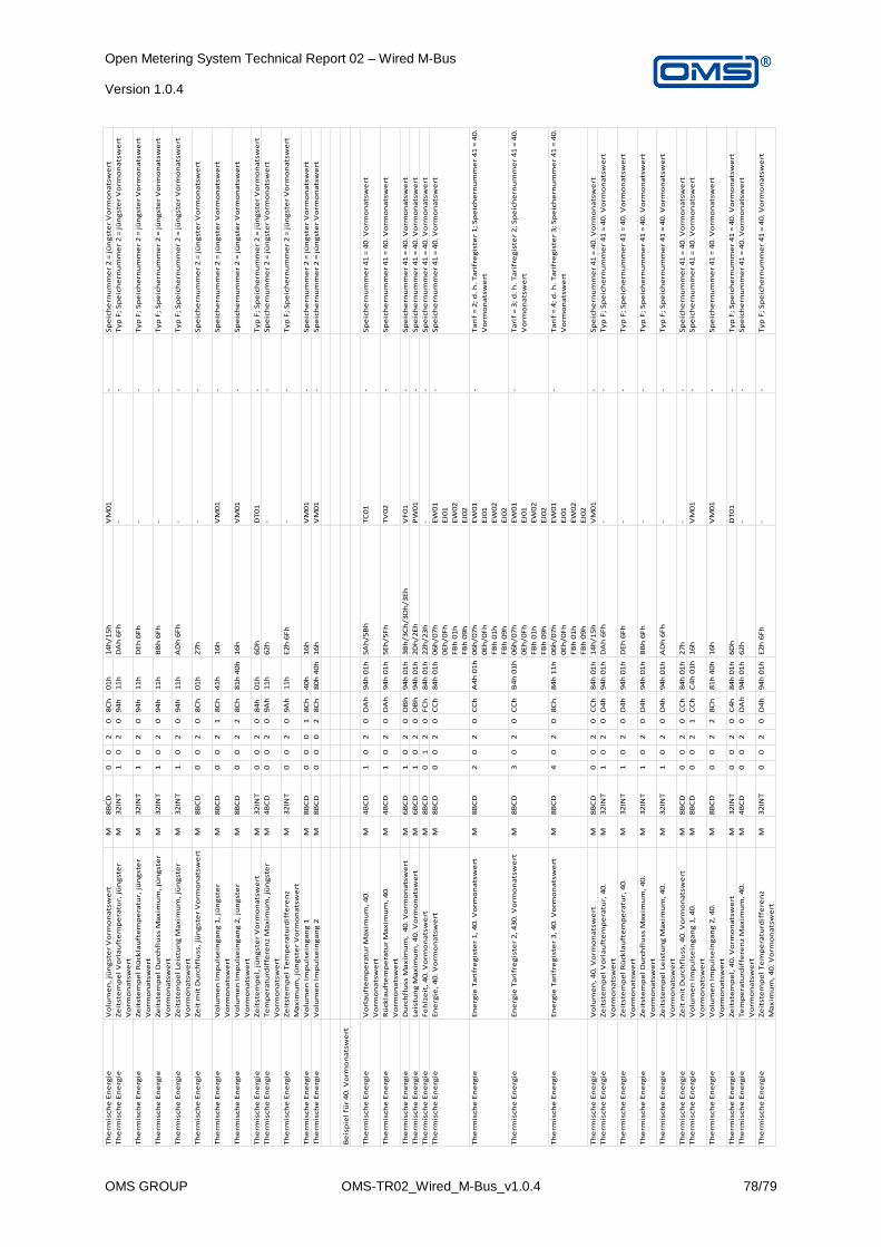
Open Metering System Technical Report 02 – Wired M-Bus Version 1.0.4
OMS GROUP OMS-TR02_Wired_M-Bus_v1.0.4 78/79
Th
erm
isch
e E
ne
rgie
Vo
lum
en
, jü
ng
ste
r V
orm
on
ats
we
rtM
8B
CD
00
20
8C
h0
1h
14
h/1
5h
VM
01
-S
pe
ich
ern
um
me
r 2
= j
ün
gst
er
Vo
rmo
na
tsw
ert
Th
erm
isch
e E
ne
rgie
Ze
itst
em
pe
l V
orl
au
fte
mp
era
tur,
jü
ng
ste
r
Vo
rmo
na
tsw
ert
M3
2IN
T1
02
09
4h
11
hD
Ah
6F
h-
-T
yp
F;
Sp
eic
he
rnu
mm
er
2 =
jü
ng
ste
r V
orm
on
ats
we
rt
Th
erm
isch
e E
ne
rgie
Ze
itst
em
pe
l R
ück
lau
fte
mp
era
tur,
jü
ng
ste
r
Vo
rmo
na
tsw
ert
M3
2IN
T1
02
09
4h
11
hD
Eh
6F
h-
-T
yp
F;
Sp
eic
he
rnu
mm
er
2 =
jü
ng
ste
r V
orm
on
ats
we
rt
Th
erm
isch
e E
ne
rgie
Ze
itst
em
pe
l D
urc
hfl
uss
Ma
xim
um
, jü
ng
ste
r
Vo
rmo
na
tsw
ert
M3
2IN
T1
02
09
4h
11
hB
Bh
6F
h-
-T
yp
F;
Sp
eic
he
rnu
mm
er
2 =
jü
ng
ste
r V
orm
on
ats
we
rt
Th
erm
isch
e E
ne
rgie
Ze
itst
em
pe
l Le
istu
ng
Ma
xim
um
, jü
ng
ste
r
Vo
rmo
na
tsw
ert
M3
2IN
T1
02
09
4h
11
hA
Dh
6F
h-
-T
yp
F;
Sp
eic
he
rnu
mm
er
2 =
jü
ng
ste
r V
orm
on
ats
we
rt
Th
erm
isch
e E
ne
rgie
Ze
it m
it D
urc
hfl
uss
, jü
ng
ste
r V
orm
on
ats
we
rtM
8B
CD
00
20
8C
h0
1h
27
h-
-S
pe
ich
ern
um
me
r 2
= j
ün
gst
er
Vo
rmo
na
tsw
ert
Th
erm
isch
e E
ne
rgie
Vo
lum
en
Im
pu
lse
ing
an
g 1
, jü
ng
ste
r
Vo
rmo
na
tsw
ert
M8
BC
D0
02
18
Ch
41
h1
6h
VM
01
-S
pe
ich
ern
um
me
r 2
= j
ün
gst
er
Vo
rmo
na
tsw
ert
Th
erm
isch
e E
ne
rgie
Vo
lum
en
Im
pu
lse
ing
an
g 2
, jü
ng
ste
r
Vo
rmo
na
tsw
ert
M8
BC
D0
02
28
Ch
81
h 4
0h
16
hV
M0
1-
Sp
eic
he
rnu
mm
er
2 =
jü
ng
ste
r V
orm
on
ats
we
rt
Th
erm
isch
e E
ne
rgie
Ze
itst
em
pe
l, j
ün
gst
er
Vo
rmo
na
tsw
ert
M3
2IN
T0
02
08
4h
01
h6
Dh
DT
01
-T
yp
F;
Sp
eic
he
rnu
mm
er
2 =
jü
ng
ste
r V
orm
on
ats
we
rt
Th
erm
isch
e E
ne
rgie
Te
mp
era
turd
iffe
ren
z M
ax
imu
m,
jün
gst
er
Vo
rmo
na
tsw
ert
M4
BC
D0
02
09
Ah
11
h6
2h
--
Sp
eic
he
rnu
mm
er
2 =
jü
ng
ste
r V
orm
on
ats
we
rt
Th
erm
isch
e E
ne
rgie
Ze
itst
em
pe
l T
em
pe
ratu
rdif
fere
nz
Ma
xim
um
, jü
ng
ste
r V
orm
on
ats
we
rt
M3
2IN
T0
02
09
Ah
11
hE
2h
6F
h-
-T
yp
F;
Sp
eic
he
rnu
mm
er
2 =
jü
ng
ste
r V
orm
on
ats
we
rt
Th
erm
isch
e E
ne
rgie
Vo
lum
en
Im
pu
lse
ing
an
g 1
M8
BC
D0
00
18
Ch
40
h1
6h
VM
01
-S
pe
ich
ern
um
me
r 2
= j
ün
gst
er
Vo
rmo
na
tsw
ert
Th
erm
isch
e E
ne
rgie
Vo
lum
en
Im
pu
lse
ing
an
g 2
M8
BC
D0
00
28
Ch
80
h 4
0h
16
hV
M0
1-
Sp
eic
he
rnu
mm
er
2 =
jü
ng
ste
r V
orm
on
ats
we
rt
Be
isp
iel
für
40
. V
orm
on
ats
we
rt
Th
erm
isch
e E
ne
rgie
Vo
rla
uft
em
pe
ratu
r M
ax
imu
m,
40
.
Vo
rmo
na
tsw
ert
M4
BC
D1
02
0D
Ah
94
h 0
1h
5A
h/5
Bh
TC
01
-S
pe
ich
ern
um
me
r 4
1 =
40
. V
orm
on
ats
we
rt
Th
erm
isch
e E
ne
rgie
Rü
ckla
uft
em
pe
ratu
r M
ax
imu
m,
40
.
Vo
rmo
na
tsw
ert
M4
BC
D1
02
0D
Ah
94
h 0
1h
5E
h/5
Fh
TV
02
-S
pe
ich
ern
um
me
r 4
1 =
40
. V
orm
on
ats
we
rt
Th
erm
isch
e E
ne
rgie
Du
rch
flu
ss M
ax
imu
m,
40
. V
orm
on
ats
we
rtM
6B
CD
10
20
DB
h9
4h
01
h3
Bh
/3C
h/3
Dh
/3E
hV
F0
1-
Sp
eic
he
rnu
mm
er
41
= 4
0.
Vo
rmo
na
tsw
ert
Th
erm
isch
e E
ne
rgie
Leis
tun
g M
ax
imu
m,
40
. V
orm
on
ats
we
rtM
6B
CD
10
20
DB
h9
4h
01
h2
Dh
/2E
hP
W0
1-
Sp
eic
he
rnu
mm
er
41
= 4
0.
Vo
rmo
na
tsw
ert
Th
erm
isch
e E
ne
rgie
Fe
hlz
eit
, 4
0.
Vo
rmo
na
tsw
ert
M8
BC
D0
12
0F
Ch
84
h 0
1h
22
h/2
3h
--
Sp
eic
he
rnu
mm
er
41
= 4
0.
Vo
rmo
na
tsw
ert
Th
erm
isch
e E
ne
rgie
En
erg
ie,
40
. V
orm
on
ats
we
rtM
8B
CD
00
20
CC
h8
4h
01
h0
6h
/07
h
0E
h/0
Fh
FB
h 0
1h
FB
h 0
9h
EW
01
EJ0
1
EW
02
EJ0
2
-S
pe
ich
ern
um
me
r 4
1 =
40
. V
orm
on
ats
we
rt
Th
erm
isch
e E
ne
rgie
En
erg
ie T
ari
fre
gis
ter
1,
40
. V
orm
on
ats
we
rtM
8B
CD
20
20
CC
hA
4h
01
h0
6h
/07
h
0E
h/0
Fh
FB
h 0
1h
FB
h 0
9h
EW
01
EJ0
1
EW
02
EJ0
2
-T
ari
f =
2;
d.
h.
Ta
rifr
eg
iste
r 1
; S
pe
ich
ern
um
me
r 4
1 =
40
.
Vo
rmo
na
tsw
ert
Th
erm
isch
e E
ne
rgie
En
erg
ie T
ari
fre
gis
ter
2,
43
0.
Vo
rmo
na
tsw
ert
M8
BC
D3
02
0C
Ch
B4
h 0
1h
06
h/0
7h
0E
h/0
Fh
FB
h 0
1h
FB
h 0
9h
EW
01
EJ0
1
EW
02
EJ0
2
-T
ari
f =
3;
d.
h.
Ta
rifr
eg
iste
r 2
; S
pe
ich
ern
um
me
r 4
1 =
40
.
Vo
rmo
na
tsw
ert
Th
erm
isch
e E
ne
rgie
En
erg
ie T
ari
fre
gis
ter
3,
40
. V
orm
on
ats
we
rtM
8B
CD
40
20
8C
h8
4h
11
h0
6h
/07
h
0E
h/0
Fh
FB
h 0
1h
FB
h 0
9h
EW
01
EJ0
1
EW
02
EJ0
2
-T
ari
f =
4;
d.
h.
Ta
rifr
eg
iste
r 3
; S
pe
ich
ern
um
me
r 4
1 =
40
.
Vo
rmo
na
tsw
ert
Th
erm
isch
e E
ne
rgie
Vo
lum
en
, 4
0.
Vo
rmo
na
tsw
ert
M8
BC
D0
02
0C
Ch
84
h 0
1h
14
h/1
5h
VM
01
-S
pe
ich
ern
um
me
r 4
1 =
40
. V
orm
on
ats
we
rt
Th
erm
isch
e E
ne
rgie
Ze
itst
em
pe
l V
orl
au
fte
mp
era
tur,
40
.
Vo
rmo
na
tsw
ert
M3
2IN
T1
02
0D
4h
94
h 0
1h
DA
h 6
Fh
--
Ty
p F
; S
pe
ich
ern
um
me
r 4
1 =
40
. V
orm
on
ats
we
rt
Th
erm
isch
e E
ne
rgie
Ze
itst
em
pe
l R
ück
lau
fte
mp
era
tur,
40
.
Vo
rmo
na
tsw
ert
M3
2IN
T1
02
0D
4h
94
h 0
1h
DE
h 6
Fh
--
Ty
p F
; S
pe
ich
ern
um
me
r 4
1 =
40
. V
orm
on
ats
we
rt
Th
erm
isch
e E
ne
rgie
Ze
itst
em
pe
l D
urc
hfl
uss
Ma
xim
um
, 4
0.
Vo
rmo
na
tsw
ert
M3
2IN
T1
02
0D
4h
94
h 0
1h
BB
h 6
Fh
--
Ty
p F
; S
pe
ich
ern
um
me
r 4
1 =
40
. V
orm
on
ats
we
rt
Th
erm
isch
e E
ne
rgie
Ze
itst
em
pe
l Le
istu
ng
Ma
xim
um
, 4
0.
Vo
rmo
na
tsw
ert
M3
2IN
T1
02
0D
4h
94
h 0
1h
AD
h 6
Fh
--
Ty
p F
; S
pe
ich
ern
um
me
r 4
1 =
40
. V
orm
on
ats
we
rt
Th
erm
isch
e E
ne
rgie
Ze
it m
it D
urc
hfl
uss
, 4
0.
Vo
rmo
na
tsw
ert
M8
BC
D0
02
0C
Ch
84
h 0
1h
27
h-
-S
pe
ich
ern
um
me
r 4
1 =
40
. V
orm
on
ats
we
rt
Th
erm
isch
e E
ne
rgie
Vo
lum
en
Im
pu
lse
ing
an
g 1
, 4
0.
Vo
rmo
na
tsw
ert
M8
BC
D0
02
1C
Ch
C4
h 0
1h
16
hV
M0
1-
Sp
eic
he
rnu
mm
er
41
= 4
0.
Vo
rmo
na
tsw
ert
Th
erm
isch
e E
ne
rgie
Vo
lum
en
Im
pu
lse
ing
an
g 2
, 4
0.
Vo
rmo
na
tsw
ert
M8
BC
D0
02
28
Ch
81
h 4
0h
16
hV
M0
1-
Sp
eic
he
rnu
mm
er
41
= 4
0.
Vo
rmo
na
tsw
ert
Th
erm
isch
e E
ne
rgie
Ze
itst
em
pe
l, 4
0.
Vo
rmo
na
tsw
ert
M3
2IN
T0
02
0C
4h
84
h 0
1h
6D
hD
T0
1-
Ty
p F
; S
pe
ich
ern
um
me
r 4
1 =
40
. V
orm
on
ats
we
rt
Th
erm
isch
e E
ne
rgie
Te
mp
era
turd
iffe
ren
z M
ax
imu
m,
40
.
Vo
rmo
na
tsw
ert
M4
BC
D0
02
0D
Ah
94
h 0
1h
62
h-
-S
pe
ich
ern
um
me
r 4
1 =
40
. V
orm
on
ats
we
rt
Th
erm
isch
e E
ne
rgie
Ze
itst
em
pe
l T
em
pe
ratu
rdif
fere
nz
Ma
xim
um
, 4
0.
Vo
rmo
na
tsw
ert
M3
2IN
T0
02
0D
4h
94
h 0
1h
E2
h 6
Fh
--
Ty
p F
; S
pe
ich
ern
um
me
r 4
1 =
40
. V
orm
on
ats
we
rt
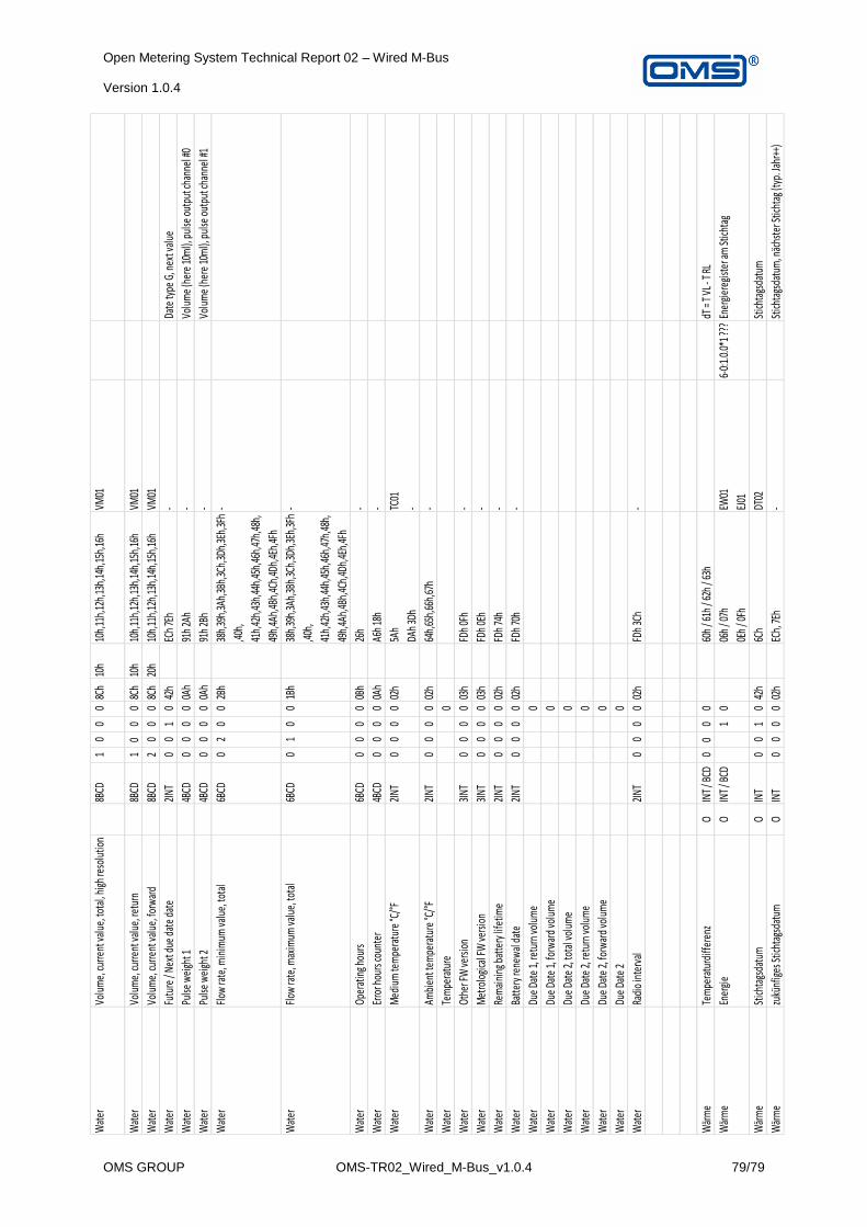
Open Metering System Technical Report 02 – Wired M-Bus Version 1.0.4
OMS GROUP OMS-TR02_Wired_M-Bus_v1.0.4 79/79
Wat
erVo
lum
e, cu
rrent
valu
e, to
tal,
high
reso
lutio
n8B
CD1
00
08C
h10
h10
h,11
h,12
h,13
h,14
h,15
h,16
hVM
01
Wat
erVo
lum
e, cu
rrent
valu
e, re
turn
8BCD
10
00
8Ch
10h
10h,
11h,
12h,
13h,
14h,
15h,
16h
VM01
Wat
erVo
lum
e, cu
rrent
valu
e, fo
rwar
d8B
CD2
00
08C
h20
h10
h,11
h,12
h,13
h,14
h,15
h,16
hVM
01
Wat
erFu
ture
/ Ne
xt d
ue d
ate
date
2INT
00
10
42h
ECh
7Eh
-Da
te ty
pe G
, nex
t val
ue
Wat
erPu
lse w
eigh
t 14B
CD0
00
00A
h91
h 2A
h-
Volu
me
(her
e 10
ml),
pul
se o
utpu
t cha
nnel
#0
Wat
erPu
lse w
eigh
t 24B
CD0
00
00A
h91
h 2B
h-
Volu
me
(her
e 10
ml),
pul
se o
utpu
t cha
nnel
#1
Wat
erFl
ow ra
te, m
inim
um va
lue,
tota
l6B
CD0
20
02B
h38
h,39
h,3A
h,3B
h,3C
h,3D
h,3E
h,3F
h
,40h
,
41h,
42h,
43h,
44h,
45h,
46h,
47h,
48h,
49h,
4Ah,
4Bh,
4Ch,
4Dh,
4Eh,
4Fh
-
Wat
erFl
ow ra
te, m
axim
um va
lue,
tota
l6B
CD0
10
01B
h38
h,39
h,3A
h,3B
h,3C
h,3D
h,3E
h,3F
h
,40h
,
41h,
42h,
43h,
44h,
45h,
46h,
47h,
48h,
49h,
4Ah,
4Bh,
4Ch,
4Dh,
4Eh,
4Fh
-
Wat
erOp
erat
ing h
ours
6BCD
00
00
0Bh
26h
-
Wat
erEr
ror h
ours
coun
ter
4BCD
00
00
0Ah
A6h
18h
-
Wat
erM
ediu
m te
mpe
ratu
re °C
/°F
2INT
00
00
02h
5Ah
DAh
3Dh
TC01
-
Wat
erAm
bien
t tem
pera
ture
°C/°
F2I
NT0
00
002
h64
h,65
h,66
h,67
h-
Wat
erTe
mpe
ratu
re0
Wat
erOt
her F
W ve
rsio
n3I
NT0
00
003
hFD
h 0F
h-
Wat
erM
etro
logi
cal F
W ve
rsio
n3I
NT0
00
003
hFD
h 0E
h-
Wat
erRe
mai
ning
bat
tery
life
time
2INT
00
00
02h
FDh
74h
-
Wat
erBa
ttery
rene
wal
dat
e2I
NT0
00
002
hFD
h 70
h-
Wat
erDu
e Da
te 1,
retu
rn vo
lum
e0
Wat
erDu
e Da
te 1,
forw
ard
volu
me
0
Wat
erDu
e Da
te 2,
tota
l vol
ume
0
Wat
erDu
e Da
te 2,
retu
rn vo
lum
e0
Wat
erDu
e Da
te 2,
forw
ard
volu
me
0
Wat
erDu
e Da
te 2
0
Wat
erRa
dio
inte
rval
2INT
00
00
02h
FDh
3Ch
-
Wär
me
Tem
pera
turd
iffer
enz
OIN
T / B
CD0
00
060
h / 6
1h /
62h
/ 63h
dT =
T VL -
T RL
Wär
me
Ener
gie
OIN
T / B
CD1
006
h / 0
7h
0Eh
/ 0Fh
EW01
EJ01
6-0:
1.0.
0*1 ?
??En
ergi
ereg
ister
am St
ichta
g
Wär
me
Stich
tags
datu
mO
INT
00
10
42h
6Ch
DT02
Stich
tags
datu
m
Wär
me
zukü
nfig
es St
ichta
gsda
tum
OIN
T0
00
002
hEC
h, 7E
h-
Stich
tags
datu
m, n
ächs
ter S
ticht
ag (t
yp. J
ahr+
+)