open access optimization of stone cutting techniques … · open access optimization of stone...
TRANSCRIPT

80 The Open Construction and Building Technology Journal, 2011, 5, (Suppl 1-M5) 80-88
1874-8368/11 2011 Bentham Open
a) b)
Open Access
Optimization of Stone Cutting Techniques for the Seismic Protection of Archaeological Sites
C. Cennamo*,1, B. Chiaia
2 and M. Di Fiore
2
1Faculty of Architecture, 2
nd University of Naples, Aversa, Italy;
2Department of Structural and Geotechnical Engineer-
ing, Polytechnic of Turin, Torino, Italy
Abstract: Since the beginning of civilization, history tells of the movement of art pieces, monuments and
manufacts from site to site. The causes are multiple: the displacements due to the "spoils of war", ordered by
kings and emperors, the movements caused by the need for reuse, especially in the early Christian period, and
so forth. Considerations about the events of the past, yield a possible strategy to transform this concept into a
technique for earthquake prevention of archaeological sites.
The seismic safety retrofits have often proven to be scarcely effective, because of the difficulties involved in
complex sites. The aim of this study is to analyze an “alternative” method of preventing natural disaster like
floods, eruption and earthquakes, through the movimentation of the most representative structural elements of
archaeological sites by decomposition of the masonry and marbles [1]. The procedure considers a process of
"cutting optimization," calibrated on the characteristics of the specific material that has to be cut and then dis-
placed in safer places (i.e., MEP, “manufact evacuation plan”).
This process should not create excessive problems to the structure, and aims to reassembly the manufact in
contexts able to guarantee safety through advanced earthquake-resistant expedients. From these considera-
tions, the work develops a procedure to safeguard the archaeological site of Pompei (Naples), through an ap-
propriate analysis of representative portions of the site, aimed to a careful handling and to a proper recon-
struction in a safe location, from the seismic point of view.
Keywords: Stone cutting, seismic protection, archaeological sites.
INTRODUCTION
Best Pratices from the Past
In the sixties, UNESCO decided to transfer a lot of Egyp-
tian art pieces considered in danger, in others safer places.
One important case was Abu Simbel on the Nile [2-8], an
archaeological site carved in rock in southern Egypt on the
rocky western shore of Lake Nasser, about 280 km south of
Aswan, which were in danger due to the construction of a
huge dam basin. In Fig. (1a), the statue of a sphinx partially
submerged by the waters of the Nile during the construction of the Aswan Dam is shown.
The dismantling, transportation and re-assembling work
required five years, more than 2.000 people and more than
40 million hours of working, 150 technicians from around
the world, tons of materials and an unprecedented techno-logical effort in the history of the engineering worldwide.
Their work ensured the millimetric mutual re-positioning
of the blocks. The temples were cut into thousands of pieces
before being assembled with absolute precision in the safe locations.
*Address correspondence to this author at the Seconda Università di Napoli,
Facoltà di Architettura, Italy; Tel: 0039815010825;
E-mails: [email protected]; [email protected]
Another Egyptian archaeological site dismantled, dis-placed and reassembled in a new location, is the Philae tem-ple complex Fig. (1b), which was moved brick to brick, to Agilkai 550 m away, from the original site to prevent flood-ing risk. Individual blocks were put in place with inverted order of dismantling. Tools and techniques similar to the ancient ones were used, in order to avoid any breakage. For lifting, mobile and fixed cranes using elastic bands of syn-thetic fibre, were used instead of destructive steel cables. The blocks from every building were transported and neatly ar-ranged, in the storage area of about 96,000 square meters.
Fig. (1). (a) Aswan: Statue of a Sphinx partially submerged by the
waters of the Nile after the construction of the dam. (b) General
view of the Philae complex.
The actual reassembly was based both on the instrumen-tal position of 558 blocks containing the topographical

Optimization of Stone Cutting Techniques for the Seismic Protection The Open Construction and Building Technology Journal, 2011, Volume 5 81
landmarks in stainless steel, both on the utilization of direct surveys. The adoption of the ancient techniques of masonry building with blocks and elastic mortar, were meant to avoid the placement of resins and cement joints between the blocks, that would not allow the elasticity of structures origi-nally planned.
More recently (2006), during the excavations for the new
underground line of Naples (Italy), a temple dedicated to the
Emperor Augustus (as a part of a larger Gymnasium com-
plex) was found, dating III-IV century a.C., under Piazza N.
Amore. The Authority of Cultural Heritage decided to cut
the structure into blocks (Fig. 2), then reassemble it partly in
the underground of the National Museum, and partly in the
metro station, when the excavation works will be finished.
The work presented difficulties mainly related to the phase
of reassembly of the blocks, because of the width of cut
caused by the use of hand saws, and the impossibility to use
wet cutting that could damage mosaics. Hence, the Authors
were asked to develop a study aimed at cutting optimization,
calibrating the speed and power of the machines with the characteristics of the specific material [9, 10].
Fig. (2). Cuts for the preparation of the blocks in the yard of Piazza
Nicola Amore (Naples, Italy, 2006-2007).
The blocks were made of tuff stones, with irregular shape and variable sizes, into a light gray mortar, of volcanic ori-gin. The first step was the chemical-physical and mechanical characterization of the material. Therefore experimental in-vestigations on fragments of material were carried out.
The chemical analysis, and in particularly the minera-
logical ones performed on tuff, showed the typical composi-
tion of the Neapolitan yellow tuff. Following the chemical
analysis, mechanical tests were carried out at Politecnico di
Torino in 2007, bringing the specimens to failure through
uniaxial compression. These permitted to evaluate the spread of mechanical characteristics among the elements.
The chemical and mechanical characterization provided a
true knowledge of the material, and encouraged the devel-
opment of a mechanical model for dry cutting, optimised
with respect to the specific material, which will be outlined in the next section.
OPTIMIZATION OF THE CUTTING PROCESS IN GEOMATERIALS
Kinematic Description
The kinematic and mechanical models developed for op-timizing the cutting process in geomaterials are here briefly described [9-15].
The first model, describes the progress of the teeth of the cut machine within the material, and depends on the shape, number and type of these. The second model balances the mechanical power supplied by the engine, with the consump-tion of energy during material cutting.
To describe energy dissipation, the concept of "cutting strength” is introduced, a characteristic parameter of the ma-terial, which represents the energy required to remove the unit of material volume. This quantity has the same physical dimension of the elastic modulus E. The parameters entering the cutting model are: the thrust of the machine N, the feed rate ˙ , the angular velocity ˙ , the depth of penetration of the single tooth u, the radius of the disk R, the points A and B of contact between the tooth and the generic block to be cut, and the material’s cutting strength C (Fig. 3).
Fig. (3). The geometrical parameters of the cutting model.
The kinematic assumption underlying the model is on the
trajectory described by the tooth into the material, that is
essentially a pseudo-cycloid, consisting of an active part,
able to enter the material, and a passive one. When the ma-
chine is fully operational, each tooth must be able to remove
the exact amount of material corresponding to its penetration depth.
The mechanical model for calculating the value of the
cutting strength C is based on the following parameters:
the performance of the machine, Pm the mechanical power,
nd the number of teeth on the disc, ndl the maximum number
of operational teeth, s the distance between two successive
teeth, t the groove width. The following relationships have
been obtained by imposing mechanical energy balance and kinematic compatibility [9]:
(1) Consider the cutting operation performed by the work-
man with the chainsaw in Fig. (4a) where a schematization of the process is contextually presented. According to this idealization, every active tooth of the chain (black coloured in Fig. (4b) penetrates the material with a velocity and

82 The Open Construction and Building Technology Journal, 2011, Volume 5 Cennamo et al.
a) b)
follows the rotation of the chain moving tangentially with respect to it with a peripheral speed v.
Fig. (4). Cutting operation (a) and its schematization (b).
Let be the angular velocity of the chain in radians per second, the number of cycles per second can be simply ob-tained dividing it by 2 and, if L is the perimeter of the chain measured in meters, the tangential velocity of the tooth v is given as:
(2)
where Req is the radius of a circular chain saw with the same perimeter.
Another important consideration is that the number of active teeth lying on the toe (i.e. where the curvature radius is small) is negligible with respect to the number of those ly-ing on the cutting front, which is almost straight. According to this statement, we neglected the contribute given by the previous ones so that the whole cutting process can be con-sidered as performed by a straight chain saw.
The Mechanical Model
Looking back to Fig. (4), N is the normal force which pushes the saw into the material (usually applied manually) while T is the shear force that the engine provides to the chain. Moreover, let us call nd the total number of teeth and ndl the number of the active ones. Thus, if s is the length of the gullet between two consecutive teeth, then (Fig. 5):
(3)
where La is the length of the chain’s portion whose corre-sponding teeth are active. If the saw and its teeth are consid-ered infinitely rigid with respect to the material, which is homogeneous in terms of elastic coefficients and cutting strength, the shear and normal external forces (i.e. T and N) can be equally distributed between the active teeth obtaining:
(4)
Now let us adopt the following relation between the force fn applied to an indenter and its penetration u into the mate-rial:
(5)
where k and are constants depending on the base mate-rial, on the indenter geometry and on the tool wear state. If the process is optimised (this reduces vibrations ad provides regime regularity, reducing the risk of damage to the cut objects) then and v must be constants. This implies that every tooth always shows the same penetration depth u* given as:
(6)
and that the trajectory of the active teeth is linear. An active tooth moves for s in the horizontal direction while spanning the gullet between two successive teeth s in the vertical di-rection. Thus the penetration u can be kept constant (u*) only if s = u* .
The consequences of the violation of the above condition will be discussed later in this section.
Therefore, in the optimal condition it can be easily obtained:
(7)
On the other hand, since in the steady state the engine provides a constant shear force T to the chain, the work We(s) done by the engine to move the chain for a length s is:
We s( ) = Ts (8)
where is the efficiency of the cutting process.
Fig. (5). Material removed during the vertical advancement equal to
s (left side) and particular of a tooth (right side).
Considering that s=vts, the power requested W'e is:
W 'e = Tv (9)
Finally, if we define the cutting strength C (eq. 1) as the amount of energy requested to remove a unitary volume of material, then the energy required to make all the active teeth advance for a length s is:
Wrem (s) = Cu * tLa (10)
where t is the tooth width.
Recalling equations (3), (8) and (10), from a simple en-ergy balance we obtain:
T = Cu*tndl (11)

Optimization of Stone Cutting Techniques for the Seismic Protection The Open Construction and Building Technology Journal, 2011, Volume 5 83
The introduced parameter, the cutting strength, has the dimension of a force per unit area exactly as a plastic strength. Nevertheless, it is actually larger than the ultimate quasi-static compressive strength since it takes into account also the energy dissipated by friction, heating, fragmentation, milling and depends on the fracture mechanisms induced by the tooth which, in turn, depend on the geometry of the cut-ter, on the activated friction, on the flushing liquid etc.
Finally, combining the previous Equations, the following formula can be obtained:
(12)
which puts into relation the penetration velocity, the power applied by the engine (and its efficiency), the cutting strength, the number of active teeth and their width.
Fig. (6). Schematic representation of the optimal relations between
geometrical and mechanical parameters involved in the cutting
operations.
The previous model (Fig. 6) suggests that the optimal
cutting process, in terms of required energy and for a con-
stant applied power, cannot be obtained by changing the
geometrical features of the cut (except for the groove width
t) or the number of teeth. Actually, the cutting strength can
be minimized either by choosing the optimal value of the
penetration u* (or, which is the same, the optimal value of
the applied normal force) and choosing the optimal shape of
the teeth, because these determine the fracture mechanisms that are triggered.
A PROPOSAL FOR SEISMIC SAFETY OF POMPEI
Pompei is one of the city of the Vesuvian area highly
subject to seismic risk of both volcanic and tectonic origin.
Moreover it is exposed to pyroclastic flows with high speeds
and temperatures that could destroy the site in a short time, in case of eruption of Vesuvio.
Pompei is also located in the "red zone" (Fig. 7), identi-
fied by the seismologists as the highest seismic risk area in the region.
Fig. (7). Location of the archaeological site of Pompei in the “red
area” around Vesuvio.
This simplification, however, appears too schematic, when related to a modern hazard theory. Volcanic risk is based on past history of the volcano, and it is defined as the product of the Exposed Value, the Site Vulnerability and the Hazard, where the first term is the number of living people, or the value of the property at risk in a volcanic area, the second represents the sensitivity of buildings and manufacts to damage under a certain event, and the third is the prob-ability that a given area is subject to a certain destructive volcanic event. subject to a certain destructive volcanic event. This definition takes into account the natural phenom-ena and their probability of occurrence, with the effects that they may cause on the living environment.
Carrying the analysis on these parameters, it can be shown that, as we have already said, the majority of sites are mostly affected by the so-called "precursors phenomena” of the eruptive event, including the earthquakes that are the most destructive and whose energy may partly be limited by human technology. Geologists warn that the seismic wake preceding a possible volcanic eruption can last for days, damaging even structures that could be saved since located away from the crater.
Plinio "il Giovane" wrote about the seismic events that occurred in Flegrea area following the famous eruption of Vesuvius in 79 b.C.: “Previously, for a period of several days, the earth was trembling although we did not scare too much, because the earthquakes are a normal phenomenon in Campania. But that night, the earth shook with great vio-lence, and it seemed that everything was not shaken, but turned upside.[...]”.
One of the most exposed areas is the Insula del Cente-nario [16], which also represents one of the most valuable parts of the Pompei archaeological site. Therefore, we try to define a “knowledge status” for this site, in order to propose a strategy for movimentation and reassembly for protection.
The Building Materials Found in the Insula del Centenario, Pompei
The most diffused building materials in the Insula del Centenario are: the Sarno limestone, the lava stone, the spume of lava, the yellow tuff of the Flegrea area and the gray tuff of Nocera [16-18].

84 The Open Construction and Building Technology Journal, 2011, Volume 5 Cennamo et al.
The calcare of Sarno is a sedimentary rock of calcium carbonate formed by debris from the river Sarno. It looks rough and porous with the presence of footprints plants and fossilized reeds. Cutting is easy (low hardness), however it tends to harden in contact with air, therefore offers a certain resistance.
The lava stone is a type of lava formed by the consolida-tion of volcanic cinders, extracted from the lower level of the lava. It is very rough and dotted by two types of phoeno-crystals: augite (blackish and prismatic) and leucite (whitish and round).
The spume of lava is another kind of lava extracted from the top of the flow. It originates from the solidification of a magma rich in volatile gases that, degassed, generate bubbles (it looks like a petrified sponge). In section, phoeno-crystals of leucite are noticed. It is porous, very light and easy to work, ill-suited for decorations.
The yellow tuff is a pyroclastic type of rock characterized by a high presence of oxides and hydroxides of iron. It is very soft and sensitive to erosion.
The gray tuff of Nocera also belongs to pyroclastic rocks, and is characterized by fine and compact grains with black-ish and brown pieces, formed by sedimentation of volcanic products (ashes, lapilli, lava). It is easy to work just extracted from the quarry then it hardens in the air (Table 1)
Table 1. Building base Materials in the Insula del Centenario
Regarding mortars, four types, different for components, colour, texture and building techniques used, can be identi-fied [16-20].
The mortar type A is characterized specifically by a low presence of smectite and of abundant calcite. It contains abundant feldspar, quartz and amphiboles/pyroxenes some-times in significant percentages. It shows different colours and large clasts of calcite. This type of mortar is used pri-marily in association with opus incertum and opus vittatum.
It is also used externally as finishing (rinzaffo) on the manu-fact, showing the unequivocal time of intervention.
The mortar type B is distinguished from type A by the absence of smectite. It contains abundant calcite and rare pyroxene and amphiboles. This type of mortar is used as a binder in opus incertum and in vittatum. It is also distributed on some opus africanum walls and on opus incertum walls.
The mortar type C is the modern one, e.g. is a concrete, thus it is easily identifiable and dated.
Indeed, it may be differentiated into three subtypes, de-pending on whether it is related to repairs carried out be-tween the nineteenth and twentieth century, to interventions of the '60s and '70s of the last century, or to the final restora-tions of the XXI century.
The mortar type D has yellowish colour, with silty/clay content, scant binder and very crumbly texture. It is charac-terized easily by the low amount of calcite, by the abundance of quartz and mica and by the absence of pyroxenes, amphi-boles and smectite. It is easily distinguishable also on the work field: this type of mortar is always combined with opus africanum, thus becoming the true chronological indicator, especially in cases of reuse.
Beyond the type C mortar, which contains modern ce-ment components, and is therefore associated to pseudo-ancient building techniques or to recent retrofits, the result of great interest is that the remaining three types of mortar are in association with specific construction techniques.
From the distribution of mortars, confirmed and supple-mented by stratigraphic evidence, we notice that the mortar D is covered by types A and B, while B covers type A. It follows that interventions with mortar B occurred later than those executed with mortar A, and are both used later than to mortar D (Table 3).
Table 2. Summary of the Characteristics of the Mortars in
the Insula del Centenario
MORTARS
COMPONENTS
COL-
ORS/TEXTURE
BUILDING
TECHNIQUE
Type A
- hydromagnesite
- few quarz - few nodules volca-
noes (pyroxenes and amphiboles)
- light brown - clayey matrix
- white lumps
Opus incertum
Opus vittatum
Type B
- hydromagnesite - abundant quartz
- few volcanic nodules
- yellowish colour
- smeared aspect - fluid consistency
Opus incertum
Opus vittatum
Type C
- modern concrete
- volcanic lapilli
- dark gray color
- very toughtexture
Retrofits and
modern inter-ventions
Type D - quarz and mica
- yellowish colour - very sandy
matrix
Opus afri-canum
In Fig. (8), a typical floor plan and a schematic classifica-
tion of the old mortar types within the Insula are represented.
Fundamental Aspects of the Construction Techniques

Optimization of Stone Cutting Techniques for the Seismic Protection The Open Construction and Building Technology Journal, 2011, Volume 5 85
Analyzing the masonry of the Insula del Centenario, in several places -where the wall structure was exposed to at-mospheric agents- a yellowish colour lime mortar, analyzed in Table 2 with the Type B denomination, looking like a grouting around the blocks of stones, was noted.
Fig. (8). Insula del Centenario floor plan.
To first hypothesis, this could be a modern retrofit with the aim to protect and strengthen the masonry. Instead, by a closer examination, this mortars was found also in corre-spondence of the gaps due to failure of plasters, and there-fore, it belongs to older periods, and represents an interven-tion of wall finishing [16-19].
Table 3. Classification of the four types of mortars found in
the Insula
Mortar D Mortar A Mortar B Mortar C
Opus afri-
canum
Opus incertum Opus incertum Retrofits
Samnite age
(III-II sec.
b.C.)
Proto empire age
(15 a.C. )
Flavia age
(70-79 a.C.)
Modern age
(1879-2001)
- CASE AD
ATRIUM
AND
HORTUS
- THERMAE
- LUPANARE
- ATRIOLO
SERVILE
- APPAR-
TAMENTO
DELLA
DOMINA
- RESTORA-
TION
- CASA DEL CENTE-
NARIO WITH DOUBLE
HALL AND
PERISTYLE
- RESTORATION
This intervention is present in many areas of the Insula, and for large extensions too. The mortar used for the finish-ing, has a fairly uniform colour and appears very homogene-ous. A great difference is noticed between inner mortar and external one, exposed to the atmosphere (Fig. 9).
The internal mortar is composed by aggregates with vari-able size, that is, without particular choices or screening ac-
tions. Instead, the composition of the mortar used for the implementation of the finishing reveals a thin and uniform grain size. This testifies a major concern in the choice both of the binder and of the aggregate.
More specifically, this intervention was used to smooth the wall surface, closing the gaps between the stones, but it also allowed penetration of the mortar deep, with the aim to fill the gaps and give a better static strength to the structure.
Fig. (9). External crushed mortar and internal mortar.
The ancient inhabitants of Pompei used a kind of "trainer", consisting of timber planks with the function of maintaining the alignment of the walls being built. The boards were supported, for a certain portion of their width, to the already built wall, and held in position by oblique props anchored at the terrain (Fig. 10). The width that had to ad-here to the built wall, had to be sufficiently large to ensure a proper alignment.
Fig. (10). Representation of the "train table" for the construction of
an opus caementicium wall.
A part of the table had to exceed the level of the already built wall, for a sufficient span allowing the workers to reach the last placed stone blocks, and then to put the new ones upon.
After placing the table on both sides of the wall, the ma-sons stretched, on the already built wall, a certain amount of mortar with the trowel. Above they placed the stone blocks, trying to arrange them so that they coincide as much as pos-sible with the close ones, therefore leaving few gaps. The work proceeded by constructing the two sides of the wall, and by filling the holes through "zeppe" (thin pieces of stone), with the aim to use less mortar.
The main building techniques were: the opus africanum, the opus incertum, the opus vittatum mixtum and the opus latericium [16-20]. The opus africanum, of Punic origin, but reworked locally around the first quarter of the third century b.C., is mainly used for load-bearing walls. It consists of large blocks of Sarno limestone, positioned orthogonally to each other, constituting a "frame" whose interior is filled with opus incertum or limestones, originally assembled dry and later with mortar (Fig. 11).

86 The Open Construction and Building Technology Journal, 2011, Volume 5 Cennamo et al.
The opus incertum, mentioned by Vitruvius as the build-ing technique used before his generation (opus antiquum, quod incertum dicitur), represents a development of the opus coementicium and spreads in the Campania area at the end of the third century b.C. It consists of three layers: the outer garments, usually of Sarno limestone, brick or volcanic rocks, and the core consisting of fragments of various mate-rials cemented with mortar, thus limiting the micro-fractures, using the technique that Vitruvio defined "èmplekton" (i.e., the modern sack masonry). The enormous spread of this technique in Pompei is due to the celebrated high building quality of the pozzolana of volcanic origin, present in the subsoil (Fig. 12).
Fig. (11). Example of opus africanum and particular of the
speculum image.
Fig. (12). a) Example of opus incertum with majority of Sarno
limestone and corner link in opus vittatum, with two courses of
bricks alternated with a row of tuff blocks. b) Example of opus
incertum with a predominantly volcanic rock and corner link made
by opus vittatum mixtum.
The opus vittatum mixtum was used primarily after an-other great earthquake occurred in Pompei in 62 a.C. It is a “sack” masonry like opus incertum. The garments are made of stone blocks, usually limestone, placed in horizontal rows, similar in shape to bands (the vittae), and very often inter-rupted by rows of bricks with highly variable frequency.
This technique was used primarily in corners between walls (ammorsamenti) and for additions or retrofits after seismic damage.
Even the opus latericium was used in this period with a primary function of consolidation and restoration of dam-aged masonry. The technique consisted in a brickwork layer with an inner core of opus caementicium, with a more or less regular form.
Determination of the Cutting Strength of Stone Materials in Pompei
The cutting strength C can be considered, in a first ap-proximation, proportional to the strength u of the material. It can be considered, another characteristic of the material. Putting into relation the u and the C derived from labora-tory tests performed on material found in Naples, with the u of some Pompei materials, the cutting strength of these mate-rials can be derived, as a first approximation.
The cutting strength C of the materials found in Piazza Nicola Amore in Naples varies between 200 to 600 Mpa, therefore the average value equal to 400 Mpa will be used. Opus Vittanum mixtum, Opus incertum, Opus latericium and Opus africanum from Pompei are considered:
. opus africanum u=11 Mpa C=650 Mpa;
. opus incertum u=4,22 Mpa C=251 Mpa;
. opus vitattum mixtum u=4,22 Mpa C=251 Mpa;
. opus latericum u=7,7 Mpa C=460 Mpa.
Thus, the C value of the archaeological materials under examination varies between 250 to 650 Mpa. Therefore, the average value C equal to 450 Mpa is considered.
From simple geometrical considerations [9], we get:
Adl =ndl
nd
2 Rt (13)
and replacing equation (13) into eq. (1), the following rela-tion is obtained
C =Pm
&Adl
(14)
The equation (14) is valid only under in the hypothesis of circular disk saw: in fact the term Adl, that appears in its de-nominator, is calculated as a function of the radius of the disk R.
However, taking into account the meaning of Adl [9]
tii=1
ndlsi = Adl (15)
where si is the distance between the i-th tooth and the next one, and ti is the width of the groove generated by the i-th single tooth, the following relationship, is obtained:
C =Pm
&Adl
=Pm
& ti sii=1
ndl=
Pm&ndlts
(16)
Taking into account the previous relation, and using commercial saws, from eq. (16) we obtain:
& =Pm
CAdl
(17)
In this way it is possible to determine the velocity of ad-vancement necessary to realize an optimal cut for each of the considered Pompei materials. In particular, to obtain an op-timal cutting process in the case of masonry of Pompei, one should adopt the following optimal advancement speeds:
opus africanum & = 0,69 cm/s
Optimization of Stone Cutting Techniques for the Seismic Protection The Open Construction and Building Technology Journal, 2011, Volume 5 87
opus incertum & = 1,78 cm/s
opus vittanum mixtum & = 1,78 cm/s
opus latericium & = 0,97 cm/s
The "Manufact Evacuation Plan" (MEP)
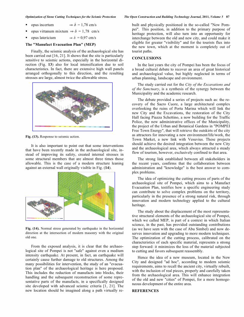
Finally, the seismic analysis of the archaeological site has been carried out [16, 21]. It shows that the site is particularly sensitive to seismic actions, especially in the horizontal di-rection (Fig. 13) also for local intensification due to soil characteristics. In fact, there are extensive high wall panels arranged orthogonally to this direction, and the resulting stresses are large, almost twice the allowable stress.
Fig. (13). Response to seismic action.
It is also important to point out that some interventions that have been recently made in the archaeological site, in-stead of improving its safety, created internal stresses in some structural members that are almost three times those allowable. This is the case of a modern structure leaning against an external wall originally visible in Fig. (14).
Fig. (14). Normal stress generated by earthquake in the horizontal
direction at the intersection of modern masonry with the original
old one.
From the exposed analysis, it is clear that the archaeo-logical site of Pompei is not "safe" against even a medium intensity earthquake. At present, in fact, an earthquake will certainly cause further damage to old structures. Among the many possibilities for intervention, the study of an "evacua-tion plan" of the archaeological heritage is here proposed. This includes the reduction of manufacts into blocks, their handling and the subsequent reconstruction of some repre-sentative parts of the manufacts, in a specifically designed site developed with advanced seismic criteria [1, 21]. The new location should be imagined along a path virtually re-
built and physically positioned in the so-called "New Pom-pei"..-This position, in addition to the primary purpose of heritage protection, will also turn into an opportunity for interchange between the old and new city, and could make it eligible for greater "visibility" and for the tourists flux into the new town, which at the moment is completely out of tourist paths.
CONCLUSIONS
In the last years the city of Pompei has been the focus of a broad cultural debate to recover an area of great historical and archaeological value, but highly neglected in terms of urban planning, landscape and environment.
The study carried out for the City of the Excavations and of the Sanctuary, is a synthesis of the synergy between the Municipality and the academic research.
The debate provided a series of projects such as: the re-covery of the Sacro Cuore, a large architectural complex overlooking the ruins of Porta Marina which will link the new City and the Excavations, the restoration of the City Hall facing Piazza Schettino, a now building for the Traffic Police, the new administrative offices of the Municipality, the project of the Urban and Botanical Gardens in "POMPEI Free Town Energy", that will retrieve the outskirts of the city as attractors for innovating a new environment/life/work, the Town Market, a new link with Vesuvius. These projects should achieve the desired integration between the new City and the archaeological area, which always attracted a steady flow of tourism, however, exclusively confined to that area.
The strong link established between all stakeholders in the recent years, confirms that the collaboration between administration and "knowledge" is the best answer to com-plex problems.
The idea of optimizing the cutting process of parts of the archaeological site of Pompei, which aims to a Manufact Evacuation Plan, testifies how a specific engineering study can contribute to solve complex problems on the territory, particularly in the presence of a strong natural risk, through innovation and modern technology applied to the cultural heritage.
The study about the displacement of the most representa-tive structural elements of the archaeological site of Pompei, which we called MEP, is part of a context in which Italian science, in the past, has provided outstanding contributions (as we have seen with the case of Abu Simbel) and now de-serves innovation and upgrading to more modern techniques. The optimization of the cutting process, calibrated on the characteristics of each specific material, represents a strong step forward: it minimizes the loss of the material subjected to cutting and favors subsequent reassembly.
Hence the idea of a new museum, located in the New City and designed "ad hoc", according to modern seismic requirements, aims to recall the ancient city, virtually rebuilt, with the inclusion of real pieces, properly and carefully taken from the archaeological area. This will enhance integration of the old and new "cities" of Pompei, for a more homoge-neous development of the entire area.
REFERENCES

88 The Open Construction and Building Technology Journal, 2011, Volume 5 Cennamo et al.
[1] M. Di Fiore, "Metodologie per la prevenzione e la protezione dei
siti archeologici a rischio sismico: un’applicazione a Napoli ed una proposta per Pompei", Master Thesis in Architettura U.E., Univer-
sità degli Studi di Napoli S.U.N., 2009. [2] G. Gester, "Saving the Ancient Temples at Abu Simbel", National
Geographic Magazine, May 1966. [3] G. Gester, "Abu Simbel’s Ancient Temples Reborn", National
Geographic Magazine, May 1969. [4] VBB Vattenbyggnadsbyran, "The Salvage of the Abu Simbel Tem-
ples", Concluding Report, Stockholm, 1976. [5] W. MacQuitty, Abu Simbel. London: MacDonald & Co, 1965.
[6] C. D. Noblecourtand, and C. Kuenz, "Le petit temple d'Abou Sim-bel. Ministère de la Culture", Le Caire, 1968.
[7] G. Belzoni, Narrative of the Operations and Recent Discoveries in Egypt and Nubia, London: J. Murray, 1820.
[8] L. Greener, High Dam over Nubia. London: Cassell & Co, 1962. [9] C. Cennamo, B. Chiaia, and E. Masoero, "Optimization of Cutting
Process for Ancient Masonry: The Greek Gymnasium In Naples", International Journal of Architectural Heritage, vol. 3, no. 3, pp.
235-257, 2008. [10] C. Cennamo, B. Chiaia, and E. Masoero, "Optimization of cutting
processes in archaeological sites", in Proceedings of 6th Interna-tional Conference on Structural Analysis of Historical Construc-
tions, Bath, 2008. [11] B. Chiaia, "Fracture Mechanisms Induced in A Brittle Material by
A Hard Cutting Indenter", International Journal of Solids and Structures, vol. 38, no. 44/45, pp. 7747-7768, 2001.
[12] M. Borri Brunetto, A. Carpinteri, and B. Chiaia, "A model for con-crete perforation based on the concept of drilling strength", in Pro-
ceedings of International Conference FRAMCOS V, Vail (CO), U.S.A., 2004.
[13] A. K. Wojtanowicz, and E. Kuru, "Mathematical Modelling of Pdc
Bit Drilling Process Based on Single Cutter Mechanics", ASME Journal of Energy Resources Technology, vol. 115, no. 4, pp. 247,
1993. [14] D. Miller, and A. Ball, "Rock Drilling With Impregnated Diamond
Microbits - An Experimental Study", International Journal of Rock Mechanics and Mining Sciences, vol. 27, pp. 363-371, 1990.
[15] D. A. Glowka, "Use Of Single-Cutter Data in the Analysis of Pdc Bit Design: Part 1- Development of A Pdc Cutting Force Model",
Journal of Petroleum Technology, vol. 33, pp. 797-849, 1989. [16] S. Santoro, Pompei. Insula del Centenario (IX,8) I. Indagini
diagnostiche geofisiche e analisi archeometriche, Bologna: Ante Quem, 2007.
[17] G. Fiorelli, Pompeianorum Antiquitatum Historia, I-III, Napoli, 1860-64.
[18] R. Ginouvès, and R. Martin, Dictionnaire méthodique de l'ar-chitecture grecque et romaine. Matériaux et techniques de con-
struction, techniques et formes du décor, Paris, 1985. [19] A. Giordano, E. Mele, and A. De Luca, "Modelling of Historical
Masonry Structures: Comparison Of Different Approaches Through A Case Study", Engineering Structures, vol. 24, pp. 1057-
1069, 2002. [20] H. O. Lamprecht, Opus Caementicium: Bautechnik der Romer,
Düsseldorf, 1995. [21] C. Cennamo, B. Chiaia, and M. Di Fiore, “Masonry cutting and
dismantling for the protection of archaeological sites”, in Proceed-ings of 4th International Congress Science and Technology for the
safeguard of Cultural Heritage of the Mediterranean Basin, Cairo, 2009.
Received: June 15, 2011 Revised: August 25, 2011 Accepted: August 30, 2011
© Cennamo et al.; Licensee Bentham Open.
This is an open access article licensed under the terms of the Creative Commons Attribution Non-Commercial License (http://creativecommons.org/-
licenses/by-nc/3.0/) which permits unrestricted, non-commercial use, distribution and reproduction in any medium, provided the work is properly cited.