one way slab 10.01.03.162
TRANSCRIPT
AHSANULLAH UNIVERSITY
OF SCIENCE AND
TECHNOLOGY
Pre-stressed concrete lab
CE 418
COURSE TEACHER
Mr.Galib Muktadir & Sabreena N.Mouri


NAME OF MY TOPIC
1. Definition & types of slab
2. Definition of one-way slab
3. Figure of one-way slab
4. Design considerations of one-way slab
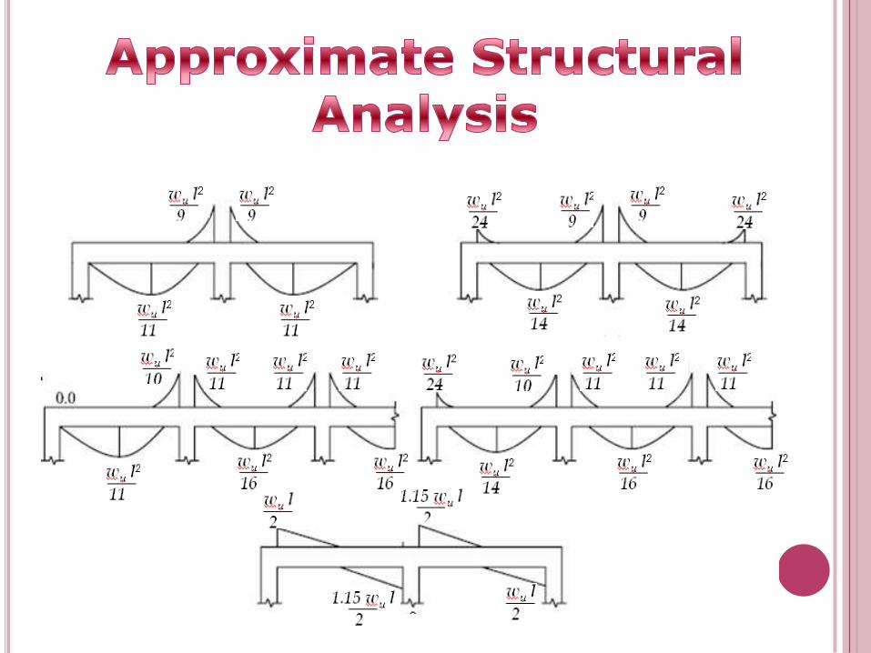
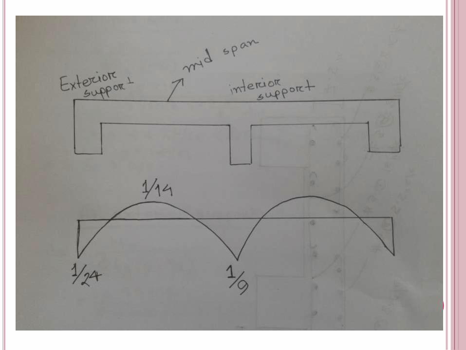
5. Approximate structural analysis
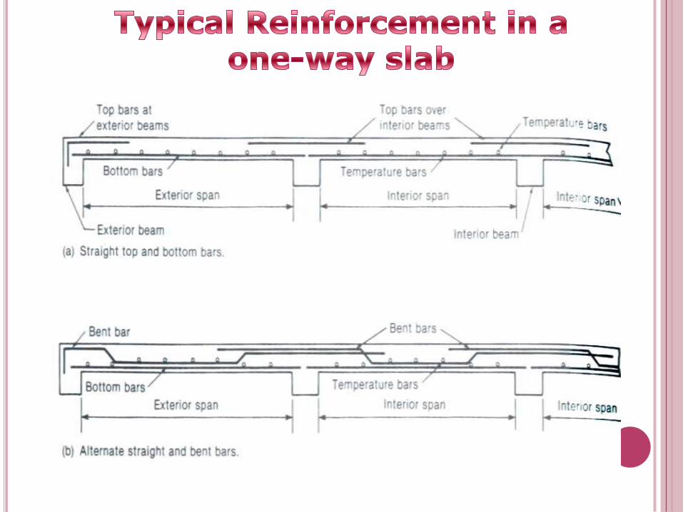
6. Typical reinforcement in a one-way slab
7. Summary of one-way slab design procedure
8. Example of one-way slab
FIRST WE WILL KNOW ABOUT SLABS; LIKE
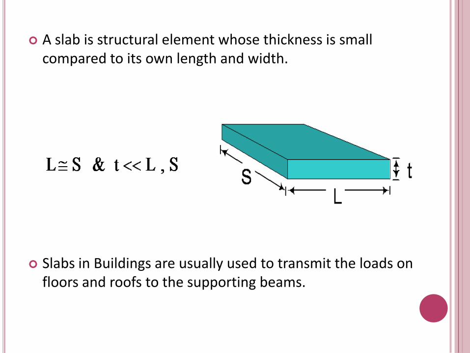
A slab is structural element whose thickness is small compared to its own length and width.
Slabs in Buildings are usually used to transmit the loads on floors and roofs to the supporting beams.
One-way slab
Two-way slab
Flat plate
Flat slab
Grid or waffle slab
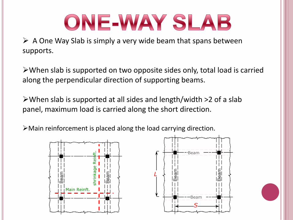
A One Way Slab is simply a very wide beam that spans between supports.
When slab is supported on two opposite sides only, total load is carried along the perpendicular direction of supporting beams.
When slab is supported at all sides and length/width >2 of a slab panel, maximum load is carried along the short direction.
Main reinforcement is placed along the load carrying direction.
Main Reinft.
shri
nkage R
ein
ft.
L
S
Beam
Beam
The slab is designed as a series of 1’-0” wide beam “strips”. The analysis is similar to rectangular beams, except the width b = 12” and the height is usually on the order of 4” →10”.
The main tension bars are usually #4, #5 or #6 bars. however, additional bars are placed perpendicular to the main tension bars to prevent cracking during the curing process. These bars are referred to as “shrinkage” or “temperature” bars and are also usually
#4 or #5 bars.

A one-way slab is supported by parallel walls or beams, and the main tension reinforcing bars run parallel to the span. It looks like the following:
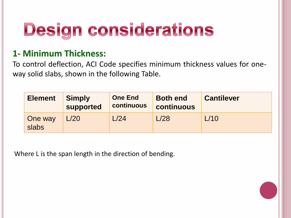
1- Minimum Thickness:To control deflection, ACI Code specifies minimum thickness values for one-way solid slabs, shown in the following Table.
Element Simply
supported
One End
continuousBoth end
continuous
Cantilever
One way
slabs
L/20 L/24 L/28 L/10
Where L is the span length in the direction of bending.
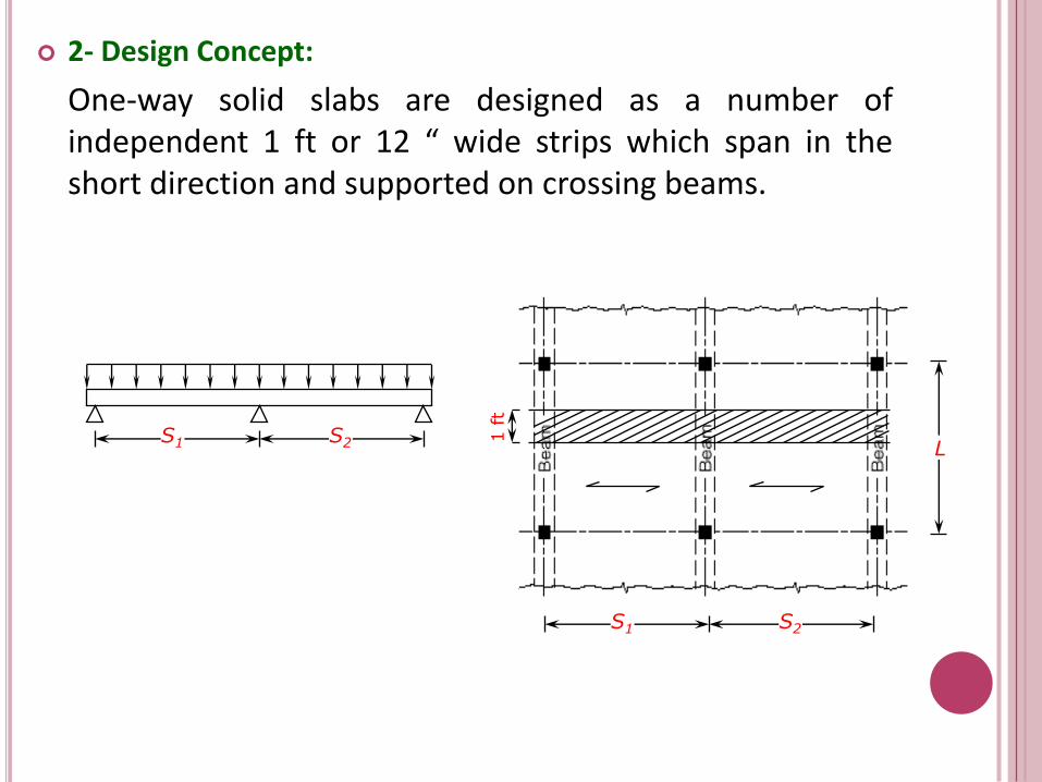
2- Design Concept:
One-way solid slabs are designed as a number of independent 1 ft or 12 “ wide strips which span in the short direction and supported on crossing beams.
1 ft
S2S1
LS2S1
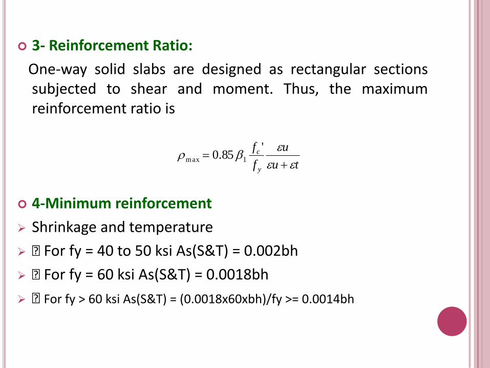
3- Reinforcement Ratio:
One-way solid slabs are designed as rectangular sections subjected to shear and moment. Thus, the maximum reinforcement ratio is
4-Minimum reinforcement
Shrinkage and temperature
„ For fy = 40 to 50 ksi As(S&T) = 0.002bh
„ For fy = 60 ksi As(S&T) = 0.0018bh
„ For fy > 60 ksi As(S&T) = (0.0018x60xbh)/fy >= 0.0014bh
tu
u
f
f
y
c
'85.0 1max

5- Spacing of Reinforcement Bars
S=( 12 * as) / As
here , as = area of the bar used ,
As = area of reinforcement
6- Loads Assigned to Slabs
wu=1.2 D.L + 1.6 L.L
7-Minimum cover
„ ACI 7.7.71 (if not exposed to weather or in contact with soil)„
¾ in. for # 11 and smaller
1.5 in. for # 14 and # 18 bars


1- Select representative 1ft wide design strip/strips to span in the short direction.
2- Choose a slab thickness to satisfy deflection control requirements. When several numbers of slab panels exist, select the largest calculated thickness.
3- Calculate the factored load wu by magnifying service dead and live loads according to this equation wu=1.20wD +1.60wL .
4- Draw the shear force and bending moment diagrams for each of the strips.
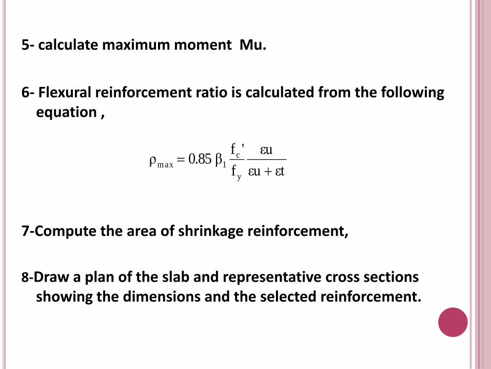
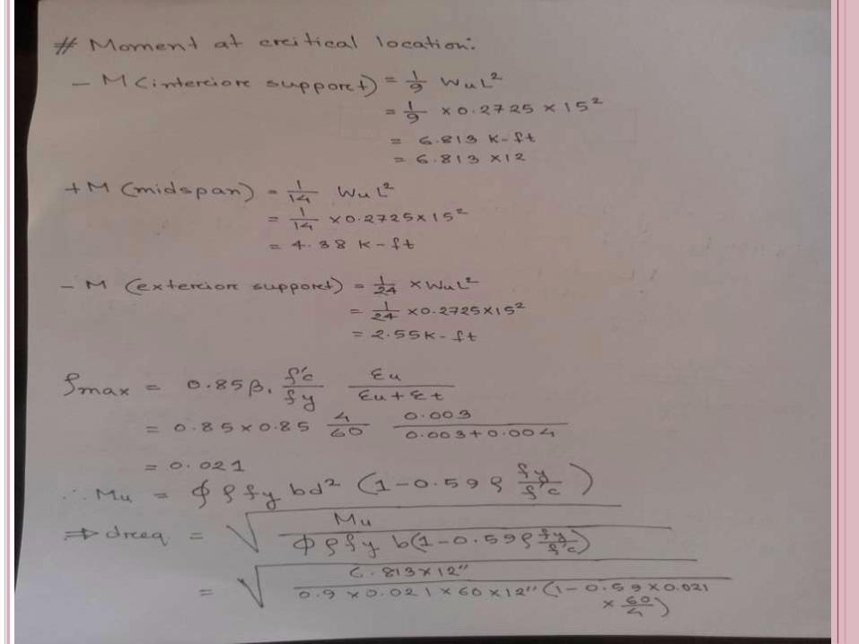
5- calculate maximum moment Mu.
6- Flexural reinforcement ratio is calculated from the following equation ,
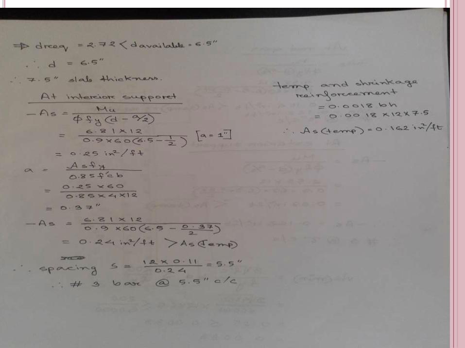
7-Compute the area of shrinkage reinforcement,
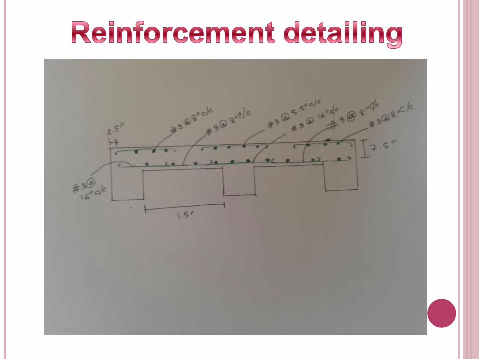
8-Draw a plan of the slab and representative cross sections showing the dimensions and the selected reinforcement.
εtεu
εu
f
'fβ0.85ρ
y
c1max