one piece ball valve - rory cu bila, ventile si armaturi.pdf · 3.7 one piece ball valve reduced...
TRANSCRIPT

3.5
SW
A
H
L
dG
One Piece Ball ValveInvestment casting, hexagon, reduced bore, with lever
With BSPP thread to ISO 228
DN G SW d L H A -No.
8 G 1/4" 17,5 5,0 46,5 30 62 300 HEX G 14-5i
10 G 3/8" 21,0 7,0 51,0 30 62 300 HEX G 38-5i
15 G 1/2" 25,0 9,2 64,0 45 92 300 HEX G 12-5i
20 G 3/4" 32,0 12,5 64,0 50 94 300 HEX G 34-5i
25 G 1" 38,0 15,0 73,5 68 118 300 HEX G 1-5i
32 G 1 1/4" 48,0 20,0 88,0 71 137 300 HEX G 114-5i
40 G 1 1/2" 55,0 25,0 96,0 75 137 300 HEX G 112-5i
50 G 2" 68,0 32,0 108,0 80 151 300 HEX G 2-5i
L Housing and Ball: AISI 316
Seal: PTFE
Depth for tap to DIN 3852 Part 2 Form A
We reserve the right to alter dimensions
300
HEX G
80
70
60
50
40
30
20
10
500°F4003002001000
0 50 100 150 200 250°C
200
400
600
800
1000
1200
Temperatur
Druck Temperatur Diagramm
Dru
ck P
SI
Dru
ck b
ar
Pressure-Temperature Chart
Temperature
Pre
ssu
re P
SI
Pre
ssu
re b
ar

3.6
One Piece Ball ValveInvestment casting, hexagon, reduced bore, butterfly handle
With BSPP thread to ISO 228
SW
L
H
dG
DN G SW d L H -No.
8 G 1/4" 17,5 5,0 46,5 38 301 HEX G 14-5i
10 G 3/8" 21,0 7,0 51,0 40 301 HEX G 38-5i
15 G 1/2" 25,0 9,2 64,0 47 301 HEX G 12-5i
L Housing and Ball: AISI 316
Seal: PTFE
Depth for tap to DIN 3852 Part 2 Form A
We reserve the right to alter dimensions
With Hose adaptor on request.
301
HEX G
80
70
60
50
40
30
20
10
500°F4003002001000
0 50 100 150 200 250°C
200
400
600
800
1000
1200
Temperatur
Druck Temperatur Diagramm
Dru
ck P
SI
Dru
ck b
ar
Pressure-Temperature Chart
Temperature
Pre
ssu
re P
SI
Pre
ssu
re b
ar
3.7
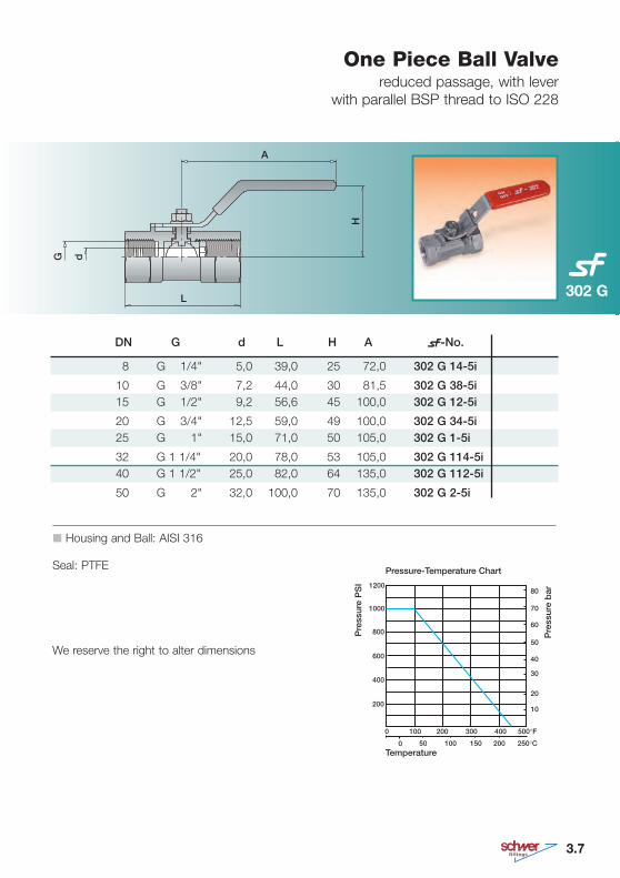
One Piece Ball Valvereduced passage, with lever
with parallel BSP thread to ISO 228
302 G
A
L
G d
H
DN G d L H A -No.
8 G 1/4" 5,0 39,0 25 72,0 302 G 14-5i
10 G 3/8" 7,2 44,0 30 81,5 302 G 38-5i
15 G 1/2" 9,2 56,6 45 100,0 302 G 12-5i
20 G 3/4" 12,5 59,0 49 100,0 302 G 34-5i
25 G 1" 15,0 71,0 50 105,0 302 G 1-5i
32 G 1 1/4" 20,0 78,0 53 105,0 302 G 114-5i
40 G 1 1/2" 25,0 82,0 64 135,0 302 G 112-5i
50 G 2" 32,0 100,0 70 135,0 302 G 2-5i
L Housing and Ball: AISI 316
Seal: PTFE
We reserve the right to alter dimensions
80
70
60
50
40
30
20
10
500°F4003002001000
0 50 100 150 200 250°C
200
400
600
800
1000
1200
Temperatur
Druck Temperatur Diagramm
Dru
ck P
SI
Dru
ck b
ar
Pressure-Temperature Chart
Temperature
Pre
ssu
re P
SI
Pre
ssu
re b
ar
3.8
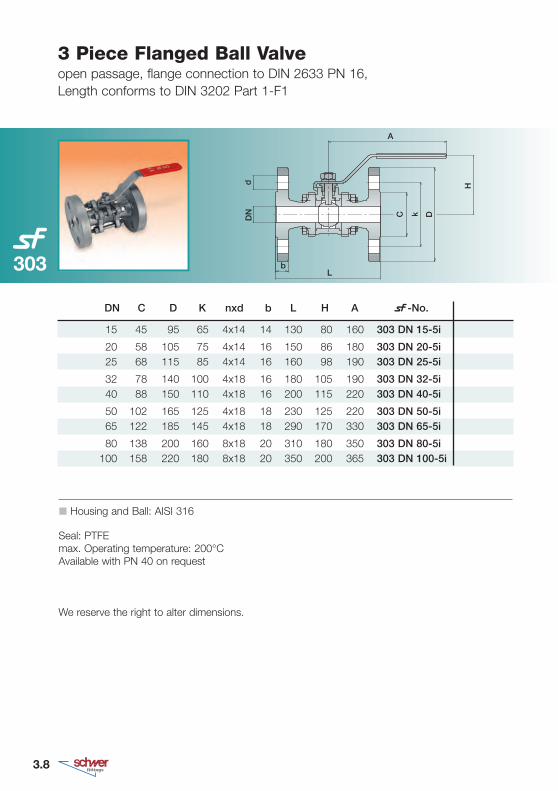
DN C D K nxd b L H A -No.
15 45 95 65 4x14 14 130 80 160 303 DN 15-5i
20 58 105 75 4x14 16 150 86 180 303 DN 20-5i
25 68 115 85 4x14 16 160 98 190 303 DN 25-5i
32 78 140 100 4x18 16 180 105 190 303 DN 32-5i
40 88 150 110 4x18 16 200 115 220 303 DN 40-5i
50 102 165 125 4x18 18 230 125 220 303 DN 50-5i
65 122 185 145 4x18 18 290 170 330 303 DN 65-5i
80 138 200 160 8x18 20 310 180 350 303 DN 80-5i
100 158 220 180 8x18 20 350 200 365 303 DN 100-5i
3 Piece Flanged Ball Valveopen passage, flange connection to DIN 2633 PN 16,
Length conforms to DIN 3202 Part 1-F1
303
A
L
C
b
DN
d
k D
H
L Housing and Ball: AISI 316
Seal: PTFE
max. Operating temperature: 200°C
Available with PN 40 on request
We reserve the right to alter dimensions.
3.9
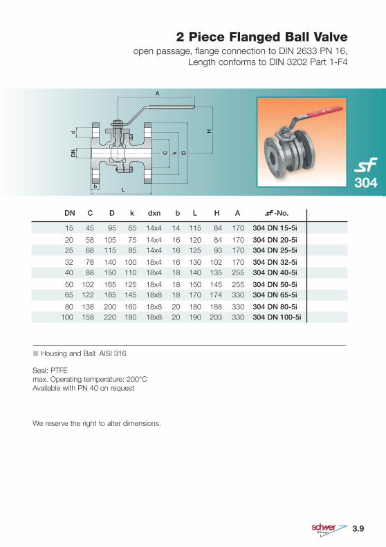
2 Piece Flanged Ball Valveopen passage, flange connection to DIN 2633 PN 16,
Length conforms to DIN 3202 Part 1-F4
304
A
L
C
b
DN
d
k D
HDN C D k dxn b L H A -No.
15 45 95 65 14x4 14 115 84 170 304 DN 15-5i
20 58 105 75 14x4 16 120 84 170 304 DN 20-5i
25 68 115 85 14x4 16 125 93 170 304 DN 25-5i
32 78 140 100 18x4 16 130 102 170 304 DN 32-5i
40 88 150 110 18x4 18 140 135 255 304 DN 40-5i
50 102 165 125 18x4 18 150 145 255 304 DN 50-5i
65 122 185 145 18x8 18 170 174 330 304 DN 65-5i
80 138 200 160 18x8 20 180 188 330 304 DN 80-5i
100 158 220 180 18x8 20 190 203 330 304 DN 100-5i
L Housing and Ball: AISI 316
Seal: PTFE
max. Operating temperature: 200°C
Available with PN 40 on request
We reserve the right to alter dimensions.

3.10
3 Piece Ball Valveopen passage,
with parallel BSP thread to ISO 228
306 G
A
H
L
G d
DN G d L H A -No.
8 G 1/4" 11,6 65,0 51,0 103 306 G 14-5i
10 G 3/8" 12,7 65,0 51,0 103 306 G 38-5i
15 G 1/2" 15,0 72,0 54,0 103 306 G 12-5i
20 G 3/4" 20,0 85,0 57,0 125 306 G 34-5i
25 G 1" 25,4 91,9 66,0 145 306 G 1-5i
32 G 1 1/4" 32,0 110,0 72,0 145 306 G 114-5i
40 G 1 1/2" 38,0 122,7 81,5 190 306 G 112-5i
50 G 2" 50,8 141,7 90,5 190 306 G 2-5i
65 G 2 1/2" 65,0 173,8 138,5 250 306 G 212-5i
80 G 3" 76,0 192,7 149,0 250 306 G 3-5i
100 G 4" 100,0 274,1 176,5 288 306 G 4-5i
L Housing and Ball: AISI 316
Seal: PTFE
Depth for tap to DIN 3852 Part 2 Form A
We reserve the right to alter dimensions.
80
70
60
50
40
30
20
10
500°F4003002001000
0 50 100 150 200 250°C
200
400
600
800
1000
1200
Temperatur
Druck Temperatur Diagramm
Dru
ck P
SI
Dru
ck b
ar
Pressure-Temperature Chart
Temperature
Pre
ssu
re P
SI
Pre
ssu
re b
ar

3.11
3 Piece Ball Valveopen passage,
with welding ends
307
dd1
H
L
A
D D1
DN D D1 d d1 L H A -No.
8 13,6 18 11,6 11,6 64,0 51,0 103 307 DN 8-5i
10 15,9 18 12,7 13,9 64,0 51,0 103 307 DN 10-5i
15 17,8 22 15,0 15,8 71,8 54,0 103 307 DN 15-5i
20 23,2 28 20,0 20,8 84,8 57,0 125 307 DN 20-5i
25 30,3 34 25,4 26,7 91,9 66,0 145 307 DN 25-5i
32 38,7 43 32,0 35,1 110,0 72,0 145 307 DN 32-5i
40 44,5 50 38,0 40,9 122,7 81,5 190 307 DN 40-5i
50 56,2 61 50,8 52,6 141,7 90,5 190 307 DN 50-5i
65 69,9 78 65,0 65,5 173,8 138,5 250 307 DN 65-5i
80 82,4 93 76,0 78,0 192,7 149,0 250 307 DN 80-5i
100 114,5 120 100,0 102,3 273,6 176,5 288 307 DN 100-5i
L Housing and Ball: AISI 316
Seal: PTFE
Depth for tap to DIN 3852 Part 2 Form A
For Orbital-Welding on request.
We reserve the right to alter dimensions.
80
70
60
50
40
30
20
10
500°F4003002001000
0 50 100 150 200 250°C
200
400
600
800
1000
1200
Temperatur
Druck Temperatur Diagramm
Dru
ck P
SI
Dru
ck b
ar
Pressure-Temperature Chart
Temperature
Pre
ssu
re P
SI
Pre
ssu
re b
ar
3.12
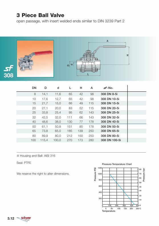
3 Piece Ball Valveopen passage, with insert welded ends similar to DIN 3239 Part 2
308
A
L
H
D d
DN D d L H A -No.
8 14,1 11,6 65 42 98 308 DN 8-5i
10 17,6 12,7 65 42 98 308 DN 10-5i
15 21,7 15,0 66 49 115 308 DN 15-5i
20 27,1 20,0 83 52 115 308 DN 20-5i
25 33,8 25,4 95 62 143 308 DN 25-5i
32 42,5 32,0 111 66 143 308 DN 32-5i
40 48,6 38,0 130 77 178 308 DN 40-5i
50 61,1 50,8 151 85 178 308 DN 50-5i
65 73,8 65,0 185 139 250 308 DN 65-5i
80 89,9 80,0 212 150 250 308 DN 80-5i
100 115,4 100,0 270 173 280 308 DN 100-5i
L Housing and Ball: AISI 316
Seal: PTFE
We reserve the right to alter dimensions.
80
70
60
50
40
30
20
10
500°F4003002001000
0 50 100 150 200 250°C
200
400
600
800
1000
1200
Temperatur
Druck Temperatur Diagramm
Dru
ck P
SI
Dru
ck b
ar
Pressure-Temperature Chart
Temperature
Pre
ssu
re P
SI
Pre
ssu
re b
ar

3.13
3 Piece Ball Valvesanitary fitting, with welding ends
309
A
H
Ll1
D d
DN D d L l1 A H -No.
10 13,0 10 81,0 20 103 51,0 309 1315-5i
15 19,0 16 84,2 20 103 54,0 309 1915-5i
20 23,0 20 95,0 20 125 57,0 309 2315-5i
25 29,0 26 102,7 20 145 66,0 309 2915-5i
32 35,0 32 112,8 20 145 72,0 309 3515-5i
40 41,0 38 125,7 20 190 81,5 309 4115-5i
L Housing and Ball: AISI 316
Seal: PTFE
Also available with BSP inside thread.
We reserve the right to alter dimensions.
80
70
60
50
40
30
20
10
500°F4003002001000
0 50 100 150 200 250°C
200
400
600
800
1000
1200
Temperatur
Druck Temperatur Diagramm
Dru
ck P
SI
Dru
ck b
ar
Pressure-Temperature Chart
Temperature
Pre
ssu
re P
SI
Pre
ssu
re b
ar

3.14
330
High Pressure Shut Off Valvewith compression ends to DIN 2353
DL
H
PN D L H -No.
6 80 100 330 6 L
250 8 80 100 330 8 L
10 80 100 330 10 L
12 80 100 330 12 L
15 81 100 330 15 L
18 107 115 330 18 L
160 22 147 125 330 22 L
28 148 125 330 28 L
6 80 100 330 6 S
400 8 80 100 330 8 S
10 82 100 330 10 S
12 82 100 330 12 S
14 84 100 330 14 S
16 109 115 330 16 S
20 152 125 330 20 S
25 154 125 330 25 S
L
S
Pressure Reduction Table
Temperature PB
to 75°C 400 bar
150°C 350 bar
225°C 300 bar
max. 250°C 280 bar
On request special design up to 500°C.
L Material: AISI 316TiSeal: PTFE, on request Graphite
Handwheel: Pressed
This valve can be also cupplied with
• female thread G, M, NPT
• male thread G, M, NPT
• weld nipple 24º
3.15
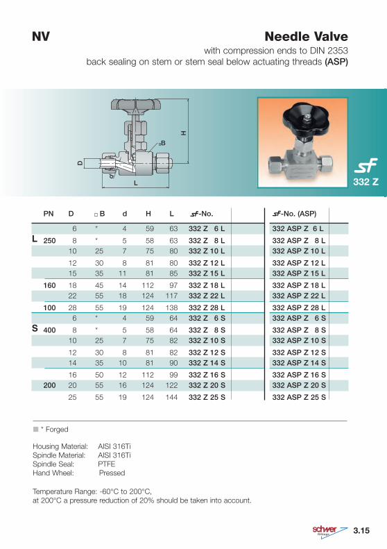
332 Z
PN D B d H L -No. -No. (ASP)
6 * 4 59 63 332 Z 6 L 332 ASP Z 6 L
250 8 * 5 58 63 332 Z 8 L 332 ASP Z 8 L
10 25 7 75 80 332 Z 10 L 332 ASP Z 10 L
12 30 8 81 80 332 Z 12 L 332 ASP Z 12 L
15 35 11 81 85 332 Z 15 L 332 ASP Z 15 L
160 18 45 14 112 97 332 Z 18 L 332 ASP Z 18 L
22 55 18 124 117 332 Z 22 L 332 ASP Z 22 L
100 28 55 19 124 138 332 Z 28 L 332 ASP Z 28 L
6 * 4 59 64 332 Z 6 S 332 ASP Z 6 S
400 8 * 5 58 64 332 Z 8 S 332 ASP Z 8 S
10 25 7 75 82 332 Z 10 S 332 ASP Z 10 S
12 30 8 81 82 332 Z 12 S 332 ASP Z 12 S
14 35 10 81 90 332 Z 14 S 332 ASP Z 14 S
16 50 12 112 99 332 Z 16 S 332 ASP Z 16 S
200 20 55 16 124 122 332 Z 20 S 332 ASP Z 20 S
25 55 19 124 144 332 Z 25 S 332 ASP Z 25 S
NV Needle Valvewith compression ends to DIN 2353
back sealing on stem or stem seal below actuating threads (ASP)
D
LH
B
d
L
S
Temperature Range: -60°C to 200°C,
at 200°C a pressure reduction of 20% should be taken into account.
L * Forged
Housing Material: AISI 316Ti
Spindle Material: AISI 316Ti
Spindle Seal: PTFE
Hand Wheel: Pressed

3.16
332 GG
L
H
i
d
B
Needle Valve NVwith parallel BSP thread to ISO 228
back sealing on stem or stem seal below actuating threads (ASP)
also available with NPT inside thread
PN G i B d H L -No. -No. (ASP)
250 G 1/8" 8,5 * 4 60 43 332 G 18
400 G 1/4" 11,0 25 5 74 50 332 G 14 332 ASP G 14
G 3/8" 12,5 25 6 74 55 332 G 38 332 ASP G 38
G 1/2" 14,5 30 8 82 60 332 G 12 332 ASP G 12
G 3/4" 16,5 35 10 82 75 332 G 34 332 ASP G 34
G 1" 20,0 50 14 115 100 332 G 1 332 ASP G 1
G 1 1/4" 21,0 60 16 125 110 332 G 114 332 ASP G 114
200 G 1 1/2" 22,0 60 19 125 130 332 G 112 332 ASP G 112
G 2" 27,0 70 22 135 150 332 G 2 332 ASP G 2
L * Forged
Housing Material: AISI 316Ti
Spindle Material: AISI 316Ti
Spindle Seal: PTFE
Hand Wheel: Pressed
also available with NPT inside thread
Temperature Range: -60°C to 200°C,
at 200°C a pressure reduction of 20% should be taken into account.
3.17
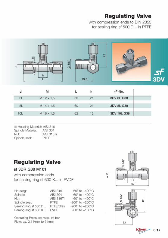
Regulating Valve
sf 3DR G38 M101
with compression ends
for sealing ring sf 600 K... in PVDF
Regulating Valvewith compression ends to DIN 2353
for sealing ring sf 500 D... in PTFE
3DVL
l1
29,5
42
G 3
/8"
M
d
60
17
G 3
/8"
ø 1
0
32
42M 1
0x1
d M L l1 -No.
6L M 12 x 1,5 60 21 3DV 6L G38
8L M 14 x 1,5 60 21 3DV 8L G38
10L M 16 x 1,5 62 15 3DV 10L G38
L Housing Material: AISI 316Spindle Material: AISI 304
Nut: AISI 316Ti
Spindle seal: PTFE
Housing: AISI 316 -60° to +400°C
Spindle: AISI 304 -60° to +400°C
Nut: AISI 316Ti -60° to +400°C
Spindle seal: PTFE -200° to +200°C
Sealing ring sf 500 D... PTFE/Glas -200° to +200°C
Sealing ring sf 600 K... PVDF -60° to +150°C
Operating Pressure: max. 16 bar
Flow: ca. 0,1 l/min to 5 l/min

3.18
Short Flanged Ball ValveOne piece housing, short body, open passage,
with flange connection to ISO 2501 PN16,
with flange connection for actuator to ISO 5211
336
A
H
DdM
k
L
B
DN d D k M L H A -No.
15 15 95 65 M12 40 70 150 336 DN 15 5211-5i
20 20 105 75 M12 44 75 150 336 DN 20 5211-5i
25 25 115 85 M12 53 78 180 336 DN 25 5211-5i
32 32 135 100 M16 58 84 180 336 DN 32 5211-5i
40 40 145 110 M16 62 94 200 336 DN 40 5211-5i
50 50 155 125 M16 72 100 200 336 DN 50 5211-5i
65 65 185 145 M16 94 135 250 336 DN 65 5211-5i
80 80 200 160 M16 118 152 285 336 DN 80 5211-5i
100 100 220 180 M16 140 170 335 336 DN 100 5211-5i
L Housing and Ball Material: AISI 316
Seal Material: PTFE
Temperature Range: -50°C to 200°C
We reserve the right to alter dimensions.
3.19
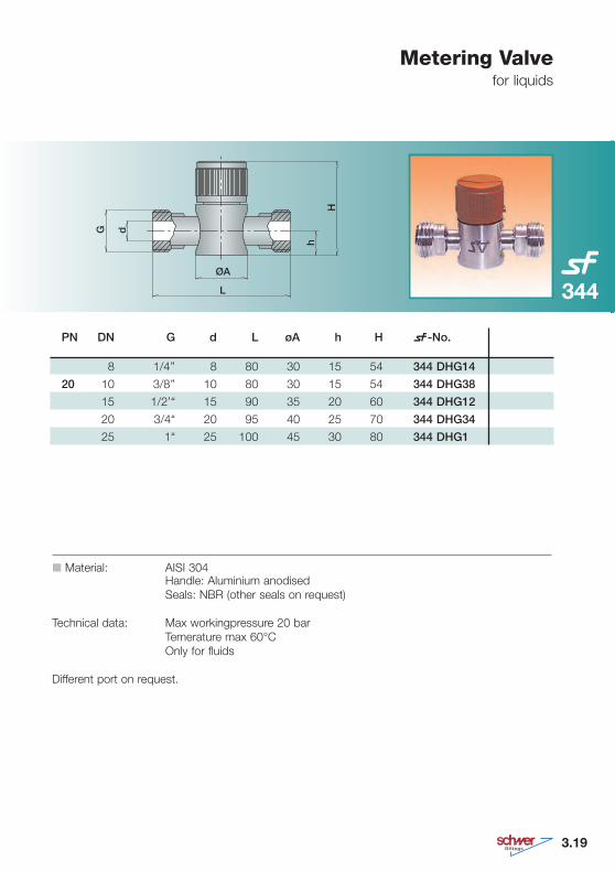
344
G d
h
H
ØA
L
PN DN G d L øA h H -No.
8 1/4’’ 8 80 30 15 54 344 DHG14
20 10 3/8’’ 10 80 30 15 54 344 DHG38
15 1/2’“ 15 90 35 20 60 344 DHG12
20 3/4“ 20 95 40 25 70 344 DHG34
25 1“ 25 100 45 30 80 344 DHG1
L Material: AISI 304Handle: Aluminium anodised
Seals: NBR (other seals on request)
Technical data: Max workingpressure 20 bar
Temerature max 60°C
Only for fluids
Different port on request.
Metering Valvefor liquids

3.20
H
dD
L
Mini-Compact Ball Valvewith compression ends to DIN 2353 (as shown below)
or with parallel BSP thread to ISO 228
or with NPT inside thread to ANSI/ASME B 1.20.1 - 1983
Mini-Compact ball valvewith compression endsPN D d L H -No.
6L 4 52,0 25,0 350 6L-7
100 8L 4 52,0 25,0 350 8L-7
10L 7 64,5 39,5 350 10L-7
12L 8 64,5 39,5 350 12L-7
15L 11 76,5 41,0 350 15L-7
Mini-Compact ball valve with BSP threadPN Thread d L H -No.
G 1/8" 4 51,0 25,0 350 G18-7
100 G 1/4" 4 57,0 25,0 350 G14-7
G 3/8" 8 67,5 39,5 350 G38-7
G 1/2" 11 77,5 41,0 350 G12-7
Mini-Compact ball valve with NPT inside threadPN Thread d L H -No.
1/8" NPT 4 51,0 25,0 350 N18-7
100 1/4" NPT 4 55,0 25,0 350 N14-7
3/8" NPT 8 67,5 39,5 350 N38-7
1/2" NPT 11 77,5 41,0 350 N12-7
L Housing Material: AISI 316Ti,
Ball: AISI 316
Seal Material: PTFE
O-Ring: Perbunan (NBR), Viton on request
L
350
3.21
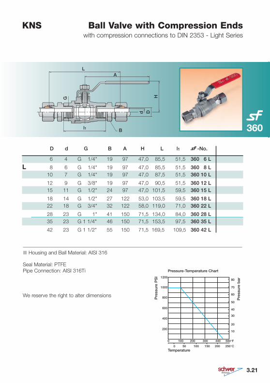
360
d
GL
A
Bl1
H
D
KNS Ball Valve with Compression Endswith compression connections to DIN 2353 - Light Series
D d G B A H L l1 -No.
6 4 G 1/4" 19 97 47,0 85,5 51,5 360 6 L
8 6 G 1/4" 19 97 47,0 85,5 51,5 360 8 L
10 7 G 1/4" 19 97 47,0 87,5 51,5 360 10 L
12 9 G 3/8" 19 97 47,0 90,5 51,5 360 12 L
15 11 G 1/2" 24 97 47,0 101,5 59,5 360 15 L
18 14 G 1/2" 27 122 53,0 103,5 59,5 360 18 L
22 18 G 3/4" 32 122 58,0 119,0 71,0 360 22 L
28 23 G 1" 41 150 71,5 134,0 84,0 360 28 L
35 23 G 1 1/4" 46 150 71,5 153,5 97,5 360 35 L
42 23 G 1 1/2" 55 150 71,5 169,5 109,5 360 42 L
L
L Housing and Ball Material: AISI 316
Seal Material: PTFE
Pipe Connection: AISI 316Ti
We reserve the right to alter dimensions
80
70
60
50
40
30
20
10
500°F4003002001000
0 50 100 150 200 250°C
200
400
600
800
1000
1200
Temperatur
Druck Temperatur Diagramm
Dru
ck P
SI
Dru
ck b
ar
Pressure-Temperature Chart
Temperature
Pre
ssu
re P
SI
Pre
ssu
re b
ar

3.22
360 G
A
L
H
G d
2-piece Ball Valveopen passage, with parallel BSP thread to ISO 228
L Housing and Ball Material: AISI 316
Seal Material: PTFE
Depth for tap to DIN 3852 Part 2 Form A
We reserve the right to alter dimensions
80
70
60
50
40
30
20
10
500°F4003002001000
0 50 100 150 200 250°C
200
400
600
800
1000
1200
Temperatur
Druck Temperatur Diagramm
Dru
ck P
SI
Dru
ck b
ar
Pressure-Temperature Chart
Temperature
Pre
ssu
re P
SI
Pre
ssu
re b
ar
DN G d L H A -No.
8 G 1/4" 11,6 50,0 46,0 102 360 G14-5i
10 G 3/8" 12,7 52,0 46,0 102 360 G38-5i
15 G 1/2" 15,0 60,0 48,0 102 360 G12-5i
20 G 3/4" 20,0 77,0 52,0 127 360 G34-5i
25 G 1" 25,4 87,0 62,0 146 360 G1-5i
32 G 1 1/4" 32,0 97,0 65,0 146 360 G114-5i
40 G 1 1/2" 38,0 110,0 75,0 191 360 G112-5i
50 G 2" 50,8 134,0 82,0 191 360 G2-5i
65 G 2 1/2" 65,0 167,0 127,0 247 360 G212-5i
80 G 3" 76,0 192,0 137,0 247 360 G3-5i
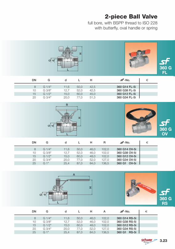
3.23
360 G
FL
2-piece Ball Valvefull bore, with BSPP thread to ISO 228
with butterfly, oval handle or spring
dG
H
L
DN G d L H -No. €
8 G 1/4" 11,6 50,0 42,5 360 G14 FL-5i
10 G 3/8" 12,7 52,0 42,5 360 G38 FL-5i
15 G 1/2" 15,0 60,0 45,0 360 G12 FL-5i
20 G 3/4" 20,0 77,0 51,3 360 G34 FL-5i
DN G d L H R -No. €
8 G 1/4" 11,6 50,0 46,0 102,0 360 G14 OV-5i
10 G 3/8" 12,7 52,0 46,0 102,0 360 G38 OV-5i
15 G 1/2" 15,0 60,0 48,0 102,0 360 G12 OV-5i
20 G 3/4" 20,0 77,0 52,0 127,0 360 G34 OV-5i
25 G 1" 25,4 87,0 84,0 136,5 360 G1 OV-5i
360 G
OV
DN G d L H A -No. €
8 G 1/4" 11,6 50,0 46,0 102,0 360 G14 RS-5i
10 G 3/8" 12,7 52,0 46,0 102,0 360 G38 RS-5i
15 G 1/2" 15,0 60,0 48,0 102,0 360 G12 RS-5i
20 G 3/4" 20,0 77,0 52,0 127,0 360 G34 RS-5i
25 G 1" 25,4 87,0 84,0 136,5 360 G1 RS-5i
360 G
RS
dG
H
L
R
A
H
G d
L

3.24
363 G
A
L
H
G d
3-Way Ball Valvewith L or T Bore, 360° Switching
with parallel BSP thread to ISO 228
DN G d L H A -No.
08 G 1/4" 11,5 60 56 95 363 G14 L-5i
10 G 3/8" 12,8 60 56 95 363 G38 L-5i
15 G 1/2" 12,7 64 56 95 363 G12 L-5i
20 G 3/4" 16,0 76 64 125 363 G34 L-5i
25 G 1" 20,0 82 66 125 363 G1 L-5i
32 G 1 1/4" 25,0 97 70 145 363 G114 L-5i
40 G 1 1/2" 32,2 114 83 145 363 G112 L-5i
50 G 2" 38,2 142 88 205 363 G2 L-5i
L Housing and Ball Material: AISI 316
Seal Material: PTFE
L bore is standard
Available with T bore on request
Order example:
sf 363 G12 T-5i
We reserve the right to alter dimensions
1
2 3
1
2 3
L
T
Switching Diagram
80
70
60
50
40
30
20
10
500°F4003002001000
0 50 100 150 200 250°C
200
400
600
800
1000
1200
Temperatur
Druck Temperatur Diagramm
Dru
ck P
SI
Dru
ck b
ar
Pressure-Temperature Chart
Temperature
Pre
ssu
re P
SI
Pre
ssu
re b
ar
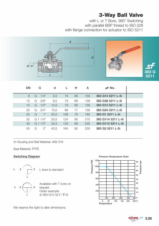
3.25
363 G
5211
H
dG
L
A
3-Way Ball Valvewith L or T Bore, 360° Switching
with parallel BSP thread to ISO 228
with flange connection for actuator to ISO 5211
DN G d L H A -No.
8 G 1/4" 9,5 79 66 158 363 G14 5211 L-5i
10 G 3/8" 9,5 79 66 158 363 G38 5211 L-5i
15 G 1/2“ 12,0 79 66 158 363 G12 5211 L-5i
20 G 3/4" 15,0 88 77 158 363 G34 5211 L-5i
25 G 1" 20,0 108 78 185 363 G1 5211 L-5i
32 G 1 1/4" 25,0 124 90 210 363 G114 5211 L-5i
40 G 1 1/2" 32,0 135 98 235 363 G112 5211 L-5i
50 G 2" 40,0 164 92 235 363 G2 5211 L-5i
L Housing and Ball Material: AISI 316
Seal Material: PTFE
L bore is standard
Available with T bore on
request
Order example:
sf 363 G12 5211 T-5i
We reserve the right to alter dimensions.
1
2 3
1
2 3
L
T
Switching Diagram
80
70
60
50
40
30
20
10
500°F4003002001000
0 50 100 150 200 250°C
200
400
600
800
1000
1200
Temperatur
Druck Temperatur Diagramm
Dru
ck P
SI
Dru
ck b
ar
Pressure-Temperature Chart
Temperature
Pre
ssu
re P
SI
Pre
ssu
re b
ar
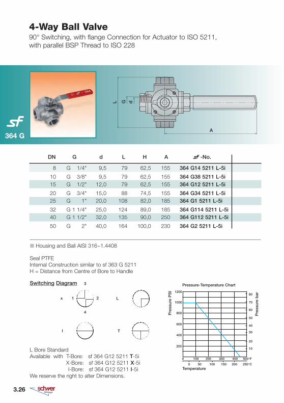
3.26
364 GdGL
A
4-Way Ball Valve90° Switching, with flange Connection for Actuator to ISO 5211,
with parallel BSP Thread to ISO 228
DN G d L H A -No.
8 G 1/4" 9,5 79 62,5 155 364 G14 5211 L-5i
10 G 3/8" 9,5 79 62,5 155 364 G38 5211 L-5i
15 G 1/2" 12,0 79 62,5 155 364 G12 5211 L-5i
20 G 3/4" 15,0 88 74,5 155 364 G34 5211 L-5i
25 G 1" 20,0 108 82,0 185 364 G1 5211 L-5i
32 G 1 1/4" 25,0 124 89,0 185 364 G114 5211 L-5i
40 G 1 1/2" 32,0 135 90,0 250 364 G112 5211 L-5i
50 G 2" 40,0 164 100,0 230 364 G2 5211 L-5i
L Housing and Ball AISI 316~1.4408
Seal PTFE
Internal Construction similar to sf 363 G 5211
H = Distance from Centre of Bore to Handle
L Bore Standard
Available with T-Bore: sf 364 G12 5211 T-5i
X-Bore: sf 364 G12 5211 X-5i
I-Bore: sf 364 G12 5211 I-5i
We reserve the right to alter Dimensions.
4
3
1 2x
I
L
T
Switching Diagram
80
70
60
50
40
30
20
10
500°F4003002001000
0 50 100 150 200 250°C
200
400
600
800
1000
1200
Temperatur
Druck Temperatur Diagramm
Dru
ck P
SI
Dru
ck b
ar
Pressure-Temperature Chart
Temperature
Pre
ssu
re P
SI
Pre
ssu
re b
ar

3.27
365 G
G
L
A
H
Shut off ValvesInclined Position, Length to DIN 3202
with parallel BSP Thread to ISO 228
PN DN G L H A -No.
8 G 1/4" 65 100 63 365 G14-5i
16 10 G 3/8" 65 100 63 365 G38-5i
15 G 1/2" 65 100 63 365 G12-5i
20 G 3/4" 75 125 75 365 G34-5i
25 G 1" 90 130 75 365 G1-5i
32 G 1 1/4" 110 165 100 365 G114-5i
40 G 1 1/2" 120 170 100 365 G112-5i
50 G 2" 150 210 100 365 G2-5i
L Housing AISI 316~1.4408
Seal PTFE
max. operating temperature 230° C
We reserve the right to alter dimensions.
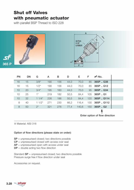
3.28
365 P
Shut off Valves
with pneumatic actuatorwith parallel BSP Thread to ISO 228
Air-PortsG 1/8"to NAMUR
G
F
B
D
A
Ø E
PN DN G A B D E F -No.
16 15 3/8“ 190 156 44,0 70,0 85 365P .. G38
16 15 1/2“ 190 156 44,0 70,0 85 365P .. G12
10 20 3/4“ 195 160 44,0 70,0 95 365P .. G34
10 25 1“ 219 182 50,5 84,4 105 365P .. G1
10 32 1 1/4“ 226 186 50,5 84,4 120 365P .. G114
8 40 1 1/2“ 271 230 66,2 116,4 130 365P .. G112
8 50 2“ 321 276 77,4 140,6 150 365P .. G2
L Material: AISI 316
Option of flow directions (please state on order):
SP = unpressurised closed; two directions possible
CP = unpressurised closed with access over seal
AP = unpressurised open with access under seal
DP = double acting two flow direction
Standard SP = unpressurised closed; two directions possible
Pressure surge free if flow direction under seal
Accessories on request.
Enter option of flow direction

3.29
366 G
Globe ValveMetal Valve seat,
with parallel BSP thread to ISO 228
A
L
G
H
PN DN G L H A -No.
8 G 1/4" 52 102 60 366 G14-5i
16 10 G 3/8" 52 102 60 366 G38-5i
15 G 1/2" 52 102 60 366 G12-5i
20 G 3/4" 60 113 70 366 G34-5i
25 G 1" 72 123 70 366 G1-5i
32 G 1 1/4" 80 148 80 366 G114-5i
40 G 1 1/2" 90 160 90 366 G112-5i
50 G 2" 106 180 100 366 G2-5i
L Housing: AISI 316~1.4408
Seal: PTFE
max. operating temperature 180° C
We reserve the right to alter dimensions.
3.30
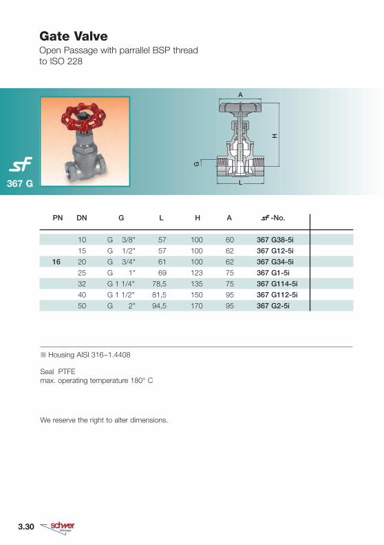
367 G
Gate ValveOpen Passage with parrallel BSP thread
to ISO 228
A
L
G
H
PN DN G L H A -No.
10 G 3/8" 57 100 60 367 G38-5i
15 G 1/2" 57 100 62 367 G12-5i
16 20 G 3/4" 61 100 62 367 G34-5i
25 G 1" 69 123 75 367 G1-5i
32 G 1 1/4" 78,5 135 75 367 G114-5i
40 G 1 1/2" 81,5 150 95 367 G112-5i
50 G 2" 94,5 170 95 367 G2-5i
L Housing AISI 316~1.4408
Seal PTFE
max. operating temperature 180° C
We reserve the right to alter dimensions.

3.31
PB DN G L H -No.
8 G 1/4" 57 30 371 G14-5i
42 10 G 3/8" 57 30 371 G38-5i
15 G 1/2" 61 34 371 G12-5i
20 G 3/4" 70 38 371 G34-5i
25 G 1" 88 42 371 G1-5i
32 G 1 1/4" 100 50 371 G114-5i
35 40 G 1 1/2" 111 57 371 G112-5i
50 G 2" 133 70 371 G2-5i
L Housing AISI 316~1.4408
Seal PTFE
max. operating temperature 180° C
We reserve the right to alter dimensions.
371 G
Return Check ValveWith parallel BSP theard to ISO 228
L
G
H

3.32
372 G
Flap Trapwith parallel BSP thread to ISO 228
Standard in upright from
L
G
H
PN DN G L H -No.
15 G 1/2" 65 45 372 G12-5i
16 20 G 3/4" 80 55 372 G34-5i
25 G 1" 90 58 372 G1-5i
32 G 1 1/4" 105 62 372 G114-5i
40 G 1 1/2" 120 75 372 G112-5i
50 G 2" 140 78 372 G2-5i
L Housing AISI 316~1.4408
Seal PTFE
max. operating temperature 180° C
Inclined availale on request.
We reserve the right to alter dimensions.
H
G
L
upright Iinclined

3.33
377G378
Mud Drainwith exchangeable inside strainer,
with parallel BSP thread to ISO 228
with flange connection to DIN 2633 PN 16
L
H
PN DN L H -No.
15 130 66 378 DN15-5i
16 20 150 78 378 DN20-5i
25 160 90 378 DN25-5i
32 180 119 378 DN32-5i
50 200 140 378 DN50-5i
40 180 118 378 DN40-5i
50 200 140 378 DN50-5i
65 270 178 378 DN65-5i
80 280 195 378 DN80-5i
100 300 240 378 DN100-5i
L Housing AISI 316-1.4408Seal PTFE, max. operating temperature 230° C
Standard Mesh 1,0 mm, 0,5 mm on request
Replarement filters available
Flange Connection to DIN 2633 PN 40 on request.
L
H
G
PB DN G L H -No.
8 G 1/4" 57 35 377 G14-5i
20 10 G 3/8" 57 35 377 G 38-5i
15 G 1/2" 60 38 377 G12-5i
20 G 3/4" 69 42 377 G34-5i
25 G 1" 85 50 377 G1-5i
32 G 1 1/4" 99 55 377 G114-5i
40 G 1 1/2" 111 59 377 G112-5i
50 G 2" 137 73 377 G2-5i
65 G 2 1/2" 172 91 377 G212-5i
80 G 3" 205 110 377 G3-5i
We reserve the right to alter
dimensions.
with flange connectionwith thread
with parallel BSP thread to ISO 228
with flange connection to DIN 2633 PN 16
3.34
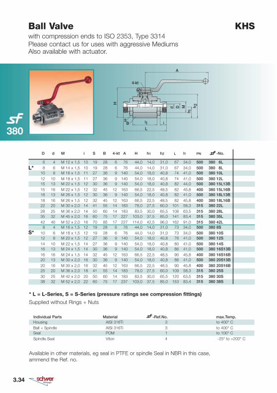
380
Individual Parts Material -Ref.No. max.Temp.
Housing AISI 316Ti 3 to 400° C
Ball + Spindle AISI 316Ti 3 to 400° C
Seal POM 1 to 100° C
Spindle Seal Viton 4 -25° to +200° C
Available in other materials, eg seal in PTFE or spindle Seal in NBR in this case,
ammend the Ref. no.
Ball Valve KHSwith compression ends to ISO 2353, Type 3314
Please contact us for uses with aggressive MediumsAlso available with actuator.
H
A
1 il
L
2
1
h
h
MDd
B
4-kt
S
D d M i S B 4-kt A H h1 h2 L l1 PN -No.
6 4 M 12 x 1,5 10 19 28 6 76 44,0 14,0 31,0 67 34,0 500 380 6L
8 6 M 14 x 1,5 10 19 28 6 76 44,0 14,0 31,0 67 34,0 500 380 8L
10 8 M 16 x 1,5 11 27 36 9 140 54,0 18,0 40,8 74 41,0 500 380 10L
12 10 M 18 x 1,5 11 27 36 9 140 54,0 18,0 40,8 74 41,0 500 380 12L
15 13 M 22 x 1,5 12 30 36 9 140 54,0 18,0 40,8 82 44,0 500 380 15L13B
15 16 M 22 x 1,5 12 32 45 12 163 66,5 22,5 48,5 82 45,8 400 380 15L16B
18 13 M 26 x 1,5 12 30 36 9 140 54,0 18,0 40,8 82 41,0 500 380 18L13B
18 16 M 26 x 1,5 12 32 45 12 163 66,5 22,5 48,5 82 45,8 400 380 18L16B
22 20 M 30 x 2,0 14 41 55 14 183 78,0 27,5 60,0 101 58,3 315 380 22L
28 25 M 36 x 2,0 14 50 60 14 183 83,5 30,0 65,5 108 63,5 315 380 28L
35 32 M 45 x 2,0 16 60 75 17 227 103,0 37,5 85,0 141 83,4 315 380 35L
42 40 M 52 x 2,0 16 70 85 17 227 114,0 42,5 96,0 162 91,0 315 380 42L
8 4 M 16 x 1,5 12 19 28 6 76 44,0 14,0 31,0 73 34,0 500 380 8S
10 6 M 18 x 1,5 12 19 28 6 76 44,0 14,0 31,0 73 34,0 500 380 10S
12 8 M 20 x 1,5 12 27 36 9 140 54,0 18,0 40,8 76 41,0 500 380 12S
14 10 M 22 x 1,5 14 27 36 9 140 54,0 18,0 40,8 80 41,0 500 380 14S
16 13 M 24 x 1,5 14 30 36 9 140 54,0 18,0 40,8 86 41,0 500 380 16S13B
16 16 M 24 x 1,5 14 32 45 12 163 66,5 22,5 48,5 90 45,8 400 380 16S16B
20 13 M 30 x 2,0 16 30 36 9 140 54,0 18,0 40,8 86 41,0 500 380 20S13B
20 16 M 30 x 2,0 16 32 45 12 163 66,5 22,5 48,5 90 45,8 400 380 20S16B
25 20 M 36 x 2,0 18 41 55 14 183 78,0 27,5 60,0 109 58,3 315 380 25S
30 25 M 42 x 2,0 20 50 60 14 183 83,5 30,0 65,5 120 63,5 315 380 30S
38 32 M 52 x 2,0 22 60 75 17 237 103,0 37,5 85,0 153 83,4 315 380 38S
S*
L*
* L = L-Series, S = S-Series (pressure ratings see compression fittings)
Supplied without Rings + Nuts

3.35
381
MKH Female Ball Valvewith parallel inside BSP thread to ISO 228
or with NPT-thread to ANSI/ASME B 1.20.1-1983, Type 3314Please contact us for uses with agressive Mediums
Also available with actuator.H
1
2h
1hG/N
PT
dil
L
A
B
4-kt
S
PN G/NPT i d S B 4-kt A H h1 h2 L l1 -No.
G 1/8" 10,0 4 19 28 6 76 44,0 14,0 31,0 69 34,0 381G18
500 G 1/4" 14,0 6 22 28 6 76 44,0 14,0 31,0 69 34,0 381G14
G 3/8" 14,0 10 27 36 9 140 54,0 18,0 40,8 72 41,0 381G38
DIN/ G 1/2" 16,0 13 30 36 9 140 54,0 18,0 40,8 83 41,0 381G12B13
ISO 400 G 1/2" 16,0 16 32 45 12 163 66,5 22,5 48,5 83 45,8 381G12B16
228 G 3/4" 18,0 20 41 55 14 183 78,0 27,5 60,0 95 58,3 381G34
315 G 1" 20,5 25 50 60 14 183 83,5 30,0 65,5 113 63,5 381G1
G 1 1/4" 22,0 30 60 75 17 227 103,0 37,5 85,0 110 83,4 381G114
G 1 1/2" 24,0 38 70 85 17 227 114,0 42,5 96,0 130 91,0 381G112
G 2" 26,0 48 80 105 17 227 131,5 52,5 112,5 140 100,0 381G2
1/8" NPT 13,0 4 24 29 9 150 51,5 14,5 36,5 69 34,0 381N18
500 1/4" NPT 13,0 6 24 29 9 150 51,5 14,5 36,5 69 34,0 381N14
3/8" NPT 13,0 10 27 38 9 150 57,0 19,0 42,0 72 41,0 381N38
1/2" NPT 16,5 13 32 45 12 175 66,0 22,5 48,5 83 46,0 381N12B13
400 1/2" NPT 16,5 16 32 45 12 175 66,0 22,5 48,5 83 46,0 381N12B16
3/4" NPT 17,0 20 41 55 14 200 79,0 27,5 60,0 95 58,5 381N34
1" NPT 20,5 25 50 60 14 200 84,0 30,0 65,5 113 63,5 381N1
315 1 1/4" NPT 25,0 30 60 75 17 240 104,5 37,5 85,0 110 63,4 381N114
1 1/2" NPT 27,0 38 70 85 17 240 115,0 42,5 96,0 130 91,0 381N112
2" NPT 27,0 48 80 105 17 240 132,5 52,5 12,5 140 100,0 381N2
NPT
G
Individual Parts Material -Ref. No. max.Temp.
Housing AISI 316Ti 3 to 400° C
Ball + Spindle AISI 316Ti 3 to 400° C
Seal POM 1 to 100° C
Spindle Seal Viton 4 -25° to +200° C
Available in other materials, eg seal in PTFE or spindle Seal in NBR in this case,
ammend the Ref. no.

3.36
385
3 Way Female Ball Valve UMKHwith parallel inside BSP thread to ISO 228, Type 3314
Also available with NPT connection.Also available with actuator.
4-kt
A
G
h1
h2
l
i
S
B
l
L
1
2
PN DN G i S B 4-kt A h1 h2 L l1 l2 -No.
4 G 1/8" 10 24 28 6 76 14,0 31,0 69 34,0 34,5 385 G 18 L
500 6 G 1/4" 14 24 28 6 76 14,0 31,0 69 34,0 34,5 385 G 14 L
10 G 3/8" 14 27 36 9 140 18,0 40,8 72 41,0 36,0 385 G 38 L
12 G 1/2" 16 32 36 9 140 18,0 40,8 83 41,0 41,5 385 G 12 L
400 16 G 1/2" 16 32 45 12 163 22,5 48,5 83 45,8 41,5 385 G 1216 L
315 20 G 3/4" 18 41 55 14 183 27,5 60,0 95 58,3 47,5 385 G 34 L
25 G 1" 20 50 60 14 183 30,0 65,5 113 63,5 56,5 385 G 1 L
L
Pressvre input only on connection 1.
Leakages are likely when connectes on 2 or 3.
L-Bore standard,
T- availabe on requst. eg. sf 385 G-12 T
Switching Diagramm
Position 1: Position 2: Position 3:
Switching Diagramm
L
1
2 3
1
2 3
T
1
2 3
1
2 3
1
2 3
L
T
Individual Parts Material -Ref. no. Max.Temp.
Housing AISI 316Ti 3 to 400° C
Ball + Spindle AISI 316Ti 3 to 400° C
Seal POM 1 to 100° C
Spindle Seal Viton 4 -25° to +200° C
Available in other materials, eg seal in PTFE or spindle Seal in NBR in this case,
ammend the Ref. no.

3.37
High Pressure Ball Valves
with Actuatorfemale thread or compression ends
396KHG KHS UKH UKHS
G
Lg
A
60
B30
H D
Ls
G
l2C Lg Ls
D
l2C
DN 04 06 10 13 16 20 25 32 40 50
Female thread (KHN=NPT)
Size G G1/8" G1/4” G3/8” G1/2” G1/2” G3/4” G1” G11/4” G11/2” G2” length Lg 69 69 72 83 83 95 113 110 130 140 A single acting 160 160 182 182 215 222 294 294 300 350B 100 100 108 108 117 140 140 140 160 198H 207 207 221 221 233 263 266 277 303 349A double acting 139 139 160 160 182 182 215 222 294 294B 88 88 100 100 108 108 117 140 140 140H 195 195 213 213 224 231 243 277 283 291
Compression ends
L Size D 6L 8L 10L 12L 15L 18L 22L 28L 35L 42Llength Ls 67 67 74 74 82 82 101 108 141 162
S Size D 6S 8S 10S 12S 14S 16S 20S 25S 30S 38Slength Ls 73 73 73 76 80 86 90 109 120 153
3-Way Ball Valve female thread (UKHN=NPT)
Size G G1/8” G1/4” G3/8” G1/2” G1/2” G3/4” G1” G11/4” G11/2” G2” length Lg 69 69 72 83 83 95 113 110 * * C 28 28 36 36 45 55 60 60 l2 34,5 34,5 36 41,5 41,5 47,5 56,5 60
3-Way Ball Valve Compression ends
L Size D 6L 8L 10L 12L 15L 18L 22L 28L 35L 42Llength Ls 67 67 74 74 82 82 101 108 * * C 25 25 32 32 38 38 48 57 l2 34,5 34,5 37 37 40 42 52 54
S Size D 6S 8S 10S 12S 14S 16S 20S 25S 30S 38Slength Ls * 73 73 76 80 86 90 109 120 *C 25 25 32 32 35 38 48 57l2 37 37 38 40 44 45,5 56 60
* on request
sf396 KHG12 3314 AP H D 3 Esf-group Port Size Material Actuator high-pressure single/double Valve Switch
KHG UKHG 1/2” Housing 3=1.4571 pneumatic to 500 bar D = double 3 = 3/2 Valve E = electric
KHN UKHN Ball 3=1.4571 E = single 5 = 5/2 Valve mechanical
KHS UKHS Seal 1=POM Temperature: I = inductiv
Spindle 4=Viton –25°C to +200°C
KHG
KHS
UKHG
UKHS
Type
3.38
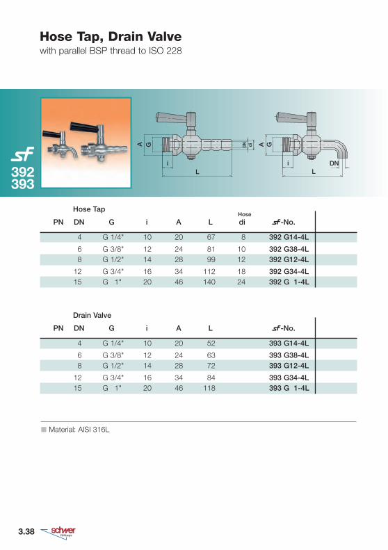
Hose Tap, Drain Valvewith parallel BSP thread to ISO 228
392393
G
LL
GA A
DNi i
DN di
Hose TapHose
PN DN G i A L di -No.
4 G 1/4" 10 20 67 8 392 G14-4L
6 G 3/8" 12 24 81 10 392 G38-4L
8 G 1/2" 14 28 99 12 392 G12-4L
12 G 3/4" 16 34 112 18 392 G34-4L
15 G 1" 20 46 140 24 392 G 1-4L
Drain Valve
PN DN G i A L -No.
4 G 1/4" 10 20 52 393 G14-4L
6 G 3/8" 12 24 63 393 G38-4L
8 G 1/2" 14 28 72 393 G12-4L
12 G 3/4" 16 34 84 393 G34-4L
15 G 1" 20 46 118 393 G 1-4L
L Material: AISI 316L
3.39
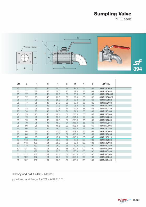
DN L H R F d D h b -No.
25 77 95 146 25,0 29 43,0 65 65 394P25D043
25 77 95 146 25,0 30 53,0 65 65 394P25D053
25 77 95 146 25,0 30 60,8 65 65 394P25D0608
25 77 95 146 25,0 30 62,5 65 65 394P25D0625
25 77 95 146 25,0 31 83,0 65 65 394P25D083
25 77 95 146 24,0 30 100,0 65 65 394P25D100
25 77 95 146 23,5 31 103,0 65 65 394P25D103
25 78 95 146 21,8 31 129,0 65 65 394P25D129
25 78 95 146 20,0 31 154,0 65 65 394P25D154
25 79 95 146 19,4 31 200,0 65 65 394P25D200
25 79 95 146 19,3 31 204,0 65 65 394P25D204
25 79 95 146 18,3 31 250,0 65 65 394P25D250
25 79 95 146 18,2 31 255,0 65 65 394P25D255
25 80 95 146 18,5 32 306,0 65 65 394P25D306
25 80 95 146 18,0 32 356,0 65 65 394P25D356
25 80 95 146 17,6 32 408,0 65 65 394P25D408
25 80 95 146 17,3 32 458,0 65 65 394P25D458
25 80 95 146 17,1 32 510,0 65 65 394P25D510
50 118 132 191 30,0 56 83,0 100 100 394P50D083
50 118 132 191 30,0 56 100,0 100 100 394P50D100
50 118 132 191 25,0 56 150,0 100 100 394P50D150
50 121 132 191 25,0 56 200,0 100 100 394P50D200
50 121 132 191 25,0 56 250,0 100 100 394P50D250
50 122 132 191 23,6 57 300,0 100 100 394P50D300
50 122 132 191 23,3 57 350,0 100 100 394P50D350
50 122 132 191 23,5 57 400,0 100 100 394P50D400
L body and ball 1.4408 - AISI 316
pipe bend and flange 1.4571 - AISI 316 Ti
Sumpling ValvePTFE seals
394b
h d
HF
R
L
Welded Flange
D
3.40
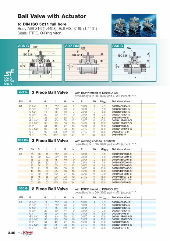
Ball Valve with Actuator
to DIN ISO 5211 full bore
Body AISI 316 (1.4408), Ball AISI 316L (1.4401)Seals: PTFE, O-Ring Viton
306 G
307 DN
360 G
dG
Hh
L
SW
ISO 5211
FSW
ISO 5211
F
D d
L
Hh
dG
Hh
L
SW
ISO 5211F
306 G 307 DN 360 G
PN G d L H h F SW MtNm Ball Valve sf-No.
63 G 1/4” 11 55** 40 7 03/04 9 4,5 306G14F0304-5iG 3/8” 12,5 60** 40 7 03/04 9 5,0 306G38F0304-5iG 1/2” 16 75 40 7 03/04 9 6,0 306G12F0304-5iG 3/4” 20 80 44 9 03/04 11 7,0 306G34F0304-5iG 1” 25 90 52 12 04/05 11 8,0 306G1F0405-5iG 1 1/4” 32 110 58 12 04/05 14 13,0 306G114F0405-5iG 1 1/2” 38 120 68 16 05/07 14 20,0 306G112F0507-5iG 2” 51 140 77 16 05/07 14 29,0 306G2F0507-5iG 2 1/2” 65 185 98 19 07/10 17 75,0 306G212F0710-5iG 3” 80 205 110 19 07/10 17 98,0 306G3F0710-5iG 4” 100 240 138 24 10 22 115,0 306G4F10-5i
3 Piece Ball Valve with BSPP thread to DIN/ISO 228overall length to DIN 3202 part 4-M3, (except: "**”)
306 G
PN DN D d L H h F SW MtNm Ball Valve sf-No.
63 08 20 11 55** 40 7 03/04 9 4,5 307DN08F0304-5i10 20 12,5 60** 40 7 03/04 9 5,0 307DN10F0304-5i15 23 16 75 40 9 03/04 9 6,0 307DN15F0304-5i20 28 20 90 44 9 03/04 11 7,0 307DN20F0304-5i25 34 20 100 52 12 04/05 11 8,0 307DN25F0405-5i32 41 32 110 58 12 04/05 14 13,0 307DN32F0405-5i40 49 38 125 68 16 05/07 14 20,0 307DN40F0507-5i50 62 51 150 77 16 05/07 14 29,0 307DN50F0507-5i65 78 65 190 98 19 07/10 17 75,0 307DN65F0710-5i80 94 80 220 110 19 07/10 17 98,0 307DN80F0710-5i
100 125 100 270 138 24 10 22 115,0 307DN100F10-5i
3 Piece Ball Valve with welding ends to DIN 3239overall length to DIN 3202 part 4-M3, (except: "**”)
307 DN
PN G d L H h F SW MtNm Ball Valve sf-No.
63 G 1/4” 11 55** 40 7 03/04 9 4,5 360G14F0304-5iG 3/8” 12,5 60** 40 7 03/04 9 5,0 360G38F0304-5iG 1/2” 16 75 40 7 03/04 9 6,0 360G12F0304-5iG 3/4” 20 80 44 9 03/04 9 7,0 360G34F0304-5iG 1” 25 90 52 12 04/05 11 8,0 360G1F0405-5iG 1 1/4” 32 110 58 12 04/05 11 13,0 360G114F0405-5iG 1 1/2” 38 120 68 16 05/07 14 20,0 360G112F0507-5iG 2” 51 140 77 16 05/07 14 29,0 360G2F0507-5iG 2 1/2” 65 185 98 19 07/10 17 75,0 360G212F0710-5iG 3” 80 205 110 19 07/10 17 98,0 360G3F0710-5i
2 Piece Ball Valve with BSPP thread to DIN/ISO 228overall length to DIN 3202 part 4-M3, (except: "**”)
360 G
3.41
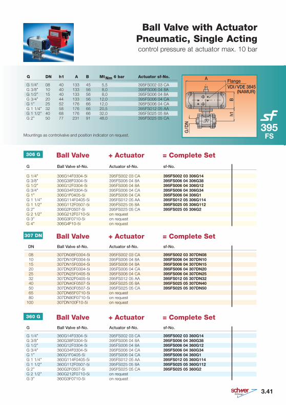
Ball Valve with Actuator
Pneumatic, Single Actingcontrol pressure at actuator max. 10 bar
395FS
G Ball Valve sf-No. Actuator sf-No. sf-No.
G 1/4” 306G14F0304-5i 395FS002 03 CA 395FS002 03 306G14
G 3/8” 306G38F0304-5i 395FS006 04 8A 395FS006 04 306G38
G 1/2” 306G12F0304-5i 395FS006 04 8A 395FS006 04 306G12
G 3/4” 306G34F0304-5i 395FS006 04 CA 395FS006 04 306G34
G 1” 306G1F0405-5i 395FS006 04 CA 395FS006 04 306G1
G 1 1/4” 306G114F0405-5i 395FS012 05 AA 395FS012 05 306G114
G 1 1/2” 306G112F0507-5i 395FS025 05 8A 395FS025 05 306G112
G 2” 306G2F0507-5i 395FS025 05 CA 395FS025 05 306G2
G 2 1/2” 306G212F0710-5i on requestG 3” 306G3F0710-5i on requestG 4” 306G4F10-5i on request
Ball Valve + Actuator = Complete Set306 G
DN Ball Valve sf-No. Actuator sf-No. sf-No.
08 307DN08F0304-5i 395FS002 03 CA 395FS002 03 307DN08
10 307DN10F0304-5i 395FS006 04 8A 395FS006 04 307DN10
15 307DN15F0304-5i 395FS006 04 8A 395FS006 04 307DN15
20 307DN20F0304-5i 395FS006 04 CA 395FS006 04 307DN20
25 307DN25F0405-5i 395FS006 04 CA 395FS006 04 307DN25
32 307DN32F0405-5i 395FS012 05 AA 395FS012 05 307DN32
40 307DN40F0507-5i 395FS025 05 8A 395FS025 05 307DN40
50 307DN50F0507-5i 395FS025 05 CA 395FS025 05 307DN50
65 307DN65F0710-5i on request80 307DN80F0710-5i on request
100 307DN100F10-5i on request
Ball Valve + Actuator = Complete Set307 DN
G Ball Valve sf-No. Actuator sf-No. sf-No.
G 1/4” 360G14F0304-5i 395FS002 03 CA 395FS002 03 360G14
G 3/8” 360G38F0304-5i 395FS006 04 8A 395FS006 04 360G38
G 1/2” 360G12F0304-5i 395FS006 04 8A 395FS006 04 360G12
G 3/4” 360G34F0304-5i 395FS006 04 CA 395FS006 04 360G34
G 1” 360G1F0405-5i 395FS006 04 CA 395FS006 04 360G1
G 1 1/4” 360G114F0405-5i 395FS012 05 AA 395FS012 05 360G114
G 1 1/2” 360G112F0507-5i 395FS025 05 8A 395FS025 05 360G112
G 2” 360G2F0507-5i 395FS025 05 CA 395FS025 05 360G2
G 2 1/2” 360G212F0710-5i on requestG 3” 360G3F0710-5i on request
360 G Ball Valve + Actuator = Complete Set
G DN h1 A B MtNm 6 bar Actuator sf-No.
G 1/4” 08 40 133 45 5,5 395FS002 03 CAG 3/8” 10 40 133 56 8,0 395FS006 04 8AG 1/2” 15 40 133 56 8,0 395FS006 04 8AG 3/4” 20 44 133 56 12,0 395FS006 04 CAG 1” 25 52 176 66 12,0 395FS006 04 CAG 1 1/4” 32 58 176 66 20,5 395FS012 05 AAG 1 1/2” 40 68 176 66 32,0 395FS025 05 8AG 2” 50 77 231 91 48,0 395FS025 05 CA
VDI /VDE 3845 (NAMUR)
FlangeA
Bh
1
G/D
N
Mountings as controlvalve and position indicator on request.

3.42
Ball Valve with Actuator
Pneumatic, Double Actingcontrol pressure at actuator max. 10 bar
395FD
G Ball Valve sf-No. Actuator sf-No. sf-No.
G 1/4” 306G14F0304-5i 395FD001 03 0A 395FD001 03 306G14
G 3/8” 306G38F0304-5i 395FD002 03 0A 395FD002 03 306G38
G 1/2” 306G12F0304-5i 395FD002 03 0A 395FD002 03 306G12
G 3/4” 306G34F0304-5i 395FD002 03 0A 395FD002 03 306G34
G 1” 306G1F0405-5i 395FD006 04 0A 395FD006 04 306G1
G 1 1/4” 306G114F0405-5i 395FD006 04 0A 395FD006 04 306G114
G 1 1/2” 306G112F0507-5i 395FD006 05 0A 395FD006 05 306G112
G 2” 306G2F0507-5i 395FD012 05 0A 395FD012 05 306G2
G 2 1/2” 306G212F0710-5i on requestG 3” 306G3F0710-5i on requestG 4” 306G4F10-5i on request
Ball Valve + Actuator = Complete Set306 G
DN Ball Valve sf-No. Actuator sf-No. sf-No.
08 307DN08F0304-5i 395FD001 03 0A 395FD001 03 307DN08
10 307DN10F0304-5i 395FD002 03 0A 395FD002 03 307DN10
15 307DN15F0304-5i 395FD002 03 0A 395FD002 03 307DN15
20 307DN20F0304-5i 395FD002 03 0A 395FD002 03 307DN20
25 307DN25F0405-5i 395FD006 04 0A 395FD006 04 307DN25
32 307DN32F0405-5i 395FD006 04 0A 395FD006 04 307DN32
40 307DN40F0507-5i 395FD006 05 0A 395FD006 05 307DN40
50 307DN50F0507-5i 395FD012 05 0A 395FD012 05 307DN50
65 307DN65F0710-5i on request80 307DN80F0710-5i on request
100 307DN100F10-5i on request
Ball Valve + Actuator = Complete Set307 DN
G Ball Valve sf-No. Actuator sf-No. sf-No.
G 1/4” 360G14F0304-5i 395FD001 03 0A 395FD001 03 360G14
G 3/8” 360G38F0304-5i 395FD002 03 0A 395FD002 03 360G38
G 1/2” 360G12F0304-5i 395FD002 03 0A 395FD002 03 360G12
G 3/4” 360G34F0304-5i 395FD002 03 0A 395FD002 03 360G34
G 1” 360G1F0405-5i 395FD006 04 0A 395FD006 04 360G1
G 1 1/4” 360G114F0405-5i 395FD006 04 0A 395FD00604 360G114
G 1 1/2” 360G112F0507-5i 395FD006 05 0A 395FD006 05 360G112
G 2” 360G2F0507-5i 395FD012 05 0A 395FD012 05 360G2
G 2 1/2” 360G212F0710-5i on requestG 3” 360G3F0710-5i on request
360 G Ball Valve + Actuator = Complete Set
G DN h1 A B MtNm 6 bar Actuator sf-No.
G 1/4” 08 40 133 45 7,5 395FD001 03 0AG 3/8” 10 40 133 56 16,0 395FD002 03 0AG 1/2” 15 40 133 56 16,0 395FD002 03 0AG 3/4” 20 44 133 56 16,0 395FD002 03 0AG 1” 25 52 176 66 37,0 395FD006 04 0AG 1 1/4” 32 58 176 66 37,0 395FD006 04 0AG 1 1/2” 40 68 176 66 37,0 395FD006 05 0AG 2” 50 77 231 91 74,0 395FD012 05 0A
Mountings as controlvalve and position indicator on request.
VDI /VDE 3845 (NAMUR)
FlangeA
Bh
1
G/D
N

3.43
Ball Valve with
Electric ActuatorVoltage optional 24V/C (=) or 220V/VC (~)
Protection class IP65, temperature –10°C to +50°C
G Ball Valve sf-No. Actuator sf-No. sf-No.
G 1/4” 306G14F0304-5i 399RO F03 SW9 24V= or 220V~ 399RO F03 ... V 306G14
G 3/8” 306G38F0304-5i 399RO F03 SW9 24V= or 220V~ 399RO F03 ... V 306G38
G 1/2” 306G12F0304-5i 399RO F03 SW9 24V= or 220V~ 399RO F03 ... V 306G12
G 3/4” 306G34F0304-5i 399RO F03 SW9 24V= or 220V~ 399RO F03 ... V 306G34
G 1” 306G1F0405-5i 399RO F05 SW11 24V= or 220V~ 399RO F05 ... V 306G1
G 1 1/4” 306G114F0405-5i 399RO F05 SW11 24V= or 220V~ 399RO F05 ... V 306G114
G 1 1/2” 306G112F0507-5i 399R1 F07 SW14 24V= or 220V~ 399R1 F07 ... V 306G112
G 2” 306G2F0507-5i 399R1 F07 SW14 24V= or 220V~ 399R1 F07 ... V 306G2
G 2 1/2” 306G212F0710-5i on request qG 3” 306G3F0710-5i on request please enter voltage G 4” 306G4F10-5i on request
Ball Valve + Actuator = Complete Set306 G
DN Ball Valve sf-No. Actuator sf-No. sf-No.
08 307DN08F0304-5i 399RO F03 SW9 24V= or 220V~ 399RO F03 ... V 307DN08
10 307DN10F0304-5i 399RO F03 SW9 24V= or 220V~ 399RO F03 ... V 307DN10
15 307DN15F0304-5i 399RO F03 SW9 24V= or 220V~ 399RO F03 ... V 307DN15
20 307DN20F0304-5i 399RO F03 SW9 24V= or 220V~ 399RO F03 ... V 307DN20
25 307DN25F0405-5i 399RO F05 SW11 24V= or 220V~ 399RO F05 ... V 307DN25
32 307DN32F0405-5i 399RO F05 SW11 24V= or 220V~ 399RO F05 ... V 307DN32
40 307DN40F0507-5i 399R1 F07 SW14 24V= or 220V~ 399R1 F07 ... V 307DN40
50 307DN50F0507-5i 399R1 F07 SW14 24V= or 220V~ 399R1 F07 ... V 307DN50
65 307DN65F0710-5i on request q80 307DN80F0710-5i on request please enter voltage
100 307DN100F10-5i on request
Ball Valve + Actuator = Complete Set307 DN
G Ball Valve sf-No. Actuator sf-No. sf-No.
G 1/4” 360G14F0304-5i 399RO F03 SW9 24V= or 220V~ 399RO F03 ... V 360G14
G 3/8” 360G38F0304-5i 399RO F03 SW9 24V= or 220V~ 399RO F03 ... V 360G38
G 1/2” 360G12F0304-5i 399RO F03 SW9 24V= or 220V~ 399RO F03 ... V 360G12
G 3/4” 360G34F0304-5i 399RO F03 SW9 24V= or 220V~ 399RO F03 ... V 360G34
G 1” 360G1F0405-5i 399RO F05 SW11 24V= or 220V~ 399RO F05 ... V 360G1
G 1 1/4” 360G114F0405-5i 399RO F05 SW11 24V= or 220V~ 399RO F05 ... V 360G114
G 1 1/2” 360G112F0507-5i 399R1 F07 SW14 24V= or 220V~ 399R1 F07 ... V 360G112
G 2” 360G2F0507-5i 399R1 F07 SW14 24V= or 220V~ 399R1 F07 ... V 360G2
G 2 1/2” 360G212F0710-5i on request qG 3” 360G3F0710-5i on request please enter voltage
360 G Ball Valve + Actuator = Complete Set
G DN h1 A B MtNm 6 bar Actuator sf-No.
G 1/4” 08 40 169 147 20,0 399RO F03 SW9G 3/8” 10 40 169 147 20,0 399RO F03 SW9G 1/2” 15 40 169 147 20,0 399RO F03 SW9G 3/4” 20 44 169 147 20,0 399RO F03 SW9G 1” 25 52 169 147 20,0 399RO F05 SW11G 1 1/4” 32 58 169 147 20,0 399RO F05 SW11G 1 1/2” 40 68 169 195 55,0 399R1 F07 SW14G 2” 50 77 169 195 55,0 399R1 F07 SW14
Manipulating time size RO: 24V/DC ca. 9,0 sec. 220V/VC ca. 7,5 sec.
size R1: 24V/DC ca. 25,0 sec. 220V/VC ca. 20,0 sec.
399RO
A
Bh
1
G/D
N