one of the primary goals of physics is to find simple ways of …rodshome.com/apphysics2/halliday...
TRANSCRIPT

CHAPTER
23
GAUSS' LAW
23-1 What is Physics?
One of the primary goals of physics is to find simple ways of solving seemingly complex problems. One of the main tools of
physics in attaining this goal is the use of symmetry. For example, in finding the electric field of the charged ring of Fig. 22-
10 and the charged rod of Fig. 22-11, we considered the fields of charge elements in the ring and rod. Then
we simplified the calculation of by using symmetry to discard the perpendicular components of the vectors. That saved
us some work.
For certain charge distributions involving symmetry, we can save far more work by using a law called Gauss' law, developed by
German mathematician and physicist Carl Friedrich Gauss (1777–1855). Instead of considering the fields of charge
elements in a given charge distribution, Gauss' law considers a hypothetical (imaginary) closed surface enclosing the charge
distribution. This Gaussian surface, as it is called, can have any shape, but the shape that minimizes our calculations of the
electric field is one that mimics the symmetry of the charge distribution. For example, if the charge is spread uniformly over a
sphere, we enclose the sphere with a spherical Gaussian surface, such as the one in Fig. 23-1, and then, as we discuss in this
chapter, find the electric field on the surface by using the fact that
Gauss' law relates the electric fields at points on a (closed) Gaussian surface to the net charge enclosed by that
surface.
We can also use Gauss' law in reverse: If we know the electric field on a Gaussian surface, we can find the net charge enclosed
by the surface. As a limited example, suppose that the electric field vectors in Fig. 23-1 all point radially outward from the
center of the sphere and have equal magnitude. Gauss' law immediately tells us that the spherical surface must enclose a net
positive charge that is either a particle or distributed spherically. However, to calculate how much charge is enclosed, we need a
way of calculating how much electric field is intercepted by the Gaussian surface in Fig. 23-1. This measure of intercepted field
is called flux, which we discuss next.
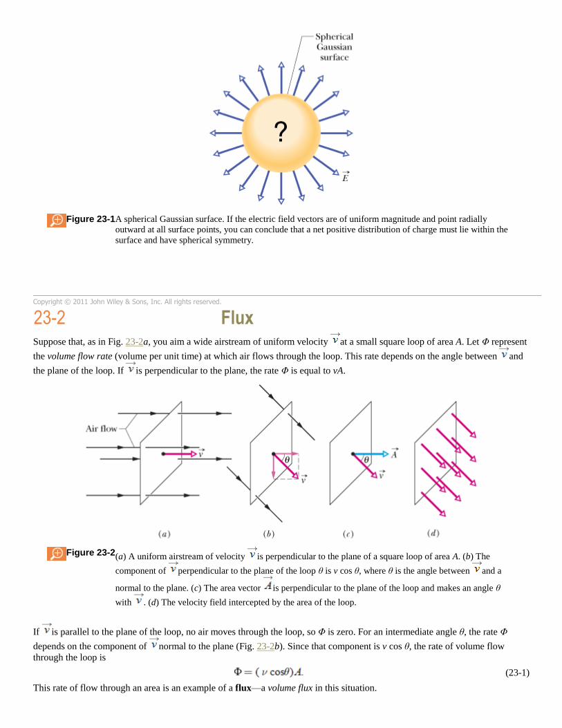
Figure 23-1 A spherical Gaussian surface. If the electric field vectors are of uniform magnitude and point radially
outward at all surface points, you can conclude that a net positive distribution of charge must lie within the
surface and have spherical symmetry.
Copyright © 2011 John Wiley & Sons, Inc. All rights reserved.
23-2 Flux
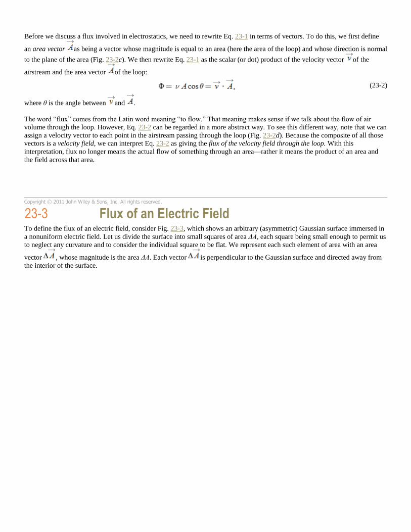
Suppose that, as in Fig. 23-2a, you aim a wide airstream of uniform velocity at a small square loop of area A. Let Φ represent
the volume flow rate (volume per unit time) at which air flows through the loop. This rate depends on the angle between and
the plane of the loop. If is perpendicular to the plane, the rate Φ is equal to vA.
Figure 23-2 (a) A uniform airstream of velocity is perpendicular to the plane of a square loop of area A. (b) The
component of perpendicular to the plane of the loop θ is v cos θ, where θ is the angle between and a
normal to the plane. (c) The area vector is perpendicular to the plane of the loop and makes an angle θ
with . (d) The velocity field intercepted by the area of the loop.
If is parallel to the plane of the loop, no air moves through the loop, so Φ is zero. For an intermediate angle θ, the rate Φ
depends on the component of normal to the plane (Fig. 23-2b). Since that component is v cos θ, the rate of volume flow
through the loop is
(23-1)
This rate of flow through an area is an example of a flux—a volume flux in this situation.
Before we discuss a flux involved in electrostatics, we need to rewrite Eq. 23-1 in terms of vectors. To do this, we first define
an area vector as being a vector whose magnitude is equal to an area (here the area of the loop) and whose direction is normal
to the plane of the area (Fig. 23-2c). We then rewrite Eq. 23-1 as the scalar (or dot) product of the velocity vector of the
airstream and the area vector of the loop:
(23-2)
where θ is the angle between and .
The word “flux” comes from the Latin word meaning “to flow.” That meaning makes sense if we talk about the flow of air
volume through the loop. However, Eq. 23-2 can be regarded in a more abstract way. To see this different way, note that we can
assign a velocity vector to each point in the airstream passing through the loop (Fig. 23-2d). Because the composite of all those
vectors is a velocity field, we can interpret Eq. 23-2 as giving the flux of the velocity field through the loop. With this
interpretation, flux no longer means the actual flow of something through an area—rather it means the product of an area and
the field across that area.
Copyright © 2011 John Wiley & Sons, Inc. All rights reserved.
23-3 Flux of an Electric Field
To define the flux of an electric field, consider Fig. 23-3, which shows an arbitrary (asymmetric) Gaussian surface immersed in
a nonuniform electric field. Let us divide the surface into small squares of area ΔA, each square being small enough to permit us
to neglect any curvature and to consider the individual square to be flat. We represent each such element of area with an area
vector , whose magnitude is the area ΔA. Each vector is perpendicular to the Gaussian surface and directed away from
the interior of the surface.
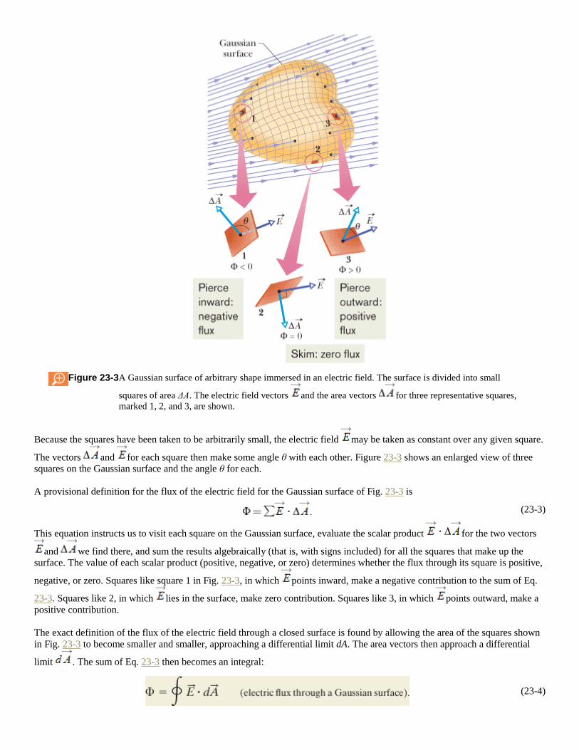
Figure 23-3 A Gaussian surface of arbitrary shape immersed in an electric field. The surface is divided into small
squares of area ΔA. The electric field vectors and the area vectors for three representative squares,
marked 1, 2, and 3, are shown.
Because the squares have been taken to be arbitrarily small, the electric field may be taken as constant over any given square.
The vectors and for each square then make some angle θ with each other. Figure 23-3 shows an enlarged view of three
squares on the Gaussian surface and the angle θ for each.
A provisional definition for the flux of the electric field for the Gaussian surface of Fig. 23-3 is
(23-3)
This equation instructs us to visit each square on the Gaussian surface, evaluate the scalar product for the two vectors
and we find there, and sum the results algebraically (that is, with signs included) for all the squares that make up the
surface. The value of each scalar product (positive, negative, or zero) determines whether the flux through its square is positive,
negative, or zero. Squares like square 1 in Fig. 23-3, in which points inward, make a negative contribution to the sum of Eq.
23-3. Squares like 2, in which lies in the surface, make zero contribution. Squares like 3, in which points outward, make a
positive contribution.
The exact definition of the flux of the electric field through a closed surface is found by allowing the area of the squares shown
in Fig. 23-3 to become smaller and smaller, approaching a differential limit dA. The area vectors then approach a differential
limit . The sum of Eq. 23-3 then becomes an integral:
(23-4)
The loop on the integral sign indicates that the integration is to be taken over the entire (closed) surface. The flux of the electric
field is a scalar, and its SI unit is the newton–square-meter per coulomb (N · m2/C).
We can interpret Eq. 23-4 in the following way: First recall that we can use the density of electric field lines passing through an
area as a proportional measure of the magnitude of the electric field there. Specifically, the magnitude E is proportional to the
number of electric field lines per unit area. Thus, the scalar product in Eq. 23-4 is proportional to the number of electric
field lines passing through area . Then, because the integration in Eq. 23-4 is carried out over a Gaussian surface, which is
closed, we see that
The electric flux Φ through a Gaussian surface is proportional to the net number of electric field lines passing
through that surface.
CHECKPOINT 1
The figure here shows a Gaussian cube of face area A immersed in a uniform electric field that has
the positive direction of the z axis. In terms of E and A, what is the flux through (a) the front face
(which is in the xy plane), (b) the rear face, (c) the top face, and (d) the whole cube?
Top of Form
Sample Problem
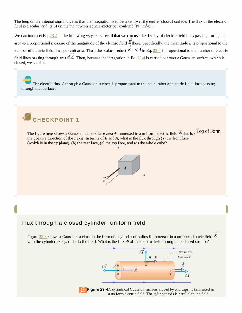
Flux through a closed cylinder, uniform field
Figure 23-4 shows a Gaussian surface in the form of a cylinder of radius R immersed in a uniform electric field ,
with the cylinder axis parallel to the field. What is the flux Φ of the electric field through this closed surface?
Figure 23-4 A cylindrical Gaussian surface, closed by end caps, is immersed in
a uniform electric field. The cylinder axis is parallel to the field
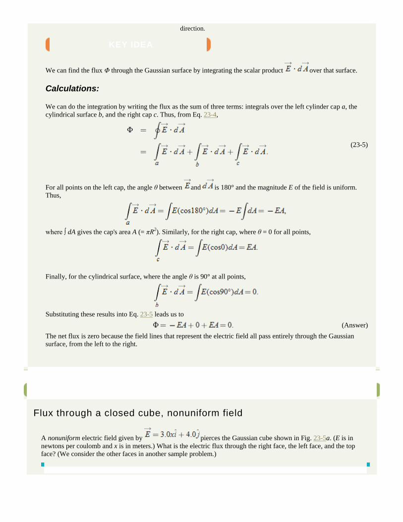
direction.
KEY IDEA
We can find the flux Φ through the Gaussian surface by integrating the scalar product over that surface.
Calculations:
We can do the integration by writing the flux as the sum of three terms: integrals over the left cylinder cap a, the
cylindrical surface b, and the right cap c. Thus, from Eq. 23-4,
(23-5)
For all points on the left cap, the angle θ between and is 180° and the magnitude E of the field is uniform.
Thus,
where ∫ dA gives the cap's area A (= πR2). Similarly, for the right cap, where θ = 0 for all points,
Finally, for the cylindrical surface, where the angle θ is 90° at all points,
Substituting these results into Eq. 23-5 leads us to
(Answer)
The net flux is zero because the field lines that represent the electric field all pass entirely through the Gaussian
surface, from the left to the right.
Sample Problem
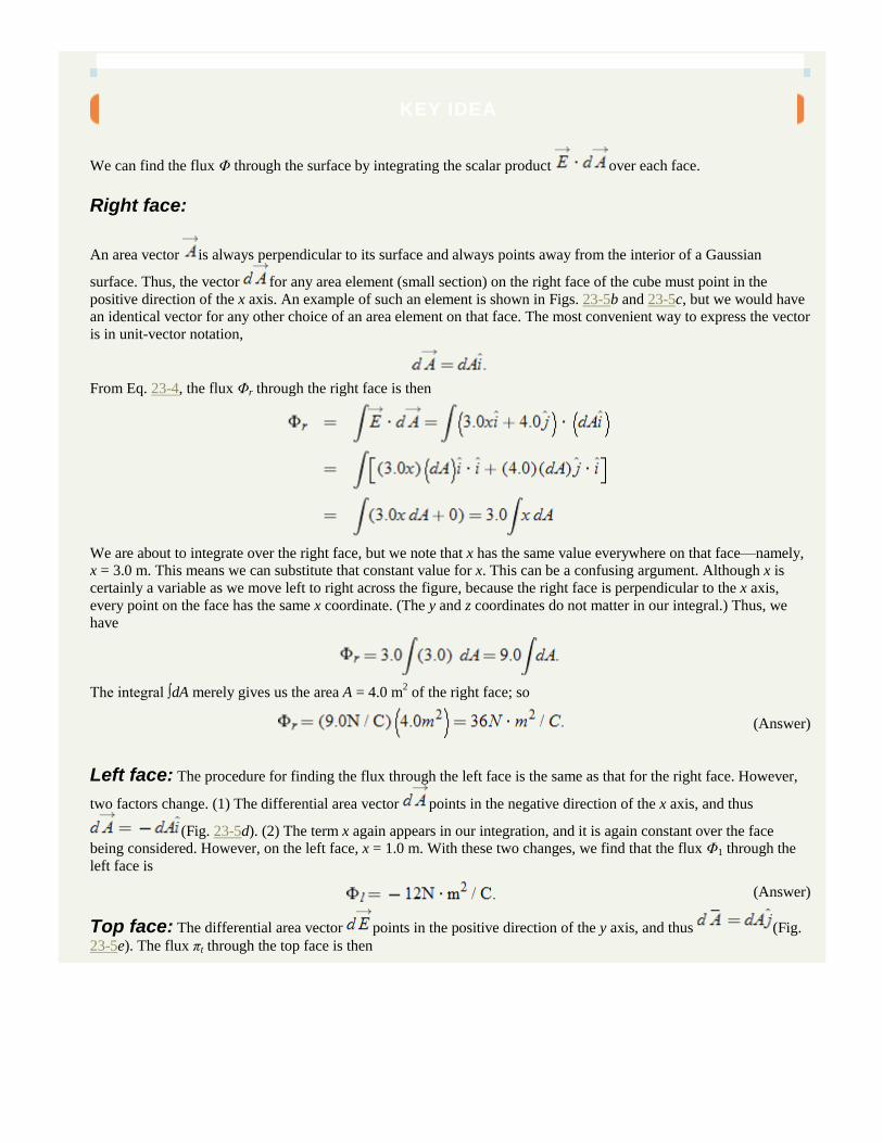
Flux through a closed cube, nonuniform field
A nonuniform electric field given by pierces the Gaussian cube shown in Fig. 23-5a. (E is in
newtons per coulomb and x is in meters.) What is the electric flux through the right face, the left face, and the top face? (We consider the other faces in another sample problem.)

Flux through a closed cube in a nonuniform field
Figure 23-5 (a) A Gaussian cube with one edge on the x axis lies within a nonuniform electric field that
depends on the value of x. (b) Each differential area element has an outward vector that is
perpendicular to the area. (c) Right face: the x component of the field pierces the area and
produces positive (outward) flux. The y component does not pierce the area and thus does
not produce any flux. (d) Left face: the x component of the field produces negative (inward)
flux. (e) Top face: the y component of the field produces positive (outward) flux.
KEY IDEA
We can find the flux Φ through the surface by integrating the scalar product over each face.
Right face:
An area vector is always perpendicular to its surface and always points away from the interior of a Gaussian
surface. Thus, the vector for any area element (small section) on the right face of the cube must point in the
positive direction of the x axis. An example of such an element is shown in Figs. 23-5b and 23-5c, but we would have
an identical vector for any other choice of an area element on that face. The most convenient way to express the vector
is in unit-vector notation,
From Eq. 23-4, the flux Φr through the right face is then
We are about to integrate over the right face, but we note that x has the same value everywhere on that face—namely,
x = 3.0 m. This means we can substitute that constant value for x. This can be a confusing argument. Although x is
certainly a variable as we move left to right across the figure, because the right face is perpendicular to the x axis,
every point on the face has the same x coordinate. (The y and z coordinates do not matter in our integral.) Thus, we
have
The integral ∫dA merely gives us the area A = 4.0 m2 of the right face; so
(Answer)
Left face: The procedure for finding the flux through the left face is the same as that for the right face. However,
two factors change. (1) The differential area vector points in the negative direction of the x axis, and thus
(Fig. 23-5d). (2) The term x again appears in our integration, and it is again constant over the face
being considered. However, on the left face, x = 1.0 m. With these two changes, we find that the flux Φ1 through the
left face is
(Answer)
Top face: The differential area vector points in the positive direction of the y axis, and thus (Fig.
23-5e). The flux πt through the top face is then
Copyright © 2011 John Wiley & Sons, Inc. All rights reserved.
23-4 Gauss' Law
Gauss' law relates the net flux Φ of an electric field through a closed surface (a Gaussian surface) to the net charge qenc that is
enclosed by that surface. It tells us that
(23-6)
By substituting Eq. 23-4, the definition of flux, we can also write Gauss' law as
(23-7)
Equations 23-6 and 23-7 hold only when the net charge is located in a vacuum or (what is the same for most practical purposes)
in air. In Chapter 25, we modify Gauss' law to include situations in which a material such as mica, oil, or glass is present.
In Eqs. 23-6 and 23-7, the net charge qenc is the algebraic sum of all the enclosed positive and negative charges, and it can be
positive, negative, or zero. We include the sign, rather than just use the magnitude of the enclosed charge, because the sign tells
us something about the net flux through the Gaussian surface: If qenc is positive, the net flux is outward; if qenc is negative, the
net flux is inward.
Charge outside the surface, no matter how large or how close it may be, is not included in the term qenc in Gauss' law. The exact
form and location of the charges inside the Gaussian surface are also of no concern; the only things that matter on the right side
of Eqs. 23-6 and 23-7 are the magnitude and sign of the net enclosed charge. The quantity on the left side of Eq. 23-7,
however, is the electric field resulting from all charges, both those inside and those outside the Gaussian surface. This statement
may seem to be inconsistent, but keep this in mind: The electric field due to a charge outside the Gaussian surface contributes
zero net flux through the surface, because as many field lines due to that charge enter the surface as leave it.
Let us apply these ideas to Fig. 23-6, which shows two point charges, equal in magnitude but opposite in sign, and the field
lines describing the electric fields the charges set up in the surrounding space. Four Gaussian surfaces are also shown, in cross
section. Let us consider each in turn.
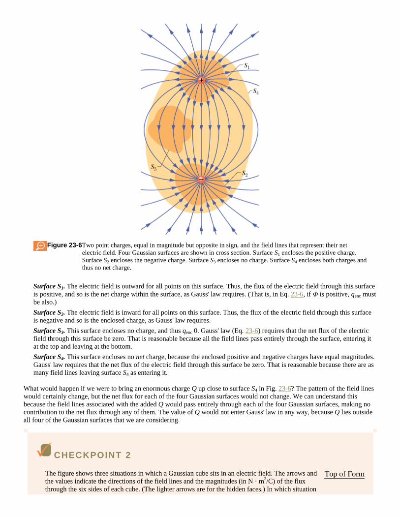
Figure 23-6 Two point charges, equal in magnitude but opposite in sign, and the field lines that represent their net
electric field. Four Gaussian surfaces are shown in cross section. Surface S1 encloses the positive charge.
Surface S2 encloses the negative charge. Surface S3 encloses no charge. Surface S4 encloses both charges and
thus no net charge.
Surface S1. The electric field is outward for all points on this surface. Thus, the flux of the electric field through this surface
is positive, and so is the net charge within the surface, as Gauss' law requires. (That is, in Eq. 23-6, if Φ is positive, qenc must
be also.)
Surface S2. The electric field is inward for all points on this surface. Thus, the flux of the electric field through this surface
is negative and so is the enclosed charge, as Gauss' law requires.
Surface S3. This surface encloses no charge, and thus qenc 0. Gauss' law (Eq. 23-6) requires that the net flux of the electric
field through this surface be zero. That is reasonable because all the field lines pass entirely through the surface, entering it
at the top and leaving at the bottom.
Surface S4. This surface encloses no net charge, because the enclosed positive and negative charges have equal magnitudes.
Gauss' law requires that the net flux of the electric field through this surface be zero. That is reasonable because there are as
many field lines leaving surface S4 as entering it.
What would happen if we were to bring an enormous charge Q up close to surface S4 in Fig. 23-6? The pattern of the field lines
would certainly change, but the net flux for each of the four Gaussian surfaces would not change. We can understand this
because the field lines associated with the added Q would pass entirely through each of the four Gaussian surfaces, making no
contribution to the net flux through any of them. The value of Q would not enter Gauss' law in any way, because Q lies outside
all four of the Gaussian surfaces that we are considering.
CHECKPOINT 2
The figure shows three situations in which a Gaussian cube sits in an electric field. The arrows and
the values indicate the directions of the field lines and the magnitudes (in N · m2/C) of the flux
through the six sides of each cube. (The lighter arrows are for the hidden faces.) In which situation
Top of Form
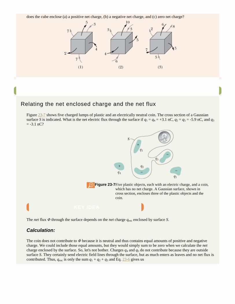
does the cube enclose (a) a positive net charge, (b) a negative net charge, and (c) zero net charge?
Sample Problem
Relating the net enclosed charge and the net flux
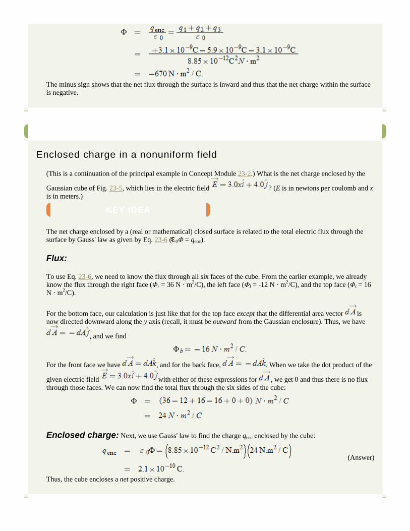
Figure 23-7 shows five charged lumps of plastic and an electrically neutral coin. The cross section of a Gaussian
surface S is indicated. What is the net electric flux through the surface if q1 = q4 = +3.1 nC, q2 = q5 = -5.9 nC, and q3
= -3.1 nC?
Figure 23-7 Five plastic objects, each with an electric charge, and a coin,
which has no net charge. A Gaussian surface, shown in
cross section, encloses three of the plastic objects and the
coin.
KEY IDEA
The net flux Φ through the surface depends on the net charge qenc enclosed by surface S.
Calculation:
The coin does not contribute to Φ because it is neutral and thus contains equal amounts of positive and negative
charge. We could include those equal amounts, but they would simply sum to be zero when we calculate the net
charge enclosed by the surface. So, let's not bother. Charges q4 and q5 do not contribute because they are outside
surface S. They certainly send electric field lines through the surface, but as much enters as leaves and no net flux is
contributed. Thus, qenc is only the sum q1 + q2 + q3 and Eq. 23-6 gives us
The minus sign shows that the net flux through the surface is inward and thus that the net charge within the surface
is negative.
Sample Problem
Enclosed charge in a nonuniform field
(This is a continuation of the principal example in Concept Module 23-2.) What is the net charge enclosed by the
Gaussian cube of Fig. 23-5, which lies in the electric field ? (E is in newtons per coulomb and x
is in meters.)
KEY IDEA
The net charge enclosed by a (real or mathematical) closed surface is related to the total electric flux through the
surface by Gauss' law as given by Eq. 23-6 ( 0Φ = qenc).
Flux:
To use Eq. 23-6, we need to know the flux through all six faces of the cube. From the earlier example, we already
know the flux through the right face (Φr = 36 N · m2/C), the left face (Φl = -12 N · m
2/C), and the top face (Φt = 16
N · m2/C).
For the bottom face, our calculation is just like that for the top face except that the differential area vector is
now directed downward along the y axis (recall, it must be outward from the Gaussian enclosure). Thus, we have
, and we find
For the front face we have , and for the back face, . When we take the dot product of the
given electric field with either of these expressions for , we get 0 and thus there is no flux
through those faces. We can now find the total flux through the six sides of the cube:
Enclosed charge: Next, we use Gauss' law to find the charge qenc enclosed by the cube:
(Answer)
Thus, the cube encloses a net positive charge.

Copyright © 2011 John Wiley & Sons, Inc. All rights reserved.
23-5 Gauss' Law and Coulomb's Law
Because Gauss' law and Coulomb's law are different ways of describing the relation between electric charge and electric field in
static situations, we should be able to derive each from the other. Here we derive Coulomb's law from Gauss' law and some
symmetry considerations.
Figure 23-8 shows a positive point charge q, around which we have drawn a concentric spherical Gaussian surface of radius r.
Let us divide this surface into differential areas dA. By definition, the area vector at any point is perpendicular to the surface
and directed outward from the interior. From the symmetry of the situation, we know that at any point the electric field is also
perpendicular to the surface and directed outward from the interior. Thus, since the angle θ between and is zero, we can
rewrite Eq. 23-7 for Gauss' law as
(23-8)
Here qenc = q. Although E varies radially with distance from q, it has the same value everywhere on the spherical surface. Since
the integral in Eq. 23-8 is taken over that surface, E is a constant in the integration and can be brought out in front of the integral
sign. That gives us
(23-9)
The integral is now merely the sum of all the differential areas dA on the sphere and thus is just the surface area, 4πr2.
Substituting this, we have
or
(23-10)
This is exactly Eq. 22-3, which we found using Coulomb's law.
Figure 23-8 A spherical Gaussian surface centered on a point charge q.
CHECKPOINT 3
Top of Form
There is a certain net flux Φi through a Gaussian sphere of radius r enclosing an isolated charged
particle. Suppose the enclosing Gaussian surface is changed to (a) a larger Gaussian sphere, (b) a Gaussian cube
with edge length equal to r, and (c) a Gaussian cube with edge length equal to 2r. In each case, is the net flux
through the new Gaussian surface greater than, less than, or equal to Φi?
Copyright © 2011 John Wiley & Sons, Inc. All rights reserved.
23-6 A Charged Isolated Conductor
Gauss' law permits us to prove an important theorem about conductors:
If an excess charge is placed on an isolated conductor, that amount of charge will move entirely to the surface of
the conductor. None of the excess charge will be found within the body of the conductor.
This might seem reasonable, considering that charges with the same sign repel one another. You might imagine that, by moving
to the surface, the added charges are getting as far away from one another as they can. We turn to Gauss' law for verification of
this speculation.
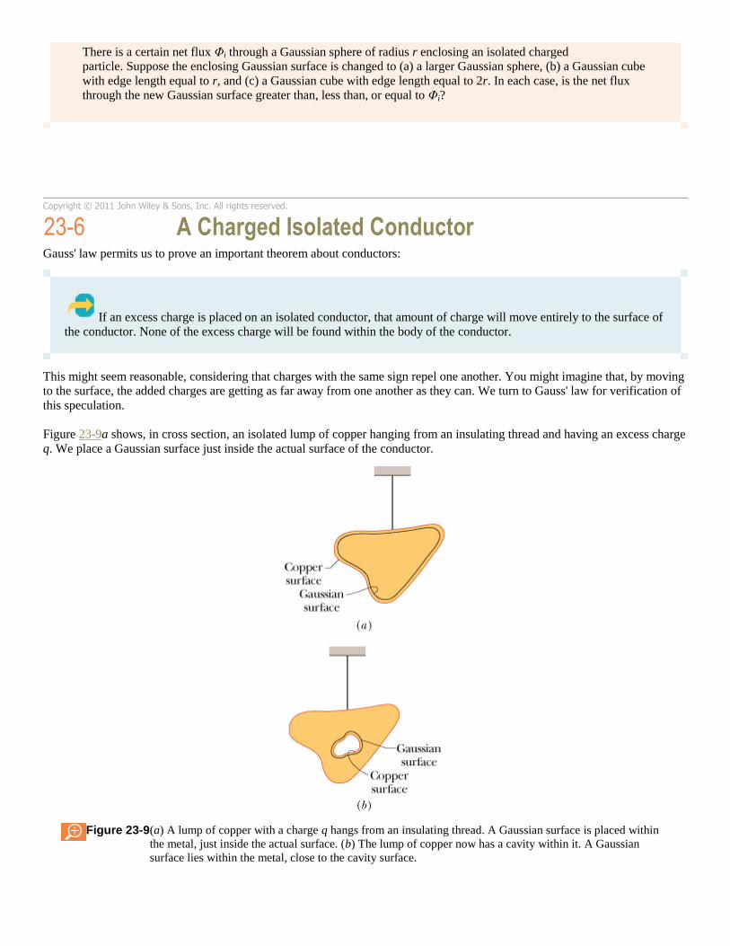
Figure 23-9a shows, in cross section, an isolated lump of copper hanging from an insulating thread and having an excess charge
q. We place a Gaussian surface just inside the actual surface of the conductor.
Figure 23-9 (a) A lump of copper with a charge q hangs from an insulating thread. A Gaussian surface is placed within
the metal, just inside the actual surface. (b) The lump of copper now has a cavity within it. A Gaussian
surface lies within the metal, close to the cavity surface.
The electric field inside this conductor must be zero. If this were not so, the field would exert forces on the conduction (free)
electrons, which are always present in a conductor, and thus current would always exist within a conductor. (That is, charge
would flow from place to place within the conductor.) Of course, there is no such perpetual current in an isolated conductor, and
so the internal electric field is zero.
(An internal electric field does appear as a conductor is being charged. However, the added charge quickly distributes itself in
such a way that the net internal electric field—the vector sum of the electric fields due to all the charges, both inside and
outside—is zero. The movement of charge then ceases, because the net force on each charge is zero; the charges are then in
electrostatic equilibrium.)
If is zero everywhere inside our copper conductor, it must be zero for all points on the Gaussian surface because that surface,
though close to the surface of the conductor, is definitely inside the conductor. This means that the flux through the Gaussian
surface must be zero. Gauss' law then tells us that the net charge inside the Gaussian surface must also be zero. Then because
the excess charge is not inside the Gaussian surface, it must be outside that surface, which means it must lie on the actual
surface of the conductor.
An Isolated Conductor with a Cavity
Figure 23-9b shows the same hanging conductor, but now with a cavity that is totally within the conductor. It is perhaps
reasonable to suppose that when we scoop out the electrically neutral material to form the cavity, we do not change the
distribution of charge or the pattern of the electric field that exists in Fig. 23-9a. Again, we must turn to Gauss' law for a
quantitative proof.
We draw a Gaussian surface surrounding the cavity, close to its surface but inside the conducting body. Because inside
the conductor, there can be no flux through this new Gaussian surface. Therefore, from Gauss' law, that surface can enclose no
net charge. We conclude that there is no net charge on the cavity walls; all the excess charge remains on the outer surface of the
conductor, as in Fig. 23-9a.
The Conductor Removed
Suppose that, by some magic, the excess charges could be “frozen” into position on the conductor's surface, perhaps by
embedding them in a thin plastic coating, and suppose that then the conductor could be removed completely. This is equivalent
to enlarging the cavity of Fig. 23-9b until it consumes the entire conductor, leaving only the charges. The electric field would
not change at all; it would remain zero inside the thin shell of charge and would remain unchanged for all external points. This
shows us that the electric field is set up by the charges and not by the conductor. The conductor simply provides an initial
pathway for the charges to take up their positions.
The External Electric Field
You have seen that the excess charge on an isolated conductor moves entirely to the conductor's surface. However, unless the
conductor is spherical, the charge does not distribute itself uniformly. Put another way, the surface charge density σ (charge per
unit area) varies over the surface of any nonspherical conductor. Generally, this variation makes the determination of the
electric field set up by the surface charges very difficult.
However, the electric field just outside the surface of a conductor is easy to determine using Gauss' law. To do this, we consider
a section of the surface that is small enough to permit us to neglect any curvature and thus to take the section to be flat. We then
imagine a tiny cylindrical Gaussian surface to be embedded in the section as in Fig. 23-10: One end cap is fully inside the conductor, the other is fully outside, and the cylinder is perpendicular to the conductor's surface.

Figure 23-10 (a) Perspective view and (b) side view of a tiny portion of a large, isolated conductor with excess positive
charge on its surface. A (closed) cylindrical Gaussian surface, embedded perpendicularly in the conductor,
encloses some of the charge. Electric field lines pierce the external end cap of the cylinder, but not the
internal end cap. The external end cap has area A and area vector .
The electric field at and just outside the conductor's surface must also be perpendicular to that surface. If it were not, then it
would have a component along the conductor's surface that would exert forces on the surface charges, causing them to move.
However, such motion would violate our implicit assumption that we are dealing with electrostatic equilibrium. Therefore, is
perpendicular to the conductor's surface.
We now sum the flux through the Gaussian surface. There is no flux through the internal end cap, because the electric field
within the conductor is zero. There is no flux through the curved surface of the cylinder, because internally (in the conductor)
there is no electric field and externally the electric field is parallel to the curved portion of the Gaussian surface. The only flux
through the Gaussian surface is that through the external end cap, where is perpendicular to the plane of the cap. We assume
that the cap area A is small enough that the field magnitude E is constant over the cap. Then the flux through the cap is EA, and
that is the net flux Φ through the Gaussian surface.
The charge qenc enclosed by the Gaussian surface lies on the conductor's surface in an area A. If σ is the charge per unit area,
then qenc is equal to σA. When we substitute σA for qenc and EA for Φ, Gauss' law (Eq. 23-6) becomes
from which we find
(23-11)
Thus, the magnitude of the electric field just outside a conductor is proportional to the surface charge density on the conductor.
If the charge on the conductor is positive, the electric field is directed away from the conductor as in Fig. 23-10. It is directed
toward the conductor if the charge is negative.
The field lines in Fig. 23-10 must terminate on negative charges somewhere in the environment. If we bring those charges near
the conductor, the charge density at any given location on the conductor's surface changes, and so does the magnitude of the
electric field. However, the relation between σ and E is still given by Eq. 23-11.

Sample Problem
Spherical metal shell, electric field and enclosed charge
Figure 23-11a shows a cross section of a spherical metal shell of inner radius R. A point charge of -5.0 μC is located
at a distance R/2 from the center of the shell. If the shell is electrically neutral, what are the (induced) charges on its
inner and outer surfaces? Are those charges uniformly distributed? What is the field pattern inside and outside the
shell?
Figure 23-11 (a) A negative point charge is located within a spherical metal shell that
is electrically neutral. (b) As a result, positive charge is nonuniformly
distributed on the inner wall of the shell, and an equal amount of
negative charge is uniformly distributed on the outer wall.
KEY IDEAS
Figure 23-11b shows a cross section of a spherical Gaussian surface within the metal, just outside the inner wall of
the shell. The electric field must be zero inside the metal (and thus on the Gaussian surface inside the metal). This
means that the electric flux through the Gaussian surface must also be zero. Gauss' law then tells us that the net
charge enclosed by the Gaussian surface must be zero.
Reasoning:
With a point charge of -5.0 μC within the shell, a charge of +5.0 μC must lie on the inner wall of the shell in order
that the net enclosed charge be zero. If the point charge were centered, this positive charge would be uniformly
distributed along the inner wall. However, since the point charge is off-center, the distribution of positive charge is
skewed, as suggested by Fig. 23-11b, because the positive charge tends to collect on the section of the inner wall
nearest the (negative) point charge.
Because the shell is electrically neutral, its inner wall can have a charge of +5.0 μC only if electrons, with a total
charge of -5.0 μC, leave the inner wall and move to the outer wall. There they spread out uniformly, as is also
suggested by Fig. 23-11b. This distribution of negative charge is uniform because the shell is spherical and because
the skewed distribution of positive charge on the inner wall cannot produce an electric field in the shell to affect the
distribution of charge on the outer wall. Furthermore, these negative charges repel one another.
The field lines inside and outside the shell are shown approximately in Fig. 23-11b. All the field lines intersect the shell and the point charge perpendicularly. Inside the shell the pattern of field lines is skewed because of the skew
of the positive charge distribution. Outside the shell the pattern is the same as if the point charge were centered and
the shell were missing. In fact, this would be true no matter where inside the shell the point charge happened to be
located.
Copyright © 2011 John Wiley & Sons, Inc. All rights reserved.
23-7 Applying Gauss' Law: Cylindrical Symmetry
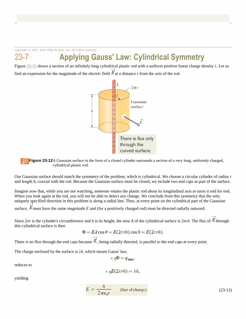
Figure 23-12 shows a section of an infinitely long cylindrical plastic rod with a uniform positive linear charge density λ. Let us
find an expression for the magnitude of the electric field at a distance r from the axis of the rod.
Figure 23-12 A Gaussian surface in the form of a closed cylinder surrounds a section of a very long, uniformly charged,
cylindrical plastic rod.
Our Gaussian surface should match the symmetry of the problem, which is cylindrical. We choose a circular cylinder of radius r
and length h, coaxial with the rod. Because the Gaussian surface must be closed, we include two end caps as part of the surface.
Imagine now that, while you are not watching, someone rotates the plastic rod about its longitudinal axis or turns it end for end.
When you look again at the rod, you will not be able to detect any change. We conclude from this symmetry that the only
uniquely specified direction in this problem is along a radial line. Thus, at every point on the cylindrical part of the Gaussian
surface, must have the same magnitude E and (for a positively charged rod) must be directed radially outward.
Since 2πr is the cylinder's circumference and h is its height, the area A of the cylindrical surface is 2πrh. The flux of through
this cylindrical surface is then
There is no flux through the end caps because , being radially directed, is parallel to the end caps at every point.
The charge enclosed by the surface is λh, which means Gauss' law,
reduces to
yielding
(23-12)
This is the electric field due to an infinitely long, straight line of charge, at a point that is a radial distance r from the line. The
direction of is radially outward from the line of charge if the charge is positive, and radially inward if it is negative. Equation
23-12 also approximates the field of a finite line of charge at points that are not too near the ends (compared with the distance
from the line).
Sample Problem
Gauss' law and an upward streamer in a lightning storm
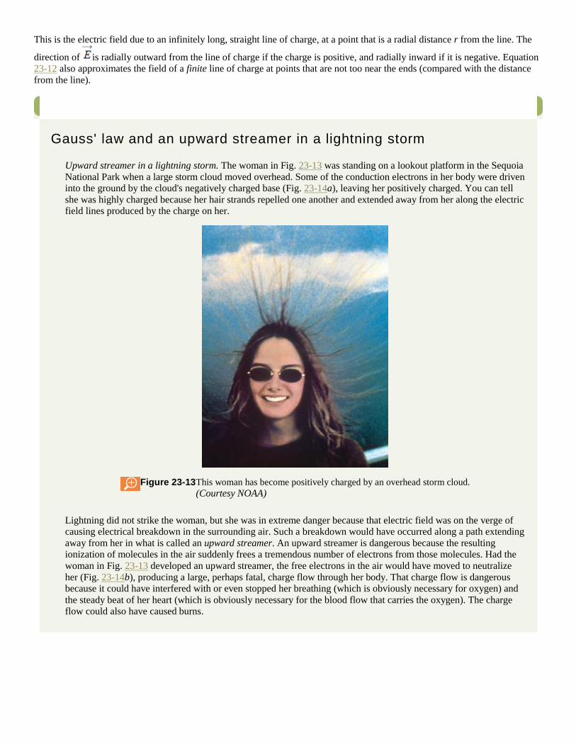
Upward streamer in a lightning storm. The woman in Fig. 23-13 was standing on a lookout platform in the Sequoia
National Park when a large storm cloud moved overhead. Some of the conduction electrons in her body were driven
into the ground by the cloud's negatively charged base (Fig. 23-14a), leaving her positively charged. You can tell
she was highly charged because her hair strands repelled one another and extended away from her along the electric
field lines produced by the charge on her.
Figure 23-13 This woman has become positively charged by an overhead storm cloud.
(Courtesy NOAA)
Lightning did not strike the woman, but she was in extreme danger because that electric field was on the verge of
causing electrical breakdown in the surrounding air. Such a breakdown would have occurred along a path extending
away from her in what is called an upward streamer. An upward streamer is dangerous because the resulting
ionization of molecules in the air suddenly frees a tremendous number of electrons from those molecules. Had the
woman in Fig. 23-13 developed an upward streamer, the free electrons in the air would have moved to neutralize
her (Fig. 23-14b), producing a large, perhaps fatal, charge flow through her body. That charge flow is dangerous
because it could have interfered with or even stopped her breathing (which is obviously necessary for oxygen) and
the steady beat of her heart (which is obviously necessary for the blood flow that carries the oxygen). The charge
flow could also have caused burns.
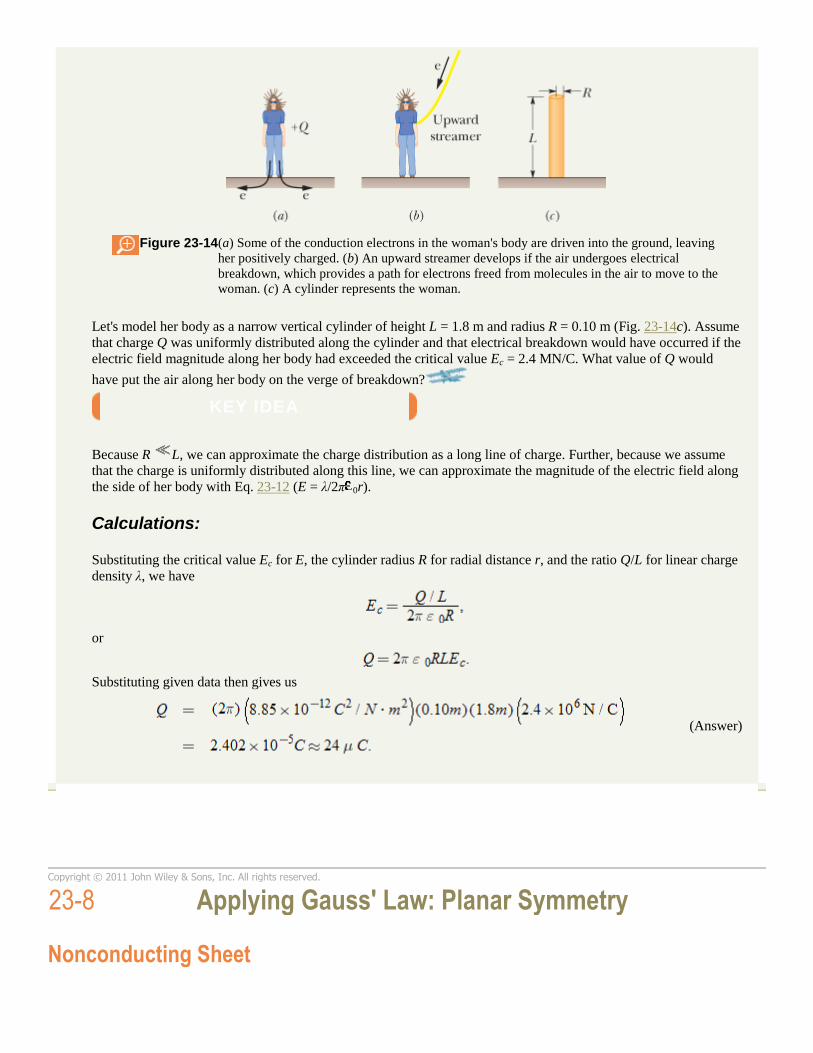
Figure 23-14 (a) Some of the conduction electrons in the woman's body are driven into the ground, leaving
her positively charged. (b) An upward streamer develops if the air undergoes electrical
breakdown, which provides a path for electrons freed from molecules in the air to move to the
woman. (c) A cylinder represents the woman.
Let's model her body as a narrow vertical cylinder of height L = 1.8 m and radius R = 0.10 m (Fig. 23-14c). Assume
that charge Q was uniformly distributed along the cylinder and that electrical breakdown would have occurred if the
electric field magnitude along her body had exceeded the critical value Ec = 2.4 MN/C. What value of Q would
have put the air along her body on the verge of breakdown?
KEY IDEA
Because R L, we can approximate the charge distribution as a long line of charge. Further, because we assume
that the charge is uniformly distributed along this line, we can approximate the magnitude of the electric field along
the side of her body with Eq. 23-12 (E = λ/2π 0r).
Calculations:
Substituting the critical value Ec for E, the cylinder radius R for radial distance r, and the ratio Q/L for linear charge
density λ, we have
or
Substituting given data then gives us
(Answer)
Copyright © 2011 John Wiley & Sons, Inc. All rights reserved.
23-8 Applying Gauss' Law: Planar Symmetry
Nonconducting Sheet

Figure 23-15 shows a portion of a thin, infinite, nonconducting sheet with a uniform (positive) surface charge density σ. A sheet
of thin plastic wrap, uniformly charged on one side, can serve as a simple model. Let us find the electric field a distance r in
front of the sheet.
Figure 23-15 (a) Perspective view and (b) side view of a portion of a very large, thin plastic sheet, uniformly charged on
one side to surface charge density σ. A closed cylindrical Gaussian surface passes through the sheet and is
perpendicular to it.
A useful Gaussian surface is a closed cylinder with end caps of area A, arranged to pierce the sheet perpendicularly as shown.
From symmetry, must be perpendicular to the sheet and hence to the end caps. Furthermore, since the charge is positive, is
directed away from the sheet, and thus the electric field lines pierce the two Gaussian end caps in an outward direction. Because
the field lines do not pierce the curved surface, there is no flux through this portion of the Gaussian surface. Thus is
simply E dA; then Gauss' law,
becomes
where σA is the charge enclosed by the Gaussian surface. This gives
(23-13)
Since we are considering an infinite sheet with uniform charge density, this result holds for any point at a finite distance from
the sheet. Equation 23-13 agrees with Eq. 22-27, which we found by integration of electric field components.
Two Conducting Plates
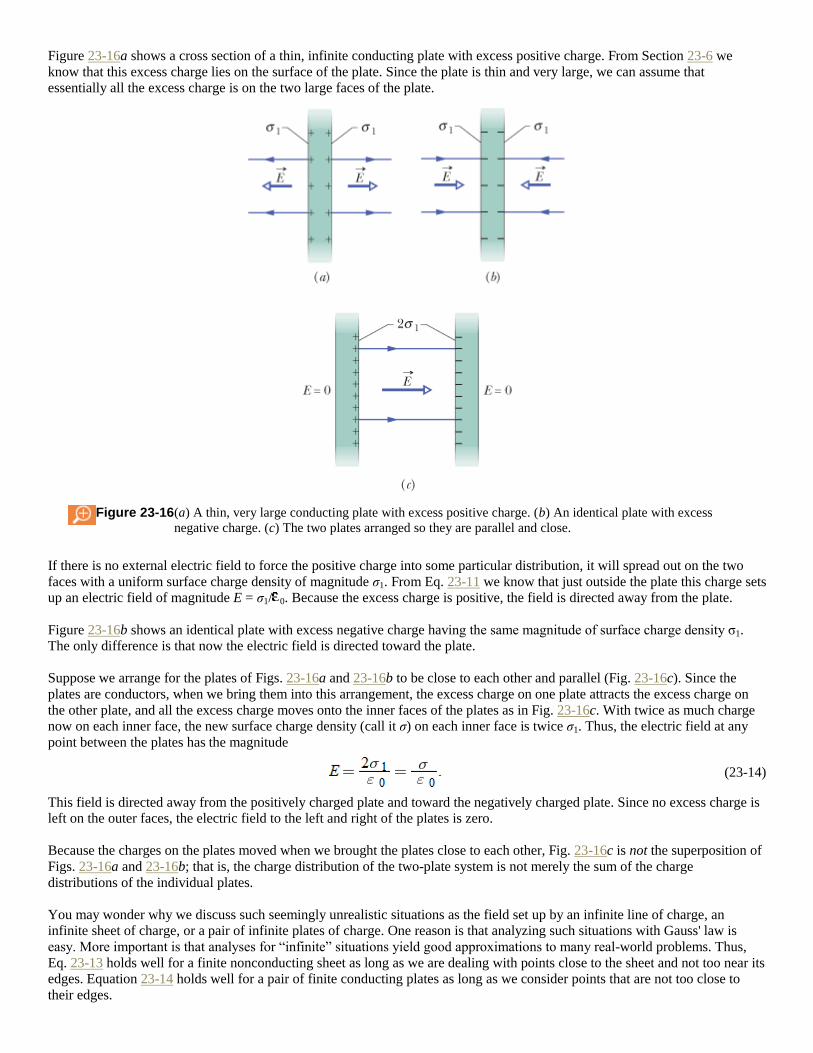
Figure 23-16a shows a cross section of a thin, infinite conducting plate with excess positive charge. From Section 23-6 we
know that this excess charge lies on the surface of the plate. Since the plate is thin and very large, we can assume that
essentially all the excess charge is on the two large faces of the plate.
Figure 23-16 (a) A thin, very large conducting plate with excess positive charge. (b) An identical plate with excess
negative charge. (c) The two plates arranged so they are parallel and close.
If there is no external electric field to force the positive charge into some particular distribution, it will spread out on the two
faces with a uniform surface charge density of magnitude σ1. From Eq. 23-11 we know that just outside the plate this charge sets
up an electric field of magnitude E = σ1/ 0. Because the excess charge is positive, the field is directed away from the plate.
Figure 23-16b shows an identical plate with excess negative charge having the same magnitude of surface charge density σ1.
The only difference is that now the electric field is directed toward the plate.
Suppose we arrange for the plates of Figs. 23-16a and 23-16b to be close to each other and parallel (Fig. 23-16c). Since the
plates are conductors, when we bring them into this arrangement, the excess charge on one plate attracts the excess charge on
the other plate, and all the excess charge moves onto the inner faces of the plates as in Fig. 23-16c. With twice as much charge
now on each inner face, the new surface charge density (call it σ) on each inner face is twice σ1. Thus, the electric field at any
point between the plates has the magnitude
(23-14)
This field is directed away from the positively charged plate and toward the negatively charged plate. Since no excess charge is
left on the outer faces, the electric field to the left and right of the plates is zero.
Because the charges on the plates moved when we brought the plates close to each other, Fig. 23-16c is not the superposition of
Figs. 23-16a and 23-16b; that is, the charge distribution of the two-plate system is not merely the sum of the charge
distributions of the individual plates.
You may wonder why we discuss such seemingly unrealistic situations as the field set up by an infinite line of charge, an infinite sheet of charge, or a pair of infinite plates of charge. One reason is that analyzing such situations with Gauss' law is
easy. More important is that analyses for “infinite” situations yield good approximations to many real-world problems. Thus,
Eq. 23-13 holds well for a finite nonconducting sheet as long as we are dealing with points close to the sheet and not too near its
edges. Equation 23-14 holds well for a pair of finite conducting plates as long as we consider points that are not too close to
their edges.
The trouble with the edges of a sheet or a plate, and the reason we take care not to deal with them, is that near an edge we can
no longer use planar symmetry to find expressions for the fields. In fact, the field lines there are curved (said to be an edge effect
or fringing), and the fields can be very difficult to express algebraically.
Sample Problem
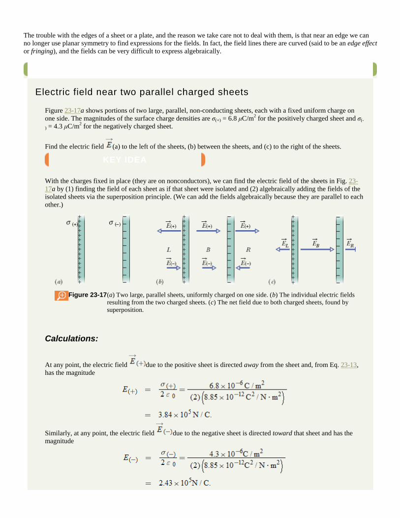
Electric field near two parallel charged sheets
Figure 23-17a shows portions of two large, parallel, non-conducting sheets, each with a fixed uniform charge on
one side. The magnitudes of the surface charge densities are σ(+) = 6.8 μC/m2 for the positively charged sheet and σ(-
) = 4.3 μC/m2 for the negatively charged sheet.
Find the electric field (a) to the left of the sheets, (b) between the sheets, and (c) to the right of the sheets.
KEY IDEA
With the charges fixed in place (they are on nonconductors), we can find the electric field of the sheets in Fig. 23-
17a by (1) finding the field of each sheet as if that sheet were isolated and (2) algebraically adding the fields of the
isolated sheets via the superposition principle. (We can add the fields algebraically because they are parallel to each
other.)
Figure 23-17 (a) Two large, parallel sheets, uniformly charged on one side. (b) The individual electric fields
resulting from the two charged sheets. (c) The net field due to both charged sheets, found by
superposition.
Calculations:
At any point, the electric field due to the positive sheet is directed away from the sheet and, from Eq. 23-13,
has the magnitude
Similarly, at any point, the electric field due to the negative sheet is directed toward that sheet and has the
magnitude

Figure 23-17b shows the fields set up by the sheets to the left of the sheets (L), between them (B), and to their right
(R).
The resultant fields in these three regions follow from the superposition principle. To the left, the field magnitude is
(Answer)
Because E(+) is larger than , the net electric field in this region is directed to the left, as Fig. 23-17c shows.
To the right of the sheets, the electric field has the same magnitude but is directed to the right, as Fig. 23-17c shows.
Between the sheets, the two fields add and we have
(Answer)
The electric field is directed to the right.
Copyright © 2011 John Wiley & Sons, Inc. All rights reserved.
23-9 Applying Gauss' Law: Spherical Symmetry
Here we use Gauss' law to prove the two shell theorems presented without proof in Section 21-4:
A shell of uniform charge attracts or repels a charged particle that is outside the shell as if all the shell's charge
were concentrated at the center of the shell.
If a charged particle is located inside a shell of uniform charge, there is no electrostatic force on the particle from
the shell.
Figure 23-18 shows a charged spherical shell of total charge q and radius R and two concentric spherical Gaussian surfaces, S1
and S2. If we followed the procedure of Section 23-5 as we applied Gauss' law to surface S2, for which r ≥ R, we would find that
(23-15)
This field is the same as one set up by a point charge q at the center of the shell of charge. Thus, the force produced by a shell of
charge q on a charged particle placed outside the shell is the same as the force produced by a point charge q located at the center
of the shell. This proves the first shell theorem.

Figure 23-18 A thin, uniformly charged, spherical shell with total charge q, in cross section. Two Gaussian surfaces S1
and S2 are also shown in cross section. Surface S2 encloses the shell, and S1 encloses only the empty
interior of the shell.
Applying Gauss' law to surface S1, for which r < R, leads directly to
(23-16)
because this Gaussian surface encloses no charge. Thus, if a charged particle were enclosed by the shell, the shell would exert
no net electrostatic force on the particle. This proves the second shell theorem.
Any spherically symmetric charge distribution, such as that of Fig. 23-19, can be constructed with a nest of concentric spherical
shells. For purposes of applying the two shell theorems, the volume charge density ρ should have a single value for each shell
but need not be the same from shell to shell. Thus, for the charge distribution as a whole, ρ can vary, but only with r, the radial
distance from the center. We can then examine the effect of the charge distribution “shell by shell.”
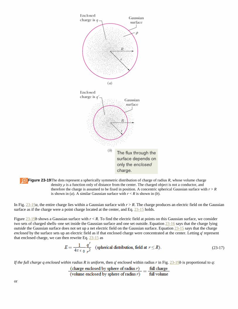
Figure 23-19 The dots represent a spherically symmetric distribution of charge of radius R, whose volume charge
density ρ is a function only of distance from the center. The charged object is not a conductor, and
therefore the charge is assumed to be fixed in position. A concentric spherical Gaussian surface with r > R
is shown in (a). A similar Gaussian surface with r < R is shown in (b).
In Fig. 23-19a, the entire charge lies within a Gaussian surface with r > R. The charge produces an electric field on the Gaussian
surface as if the charge were a point charge located at the center, and Eq. 23-15 holds.
Figure 23-19b shows a Gaussian surface with r < R. To find the electric field at points on this Gaussian surface, we consider
two sets of charged shells–one set inside the Gaussian surface and one set outside. Equation 23-16 says that the charge lying
outside the Gaussian surface does not set up a net electric field on the Gaussian surface. Equation 23-15 says that the charge
enclosed by the surface sets up an electric field as if that enclosed charge were concentrated at the center. Letting q' represent
that enclosed charge, we can then rewrite Eq. 23-15 as
(23-17)
If the full charge q enclosed within radius R is uniform, then q' enclosed within radius r in Fig. 23-19b is proportional to q:
or
(23-18)
This gives us
(23-19)
Substituting this into Eq. 23-17 yields
(23-
20)
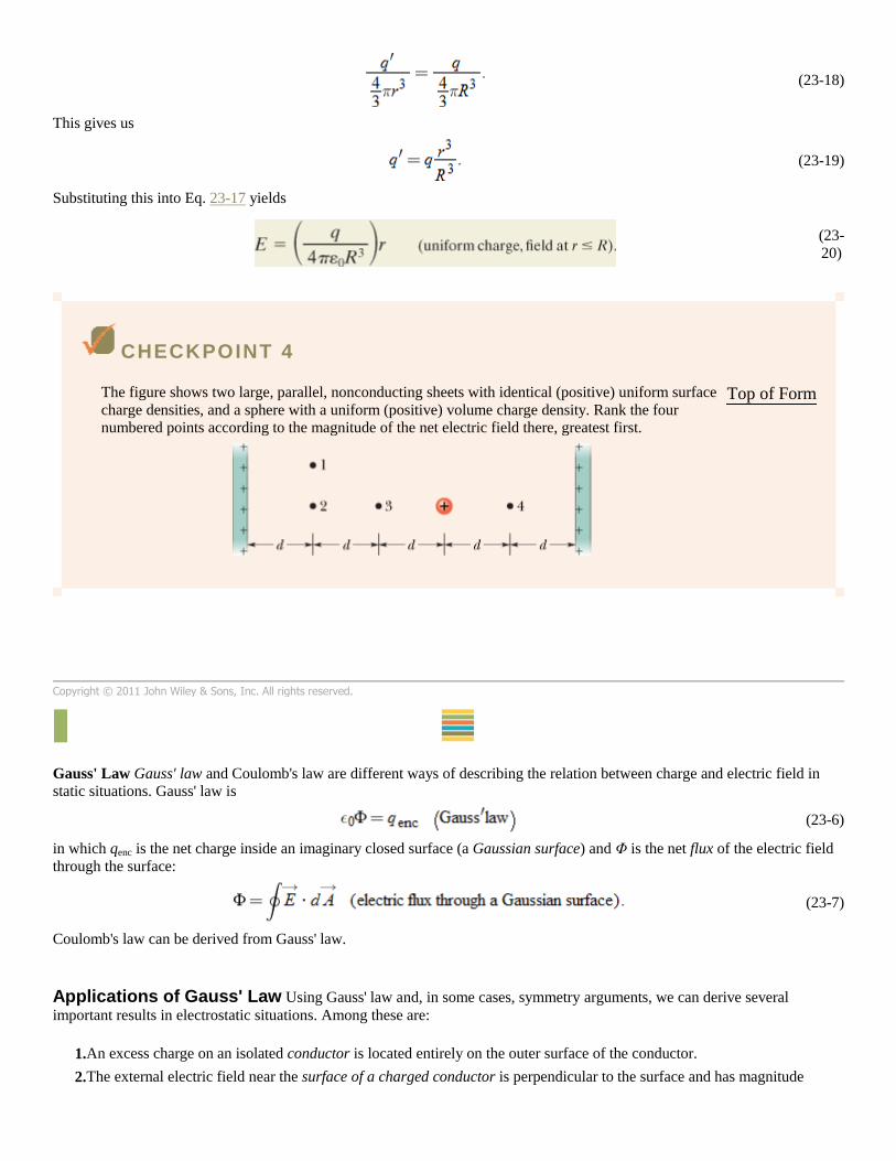
CHECKPOINT 4
The figure shows two large, parallel, nonconducting sheets with identical (positive) uniform surface
charge densities, and a sphere with a uniform (positive) volume charge density. Rank the four
numbered points according to the magnitude of the net electric field there, greatest first.
Top of Form
Copyright © 2011 John Wiley & Sons, Inc. All rights reserved.
REVIEW & SUMMARY
Gauss' Law Gauss' law and Coulomb's law are different ways of describing the relation between charge and electric field in
static situations. Gauss' law is
(23-6)
in which qenc is the net charge inside an imaginary closed surface (a Gaussian surface) and Φ is the net flux of the electric field
through the surface:
(23-7)
Coulomb's law can be derived from Gauss' law.
Applications of Gauss' Law Using Gauss' law and, in some cases, symmetry arguments, we can derive several
important results in electrostatic situations. Among these are:
1. An excess charge on an isolated conductor is located entirely on the outer surface of the conductor.
2. The external electric field near the surface of a charged conductor is perpendicular to the surface and has magnitude

(23-11)
Within the conductor, E = 0.
3. The electric field at any point due to an infinite line of charge with uniform linear charge density λ is perpendicular to the
line of charge and has magnitude
(23-12)
where r is the perpendicular distance from the line of charge to the point.
4. The electric field due to an infinite nonconducting sheet with uniform surface charge density σ is perpendicular to the
plane of the sheet and has magnitude
(23-13)
5. The electric field outside a spherical shell of charge with radius R and total charge q is directed radially and has
magnitude
(23-15)
Here r is the distance from the center of the shell to the point at which E is measured. (The charge behaves, for external
points, as if it were all located at the center of the sphere.) The field inside a uniform spherical shell of charge is exactly
zero:
(23-16)
6. The electric field inside a uniform sphere of charge is directed radially and has magnitude
(23-20)
Copyright © 2011 John Wiley & Sons, Inc. All rights reserved.
QUESTIONS
1
A surface has the area vector . What is the flux of a uniform electric field through the
area if the field is (a) and (b) ?
Top of Form
2 Figure 23-20 shows, in cross section, three solid cylinders, each of length L and uniform charge Q. Concentric with each
cylinder is a cylindrical Gaussian surface, with all three surfaces having the same radius. Rank the Gaussian surfaces
according to the electric field at any point on the surface, greatest first.
Figure 23-20 Question 2.
3 Figure 23-21 shows, in cross section, a central metal ball, two spherical metal shells, and three spherical
Gaussian surfaces of radii R, 2R, and 3R, all with the same center. The uniform charges on the three objects
are: ball, Q; smaller shell, 3Q; larger shell, 5Q. Rank the Gaussian surfaces according to the magnitude of the
electric field at any point on the surface, greatest first.
Top of Form
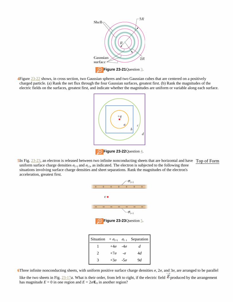
Figure 23-21 Question 3.
4 Figure 23-22 shows, in cross section, two Gaussian spheres and two Gaussian cubes that are centered on a positively
charged particle. (a) Rank the net flux through the four Gaussian surfaces, greatest first. (b) Rank the magnitudes of the
electric fields on the surfaces, greatest first, and indicate whether the magnitudes are uniform or variable along each surface.
Figure 23-22 Question 4.
5 In Fig. 23-23, an electron is released between two infinite nonconducting sheets that are horizontal and have
uniform surface charge densities σ(+) and σ(-), as indicated. The electron is subjected to the following three
situations involving surface charge densities and sheet separations. Rank the magnitudes of the electron's
acceleration, greatest first.
Figure 23-23 Question 5.
Situation + σ(+) σ(–) Separation
1 +4σ -4σ d
2 +7σ -σ 4d
3 +3σ -5σ 9d
Top of Form
6 Three infinite nonconducting sheets, with uniform positive surface charge densities σ, 2σ, and 3σ, are arranged to be parallel
like the two sheets in Fig. 23-17a. What is their order, from left to right, if the electric field produced by the arrangement
has magnitude E = 0 in one region and E = 2σ/ 0 in another region?
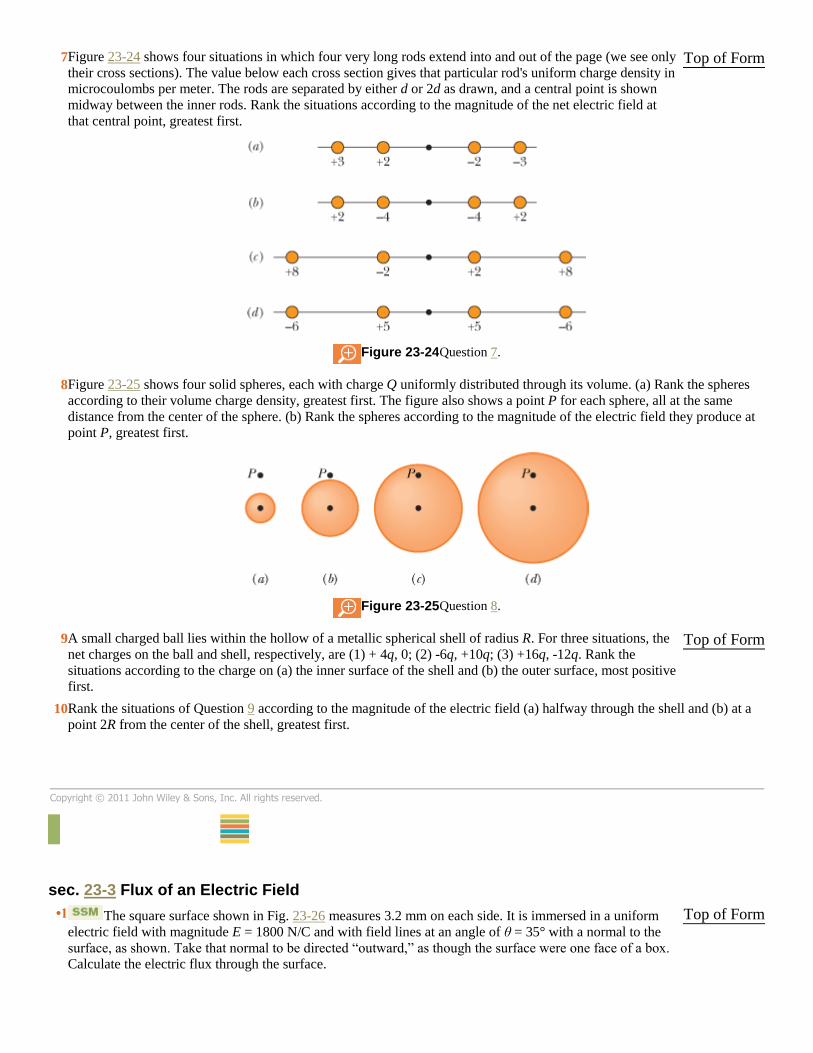
7 Figure 23-24 shows four situations in which four very long rods extend into and out of the page (we see only
their cross sections). The value below each cross section gives that particular rod's uniform charge density in
microcoulombs per meter. The rods are separated by either d or 2d as drawn, and a central point is shown
midway between the inner rods. Rank the situations according to the magnitude of the net electric field at
that central point, greatest first.
Figure 23-24 Question 7.
Top of Form
8 Figure 23-25 shows four solid spheres, each with charge Q uniformly distributed through its volume. (a) Rank the spheres
according to their volume charge density, greatest first. The figure also shows a point P for each sphere, all at the same
distance from the center of the sphere. (b) Rank the spheres according to the magnitude of the electric field they produce at
point P, greatest first.
Figure 23-25 Question 8.
9 A small charged ball lies within the hollow of a metallic spherical shell of radius R. For three situations, the
net charges on the ball and shell, respectively, are (1) + 4q, 0; (2) -6q, +10q; (3) +16q, -12q. Rank the
situations according to the charge on (a) the inner surface of the shell and (b) the outer surface, most positive
first.
Top of Form
10 Rank the situations of Question 9 according to the magnitude of the electric field (a) halfway through the shell and (b) at a
point 2R from the center of the shell, greatest first.
Copyright © 2011 John Wiley & Sons, Inc. All rights reserved.
PROBLEMS
sec. 23-3 Flux of an Electric Field
•1 The square surface shown in Fig. 23-26 measures 3.2 mm on each side. It is immersed in a uniform
electric field with magnitude E = 1800 N/C and with field lines at an angle of θ = 35° with a normal to the
surface, as shown. Take that normal to be directed “outward,” as though the surface were one face of a box.
Calculate the electric flux through the surface.
Top of Form
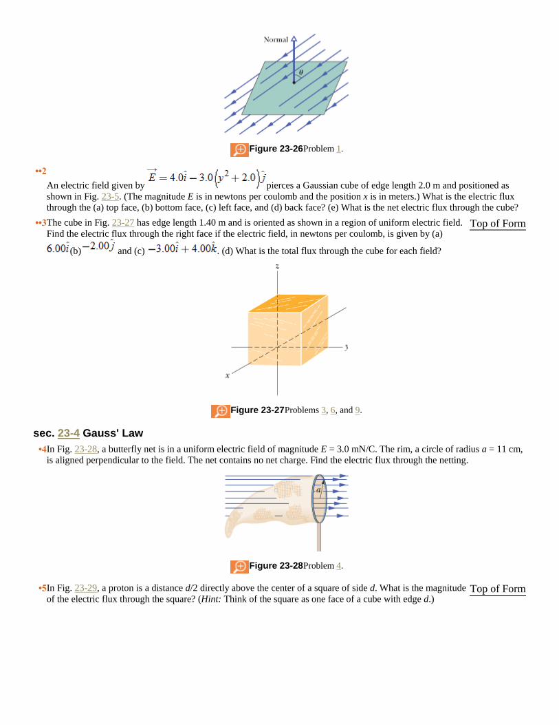
Figure 23-26 Problem 1.
••2
An electric field given by pierces a Gaussian cube of edge length 2.0 m and positioned as
shown in Fig. 23-5. (The magnitude E is in newtons per coulomb and the position x is in meters.) What is the electric flux
through the (a) top face, (b) bottom face, (c) left face, and (d) back face? (e) What is the net electric flux through the cube?
••3 The cube in Fig. 23-27 has edge length 1.40 m and is oriented as shown in a region of uniform electric field.
Find the electric flux through the right face if the electric field, in newtons per coulomb, is given by (a)
(b) and (c) . (d) What is the total flux through the cube for each field?
Figure 23-27 Problems 3, 6, and 9.
Top of Form
sec. 23-4 Gauss' Law
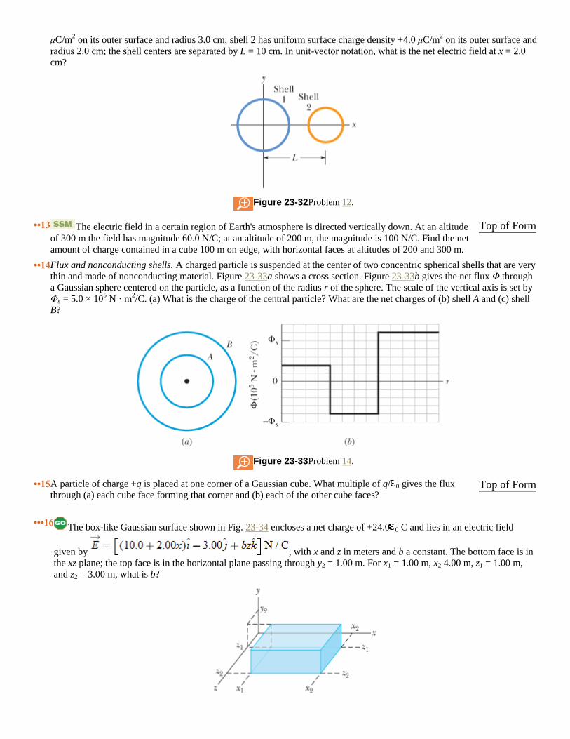
•4 In Fig. 23-28, a butterfly net is in a uniform electric field of magnitude E = 3.0 mN/C. The rim, a circle of radius a = 11 cm,
is aligned perpendicular to the field. The net contains no net charge. Find the electric flux through the netting.
Figure 23-28 Problem 4.
•5 In Fig. 23-29, a proton is a distance d/2 directly above the center of a square of side d. What is the magnitude
of the electric flux through the square? (Hint: Think of the square as one face of a cube with edge d.)
Top of Form
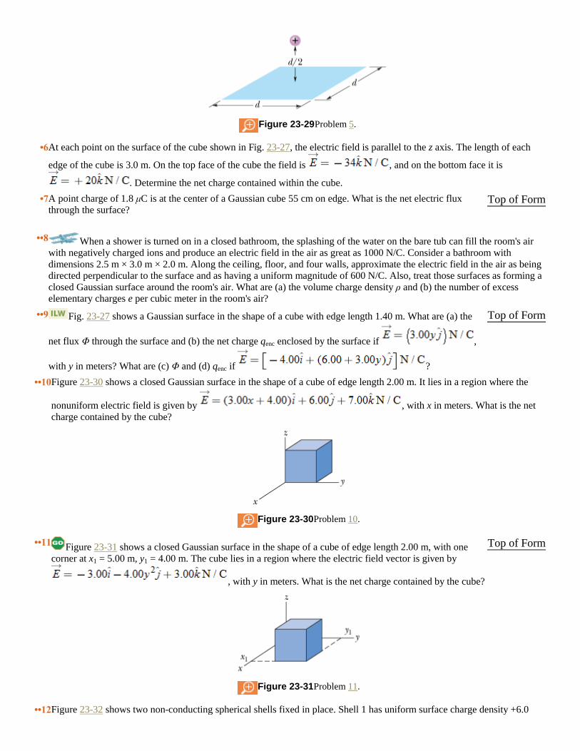
Figure 23-29 Problem 5.
•6 At each point on the surface of the cube shown in Fig. 23-27, the electric field is parallel to the z axis. The length of each
edge of the cube is 3.0 m. On the top face of the cube the field is , and on the bottom face it is
. Determine the net charge contained within the cube.
•7 A point charge of 1.8 μC is at the center of a Gaussian cube 55 cm on edge. What is the net electric flux
through the surface? Top of Form
••8 When a shower is turned on in a closed bathroom, the splashing of the water on the bare tub can fill the room's air
with negatively charged ions and produce an electric field in the air as great as 1000 N/C. Consider a bathroom with
dimensions 2.5 m × 3.0 m × 2.0 m. Along the ceiling, floor, and four walls, approximate the electric field in the air as being
directed perpendicular to the surface and as having a uniform magnitude of 600 N/C. Also, treat those surfaces as forming a
closed Gaussian surface around the room's air. What are (a) the volume charge density ρ and (b) the number of excess
elementary charges e per cubic meter in the room's air?
••9 Fig. 23-27 shows a Gaussian surface in the shape of a cube with edge length 1.40 m. What are (a) the
net flux Φ through the surface and (b) the net charge qenc enclosed by the surface if ,
with y in meters? What are (c) Φ and (d) qenc if ?
Top of Form
••10 Figure 23-30 shows a closed Gaussian surface in the shape of a cube of edge length 2.00 m. It lies in a region where the
nonuniform electric field is given by , with x in meters. What is the net
charge contained by the cube?
Figure 23-30 Problem 10.
••11 Figure 23-31 shows a closed Gaussian surface in the shape of a cube of edge length 2.00 m, with one
corner at x1 = 5.00 m, y1 = 4.00 m. The cube lies in a region where the electric field vector is given by
, with y in meters. What is the net charge contained by the cube?
Figure 23-31 Problem 11.
Top of Form
••12 Figure 23-32 shows two non-conducting spherical shells fixed in place. Shell 1 has uniform surface charge density +6.0
μC/m2 on its outer surface and radius 3.0 cm; shell 2 has uniform surface charge density +4.0 μC/m
2 on its outer surface and
radius 2.0 cm; the shell centers are separated by L = 10 cm. In unit-vector notation, what is the net electric field at x = 2.0
cm?
Figure 23-32 Problem 12.
••13 The electric field in a certain region of Earth's atmosphere is directed vertically down. At an altitude
of 300 m the field has magnitude 60.0 N/C; at an altitude of 200 m, the magnitude is 100 N/C. Find the net
amount of charge contained in a cube 100 m on edge, with horizontal faces at altitudes of 200 and 300 m.
Top of Form
••14 Flux and nonconducting shells. A charged particle is suspended at the center of two concentric spherical shells that are very
thin and made of nonconducting material. Figure 23-33a shows a cross section. Figure 23-33b gives the net flux Φ through
a Gaussian sphere centered on the particle, as a function of the radius r of the sphere. The scale of the vertical axis is set by
Φs = 5.0 × 10⁵ N · m
2/C. (a) What is the charge of the central particle? What are the net charges of (b) shell A and (c) shell
B?
Figure 23-33 Problem 14.
••15 A particle of charge +q is placed at one corner of a Gaussian cube. What multiple of q/ 0 gives the flux
through (a) each cube face forming that corner and (b) each of the other cube faces? Top of Form
•••16 The box-like Gaussian surface shown in Fig. 23-34 encloses a net charge of +24.0 0 C and lies in an electric field
given by , with x and z in meters and b a constant. The bottom face is in
the xz plane; the top face is in the horizontal plane passing through y2 = 1.00 m. For x1 = 1.00 m, x2 4.00 m, z1 = 1.00 m,
and z2 = 3.00 m, what is b?

Figure 23-34 Problem 16.
sec. 23-6 A Charged Isolated Conductor
•17 A uniformly charged conducting sphere of 1.2 m diameter has a surface charge density of 8.1 μC/m2.
(a) Find the net charge on the sphere. (b) What is the total electric flux leaving the surface of the sphere?
Top of Form
•18 The electric field just above the surface of the charged conducting drum of a photocopying machine has a magnitude E of
2.3 × 10⁵ N/C. What is the surface charge density on the drum?
•19 Space vehicles traveling through Earth's radiation belts can intercept a significant number of electrons. The
resulting charge buildup can damage electronic components and disrupt operations. Suppose a spherical
metal satellite 1.3 m in diameter accumulates 2.4 μC of charge in one orbital revolution. (a) Find the resulting
surface charge density. (b) Calculate the magnitude of the electric field just outside the surface of the
satellite, due to the surface charge.
Top of Form
•20 Flux and conducting shells. A charged particle is held at the center of two concentric conducting spherical shells. Figure
23-35a shows a cross section. Figure 23-35b gives the net flux Φ through a Gaussian sphere centered on the particle, as a
function of the radius r of the sphere. The scale of the vertical axis is set by Φs = 5.0 × 10⁵N · m
2/C. What are (a) the charge
of the central particle and the net charges of (b) shell A and (c) shell B?
Figure 23-35 Problem 20.
••21 An isolated conductor has net charge +10 × 10-6
C and a cavity with a point charge q = +3.0 × 10⁻⁶
C. What
is the charge on (a) the cavity wall and (b) the outer surface? Top of Form
sec. 23-7 Applying Gauss' Law: Cylindrical Symmetry
•22 An electron is released 9.0 cm from a very long nonconducting rod with a uniform 6.0 μC/m. What is the magnitude of the
electron's initial acceleration?
•23 (a) The drum of a photocopying machine has a length of 42 cm and a diameter of 12 cm. The electric field
just above the drum's surface is 2.3 × 10⁵ N/C. What is the total charge on the drum? (b) The manufacturer
wishes to produce a desktop version of the machine. This requires reducing the drum length to 28 cm and the
diameter to 8.0 cm. The electric field at the drum surface must not change. What must be the charge on this
new drum?
Top of Form
•24 Figure 23-36 shows a section of a long, thin-walled metal tube of radius R = 3.00 cm, with a charge per unit length of λ =
2.00 × 10⁻⁸
C/m. What is the magnitude E of the electric field at radial distance (a) r = R/2.00 and (b) r = 2.00R? (c) Graph E
versus r for the range r 0 to 2.00R.
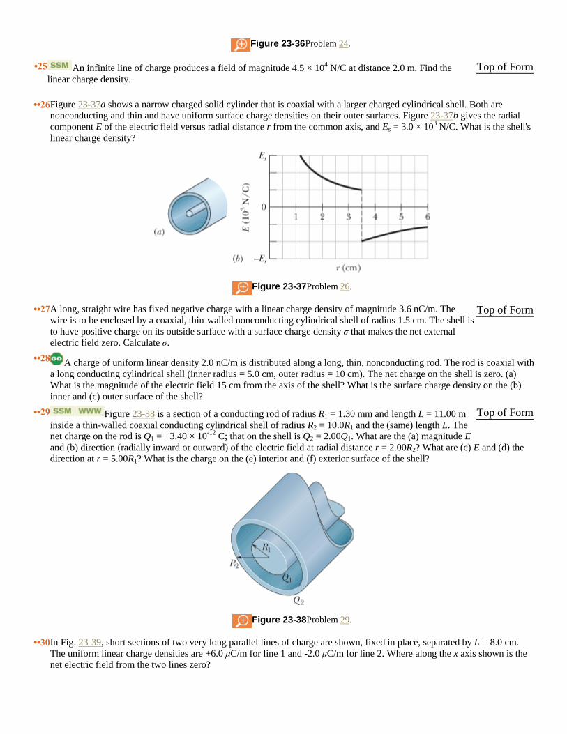
Figure 23-36 Problem 24.
•25 An infinite line of charge produces a field of magnitude 4.5 × 10⁴ N/C at distance 2.0 m. Find the
linear charge density.
Top of Form
••26 Figure 23-37a shows a narrow charged solid cylinder that is coaxial with a larger charged cylindrical shell. Both are
nonconducting and thin and have uniform surface charge densities on their outer surfaces. Figure 23-37b gives the radial
component E of the electric field versus radial distance r from the common axis, and Es = 3.0 × 10³ N/C. What is the shell's
linear charge density?
Figure 23-37 Problem 26.
••27 A long, straight wire has fixed negative charge with a linear charge density of magnitude 3.6 nC/m. The
wire is to be enclosed by a coaxial, thin-walled nonconducting cylindrical shell of radius 1.5 cm. The shell is
to have positive charge on its outside surface with a surface charge density σ that makes the net external
electric field zero. Calculate σ.
Top of Form
••28 A charge of uniform linear density 2.0 nC/m is distributed along a long, thin, nonconducting rod. The rod is coaxial with
a long conducting cylindrical shell (inner radius = 5.0 cm, outer radius = 10 cm). The net charge on the shell is zero. (a)
What is the magnitude of the electric field 15 cm from the axis of the shell? What is the surface charge density on the (b)
inner and (c) outer surface of the shell?
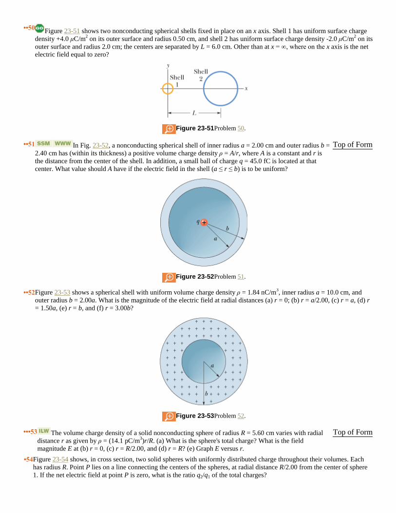
••29 Figure 23-38 is a section of a conducting rod of radius R1 = 1.30 mm and length L = 11.00 m
inside a thin-walled coaxial conducting cylindrical shell of radius R2 = 10.0R1 and the (same) length L. The
net charge on the rod is Q1 = +3.40 × 10⁻¹²
C; that on the shell is Q2 = 2.00Q1. What are the (a) magnitude E
and (b) direction (radially inward or outward) of the electric field at radial distance r = 2.00R2? What are (c) E and (d) the
direction at r = 5.00R1? What is the charge on the (e) interior and (f) exterior surface of the shell?
Figure 23-38 Problem 29.
Top of Form
••30 In Fig. 23-39, short sections of two very long parallel lines of charge are shown, fixed in place, separated by L = 8.0 cm.
The uniform linear charge densities are +6.0 μC/m for line 1 and -2.0 μC/m for line 2. Where along the x axis shown is the
net electric field from the two lines zero?

Figure 23-39 Problem 30.
••31 Two long, charged, thin-walled, concentric cylindrical shells have radii of 3.0 and 6.0 cm. The charge
per unit length is 5.0 × 10⁻⁶
C/m on the inner shell and -7.0 × 10⁻⁶
C/m on the outer shell. What are the (a)
magnitude E and (b) direction (radially inward or outward) of the electric field at radial distance r = 4.0 cm?
What are (c) E and (d) the direction at r = 8.0 cm?
Top of Form
••32 A long, nonconducting, solid cylinder of radius 4.0 cm has a nonuniform volume charge density ρ that is a function of
radial distance r from the cylinder axis: ρ = Ar2. For A = 2.5 μC/m
5, what is the magnitude of the electric field at (a) r = 3.0
cm and (b) r = 5.0 cm?
sec. 23-8 Applying Gauss' Law: Planar Symmetry
•33 In Fig. 23-40, two large, thin metal plates are parallel and close to each other. On their inner faces, the plates
have excess surface charge densities of opposite signs and magnitude 7.00 × 10⁻²²
C/m2. In unit-vector
notation, what is the electric field at points (a) to the left of the plates, (b) to the right of them, and (c)
between them?
Figure 23-40 Problem 33.
Top of Form
•34 In Fig. 23-41, a small circular hole of radius R = 1.80 cm has been cut in the middle of an infinite, flat, nonconducting
surface that has uniform charge density σ = 4.50 pC/m2. A z axis, with its origin at the hole's center, is perpendicular to the
surface. In unit-vector notation, what is the electric field at point P at z = 2.56 cm? (Hint: See Eq. 22-26 and use
superposition.)
Figure 23-41 Problem 34.
•35 Figure 23-42a shows three plastic sheets that are large, parallel, and uniformly charged. Figure 23-42b
gives the component of the net electric field along an x axis through the sheets. The scale of the vertical axis
is set by Es = 6.0 × 10⁵ N/C. What is the ratio of the charge density on sheet 3 to that on sheet 2?
Top of Form

Figure 23-42 Problem 35.
•36 Figure 23-43 shows cross sections through two large, parallel, non-conducting sheets with identical distributions of positive
charge with surface charge density σ = 1.77 × 10⁻²²
C/m2. In unit-vector notation, what is at points (a) above the sheets,
(b) between them, and (c) below them?
Figure 23-43 Problem 36.
•37 A square metal plate of edge length 8.0 cm and negligible thickness has a total charge of 6.0 ×
10-6
C. (a) Estimate the magnitude E of the electric field just off the center of the plate (at, say, a distance of
0.50 mm from the center) by assuming that the charge is spread uniformly over the two faces of the plate. (b)
Estimate E at a distance of 30 m (large relative to the plate size) by assuming that the plate is a point charge.
Top of Form
••38 In Fig. 23-44a, an electron is shot directly away from a uniformly charged plastic sheet, at speed vs = 2.0 × 10
5 m/s. The
sheet is nonconducting, flat, and very large. Figure 23-44b gives the electron's vertical velocity component v versus time t until the return to the launch point. What is the sheet's surface charge density?
Figure 23-44 Problem 38.
••39 In Fig. 23-45, a small, nonconducting ball of mass m = 1.0 mg and charge q = 2.0 × 10⁻⁸
C
(distributed uniformly through its volume) hangs from an insulating thread that makes an angle θ = 30° with
a vertical, uniformly charged nonconducting sheet (shown in cross section). Considering the gravitational
force on the ball and assuming the sheet extends far vertically and into and out of the page, calculate the surface charge
density σ of the sheet.
Top of Form

Figure 23-45 Problem 39.
••40 Figure 23-46 shows a very large nonconducting sheet that has a uniform surface charge density of σ = -2.00 μC/m2; it also
shows a particle of charge Q = 6.00 μC, at distance d from the sheet. Both are fixed in place. If d 0.200 m, at what (a)
positive and (b) negative coordinate on the x axis (other than infinity) is the net electric field of the sheet and particle
zero? (c) If d = 0.800 m, at what coordinate on the x axis is ?
Figure 23-46 Problem 40.
••41 An electron is shot directly toward the center of a large metal plate that has surface charge density -2.0 ×
10-6
C/m2. If the initial kinetic energy of the electron is 1.60 × 10
-17 J and if the electron is to stop (due to
electrostatic repulsion from the plate) just as it reaches the plate, how far from the plate must the launch
point be?
Top of Form
••42 Two large metal plates of area 1.0 m2 face each other, 5.0 cm apart, with equal charge magnitudes |q| but opposite signs.
The field magnitude E between them (neglect fringing) is 55 N/C. Find |q|.
••43 Figure 23-47 shows a cross section through a very large nonconducting slab of thickness d = 9.40 mm and
uniform volume charge density ρ = 5.80 fC/m3. The origin of an x axis is at the slab's center. What is the
magnitude of the slab's electric field at an x coordinate of (a) 0, (b) 2.00 mm, (c) 4.70 mm, and (d) 26.0 mm?
Figure 23-47 Problem 43.
Top of Form
sec. 23-9 Applying Gauss' Law: Spherical Symmetry
•44 Figure 23-48 gives the magnitude of the electric field inside and outside a sphere with a positive charge distributed
uniformly through-out its volume. The scale of the vertical axis is set by Es = 5.0 × 10⁷ N/C. What is the charge on the
sphere?

Figure 23-48 Problem 44.
•45 Two charged concentric spherical shells have radii 10.0 cm and 15.0 cm. The charge on the inner shell is
4.00 × 10⁻⁸
C, and that on the outer shell is 2.00 × 10⁻⁸
C. Find the electric field (a) at r = 12.0 cm and (b) at r
= 20.0 cm.
Top of Form
•46 A point charge causes an electric flux of -750 N · m2/C to pass through a spherical Gaussian surface of 10.0 cm radius
centered on the charge. (a) If the radius of the Gaussian surface were doubled, how much flux would pass through the
surface? (b) What is the value of the point charge?
•47 An unknown charge sits on a conducting solid sphere of radius 10 cm. If the electric field 15 cm from
the center of the sphere has the magnitude 3.0 × 10³ N/C and is directed radially inward, what is the net
charge on the sphere?
Top of Form
••48 A charged particle is held at the center of a spherical shell. Figure 23-49 gives the magnitude E of the electric field versus
radial distance r. The scale of the vertical axis is set by Es = 10.0 × 10⁷ N/C. Approximately, what is the net charge on the
shell?
Figure 23-49 Problem 48.
••49 In Fig. 23-50, a solid sphere of radius a = 2.00 cm is concentric with a spherical conducting shell of inner
radius b = 2.00a and outer radius c = 2.40a. The sphere has a net uniform charge q1 = +5.00 fC; the shell has
a net charge q2 = -q1. What is the magnitude of the electric field at radial distances (a) r = 0, (b) r = a/2.00,
(c) r = a, (d) r = 1.50a, (e) r = 2.30a, and (f) r = 3.50a? What is the net charge on the (g) inner and (h) outer
surface of the shell?
Figure 23-50 Problem 49.
Top of Form
••50 Figure 23-51 shows two nonconducting spherical shells fixed in place on an x axis. Shell 1 has uniform surface charge
density +4.0 μC/m2 on its outer surface and radius 0.50 cm, and shell 2 has uniform surface charge density -2.0 μC/m
2 on its
outer surface and radius 2.0 cm; the centers are separated by L = 6.0 cm. Other than at x = ∞, where on the x axis is the net
electric field equal to zero?
Figure 23-51 Problem 50.
••51 In Fig. 23-52, a nonconducting spherical shell of inner radius a = 2.00 cm and outer radius b =
2.40 cm has (within its thickness) a positive volume charge density ρ = A/r, where A is a constant and r is
the distance from the center of the shell. In addition, a small ball of charge q = 45.0 fC is located at that
center. What value should A have if the electric field in the shell (a ≤ r ≤ b) is to be uniform?
Figure 23-52 Problem 51.
Top of Form
••52 Figure 23-53 shows a spherical shell with uniform volume charge density ρ = 1.84 nC/m3, inner radius a = 10.0 cm, and
outer radius b = 2.00a. What is the magnitude of the electric field at radial distances (a) r = 0; (b) r = a/2.00, (c) r = a, (d) r
= 1.50a, (e) r = b, and (f) r = 3.00b?
Figure 23-53 Problem 52.
•••53 The volume charge density of a solid nonconducting sphere of radius R = 5.60 cm varies with radial
distance r as given by ρ = (14.1 pC/m3)r/R. (a) What is the sphere's total charge? What is the field
magnitude E at (b) r = 0, (c) r = R/2.00, and (d) r = R? (e) Graph E versus r.
Top of Form
•54 Figure 23-54 shows, in cross section, two solid spheres with uniformly distributed charge throughout their volumes. Each
has radius R. Point P lies on a line connecting the centers of the spheres, at radial distance R/2.00 from the center of sphere
1. If the net electric field at point P is zero, what is the ratio q2/q1 of the total charges?
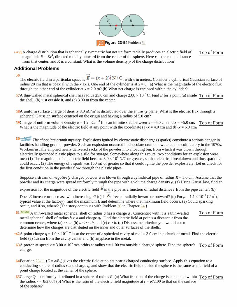
Figure 23-54 Problem 54.
•••55 A charge distribution that is spherically symmetric but not uniform radially produces an electric field of
magnitude E = Kr4, directed radially outward from the center of the sphere. Here r is the radial distance
from that center, and K is a constant. What is the volume density ρ of the charge distribution?
Top of Form
Additional Problems
56 The electric field in a particular space is , with x in meters. Consider a cylindrical Gaussian surface of
radius 20 cm that is coaxial with the x axis. One end of the cylinder is at x = 0. (a) What is the magnitude of the electric flux
through the other end of the cylinder at x = 2.0 m? (b) What net charge is enclosed within the cylinder?
57 A thin-walled metal spherical shell has radius 25.0 cm and charge 2.00 × 10⁻⁷
C. Find E for a point (a) inside
the shell, (b) just outside it, and (c) 3.00 m from the center. Top of Form
58 A uniform surface charge of density 8.0 nC/m2 is distributed over the entire xy plane. What is the electric flux through a
spherical Gaussian surface centered on the origin and having a radius of 5.0 cm?
59 Charge of uniform volume density ρ = 1.2 nC/m3 fills an infinite slab between x = -5.0 cm and x = +5.0 cm.
What is the magnitude of the electric field at any point with the coordinate (a) x = 4.0 cm and (b) x = 6.0 cm? Top of Form
60 The chocolate crumb mystery. Explosions ignited by electrostatic discharges (sparks) constitute a serious danger in
facilities handling grain or powder. Such an explosion occurred in chocolate crumb powder at a biscuit factory in the 1970s.
Workers usually emptied newly delivered sacks of the powder into a loading bin, from which it was blown through
electrically grounded plastic pipes to a silo for storage. Somewhere along this route, two conditions for an explosion were
met: (1) The magnitude of an electric field became 3.0 × 10⁶ N/C or greater, so that electrical breakdown and thus sparking
could occur. (2) The energy of a spark was 150 mJ or greater so that it could ignite the powder explosively. Let us check for
the first condition in the powder flow through the plastic pipes.
Suppose a stream of negatively charged powder was blown through a cylindrical pipe of radius R = 5.0 cm. Assume that the
powder and its charge were spread uniformly through the pipe with a volume charge density ρ. (a) Using Gauss' law, find an
expression for the magnitude of the electric field in the pipe as a function of radial distance r from the pipe center. (b)
Does E increase or decrease with increasing r? (c) Is directed radially inward or outward? (d) For ρ = 1.1 × 10⁻³
C/m3 (a
typical value at the factory), find the maximum E and determine where that maximum field occurs. (e) Could sparking
occur, and if so, where? (The story continues with Problem 70 in Chapter 24.)
61 A thin-walled metal spherical shell of radius a has a charge qa. Concentric with it is a thin-walled
metal spherical shell of radius b > a and charge qb. Find the electric field at points a distance r from the
common center, where (a) r < a, (b) a < r < b, and (c) r > b. (d) Discuss the criterion you would use to
determine how the charges are distributed on the inner and outer surfaces of the shells.
Top of Form
•62 A point charge q = 1.0 × 10⁻⁷
C is at the center of a spherical cavity of radius 3.0 cm in a chunk of metal. Find the electric
field (a) 1.5 cm from the cavity center and (b) anyplace in the metal.
63 A proton at speed v = 3.00 × 10⁵ m/s orbits at radius r = 1.00 cm outside a charged sphere. Find the sphere's
charge. Top of Form
64 Equation 23-11 (E = σ/ 0) gives the electric field at points near a charged conducting surface. Apply this equation to a
conducting sphere of radius r and charge q, and show that the electric field outside the sphere is the same as the field of a
point charge located at the center of the sphere.
65 Charge Q is uniformly distributed in a sphere of radius R. (a) What fraction of the charge is contained within
the radius r = R/2.00? (b) What is the ratio of the electric field magnitude at r = R/2.00 to that on the surface
of the sphere?
Top of Form
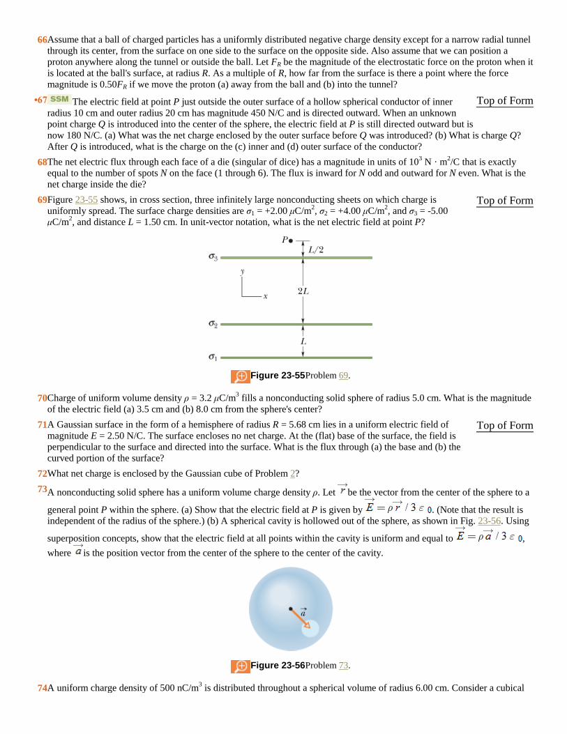
66 Assume that a ball of charged particles has a uniformly distributed negative charge density except for a narrow radial tunnel
through its center, from the surface on one side to the surface on the opposite side. Also assume that we can position a
proton anywhere along the tunnel or outside the ball. Let FR be the magnitude of the electrostatic force on the proton when it
is located at the ball's surface, at radius R. As a multiple of R, how far from the surface is there a point where the force
magnitude is 0.50FR if we move the proton (a) away from the ball and (b) into the tunnel?
•67 The electric field at point P just outside the outer surface of a hollow spherical conductor of inner
radius 10 cm and outer radius 20 cm has magnitude 450 N/C and is directed outward. When an unknown
point charge Q is introduced into the center of the sphere, the electric field at P is still directed outward but is
now 180 N/C. (a) What was the net charge enclosed by the outer surface before Q was introduced? (b) What is charge Q?
After Q is introduced, what is the charge on the (c) inner and (d) outer surface of the conductor?
Top of Form
68 The net electric flux through each face of a die (singular of dice) has a magnitude in units of 103 N · m
2/C that is exactly
equal to the number of spots N on the face (1 through 6). The flux is inward for N odd and outward for N even. What is the
net charge inside the die?
69 Figure 23-55 shows, in cross section, three infinitely large nonconducting sheets on which charge is
uniformly spread. The surface charge densities are σ1 = +2.00 μC/m2, σ2 = +4.00 μC/m
2, and σ3 = -5.00
μC/m2, and distance L = 1.50 cm. In unit-vector notation, what is the net electric field at point P?
Figure 23-55 Problem 69.
Top of Form
70 Charge of uniform volume density ρ = 3.2 μC/m3 fills a nonconducting solid sphere of radius 5.0 cm. What is the magnitude
of the electric field (a) 3.5 cm and (b) 8.0 cm from the sphere's center?
71 A Gaussian surface in the form of a hemisphere of radius R = 5.68 cm lies in a uniform electric field of
magnitude E = 2.50 N/C. The surface encloses no net charge. At the (flat) base of the surface, the field is
perpendicular to the surface and directed into the surface. What is the flux through (a) the base and (b) the
curved portion of the surface?
Top of Form
72 What net charge is enclosed by the Gaussian cube of Problem 2?
73 A nonconducting solid sphere has a uniform volume charge density ρ. Let be the vector from the center of the sphere to a
general point P within the sphere. (a) Show that the electric field at P is given by . (Note that the result is
independent of the radius of the sphere.) (b) A spherical cavity is hollowed out of the sphere, as shown in Fig. 23-56. Using
superposition concepts, show that the electric field at all points within the cavity is uniform and equal to ,
where is the position vector from the center of the sphere to the center of the cavity.
Figure 23-56 Problem 73.
74 A uniform charge density of 500 nC/m3 is distributed throughout a spherical volume of radius 6.00 cm. Consider a cubical

Gaussian surface with its center at the center of the sphere. What is the electric flux through this cubical surface if its edge
length is (a) 4.00 cm and (b) 14.0 cm?
75 Figure 23-57 shows a Geiger counter, a device used to detect ionizing radiation, which causes ionization of
atoms. A thin, positively charged central wire is surrounded by a concentric, circular, conducting cylindrical
shell with an equal negative charge, creating a strong radial electric field. The shell contains a low-pressure
inert gas. A particle of radiation entering the device through the shell wall ionizes a few of the gas atoms.
The resulting free electrons (e) are drawn to the positive wire. However, the electric field is so intense that, between
collisions with gas atoms, the free electrons gain energy sufficient to ionize these atoms also. More free electrons are
thereby created, and the process is repeated until the electrons reach the wire. The resulting “avalanche” of electrons is
collected by the wire, generating a signal that is used to record the passage of the original particle of radiation. Suppose that
the radius of the central wire is 25 μm, the inner radius of the shell 1.4 cm, and the length of the shell 16 cm. If the electric
field at the shell's inner wall is 2.9 × 10⁴ N/C, what is the total positive charge on the central wire?
Figure 23-57 Problem 75.
Top of Form
76 Charge is distributed uniformly throughout the volume of an infinitely long solid cylinder of radius R. (a) Show that, at a
distance r < R from the cylinder axis, where ρ is the volume charge density. (b) Write an expression for E when
r > R.
77 A spherical conducting shell has a charge of -14 μC on its outer surface and a charged particle in its
hollow. If the net charge on the shell is -10 μC, what is the charge (a) on the inner surface of the shell and (b)
of the particle?
Top of Form
78 A charge of 6.00 pC is spread uniformly throughout the volume of a sphere of radius r = 4.00 cm. What is the magnitude of
the electric field at a radial distance of (a) 6.00 cm and (b) 3.00 cm?
79 Water in an irrigation ditch of width w = 3.22 m and depth d = 1.04 m flows with a speed of 0.207 m/s. The
mass flux of the flowing water through an imaginary surface is the product of the water's density (1000
kg/m3) and its volume flux through that surface. Find the mass flux through the following imaginary
surfaces: (a) a surface of area wd, entirely in the water, perpendicular to the flow; (b) a surface with area
3wd/2, of which wd is in the water, perpendicular to the flow; (c) a surface of area wd/2, entirely in the water, perpendicular
to the flow; (d) a surface of area wd, half in the water and half out, perpendicular to the flow; (e) a surface of area wd,
entirely in the water, with its normal 34.0° from the direction of flow.
Top of Form
80 Charge of uniform surface density 8.00 nC/m2 is distributed over an entire xy plane; charge of uniform surface density 3.00
nC/m2 is distributed over the parallel plane defined by z = 2.00 m. Determine the magnitude of the electric field at any point
having a z coordinate of (a) 1.00 m and (b) 3.00 m.
81 A spherical ball of charged particles has a uniform charge density. In terms of the ball's radius R, at what
radial distances (a) inside and (b) outside the ball is the magnitude of the ball's electric field equal to of the
maximum magnitude of that field?
Top of Form

82 A free electron is placed between two large, parallel, nonconducting plates that are horizontal and 2.3 cm apart. One
plate has a uniform positive charge; the other has an equal amount of uniform negative charge. The force on the electron due
to the electric field between the plates balances the gravitational force on the electron. What are (a) the magnitude of the
surface charge density on the plates and (b) the direction (up or down) of ?
Copyright © 2011 John Wiley & Sons, Inc. All rights reserved.