one-dimensional simulation with the fdtd method...one-dimensional simulation with the fdtd method...
TRANSCRIPT

One-Dimensional Simulationwith the FDTD Method
This chapter is a step-by-step introduction to the FDTD method. It begins with the simplestpossible problem, the simulation of a pulse propagating in free space in one dimension. Thisexample is used to illustrate the FDTD formulation. Subsequent sections lead to the formulationfor more complicated media
1.1 ONE-DIMENSIONAL FREE SPACE FORMULATION
The time-dependent Maxwell's curl equations in free space are
di = 70VxH (1-la)
^ = ~VxB. (1.1b)dt /X0
E and H are vectors in three dimensions, so in general, Eq. (1.1a) and (1.1b) represent threeequations each. We will start with a simple one-dimensional case using only Ex and Hy, soEq. (1.1a) and (1.1b) become
^ = - - L ^ . (1.2b)dt /xo 3z
These are the equations of a plane wave with the electric field oriented in the x direction, themagnetic field oriented in the y direction, and traveling in the z direction.
Taking the central difference approximations for both the temporal and spatial derivativesgives
Ei+y2(k) - Enx~
l/2(k) 1 Hny{k + 1/2) - H>;{k - 1/2)
_ (i.3a)At SQ Ax
H^\k + 1/2) - H;(k + 1/2) _ 1 Enx+l/2(k + 1) - EZ+l/2(k)
At /x0 Ax
1
1
dEX _ 1 dHy
dt £Q dz
dHy 1 3EX
dt fi0 dz '
(1.2a)
(1.3b)
x E.

Chapter 1 • One-Dimensional Simulation with the FDTD Method
In these two equations, time is specified by the superscripts, i.e., "w" actually means a timet = At • n. Remember, we have to discretize everything for formulation into the computer.The term '7z + 1" means one time step later. The terms in parentheses represent distance,i.e., "&" actually means the distance z = Ax • k. (It might seem more sensible to use Az asthe incremental step, since in this case we are going in the z direction. However, Ax is socommonly used for a spatial increment that I will use Ax.) The formulation of Eq. (1.3a) and(1.3b) assumes that the E and H fields are interleaved in both space and time. H uses thearguments k + 1/2 and k — 1/2 to indicate that the H field values are assumed to be locatedbetween the E field values. This is illustrated in Fig. 1.1. Similarly, the n + 1/2 or n — 1/2superscript indicates that it occurs slightly after or before n, respectively.
2
Figure 1.1 Interleaving of the E and H fields in space and time in the FDTD formulation.To calculate Hy(k +1 /2 ) , for instance, the neighboring values of Ex at k andk + 1 are needed. Similarly, to calculate Ex (k + 1), the value of Hy at k + 1/2and k + 1 1/2 are needed.
Eq. (1.3a) and (1.3b) can be rearranged in an iterative algorithm:
E$+l'2(k) = Enx-
lt\k) - -^—[H;(k + 1/2) - H»(k - 1/2)] (1.4a)co * iSX
H$+1(k + 1/2) = #;(* + 1/2) ^—[Enx+1/2(k + 1) - En
x+ll2(k)}. (1.4b)
fJyQ ' L\X
Notice that the calculations are interleaved in both space and time. In Eq. (1.4a), for example,the new value of Ex is calculated from the previous value of Ex and the most recent values ofHy. This is the fundamental paradigm of the finite-difference time-domain (FDTD) method [ 1 ].
Eqs. (1.4a) and (1.4b) are very similar, but because s0 and /x0 differ by several ordersof magnitude, Ex and Hy will differ by several orders of magnitude. This is circumvented bymaking the following change of variables [2]:
£ = A / ^ £ . (1.5)V Mo
Substituting this into Eqs. (1.4a) and (1.4b) gives
E?l'2(k) = Enx-
l/\k) - — L - ^ w ^ j f c + 1/2) - Hn(k - 1/2)] (1.6a)^/eofio Ax y y
H»+\k + 1/2) = H"(k + 1/2) - _L_-£?.[EJ+i/2(jfc + i) _ Enx+l'\k)] (1.6b)
^/SofiQ Ax
rn-l/2
k-2 k-\
TJ n
k k+l k + 2
£ + 2 1/2k+l 111£+1/2k-\l2k~\ 1/2
r- n+1/2^x
k-2 k-\ k k+l k + 2

Figure 1.2 FDTD simulation of a pulse in free space after 100 time steps. The pulseoriginated in the center and travels outward.
Section 1 . 1 B One-Dimensional Free Space Formulation 3
Once the cell size Ax is chosen, then the time step At is determined by
Ax&* = - (1.7)
2 • Co
where c0 is the speed of light in free space. (The reason for this will be explained later.)Therefore,
1 At Ax 12 - c 0 1-7=— = c0 = - (1.8)V oMo A* Ax 2
Rewriting Eqs. (1.6a) and (1.6b) in C computer code gives the following:
e x [ k ] = ex [k ] + 0 . 5 * ( h y [ k - l ] - hy [k] ) (1.9a)hy[k ] = hy[k ] + 0 . 5 * ( ex [k] - e x [ k + l ] ) . (1.9b)
Note that the n o r n + l / 2 o r n - l / 2 i n the superscripts is gone. Time is implicit in theFDTD method. In Eq. (1.9a), the ex on the right side of the equal sign is the previous valueat n — 1/2, and the ex on the left side is the new value, n + 1/2, which is being calculated.Position, however, is explicit. The only difference is that k + 1/2 and k - 1/2 are rounded offto k and k — 1 in order to specify a position in an array in the program.
The program fdld_l.l.c at the end of the chapter is a simple one-dimensional FDTDprogram. It generates a Gaussian pulse in the center of the problem space, and the pulsepropagates away in both directions as seen in Fig. 1.2. The Ex field is positive in bothdirections, but the Hy field is negative in the negative direction. The following things areworth noting about the program:
1. The Ex and Hy values are calculated by separate loops, and they employ the inter-leaving described above.
2. After the Ex values are calculated, the source is calculated. This is done by simplyspecifying a value of Ex at the point k = kc, and overriding what was previouslycalculated. This is referred to as a "hard source," because a specific value is imposedon the FDTD grid.
r=ioohf
1
4 0
—i0 20 40 60 80 100 120 140 160 180 200
0 20 40 60 80 100 120 140 160 180 200
FDTD cells
1
0
-1
*T

4 Chapter 1 • One-Dimensional Simulation with the FDTD Method
PROBLEM SET 1.1
1. Get the program fdld_l.l.c running. What happens when the pulse hits the end of the array?Why?
2. Modify the program so it has two sources, one at kc - 2 0 and one at kc + 2 0 (Notice thatkc is the center of the problem space). What happens when the pulses meet? Explain this frombasic EM theory.
3. Instead of Ex as the source, use Hy at k = kc as the source. What difference does it make?Try a two-point magnetic source at kc - 1 and kc such that hy [kc-1] = -hy [kc ] .What does this look like? What does it correspond to physically?
1.2 STABILITY AND THE FDTD METHOD
Let us return to the discussion of how we determine the time step. An electromagnetic wavepropagating in free space cannot go faster than the speed of light. To propagate a distanceof one cell requires a minimum time of At — AX/CQ. When we get to two-dimensionalsimulation, we have to allow for the propagation in the diagonal direction, which brings thetime requirement to At = AJC/(\/2CO). Obviously, three-dimensional simulation requiresAt = Ax/(V3co). This is summarized by the well-known "Courant Condition" [3, 4]:
A*At < 1 (U0)
y/n ' Co
where n is the dimension of the simulation. Unless otherwise specified, throughout this bookwe will determine At by
A* = ^ . (1.11)
This is not necessarily the best formula; however, we will use it for simplicity.
PROBLEM SET 1.2
1. In fdld_l.l.c, go to the two governing equations, Eq. (1.9a) and (1.9b), and change the factor0.5 to 1.0. What happens? Change it to 1.1. Now what happens? Change it to .25 and seewhat happens.
1.3 THE ABSORBING BOUNDARY CONDITION IN ONEDIMENSION
Absorbing boundary conditions are necessary to keep outgoing E and H fields from beingreflected back into the problem space. Normally, in calculating the E field, we need to knowthe surrounding H values; this is a fundamental assumption of the FDTD method. At the edgeof the problem space we will not have the value to one side. However, we have an advantagebecause we know there are no sources outside the problem space. Therefore, the fields at theedge must be propagating outward. We will use these two facts to estimate the value at theend by using the value next to it [5].
Suppose we are looking for a boundary condition at the end where k = 0. If a wave isgoing toward a boundary in free space, it is traveling at c0, the speed of light. So in one timestep of the FDTD algorithm, it travels
Az Axdistance = CQ • At = c0 - — = — .
c0 2

Section 1.4 • Propagation in a Dielectric Medium 5
This equation basically explains that it takes two time steps for a wave front to cross one cell.So a common sense approach tells us that an acceptable boundary condition might be
Enx{0) = En-2(\). (1.12)
It is relatively easy to implement this. Simply store a value of Ex{\) for two time steps, andthen put it in Ex(0). Boundary conditions such as these have been implemented at both endsof the Ex array in the program fdld_l .2.c. (In the printout labeled fdld_l .2.c at the end of thechapter, the entire program hasn't been reproduced, only those parts which are different fromfdld_l.l.c. Furthermore, key points are highlighted in boldface.) Figure 1.3 shows the resultsof a simulation using fdld_1.2.c. A pulse that originates in the center propagates outward andis absorbed without reflecting anything back into the problem space.
Figure 1.3 Simulation of an FDTD program with absorbing boundary conditions. Noticethat the pulse is absorbed at the edges without reflecting anything back.
PROBLEM SET 1.3
1. The program fdld_1.2.c has absorbing boundary conditions at both ends. Get this programrunning and test it to ensure the boundary conditions are completely absorbing the pulse.
1.4 PROPAGATION IN A DIELECTRIC MEDIUM
In order to simulate a medium with a dielectric constant other than one, which corresponds tofree space, we have to add the relative dielectric constant sr to Maxwell's equations:
*1 = J _ v x H (1.13a)dt sr£o
^ = -ivx£. (1.13b)dt MO
ttT
l
0.5
0
r=ioo
20 40 60 80 100 120 140 160 180
tf
1
0.5
0
T=225
20 40 60 80 100 120 140 160 180
bf
1
0.5
0
7=250
20 40 60 80 100 120 140 160 180
FDTD cells

6 Chapter 1 • One-Dimensional Simulation with the FDTD Method
We will stay with our one-dimensional example and make the change of variables in Eq. (1.5),
dEx(t) _ 1 dHy{t)
dt £rVe0M0 dz
dHy(t) = 1 dEx(t)
dt V OMO dz
and then go to the finite difference approximations
Enx+
l/2(k) - Enx-
V\k) 1 HHk + 1/2) - HHk + 1/2)— = • — (1.14a)
H«+l(k + 1/2) - H^jk + 1/2) _ 1 Enx+l/2(k + 1) - En
x+l/2(k)
Ar fiQ Ax
From the previous section
1 A* _ 1
V^oMo Ax 2 '
so Eq. (1.14) becomes
Enx+x/2(k) = En
x+l/2(k) + — [ / / " ( / : + 1/2) - Hn(k + 1/2)] (1.15a)
er y y
Hny+\k + 1/2) = H;(k + 1/2) - ^[E^2(k + 1) - £J+1/2(Jfc)]. (1.15b)
From these we can get the computer equations
ex[k] = ex[k] + cb[k]*(hy[k-l ] - hy[k] ) (1.16a)hy[k] = hy[k] + 0.5* (ex [k] - ex[k+l] ) , (1.16b)
where
cb[k] = . 5 / e p s i l o n (1.17)
over those values of k which specify the dielectric material.The program fdld_1.3.c simulates the interaction of a pulse traveling in free space until
it strikes a dielectric medium. The medium is specified by the parameter cb in Eq. (1.17).Figure 1.4 shows the result of a simulation with a dielectric medium having a relative dielectricconstant of 4. Note that a portion of the pulse propagates into the medium and a portion isreflected, in keeping with basic EM theory [6].
PROBLEM SET 1.4
1. The program fdld_1.3.c simulates a problem partly containing free space and partly dielectricmaterial. Run this program and duplicate the results of Fig. 1.4.
2. Look at the relative amplitudes of the reflected and transmitted pulses. Are they correct? Checkthem by calculating the reflection and transmission coefficients. (See the appendix at the endof this chapter.)
3. Still using a dielectric constant of 4, let the transmitted pulse propagate until it hits the far rightwall. What happens? What could you do to correct this?
(*)SrJeolM) Ax
(1.14b)
1/2
l'\k

Section 1.5 • Simulating Different Sources
Figure 1.4 Simulation of a pulse striking a dielectric material with a dielectric constant of4. The source originates at cell number 5.
1.5 SIMULATING DIFFERENT SOURCES
In the first two programs, a source is assigned a value to Ex; this is referred to as a hard source.In fdld_1.3.c, however, a value is added to Ex at a certain point; this is called a soft source.The reason is that with a hard source, a propagating pulse will see that value and be reflected,because a hard value of Ex looks like a metal wall to FDTD. With the soft source, a propagatingpulse will just pass through.
Up until now, we have been using a Gaussian pulse as the source. It is very easy toswitch to a sinusoidal source. Just replace the parameter pulse with the following:
pulse = sin[2*pi*freq_in*dt*T]
ex[5] = ex[5] + pulse.
The parameter/r£#_j>z determines the frequency of the wave. This source is used in the programfdld_1.4.c. Figure 1.5 shows the same dielectric medium problem with a sinusoidal source.A frequency of 700 MHz is used. Notice that the simulation was stopped before the wavereached the far right side. Remember that we have an absorbing boundary condition, but itwas only for free space!
Note that in fdld_1.4.c the cell size ddx and the time step d t are specified explicitly.We do this because we need d t in the calculation of pulse. The cell size ddx is only specifiedbecause it is needed to calculate d t from Eq. (1.7).
7
7=100 Eps = 4tf
1
0.5
0
-0.520 40 60 80 100 120 140 160 180 200
fcf
1
0.5
0
-0.5
T=220 Eps = 4
20 40 60 80 100 120 140 160 180 200
fcf
1
0.5
0
-0.5
T=320 Eps = 4
20 40 60 80 100 120 140 160 180 200
kT
l
0.5
0
-0.5
T=440 Eps = 4
20 40 60 80 100 120 140 160 180 200FDTD cells

Chapter 1 • One-Dimensional Simulation with the FDTD Method
Figure 1.5 Simulation of a propagating sinusoidal wave of 700 MHz striking a mediumwith a relative dielectric constant of 4.
8
PROBLEM SET 1.5
1. Modify your program fdld_1.3.c to simulate the sinusoidal source (see fdld__1.4.c).
2. Keep increasing your incident frequency from 700 MHz upward at intervals of 300 MHz. Whathappens?
3. A type of propagating wave function that is of great interest in areas such as optics is the"wave packet," which is a sinusoidal function in a Gaussian envelope. Modify your programto simulate a wave packet.
1.6 DETERMINING CELL SIZE
Choosing the cell size to be used in an FDTD formulation is similar to any approximationprocedure: enough sampling points must be taken to ensure that an adequate representation ismade. The number of points per wavelength is dependent on many factors [3, 4]. However,a good rule of thumb is 10 points per wavelength. Experience has shown this to be adequate,with inaccuracies appearing as soon as the sampling drops below this rate.
Naturally, we must use a worst-case scenario. In general, this will involve looking atthe highest frequencies we are simulating and determining the corresponding wavelength. Forinstance, suppose we are running simulations at 400 MHz. In free space, EM energy willpropagate at the wavelength
c0 3 x 10⁸ m/secX° = 400MHz" = 4 T l 0 ^ e ^ " = " 7 5 m " ( L 1 8 )
If we were only simulating free space we could choose
Ax = k0/10 = 1.5cm.
However, if we are simulating EM propagation in biological tissues, for instance, we mustlook at the wavelengths in the tissue with the highest dielectric constant, because this will havethe corresponding shortest wavelength. For instance, muscle has a relative dielectric constantof about 50 at 400 MHz, so
co/V5O .424 x 108 m/sec
*" = mum = 4x10* sec-' = 1 0 ' 6 c m ' (U9>and we would probably select a cell size of one centimeter.
20 40 60 80 100 120 140 160 180
FDTD cells
tf
1
0
-1
T=42y
20 40 60 80 100 120 140 160 180
Eps = 4
T/= 150 Eps = 4
tf
1
0
-1
.75 m. (1.18)

Section 1.7 • Propagation in a Lossy Dielectric Medium 9
PROBLEM SET 1.6
1. Simulate a 3-GHz sine wave impinging on a material with a dielectric constant of sr = 20.
1.7 PROPAGATION IN A LOSSY DIELECTRIC MEDIUM
So far, we have simulated EM propagation in free space or in simple media that are specifiedby the relative dielectric constant sr. However, there are many media that also have a lossterm specified by the conductivity. This loss term results in the attenuation of the propagatingenergy.
Once more we will start with the time-dependent Maxwell's curl equations, but we willwrite them in a more general form, which will allow us to simulate propagation in media thathave conductivity:
s— = V x H - J (1.20a)ot
^E. = _ J_v x E. (1.20b)dt jiQ
J is the current density, which can also be written
J = cr-E,
where a is the conductivity. Putting this into Eq. (1.20a) and dividing through by the dielectricconstant we get
3E - l Vxff ° Edt So£r £QSV
We now revert to our simple one-dimensional equation:
dEAt) __ 1 dHy(t) a- - — • £Lx{t),dt £r£o dZ Sr£0
and make the change of variable in Eq. (1.5), which gives
? M = • ^ _ J L j , ( 1 | (1.21a)
!MU L_.^2. (i.2ib)dt V OMO dZ
Next take the finite difference approximations for both the temporal and spatial derivativessimilar to Eq. (1.3a):
Ef^l/2(k)-Enx-
1/2(k) __ 1 H;(k + 1/2)-HfQc-1/2)
Ar ~ erjeofio Ax
a ff+1/2(fc) + £r1/2(fc)ereo 2
Notice that the last term in Eq. (1.21a) is approximated as the average across two time stepsin Eq. (1.22). From the previous section
1 At _ 1
y/SofJLQ AX 2 '
dt GrJeoPO $Z £r£Q
\k) 1/2)
(1.22)

10 Chapter 1 • One-Dimensional Simulation with the FDTD Method
so Eq. (1.22) becomes
^+./2 ( t )r1+AL£i=Jg--./2 (Jt )r1_AL£]L 2ere0 J L 2£r£o J
- —[H;(k + 1/2) - Hny(k - 1/2)]
or
K+l/\k) = j—^i^Enx-
{/2(k) l/2Afa\[Hy(k + 1 / 2 ) " H " ( * " 1 / 2 ) L
\ 2£r£0 / r V 2exe0 /
From these we can get the computer equations
ex[k] = ca[k]*ex[k] + cb [k] *( hy[k-l] - hy [k] ) (1.23a)
hy[k] = hy[k] + 0.5* ( ex [k] - ex[k+l] ) , (1.23b)
where
eaf = dt*sigma/(2*epsz*epsi lon) (1.24a)ca[k] = (1 . - e a f ) / ( I . + eaf) (1.24b)cb[k] =0 .5 / (eps i lon* (1 . + e a f ) ) . (1.24c)
The program fdld_l .5.c simulates a sinusoidal wave hitting a lossy medium that has a dielectricconstant of 4 and a conductivity of 0.04. The pulse is generated at the far left side and propagatesto the right. This is illustrated in Fig. 1.6. Notice that the waveform in the medium is absorbedbefore it hits the boundary, so we don't have to worry about absorbing boundary conditions.
Figure 1.6 Simulation of a propagating sinusoidal wave striking a lossy dielectric materialwith a dielectric constant of 4 and a conductivity of 0.04 (S/m). The source is700 MHz, and originates at cell number 5.
PROBLEM SET 1.7
1. Run program fdld_1.5.c to simulate a complex dielectric material. Duplicate the results ofFig. 1.6.
2. Verify that your calculation of the sine wave in the lossy dielectric is correct, i.e., it is the correctamplitude going into the slab, and then it attenuates at the proper rate. You can best do this bywriting a little program that calculates the parameters given in the appendix of this chapter.
3. How would you write an absorbing boundary condition for a lossy material?
4. Simulate a pulse hitting a metal wall. This is very easy to do, if you remember that metal has avery high conductivity. For the complex dielectric, just use o — I.e6, or any large number. (Itdoes not have to be the correct conductivity of the metal, just very large.) What does this do tothe FDTD parameters ca and cbl What result does this have for the field parameters Ex andHyl If you didn't want to specify dielectric parameters, how else could you simulate metal inan FDTD program?
Eps = 4r=soofcf
1
0
20 40 60 80 100 120 140 160 180FDTD cells
Cond = 0.04
1 -At -a
2ere0
1 +E"x-
l/2(k)
£ ,
1/2
£,- 1 +-[#;(* +1/2)-#;(*-1/2)].

References 11
APPENDIX 1.A
When a plane wave traveling in medium 1 strikes a medium 2, the fraction that is reflected isgiven by the reflection coefficient F, and the fraction that is transmitted into medium 2 is givenby the transmission coefficient r. These are determined by the intrinsic impedances r)\ and rj2of the respective media [6, p. 398]:
r = f=£ = (i.A.1)Einc m + m
r = ^ = - ^ - . (1.A.2)Einc m + Vl
The impedances are given by
* = J-^i (LA-3)V £o£?
where e* is the complex relative dielectric constant
JCOSo
For the case where /x = /xo, Eqs. (l.A.l) and (1.A.2) become
1 1/P* /7* /P* — /P*^
r = V£2 V«i = V ^ Vfa (1>A>4)
2/yif 2-yif
J _ + J _ VSf + V^"/p* /p*
Vfc2 V&1
The amplitude of an electric field propagating in the positive z direction in a lossydielectric medium is given by
Ex = Eoe~aze-jfiz,
where Eo is the amplitude at z = 0. The parameters a and /J are determined by the dielectricconstant sr, the conductivity a, and the radian frequency co = 2nf of the propagating wave,via the following two formulas [6, p. 420]:
r / ? i i / 2
a = -M Jl + (-U) -1 (Np/m) (1.A.6)
r / j i i / 2
P = - x ^ / i + f - ^ - ) +1 (rad/m). (1.A.7)
REFERENCES
[1] K. S. Yee, Numerical solution of initial boundary value problems involving Maxwell's equations inisotropic media, IEEE Trans. Antennas and Propagat., vol. 17, 1966, pp. 585-589.
[2] A. Taflove and M. Brodwin, Numerical solution of steady state electromagnetic scattering problemsusing the time-dependent Maxwell's equations, IEEE Trans. Microwave Theory Tech., vol. 23,1975,pp. 623-730.
m
'trans
(1.A.3)
£* =£r +a
1 1 /p* JL [~p*V I V 2+/P* /F*\le2 \JE\
T '==-
(1.A.4)
(1.A.5)
6L>
6L)
£ r
2
£r
cr
or

12 Chapter 1 • One-Dimensional Simulation with the FDTD Method
[3] A. Taflove, Computation Electrodynamics: The Finite-Difference Time-Domain Method. Boston,MA: Artech House, 1995.
[4] K. S. Kunz and R. J. Luebbers, The Finite Difference Time Domain Method for Electromagnetics.
Boca Raton, FL; CRC Press, 1993.
[5] G. Mur, Absorbing boundary conditions for the finite-difference approximation of the time domain
electromagnetic field equations, IEEE Trans. Electromagn. Compat., vol. 23, 1981, pp. 377-384.
[6] D. K. Cheng, Field and Wave Electromagnetics, Menlo Park, CA: Addison-Wesley, 1992.

C Programs 13
/* FD1DJL.1.c, ID FDTD s imula t ion in free space */
# include <math.h>
# include <stdlib.h>
# include <stdio.h>
#define KE 200 /* KE is the number of cells to be used */
main ()
{float ex[KE],hy[KE];
int n, k,kc,ke,NSTEPS;
float T;
float to,spread,pulse;
FILE *fp, *fopen();
/* Initialize */
f o r ( k = l ; k < KE; k++ ){ ex [k ] - 0;
hy[k ] = 0 . }
kc = KE/2; /* Center of the problem space */
to = 40.0; /* Center of the incident pulse */
spread = 12; /* Width of the incident pulse */
T - 0;
NSTEPS = 1;
while ( NSTEPS > 0 ) {
printf( "NSTEPS --> " ) ; /* NSTEPS is the number of times the */
scanf("%d", &NSTEPS); /* main loop has executed */
printf(»%d \n", NSTEPS);
n= 0;
for ( n=l; n <=NSTEPS ; n++)
{T = T + 1; /* T keeps track of the total number */
/* of times the main loop is executed */
/* Main FDTD Loop */
/* Calculate the Ex field */
for ( k=l; k < KE; k++ )
{ ex [k ] - ex [k ] + ,5* ( h y [ k - l ] - hy [k] ) ; }
/* Put a Gau s s i a n p u l s e in the mid d l e */
p u l s e - exp(-.5*(pow( (tO-T)/spread,2.0) ) ) ;
ex [kc] = p u l s e ;printf( »%5.1f % 6 . 2 f \ n » , t 0 - T , e x [ k c ] ) ;
#define KE 2 00
main ()
float ex[KE],hy[KE];
int n, k/kCjke^STEPS;
float T;
float to,spread,pulse;
FILE *fp, *fopen();
/* KE is the number of cells to be used */
/* Main FDTD Loop */
{ ex[k] - ex[k] + ,5*( hy[k-l] - hy [k] ) ; }
/ * Put a Gaussian pulse in the middle * /
p u l s e - e x p ( - . 5 * ( p o w ( ( t O - T ) / s p r e a d , 2 . 0 ) ) ) ;
e x [kc] = p u l s e ;p r i n t f ( » % 5 . 1 f % 6 . 2 f \ n » , t O - T , e x [ k c ] ) ;
# include <stdio.h>
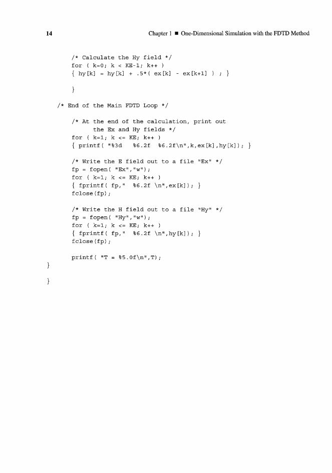
14 Chapter 1 • One-Dimensional Simulation with the FDTD Method
/* Calculate the Hy field */
for ( k=0; k < KE-1; k++ )
{ hy[k] = hy[k] + .5*( ex [k] - e x [ k + l ] ) ; }
}
/* End of the Main FDTD Loop */
/* At the end of the calculation, print out
the Ex and Hy fields */
for ( k=l; k <= KE; k++ )
{ printf( "%3d %6.2f %6.2f\n",k,ex[k],hy[k]); }
/* Write the E field out to a file "Ex" */
fp = fopen( "Ex","w");
for ( k=l; k <= KE; k++ )
{ fprintf( fp," %6.2f \n" /ex[k]) ; }
fclose(fp);
/* Write the H field out to a file "Hy" */
fp = fopen( "Hy","w");
for ( k=l; k <= KE; k+ + )
{ fprintf( fp," %6.2f \n",hy[k]) ; }
fclose(fp);
printf( "T = %5.0f\n",T);
}
}
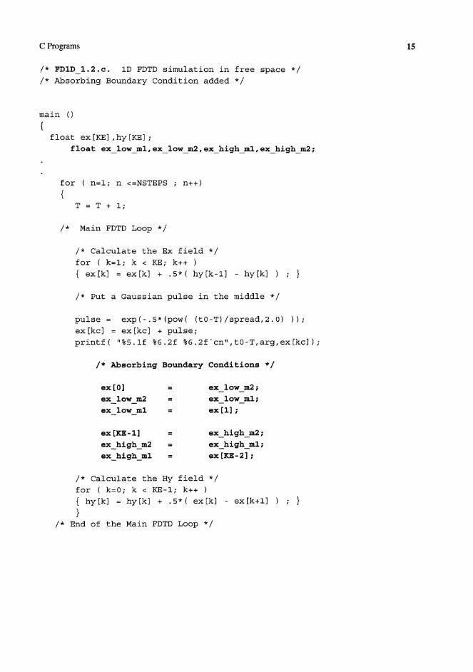
C Programs 15
/* FDlD__1.2.c. ID FDTD simulation in free space */
/* Absorbing Boundary Condition added */
main ()
{float ex[KE],hy[KE];
float ex_low_ml,ex_low_m2,ex_high_ml,ex_high_m2;
fo r ( n = l ; n <=NSTEPS ; n+ + )
{
T = T + 1 ;
/* Main FDTD Loop */
/* Calculate the Ex field */
for ( k=l; k < KE; k++ )
{ ex[k] = ex[k] + .5*( h y [ k - l ] - hy[k] ) ; }
/* Put a G a u s s i a n p u l s e i n t h e m i d d l e */
p u l s e = e x p ( - . 5 * ( p o w ( ( t O - T ) / s p r e a d , 2 . 0 ) ) ) ;
ex[kc] = ex[kc] + p u l s e ;p r i n t f ( "%5.1f %6.2f % 6 . 2 f ' e n " , t O - T , a r g , e x [ k c ] ) ;
/* Absorbing Boundary Conditions */
ex[0] = ex_!ow_m2;ex_low_m2 = ex_low_ml;ex_low_ml = ex[l];
ex[KE-1] = ex_high_m2;
ex_high_m2 = ex_high_ml;
exhighml = ex[KE-2];
/* Calculate the Hy field */
for ( k=0; k < KE-1; k++ ){ hyCk] = hy [k ] + . 5* ( ex [k] - e x [ k + l ] ) ; }
}/* End of the Main FDTD Loop */
T = T + 1;
/* Main FDTD Loop */
/* Calculate the Ex field */
for ( k=l; k < KE; k++ )
{ ex[k] = ex[k] + .5*( hy[k- l ] - hy[k] ) ; }
/* Put a G a u s s i a n p u l s e i n t h e m i d d l e */
p u l s e = e x p ( - . 5 * ( p o w ( ( t O - T ) / s p r e a d , 2 . 0 ) ) ) ;
ex[kc] = ex[kc] + p u l s e ;p r i n t f ( "%5.1f %6.2f %6.2f ' en" , tO-T,arg ,ex[kc] )
/* Absorbing Boundary Conditions */

16 Chapter 1 • One-Dimensional Simulation with the FDTD Method
/* FDlD_1.3.c. *//* Simulation of a pulse hitting a dielectric medium */
main ()
{float ex[KE],hy[KE];
int n,k,kc,ke,kstart,nsteps;
float ddx,dt,T,epsz,epsilon,sigma,eaf;
float cb[KE];
for ( k=l; k <= KE; k++ ) { /* Initialize to free space */
cb[k] = .5;
}printf( "Dielectric starts at --> " ) ;
scanf("%d", fckstart);
printf( "Epsilon --> " ) ;
scanf("%£", fcepsilon);
printf("%d %6.2f \n», k s t a r t , e p s i l o n ) ;
for ( k=kstart; k <= KE; k++ ) {
cb [k] = .5/epsilon;
}for ( k=l; k <= KE; k++ )
{ printf( "%2d %4.2f\n",k,cb[k]); }
/* Main part of the program */
while ( nsteps > 0 ) {
printf( "nsteps --> " ) ;
scanf("%d", &nsteps) ;
printf("%d \n", nsteps);
for ( n=l; n <=nsteps ; n++)
{T = T + 1;
/ * Calculate the Ex field * /
for ( k=0; k < KE; k++ )
{ ex[k] = ex[k] + cb [k] * ( hy[k-l] - hy [k] ) ; }
/* P u t a G a u s s i a n p u l s e a t t h e l o w e n d */
p u l s e = e x p ( - . 5 * ( p o w ( ( t O - T ) / s p r e a d , 2 . 0 ) ) ) ;
ex[5] = ex [5] + pulse;
p r i n t f ( " % 5 . 1 f % 6 . 2 f % 6 . 2 f \ n " , T , p u l s e , e x [ 5 ] ) ;

C Programs 17
/* FDlD_1.4.c. */
/* Simulation of a sinusoidal wave hitting a dielectric medium */
float ddx, dt;
float freq_in;
ddx = .01; /* Set the cell size to 1 cm */
dt = ddx/(2*3e8) /* Calculate the time step */
/* These parameters specify the input pulse */
printf( "Input freq (MHz)--> " ) ;
scanf("%f», fcfreqin);
freqin = freq_in*le6;
printf(" %8.0f \n», freq_±n)}
T = 0;
nsteps = 1;
/* Main part of the program */
while ( nsteps > 0 ) {
printf( "nsteps --> " ) ;
scanf("%d", &nsteps);
printf("%d \n", nsteps);
for ( n=l; n <=nsteps ; n++)
{T = T + 1;
/* Calculate the Ex field */
for ( k=0; k < KE; k++ )
{ ex[k] = ex[k] + cb [k] * ( hy[k-l] - hy[k] ) ; }
/* Put a sinusoidal source at cell 5 pO
pulse = sin(2*pi*freq_in*dt*T);
ex[5] = ex[5] + pulse;
p r i n t f ( "%5.1f %6.2f % 6 . 2 f \ n " , T # p u l s e f e x [ 5 ] ) ;

18 Chapter 1 • One-Dimensional Simulation with the FDTD Method
/*FDlD_1.5.c. ID FDTD s imula t ion of a lossy d i e l e c t r i c medium */
f l o a t ca[KE],cb[KE];
epsz = 8.85419e-12;
for ( k=l ; k <= KE; k++ ) { /* I n i t i a l i z e t o free space */caCk] = 1 . ;Cb[k] = . 5 ;
}p r i n t f ( " D i e l e c t r i c s t a r t s a t - - > " ) ;
s c a n f ( " % d M , fckstart);
p r i n t f ( " E p s i l o n - - > " ) ;
s c a n f ( " % f " # fcepsilon);
p r i n t f ( " C o n d u c t i v i t y --> " ) ;
s c a n f ( n % f " # & s i g m a ) ;
p r i n t f ( " % d %6.2f % 6 .2f \ n " , k s t a r t , e p s i l o n , s i g m a ) ;
eaf = dt*sigma/(2*epsz*epsilon);
printf(• %6.4f \n", eaf);
for ( k=kstart; k <= KE; k++ ) {
ca[k] = (1. - eaf)/(I + eaf) ;
cb[k] = .5/(epsilon*(1 + eaf) ) ;
}/* Main part of the program */
/* Calculate the Ex field */
for ( k=0; k < KE; k++ )
{ ex[k] = ca[k]*ex[k] + cb [k] * ( hy[k-l] - hy[k] ) ; }