on the unsteady loads induced by the bluff body wake of the ... · pdf fileon the unsteady...
TRANSCRIPT

IUTAM Symposium on Bluff Body Wakes and Vortex-Induced Vibrations22-25 June 2010: Capri Island-Italy
On the unsteady loads induced by the bluff body
wake of the Ariane 5 rocket.
Simon Marie∗ and Hadrien Lambare†
Centre National d’Etudes Spatiales - Rond Point de l’Espace, Courcouronnes 91023 EVRY CEDEX, FranceTel:+33 1 60 87 71 14 e-mail: [email protected]
1. Introduction
The rear-part of Ariane 5 rocket is the home of complex phenomena potentially involvingloads on the main nozzle. In particular, during transonic flight, space launchers after-bodiesare subjected to significant loads acting normally to the thrust. These dynamic loads arecaused by fluctuating pressure induced by a massively detached and turbulent flow. Thus,knowledge and control of side loads are of primary importance for the mechanical designof the launcher. This problem is well known in the literature and a lot of studies has beenexperimentally [3, 2, 6, 9] and numerically [8, 7] investigated on axisymmetric step flows.The goal of this study is to present some results for the real Ariane 5 configuration. Recently,some wind-tunnel tests have been made on a 1/60 scaled model of the real Ariane 5 rocketfor a deeper understanding of the phenomenon. This study presents a physical assessmentof the wind-tunnel tests made on three different configurations. The results are principallyobtained from unsteady kulites transducers. The role of geometrical parameters is highlightedand some discussions are made about the possibilities of reduction device.
2. Tests and Geometry
This work is based on the wind-tunnel tests made in NLR (Netherlands) [1, 4] in 2004and will include the 2010 tests in the complete presentations. The most critical part of thegeometry for side-loads considerations is located on the engine nozzle and the PTM (enginethermal protection). These parts have been instrumented with a total of 112 unsteady kulitesdistributed along 8 rings on a 1/60 scaled model of the real Ariane 5 rocket (Fig.1). For thisstudy, we will consider the tests made for a Mach number of 0.8 with a null incidence(α = β = 0). The fluctuating pressure is recorded during a period of 2.56 seconds sampledat 12800Hz.
A B
Fig 1. A Rear view of the geometry and principals axes of the model. B Position of sensors rings.
∗Post-Doctoral student at CNES†Expert engineer at CNES
1

S.Marie & H.Lambare/IUTAM symposium - Capri 2010 2
In order to study the influence of the geometry, three different configurations will beinvestigated. The description of these configurations is shown on Fig.2.
A B C
Fig 2. A Nominal configuration. B Configuration with a new LBS, C Configuration with a short cylindricalskirt.
These configurations are typical of three different flows inducing particular loads on thenozzle. The first configuration (Conf A) is the real model of the flying Ariane 5, the con-figuration with the new LBS (helium input for filling tanks at the ground) presents someminor geometrical modification inducing major consequences on the flow (Conf B) and theconfiguration with the skirt (Conf C) has been designed in order to reduce the loads.
3. Global approach
The first way to study the unsteady side-loads induced by the turbulent flow is to computedirectly the global load acting on the nozzle. The direct experimental measurement of thisquantity could be very difficult and demanding [3], therefore it could be useful to get thisinformation from the kulites transducers by integrating the pressure along the nozzle:
F(t) =∫ 2π
0
∫ L
0p(x, φ, t)r(x)ndx dφ ≡
Nc∑i=1
pi(t)dSi (1)
The validity of such an integration depends on the number of sensors involved in the exper-imental process [5]. A simple way to check the integration validity is to observe the decayof the azimuthal modes obtained by the spatial Fourier series decomposition of the powerspectral density (PSD) G(θ, f) of the fluctuating pressure along a ring:
G(θ, f) = a0 +∞∑
m=1
αm(f) cos mθ + βm(f) sinmθ (2)
A B
Fig 3. Amplitude of the azimuthal modes. A y-modes. B z-modes.

S.Marie & H.Lambare/IUTAM symposium - Capri 2010 3
The mechanical response of the structure is characterised by a pendulum mode around10Hz and an ovalisation mode around 25Hz. So the aerodynamic excitation should be evalu-
ated around the same frequency range. With these considerations, let define am =∫ f2
f1
αm(f)df
and bm =∫ f2
f1
βm(f)df with f1 = 5Hz and f2 = 40Hz. The evolution of these coefficients is
shown on Fig.3. The decrease of the mode amplitude allow us to use equation (1) to charac-terize the unsteady loads between 5 and 40Hz. The PSD of these loads is presented on Fig.4for the three configurations.
a. b.
Fig 4. a. PSD of y-load induced by the m = 1 mode. b. PSD of y-load induced by the m = 2 mode. Thesecurves are voluntarily set with arbitrary units
First, one can notice that the m = 1 mode excitation is characterized by a peak aroundStr = 0.2 (= 10Hz at Mach= 0.8) and a broad-band load around Str = 0.5. Moreover, them = 2 mode induces a broad-band load around Str = 0.5. This means that the aerodynamicexcitation fits the mechanical response of the structure (pendulum mode and ovalisationmode). This explains why the phenomenon is so important and could be damaging for thelauncher. Then, we observe that the new LBS (Conf B) induces some modifications in theunsteady load of the m = 1 mode around Str = 0.5. The local approach will allow us todeeper analyse these differences. Finally, we can note that the addition of a cylindrical skirt(Conf B) has a very positive effect on the phenomenon by reducing considerably the unsteadyloads on the nozzle.
4. Local approach
An other way to study the buffeting phenomenon is to look at the pressure PSD repartitionalong the geometry of the rear-body. Let Gp(θ, x, f) be the pressure PSD at the point [x, θ].The quantity f?(θ, x) such as:
Gp(θ, x, f?) = max[Gp(θ, x, f)] (3)
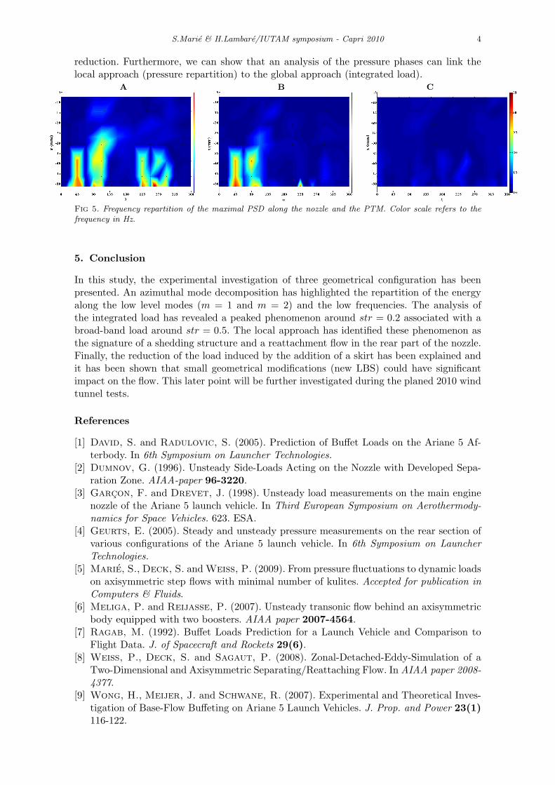
is a way to study the local frequency behaviour of the phenomenon. Fig.5 represents f?(x, θ)for the three configurations. The nominal configuration (Conf A) presents two particularareas (25◦ ≤ θ ≤ 100◦ and 220◦ ≤ θ ≤ 300◦) where the maximal PSD are characterized byfrequencies around 25Hz. This phenomenon could be interpreted as the consequences of thereattachment flow in these areas. Moreover, 10Hz frequencies (Str = 0.2 at Mach= 0.8) areobserved in the overall geometry and are the signature of a global shedding phenomenon.Then, it is shown that the new LBS has a local effect on the pressure by suppressing thereattachment of the flow in the area 220◦ ≤ θ ≤ 300◦. Finally, the addition of the cylindricalskirt suppresses the 25 Hz phenomenon and constitutes a good solution for unsteady load
S.Marie & H.Lambare/IUTAM symposium - Capri 2010 4
reduction. Furthermore, we can show that an analysis of the pressure phases can link thelocal approach (pressure repartition) to the global approach (integrated load).
A B C
Fig 5. Frequency repartition of the maximal PSD along the nozzle and the PTM. Color scale refers to thefrequency in Hz.
5. Conclusion
In this study, the experimental investigation of three geometrical configuration has beenpresented. An azimuthal mode decomposition has highlighted the repartition of the energyalong the low level modes (m = 1 and m = 2) and the low frequencies. The analysis ofthe integrated load has revealed a peaked phenomenon around str = 0.2 associated with abroad-band load around str = 0.5. The local approach has identified these phenomenon asthe signature of a shedding structure and a reattachment flow in the rear part of the nozzle.Finally, the reduction of the load induced by the addition of a skirt has been explained andit has been shown that small geometrical modifications (new LBS) could have significantimpact on the flow. This later point will be further investigated during the planed 2010 windtunnel tests.
References
[1] David, S. and Radulovic, S. (2005). Prediction of Buffet Loads on the Ariane 5 Af-terbody. In 6th Symposium on Launcher Technologies.
[2] Dumnov, G. (1996). Unsteady Side-Loads Acting on the Nozzle with Developed Sepa-ration Zone. AIAA-paper 96-3220.
[3] Garcon, F. and Drevet, J. (1998). Unsteady load measurements on the main enginenozzle of the Ariane 5 launch vehicle. In Third European Symposium on Aerothermody-namics for Space Vehicles. 623. ESA.
[4] Geurts, E. (2005). Steady and unsteady pressure measurements on the rear section ofvarious configurations of the Ariane 5 launch vehicle. In 6th Symposium on LauncherTechnologies.
[5] Marie, S., Deck, S. and Weiss, P. (2009). From pressure fluctuations to dynamic loadson axisymmetric step flows with minimal number of kulites. Accepted for publication inComputers & Fluids.
[6] Meliga, P. and Reijasse, P. (2007). Unsteady transonic flow behind an axisymmetricbody equipped with two boosters. AIAA paper 2007-4564.
[7] Ragab, M. (1992). Buffet Loads Prediction for a Launch Vehicle and Comparison toFlight Data. J. of Spacecraft and Rockets 29(6).
[8] Weiss, P., Deck, S. and Sagaut, P. (2008). Zonal-Detached-Eddy-Simulation of aTwo-Dimensional and Axisymmetric Separating/Reattaching Flow. In AIAA paper 2008-4377.
[9] Wong, H., Meijer, J. and Schwane, R. (2007). Experimental and Theoretical Inves-tigation of Base-Flow Buffeting on Ariane 5 Launch Vehicles. J. Prop. and Power 23(1)116-122.