on the theoretical relationship between flow stress and large natural strains in tensile tests on...
TRANSCRIPT
On the Theoretical Relationship between Flow Stress and Large Natural Strains in TensileTests on Steel CylindersAuthor(s): T. Y. ThomasSource: Proceedings of the National Academy of Sciences of the United States of America,Vol. 58, No. 1 (Jul. 15, 1967), pp. 11-18Published by: National Academy of SciencesStable URL: http://www.jstor.org/stable/58164 .
Accessed: 04/05/2014 16:17
Your use of the JSTOR archive indicates your acceptance of the Terms & Conditions of Use, available at .http://www.jstor.org/page/info/about/policies/terms.jsp
.JSTOR is a not-for-profit service that helps scholars, researchers, and students discover, use, and build upon a wide range ofcontent in a trusted digital archive. We use information technology and tools to increase productivity and facilitate new formsof scholarship. For more information about JSTOR, please contact [email protected].
.
National Academy of Sciences is collaborating with JSTOR to digitize, preserve and extend access toProceedings of the National Academy of Sciences of the United States of America.
http://www.jstor.org
This content downloaded from 62.122.78.41 on Sun, 4 May 2014 16:17:33 PMAll use subject to JSTOR Terms and Conditions

ON THE THEORETICAL RELATIONSHIP BET WEEN FLOW STIRESS AND LARGE NATURAL STRAINS IN TENSILE TESTS
ON STEEL CYLINDERS*
BY T. Y. THOMAS
INDIANA UNIVERSITY, BLOOMINGTON, INDIANA
Communicated May 22, 1967
(1) Introduction.-In his work on large plastic flow and fracture, Bridgman' was led to the following set of equations for the principal stresses in the minimum sec- tion of neck of a circular steel cylinder subjected to a tensile force in the direction of its axis and an imposed hydrostatic pressure p, namely,
oi -p + F log (a2 + 2aR - r2) (1)
0Y22 a 2 _ _ _ _ _ _ _ _r
2aR )' (2)
033 =--p + F + Flog(+ 2 .8 )' (3)
relative to the usual system of cylindrical coordinates xl,x2,x3 or r,G,z such that the z axis coincides with the axis of the cylinder. The remaining components a,j of the stress tensor are equal to zero over the minimum section of the neck. The quan- tity a is the radius of the minimum section of the neck and R is the radius of curva- ture, at the point P, of the necked profile, i.e., the curve of intersection MPN of a plane through the central axis and the outer boundary of the cylinder after necking
I N
aI
M FIG. 1.
(see Fig. 1). Finally, the quantity F in the equations (1), (2), and (3) is a constant which is called the flow stress by Bridgman. I have examined Bridgman's deriva- tion of the equations (1), (2), and (3) and I have frankly been impressed with the mathematical ingenuity he displayed and with the care he took to justify his pro- cedures with appropriate experimental evidence. There is little doubt in my mind
This content downloaded from 62.122.78.41 on Sun, 4 May 2014 16:17:33 PMAll use subject to JSTOR Terms and Conditions

12 ENGINEERING: T'. Y. THOMAS PROC. N. A. S.
but that these relations express the stress field over the minimum section of the neck to a high degree of approximation.
To determine the flow stress F one has merely to equate the integral of the stress component 033 over the minimum section of the neck to the applied load. This gives the relation
F (1 + 2 )log (1 +2 ) load (4)
in which it is observed that the hydrostatic pressure p does not appear due to the fact that the contribution of this pressure to the above integral is cancelled by its contribution to the actual load. After the measurements of a, R, and the load have been made, the flow stress F can be determined from the equation (4).
We shall be concerned in this paper with the theoretical relationship between the flow stress F and the natural strain defined as the logarithm of the ratio Ao/A where Ac. and A are the areas of the initial cross section of the cylinder and the minimum section of the neck, respectively. Table 1 gives the experimentally determined re- lationships between the flow stress and the natural strain for steels in the 11-0, 12-0, and 13-0 series; the corresponding graphs are shown in Figure 2. These graphs are linear to within experimental error and are typical of the relationship between flow stress and natural strain as found by tests on a large variety of steels. To deter- mine the possible effect of hydrostatic pressure on the stress-strain curves, Bridgman later conducted a number of tests on steels in the 9-7 and 9-8 series which he refers
TABLE 1 Hydrostatic pressure Natural strain, Flow stress
Spec. (psi) log(Ao/A) (psi) 11-0(-1 359,000 0.22 159,000 11-0-2 360,000 0.88 190,000 11-0-3 267,000 1.73 242,000 11-0-4 370,000 2.39 274,000 12-0-1 325,000 0.27 188,000 12-0-2 345,000 0.95 233,000 12-0-3 340,000 1.71 283,000 12-0-4 352,000 2.54 337,000 13-0-1 340,000 0.33 223,000 13-0-2 370,000 0.82 261,000 13-0-3 365,000 1.51 303,000 13-0-4 360,000 2.05 348,000
TABLE 2 Hydrostatic pressure Natural strain, Flow stress
Spec. (psi) log(Ao/A) (psi) 9-7-5 385,000 1.250 222,000 9-7-7 365,000 2.190 270,000 9-7-8 370,000 2.766 316,000 9-7-9 352,000 2.367 285,000 9-7-10 355,000 1.732 246,000 9-7-11 365,000 2.146 278,000 9-7-12 369,000 3.289 325,000 9-7-5 Atmos. 1.332 195,000 9-7-7 Atmos. 2.262 239,000 9-7-8 Atmos. 2.786 254,000 9-7-9 Atnios. 2.580 238,000 9-7-10 Atmos. 1.755 207,000 9-7-11 Atmos. 2.176 225,000 9-7-12 Atmos. 3.317 264,000
This content downloaded from 62.122.78.41 on Sun, 4 May 2014 16:17:33 PMAll use subject to JSTOR Terms and Conditions

VOL. 58, 1967 ENGINEERING: T. Y. THOMAS 13
to as tempered pearlite and tempered martensite, respectively. The behavior of these two steels was found to be qualitatively the same and we shall therefore list only the requisite data from the tests on tempered pearlite in Table 2. After the samples were tested at the large hydrostatic pressures shown in Table 2, they were again tested at atmospheric pressure. Figure 3, in which the dotted lines connect points obtained from the two above-mentioned tests on the same sample, shows the resulting graphs. Bridgman has interpreted these graphs as indicating that a hy-
350,000
(0
IL 3003000
w 250,000 11 ~ ~ ~ ~ ~~ ~~~~ 11- KRIRES
L l?o ? o / t t ~~~~~x I-0 SERIES 3 200,000 4??1l 9
LL 150__ __ __ __ __ __ __ __FIG. 2.
0 0.5 1.0 1.5 2.0 2.5 3.0
NATURAL STRAIN, LOG (AoIA)
t~~~~~~~~~~~~~~~ I
300,000
0~~~~~~~~~~~~~
Li 250,000
U) C,) w U)
200,000 _I IG.
0 LL
o PULLED AT 352,000 385,0000 or ~~~~~~X PULLED AT ATMOS. PRESSURE
0 0.5 1.0 1.5 2.0 2.5 3.0 F.5
NATURAL STRAIN, LOG (AoIA)
This content downloaded from 62.122.78.41 on Sun, 4 May 2014 16:17:33 PMAll use subject to JSTOR Terms and Conditions
14 ENGINEERING: T. Y. THOMAS PRoc. N. A. S.
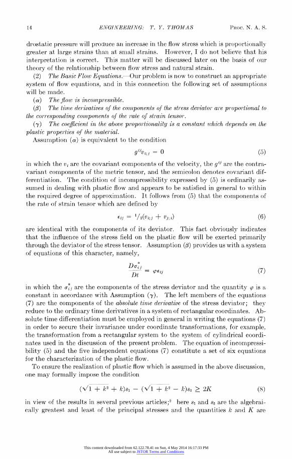
drostatic pressure will produce anl increase in the flow str ess which is proportionially greater at large strains thaii at snmall strainis. However, I do riot believe that his interpretation is correct. This matter will be discussed later oni the basis of our theory of the relationiship between flow stress anid natural straill.
(2) The Basic Flov Equations.-Our problem is now to construct anl appropriate system of flow equations, and in this connection the following set of assumptions will be made.
(a) The flow is incompressible. (A) The time derivatives of the components of the stress deviator are proportional to
the corresponding components of the rate of strain tensor. (,y) The coefficient in the above proportionality is a constant which depends on the
plastic properties of the material. Assumption (a) is equivalent to the condition
g1iv; - =O0 (5)
in which the vi are the covariant components of the velocity, the g1' are the contra- variant components of the metric tensor, and the semicoloni denotes covariant dif- ferentiation. The condition of incompressibility expressed by (5) is ordinarily as- sumed in dealing with plastic flow and appears to be satisfied in general to within the required degree of approximation. It follows from (5) that the components of the rate of strain tenisor which are defined by
Eij = 1/2(Vi;j + Vj;1i) (6)
are idenitical with the componients of its deviator. This fact obviously indicates that the influence of the stress field on the plastic flow will be exerted primarily through the deviator of the stress tensor. Assumption (3) provides us with a system of equations of this character, namely,
D:*>
Dtu*i (7)
in which the K* are the componients of the stress deviator anid the quantity f0 is a constant in accordance with Assumption ('y). The left members of the equationis (7) are the components of the absolute timne derivative of the stress deviator; they reduce to the ordiniary time derivatives in a system of rectanigular coordiniates. Ab- solute time differentiation must be employed in general in writing the equations (7) in order to secure their inivariance under coordinate transformations, for example, the transformation from a rectangular system to the system of cylindrical coordi- nates used in the discussion of the present problem. The equation of incompressi- bility (5) and the five independent equations (7) constitute a set of six equations for the characterization of the plastic flow.
To ensure the realization of plastic flow which is assumed in the above discussion, one may formally impose the condition
(V/I + k2 + k)si - (V1 + k2 - k)s3 > 2K (8)
i;n view of the results in several previous articles;2 here si and S3 are the algebrai- cdlly greatest and least of the principal stresses and the quantities k1 aind( K are
This content downloaded from 62.122.78.41 on Sun, 4 May 2014 16:17:33 PMAll use subject to JSTOR Terms and Conditions
VOL. 58, 1967 ENG[NEERING: 7'. Y. THOMAS 15
elastic inoduli. In this coimectioti it miiay be observed that (8) cannrlot reduce to ani equality since this would require the flow stress F to be constant during the necking process in contradiction to Bridgman's observations.
It will be seen from the derivations in the following section that the above flow equations lead to a very simple theoretical explanation of Bridgman's experimental results on flow stress and natural strain. But this is no more than one has a right to expect in view of the linear relationiship between these quantities as shown by the graphs in -Figs. 2 and 3. Indeed any theory of the relati.onship between flow stress and natural strain which is not of extreme simplicity should, in my opinion, be re- garded with considerable skepticism.
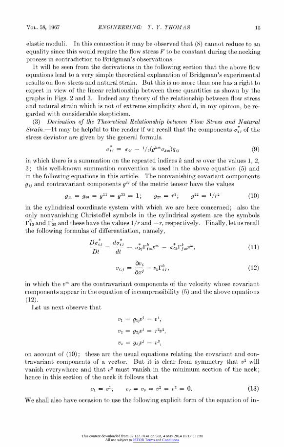
(3) Derivation of the Theoretical Relationship between Flow Stress and Natural Strain.-It may be helpful to the reader if we recall that the components * of the stress deviator are given by the general formula
(=ij - Gij - l/3(g kmk)gij (9)
in which there is a summationr on. the repeated indices k and mn over the values 1, 2, 3; this well-knowii summation convention is used in the above equation (5) and in. the following equations iri this article. The nonvanishing covariant conmponents gi and contravariant components gi1 of the metric tensor have the values
gll = g33 = g1= g33
= 1; g22= r2; g22 = I/r2 (10)
in the cylindrical coordinate system with which we are here concerned; also the only nonvanishing Christoffel symbols in the cylindrical system are the symbols P12 and r22and these havethe values 1/r and-i- respectively. Finally, letusrecall the following formulas of differentiation, namely,
Do-* d= o n - 74k1j?nVm, (11)
Dt dt '
bvj k Vi;j = b V -- vri, (12)
in which the vm are the contravariant components of the velocity whose covariant components appear in the equationt of incompressibility (5) and the above equations (12).
Let us next observe that
VI = gljvj = VI
V2 = g2jV j = r2v2
V3 = g3jV = V3v
on account of (10); these are the usual equations relating the covariant and con- travariant components of a vector. But it is clear from symmetry that v2 will vanish everywhere and that V3 must vanish in the minimum section of the neck; hence in this section of the neck it follows that
V1 == vI; V2 =V3 V2 = V3 = 0. (13)
We shall also have occasion to use the following explicit form of the equation of in-
This content downloaded from 62.122.78.41 on Sun, 4 May 2014 16:17:33 PMAll use subject to JSTOR Terms and Conditions
16 ENGINEERING: T. F. THOMAS PRoc. N. A. S.
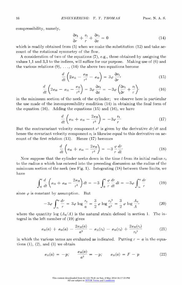
compressibility, namely,
bv1 vi 6V3 - + -+ v3 = 0 (14) ar r bz
which is readily obtained from (5) when we make the substitution (12) and take ac- count of the rotational. symmetry of the flow.
A consideration of two of the equations (7), e.g., those obtained by assigning the values 1,1 and 3,3 to the indices, will suffice for our purpose. Making use of (6) and the various relations (9), ..., (14) the above two equations become
d o-i - - - 0r33= 35 v (15) dt (15)
d (203 - - _ 22) = v3 = 3 v + v(16) dt r2 az a^r
in the minimum section of the neck of the cylinder; we observe here in particular the use made of the incompressibility condition (14) in obtaining the final form of the equation (16). Adding the equations (15) and (16), we have
d (20r22 v1 - (11+ 203
= 3 - (17) di r2/ r
But the contravariant velocity component vl is given by the derivative drl/dt and hence the covariant velocity component v1 is likewise equal to this derivative on ac- count of the first relation (13). Hence (17) becomes
d (20-22\ d - ( 11 + 033 ) = (18) dt )p2 / r dt Now suppose that the cylinder necks down in the time t from its initial radius ro
to the radius a which has entered into the preceding discussion as the radius of the minimum section of the neck (see Fi.g. 1). Integrating (18) between these linits, we have
('td 20q22 t ~odr a dr i(al + - 2 ) dt = -3 f - dt =-3f - (19)
.Jodt p2 r dt r
since so is constant by assumption. But
3 a dr, ro 3 l p02 3 Ao - 3 3p log -= - (lo 2 = s ~0Iog '1 (20)
Jro r ~~~~a 2 a 2 2 A
where the quantity log (Ao/A) is the natural strain defined in section 1. The in- tegral in the left member of (19) gives
0-n(a) + 0-33 (a) - 20r22(a) _ al1(0'0) _ 033(ro) + 20-22(ro) (21) a 2 - '(r -cr82o
in which the various term.s are evaluated as indicated. Putting r = a in the equa- tions (1), (2), and (3) we obtain
0-22(a) o-Tll(a) = ; 2 P; 0c33 (a) = F - p(22) a2
This content downloaded from 62.122.78.41 on Sun, 4 May 2014 16:17:33 PMAll use subject to JSTOR Terms and Conditions

VOL. 58, 196 PNVINEERINO: T. . THOMAg
from which the values of the first three terms in (21) are determined. At the start of the necking process the radius of the cylinder is ro and the stress field consists of a hydrostatic pressure p superimposed on a simple tension in the direction of the axis of the cylinder; hence the stress components ln(rD), 0722(rO), and o33(ro) are given by
o~~n(ro) = cr22(rO) (ro) p; r2 = p; o33(ro) _ r - P (23) rO
where r is the tensile strength of the cylinder. Making the substitutions (22) and (23) the expression (21) now reduces to F - . . Hence the equation (19) becomes
F =-.tensile strength + 3 sp log Ao (24) 2 A
when account is also taken of the relation (20). But from the result in our fore- going article2 we know that
tensile strength == gp + h
where the quantities g and h are givein in ternms of the elastic moduli k and K of the cylinder by the equations
g = 2k(\1 +d- 2-k); h = 2K(V1 + k2 - k).
It remains only to substitute the above expression for the tensile strength into the equation (24) to obtain the result that
3 A0 F gp + h ? 2 o - (25)
Equation (25) is the equation relating theflow stress F and the natural strain log (Ao/A) when the cylinder is pulled at the hydrostatic pressure p.
(4) Comparison between Theory and Experiinent.-The variation of tensile strength with hydrostatic pressure is small and will frequently be within the experi- mental error even for comparatively large pressures. It follows that there must also be a correspondingly small variation of flow stress with pressure as we see from the equation (24). The tensile strengths during the pullings of each of the steels in the 11-0, 12-0, and 13-0 series cani therefore be regarded as effectively constant and hence the experimental graphs must approximate straight lines as shown in Figure 2 in accordance with equation (24) or (25). The slope of each of these graphs will be given by 3 /2 where p is the plastic modulus of the samples in the series under consideration and the tensile strengths will be given by the F intercepts. Similar remarks apply to the upper graph in Figure 3 obtained from tests on virgin samples of tempered pearlite under the large hydrostatic pressures shown in Table 2.
The situation is somewhat different in the case of the lower graph in Figure 3. In fact the cylinders would have fractured well before the large strains were reached if one had attempted to carry out these tests using virgin material at atmospheric pressure. It is clear therefore that the mechanical properties of the samples were altered by the prestraining and hence the values of the moduli k, K, and p of the samples must also have been changed. Recognizing this fact and assigning the
This content downloaded from 62.122.78.41 on Sun, 4 May 2014 16:17:33 PMAll use subject to JSTOR Terms and Conditions

18 ENGINEERING: T. Y. THOMAS PRoc. N. A. S
appropriate values to these moduli, the theoretical graph obtained from the equa- tion (25) will be a straight line which will closely approximate the experimental graph as shown in Figure 3.
According to the equation (25) the flow stress F varies linearly both in the hydro- static pressure and the natural strain. Bridgman (ref. 1, p. 69) appears to have arrived at this result for strains in the intermediate range but he was not able to assert its validity under all conditions since he could not distinguish, solely on the basis of his observational data, between effects due to pressure arnd those due to changes in mechanical properties produced by prestraini.ng.
* Supported by the U. S. Army Research Office (Durham). 1 Bridgman, P. W., Studies in Large Plastic Flow and Fracture, Metallurgy and Metallurgical
Engirieering Series (New York: McGraw-Hill, 1952). 2 Thomas, T. Y., "Theoretical effect of large hydrostatic pressures on the tensile strength of
materials," these PROCEEDINGS, 57, 1195 (1967). Other references will be founl il this article.
This content downloaded from 62.122.78.41 on Sun, 4 May 2014 16:17:33 PMAll use subject to JSTOR Terms and Conditions