on the road to · 2019-06-17 · capacity a lot more capacity capacity booster ultra high capacity...
TRANSCRIPT

1 © Nokia 2017
On the road to
Use cases, technology & EMF standardization
Christophe Grangeat, 5G & SC Architecture Solutions, Senior specialist RF exposure & energy efficiencyAlistair Urie, Nokia Bell Labs, Advanced RAN architecture director2019-04-16

2 © Nokia 2017
On the road to 5G use cases
1 Video surveillance & analytics
2 Machine remote control
3 Assisted & autonomous vehicles
4 Cloud robotics & process automation
5 eHealth
6 Fixed Wireless Access
7 Immersive experience
8 Smart Stadium

© 2018 Nokia3
URLLC
eMBB
Th
rou
gh
pu
t
Latency
5Gphase1
5Gphase2
4.9G4.5G
Evolution of throughput, reliability and latencyRequirements driven by use cases
Immersive 360Throughput
UL: U-high / DL: high
Latency Reliability
50-100 ms Medium/high
eMTC with massive number of devicesThroughput
Low
Latency Reliability
10-100 ms U. High
FWA
Throughput
U-high
Latency Reliability
15-200 ms V. High
Mobile Tele-Operation (Vehicle and drone)
Throughput
Varies
Latency Reliability
1-10 ms Very high Industry robotics and automationThroughput
Varies
Latency Reliability
1-10 ms Very high
Public

© 2018 Nokia4
Flexible radio design, dynamic optimizationFor all use cases – also mission critical, high capacity, flexibility, new revenue streams
2
ExtremeMobile
Broadband
Massivemachine
communication
Critical machine
communication
Technology enablers for 5G New Radio (NR) interface and RAN
New spectrum options Massive capacity and throughput
300 MHz 3 GHz 30 GHz
10 GHz 100 GHz6 GHz
cmWave mmWaveLow bands High bands
1
Massive MIMO and Beam FormingMassive capacity , improved end-user experience, cell edge throughput
BF
1 Beam
B Ants
TX-1
TX-2
TX-B
Stream 1Multi-Beam BF
B Beams
Q Antennas o o
o
a1
a2
aQ
3
Multi-connectivity and aggregationEnd-user experience, extreme mobility, robustness and ultra reliability
t
Th
rou
gh
pu
t
# BSSpectrum Spectral efficiency
x x
x x
x x
4
Cloud nativeFlexible architecture
CU UP
DU
CU-CP CU-UP
RURU RURURU RU
DU
5
Public

© 2018 Nokia5
Spectrum: 5G bands from 300 MHz to 100 GHz
x =
300 MHz
3 GHz
30 GHz
10 GHz
100 GHz
10 cm
1m
1 cm
3 mm
Beam size
More beamforming
Small antennaNarrow beams
Very small Very narrow
beams
Medium antennaMedium beams
Large antennaWide beams
Bandwidth
More spectrum
Up to 400 MHz
Up to 2 GHz
Up to 100 MHz
Up to 20 MHz
Capacity
A lot more capacity
Capacity booster
Ultra high capacity booster
Coverage and high capacity
Coverage and new services
cm/mmwaves
24-40 GHz
mm waves
40-100 GHz
3-6 GHz
<3 GHz
x
Cell density
More cell sites
Dense small cell
Very dense small cell
Urban Macro and small cell
All Macro and urban small cell
Note: ITU-R is not considering bands between 6 and 24 GHz for IMT2020
600-900 MHz
3.5 GHz
26/28 GHz
39 GHz
Firstbands
1. Spectrum
Public

© 2018 Nokia6 Public
3 key spectrum ranges start to emerge Different spectrum for different use cases
Low band< 1 GHz
Mid-band3 – 6 GHz
mmWaves> 24 GHz
Spectrum range
• 600 MHz (US)• 700 MHz• 900 MHz
• 3.4-3.6 GHz (B42)• 3.6-3.8 GHz (B43)• 4.5-4.9 GHz (JPN)
• 26 GHz (EUR)• 28 GHz (KOR, US)• 39 GHz (US)
Bands
• Deep indoor• ~ 10 km
• Same grid as LTE1800
• ~1 km
• Hot spots• Line of sight• 100 m
Coverage
~100 Mbps
~1 Gbps
~10 Gbps
PeakData rates
FDD2x10 MHz
TDD<100 MHz
TDD<1 GHz
Bandwidth
• Deep indoor coverage for sensors and IoT (mMTC)
• TMO US started to promote also MBB
• 5G eMBB coverage on LTE grid• Major commercial 5G launches are
expected in this spectrum range (JPN, KRN, CHN, EUR)
• Extreme data rates for e.g. VR in local areas like stadiums
• Used in US due to lack of 3-6 GHz• Used also in KOR Olympics trial
Use Cases
Da
ta r
ate
Ce
ll ra
ng
e1. Spectrum

© 2018 Nokia7
Around the world, there is a pattern of band allocationGlobal snapshot of 5G spectrum
5GHz4GHz3GHz<1GHz 24-28GHz 37-40GHz 64-71GHz
600MHz (2x35MHz) 3.5GHz (150MHz) 27.5-28.35GHz
700MHz 3.4–3.8GHz 24.5-27.5GHz
3.4–3.8GHz 26GHz, 28GHz
3.4–3.7GHz 26GHz, 28GHz
3.46 –3.8GHz 26GHz
3.6–3.8GHz
3.3 –3.6GHz 4.8 –5GHz 24.5-27.5GHz 37.5-42.5GHz
3.4–3.7GHz 26.5-29.5GHz
4.4–4.9GHz 27.5-29.5GHz
3.4–3.7GHz 28GHz 39GHz
3.6–4.2GHz
64-71GHz37-37.6GHz37.6-40GHz
5.9–6.4GHz
5.9–7.1GHz
600MHz (2x35MHz) 3.5GHz (150MHz) 27.5-28.35GHz 64-71GHz5.9–7.1GHz
2.5GHz (LTE B41)
37-37.6GHz37.6-40GHz
Licensed
Unlicensed/shared
Existing band
New 5G band
1. Spectrum
Public

© 2018 Nokia8
3GPP background – New Radio (NR) functionalityStand-Alone (SA) and Non-Standalone (NSA)
Feature Standalone (SA) Non-standalone (NSA)
Master carrier NR LTE and eLTE NR
Secondary carrier - NR eLTE
Core choice 5G core (5GC) 4G EPC or 5G core (5GC) 5G core (5GC)
Operator perspective Simple, high performance overlay Leveraging existing 4G deployments
Vendor perspective Independent RAN product Requires tight interworking with LTE
End user experience Peak bitrate set by NRDedicated Low Latency transport
Peak bitrate is sum of LTE and NRLatency impacted if routed via LTE master
NR (5G)LTE/eLTE (4G)NR (5G) eLTE (4G)NR (5G)
2. Radio design
Public

© 2018 Nokia9
“New Radio” (NR) numerology building on LTEFlexible radio design
Radio LTE New Radio (NR)
Bands <4 GHz < 3GHz 2-6 GHz > 6 GHz
Multiple access CP-OFDM / SC-OFDM
CP-OFDM / CP-OFDM (+ SC-OFDM)
Duplex FDD, TDD FDD TDD
Sub-carrier (kHz) 15 15, 30, 60 15, 30, 60 60, 120
Carrier BW (MHz) 1.4 .. 20 5 .. 40 5 .. 100 50 .. 400
Carrier loading 90% 90 .. 97% 90 .. 98% 95%
Slot per 10ms frame 10 10-20 10-80 80
Channel codes Turbo LDPC (plus Polar for PBCH and PxCCH channels)
NR radio interface: a more flexible OFDM than LTE
2. Radio design
Public

© 2018 Nokia10
Lean carrier also offers base station energy savingsFlexible radio design
• Cell specific reference signal transmission 4x every millisecond
• Synchronization every 5 ms• Broadcast every 10 ms
LTE
NR
• No cell specific reference signals
• Synchronization every 20 ms• Broadcast every 20 ms• Adjustable slot >20 ms
planned
20 ms
Very limited capability for base station energy savings due to continuous transmission of cell reference signals
5G enables advanced base station energy savings
= Primary synchronization
= Secondary synchronization
= Broadcast channel
= LTE cell reference signals
2. Radio design
Public

© 2018 Nokia11
Example: loading within 100 MHz spectrum allocation5G Enhances Spectral Utilization
18 MHz 18 MHz 18 MHz 18 MHz 18 MHz
100 MHz
100 MHz
LTE 5x20 MHz
NR 100 MHz
More efficient than multicarrier LTE
• LTE limited to 100 PRB per 20 MHz carrier (i.e. 90% of carrier bandwidth)
• NR supports wider carriers and larger transmit BW (up to 98% of carrier BW)
• No unnecessary guard bands between narrow carriers
Up to 98 MHz
2. Radio design
Public

© 2018 Nokia12
70%
75%
80%
85%
90%
95%
100%
1,4 3 5 10 15 20 25 30 40 50 60 80 90 100 200 400
Carrier bandwidth [MHz]
Spectrum utilizationLTE
NR-FR1 15
NR-FR1 30
NR-FR1 60
NR-FR2 60
NR-FR2 120
5G Spectrum Utilization up to 98%
5G spectrum utilization is up to 98% of carrier bandwidth 40-100 MHz
LTE utilization maximum 90%
Offers up to +8%improvement in max spectrum utilization
97%98%
LTE 90%
2. Radio design
95%
Public
© 2018 Nokia13 Public
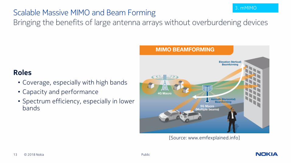
Bringing the benefits of large antenna arrays without overburdening devicesScalable Massive MIMO and Beam Forming
Roles
• Coverage, especially with high bands
• Capacity and performance
• Spectrum efficiency, especially in lower bands
3. mMIMO
[Source: www.emfexplained.info]

© 2018 Nokia14
MIMO and beam forming dimensionsMassive MIMO
MIMO layers
• Sets total number of parallel data paths in sector for SU- and MU-MIMO
• Determines overall sector capacity limits
Transmitter / Receiver (TRx)
• Sets number of parallel beams during same TTI
Base station Antenna elements (AE)
• Structured in rows, columns and polarisation (e.g. 8 columns x 8 rows x 2 xpol= 128 elements)
• With digital BF, sets net beam gain
UE Receivers (Rx)
• Sets maximum number of layers towards a given UE for SU-MIMO. 4 Rx minimum for NR
MIMO(Layer mapping and precoding)
Digital Beam Forming
… # Layers
… # TRx
# BS Antenna elementsRF beam forming
# Rx
MIMO
MIMO radio channel
# UE Antenna elements
Public
3. mMIMO

© 2018 Nokia15
Performance estimationMassive MIMO
0
2
4
6
8
10
2x2 4x4 8x8 16TRX 32TRX 64TRX
b/s
/Hz
/ce
ll
NR downlink spectrum efficiency
2 layers
4 layers
8 layers
16 layers
LTE 2x2
x5
Public
3. mMIMO

© 2018 Nokia16
Re-using LTE techniques to go beyond handoverMulti-connectivity and aggregation
Dual-connectivity between layers
Combining macro and small cells
Carrier aggregation
Combining carriers intra and inter site
Dual-connectivity between radios
Combining across radio technologies
Coordinated Multi-Point (CoMP)
Combining between cell sites
NR (band Y)
NR (band X) NR (band X)
NR (band Y)
NR
NR
NR
LTE
Wi-Fi
4. Multi-connectivity
Public

© 2018 Nokia17 Public
Accelerating 5G NR3GPP standardization timeline
Enhanced mobile broadband
Full 5G Future X architecture
Ultra reliable low latency communications
Massive machine-type communications
20212017 2019 2020 20222018
Industry agrees on 5G NR acceleration
Early drop (NSA)
Release 15 (SA)
Release 16
Early drop deployment
Phase 1 deployment
Phase 2 deployment
Release 15• 5G Non-Standalone (NSA, option 3) and 5G core (5GC) stage 2 completed Dec. 17, with ASN.1 completed March 18 and key corrections
agreed in June, Sept and Dec. 18 • 5G Standalone (SA, option 2), eLTE (option 5), 5GC stage 3 completed June 18 with ASN.1 completed Sept. 18, key cor. agreed in Dec. 18• “Late Drop” for 5GC NSA solutions (options 4&7) and NR-NR dualco now due March 19 with ASN.1 in June 2019
Release 16 studies completed in 2018, rel. 16 completion due March 2020 with ASN.1 due June 2020

© 2018 Nokia18
5G equipment examples
Public
Small cells
Macros
Backhaul
Devices
Gateway box
Macros including
beamforming

19 © Nokia 2017
Frequency range: 110 MHz to 100 GHz
Single standard including methods for • Product compliance
• Product installation compliance
• In-situ RF exposure assessment
Simplified rules• Low power exclusion for product compliance
• Product installation classes
• In-situ RF exposure
Uncertainty• Target value (best ind. practice) & maximum value
Annex B (normative): • All details of evaluation methods (measurements &
calculations)
Annex F (informative): • Technologies
• Introduction of compliance based on actual max power
RF-EMF exposure assessment methods One worldwide applicable international standard – IEC 62232:2017
Public

20 © Nokia 2017
One practical implementation guide – IEC TR 62669:2019 Uses cases and introduction of compliance based on actual service
Public
§ Base station type Evaluation type Evaluation method
6 Small cell (indoor local area BS) Product compliance (6.1) SAR measurements (B.3.2)
7 Small cell (outdoor medium range BS) Product compliance (6.1) SAR measurement (B.3.2)
8 Small cell Product installation compliance (6.2) Field strength computations (B.4)
9 Small cell In-situ RF exposure assessment (6.3) Field strength measurements (B.3.1)
10 Street cell Product compliance (6.1)SAR (B.3.2) and field strength (B.3.1) measurements
11 Macro site In-situ RF exposure assessment (6.3) Field strength measurements (B.3.1)
12 Macro site (inspection with drone) In-situ RF exposure assessment (6.3) Field strength measurements (B.3.1)
13 All types of BSCompliance using the actual maximum transmitted power or EIRP
Field strength measurements (B.3), computations (B.4) & actual max (B.5)
14 Macro (massive MIMO) Product compliance (6.1) Field strength computations (B.4)
15 Macro and small cell (massive MIMO) Product installation compliance (6.2) Field strength computations (B.4)
16 Small cell (massive MIMO)Product installation compliance (6.2) and in-situ RF exposure assessment (6.3)
Field strength measurements (B.3) and computations (B.4)
17Wireless link using parabolic dish antenna
Product compliance (6.1) Field strength computations (F.11)

21 © Nokia 2017
Measurement campaign A
• Measurements according to IEC 62232:2017 + uplink/downlink statistics
• 9 outdoor sites with medium range small cells in urban furniture
Measurement campaign B
• Measurements according to IEC 62232:2017
• 295 measurement points on 98 sites
• South Africa (80), Amsterdam (16) & Turin (2)
• Indoor (47), Outdoor 2 m to 4 m (30) and Outdoor > 4 m (21)
Example: small cells in-situ measurement campaigns (from IEC TR 62669:2019 – Clause 9)
Public

22 © Nokia 2017
→ Confirmed by in-situ measurement campaigns presented in Clause 9
Example: small cells simplified installation classes(from IEC TR 62669:2019 – Clause 8)
Public

23 © Nokia 2017
Towards compliance based on actual serviceExample of time-averaged EIRP of a 4G cell
Public
Actual max
Actual max

24 © Nokia 2017
→ The actual transmitted power (time-avg) does not exceed a threshold (= actual maximum threshold)
→ Power reduction factors (actual max threshold/configured max) vary from 5 to 7 dB
What do we know about new technologies (beamforming) ?Time & space variation of RF transmitted power with 5G massive MIMO
Public
Source:IEC TR 62669:2019, Nokia Bell Labs,modelling
Actual max
(95th)
6.0dB
Source:IEC TR 62669:2019, Ericsson,modelling
Actual max
(95th)
Actual max
(95th)
7.2 dB
5.0 dB
Source:IEC TR 62669:2019, Vodafone,measurements
Actual max
5.2 dB

25 © Nokia 2017
Modelling of the novel compliance approach (from IEC TR 62669:2019)EIRP is a key parameter of the base station influencing RF exposure level
Public
Base station installation parameters(fixed configuration)
PTXM: maximum configured transmitted power
FTDC: scaling factor representing the technology
GMLB: gain in the main lobe of the antenna
Parameterrepresenting the
variation of transmitted power due to the traffic
Parameterrepresenting the
variation the antenna gain due to beam
steering

26 © Nokia 2017
General principle for RF compliance based on actual max power: [from IEC TR 62669:2019 §13.1.2]
• The real time-averaged transmitted power by BSs during service, called actual transmitted power, is generally below the time-averaged maximum transmitted power.
• Therefore, as a conservative approach, the actual maximum transmitted power can be used to determine the RF compliance boundary provided that the operator is implementing tools ensuring this threshold is not exceeded over time during service.
• These tools can be based on BS counters and features developed by manufacturers to monitor and control the RF transmitted power or EIRP and other relevant characteristics of the BS.
• This applies to all types of BS, whether they are using fixed beams or steerable beams like with mMIMO.
Implementation of the novel compliance approach (from IEC TR 62669:2019)Principles
Public

27 © Nokia 2017
Implementation of the novel compliance approach (from IEC TR 62669:2019)Example with current radio technologies (non beamforming)
Public
EMF compliance boundaryassessment
andsite declaration/approval
EIRP actual max threshold
Not allowed Monitoring & control toolsProof points
available upon request
Po
we
r re
d.
fact
or
Power reduction
factor

28 © Nokia 2017
Implementation of the novel compliance approach (from IEC TR 62669:2019)Flow chart applicable to a BS site sector or site sector sub-division
Public
b) 1) Evaluate the RF compliance boundary using the actual maximum transmitted power or EIRP threshold
b) Before putting into service
b) 2) Configure the BS and implements tools ensuring that the time-averaged transmitted power or EIRP does not exceed the time-averaged actual maximum transmitted power or EIRP threshold over time
a) 1) use the maximum value of the measured time-averaged transmitted power or EIRP from measurements taken on a single operational BS
a) 2) use a percentile derived from measurements taken on a larger number of representative BS sites
a) Specify the actual max threshold
a) 3) otherwise use a percentile derived from computation models on BS sites with similar config. & env.
c) During service
c) 1) Record periodically the CDF of the time-averaged transmitted power or EIRP
c) 2) Record BS actual maximum transmitted power or EIRP threshold CDF in the assessment reports
d) 3)In case of threshold change (config. or perf.)

29 © Nokia 2017
IEC 62232 next edition development with TC106 MT3Same structure with enhanced content
Public
Domain Technical topic Clauses & sub-clauses
New Actual max approach Process Process in §6.1, 6.2 and 6.3
Actual max approach Monitoring & control specification Methods in new §8.4
Beamforming (including mMIMO) Product compliance 6.1
Actual max & beamforming In-situ measurements (including extrapolation) 6.3
Power density assessment Include power density measurements (63195) & computations (62704-5)
6.1, 8.2 and 8.3
Frequency range & dish antennas Extension of higher frequency & inclusion dish antenna formulas All, 6.1 and Annex B
Meas. using drones In-situ meas. process 6.3 and 8.2
Maint.
Technology annex Update (NR) & simplify Annex F and main body
Table 2 Update and more didactic 6.2
Multiple sources Include missing formulas & align with others (e.g. 62311) New 8.5 and references in 6.1, 6.2 and 6.3
Uncertainty Clarification from remaining NC comts 9 and Annex E
Consistency with ICNIRP rev Review & update if/where necessary 5, 8 and Annex B

30 © Nokia 2017
Implementation of the novel compliance approachFrom IEC TR 62669:2019 guidelines to the next edition of IEC 62232 standard
Public
Global RF exposure assessment standardIEC 62232:2017
Jul’17
Implementation guideIEC TR 62669:2019
→ novel approach (rationale and principles for RF compliance based on actual max service)
→ adopted in ITU-T K.Sup16
Apr’19 Dec’19
Introduction of the novel compliance
approach in IEC 62232
→ 1st consolidated draft(committee draft)
Dec’20
IEC 62232 next edition
→ technical freeze (committee draft for vote )
National authorities update RF compliance regulations for early 5G deployments
IEC 62232 next edition
publication target 2021

31 © Nokia 2017
Thank you!