on the reliability of the numerical models for oil
TRANSCRIPT

ON THE RELIABILITY OF THE NUMERICAL MODELS FOR OIL
INDUSTRY APPLICATIONS.
Rita G. Toscano and Eduardo N. Dvorkin
SIM&TEC, Av. Pueyrredón 2130 5°A, C1119ACR Buenos Aires, Argentina, www.simytec.com
Keywords: reliability, collapse, validation, verification.
Abstract. Establishing manufacturing tolerances for steel pipes to be used in the oil industry, such as
amplitude of the out-of-roundness, specially its second mode in Fourier decomposition, eccentricity,
residual stresses, etc., is an involved issue that should balance production cost with expected
performance.
Finite element simulations are nowadays a standard industrial tool for exploring the effect of those
tolerances on the structural behavior as well as on the performance of tubular goods, and to study the
technological windows (the locus in the space of the process control variables that defines a given
process set-up) of the pipes production process that will render products within the expected
tolerances.
Hence, it is of the utmost importance that sound computational techniques are used and that the model
results are validated using experimental results.
Regarding the modeling of steel pipes collapse and post-collapse behavior, in this paper we propose
some guidelines for the development of finite element models that simulate collapse tests.
Some of the aspects that we discuss are: applicability of 2D models, shell elements for the 3D models,
nonlinearities to include in the models, material modeling, residual stresses modeling, boundary
conditions for simulating different pressure tests, code verification and results validation.
Regarding the link between production process and manufacturing tolerances we briefly review some
results that we obtained for the case of the UOE process and threaded connections for OCTG (oil
country tubular goods).
Mecánica Computacional Vol XXIX, págs. 7949-7964 (artículo completo)Eduardo Dvorkin, Marcela Goldschmit, Mario Storti (Eds.)
Buenos Aires, Argentina, 15-18 Noviembre 2010
Copyright © 2010 Asociación Argentina de Mecánica Computacional http://www.amcaonline.org.ar

1 INTRODUCTION
Establishing manufacturing tolerances for steel pipes to be used in pipelines, such as
amplitude of the out-of-roundness specially its second mode in Fourier decomposition,
eccentricity, residual stresses, etc. is an involved issue that should balance production cost
with expected performance.
Finite element models are nowadays a standard tool for exploring the effect of those
tolerances on the collapse and collapse propagation pressure of tubular goods and to study the
technological windows (the locus in the space of the process control variables that defines a
given process set-up) of the pipes production process that will render products within the
expected tolerances.
Since technological decisions, with high influence on the ecological impact of industrial
facilities and pipeline installations, on labor conditions and on revenues, are reached based on
the results provided by numerical models, it is evident that these models have to be highly
reliable. Therefore, it is of the utmost importance that sound computational techniques are
used and that the model results are subjected to experimental validation.
In this paper we propose some guidelines for the development of finite element models that
simulate collapse tests.
Some of the aspects that we discuss are,
The applicability of 2D and 3D models.
Shell elements for the 3D models.
Long vs. short models.
Nonlinearities to include in the models.
The use of follower loads.
Material modeling.
Modeling of residual stresses.
Code verification and results validation.
Regarding the link between production process and manufacturing tolerances, we briefly
review some results that we obtained for the case of the UOE process and threaded connections
for OCTG (oil country tubular goods).
2 MODEL DEFINITIONS
In this section we discuss the decisions that we have to make for defining the finite
element models that are going to be used for investigating the effect of manufacturing
tolerances on the collapse and post-collapse behavior of steel pipes.
2.1 The applicability of 2D and 3D models
Material properties, residual stresses and pipe dimensions like eccentricity, out-of
roundness, thickness, etc. vary along the length of a specific pipe.
When the collapse behavior of a specific pipe is investigated, then a 3D model that
incorporates a detailed geometrical and material description needs to be developed.
However, we may also need to perform parametric studies to investigate the effect of
manufacturing tolerances on the collapse and collapse propagation pressures; in these cases
R. TOSCANO, E. DVORKIN7950
Copyright © 2010 Asociación Argentina de Mecánica Computacional http://www.amcaonline.org.ar

we consider an infinite pipe with uniform properties along its length and we use a 2D plane
strain model built using continuum elements or 3D short shell models, if we need to include
bending in the analysis.
2.2 Two dimensional finite element model of very long pipes
To study the effect of ovality, eccentricity and residual stresses on the collapse external
pressure, we developed a model using 2D continuum elements QMITC (Dvorkin and Vassolo,
1989; E.N.Dvorkin, Assanelli and Toscano, 1996), with the mesh shown in Fig.1. Half of the
pipe is modeled due to symmetry. To assess on the quality of this mesh we analyzed the plane
strain collapse of an infinite pipe and we compared our numerical results with the analytical
ones obtained using the formulas developed in (Timoshenko and Gere, 1961).
From the results in Table 1 we concluded that the proposed 2D mesh of QMITC elements
is accurate enough to represent the collapse of very long specimens.
OD (outer pipe diameter) 245.42 mm
Wall thickness 12.61 mm
Ovality 0.18%
Yield stress 890 MPa
Theoretical pcr (collapse pressure) 64.36 MPa
Dcr
ltheoreticacr
p
p
2
0.992
Table 1: Qualification of 2D continuum elements model
In this work, the ovality (Ov ) and eccentricity ( ) are defined as,
averageOD
ODODOv minmax (1)
averagethickness
thicknessthickness minmax (2)
Figure 1. 2D continuum mesh
Mecánica Computacional Vol XXIX, págs. 7949-7964 (2010) 7951
Copyright © 2010 Asociación Argentina de Mecánica Computacional http://www.amcaonline.org.ar
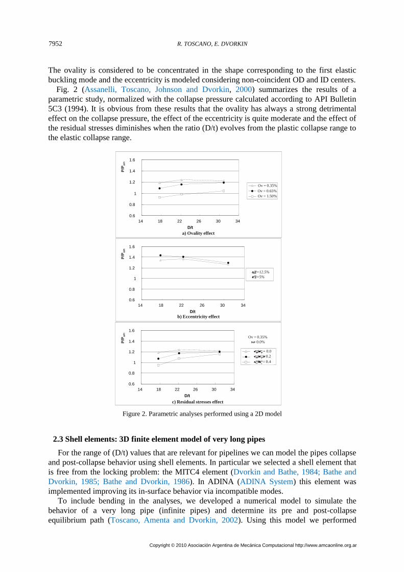
The ovality is considered to be concentrated in the shape corresponding to the first elastic
buckling mode and the eccentricity is modeled considering non-coincident OD and ID centers.
Fig. 2 (Assanelli, Toscano, Johnson and Dvorkin, 2000) summarizes the results of a
parametric study, normalized with the collapse pressure calculated according to API Bulletin
5C3 (1994). It is obvious from these results that the ovality has always a strong detrimental
effect on the collapse pressure, the effect of the eccentricity is quite moderate and the effect of
the residual stresses diminishes when the ratio (D/t) evolves from the plastic collapse range to
the elastic collapse range.
0.6
0.8
1
1.2
1.4
1.6
14 18 22 26 30 34
D/t
Ov=0.35%
Ov=0.65%
Ov=1.50%
0.6
0.8
1
1.2
1.4
1.6
14 18 22 26 30 34
D/t
0.6
0.8
1
1.2
1.4
1.6
14 18 22 26 30 34
D/t
sR/sy= 0.4
R y/ = 0.2
R y/ = 0.4
R y/ = 0.0
P/P
AP
IP
/PA
PI
P/P
AP
I
Ov = 0.35%
= 0.0%
Ov = 0.35%
Ov = 1.50%
Ov = 0.65%
/2=12.5%
/2=5%
a) Ovality effect
c) Residual stresses effect
b) Eccentricity effect
Figure 2. Parametric analyses performed using a 2D model
2.3 Shell elements: 3D finite element model of very long pipes
For the range of (D/t) values that are relevant for pipelines we can model the pipes collapse
and post-collapse behavior using shell elements. In particular we selected a shell element that
is free from the locking problem: the MITC4 element (Dvorkin and Bathe, 1984; Bathe and
Dvorkin, 1985; Bathe and Dvorkin, 1986). In ADINA (ADINA System) this element was
implemented improving its in-surface behavior via incompatible modes.
To include bending in the analyses, we developed a numerical model to simulate the
behavior of a very long pipe (infinite pipes) and determine its pre and post-collapse
equilibrium path (Toscano, Amenta and Dvorkin, 2002). Using this model we performed
R. TOSCANO, E. DVORKIN7952
Copyright © 2010 Asociación Argentina de Mecánica Computacional http://www.amcaonline.org.ar

parametric studies in order to investigate the significance of the different geometrical
imperfections and of the residual stresses on the collapse and collapse propagation pressures.
Fig. 3 shows the mesh we used.
Regarding the boundary conditions, in these models we used constraint equations to
impose the planarity of the transversal sections.
For the cases with external pressure plus bending we first imposed the bending and then the
external pressure keeping constant the imposed curvature.
n
n
n
z
y x
Figure 3.3D finite element model of very long pipes
Figures 4a and 4b show the curve External pressure vs. ovality and the evolution of the
pipe cross section of a pipe under external pressure plus bending.
0
500
1000
1500
2000
2500
0.0% 50.0% 100.0% 150.0% 200.0%
Ovality [%]
Ex
tern
al
pre
ss
ure
[m
H2
O]
A
C
B
Initial ovality=0.3%
Figure 4a. External pressure vs. ovality
Mecánica Computacional Vol XXIX, págs. 7949-7964 (2010) 7953
Copyright © 2010 Asociación Argentina de Mecánica Computacional http://www.amcaonline.org.ar

Figure 4b.Initial, intermediate and final shapes of the pipe cross section. Equivalent logarithmic strains.
In Fig. 5 we measured the applied curvature with the radius "R" and with the maximum
bending strain (as a reference we indicated the radius of a typical reel used to lay marine
pipelines). Even though the pipes initial ovality has a strong influence on the pipes critical
collapse pressure when no bending is applied, the effect of the initial ovality on the pipes
critical collapse pressure diminishes when the imposed curvature is increased. When a
perfectly round tube is bent the cross section is ovalized ("Brazier effect"), when the bending
increases, the Brazier-ovality grows and therefore the pipes initial ovality becomes less
important as compared with this bending-induced ovality.
0.0
500.0
1000.0
1500.0
2000.0
2500.0
3000.0
3500.0
4000.0
4500.0
5000.0
5500.0
0.00% 1.00% 2.00% 3.00% 4.00% 5.00% 6.00% 7.00%
Strain [%]
Ex
tern
al c
olla
ps
e p
ress
ure
[m
H2
O]
10.95
R [m]
5.48 3.65 2.74 2.19 1.8354.77
-- Initial pipe ovality: 0.30%
-- Initial pipe ovality: 1.00%
Pc DNV (ov=0.50%- min DNV)
Pc DNV (ov=1.00%)
Radius of typical Reel
8.50
Figure 5. Ovality effect on the collapse pressure. 8 5/8" x 12.7 mm X-60 pipe
Finally, to compare the predictions using 2D elements and shell elements we considered
the case described in Table I. We compared the plane strain result obtained using the QMITC
element with the shell model result developed imposing zero axial displacements. The
difference between both models was only 1.2%.
2.4 Shell elements: 3D finite element model of finite pipes
The 3D finite element models of finite pipes were developed to overcome the limitations of
the simpler models described previously.
It is important to take into account that when the sample is long enough (L/D>10) the end
R. TOSCANO, E. DVORKIN7954
Copyright © 2010 Asociación Argentina de Mecánica Computacional http://www.amcaonline.org.ar

conditions have only a very small influence on the collapse pressure (Fowler, Klementich and
Chappell, 1983).
Following with the example described in Table 1, we compared the results obtained using
the two different shell models,
Short model with no axial displacements (shell under plane strain conditions)
(L/D=10) model with the ends restrained to remain on a plane via constraint equations
(welded end cups)
The results summarized in Table 2 indicate the equivalence of both models. For cases with
(L/D<10) we may expect the end conditions to play a more significant role.
Short model
under plane strain
conditions
980.0_ PSshellcr
ltheoreticacr
p
p
Long model;
(L/D)=10 978.0
_ longshellcr
ltheoreticacr
p
p
Table 2: long shell model compared with plane strain shell model
2.5 Nonlinearities
In this subsection we analyze the nonlinearities that we must include in our finite element
models to be able to predict the collapse of steel pipes under external pressure and to track
their post-collapse behavior (Palmer and Martin, 1975).
Since we need to predict collapse, we have to use a geometrically nonlinear analysis
considering large displacements/rotations, that is to say we have to fulfill the equilibrium
equations in the deformed configuration (Bathe, 1996). However, as seen in Fig. 6, used for
the validation of the model that predicts the post-collapse behavior of a pipe with collapse
arrestors, even if very high strains are developed at localized points, the general behavior of
the post-collapse response can be determined without including in the analyses finite strain
models.
Figure 6. Infinitesimal or finite strains (flipping mode)
Mecánica Computacional Vol XXIX, págs. 7949-7964 (2010) 7955
Copyright © 2010 Asociación Argentina de Mecánica Computacional http://www.amcaonline.org.ar
In the range of (D/t) values that are within our scope, the collapse is an elastic-plastic
collapse, that is to say plasticity is developed before and after collapse; hence the material
nonlinearity has to be included in the analysis.
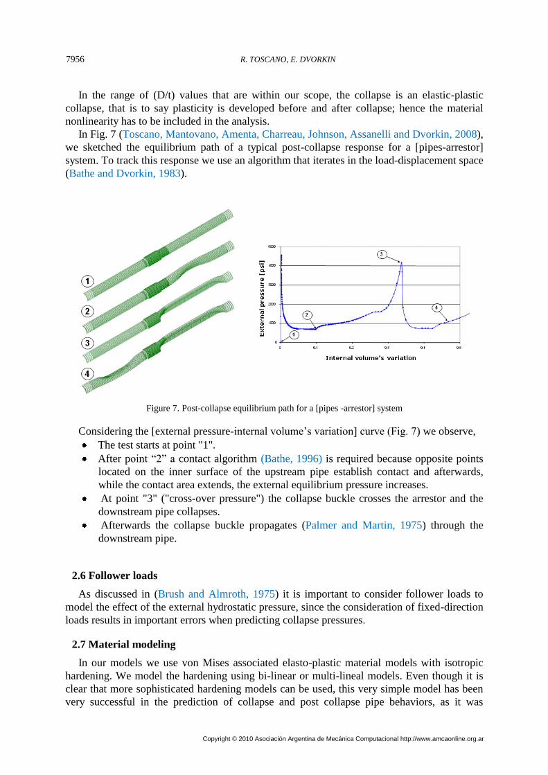
In Fig. 7 (Toscano, Mantovano, Amenta, Charreau, Johnson, Assanelli and Dvorkin, 2008),
we sketched the equilibrium path of a typical post-collapse response for a [pipes-arrestor]
system. To track this response we use an algorithm that iterates in the load-displacement space
(Bathe and Dvorkin, 1983).
Figure 7. Post-collapse equilibrium path for a [pipes -arrestor] system
Considering the [external pressure-internal volume’s variation] curve (Fig. 7) we observe,
The test starts at point "1".
After point “2” a contact algorithm (Bathe, 1996) is required because opposite points
located on the inner surface of the upstream pipe establish contact and afterwards,
while the contact area extends, the external equilibrium pressure increases.
At point "3" ("cross-over pressure") the collapse buckle crosses the arrestor and the
downstream pipe collapses.
Afterwards the collapse buckle propagates (Palmer and Martin, 1975) through the
downstream pipe.
2.6 Follower loads
As discussed in (Brush and Almroth, 1975) it is important to consider follower loads to
model the effect of the external hydrostatic pressure, since the consideration of fixed-direction
loads results in important errors when predicting collapse pressures.
2.7 Material modeling
In our models we use von Mises associated elasto-plastic material models with isotropic
hardening. We model the hardening using bi-linear or multi-lineal models. Even though it is
clear that more sophisticated hardening models can be used, this very simple model has been
very successful in the prediction of collapse and post collapse pipe behaviors, as it was
R. TOSCANO, E. DVORKIN7956
Copyright © 2010 Asociación Argentina de Mecánica Computacional http://www.amcaonline.org.ar

demonstrated in Refs. (Assanelli, Toscano, Johnson and Dvorkin, 2000; Toscano, Amenta and
Dvorkin, 2002; Toscano, Mantovano, Amenta, Charreau, Johnson, Assanelli and Dvorkin,
2008; Toscano, Timms, Dvorkin and DeGeer, 2003; Toscano, Gonzalez and Dvorkin, 2003)
(see Fig. 6, 8 and the verification section, Figs. 10-12).
Figure 8. FEM vs. experimental results
2.8 Modeling of residual stresses
In most of our analyses we considered a linear residual stresses distribution across the pipe
wall thickness. In (Assanelli, Toscano, Johnson and Dvorkin, 2000) we checked the modeling
of the residual stresses distribution by modeling a slit ring test using the ADINA “element
birth and death” feature. In the slit-ring tests the samples are cut and slit open by machining.
To determine the residual stresses, the measured openings are post-processed according to
the following formulas,
)1(4 22R
EtaR
(long sample) (3)
24 R
EtaR (short sample) (4)
Where,
a: opening of the slit ring sample
t: average thickness
E: Young’s modulus
R: mean pipe radious
Mecánica Computacional Vol XXIX, págs. 7949-7964 (2010) 7957
Copyright © 2010 Asociación Argentina de Mecánica Computacional http://www.amcaonline.org.ar

The meshes before and after slitting are shown in Fig. 9, while Table 2 summarizes the
obtained results.
Figure 9. Residual stresses measurement: meshes before and after slitting (slit ring tests)
Sample length aFEA / aanalytical
25 mm 1.02
3 OD 0.99
Table 2. Residual stresses: numerical vs. analytical results
3 CODE VERIFICATION AND MODEL VALIDATION
In the verification process we have to prove that we are solving the equations right, and
therefore this is a mathematical step (Roache, 1998). In this step we have to show that our
numerical scheme is convergent and stable.
It is important to notice that the verification process is not only related to a numerical
procedure but also to its actual implementation in software (either commercial software or an
in-house one) (Roache, 1998).
In the validation process we have to prove that we are solving the right equations, and
therefore it is an engineering step (Roache, 1998).
We do validate neither a formulation nor software: we validate the usage of verified
software when used by a design analyst in the simulation of a given process. We have to
validate the complete procedure.
In (Toscano, Timms, Dvorkin and DeGeer, 2003; Toscano, Gonzalez and Dvorkin, 2003)
we present the results of a full-scale test program and finite element analyses performed on
seamless steel line pipe samples under external pressure only and external pressure plus
bending. These laboratory tests were carried out in order to obtain experimental results to be
used in the validation of the numerical models. In those references we described the
experimental program, compared the experimental vs. numerical results and evaluated the
sensitivity of the numerical results to small variations in the model data.
Regarding arrestors, to validate our numerical results on buckling arresting and cross-over
R. TOSCANO, E. DVORKIN7958
Copyright © 2010 Asociación Argentina de Mecánica Computacional http://www.amcaonline.org.ar

mechanisms, we performed a series of laboratory tests on medium-size carbon steel pipes
(Toscano, Mantovano, Amenta, Charreau, Johnson, Assanelli and Dvorkin, 2008).
3.1 Finite element model of buckle arrestors for deepwater linepipes
In (Toscano, Mantovano, Amenta, Charreau, Johnson, Assanelli and Dvorkin, 2008) we
developed a complete validation of the collapse and post-collapse analyses of pipes with
collapse arrestors. We can observe the flattening (Figs. 10 and 11) and flipping modes (Fig 6
and 12) described in the literature (Park and Kyriakides, 1997).
The comparison between the experimentally and numerically determined, pressure vs.
volume variation curves and post-collapse shapes indicate that the models developed using the
above discussed methodology were very successful in simulating the collapse and post-
collapse behavior of steel pipes.
Figure 10. FEM vs. experimental results for a flattening cross-over
Tested sample
Finite element mesh
Groove
Figure 11. Experimentally observed and FEM predicted shapes of collapsed pipes after a flattening cross-over
Mecánica Computacional Vol XXIX, págs. 7949-7964 (2010) 7959
Copyright © 2010 Asociación Argentina de Mecánica Computacional http://www.amcaonline.org.ar
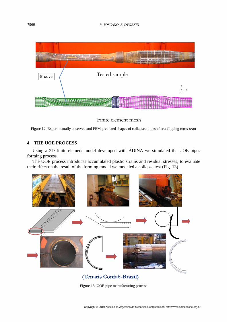
Tested sample
Finite element mesh
Groove
Figure 12. Experimentally observed and FEM predicted shapes of collapsed pipes after a flipping cross-over
4 THE UOE PROCESS
Using a 2D finite element model developed with ADINA we simulated the UOE pipes
forming process.
The UOE process introduces accumulated plastic strains and residual stresses; to evaluate
their effect on the result of the forming model we modeled a collapse test (Fig. 13).
(Tenaris Confab-Brazil)
Figure 13. UOE pipe manufacturing process
R. TOSCANO, E. DVORKIN7960
Copyright © 2010 Asociación Argentina de Mecánica Computacional http://www.amcaonline.org.ar

Details of these models were provided in (Toscano, Raffo, Fritz, Silva, Hines and Timms,
2008).
As an example, Figure 14 presents the evolution, along the UOE process, of the
accumulated plastic strains of a 16” x 0.5” WT X60 pipe.
Figure 14. Accumulated effective plastic strains evolution [%]
Fort the same pipe, the results of a parametric analysis performed with the composed
model are shown in Fig. 15, where TC is total compression in the “O” press.
Figure 15. Results of the forming+collapse models.
It is clear that, controlling the compression rate in the “O” press and the expansion rate, the
collapse behavior can be optimized.
5 THREADED CONNECTIONS
We analyzed the structural and functional behavior of threaded connections using bi-
dimensional models and QMITC elements. In previous publications (Assanelli and Dvorkin,
1998; Assanelli and Dvorkin, 1993) we showed the validation and verification of those
numerical models.
Mecánica Computacional Vol XXIX, págs. 7949-7964 (2010) 7961
Copyright © 2010 Asociación Argentina de Mecánica Computacional http://www.amcaonline.org.ar

It is well known that if during the connection make-up, too much dope is used either in the
seal area or in the thread area, the extra dope gets trapped and develops a high pressure that
can damage the connection. Of course, different connection designs have more or less
capability for avoiding the dope trapping.
A connection similar to the one shown in Fig. 16 was made-up with extra dope; the dope
pressure values were measured during the make-up.
In Fig. 17 we compare the strains measured experimentally with the numerical results
obtained with and without the inclusion of the dope pressure; it is obvious that when the dope
pressure distribution determined in the full-scale test was included in the finite element model,
the numerical results showed a very good agreement with the experimental ones.
Figure 16. Threaded&coupled connection. 2D mesh.
FEA vs. Strain Gages (with dope pressure)
1.28 Turns
-5000
-4000
-3000
-2000
-1000
0
1000
2000
0 20 40 60 80 100 120 140 160
Axial distance from box center [mm]
Ho
op
str
ain
s [
u.s
train
s]
SG pin
SG box
FEA box (without D.P.)
FEA pin (without D.P.)
FEA box (with D.P.)
FEA pin (with D.P.)
Figure 17. Strains comparison considering dope pressure in an
over-doped connection
R. TOSCANO, E. DVORKIN7962
Copyright © 2010 Asociación Argentina de Mecánica Computacional http://www.amcaonline.org.ar

6 CONCLUSIONS
A methodology for using the finite element method as a robust engineering tool for
analyzing the effect of steel pipes manufacturing tolerances on their collapse and post-collapse
behavior was discussed.
It was shown that 2D models can only be used for performing general parametric analyses
and not for predicting the collapse and post-collapse behavior of a specific pipe.
For including bending and material/geometrical variations along the pipes length, 3D
models should be used. We showed that using the MITC4 shell element for developing these
3D models is a successful procedure.
Even though we have to introduce geometrical nonlinearities for the simulation of the
collapse and post-collapse behavior, the use of finite strain models is only necessary if the
local strains/stresses are sought, but their consideration can be avoided if only the equilibrium
path is sought.
The use of very simple bilinear elasto-plastic models provided an excellent agreement
between the numerical and experimental results.
Regarding the link between production process and manufacturing tolerances, we present
some results obtained with the UOE process model as well as the threaded connections model.
The modeling of the UOE process produced specific indications for optimizing the pipes
collapse pressure working on the process parameters, while the results obtained including the
dope pressure as a load in the connections model was a definitive demonstration of the high
importance of designing the connections with the objective of avoiding the dope entrapment.
REFERENCES
1. Dvorkin, E.N. and Vassolo, S.I., "A quadrilateral 2-D finite element based on mixed
interpolation of tensorial components", Engng. Comput., 6, pp. 217-224, 1989.
2. Dvorkin, E.N., Assanelli, A.P. and Toscano, R.G., “Performance of the QMITC element
in 2D elasto-plastic analyses”, Computers & Structures, 58, pp.1099-1129, 1996.
3. Timoshenko, S.P. and Gere, J.M., Theory of Elastic Stability, Mc Graw Hill, 1961.
4. Assanelli, A.P., Toscano, R.G., Johnson, D.H. and Dvorkin, E.N., “Experimental /
numerical analysis of the collapse behavior of steel pipes”, Engng. Computations, 17,
pp.459-486, 2000.
5. Dvorkin, E.N. and Bathe, K.J., “A continuum mechanics based four-node shell element
for general nonlinear analysis”, Engng. Computations, 1, pp. 77-88, 1984.
6. Bathe, K.J. and Dvorkin, E.N., “A four-node plate bending element based on Mindlin /
Reissner plate theory and a mixed interpolation”, Int. J. Numerical Methods in Engng.,
Vol. 21, pp. 367-383, 1985.
7. Bathe, K.J. and Dvorkin, E.N., “A formulation of general shell elements - the use of
mixed interpolation of tensorial components”, Int. J. Numerical Methods in Engng., 22,
pp.697-722, 1986.
8. The ADINA System, www.adina.com
9. Toscano R.G., Amenta P.M. and Dvorkin E.N., "Enhancement of the Collapse
Resistance of Tubular Products for Deep-Water pipeline Applications", IBC'S
OFFSHORE PIPELINE TECHNOLOGY, Conference documentation, Amsterdam, 2002.
10. Fowler, J.R., Klementich, E.F. and Chappell, J.F., “Analysis and testing of factors
affecting collapse performance of casing”, ASME . Energy Res. Tech., 105, pp. 574-579,
1983.
Mecánica Computacional Vol XXIX, págs. 7949-7964 (2010) 7963
Copyright © 2010 Asociación Argentina de Mecánica Computacional http://www.amcaonline.org.ar

11. Palmer, A.C. and Martin, J.H., “Buckle propagation in submarine pipelines”, Nature,
254, pp. 46-48, 1975.
12. Bathe, K.J., Finite Element Procedures, Prentice Hall, Upper Saddle River N.J., 1996.
13. Toscano, R.G., Mantovano, L.O., Amenta, P.M., Charreau, R.F., Johnson, D. H.,
Assanelli, A. P. and Dvorkin, E.N., “Collapse arrestors for deepwater pipelines. Cross-
over mechanisms”, Computers & Structures, 86, pp. 728-743, 2008.
14. Bathe, K.J. and Dvorkin, E.N., “On the automatic solution of nonlinear finite element
equations”, Computers & Structures, 17, pp. 871-879, 1983.
15. Brush, D.O. and Almroth, B.O., Buckling of Bars, Plates and Shells, MacGraw-Hill,
1975.
16. Toscano, R.G., Timms, C., Dvorkin, E.N. and DeGeer, D., "Determination of the
collapse and propagation pressure of ultra-deepwater pipelines", Proceedings OMAE
2003 - 22nd. International Conference on Offshore Mechanics and Artic Engineering,
2003.
17. Toscano, R.G., Gonzalez, M. and Dvorkin, E.N., "Validation of a finite element model
that simulates the behavior of steel pipes under external pressure", The Journal of
Pipeline Integrity, 2, pp.74-84, 2003.
18. Roache, P.J., Verification and Validation in Computational Science and Engineering,
Hermosa Publishers, 1998.
19. Park T.D. and Kyriakides S., "On the performance of Integral Buckle Arrestors for
Offshore Pipelines", International Journal of Mechanical Sciences, Vol.39 pp.643-669,
1997.
20. Toscano, R.G., Raffo, J., Fritz, M., Silva, R., Hines, J. and Timms, C., "Modeling the
UOE Pipe Manufacturing Process", Proceedings OMAE 2008 –OMAE2008-57605,
27nd. International Conference on Offshore Mechanics and Artic Engineering, Estoril,
Portugal, 2008.
21. Assanelli, A.P. and Dvorkin, E.N., “Selection of an adequate element formulation for
modeling OCTG connections”, Computational Mechanics – New trends and
applications, (Ed. S.Idelsohn et al), CIMNE, 1998.
22. Assanelli, A.P. and Dvorkin, E.N., "Finite element models of OCTG threaded
connections", Computers & Structures, Vol.47, pp.725-734, 1993.
R. TOSCANO, E. DVORKIN7964
Copyright © 2010 Asociación Argentina de Mecánica Computacional http://www.amcaonline.org.ar