on the jets, kinks, and spheromaks formed by a planar
TRANSCRIPT

On the jets, kinks, and spheromaks formed by a planar magnetizedcoaxial gun
S. C. Hsua! and P. M. Bellanb!
California Institute of Technology, Pasadena, California 91125
sReceived 26 May 2004; accepted 4 November 2004; published online 4 February 2005d
Measurements of the various plasma configurations produced by a planar magnetized coaxial gunprovide insight into the magnetic topology evolution resulting from magnetic helicity injection.Important features of the experiments are a very simple coaxial gun design so that all observedgeometrical complexity is due to the intrinsic physical dynamics rather than the source shape anduse of a fast multiple-frame digital camera which provides direct imaging of topologically complexshapes and dynamics. Three key experimental findings were obtained:s1d formation of an axialcollimated jetfHsu and Bellan, Mon. Not. R. Astron. Soc.334, 257 s2002dg that is consistent witha magnetohydrodynamic description of astrophysical jets,s2d identification of the kink instabilitywhen this jet satisfies the Kruskal–Shafranov limit, ands3d the nonlinear properties of the kinkinstability providing a conversion of toroidal to poloidal flux as required for spheromak formationby a coaxial magnetized sourcefHsu and Bellan, Phys. Rev. Lett.90, 215002 s2003dg. Aninterpretation is proposed for how then=1 central column instability provides flux amplificationduring spheromak formation and sustainment, and it is shown that jet collimation can occur withinone rotation of the background poloidal field. ©2005 American Institute of Physics.fDOI: 10.1063/1.1850921g
I. INTRODUCTION
There has long been a mutually beneficial exchange ofideas between laboratory plasma physics and plasma astro-physics. An example is the proposal by Lundquist1 that cos-mical magnetic fields are force-free,2 satisfying¹3B=lB.Woltjer showed3 that these force-free states are intimatelyrelated to the concept of magnetic helicity conservation andthat the force-free state results from a variational principle inwhich the magnetic energy of a system is minimized subjectto the constraint of constant magnetic helicity, which is ameasure of magnetic flux twist and linkage.4 This idea wasthen used to explain the spontaneous generation of reversedmagnetic fields in the reversed field pinch5 and the tendencyof coaxial gun produced plasmas to reach the spheromakstate.6 Although Taylor relaxation,7 as this process is nowknown, is not a complete and rigorous theory, it was verysuccessful, indicating that the same fundamental physicalprinciples govern both laboratory and astrophysical plasmas.The Taylor argument showed that the end result of complexdynamics is a relatively simplerelaxedstate, but the argu-ment sidesteps the issue of characterizing the detailed dy-namical processes leading to this state. This paper describesrecent experiments providing insights into the detailed dy-namical processes of magnetic helicity injection and plasmarelaxation. In particular, the experiments shed light on thenonaxisymmetric dynamics of spheromak formation, a sub-ject with a long history beginning with the work of Alfvén8
and Lindberg.9 These experiments also show how magnetic
helicity injection can lead to the formation and collimation ofmagnetically driven jets in astrophysics.10–12
An important feature of this experiment is the use of thesimplest possible setup for allowing studies of the details andthree-dimensionals3Dd dynamics of magnetic helicity injec-tion and spheromak formation. Key results includes1d obser-vation of distinct plasma regimes depending on the param-eterlgun sratio of peak gun current to fluxd, similar to thosepreviously found13 using a conventional cylindrical coaxialgun, s2d formation and axial expansion of a central plasmacolumn from merging of plasma-filled poloidal flux tubes14
in a manner consistent with magnetohydrodynamicsMHDdmodels of magnetically driven astrophysical jets,12,15–17 s3dclear identification of a kink instability of this central columnand a kink onset threshold that is quantitatively consistentwith the Kruskal–Shafranov limit for an ideal MHDkink,14,18 and s4d identification of the nonlinear limit of thekink instability as a poloidal flux amplification mechanismleading to spheromak formation.18
This paper is organized as follows. Section II describesthe experimental setup. Section III presents the experimentalresults. Section IV provides a detailed discussion of the re-sults in the context of both spheromak formation and astro-physical jets. A summary is given in Sec. V.
II. EXPERIMENTAL SETUP
In order to facilitate interpretation of results, the coaxialgun design was made to be as geometrically simple as pos-sible: a disk surrounded by a coplanar annulusfFig. 1sadg anda bias magnetic field coil located just behind the diskfnotvisible in Fig. 1sadg. This experimental setup provided theadditional advantage that the entire plasma formation regionis in plain view so that all steps of the topological evolution
adPresent address: Los Alamos National Laboratory, Los Alamos, NM87545. Electronic mail: [email protected]
bdElectronic mail: [email protected]
PHYSICS OF PLASMAS12, 032103s2005d
1070-664X/2005/12~3!/032103/12/$22.50 © 2005 American Institute of Physics12, 032103-1
Downloaded 14 Dec 2005 to 131.215.225.9. Redistribution subject to AIP license or copyright, see http://pop.aip.org/pop/copyright.jsp
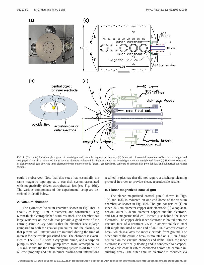
could be observed. Note that this setup has essentially thesame magnetic topology as a star-disk system associatedwith magnetically driven astrophysical jetsfsee Fig. 1sbdg.The various components of the experimental setup are de-scribed in detail below.
A. Vacuum chamber
The cylindrical vacuum chamber, shown in Fig. 1scd, isabout 2 m long, 1.4 m in diameter, and constructed using6 mm thick electropolished stainless steel. The chamber haslarge windows on the side that provide a good view of theentire plasma. A key point is that the chamber size is largecompared to both the coaxial gun source and the plasma, sothat plasma-wall interactions are minimal during the time ofinterest for the results presented here. The chamber is evacu-ated to 1.5310−7 T with a cryogenic pump, and a sorptionpump is used for initial pump-down from atmosphere to100 mT so that the the entire pumping system is oil-free. Theoil-free property and the minimal plasma-wall interactions
resulted in plasmas that did not require a discharge cleaningprotocol in order to provide clean, reproducible results.
B. Planar magnetized coaxial gun
The planar magnetized coaxial gun,19 shown in Figs.1sad and 1sdd, is mounted on one end dome of the vacuumchamber, as shown in Fig. 1scd. The gun consists ofs1d aninner 20.3 cm diameter copper disk electrode,s2d a coplanar,coaxial outer 50.8 cm diameter copper annulus electrode,and s3d a magnetic field coil located just behind the innerelectrode. The copper disk inner electrode is bolted onto thevacuum face of a reentrant 7.5 in. diameter stainless steelhalf nipple mounted on one end of an 8 in. diameter ceramicbreak which insulates the inner electrode from ground. Theother end of the ceramic break is mounted on a 10 in. flangecentered on the vacuum chamber end-dome. Thus, the innerelectrode is electrically floating and is connected to a capaci-tor bank via coaxial cables connected across the ceramic in-sulating break. The outer annulus electrode is mounted via
FIG. 1. sColord. sad End-view photograph of coaxial gun and rotatable magnetic probe array.sbd Schematic of essential ingredients of both a coaxial gun andastrophysical star-disk system.scd Large vacuum chamber with multiple diagnostic ports and coaxial gun mounted on right end dome.sdd Side-view schematicof planar coaxial gun, showing inner electrodesblued, outer electrodesgreend, gas feed lines, contours of constant bias poloidal flux, and cylindrical coordinatesystem.
032103-2 S. C. Hsu and P. M. Bellan Phys. Plasmas 12, 032103 ~2005!
Downloaded 14 Dec 2005 to 131.215.225.9. Redistribution subject to AIP license or copyright, see http://pop.aip.org/pop/copyright.jsp

copper brackets directly to the inner surface of the vacuumchamber end dome and therefore is electrically tied to cham-ber ground. A 6 mm vacuum gap separates the disk and outerannulus. The experiments are characterized using the cylin-drical coordinate system shown in Fig. 1sdd; the f andsR-Zd directions will be referred to as toroidal and poloidal,respectively. The disk and annulus each have eight 6 mmdiameter gas injection holes spaced equally inf. The gasinjection holes on the disk and annulus are atR=4.8 and17.8 cm, respectively. Details of gas injection are given inSec. II D. The external bias magnetic field coil is located justbehind the central disk but, because of the reentrant geom-etry, is at atmosphere. The coil consists of 110 turns of No.11 insulated square magnetic wire wound on a phenolic forms13.0 cm inner and 18.4 cm outer diametersd and has an in-ductance of 2.3 mH and resistance of 0.39V. Contours ofconstant poloidal fluxc generated by the coil are shown inFig. 1sdd.
C. Power systems
The coaxial gun is powered by an ignitron-switched120 mF capacitor bank rated up to 14 kV. Eight 2 m longBelden YK-198 low inductance coaxial cables in parallelcarry power from the capacitor bank to the gun electrodes.Routine operation at bank voltages of 5 kV yields peakplasma currents Igun<80 kA and gun voltagesVgun
<2.5 kV safter breakdownd, or peak gun power on the orderof 200 MW. TypicalIgun andVgun traces are shown in Fig. 2.
The external magnetic field coil is powered by a 1.4 mF,450 V capacitor bank. The half period of the current trace forthe external coil is 10 ms and is effectively constant on the10 ms time scale of the experiment. The bias poloidal mag-netic flux cgun sintercepting the inner gun electroded createdby the external coil is typically 1–2 mWb.
D. Gas injection
Fast gas puffs are required in these experiments becauselocal gas pressures on the order of 100 mT are required forbreakdown. A slow or steady gas fill is intolerable becausethe entire vacuum chamber would rise to 100 mT whichwould result in a weakly ionized cold plasma and also anoverloading of the cryopump. Fast gas valves provide a tran-sient, highly localized cloud of high pressure gas in front of
the gun electrodes. The gas valves utilize a pulsed current ina thin pancake coil to induce image currents in an adjacentaluminum disk20 but also employ a plenum for measured,reproducible gas output. The disk is thus repelled from thecoil, creating a transient opening for gas flow from the ple-num into the vacuum chamber. Restoring force on the disk isprovided by a combination of the high pressure gas in the gaslines and a metal spring. Calibrations indicate that each pulseinjects 1020–1021 hydrogen molecules, depending on the ap-plied voltage. Optimum timing of gas valve firing is deter-mined empirically by adjusting the valve firing time to mini-mize the delay between capacitor bank trigger and gasbreakdownstypically a few microsecondsd. One valve isused for the eight inner electrode gas injection holes, and twovalves are used for the eight outer electrode holes. Typicalgas valve firing voltage is 600 V, with all three valves inject-ing on the order of 1021 hydrogen molecules. It was foundthat the amount of gas injected per pulse slowly increasedthroughout the day21 due to heating in the electrolyticcapacitors22 powering the gas valve. A new power supplyusing metal film polypropylene capacitors has been con-structed recently to eliminate this problem.22
E. Diagnostics
The images presented in this paper were taken withmultiple-frame charge-coupled devicesCCDd cameras. Mostof the images were taken with a Cooke Co. HSFC-PROsFig.3d. The specifications for this camera are as follows: 4 or 8frames per shot, 128031024 pixels per frame,12 bits per pixel, a 10 ns minimum exposure time, and aminimum interframe time of 5 nss250 nsd in 4 s8d shotmode. Other images were taken with a DRS Hadland Imacon200 sFig. 8d, which has 8 or 16 frames per shot, 12003980 pixels per frame, 10 bits per pixel, a minimum 10 nsexposure time, and a minimum of 5 nss250 nsd interframetime in 8 s16d shot mode. The camera is placed on a tripodand positioned in front of the right-most vacuum chamberwindow shown in Fig. 1scd.
Magnetic field data are taken with a radial array of smallpickup coils mounted on a stainless steel shaft, which can bescanned inZ and rotated inf. The array contains twentygroups of three coils arranged so that all three components ofB are measured fromR=0 to R=40 cm with 2 cm resolu-tion. The coils are commercial chip inductorssCoil Craft1008CS-472XGBBd and have calibrated turns3area NA<1.3 cm2. The coils are placed into precision-machinedslots of a long thin strip of Delrin, which in turn is slid downa thin-wall stainless steel tube covered by an alumina tube toprevent metal contact with the plasmafsee Fig. 1sadg. Thealumina has an outer diameter of 8.4 mm. The frequencyresponse, limited by the skin effect of the stainless steel tube,is good up to 1 MHz. Further details of probe design, con-struction, calibration, as well as probe improvements sincethis work are reported elsewhere.23
A Rogowski coil placed around the ceramic break,which is connected to the inner electrode, measures totalIgun.
FIG. 2. TypicalIgun ssolidd andVgun sdashedd tracessshot 1210d. Breakdownoccurs att=2–3 ms whenVgun drops andIgun rises.
032103-3 On the jets, kinks, and spheromaks formed by a planar… Phys. Plasmas 12, 032103 ~2005!
Downloaded 14 Dec 2005 to 131.215.225.9. Redistribution subject to AIP license or copyright, see http://pop.aip.org/pop/copyright.jsp

The Rogowski coil was hand-wound with a calibratedNA=9.913310−3 m2, and the signal is integrated via a passiveintegrator withRC=8 ms. An attenuating Tektronix P6015high voltage probe measuresVgun.
F. Control and data acquisition
Triggering of the various power suppliessbias coil, gasvalves, and coaxial gund, the data acquisition system, and the
FIG. 3. sColord. CCD images of plasma evolution:sad low lgun regime in which a central plasma column formssshot 1210d, sbd intermediatelgun regime inwhich the central column becomes helicalsshot 1233d, scd kink growthsshot 1247d with 0.25ms interframe time, andsdd high lgun regime in which the plasmadetaches from the gun before a column formssshot 1181d.
032103-4 S. C. Hsu and P. M. Bellan Phys. Plasmas 12, 032103 ~2005!
Downloaded 14 Dec 2005 to 131.215.225.9. Redistribution subject to AIP license or copyright, see http://pop.aip.org/pop/copyright.jsp

camera is provided by a programmable 12-channel sequencerwith fiber optic outputs. A typical trigger sequence is as fol-lows: s1d the bias coil is fired att=−10 ms sdue to its<10 ms rise timed, s2d the gas valves are fired att=−1.5 mssto accommodate the<1.5 ms travel time of neu-tral gas through the gas lines into the plasma formation re-giond, ands3d the main capacitor bank ignitrons are triggeredat t=0 with gas breakdown typically occurring att<3 ms.
The digital data acquisition system is a 64-channel VersaModule Europa system from Struck Innovative Systems.Each channel has a sampling rate of 105 MHz, a 12 bit reso-lution, 50V input impedance, 32 kB memory, and an inputrange of −512–512 mV with continuously adjustable offset.All magnetic probe and gun diagnostic signals are digitizedon this system. The digital acquisition system is controlledand the data is displayed and analyzed using Interactive DataLanguage routines. The magnetic probe array signals are in-tegrated numerically.
G. Plasma parameters
The plasmas produced by the coaxial gun have the fol-lowing nominal global parameters:n,1014 cm−3,24 Te,Ti
,5–15 eV, andB<0.2–1 kG. The global plasma lengthscale L is <25 cm, and the typical ion gyroradius isri
<2 cm. The characteristic Alfvén transit time istA
<1.5 ms; plasma lifetime is about 15ms; resistive diffusiontime is on the order of 1 ms. The Lundquist numberS;m0LVA /h,102–103, whereVA is the Alfvén speed andhis the classical resistivity. Thus, the 15ms duration plasmadynamics lasts several Alfvén times, and the magnetic flux isreasonably frozen into the plasma.
III. EXPERIMENTAL RESULTS
A. Plasma breakdown and initial evolution
The Paschen condition for gas breakdown25,26shows thatthe voltage required for gas breakdown between two elec-trodes separated by distanced depends on the productpd,wherep is the pressure in the region between electrodes. Thedependence is such that the breakdown voltage becomes in-finite when thepd product becomes less than about half thevalue at which the breakdown voltage is minimum. Thisproperty is exploited using a fast, localized gas injection, asshown in Fig. 1sdd. The gas valve operation is adjusted sothat pd satisfies the Paschen condition along the bias fieldlines. Because of the 6 mm size of the interelectrode gap andthe negligible gas pressure in the gap, thepd value in the gapis so small as to be well to the left of the Paschen minimumsuch that breakdown cannot occur there. This setup demon-strates the counter-intuitive fact that a very small distancebetween conductors in vacuum can provide perfect electricalinsulation.27 This fact was also utilized in the Caltech solarprominence experimental setup.28
Breakdown along the bias field lines is shown in frame 1of Fig. 3sad, which is a CCD camera image of the plasmawithin approximately the first microsecond after breakdown.The electrodes are located in the right-hand side of eachframe; the circular gap between electrodes is identified by an
arrow. The locations of the eight bright legs correspond tothe locations of the eight pairs of gas injection holes, and theshape of the legs matches the calculated bias field configu-ration. These observations indicate that breakdown is occur-ring along the bias field lines and that the gas pressure isnonuniform and concentrated azimuthally at the eightf po-sitions corresponding to the gas injection holes. The break-down occurs<2–3 ms after high-voltage is appliedssee Fig.2d. In order to minimize jitter and maximize reproducibility,the gas injection timing was adjusted to minimize the timedelay before breakdown.
The gun current ramps up steeply during the next 10msssee Fig. 2d, and the eight bright legs expand and merge, asshown in frames 2 and 3 of Fig. 3sad. The rising gun currentcorresponds to an increase in toroidal magnetic flux linkingthe bias field lines, and therefore magnetic helicity is injectedat the rate 2Vguncgun.
26 The applied gun voltage creates aradial electric field. From the radial component of the idealOhm’s law,
ER + UfBZ − UZBf = 0, s1d
it is seen that a combination of toroidal rotationUf and axialflow UZ will arise to balanceER. Note that an astrophysicalaccretion disk is similar to a coaxial gun but with the drivingterm coming from the Keplerian disk rotationUf whichgives rise toER.14 As described below, further evolution ofthe plasma after frame 3 of Fig. 3sad is dependent on thepeak value oflgun=m0Igun/cgun.
B. Plasma morphologies resulting from lgunparameter scan
After the initial formation stage, the plasma can evolveinto three distinct morphologies depending on peaklgun.
14
Similar regimes were also observed in previous Caltech ex-periments using a conventional cylindrical coaxial gun.13
The parameterlgun can be thought of as a boundary condi-tion imposed on the plasma at the gun surface. Its functionalform lgun=m0Igun/cgun can be easily derived by integrating=3B=lB over the inner gun electrode surface. The param-eterlgun is varied experimentally by adjusting the main ca-pacitor bank voltageswhich controlsIgund and the bias coilbank voltageswhich controlscgund. A plot of lgun parameterspace is shown in Fig. 4, with the different observed plasmamorphologiessI, II, III d indicated.
1. Formation of stable plasma column at low lgun
The formation of a central plasma column along theZdirection is observed for values oflgun&40 m−1, as shownin Fig. 3sad. Magnetic probe measurements in this regimesFig. 5d show that the column has magnetic field radial pro-files resembling a screw pinch. The axial expansion of thecolumn is derived from Fig. 3sad to be<40 km/s which is ofthe order of the Alfvén speed. The filamentary shape of thiscolumn provides compelling experimental evidence formagnetically driven models of astrophysical jetcollimation,12,15–17 in which an ionized rotating accretiondisk winds up a background magnetic field and injects mag-netic helicity into the disk corona.
032103-5 On the jets, kinks, and spheromaks formed by a planar… Phys. Plasmas 12, 032103 ~2005!
Downloaded 14 Dec 2005 to 131.215.225.9. Redistribution subject to AIP license or copyright, see http://pop.aip.org/pop/copyright.jsp

2. Kink instability of central column at intermediatelgun
For 40 m−1&lgun&60 m−1, a plasma column formsalong theZ direction but then develops a helical instabilitywith toroidal mode numbern=1, as shown in Figs. 3sbd and3scd. The helical instability is shown to be consistent with anideal MHD kink instability by two independent experimentalmeasurements described below.
The Kruskal–Shafranov condition for MHD kink insta-bility in cylindrical geometry is
qsad = 2paBZsad/LBfsad , 1, s2d
where q is the safety factor anda and L are the columnradius and length, respectively. By invoking the relationshipscgun<pa2BZsad and Bfsad=m0Igun/2pa=lguncgun/a, theKruskal–Shafranov condition for kink instability can be ex-pressed as14,29
lgun. 4p/L. s3d
Thus, the experimentally observed instability onset can becompared to the Kruskal–Shafranov condition by knowingonly lgun andL. Figure 6 shows a scatter plot oflgun versusL for an ensemble of shots in which a plasma column forms.The data points represent both different shots and differenttimes within the same shotsi.e., before and after the insta-bility occursd. It is seen that the threshold for the appearance
of the helical instability is in good agreement with theKruskal-Shafranov limitsdashed line in Fig. 6d.
Consistency with the Kruskal–Shafranov limit was alsochecked with direct magnetic probe measurements. Radialprofiles ofBZ andBf yieldedq profiles as a function of time,as shown in Fig. 7. It is shown thatq drops to unity around10.5ms. The corresponding image sequence for this shot,shown in Fig. 8, indicates that the helical instability developsat this same time. Thus the observed helical instability isconsistent with an ideal kink, with onset occurring whenqdrops to unity. Theq is initially greater than unity becausethe bias poloidal flux dominates andL is small. ThenL in-creases quickly andBf also increases to a lesser degree, andthereforeq drops according to Eq.s2d.
The growth of the kink mode was captured by shorten-ing the interframe time of the CCD camera to 0.25ms fseeFig. 3scdg. The mode amplitude as a function of time isshown in Fig. 9 and is seen to exhibit a fairly linear growthrate.
3. Quick plasma detachment at high lgun
At values of lgun*60 m−1, the plasma appears to“pinch-off” without the formation of a central column, asshown in Fig. 3sdd. From the image sequence, the propaga-tion velocity of the detached plasma along theZ axis is cal-
FIG. 4. Plot oflgun=m0Igun/cgun parameter space showing the three plasmaregimes.
FIG. 5. Magnetic field and total current as a function ofR for low lgun
regime central columnsshot 2465d.
FIG. 6. Plot oflgun vs column lengthL, showing consistency with Kruskal–Shafranov conditionlgun.4p /L for MHD kink instability.
FIG. 7. Radial profiles ofq=2pRBZ/LBf sshot 2472d. The column developsa helical instability at the same time asq near the axis drops to unity, alsoshowing consistency with Kruskal–Shafranov condition for MHD kinkinstability.
032103-6 S. C. Hsu and P. M. Bellan Phys. Plasmas 12, 032103 ~2005!
Downloaded 14 Dec 2005 to 131.215.225.9. Redistribution subject to AIP license or copyright, see http://pop.aip.org/pop/copyright.jsp

culated to be around 50 km/ssof the order of the Alfvénspeedd. Magnetic probe measurements indicate that the de-tached plasma has much stronger toroidal than poloidal fieldsFig. 10d. It is possible that this toroidal-flux-rich detachedplasma will relax to a spheromak configuration with equiva-lent toroidal and poloidal flux.
Poloidal flux amplification, as measured by the magneticprobe array, is large in this regime. Flux amplification for allthree regimes is shown in Fig. 11 as a function of peaklgun.In the kinked regime, the flux amplification is typicallyaround a factor of two, and the flux amplification mechanismin this regimesdiscussed belowd has been identified. The fluxamplification is neligible in the lowlgun regime, but it isvery large in the highlgun regime. The mechanism for thehigh lgun regime is not known, but it is probably related tothe mechanism operating in the kink regime. An interestingquestion requiring further study is what determintes themaximum amount of flux amplification. The following sec-tion shows that the kink is a mechanism for poloidal fluxamplification and spheromak formation.
C. Kink as mechanism for poloidal flux amplificationand spheromak formation
The kink instability is identified experimentally as amechanism for s1d poloidal flux amplification ands2d
spheromak formation.18 Both are experimentally observedimmediately following kinking of the central column. Thiscan be seen by examining the evolution of poloidal flux con-tours and maximumc sFig. 12d calculated from time-resolved magnetic probe data and the sequence of CCD im-ages showing the kinksFig. 8d.
1. Paramagnetism of the kink
The kink modifies the direction of current flow frompurelyZ spoloidald to a partiallyf storoidald direction. Con-sequently, it converts toroidal to poloidal flux. This processis paramagnetic, amplifyingc over the initial appliedcgun
=1.7 mWb. The paramagnetism is understood by realizingthat kinks involve perturbations with dependence expsik ·xdwherek ·B=0. The latter means
kZ = − kfBf/BZ, s4d
where kR=0. The trajectory of the kink is determined byconsidering a locus of constant phase of the perturbation, i.e.,k ·x=constant, such that
FIG. 9. Kink amplitude vs time derived from CCD imagesshot 1247d.FIG. 10. Radial profiles ofBtor and Bpol for high lgun plasma att=12 mssshot 2457d.
FIG. 8. sColord. CCD images of kink development for which magnetic measurements were takensshot 2472d.
032103-7 On the jets, kinks, and spheromaks formed by a planar… Phys. Plasmas 12, 032103 ~2005!
Downloaded 14 Dec 2005 to 131.215.225.9. Redistribution subject to AIP license or copyright, see http://pop.aip.org/pop/copyright.jsp

kZZ + kfRf = constant. s5d
Thus, substituting Eq.s4d into Eq. s5d gives the coordinatesof the helix,f=sBf /RBZdZ+constant, from which it can beseen that the kinked current channel is a right-handed helix ifJZBZ,BfBZ.0 and a left-handed helix ifJZBZ,0. Thus,the helix will always have the form of a solenoid with theappropriate handedness to amplify the originalBZ. The addi-tional c introduced by the kink can be estimated by consid-ering the helically deformed current channel to be a solenoidwith currentI, turns per length 1/L, and radiusa. The sole-noid formula for the field inside the solenoid isBZ=m0I /L;the c produced by the solenoid ispa2BZ and thus dependsnonlinearly on the kink amplitudea. Using the measuredvaluesa<5 cm,L<20 cm, andI <60 kA at 13.5ms, thecgenerated by the kink is predicted to be<1 mWb, which iswithin a factor of 2 of the observed amplification ofcmax
overcgun. The discrepancy is within the accuracy ofa andLmeasurements and of thec calculation assuming axisym-metry in the presence of the rotating kink. Because the co-axial gun injects only toroidal flux, 3D plasma dynamics
must be responsible forc exceedingcgun. The dynamics areprovided by the kink, which is the mechanism by whichtoroidal flux is converted to poloidal flux.
2. Evidence for spheromak formation
The appearance of the kink is followed immediately bythree signatures of spheromak formation:s1d appearance ofclosed c-contours fcalculated assuming axisymmetry,csR,td=e0
R2pR8BZsR8 ,tddR8g, s2d c-amplification, ands3dmagnetic field radial profiles consistent with spheromak for-mation. It is important to note that the relationship betweenclosedc contours and closed flux surfaces becomes ambigu-ous when axisymmetry is broken. Thus, in the presence of anonaxisymmetric kink, closedc contours indicate closedflux surfaces only in a time-averaged manner. Shortly after13 ms, the kink breaks apartsFig. 8d. This coincides withsignatures of spheromak formation as observed in the mag-netic probe measurementssFig. 12d. At <13 ms, closedccontours appear andcmax is amplified to larger thancgun scamplification is due mainly to broadening of theBZ profileafter 12msd. At 15 ms, magnetic field profiles consistentwith spheromak formation are observedsFig. 13d. The mea-sured radial profiles ofBZ and Bf at 15ms are comparedwith Taylor state solutions7 in cylindrical geometry, i.e., uni-form l solutions of =3B=lB. The solutions areBZ
,J0slRd andBf,J1slRd, whereJ0 andJ1 are Bessel func-tions of order 0 and 1, respectively, and the best fit is foundfor l<15 m−1 with a radial offset of 4 cmsdisplacement ofspheromak off the geometric axisd. The slight disagreementbetween measured profiles and the Taylor solution is not sur-prising since the spheromak is expected to be eithers1d stillundergoing relaxation toward the Taylor state ors2d in amodified relaxed state since it is still being driven by thegun, where peaklgun<50 m−1.
IV. DISCUSSION
A. Spheromak formation and topology
Spheromak formation involves a sequence of steps thatin principle should be possible to visualize mentally. How-ever, the inherent geometric and topological complexity ofthese steps has made such a visualization so challenging thatno consensus exists on the precise form of this sequence.This shortcoming is important because without being able to
FIG. 11. Flux amplification vs peaklgun for shots spanning all threeregimes.
FIG. 12. Top: poloidal magnetic field vectors andc contours as a functionof R and t. Bottom: time evolution ofc at R=19 cm sshot 2472d. Fluxamplification is observed during time of the kink and appearance of closedc contours.
FIG. 13. Comparison ofBZ sdiamondsd and Bf ssquaresd profiles at t=15 ms with Taylor statessolid lined. Profile location is indicated by verticaldashed line in top panel of Fig. 12.
032103-8 S. C. Hsu and P. M. Bellan Phys. Plasmas 12, 032103 ~2005!
Downloaded 14 Dec 2005 to 131.215.225.9. Redistribution subject to AIP license or copyright, see http://pop.aip.org/pop/copyright.jsp

visualize how the 3D topology evolves during the spheromakformation sequence, it is difficult to optimize this processand the closely related sustainment process.30 Because visu-alization of the process has proved difficult, the main ap-poach used to date for experimentally characterizing sphero-mak formation and sustainment is modal analysis, a methodwhere Fourier modes are first identified and then the timedependence and spatial profile of these modes are measuredand compared with theoretical models. While useful in manyrespects, modal analysis gives little insight into 3D topologi-cal issues such as linkage, connectivity, knottedness, andconversion between toroidal flux and poloidal flux. The pho-tographs of evolving magnetized plasmas in the present ex-periments have provided an actual visualization which helpsto provide insights into these issues. Interpretations givenhere are placed into context with respect to past experimentalwork.9,29,31–34It should also be noted that many aspects ofthe present work are qualitatively similar to recent time-dependent MHD simulations of spheromak formation viaelectrostatic helicity injection.35
Bounded, axisymmetric, force-free plasma equilibriawere first discussed in the 1950s.3,36–38 These theoreticalmodels invoked rather abstract astrophysical contexts anddid not contain descriptions of the detailed processes bywhich such equilibria could be created. A hypothetical anal-ogy to this situation would be to be in possesion of an ab-stract theoretical model demonstrating that soap bubblesshould in principle exist, while never having observed a soapbubble nor being aware of how to blow soap bubbles. Thesoap bubble analogy is apt because a bounded, axisymmet-ric, force-free equilibrium can be thought of as being abubble slocal maximumd of poloidal flux csR,Zd. First de-rivativessgradientsd of c show that a localcsR,Zd maximumconstitutes a magnetic axis, and second derivativessLaplacian-like operatorsd of c show that a toroidal currentnecessarily flows along this magnetic axis.
Lacking detailed knowledge for how to make these“magnetic bubbles” is a nontrivial shortcoming becauseCowling’s antidynamo theorem39 shows that there is nosimple way to make suchc bubbles. Specifically, Cowlingshowed that creation/sustainment of an axisymmetric,steady-state toroidal current cannot be achieved via axisym-metric si.e., simpled means. Since creation of an axisymmet-ric toroidal current is tantamount to creating a localcsR,Zdmaximum, the Cowling antidynamo theorem effectively re-quires that any poloidal flux amplification process must benonaxisymmetric. Thus, spheromak formation and sustain-ment necessarily involve nonaxisymmetric processes.
Helical si.e., nonaxisymmetricd distortions of magnetizedcoaxial gun central columns and associated poloidal flux am-plification were first observed in the early 1960s in experi-ments by Alfvénet al.8 and Lindberg and Jacobsen.9 It isinteresting to note that these early magnetized coaxial gunexperiments revealed phenomena relating to spheromak for-mation nearly two decades before the word “spheromak” wascoined by Rosenbluth and Bussac.40 In particular, Lindbergand Jacobsen9 imaged the helical instability of an initiallyazimuthally symmetric axial current channel, characterizedthis as an “m=1 instability,” noted that “such instabilities are
well known in the theories of pinches,” and measured anamplification of the poloidal flux. Lindberget al. interpretedthis central column helix as a kink instability of thegeomet-ric axis current and postulated that the helical deformation ofthe current path was responsible for observed poloidal fluxamplification. However, Lindberget al. did not providequantitative measurements establishing that the observed he-lical instability was indeed a kinksi.e., that the configurationdestabilized when theq=1 kink stability threshold wascrossedd nor that the instability produced a magnitude andpolarity of poloidal flux consistent with observation.
Similar modessnow calledn=1 modesd were also ob-served in all later coaxial gun experiments,31–33,41but therehave been two distinct, differing interpretations of thesemodes. In the first interpretation, referred to here as “rotatingstatic mode,” the modes are assumed to have a steady-stategeometry in some rest frame so that their apparent laboratoryframe time-dependence is solely due to the rotation of themode rest frame with respect to the laboratory frame. In thisinterpretation the modes are thus assumed to have a labora-tory frame time dependence,cossnu−vtd so that an ob-server located in a frame rotating with the modesi.e., a framewith coordinateu8=u−vt /nd would see a time independent,or static, mode. In the second interpretation, referred to hereas “relaxation oscillation,” the modes are not static in anyframe but, rather, are growing modes which start with zeroamplitude, build up to finite amplitude, undergo a nonlinearcrash, and then the process repeats. There might be rotationas well, but even if one moved to an optimally chosen rotat-ing frame, there still would be relaxation oscillations. Thus,in the relaxation oscillation case, the mode time-dependenceduring its growth stage would be,egt cosnu or possibly,egt cossnu−vtd so that no change of observer rest framewould cause the mode to appear static.
The n=1 modes were typically observed as oscillationsin magnetic field during thesustainmentsas opposed to for-mationd phase. However, it seems likely that sustainmentought to involve much the same processes as formation sinceformation requires creating a localized poloidal flux maxi-mum, and sustainment requires maintaining this maximumagainst resistive losses. Knoxet al.31 observedn=1 andhigher order modes using wall magnetic probe arrays andproposed that sustainment was due to a rotating static modewhich they called a “rotating internal kink distortion.” Onthe other hand Nagataet al.33 made similar magnetic probemeasurements but interpreted sustainment as a sequence ofrelaxation oscillationsscollapse and recoveryd. Thus Knoxetal. considered the mode as a rotating perturbation of an oth-erwise axisymmetric flux surface, whereas Nagataet al. in-terpreted the mode as being the creation and destruction offlux surfaces.
The SPHEX group29,32,34used internal probes to identifytwo distinct structures in their experiment, namely,sid a cen-tral column of open magnetic field lines with a force-freecurrent flowing from the gun electrode along the geometricaxis andsii d an annulusstorusd of closed field lines and tor-oidal current linking the central column. The SPHEX groupfound that then=1 oscillations were primarily in the centralcolumn and, using probes, showed that the central column
032103-9 On the jets, kinks, and spheromaks formed by a planar… Phys. Plasmas 12, 032103 ~2005!
Downloaded 14 Dec 2005 to 131.215.225.9. Redistribution subject to AIP license or copyright, see http://pop.aip.org/pop/copyright.jsp

had a helical deformation. The helical deformation was in-ferred on the assumption that then=1 oscillation was a ro-tating static mode, and this mode was interpreted to be anonlinearly saturated kink instability of thegeometric axiscurrent rotating toroidally at theE3B frequency.42 It is im-portant to emphasize that the rotation wasassumed29 but notdirectly measured. Because the signal was observed to beperiodic, it was assumed that the fluctuations were of theform cossu−vtd so that observations made at different timescould be used to map out the spatial profile of the assumedrotating structure. However, this assumption of rotationmisses the interpretation that there is a relaxation oscillationwith repeated births of new helices, i.e., the rotation assump-tion did not consider the possibility of a repetitive sequenceof modes with time behavioregt cosu.
The present results suggest that then=1 fluctuations re-sult from repeated births of new kinked helices with timedependence,egt cosu and that these helices detach andmerge into the time-averaged closed flux region of a sphero-mak. According to this interpretation of spheromakformation/sustainment, the current starts out aligned alongthe geometric axis and so is initially purely poloidal. Then,upon kinking si.e., the current channel becoming helical sothat it is effectively a solenoidd, the current channel axis hasa toroidal component which creates new poloidal flux. Kinkgrowth means that the radius of the helix increases. Growthof the kink, in turn, means that the radius of the helix in-creases until this radius becomes so large that the helicalcurrent channel merges with any existing spheromak toroidalcurrent, thereby amplifying/sustaining the poloidal flux. Newcurrent will now flow from the gun along a new straightcentral column aligned along the geometric axis, and ini-tially, this new central current column will be stable againstkinking because of the strong axial magnetic field resultingfrom the strong toroidal current flowing in the spheromak.However, because no electromotive force sustains thespheromak toroidal current against Ohmic decay, the sphero-mak toroidal current decays with time so that the poloidalfield on the geometric axis becomes weaker. The open poloi-dal field on the geometric axis weakens to the point that akink develops on the geometric axis. The new kink deformsinto a new solenoid which merges with the spheromak, re-plenishing the toroidal curent in the spheromak, and increas-ing the geometric axis open poloidal field so that the processstarts over again. Thus, power flow from the geometric axisregion to the spheromak is not the result of rotation of asaturated kink but is instead due to the repetitive creation ofsuccessive helicalskinkedd geometric axis current channelswhich expand nonlinearly in radius and merge with thespheromak.
The interpretation in the above paragraph is buttressedby considering what happens when a simple solenoid, con-sisting of many turns of wire, is rotated about its own axis.Such a rotation does not result in flow of magnetic energy orin transformation of toroidal field energy into poloidal fieldenergy. In fact rotation of a solenoid about its axis does notchange the magnetic field produced by the solenoid at allbecause rotation of a solenoid does not change the relativetoroidal drift velocity between electrons and ions in the so-
lenoid wire. In contrast, increasing the radius of the solenoid,as would be the consequence of a growing kink instability,increases the poloidal flux through the bore of the solenoid.If the conductor forming the solenoidsi.e., the initial geo-metric axis current channeld is a flux conserver, then thisincrease of poloidal flux linking the conductor must be at theexpense of a decrease in the toroidal flux linking the conduc-tor, resulting in a conversion from toroidal to poloidal fluxdue to the kink.
The primary result in this work regarding spheromakformation is the experimental demonstration that the kinkinstability of the geometric axis current and its growth resultin the poloidal flux amplification required to produce thelocal maximum of poloidal flux necessary for spheromakformation. This result is qualitatively similar to the point ofview expressed by Lindberget al. and Nagataet al. but dif-fers significantly from the point of view expressed by Knoxet al. and the SPHEX group. The present work has provideda quantitative demonstration that the onset of the helical in-stability is consistent with the Kruskal–Shafranov conditionfor kink instability and a theoretical demonstration that thekink is necessarily paramagneticsi.e., amplifies poloidalfluxd. Furthermore, it was shown that the poloidal flux am-plification calculated using the visually observed kink di-mensions are consistent with the magnetic probe measure-ments of poloidal flux. These measurements support theinterpretation that poloidal flux amplification is due to kinkgrowth and not kink rotation. Repetition of this sequencewith successive, new kinked current channels during sustain-ment could explain the previously observedn=1 fluctua-tions. The flux amplification mechanism would be insensitiveto the magnitude or direction of the rotation frequency.
B. Astrophysical jets
Magnetically driven astrophysical jets are intriguing as-tronomical phenomena which have been observed for nearlya century. These jets are highly collimated and have beenobserved to emanate from stars, black holes, and active ga-lactic nuclei; the sources are generically called central ob-jects. The characteristic size of jets ranges over many ordersof magnitude, but in all cases the axial extent of the jet ismuch larger than the characteristic dimension of the source.Theoretical models of jet formation and collimation havebeen discussed at length in the literature.10–12 Observationsof helical magnetic fields in jets43 provide especially tanta-lizing evidence that plasma physics plays an important rolegoverning jet collimation, structure, and dynamics. Theoret-ical models based on MHD have become the leading candi-dates to explain jet formation and collimation. Many of thesemodels show how axisymmetric force-free or nearly force-free plasma equilibria could be made to resemble the longthin morphology of a jet.15,44,45 More recently, time-dependent 3D MHD simulations12,16have illustrated dynami-cal collimation starting with an initial “seed” magnetic fieldconfiguration. Despite impressive similarities between thetheoretical models and astronomical observations of jets, ex-periments to test the underpinnings of these theories havebeen lacking.
032103-10 S. C. Hsu and P. M. Bellan Phys. Plasmas 12, 032103 ~2005!
Downloaded 14 Dec 2005 to 131.215.225.9. Redistribution subject to AIP license or copyright, see http://pop.aip.org/pop/copyright.jsp

The planar spheromak gun formation experiment dis-cussed here has a geometry very similar to the geometryassociated with the formation region of magnetically drivenastrophysical jetsfFig. 1sbdg, and so this work can be con-sidered as a laboratory investigation into the underlying pro-cesses governing astrophysical jet formation, collimation,and acceleration.14 The MHD theories are based on the gen-eration of an axisymmetric poloidal current with geometryessentially the same as the poloidal current in the centralcolumn of the present experiments. In the astrophysical situ-ation, this poloidal current is driven by a radial electric fieldresulting from the rotation of an accretion disk located in theequatorial plane of the central object. The rotation of theaccretion disk cuts across a pre-existing poloidal magnetic
field, resulting in an electric field E=−Uff3BZZ
=−UfBZR, which is equivalent to the radial electric fieldapplied across the gap between inner and outer electrodes inthe experiment. In both cases, magnetic helicity is injected atthe rate dK /dt=2Vc, whereV is the potential drop betweenthe inner and outer electrodessor between star and diskd andc is the poloidal magnetic flux linking the two.
The present work demonstrates experimentally that mag-netic helicity injection in relevant geometry leads to the for-mation and collimation of a jetfFig. 3sadg. In particular, thedata indicate both a jetlike flow and a collimation of thisflow, i.e., the lengthening central column is the jet, and thenarrowing of the central column is the collimation. The jetflow is consistent with a recent model17 proposing that axialgradients inBf
2 drive axial flows from where the currentchannel radius is small to where the channel radius is largeand that collimation occurs where= ·U is negative so thatthere is a compression of the toroidal flux frozen into theflow. The present work also shows that collimation can occurwithin just one twist of the poloidal magnetic field, as dem-onstrated by the fact that the kink instability occurs whenqdrops to unity,after collimation has already been observed. Itis interesting to note that the kink instability has been pro-posed to explain the observed knotted structures in astro-physical jets.46
V. SUMMARY
Magnetic helicity injection experiments using a simplemagnetized coaxial gun setup have revealed insights into thedynamics of spheromak formation and collimation of mag-netically driven astrophysical jets. Depending on the peakvalue oflgun, three different plasma morphologies were ob-served:s1d a collimated jet atlgun&40 m−1, s2d kink insta-bility of the jet at 40&lgun&60 m−1, and s3d a quickly de-tached plasma atlgun*60 m−1. The kink instability wasshown to provide the mechanism for poloidal flux amplifica-tion in coaxial gun spheromak formation. The latter resultsupports a model in which repeated births of kinked helicescan form and sustain spheromaks. It is proposed that thismechanism, rather than a rotating static saturated kink whichdoes not lead to flux amplification, could explain past obser-vations ofn=1 fluctuations in coaxial gun spheromak experi-ments. A collimated jet is formed by driving electric currentalong a background poloidal field in a geometry relevant for
magnetically driven astrophysical jets. Collimation is ob-served well before kink onset. Since kink onset takes placewhen the magnetic field has undergone one complete twist,consistent with the Kruskal–Shafranov theory, these observa-tions demonstrate that collimation occurs before the initialpoloidal field has undergone one complete twist. Kink dy-namics could be related to wiggled structures in astronomicalobservations of galactic jets.
ACKNOWLEDGMENTS
The authors acknowledge S. Pracko, C. Romero-Talamás, F. Cosso, and D. Felt for technical assistance andalso Dr. S. Woodruff for discussions about past work onspheromakn=1 central column instabilities.
This work was supported by U.S. Department of EnergysDOEd Fusion Energy Sciences Postdoctoral Fellowship andDOE Grant No. DE-FG03-98ER544561.
1S. Lundquist, Ark. Fys.2, 361 s1950d.2S. Chandrasekhar and L. Woltjer, Proc. Natl. Acad. Sci. U.S.A.44, 285s1958d.
3L. Woltjer, Proc. Natl. Acad. Sci. U.S.A.44, 489 s1958d.4M. A. Berger and G. B. Field, J. Fluid Mech.147, 133 s1984d.5J. B. Taylor, Phys. Rev. Lett.33, 1139s1974d.6W. C. Turner, G. C. Goldenbaum, E. H. A. Granneman, J. H. Hammer, C.W. Hartman, D. S. Prono, and J. Taska, Phys. Fluids26, 1965s1983d.
7J. B. Taylor, Rev. Mod. Phys.58, 741 s1986d.8H. Alfvén, L. Lindberg, and P. Mitlid, J. Nucl. Energy, Part C1, 116s1960d.
9L. Lindberg and C. Jacobsen, Astrophys. J.133, 1043s1961d.10M. C. Begelman, R. D. Blandford, and M. J. Rees, Rev. Mod. Phys.56,
255 s1984d.11R. D. Blandford, Philos. Trans. R. Soc. London, Ser. A358, 811 s2000d.12D. L. Meier, S. Koide, and Y. Uchida, Science291, 84 s2001d.13J. Yee and P. M. Bellan, Phys. Plasmas7, 3625s2000d.14S. C. Hsu and P. M. Bellan, Mon. Not. R. Astron. Soc.334, 257 s2002d.15D. Lynden-Bell, Mon. Not. R. Astron. Soc.279, 389 s1996d.16R. Ouyed, D. A. Clarke, and R. E. Pudritz, Astrophys. J.582, 292s2003d.17P. M. Bellan, Phys. Plasmas10, 1999s2003d.18S. C. Hsu and P. M. Bellan, Phys. Rev. Lett.90, 215002s2003d.19S. C. Hsu and P. M. Bellan, IEEE Trans. Plasma Sci.30, 10 s2002d.20J. C. Thomas, D. Q. Hwang, R. D. Horton, J. H. Rogers, and R. Raman,
Rev. Sci. Instrum.64, 1410s1993d.21J. Yee, Ph.D. thesis, Caltech, 1999.22P. M. Bellan, Rev. Sci. Instrum.73, 2900s2002d.23C. A. Romero-Talamás, P. M. Bellan, and S. C. Hsu, Rev. Sci. Instrum.
75, 2664s2004d.24Much higher local density observed on axis. G. Yunsprivate communica-
tiond.25A. Von Engel,Ionized GasessOxford University Press, Oxford, 1965d.26P. M. Bellan,SpheromakssImperial College Press, London, 2000d.27C. Braun, W. Hartmann, V. Dominic, G. Kirkman, M. Gundersen, and G.
McDuff, IEEE Trans. Electron Devices35, 559 s1988d.28P. M. Bellan and J. F. Hansen, Phys. Plasmas5, 1991s1998d.29R. C. Duck, P. K. Browning, G. Cunningham, S. J. Gee, A. al Karkhy, R.
Martin, and M. G. Rusbridge, Plasma Phys. Controlled Fusion39, 715s1997d.
30S. Woodruff, D. N. Hill, B. W. Stallard, R. Bulmer, C. T. Holcomb, E. B.Hooper, H. S. McLean, J. Moller, and R. D. Wood, Phys. Rev. Lett.90,095001s2003d.
31S. O. Knox, C. W. Barnes, G. J. Marklin, T. R. Jarboe, I. Henins, H. W.Hoida, and B. L. Wright, Phys. Rev. Lett.55, 842 s1986d.
32P. K. Browning, G. Cunningham, S. J. Gee, K. J. Gibson, A. al Karkhy, D.A. Kitson, R. Martin, and M. G. Rusbridge, Phys. Rev. Lett.68, 1718s1992d.
33M. Nagata, T. Kanki, T. Masuda, S. Naito, H. Tatsumi, and T. Uyama,Phys. Rev. Lett.71, 4342s1993d.
34D. M. Willet, P. K. Browning, S. Woodruff, and K. J. Gibson, PlasmaPhys. Controlled Fusion41, 595 s1999d.
032103-11 On the jets, kinks, and spheromaks formed by a planar… Phys. Plasmas 12, 032103 ~2005!
Downloaded 14 Dec 2005 to 131.215.225.9. Redistribution subject to AIP license or copyright, see http://pop.aip.org/pop/copyright.jsp

35C. R. Sovinec, J. M. Finn, and D. del Castillo-Negrete, Phys. Plasmas8,475 s2001d.
36L. Woltjer, Proc. Natl. Acad. Sci. U.S.A.44, 833 s1958d.37S. Chandrasekhar, Proc. Natl. Acad. Sci. U.S.A.42, 1 s1956d.38S. Chandrasekhar and P. C. Kendall, Astrophys. J.126, 457 s1957d.39T. G. Cowling, Mon. Not. R. Astron. Soc.94, 39 s1934d.40M. N. Rosenbluth and M. N. Bussac, Nucl. Fusion19, 489 s1979d.41T. R. Jarboe, Plasma Phys. Controlled Fusion36, 945 s1994d.42D. Brennan, P. K. Browning, R. A. M. V. der Linden, A. W. Hood, and S.
Woodruff, Phys. Plasmas6, 4248s1999d.43K. Asada, M. Inoue, Y. Uchida, S. Kameno, K. Fujisawa, S. Iguchi, and
M. Mutoh, Publ. Astron. Soc. Jpn.54, L39 s2002d.44H. Li, R. V. E. Lovelace, J. M. Finn, and S. A. Colgate, Astrophys. J.561,
915 s2001d.45R. V. E. Lovelace, H. Li, A. V. Koldaoba, G. V. Ustyugova, and M. M.
Romanova, Astrophys. J.572, 445 s2002d.46M. Nakamura, Y. Uchida, and S. Hirose, New Astron.6, 61 s2001d.
032103-12 S. C. Hsu and P. M. Bellan Phys. Plasmas 12, 032103 ~2005!
Downloaded 14 Dec 2005 to 131.215.225.9. Redistribution subject to AIP license or copyright, see http://pop.aip.org/pop/copyright.jsp