on-the-go and embedded host supplement to the … connectors, cable assemblies and cable adapters 6...
TRANSCRIPT
On-The-Go and Embedded Host Supplement to the USB Revision 2.0
Specification
Revision 2.0
May 8, 2009

On-The-Go and Embedded Host Supplement to the USB Revision 2.0 Specification May 8, 2009 Revision 2.0
ii
Revision History
Revision Issue Date Comment
0.7 11/07/2000 initial draft
1.0 12/18/01 first release
1.0a June 24, 2003 Add definition of “OTG Device”, clarify short versus long debounce, Update contributor list, set copyright information, and apply minor editorial changes to all sections
1.2 April 4, 2006 Reformat all sections. Clarify sections 3.3, 5.1.1 and 6.9.1.1. Add section 5.3.12. Skip version 1.1 to eliminate ongoing confusion with rev 1.1 of the USB core specification. Replace “DRD” and “Dual Role Device” with “OTG and “On-The-Go Device”. Clarify SRP and HNP usage in section 5.3.1 and 6.1, respectively. Add section 6.6.6.1 HS Electrical Test Mode Support – text from Embedded HSET document. Delete classes from TPL.
1.3 December 5, 2006 Refer to the USB 2.0 specification and the Micro-USB supplement for all connector and cable assembly information and replace mini-connector references with micro-connector references
2.0 May 8, 2009 Supplement now covers all types of Targeted Hosts (new definition) including OTG devices and Embedded Hosts. Document restructuring and consolidation of document content. Updated introduction. Clarification of operation, user experience (including symmetry principle), TPL and no silent failures requirements. Dynamic role swaps during active connections (HNP polling). New power saving protocol (ADP). Removal of VBUS pulsing. HW changes enabling support for USB battery charging requirements and general HW design simplification. Updated definitions for power supply operation. Relaxation of some protocol timing parameters. Optimization of state machine behavior. Appendix includes operational sequence diagrams and ADP calculations/examples.
Universal Serial Bus Specification Supplement Copyright © 2008, LSI Corporation, Hewlet-Packard Company, Intel Corporation, Microsoft
Corporation, NEC Corporation, ST-NXP Wireless Company. All rights reserved
INTELLECTUAL PROPERTY DISCLAIMER THIS SPECIFICATION IS PROVIDED TO YOU “AS IS” WITH NO WARRANTIES WHATSOEVER, INCLUDING ANY WARRANTY OF MERCHANTABILITY, NON-INFRINGEMENT, OR FITNESS FOR ANY PARTICULAR PURPOSE. THE AUTHORS OF THIS SPECIFICATION DISCLAIM ALL LIABILITY, INCLUDING LIABILITY FOR INFRINGEMENT OF ANY PROPRIETARY RIGHTS, RELATING TO USE OR IMPLEMENTATION OF INFORMATION IN THIS SPECIFICATION. THE PROVISION OF THIS SPECIFICATION TO YOU DOES NOT PROVIDE YOU WITH ANY LICENSE, EXPRESS OR IMPLIED, BY ESTOPPEL OR OTHERWISE, TO ANY INTELLECTUAL PROPERTY RIGHTS.
All product names are trademarks, registered trademarks, or servicemarks of their respective owners.

On-The-Go and Embedded Host Supplement to the USB Revision 2.0 Specification May 8, 2009 Revision 2.0
iii
ContributorsJerry Kuo, Alcor Micro
Glen Chandler, Acon
Oscar De Leon, Analog Devices
Chris Kolb, ARC International
Maria Pohlman, Aten
Francois Ennesser, Axalto
Bruce Balden, Belcarra
Shimon Elkayam, Broadcom
Kenneth Ma, Broadcom
Antonio Pacheco, Chipidea Microelectronics Helder Silva, Chipidea Microelectronics
Hans van Antwerpen, Cypress Semiconductor Ray Asbury, Cypress Semiconductor
Dave Cobbs (Previous Chair), Cypress Semiconductor David Cross, Cypress Semiconductor
Kosta Koeman, Cypress Semiconductor David Wright, Cypress Semiconductor
Israel Zilberman, Cypress Semiconductor Dan Ellis, DisplayLink
Morten Christiansen, Ericsson
Jeremy Henson, Ericsson
Graham Connolly, Fairchild Semiconductor Travis Williams, Fairchild Semiconductor Alan Berkema, Hewlett-Packard
Robert Duncan, Hewlett-Packard
Matt Nieberger, Hewlett-Packard
Trung Le, Imation
Eric Huang (Previous Chair), InSilicon/Synopsys Dan Froelich, Intel Corp
Venkat Iyer, Intel Corp
Richard Lawrence, Intel Corp
Jeff Miller, Intel Corp
Sridharan Ranganathan, Intel Corp
Robert Leydier, Invia
Gilbert Sun, ITRI
Ygal Blum, Jungo
Boris Dinkevich, Jungo
Ilya Lifshits, Jungo
Mikael Khalifa, Jungo
Oren Manor, Jungo
Chen Yosef, Jungo
Joel Silverman, Kawasaki Microelectronics Martin Furuhjelm, Lexar Media
John Geldman, Lexar Media
Max Bassler, Littelfuse
Francesco Liburdi, Lumberg
Ryan Hashimoto, Maxim
Dave Podsiadlo, Maxim
Paul E. Berg, MCCI
Trenton Henry, MCCI
Terry Moore, MCCI
Jason Oliver, MCCI
Michael Dallabetta, Mentor Graphics
Rob Douglas, Mentor Graphics
Ian Parr, Mentor Graphics
Mark Hanson, Microsoft
Atsushi Nishio, Mitsumi
Yasuhiko Shinohara, Mitsumi
Akira Aso, Molex
Scott Sommers, Molex
Mark Carlson, Motorola
Eric Overtoom, Motorola
Kenji Oguma, NEC
Kazumasa Saito, NEC Systems
Thomas Block, Nokia
Sten Carlsen, Nokia
Jorg Brakensiek, Nokia
Eugene Gryazin, Nokia
Esa Harma, Nokia
Juha Heikkila, Nokia
Jani Heikkinen, Nokia
Mark Jenkins, Nokia
Pasi Palojarvi, Nokia
Richard Petrie (Chair/Editor), Nokia
Harri Rajalin, Nokia
James Scales, Nokia
Tero Soukko, Nokia
Bart Vertenten, NXP
Sree Iyer, OnSpec
Peter Yi, Opti
Bill Stanley, Palm
Eric Lu, Philips
Chris Schell (Previous Chair), Philips
Rick Stopel, Philips
Kenneth Tan, Philips
Jerome Tjia, Philips
David Wang, Philips
Hilbert Zhang, Philips
Keith Gallardo, Qualcomm
Hyun Lee, Qualcomm
Terry Remple (Previous Chair), Qualcomm David Landsman, SanDisk
Yoni Shternhell, SanDisk
Mark Bohm, SMSC
Dave Haglan, SMSC
Rick Holbrook, SMSC
Eric Kawamoto, SMSC
Morgan Monks, SMSC
Ken Nagai, SMSC
Joe Meza, SoftConnex
Wenkai Du, ST-NXP Wireless
Nicolas Florenchie, ST-NXP Wireless
Geert Knapen, ST-NXP Wireless
Shaun Reemeyer, ST-NXP Wireless
Subu Sankaran, ST-NXP Wireless
David Wee, ST-NXP Wireless
George Paparrizos, Summit
Roger Fiander, Symbian
Dale Self, Symbian
Adam Burns, Synopsys
Behram Minwalla, Synopsys
Suresh Venkatachalam, Synopsys
Pascal Berten, Testronic Labs
Cary Snyder, Testronic Labs
Dan Harmon, Texas Instruments
Ivo Huber, Texas Instruments
Jeff Kacines, Texas Instruments
Clarence Lewis, Texas Instruments
Grant Ley, Texas Instruments
Richard Nie, Texas Instruments
Wes Ray, Texas Instruments
Sue Vining, Texas Instruments
Hung Vuong, Texas |nstruments
Joon Kim, TransDimension
Bill McInerney, TransDimension
Dave Murray, TransDimension
Jing Wang, TransDimension
David Wooten, TransDimension
Zong Liang Wu, TransDimension
Charles Brill, Tyco Electronics

On-The-Go and Embedded Host Supplement to the USB Revision 2.0 Specification May 8, 2009 Revision 2.0
iv
This Page is intentionally blank.

On-The-Go and Embedded Host Supplement to the USB Revision 2.0 Specification May 8, 2009 Revision 2.0
v
Table of Contents
1 Introduction................................................................................................................................................1 1.1 Overview.............................................................................................................................................1 1.2 Related Documents............................................................................................................................1 1.2 Acronyms and Terms .........................................................................................................................2
2 Operational overview ................................................................................................................................4 2.1 Introduction.........................................................................................................................................4
2.1.1 Powering the USB port .........................................................................................................4 2.1.2 Once connected....................................................................................................................4
2.2 OTG device to standard host or Embedded Host ..............................................................................5 2.3 Targeted Host to peripheral-only B-device.........................................................................................5 2.4 OTG device to OTG device ................................................................................................................5 2.5 Unattached Targeted Host .................................................................................................................5
3 OTG and EH key features .........................................................................................................................6 3.1 Connectors, cable assemblies and cable adapters ...........................................................................6
3.1.1 OTG devices.........................................................................................................................6 3.1.2 SRP-capable peripheral-only B-devices...............................................................................6 3.1.3 Embedded Hosts ..................................................................................................................6
3.2 Symmetry ...........................................................................................................................................6 3.3 Protocols.............................................................................................................................................7
3.3.1 Session Request Protocol ....................................................................................................7 3.3.2 Host Negotiation Protocol .....................................................................................................7 3.3.3 HNP polling...........................................................................................................................7 3.3.4 Suspend/Resume/Remote wakeup......................................................................................7 3.3.5 Attach Detection Protocol .....................................................................................................7
3.4 Capability limitation.............................................................................................................................8 3.4.1 Targeted Peripheral List .......................................................................................................8 3.4.2 Device class support.............................................................................................................8 3.4.3 Hub class support .................................................................................................................8 3.4.4 Output Power........................................................................................................................8 3.4.5 SRP support .........................................................................................................................9 3.4.6 ADP Support .........................................................................................................................9 3.4.7 HNP support .........................................................................................................................9 3.4.8 Functions and configurations................................................................................................9 3.4.9 Operating speeds .................................................................................................................9
3.5 No silent failures .................................................................................................................................9 4 Electrical characteristics ........................................................................................................................11
4.1 Common characteristics...................................................................................................................11 4.1.1 VBUS Leakage ...................................................................................................................11 4.1.2 Data Line Pull-down Resistance.........................................................................................11
4.2 A-device VBUS characteristics.........................................................................................................11 4.2.1 VBUS Output Voltage and Current.....................................................................................11 4.2.2 VBUS Over-current Condition ............................................................................................12 4.2.3 VBUS Capacitance .............................................................................................................12 4.2.4 ID Pin ..................................................................................................................................12
4.3 B-device VBUS characteristics.........................................................................................................13 4.3.1 VBUS Average Input Current .............................................................................................13 4.3.2 VBUS Input Voltage............................................................................................................13 4.3.3 VBUS Inrush and Transient Current...................................................................................13 4.3.4 VBUS Capacitance .............................................................................................................13
4.4 Electrical Parameters .......................................................................................................................14

On-The-Go and Embedded Host Supplement to the USB Revision 2.0 Specification May 8, 2009 Revision 2.0
5 Signalling..................................................................................................................................................16
vi
5.1 Session Request Protocol ................................................................................................................16 5.1.1 Introduction .........................................................................................................................16 5.1.2 Initial Conditions .................................................................................................................17 5.1.3 Data-line Pulsing.................................................................................................................17 5.1.4 VBUS Pulsing......................................................................................................................17 5.1.5 B-device Session Valid .......................................................................................................17 5.1.6 Response Time of A-device ...............................................................................................17 5.1.7 Initiation of SRP ..................................................................................................................17
5.2 Host Negotiation Protocol.................................................................................................................18 5.2.1 HNP sequence of events ....................................................................................................18 5.2.2 Data Line Discharge Time ..................................................................................................19 5.2.3 Debounce interval...............................................................................................................20 5.2.4 Hi-Speed signalling.............................................................................................................20 5.2.5 Timing Summary.................................................................................................................20
5.3 Suspend, Resume and Remote Wakeup.........................................................................................21 5.3.1 Resume signalling ..............................................................................................................21 5.3.2 Remote wakeup signalling..................................................................................................21
5.4 Attach Detection Protocol.................................................................................................................22 5.4.1 Introduction .........................................................................................................................22 5.4.2 ADP Probing .......................................................................................................................22 5.4.3 ADP Sensing ......................................................................................................................24 5.4.4 ADP Start Up ......................................................................................................................24
5.5 Signalling Timing Parameters ..........................................................................................................25 6 Device Framework...................................................................................................................................27
6.1 OTG descriptor .................................................................................................................................27 6.1.1 SRP support .......................................................................................................................27 6.1.2 HNP support .......................................................................................................................27 6.1.3 ADP Support .......................................................................................................................27 6.1.4 OTG and EH supplement release number .........................................................................28
6.2 Standard Device Features................................................................................................................28 6.2.1 Feature Selectors ...............................................................................................................28 6.2.2 SetFeature Commands.......................................................................................................28 6.2.3 GetStatus commands .........................................................................................................29
6.3 HNP polling mechanism...................................................................................................................31 6.4 Test Device Support .........................................................................................................................32
6.4.1 High-speed Electrical Test Mode Support..........................................................................32 7 State Diagrams ........................................................................................................................................34
7.1 A-device............................................................................................................................................34 7.1.1 a_idle ..................................................................................................................................36 7.1.2 a_wait_vrise........................................................................................................................37 7.1.3 a_wait_bcon........................................................................................................................37 7.1.4 a_host .................................................................................................................................37 7.1.5 a_suspend ..........................................................................................................................38 7.1.6 a_peripheral........................................................................................................................39 7.1.7 a_wait_vfall .........................................................................................................................39 7.1.8 a_vbus_err ..........................................................................................................................39
7.2 OTG B-device...................................................................................................................................40 7.2.1 b_idle ..................................................................................................................................41 7.2.2 b_srp_init ............................................................................................................................42 7.2.3 b_peripheral........................................................................................................................42 7.2.4 b_wait_acon........................................................................................................................42 7.2.5 b_host .................................................................................................................................43

On-The-Go and Embedded Host Supplement to the USB Revision 2.0 Specification May 8, 2009 Revision 2.0
7.3 SRP-capable peripheral-only, B-device ...........................................................................................44
vii
7.3.1 bp_idle ................................................................................................................................45 7.3.2 bp_srp_init ..........................................................................................................................45 7.3.3 bp_peripheral......................................................................................................................45
7.4 State Machine Parameters...............................................................................................................46 7.4.1 Inputs ..................................................................................................................................46 7.4.2 Outputs ...............................................................................................................................48 7.4.3 Internal Variables................................................................................................................49 7.4.4 Informative Variables ..........................................................................................................50 7.4.5 Timers .................................................................................................................................50
8 Embedded Host Requirements ..............................................................................................................52 Appendix A OTG and EH Device Operation............................................................................................53
A.1 Targeted Host to peripheral-only B-device.......................................................................................53 A.1.1 Peripheral-only B-device with a hardwired captive cable...................................................53 A.1.2 Peripheral-only B-device with a detachable cable..............................................................55 A.1.3 ADP-capable peripheral-only B-device to ADP-capable Targeted Host ............................57 A.1.4 ADP-Capable peripheral-only B-device to Targeted Host without ADP.............................58 A.1.5 User interaction with Targeted Host ...................................................................................59
A.2 OTG device to OTG device ..............................................................................................................60 A.2.1 Attachment..........................................................................................................................60 A.2.2 User Interaction with A-device When No Session Active...................................................61 A.2.3 User Interaction with B-device When No Session Active...................................................62 A.2.4 User Interaction with A-device When Session Active.........................................................63 A.2.5 User Interaction with B-device When Session Active.........................................................64
A.3 Operation on power up.....................................................................................................................65 A.3.1 Power up of an unattached ADP-capable A-device ...........................................................65 A.3.2 Power up of attached ADP-capable A-device ....................................................................65 A.3.3 Power up of an unattached ADP-capable B-device ...........................................................66 A.3.4 Power up of an attached ADP-capable B-device ...............................................................66
Appendix B ADP examples.......................................................................................................................67 B.1 ADP Timing Example .......................................................................................................................67 B.2 ADP Detection Threshold.................................................................................................................68 B.3 ADP Current Consumption...............................................................................................................69

On-The-Go and Embedded Host Supplement to the USB Revision 2.0 Specification May 8, 2009 Revision 2.0
viii
Figures Figure 5-1: A-device SRP Timing Reference...................................................................................................16 Figure 5-2: B-device SRP Timing Reference...................................................................................................16 Figure 5-3: HNP Sequence of Events (FS)......................................................................................................18 Figure 5-4: ADP context...................................................................................................................................22 Figure 5-5: ADP Architecture ...........................................................................................................................23 Figure 5-6: ADP Probe Timing.........................................................................................................................23 Figure 7-1: A-device State Diagram.................................................................................................................34 Figure 7-2: Embedded Host state diagram......................................................................................................35 Figure 7-3: OTG B-device State Diagram........................................................................................................40 Figure 7-4: SRP-Capable Peripheral-Only B-device State Diagram ..............................................................44 Figure A-1: OTG device to peripheral-only B-device with a hardwired captive cable .....................................53 Figure A-2: Embedded Host to peripheral-only B-device with captive cable...................................................54 Figure A-3: Peripheral-only B-device with a detachable cable to OTG device................................................55 Figure A-4: Peripheral-only B-device with a detachable cable to EH..............................................................56 Figure A-5: ADP-Capable peripheral-only B-device to Targeted Host with ADP ............................................57 Figure A-6: ADP-Capable peripheral-only B-device to Targeted Host without ADP .......................................58 Figure A-7: User interaction with a Targeted Host when no session is active ................................................59 Figure A-8: Attachment of OTG devices..........................................................................................................60 Figure A-9: Interaction with A-device when no session active ........................................................................61 Figure A-10: Interaction with B-device when no session active ......................................................................62 Figure A-11: Interaction with A-device during active session ..........................................................................63 Figure A-12: Interaction with B-device during active session ..........................................................................64 Figure A-13: Power up of an unattached ADP-capable A-device....................................................................65 Figure A-14: Power up of an attached ADP-capable A-device........................................................................65 Figure A-15: Power up of an unattached ADP-capable B-device....................................................................66 Figure A-16: Power up of an attached ADP-capable B-device........................................................................66

On-The-Go and Embedded Host Supplement to the USB Revision 2.0 Specification May 8, 2009 Revision 2.0
ix
Tables
Table 4-1: Electrical Characteristics ................................................................................................................14 Table 5-1: Signalling Timing Parameters.........................................................................................................25 Table 6-1: OTG Descriptor...............................................................................................................................27 Table 6-2: OTG Feature Selectors...................................................................................................................28 Table 6-3: GetStatus Command Format..........................................................................................................29 Table 6-4: OTG status selector........................................................................................................................30 Table 6-5: OTG Status information ..................................................................................................................30 Table 6-6: HNP polling timing parameters.......................................................................................................31 Table 6-7: Test Modes Product ID Definitions .................................................................................................32 Table 7-1: A-device states ...............................................................................................................................35 Table 7-2: A-device state machine parameters ...............................................................................................36 Table 7-3: OTG B-device States......................................................................................................................40 Table 7-4: OTG B-device state machine parameters ......................................................................................40 Table 7-5: SRP-capable peripheral-only B-device states................................................................................44 Table 7-6: SRP-capable peripheral-only B-device state machine parameters ...............................................44 Table 7-7: OTG Device Timers ........................................................................................................................50 Table B-1: ADP worst cases ............................................................................................................................68 Table B-2: ADP ramp time with remote device detached................................................................................68 Table B-3: ADP ramp time with remote device attached.................................................................................68 Table B-4: Difference between ADP attach and detach ..................................................................................69 Table B-5: ADP current consumption assumed parameter values .................................................................69
On-The-Go and Embedded Host Supplement to the USB Revision 2.0 Specification May 8, 2009 Revision 2.0
1
1 Introduction
1.1 Overview
The Universal Serial Bus (USB), originally designed as an interface between PCs and peripherals, has become the most successful general-purpose PC interface in the history of computing.
By definition, USB communication occurs between a host and a peripheral. The original intent was to place the heavier workload on the PC (host) and to allow USB peripherals to be fairly simple. Accordingly, the USB specification requires that PCs:
provide power to peripherals (0.5A at ~5V)
support all defined speeds (low-speed, full-speed and high-speed)
support all defined data flow types (control, bulk, interrupt and isochronous)
As computing resources have become less expensive, the line between PCs and other products has blurred. Today many devices that are not PCs in the classic sense have a need to connect directly to peripherals: Printers connect directly with cameras, for example, or mobile phones may need to connect to USB headsets.
These non-PCs have the computing resources to manage a USB host function, but they need to function in ways that differ from standard PC hosts. Although they will provide host capability for some devices, it's unreasonable to require them to support the full range of USB peripherals. For example, connecting a camera to a printer makes a lot of sense, but the printer manufacturers may not think it is quite as important for the printer to support a USB GPS dongle. Because this is new territory for USB, developers need a way to understand what USB functionality they need to provide and what functionality is not required.
This specification defines these non-PC hosts as Targeted Hosts. A Targeted Host is a USB host that supports a specific, targeted set of peripherals. The developer of each Targeted Host product defines the set of supported peripherals on a Targeted Peripheral List (TPL). A Targeted Host needs to provide only the power, bus speeds, data flow types, etc., that the peripherals on its TPL require.
There are two categories of Targeted Hosts:
1. Embedded Hosts: An Embedded Host (EH) product provides Targeted Host functionality over one or more Standard-A receptacles. Embedded Host products may also offer USB peripheral capability, delivered separately via one or more Type-B receptacles.
2. On-The-Go: An OTG product is a portable device that uses a single Micro-AB receptacle (and no other USB receptacles) to operate at times as a USB Targeted Host and at times as a USB peripheral. OTG devices must always operate as a standard peripheral when connected to a standard USB host.
OTG devices can also be attached to each other. This specification enables the underlying driver components to swap between the role of either USB host or USB peripheral, without needing to physically turn the cable around.
1.2 Related Documents
This is not a stand-alone document. It is a supplement to [USB2.0]. Any aspects of USB which are not specifically changed by this supplement are governed by [USB2.0].
The following referenced documents can be found on the USB-IF website www.usb.org:
On-The-Go and Embedded Host Supplement to the USB Revision 2.0 Specification May 8, 2009 Revision 2.0
2
[Micro-USB1.01] Universal Serial Bus Micro-USB Cables and Connectors Supplement to the USB 2.0 Specification, revision 1.01.
[USB2.0] Universal Serial Bus Revision 2.0 Specification including ECNs and errata as listed in the “usb_20_040908.zip”. document package.
[USBBattery1.1] USB Battery Charging Specification, revision 1.1.
[OTGand EHCompliance2.0] USB OTG and EH Compliance Plan, revision 2.0
1.2 Acronyms and Terms
This section lists and defines terms and abbreviations used throughout this specification.
ACA Accessory Charger Adapter (see [USBBattery1.1]).
A-Device Device with a Standard-A receptacle or a device with a Micro-A plug inserted into its receptacle. The A-device supplies power to VBUS and is host at the start of a session. If the A-device is On-The-Go (equipped with a Micro-AB receptacle), it may relinquish the role of host to an On-The-Go B-device under certain conditions (see Section 3.1).
ADP Attach Detection Protocol. A protocol which enables an OTG device or EH to detect when a remote device has been attached or detached (see Section 3.3.5).
ADP-capable Device which is able to perform ADP probing and ADP sensing1.
ADP probing This enables the local A-device or B-device to probe VBUS and determine whether a device is attached.
ADP sensing This enables the local B-device to detect ADP probing generated by an attached device. ADP sensing is not a requirement for A-devices.
Application A generic term referring to any software that is running on a device that can control the behavior or actions of the USB port(s) on a device.
Attach This specification makes a distinction between the words “attach” and “connect”. A downstream device is considered to be attached to an upstream port when there is a physical cable between the two.
B-Device Device with:
a Standard-B receptacle or, Mini-B receptacle, or Micro-B receptacle, or Micro-AB receptacle with either a Micro-B plug or no plug inserted into its
receptacle, or a captive cable ending in a Standard-A or Micro-A plug.
The B-device is a peripheral at the start of a session. If the B-device is On-The-Go (equipped with a Micro-AB receptacle), it may be granted the role of host from an On-The-Go A-device (see Section 3.1).
Connect This specification makes a distinction between the words “attach” and “connect”. A downstream device is considered to be connected to an upstream
1 An ADP-capable EH is not required to do ADP sensing since it is not able to operate in the B-device position.

On-The-Go and Embedded Host Supplement to the USB Revision 2.0 Specification May 8, 2009 Revision 2.0
3
port when it is attached to the upstream port, and when the downstream device has pulled either the D+ or D- data line high through a 1.5 kΩ resistor, in order to enter low-speed, full-speed or high-speed signaling.
EH Embedded Host.
Embedded Host A product that has a Standard-A receptacle supported by a USB Host Controller. Embedded Hosts have a particular set of targeted peripherals, as described in their TPL.
FS Full Speed (as defined in [USB2.0]).
HS High Speed (as defined in [USB2.0]).
Host A physical entity that is attached to a USB cable and is acting in the role of the USB host as defined in [USB2.0]. This entity initiates all data transactions and provides periodic Start of Frames (SOF’s).
HNP Host Negotiation Protocol (see Section 3.3.2).
ID Identification. Denotes the pin on the Micro connectors that is used to differentiate a Micro-A plug (ID pin is FALSE) from a Micro-B plug (ID pin is TRUE). See [Micro-USB1.01] for details.
LPM Link Power Management (as defined in [USB2.0]).
LS Low Speed (as defined in [USB2.0]).
OTG On-The-Go.
OTG device Device that provides both host and peripheral capabilities over a single Micro-AB receptacle, as outlined in Section 2.
Peripheral A physical entity that is attached to a USB cable and is currently operating as a “device” as defined in [USB2.0]. The peripheral responds to low level bus requests from the host.
Peripheral-only B-device
A device with a compliant B-side connector which can act only in peripheral mode.
SE0 Single Ended Zero (as defined in [USB2.0]).
Session The period of time that VBUS is powered (see Section 3.3.1).
SOF Start of Frame (as defined in [USB2.0]).
SRP Session Request Protocol (see Section 3.3.1).
SRP-capable Device which is able to generate or respond to SRP signaling.
Targeted Host A host that is only required to support the peripherals on its Targeted Peripheral List. OTG devices and Embedded Hosts both have Targeted Host functionality.
Targeted Peripheral List
A list of USB peripherals that a particular Targeted Host can support (see Section 3.4).
TPL Targeted Peripheral List.
USB Universal Serial Bus.
USB-IF USB Implementers Forum (See www.usb.org).
On-The-Go and Embedded Host Supplement to the USB Revision 2.0 Specification May 8, 2009 Revision 2.0
4
2 Operational overview
2.1 Introduction
This section describes a variety of OTG and Embedded Host use cases. Each use case pairs a type of Targeted Host with a particular type of peripheral and describes how the various protocols in this document may be used in each case.
2.1.1 Powering the USB port
For the use cases described below there are a variety of ways to initiate a USB connection. However, in each case, power must first be provided to the attached device. The most basic cases involve either:
A wall-powered Embedded Host that provides power via the downstream port at all times or An insertion-based OTG device which provides power via its OTG port as soon as a Micro-A plug is
attached (known as the OTG A-device) and continues to do so in either host or peripheral role.
Since a USB A-plug is attached to the power provider in both of these cases, in the following text we will refer to this as the USB A-port. If the Embedded Host or OTG A-device does not normally provide power via its USB A-port, when not actively communicating with another device, there are several ways to restore this power supply.
1. If the only host applications that use USB are user-initiated, then power is provided via the USB A-port when the user initiates one of these functions.
2. Any OTG A-device or Embedded Host that does not provide power via its USB A-port while a cable is attached, and has an SRP-capable peripheral on its Targeted Peripheral List, should power the USB A-port in response to user input on the attached device.
3. If the Targeted Host has applications that will run automatically as soon as attachment to a particular device is detected, then it is required in this particular case that these hosts support the Attach Detection Protocol (ADP). As soon as the presence of a device is detected, the host starts providing power via the USB A-port, waits for connect, and then queries the device type, etc.
2.1.2 Once connected
In the simplest case, the Targeted Host only activates its host functionality in response to actions on the user interface. Consider a camera that acts as a USB host to a printer. When the user initiates the print command the Camera starts providing power via the USB A-port and checks for a suitable peripheral (printer). If one is not present an error is reported. If the attached device is a supported printer then it sends the print job and on completion may power off the USB A-port.
In a similar example a printer with an Embedded Host port supports mass storage devices. While the printer is continually powered with mains power and not in sleep, it constantly provides power via the USB A-port. When a USB Flash Drive is attached it immediately connects. Once the Embedded Host learns that it has a mass storage device connected, the printer presents an interface to the user to allow her to select which of the pictures stored on the mass storage device to print.
A slightly more complicated example is a mobile device that supports HID devices. Since the power on the mobile device is at a premium, it does not continually provide power via the USB A-port even when a Micro-A plug is attached. However it is still able to detect device attachment to the Micro-B plug using ADP. As soon as the keyboard is attached the mobile device will start providing power via the USB A-port, and start an application that responds to keystrokes.
A parallel example with the same user experience would be a mobile device that doesn't support ADP and a keyboard with a small battery that supports SRP. The user attaches the keyboard presses a button. Since the USB A-port is not yet providing power the keyboard requests that the USB A-port

On-The-Go and Embedded Host Supplement to the USB Revision 2.0 Specification May 8, 2009 Revision 2.0
5
should start providing power. The phone detects the request, starts providing power via the USB A-port, and starts an application that handles the keystrokes.
2.2 OTG device to standard host or Embedded Host
In this case, one device is an OTG device, and the other is a PC or Embedded Host. The OTG device meets all of the requirements of a standard USB peripheral. When the OTG device is attached to the PC or Embedded Host, the host queries the OTG device and treats it like a peripheral.
2.3 Targeted Host to peripheral-only B-device
In this case, one device is a Targeted Host (OTG device or EH), while the other is a peripheral-only B-device. When the Targeted Host detects that a device is attached, the host responds by querying it. If the Targeted Host supports the peripheral-only B-device, it will make the peripheral-only B-device available to applications running on the host. When applications on the Targeted Host wish to use the peripheral-only B-device it will be taken into use.
2.4 OTG device to OTG device
In this case, both devices are OTG devices. For two attached OTG devices, when the user interacts with one OTG device the user is able to access or control the second OTG device using applications running on the first OTG device.
If the user launches an application on the second OTG device while the first OTG device is still using the bus, then the second OTG device prompts the user if it is okay to terminate any current operations. If the user agrees, then current operations are terminated, and the second OTG device takes control of the interface.
2.5 Unattached Targeted Host
In this case the Targeted Host is not yet attached to a peripheral. The user launches an application on the Targeted Host, where the application is capable of accessing the USB interface. The application determines that nothing is attached to the USB interface and therefore does not list any OTG devices or peripherals as being available2.
2 The A-device can use a variety of methods to determine that there is no device available: 1) Lack of A-plug insertion, 2) no connect in response to VBUS assertion, or 3) ADP.

On-The-Go and Embedded Host Supplement to the USB Revision 2.0 Specification May 8, 2009 Revision 2.0
6
3 OTG and EH key features This section describes the key features of the OTG and EH supplement and explains how these are addressed in the following sections of the supplement.
3.1 Connectors, cable assemblies and cable adapters
3.1.1 OTG devices
An OTG device is required to have one, and only one USB connector: a Micro-AB receptacle as defined in [Micro-USB1.01]. This receptacle is capable of accepting either a Micro-A plug or a Micro-B plug attached to any of the legal cables and adapters defined in [Micro-USB1.01].
The OTG device with the A-plug inserted is called the A-device and is responsible for powering the USB interface when required and by default assumes the role of host. The OTG device with the B-plug inserted is called the B-device and by default assumes the role of peripheral. An OTG device with no plug inserted defaults to acting as a B-device. If an application on the B-device requires the role of host, then the HNP protocol is used to temporarily transfer the host role to the B-device.
OTG devices attached either to a peripheral-only B-device or a standard/embedded host will have their role fixed by the cable since in these scenarios it is only possible to attach the cable one way around.
3.1.2 SRP-capable peripheral-only B-devices
SRP-capable peripheral-only B-devices are required to have a compliant B-device side connector as for other peripheral-only B-devices, for example: a Micro-B or captive connector.
3.1.3 Embedded Hosts
An Embedded Host is required to have one or more Standard-A receptacles as defined in [USB2.0]. Optionally an Embedded Host may also contain one or more Type-B receptacles but these must be implemented such that the user is unlikely confuse the EH with a USB hub. Since the Standard-A plug does not contain an ID pin, an EH is not able to automatically power the USB bus on plug insertion unless ADP is also supported.
3.2 Symmetry
OTG devices attached to each other should demonstrate the same behavior to the end user regardless of whether they are attached as the A-device or the B-device. When the user interacts with one OTG device, this causes a session to be started, and the user is able to access or control the second OTG device using applications running on the first OTG device. During a session, the role of host can be transferred back and forth between the A-device and the B-device any number of times, using HNP. If the user agrees, then current operations are terminated, and the second OTG device takes control of the interface. The session ends when applications running on it have completed.
The A-device shall always enable the B-device for HNP whenever it requests to become host (see Section 3.3.3). Similarly, the B-device shall suspend whenever the A-device requests to become host. OTG devices attached to non-OTG USB hosts (standard or Targeted) or peripheral-only B-devices will not demonstrate symmetry since the host and device roles are fixed by the cable.
The symmetry principle also has implications for power management in OTG devices. When choosing from the available configurations of an attached peripheral, an OTG device acting as host shall consider the bMaxPower value in exactly the same way regardless of whether it is acting as A-Host or a B-Host. This prevents a B-Host from selecting a configuration for an A-Peripheral that it would not be able to support when it acts as an A-Host.

On-The-Go and Embedded Host Supplement to the USB Revision 2.0 Specification May 8, 2009 Revision 2.0
7
3.3 Protocols
3.3.1 Session Request Protocol
In order to conserve power, an A-device is allowed to leave VBUS turned off when the bus is not being used. The Session Request Protocol (SRP) allows a B-device to request the A-device to turn on the power supply to the USB interface (VBUS) and start a session. A session is defined as the period of time that VBUS is powered. The session ends when VBUS is no longer powered.
The details of this protocol are found in Section 5.1.
3.3.2 Host Negotiation Protocol
The Host Negotiation Protocol (HNP) allows the host function to be transferred between two directly connected OTG devices and eliminates the need for a user to switch the cable connections in order to allow a change in control of communications between the devices. HNP will typically be initiated in response to input from the user or an Application on the OTG B-device. HNP may only be implemented through the Micro-AB receptacle on a device. The A-device is always responsible for powering the USB interface regardless of whether it is acting in host or peripheral role3.
At the start of a session, the A-device defaults to having the role of host. During a session, the role of host can be transferred back and forth between the A-device and the B-device any number of times, using HNP.
The details of this protocol are found in Section 5.2.
3.3.3 HNP polling
HNP polling is a mechanism which allows the OTG device currently acting as host to determine when the other attached OTG device wishes to take the host role. When an OTG host is connected to an OTG peripheral it shall poll the peripheral regularly to determine whether it requires a role-swap and grant this at the earliest opportunity.
The details of this protocol are found in Section 6.3
3.3.4 Suspend/Resume/Remote wakeup
The A-device has the option to use the [USB2.0] mechanisms of suspend, resume and remote wakeup for power management including LPM. A-devices attached to other SRP-capable devices can also manage their power by ending the session. The OTG and EH supplement adds no new requirements for remote wakeup in addition to those in [USB2.0].
More details are found in Section 5.3.2.
3.3.5 Attach Detection Protocol
The Attach Detection Protocol (ADP) allows an SRP-capable Targeted Host or peripheral-only B-device to detect when a remote device has been attached or detached when VBUS is not present.
More details are found in Section 5.4.
3 See [USBBattery1.1] for an exception case with ACA

On-The-Go and Embedded Host Supplement to the USB Revision 2.0 Specification May 8, 2009 Revision 2.0
8
3.4 Capability limitation
Targeted Hosts are required to be fully compliant with USB-IF specifications including this OTG and EH supplement, [USB2.0] and [USBBattery1.1] where battery charging or ACA are supported. However a given Targeted Host is not required to support the full suite of functionality defined in these specifications. The functionality supported by a Targeted Host depends on which devices are contained on the TPL and whether or not the A-device turns off power to the USB interface.
3.4.1 Targeted Peripheral List
A Targeted Host is not required to support operation with all types of USB peripherals. It is up to the manufacturer of each Targeted Host to declare which peripherals the host will support and provide a list of those peripherals. This is called the Targeted Host’s “Targeted Peripheral List” (TPL). The TPL shall accurately represent the device classes supported by the Targeted Host. The list of peripherals supported by a Targeted Host can be longer than the declared TPL provided that the TPL contains peripherals corresponding to each of the device classes supported by the Targeted Host. When a supported peripheral, not declared on the TPL, connects to an OTG device this shall not be reported as a failure.
For example: The Targeted Host has a Target Peripheral List containing a peripheral supporting device class "X" but does not contain a peripheral supporting device class "Y". The Targeted Host must generate a failure message when a peripheral supporting device class "Y" is detected but is allowed to support any peripheral of device class “X” without reporting a failure.
OTG product designers should be aware that although they are free to decide which peripherals their product will support as a host, they have no control over which hosts will support them as a peripheral. Any product using the Micro-AB receptacle must support the various OTG protocols needed for other OTG products to properly support them as a peripheral, no matter what the cable direction or bus power state.
[OTGand EHCompliance2.0] describes the Targeted Peripheral List in more detail.
3.4.2 Device class support
When determining whether or not a peripheral is supported Targeted Hosts will need to either examine the peripheral’s Vendor ID (VID) and Product ID (PID) or the peripheral’s supported device classes. If an OTG device does not support HNP as B-device, it must not take in use any HNP capable device, including those which would otherwise be supported by class. This ensures symmetry regardless of the direction of cable attachment.
3.4.3 Hub class support
Since the hub class is defined in [USB2.0], hubs may be listed as a supported class on the TPL provided that all USB-IF certified hubs can be supported and that the Targeted Host can supply the 5 unit loads required by bus-powered hubs. If this is not the case then specific makes and models of hub must be listed on the TPL.
3.4.4 Output Power
A Targeted Host shall provide sufficient power to each peripheral on its TPL in at least one supported configuration.
On-The-Go and Embedded Host Supplement to the USB Revision 2.0 Specification May 8, 2009 Revision 2.0
9
3.4.5 SRP support
Any A-device, including a PC or laptop, is allowed to respond to SRP. Any B-device, including a peripheral-only B-device, is allowed to initiate SRP. An OTG device which is able to support HNP as a B-device shall also be able to initiate SRP.
A Targeted Host is required to respond to SRP if it ever turns off VBUS while an A-plug is inserted. A Targeted Host that keeps VBUS turned on whenever an A-plug is inserted will never have a need to respond to SRP.
3.4.6 ADP Support
Any OTG device, EH or SRP-capable peripheral-only B-device is allowed to do ADP probing. An OTG B-device or peripheral-only B-device shall also support ADP sensing if they support ADP probing.
3.4.7 HNP support
OTG devices are required to support HNP as an A-device. OTG devices shall also support HNP as a B-device if they have any OTG device listed on their TPL. OTG devices that don’t have any OTG device listed on their TPL are not required to support HNP as a B-device.
3.4.8 Functions and configurations
A Targeted Host shall support at least one device function provided by each peripheral on its TPL. It is strongly recommended that a Targeted Host is able to parse and evaluate multiple configuration descriptors in the following situations:
A device function is supported by class or Peripherals with multiple configurations are included on its TPL
Where such a Targeted Host is battery powered, it is recommended that this host choose a configuration with sufficiently low power consumption. To maximize interoperability with such battery powered Targeted Hosts, it is strongly recommended that OTG devices acting as peripherals and SRP-capable peripheral-only B-devices offer at least one configuration requiring less than or equal to the minimum rated output current of an A-device or less (see Section 4.2.1).
3.4.9 Operating speeds
A Targeted Host shall be able to support full-speed peripherals. Support for low and high speeds is optional, and is dependant on the Targeted Hosts TPL. An OTG device shall be able to operate as a full-speed peripheral. Operation as a high-speed peripheral is optional. Operation as a low-speed peripheral is prohibited.
3.5 No silent failures
A Targeted Host is required to have means for communicating messages to the user so that they are made aware of any failures which have occurred during device operation. A message could cover any appropriate mechanism for reporting to the user including textual messages, icons, LEDs or another means deemed suitable for this purpose. Targeted Hosts are required to report such failures to the end user but this supplement does not mandate the messages themselves or the user interface mechanism to be used for such messages. Insofar as is possible, the messages shall be self explanatory, and shall not require the user to reference a manual or other additional material.
When two OTG devices are attached messages shall be displayed on the device the user is currently using; typically the OTG device acting in host role.
On-The-Go and Embedded Host Supplement to the USB Revision 2.0 Specification May 8, 2009 Revision 2.0
10
If hubs are supported different messages for hubs and non-hubs are required. If the attached peripheral is a hub, the embedded host shall be able to display a message indicating that the attached hub is not supported. Care should be taken to distinguish between standalone hubs and compound peripherals.
Examples of messages are:
Device not supported Device not responding Hubs not supported Invalid hub topology

On-The-Go and Embedded Host Supplement to the USB Revision 2.0 Specification May 8, 2009 Revision 2.0
11
4 Electrical characteristics This section defines electrical specifications for USB devices that implement the protocols defined in this specification. Any parameter that is not specified in this section is unchanged from [USB2.0].
4.1 Common characteristics
4.1.1 VBUS Leakage
If an A-device can respond to SRP, and if VBUS is not being driven, then VBUS shall decay from VOTG_SESS_VLD max to VOTG_VBUS_LKG within TSSEND_LKG. If a B-device can initiate SRP, and if VBUS is not being driven, then VBUS shall decay from VOTG_SESS_VLD max to VOTG_VBUS_LKG within TSSEND_LKG. These constraints are required so that a B-device can initiate SRP within TB_SSEND_SRP of VBUS going below VOTG_SESS_VLD.
If a device is not driving VBUS or doing ADP probing or ADP sensing, then it shall not source more than IVBUS_LKG_SRC max to VBUS when VBUS is grounded. This is required so that a local device can be detected by a remote device doing ADP probing.
An ADP-capable device shall have a VBUS resistance to ground of ROTG_VBUS (see Section 5.4.2). If a remote device were doing ADP probing, and a local device had a VBUS resistance that was too low, then the ADP probing ramp on VBUS might not cross the VADP_SNS threshold.
4.1.2 Data Line Pull-down Resistance
When an OTG device or EH is idle or acting as a host, it shall activate both the D+ and D- pull-down resistors. These resistors shall be within the range of RPD as defined in [USB2.0].
When an OTG A-device or B-device is acting as a peripheral, it shall disable the pull-down on the D+ line but shall maintain the D- pull-down.
When an OTG device changes between host and peripheral roles, the D- pull-down shall remain asserted. This prevents the D- line on the A-device from floating if the B-device is detached. An OTG device is allowed to disable both pull-down resistors during the interval of a packet transmission while acting as either a host or a peripheral.
4.2 A-device VBUS characteristics
4.2.1 VBUS Output Voltage and Current
The rated output current of an A-device (IA_VBUS_RATED) shall be within IA_VBUS_OUT, and greater than the bMaxPower of any peripheral on its TPL (see Section 3.4.4).
After starting to drive VBUS, an A-device shall continue to drive VBUS for a time of TA_WAIT_BCON. This ensures an attached B-device has time to connect (see Section 5.2.1).
After configuring a B-device, for any steady state load current that is less than the rated current of the A-device (IA_VBUS_RATED), the average output voltage from an A-device shall be within VA_VBUS_AVG_LO (IA_VBUS_RATED ≤ 100mA) or VA_VBUS_AVG_HI (100mA < IA_VBUS_RATED). Voltage is averaged over a time of TAVG_VBUS, and includes any transient voltages due to step changes in current.
For a step change in load current with any amplitude less than the rated current of the A-device (IA_VBUS_RATED), and an edge rate of less than 100mA/usec, the transient output voltage from an A-device shall remain within VA_VBUS_TRNS_LO (IA_VBUS_RATED ≤ 100mA) or VA_VBUS_TRNS_HI (100mA < IA_VBUS_RATED).

On-The-Go and Embedded Host Supplement to the USB Revision 2.0 Specification May 8, 2009 Revision 2.0
12
4.2.2 VBUS Over-current Condition
After starting to drive VBUS, or after an attach event, the output voltage from the A-device shall reach a voltage of VA_VBUS_AVG_LO min (see Section 4.2.1) within a time of TA_VBUS_RISE, providing the non-inrush load current does not exceed the rated current of the A-device (IA_VBUS_RATED). On reaching this voltage VBUS shall then behave as defined in Section 4.2.1; this is defined as being in regulation. If VBUS does not reach VA_VBUS_AVG_LO min within TA_VBUS_RISE, then the A-device shall turn off VBUS.
If an attached B-device draws less current than IA_VBUS_RATED after TA_VBUS_RISE, then VBUS shall remain valid.
If an attached B-device draws more current than IA_VBUS_RATED after TA_VBUS_RISE, then VBUS may become invalid. The A-device shall turn off VBUS and indicate to the user that the B-device is not supported.
4.2.3 VBUS Capacitance
An EH or OTG A-device shall have a VBUS capacitance of CA_VBUS. This ensures that it can be detected by a remote device doing ADP probing.
For an ADP-capable A-device the VBUS capacitance may be limited to CADP_VBUS by the ADP probing method described in Section 5.4. If other probing methods are used there must be a probe ramp that crosses VADP_SNS so detection will still work in the remote end.
An EH with multiple ports shall be designed such that attaching a peripheral to one port does not cause VBUS to go outside the range of either VA_VBUS_TRNS_LO or VA_VBUS_TRNS_HI (see Section 4.2.1) on an adjacent port.
4.2.4 ID Pin
When a Micro-A plug is attached the ID pin becomes FALSE4 as defined in [Micro-USB1.01]. When an
OTG A-device is ready to act in host or peripheral roles, and VBUS is not present, it is required to reach VOTG_SESS_VLD max within TA_VBUS_ATT of the ID pin becoming FALSE unless an over-current condition is reached (see Section 4.2.2). The Standard-A plug does not contain an ID pin so this requirement is not applicable to an EH.
See also Section 5.4 for requirements relating to ADP-capable devices.
4 See also [USBBattery1.1] for additional ID pin usages with OTG devices.

On-The-Go and Embedded Host Supplement to the USB Revision 2.0 Specification May 8, 2009 Revision 2.0
13
4.3 B-device VBUS characteristics
4.3.1 VBUS Average Input Current
An unconfigured OTG or SRP-capable peripheral-only B-device shall draw an average current of less than IB_UNCFG max current from VBUS. Current is averaged over a time of TAVG_VBUS.
A configured B-device (OTG or SRP-capable peripheral-only), acting in peripheral role, shall follow the rules regarding current draw as set down in [USB2.0] including those relating to suspend current detailed in Section 7.2.3.
When a configured OTG B-device acting in peripheral role performs HNP and becomes host, it may only draw a current of IB_UNCFG max.
4.3.2 VBUS Input Voltage
A B-device (OTG or SRP-capable peripheral-only) shall be able to operate at a voltage of VB_VBUS. Standard peripherals which wish to operate correctly with Targeted Hosts should also comply with this requirement. See also [USBBattery1.1] for requirements on peripheral operating voltages with a charger or ACA.
4.3.3 VBUS Inrush and Transient Current
Upon being attached to an A-device, an SRP-capable B-device is allowed to draw an inrush charge equivalent to that stored on a capacitance of CRPB max ([USB2.0] Table 7-7) when charged to a voltage of VA_VBUS_AVG_LO max. Any transient currents generated by the B-device shall not cause the voltage on VBUS to go lower than either VA_VBUS_TRNS_LO min or VA_VBUS_TRNS_HI min.
Except for inrush current, the maximum transient current that a configured SRP-capable B-device can draw from VBUS is determined based on the following assumptions:
the A-device output on VBUS can be modeled by:
o a low ESR capacitor (<100 mΩ @ 100kHz) with a capacitance of CA_VBUS min.
o a current source which can supply a current corresponding to the bMaxPower of the B-device, at the minimum average output voltage of the A-device (see Section 4.2.1).
a B-device with a bMaxPower ≤ 100mA shall assume an A-device average output voltage of either VA_VBUS_AVG_LO or VA_VBUS_AVG_HI.
a B-device with a bMaxPower > 100mA shall assume with an A-device average output voltage of VA_VBUS_AVG_HI.
a short cable (< 0.3m) between the A-device and the B-device.
4.3.4 VBUS Capacitance
An OTG or SRP-capable peripheral-only B-device shall have a VBUS capacitance of CRPB ([USB2.0] Table 7-7). Capacitance of this capacitor, including its norminal tolerance, shall not go below the minimum value of CRPB min.
For ADP-capable B-devices the VBUS capacitance may be limited to CADP_VBUS by the ADP probing method described in Section 5.4. If other probing methods are used there must be a probe ramp that crosses VADP_SNS so detection will still work in the remote end.

On-The-Go and Embedded Host Supplement to the USB Revision 2.0 Specification May 8, 2009 Revision 2.0
14
4.4 Electrical Parameters
Table 4-1: Electrical Characteristics
Parameter Symbol Conditions Min5 Max5 Units Ref
VBUS Voltage:
VBUS Average Voltage (low power)6
VA_VBUS_AVG_LO IA_VBUS_RATED 100 mA
4.4 5.25 V 4.2.1
VBUS Average Voltage (high power)6
VA_VBUS_AVG_HI 100mA < IA_VBUS_RATED
4.75 5.25 V 4.2.1
VBUS transient voltage (low power)
VA_VBUS_TRNS_LO IA_VBUS_RATED
100 mA
4.1 6.0 V 4.2.1
4.3.3
VBUS transient voltage (high power)
VA_VBUS_TRNS_HI 100mA < IA_VBUS_RATED
4.4 6.0 V 4.2.1
4.3.3
B-device operating voltage
VB_VBUS 4.0 6.0 V 4.3.2
OTG device or EH Leakage Voltage
VOTG_VBUS_LKG 0.7 V 4.1.1
ADP discharge voltage VADP_DSCHG 0.15 V 5.4.2
VBUS noise requirement for ADP
VADP_NOISE +ve or –ve peak voltage
10 mV 5.4.2
VBUS Current:
A-device Output Current7
IA_VBUS_OUT 8 5000 mA 4.2.1
B-device (OTG or SRP-capable peripheral-only) Unconfigured Average Current6
IB_UNCFG 0 V VBUS VA_VBUS_AVG_LO max or VA_VBUS_AVG_HI max
2.5 mA 4.3.1
VBUS leakage source current
IVBUS_LKG_SRC VBUS held at ground 70 A 4.1.1
ADP source current IADP_SRC 1.1 1.65 mA 5.4.2
ADP sink current IADP_SINK 1.1 2 mA 5.4.2
5 The parameters in this table define the limits based on the full range of operating temperatures and implementation tolerances. Manufacturers should select the tolerance and value of each parameter at room temperature necessary to pass USB-IF compliance testing. However, these parameters shall stay within the defined limits across the full range of temperatures to ensure a functional product.
6 Averaged over TAVG_VBUS
7 See section 7.2.1.2.1 "Over-current protection" in [USB2.0]

On-The-Go and Embedded Host Supplement to the USB Revision 2.0 Specification May 8, 2009 Revision 2.0
15
Parameter Symbol Conditions Min5 Max5 Units Ref
Terminations:
VBUS resistance ROTG_VBUS 10 kΩ 4.1.1
Thresholds:
OTG device Session Valid
VOTG_SESS_VLD 0.8 4.0 V 5.1.5
ADP probing voltage VADP_PRB 0.6 0.8 V 5.4.2
ADP sensing voltage VADP_SNS 0.2 0.55 V 5.4.2
Capacitance:
OTG A-device or EH VBUS bypass capacitance8
CA_VBUS 1 µF 4.2.3
VBUS bypass capacitance for ADP-capable devices8
CADP_VBUS 1 6.5 µF 4.2.34.3.4
ADP threshold capacitance
CADP_THR 1 900 nF 5.4.2
DC Electrical Timing:
Period of measurement for VA_VBUS_AVG_LO and VA_VBUS_AVG_HI
TAVG_VBUS 1 sec 4.2.1
4.3.1
VBUS Rise Time TA_VBUS_RISE CLOAD = 10 F IVBUS = IA_VBUS_RATED, Up to
VA_VBUS_AVG_LO
min
100 ms 4.2.2
Session end to VOTG_VBUS_LKG
TSSEND_LKG 1 sec 4.1.1
Time to detect device attachment and turn on VBUS
TA_VBUS_ATT 200 ms 4.2.4
5.4.2
8 Capacitance of this capacitor, including its norminal tolerance, should not go below the minimum value of 1µF.

On-The-Go and Embedded Host Supplement to the USB Revision 2.0 Specification May 8, 2009 Revision 2.0
16
5 Signalling
5.1 Session Request Protocol
5.1.1 Introduction
The following figures (Figure 5-1 and Figure 5-2) show the SRP signaling process from the perspective of the A-device and the B-device. The process is as follows:
Wait for the end of a session by monitoring VBUS and data lines B-device signals SRP by generating data line pulsing A-device detects SRP signaling and responds by asserting VBUS B-device detects the new session as valid
D+
VIH
VIL
4.4 V
4.0 V
0.8 VVOTG_SESS_VLD
Bus Reset
VBUS
A2
A3
A4
A5
TA_SRP_RSPNS
TA_VBUS_RISE
TA_WAIT_BCON
TA_BCON_LDB
A-device pull-down
B-device pull-up
Driven by A-device
Legend
VOTG_VBUS_LKG
A2
A3
A1 TSSEND_LKG
A1 A4 A5
0 V
Figure 5-1: A-device SRP Timing Reference
Figure 5-2: B-device SRP Timing Reference

On-The-Go and Embedded Host Supplement to the USB Revision 2.0 Specification May 8, 2009 Revision 2.0
17
5.1.2 Initial Conditions
The B-device may not attempt to start a new session until TB_SSEND_SRP after VBUS has gone below VOTG_SESS_VLD, and both the D+ and D- data lines have been low (SE0) for at least TB_SE0_SRP min. This ensures both the end of the previous session and that the A-device has detected a disconnect condition from the B-device.
5.1.3 Data-line Pulsing
To indicate a request for a new session using the data-line pulsing SRP, the B-device waits until the initial conditions are met as described above (in Section 5.1.2) and then turns on its D+ pull-up resistor for a period within the range specified by TB_DATA_PLS. An OTG B-device shall initiate SRP by pulling D+ high. The duration of such a data line pulse is sufficient to allow the A-device to reject spurious voltage transients on the data lines. An A-device shall detect SRP if D+ goes high. Since the D+ data-line pulse is characterized by both its rising and falling edges; both edges shall be seen before SRP is reported by the A-device.
It has been observed that some self-powered USB devices do not follow [USB2.0] Section 7.1.5.1. Devices that violate the above requirement have been observed to pull-up D+ as long as they have power applied to them, without regard to the presence of VBUS. For this reason, an A-device that responds to data-line pulsing SRP should be able to disable this capability when an offending device is attached. On detecting D+ high (while VBUS is low), for a period longer than the maximum D+ pulse width TB_DATA_PLS max, the A-device shall determine that the B device is not compliant and shall therefore disable SRP until such time as D+ drops again. When the data line returns low (indicating a disconnect), then SRP should be re-enabled.
5.1.4 VBUS Pulsing
The VBUS pulsing method of SRP defined in previous revisions of the supplement is no longer supported.
5.1.5 B-device Session Valid
When a B-device detects that the voltage on VBUS is greater than the Session Valid threshold (VOTG_SESS_VLD), then the B-device shall consider a session to be in progress. After the VBUS voltage crosses this threshold, the B-device shall assert either the D+ or D- data-line within the period bounded by TB_SVLD_BCON max. The B-device may continue to monitor VBUS during data-line pulsing.
5.1.6 Response Time of A-device
After initiating SRP, the B-device is required to wait at least TB_SRP_FAIL min for the A-device to respond. After this the B-device may inform the user that the communication attempt has failed. For this reason, it is recommended that the A-device respond to SRP in less than TA_SRP_RSPNS max. The minimum response from the A-device is to turn on VBUS and generate a bus reset.
5.1.7 Initiation of SRP
The B-device may initiate the SRP any time the initial conditions of Section 5.1.2 are met. To avoid unnecessary power drain on the A-device, a B-device should only initiate SRP in response to a particular event (typically user interaction or an ADP change), and SRP should not be issued more than once per event.

On-The-Go and Embedded Host Supplement to the USB Revision 2.0 Specification May 8, 2009 Revision 2.0
18
5.2 Host Negotiation Protocol
5.2.1 HNP sequence of events
The sequence of events for HNP as observed on the USB, are illustrated in Figure 5-3.
Figure 5-3: HNP Sequence of Events (FS)
A) A-device finishes using bus and stops all bus activity, (i.e. suspends the bus).
B) B-device detects that bus is idle for more than TB_AIDL_BDIS min and begins HNP by turning off pull-up on D+9. This allows the bus to discharge to the SE0 state.
C) The A-device detects the SE0 on the bus and recognizes this as a request from the B-device to become host. The A-device responds by turning on its D+ pull-up within TA_BDIS_ACON max of first detecting the SE0 on the bus. If the A-device does not detect a disconnect before TA_AIDL_BDIS min after suspending the bus, then the A-device is allowed to stop waiting for a disconnect and end the session.
D) After waiting TLDIS_DSCHG min to insure that the D+ line cannot be high due to the residual effect of the B-device pull-up, (see Section 5.2.2), the B-device sees that the D+ line is high10 and D- line is
9 If the bus was operating in HS mode, the B-device will first enter the full-speed mode (see Section 5.2.4).
10 An OTG device is required to operate as a full-speed or high-speed peripheral. Therefore, a B-device shall only accept a connection from an A-device when D+ is pulled up. If the B-device detects a high on

On-The-Go and Embedded Host Supplement to the USB Revision 2.0 Specification May 8, 2009 Revision 2.0
19
low, (i.e. J state). When the B-device has qualified the high level on the D+ line as being from the A-device., and the level has been present for at least TB_ACON_DBNC min then the A-device is connected This indicates that the A-device has recognized the HNP request from the B-device. At this point, the B-device becomes host and asserts bus reset to start using the bus. The B-device shall assert the bus reset (SE0) within TB_ACON_BSE0 max of the time that the A-device turns on its pull-up.
E) When the B-device completes using the bus, it stops all bus activity. Optionally, the B-device may turn on its D+ pull-up when a FS idle condition is detected on the bus.
F) A-device detects lack of bus activity for more than TA_BIDL_ADIS min and turns off its D+ pull-up11. Alternatively, if the A-device has no further need to communicate with the B-device, the A-device may turn off VBUS and end the session.
G) B-device turns on its pull-up. If the B-device does not connect before TA_WAIT_BCON, then the A-device is allowed to stop waiting for a connection.
H) After waiting TLDIS_DSCHG min to ensure that the D+ line cannot be high due to the residual effect of the A-device pull-up, (see Section 5.2.2), the A-device sees that the D+ line is high (and D- line is low) indicating that the B-device is signaling a connect and is ready to respond as a peripheral.
I) When the A-device has qualified the high level on the D+ line as being from the B-device, and the level has been present for the debounce interval (see Section 5.2.3) then the A-device knows that the B-device is connected as a peripheral. At this point, the A-device will either become host and assert bus reset to start using the bus within TA_BCON_ARST or end the session if it has no further actions.
5.2.2 Data Line Discharge Time
During the above steps, the amount of time that the local device shall wait for the data line to discharge, before checking to see if the remote device has connected its pull up, is determined as follows.
As per Table 7-7 of [USB2.0], the maximum capacitance for a downstream facing port is 150 pF (CIND max), and the maximum capacitance for the upstream port of a device without an attached cable is 100 pF (CINUB max). The differential capacitance of a worst-case USB cable is approximately 340 pF (the single-ended capacitance is lower but is not specified so assuming that the single-ended capacitance is the same as the differential capacitance will insure a worst case calculation). The pull-down resistance of each OTG device is 24.8 k (RPD max) or less. This results in a discharge time constant of:
time constant = (150 pF + 100 pF + 340 pF) x (24.8 k / 2) 6.7 µsec
For the data line to discharge from 3.6 V to 0.8 V requires approximately 1.55 time constants. This gives a worst case delay for the data line discharge of about 10.4 µs. In previous cases of USB specification development, time values for RC charge/discharge were used to set timing values. In most cases, these values did not have a large margin for error or to allow for simple variations in implementation to reduce costs or complexity. For this reason, the guard-band for the data-line discharge is set at about 2.5 times the calculated value. Thus, if a device uses this method to ensure the data line is at a logic low level, it shall wait for a minimum of TLDIS_DSCHG min before checking the state of the data-line.
the D- line after disconnecting, this shall be interpreted as resume signaling from the A-device (see Section 5.3.1).
11 If the bus was operating in HS mode, the A-device will first enter the full-speed mode (see Section 5.2.4).

On-The-Go and Embedded Host Supplement to the USB Revision 2.0 Specification May 8, 2009 Revision 2.0
20
5.2.3 Debounce interval
The debounce interval varies depending on what occurred prior to the B-device connection, and how long it has been since either D+ or D- has been pulled high. If the B-device connection is a result of SRP then the long debounce interval (TA_BCON_LDB) is required. Otherwise the short debounce interval (TA_BCON_SDB) is allowed.
The A-device is only allowed to apply the short debounce to B-device connection in a window of time. If the A-device waits for the B-device to connect for longer than TA_BCON_SDB_WIN max, then the long debounce interval applies in every case.
5.2.4 Hi-Speed signalling
If the bus was operating in HS mode, the B-device will first enter the full-speed mode and turn on its D+ pull-up resistor for at least TB_FS_BDIS min before turning off its pull up to start the HNP sequence.
After B-device enters the FS mode and turns on its pull-up resistor; it waits to see if the data line goes high. If the data line does not go high within TWTRSTHS (from Table 7-14 in [USB2.0]), then the B-device shall start its HS chirp. Otherwise, if the D+ line does go high for at least TB_FS_BDIS min, then the B-device may start HNP.
Similarly, when the B-device has finished using the bus, the A-device will first enter the full-speed mode and turn on its D+ pull-up resistor for at least TA_BIDL_ADIS min before turning off its pull up and waiting for B-device connection.
5.2.5 Timing Summary
5.2.5.1 B-device becoming host
When an OTG B-device has received a SetFeature (b_hnp_enable) and requires the bus, it shall wait for the bus to enter the Suspend state before signaling a disconnect to start HNP.
After the bus enters the Suspend state, the B-device will transition from acting as a peripheral to waiting for the A-device to indicate a connect event, which would complete the transfer of control to the B-device. While waiting for the A-device to indicate a connect event, the B-device may detect a K state on the bus. This indicates that the A-device is signaling a resume condition and is retaining control of the bus. In this case, the B-device will return to acting as a peripheral.
If the B-device has had its D+ pull-up turned off for more than TLDIS_DSCHG min and a J is detected on the bus, then this is an indication that the A-device is acknowledging the HNP request and has become the peripheral.
The A-device is not allowed to reset the bus during HNP in order to remain as host. The A-device is always required to complete HNP once it has been initiated.
If the A-device turns on its pull up before TB_ASE0_BRST min of the B-device disconnecting, then the B-device has to start bus activity by issuing a bus reset before TB_ACON_BSE0 max.
5.2.5.2 A-device becoming peripheral
When the A-device is acting as a host and has set the OTG B-device’s HNP enable bit (b_hnp_enable = TRUE) the A-device shall place the connection to the B-device into Suspend when it is finished using the bus. If the B-device disconnects after the bus has been suspended, then this is an indication that the B-device is attempting to become host. When the A-device detects the disconnect from the B-device, it shall turn on its D+ pull-up resistor within TA_BDIS_ACON max to acknowledge the request from the B-device. The time in which the A-device shall detect the disconnect is defined in Table 7-13 of [USB2.0].

On-The-Go and Embedded Host Supplement to the USB Revision 2.0 Specification May 8, 2009 Revision 2.0
21
After the A-device signals a connect, it shall continue to signal a connect for at least TA_BIDL_ADIS min, while waiting for the B-device to issue a bus reset. This ensures that the B-device has at least TB_ACON_BSE0 max to detect and respond to the A-device connect.
5.3 Suspend, Resume and Remote Wakeup
5.3.1 Resume signalling
Section 7.1.7.7 of [USB2.0], states that the downstream device (in this case the B-device) interprets any non-idle signal as an indication that the upstream device (in this case the A-device) is resuming operation of the bus. If the B-device is acting as a peripheral, then this definition for resume signaling holds.
The A-device can either do a resume by putting a K state on the bus, or it can do a bus reset by outputting SE0 for longer than TB_ASE0_BRST min. The A-device is not allowed to resume unless the attached device is supported and:
It has not been enabled for HNP (suspend/resume is being used for power saving), or until TA_AIDL_BDIS min time has elapsed when the attached device has been enabled for HNP.
However, if the B-device is waiting for the A-device to indicate a connect event (see Section 5.2.5.1), then only a J-to-K transition is treated as a resume. After the B-device turns off its pull-up resistor the bus will be pulled to the SE0 state by the pull-downs on the A and B devices. This SE0 is not a resume indication. If the SE0 persists for more than TB_ASE0_BRST min, then the A-device is not responding to the HNP request from the B-device. This causes the B-device to inform the user and return to operation as a peripheral.
5.3.2 Remote wakeup signalling
Section 7.1.7.7 of [USB2.0] states that the upstream device (in this case the A-device) interprets any non-idle signal as an indication that the downstream device (in this case the B-device) is waking up the bus. If the B-device is not enabled for HNP, then the behavior of the A-device in response to bus activity from the B-device is as defined in the section cited above.
However, if the B-device is enabled for HNP, then only a J-to-K transition on the bus will be treated as a resume. A transition to SE0 will be treated as the start of the HNP handoff. The A-device is expected to respond by transitioning to peripheral operation and turn on its pull-up resistor on D+.

On-The-Go and Embedded Host Supplement to the USB Revision 2.0 Specification May 8, 2009 Revision 2.0
22
5.4 Attach Detection Protocol
5.4.1 Introduction
Attach Detection Protocol (ADP) is a protocol that allows a local device to detect when a remote device has been attached or detached. The device doing ADP probing can be either an OTG A-device, OTG B-device, EH or SRP-capable peripheral-only B-device. The remote device can be any USB device.
ADP operates by detecting the change in VBUS capacitance that occurs when two devices are attached or detached. The capacitance is detected by first discharging the VBUS line, and then measuring the time it takes VBUS to charge to a known voltage with a known current source. A change in capacitance is detected by looking for a change in the charge time.
If an A-device is attached to a B-device, and both support ADP, then the A-device is required to perform ADP probing, while the B-device is allowed to do ADP sensing. During ADP sensing, the B-device looks for ADP activity on the VBUS line. If ADP activity is detected, then the B-device knows that the A-device is still attached.
5.4.2 ADP Probing
Figure 5-4 shows a local device attached to a remote device.
Figure 5-4: ADP context
In order for the local device to reliably detect a remote device using ADP probing, the following conditions must be met:
local device resistance of ROTG_VBUS local device capacitance of CADP_VBUS local device noise of VADP_NOISE local device leakage of IVBUS_LKG_SRC
The remote device is assumed to have a complex capacitance Z, and may also be doing ADP probing or sensing.
Figure 5-5 shows the architecture of the ADP block in the local device.

On-The-Go and Embedded Host Supplement to the USB Revision 2.0 Specification May 8, 2009 Revision 2.0
23
Figure 5-5: ADP Architecture
The ADP block has a current source (or charging resistor) IADP_SRC, a current sink IADP_SINK, two comparators, and some timing and control logic. A timing diagram for ADP is shown in Figure 5-6.
Time
VADP_DSCHG
VBUS Voltage
VADP_PRB
VADP_SNS
D2
D3
Legend
D1
TADP_DSCHG
TADP_RISE
TA_ADP_PRB or TB_ADP_PRB
D1
D2 D3
Figure 5-6: ADP Probe Timing
To measure the capacitance on the VBUS line, the local device first discharges the VBUS line below VADP_DSCHG by turning on the current sink (IADP_SINK) for a fixed amount of time. This time (TADP_DSCHG) must be long enough to ensure that VBUS goes below VADP_DSCHG for all valid combinations of remote resistance, capacitance and leakage current. After the VBUS voltage is below VADP_DSCHG, the current sink is turned off, and the current source (IADP_SRC) is turned on. When the VBUS voltage reaches VADP_PRB, the current source is turned off. The time required for VBUS to rise to VADP_PRB (TADP_RISE) is measured.
If the time taken for VBUS to rise exceeds what would be expected for a remote device with a capacitance of CRPB max, then the local device is allowed to terminate the ramp, and simply store the maximum value as the ramp time.
After a time of either TA_ADP_PRB for an A-device or TB_ADP_PRB for a B-device, this probe cycle is repeated, and the rise time is again measured. If both devices happen to be probing on attachment the different values of probe time for A-devices and B-devices prevent repeated collisions between successive probes. If a remote device is attached or detached, then the rise time changes. The probe

On-The-Go and Embedded Host Supplement to the USB Revision 2.0 Specification May 8, 2009 Revision 2.0
24
cycle timing for successive probe measurements on a given device must be within TADP_PRB_JTR. This allows a B-device to turn on its probe sensing in a small window around the expected probing time in order to save energy.
When doing ADP probing, a device is required to ignore any changes in capacitance that are less than CADP_THR min. If the capacitance changes by more than CADP_THR, the device shall detect that as either an attach or detach event.
When an OTG A-device is ready to act in host or peripheral role or an EH is ready to act as host, and VBUS is not present, VBUS is required to reach VOTG_SESS_VLD within TA_VBUS_ATT of an attachment event being detected by ADP unless an over-current condition is reached (see also Section 4.2.4).
5.4.3 ADP Sensing
After a session has ended, an ADP-capable A-device is required to issue its first ADP probe pulse within TA_SSEND_PRB of VBUS going below VOTG_SESS_VLD.
After a session has ended, an ADP-capable B-device is required to do ADP sensing until it detects that the remote device is not doing ADP probing. During ADP sensing, the B-device uses the sensing comparator to detect the ADP pulses applied to VBUS by the A-device. If the B-device ADP sense comparator does not toggle for a time of TB_ADP_DETACH, then the B-device is allowed to do ADP probing.
If a B-device starts doing ADP probing after a session, and it already measured the ramp time before the session, then it should do SRP if the two ramp times differ by more than CADP_THR.
If a B-device starts doing ADP probing after a session and it has not measured the ramp time before the session, then it should do SRP immediately after the first ADP probe pulse.
5.4.4 ADP Start Up
When an ADP-capable A-device is first powered up, it shall perform at least one ADP probe cycle in order to obtain an initial value for TADP_RISE. The A-device shall then turn on VBUS within TA_VBUS_ATT to see if a B-device is attached. If a B-device does not connect within TA_WAIT_BCON, then the A-device is allowed to turn VBUS off and start ADP probing.
If the ADP ramp time after dropping VBUS differs from the ADP ramp time before asserting VBUS by a time proportional to CADP_THR or more, then the A-device shall again assert VBUS.
When an ADP-capable B-device is first powered up, and VBUS is not present, it shall perform at least one ADP probe cycle in order to obtain an initial value for TADP_RISE. The B-device shall then perform SRP to see if an A-device is attached. If an A-device does not assert VBUS within TB_SRP_FAIL, then the B-device is allowed to do ADP probing.
If the ADP rise time after SRP differs from the ADP rise time before SRP by a time proportional to CADP_THR or more, then the B-device shall issue another SRP pulse.

On-The-Go and Embedded Host Supplement to the USB Revision 2.0 Specification May 8, 2009 Revision 2.0
25
5.5 Signalling Timing Parameters
Table 5-1: Signalling Timing Parameters
Parameter Symbol Min12 Max12 Units Ref
Common:
Local Disconnect to Data Line Discharge TLDIS_DSCHG 25 µs
5.2.1, 5.2.2
ADP cycle to cycle jitter TADP_PRB_JTR 5 % 5.4.2
A-device:
SRP Response Time TA_SRP_RSPNS 4.9 sec 5.1.6
B-Connect Long Debounce TA_BCON_LDB 100 ms 5.2.3
B-connect to A-reset13 TA_BCON_ARST 30 sec 5.2.1
Wait for B-Connect TA_WAIT_BCON 1.1 sec 5.2.1
A-Idle to B-Disconnect TA_AIDL_BDIS 200 ms 5.2.1,
5.3.1
B-Disconnect to A-Connect TA_BDIS_ACON 150 ms 5.2.1
B-Idle to A-Disconnect TA_BIDL_ADIS 155 200 ms 5.2.1
B-Connect Short Debounce TA_BCON_SDB 2.5 s 5.2.3
B-Connect Short Debounce Window TA_BCON_SDB_WIN 100 ms 5.2.3
A-device ADP probing period, (Typical = 1.75 sec)14
TA_ADP_PRB 1.25 1.85 sec 5.4.2
Session end to ADP probing TA_SSEND_PRB 100 msec 5.4.3
B-device:
Session end to SRP init TB_SSEND_SRP 1.5 sec 5.1.2
SE0 Time Before SRP TB_SE0_SRP 1 sec 5.1.2
Data-Line Pulse Time TB_DATA_PLS 5 10 ms 5.1.3
SRP Fail Time15 TB_SRP_FAIL 5 6 sec 5.1.6
Session Valid to B-Connect TB_SVLD_BCON 1 sec 5.1.5
12 Time values (with the exception of those for ADP which have their own requirements) should have precision and accuracy to within 2,500 ppm for FS capable devices and 500 ppm for HS capable devices.
13 It is expected that a typical implementation would be able to respond in far less time than the maximum value.
14 An A-device is also allowed to use a probing period of .625sec to .925sec.
15 In order to improve usability an A-device should respond to SRP in much less than 5 seconds.

On-The-Go and Embedded Host Supplement to the USB Revision 2.0 Specification May 8, 2009 Revision 2.0
26
Parameter Symbol Min12 Max12 Units Ref
A-Idle to B-Disconnect TB_AIDL_BDIS 4 150 ms 5.2.1
Time between B-device HS to FS transition during suspend, and B-device disconnect
TB_FS_BDIS 1 146.875
ms 5.2.4
A-SE0 to B-Reset TB_ASE0_BRST 155 ms 5.3.1
A-Connect Debounce TB_ACON_DBNC 2.5 µs 5.2.1
A-Connect to B-SE0 TB_ACON_BSE0 150 ms 5.2.1
B-device ADP probing period
(Typical = 2.0 sec)16
TB_ADP_PRB 1.9 2.6 sec 5.4.2
B-device ADP detach time, sensing mode
TB_ADP_DETACH 3.0 sec 5.4.3
16 A B-device is also allowed to use a probing period of .85sec to 1.3sec

On-The-Go and Embedded Host Supplement to the USB Revision 2.0 Specification May 8, 2009 Revision 2.0
27
6 Device Framework
6.1 OTG descriptor
During enumeration, an A-device shall request the OTG configuration descriptor from the B-device. Any B-device that supports either HNP or SRP or ADP shall respond to a GetDescriptor(OTG) request with its OTG descriptor. This request shall be treated in the same way as any other GetDescriptor command such that it may be requested in the Default, Addressed or Configured state. A B-device which does not support the OTG descriptor shall stall the data stage of this request. When present, the OTG descriptor shall be present in all configurations. The B-device shall also return the OTG descriptor as part of a GetConfiguration request.
The OTG descriptor consists of the following fields: bLength, bDescriptorType, bmAttributes and bcdOTG, with bits as defined in Table 6-1. For OTG devices the bmAttributes field only indicates support provided by a B-device acting in peripheral role.
Table 6-1: OTG Descriptor
Offset Field Size Value Description
0 bLength 1 Number (5) Size of Descriptor
1 bDescriptorType 1 Constant OTG type = 9
2 bmAttributes 1 Bitmap Attribute Fields
D7…3: Reserved (reset to zero)
D2: ADP support
D1: HNP support
D0: SRP support
3 bcdOTG 2 OTG OTG and EH supplement release number in binary-coded decimal (i.e. 2.0 is 0200H). This field identifies the release of the OTG and EH supplement with which the device and its descriptors are compliant.
6.1.1 SRP support
This bit is set to TRUE when the B-device can initiate SRP. This bit enables the A-device to determine when the B-device can intelligently manage the removal of VBUS.
6.1.2 HNP support
This bit is set to TRUE when a B-device is able to perform HNP. This bit enables an A-device determine when HNP polling is necessary (see Section 6.3) and when SetFeature for HNP related features is necessary (see Section 6.2.2). If the HNP support bit is TRUE, then SRP support bit shall also be TRUE.
6.1.3 ADP Support
This bit is set to TRUE if the B-device supports ADP probing and sensing. If the ADP support bit is TRUE, then SRP support bit shall also be TRUE.
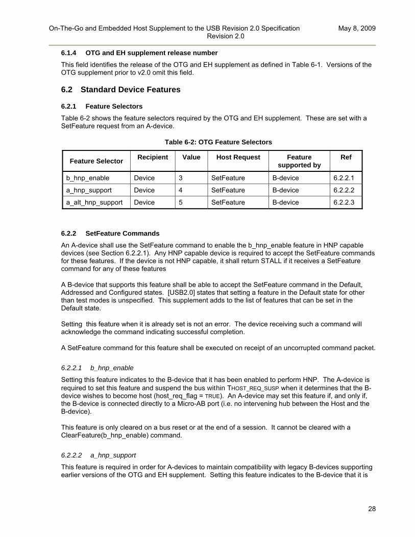
On-The-Go and Embedded Host Supplement to the USB Revision 2.0 Specification May 8, 2009 Revision 2.0
28
6.1.4 OTG and EH supplement release number
This field identifies the release of the OTG and EH supplement as defined in Table 6-1. Versions of the OTG supplement prior to v2.0 omit this field.
6.2 Standard Device Features
6.2.1 Feature Selectors
Table 6-2 shows the feature selectors required by the OTG and EH supplement. These are set with a SetFeature request from an A-device.
Table 6-2: OTG Feature Selectors
Feature Selector Recipient Value Host Request Feature
supported by Ref
b_hnp_enable Device 3 SetFeature B-device 6.2.2.1
a_hnp_support Device 4 SetFeature B-device 6.2.2.2
a_alt_hnp_support Device 5 SetFeature B-device 6.2.2.3
6.2.2 SetFeature Commands
An A-device shall use the SetFeature command to enable the b_hnp_enable feature in HNP capable devices (see Section 6.2.2.1). Any HNP capable device is required to accept the SetFeature commands for these features. If the device is not HNP capable, it shall return STALL if it receives a SetFeature command for any of these features
A B-device that supports this feature shall be able to accept the SetFeature command in the Default, Addressed and Configured states. [USB2.0] states that setting a feature in the Default state for other than test modes is unspecified. This supplement adds to the list of features that can be set in the Default state.
Setting this feature when it is already set is not an error. The device receiving such a command will acknowledge the command indicating successful completion.
A SetFeature command for this feature shall be executed on receipt of an uncorrupted command packet.
6.2.2.1 b_hnp_enable
Setting this feature indicates to the B-device that it has been enabled to perform HNP. The A-device is required to set this feature and suspend the bus within THOST_REQ_SUSP when it determines that the B-device wishes to become host (host_req_flag = TRUE). An A-device may set this feature if, and only if, the B-device is connected directly to a Micro-AB port (i.e. no intervening hub between the Host and the B-device).
This feature is only cleared on a bus reset or at the end of a session. It cannot be cleared with a ClearFeature(b_hnp_enable) command.
6.2.2.2 a_hnp_support
This feature is required in order for A-devices to maintain compatibility with legacy B-devices supporting earlier versions of the OTG and EH supplement. Setting this feature indicates to the B-device that it is

On-The-Go and Embedded Host Supplement to the USB Revision 2.0 Specification May 8, 2009 Revision 2.0
29
directly attached to an A-device port that supports HNP. This feature is not required to be supported by B-devices compliant to this or subsequent versions of the OTG and EH supplement.
The A-device shall set this feature on any legacy B-device, complying with OTG supplement version 1.3 or earlier, that is attached to an A-device port that supports HNP. The A-device shall set this feature at the start of a session, before any B-device configuration is selected. HNP capable B-devices shall not return STALL in response to setting this feature.
If the A-device port that is attached to the B-device is not HNP capable, then the A-device shall not set this feature.
Before putting the legacy B-device into a configuration, the A-device has the following three options with regards to the b_hnp_enable and a_hnp_support features:
set the b_hnp_enable feature set the a_hnp_support feature but not the b_hnp_enable feature set neither the b_hnp_enable nor a_hnp_support features
If the b_hnp_enable feature is set, the B-device is allowed to do HNP, regardless of whether or not the a_hnp_support feature is set.
If the a_hnp_support feature is set, but the b_hnp_enable feature is not set, then it is likely that b_hnp_enable will be set later when the A-device is finished using the bus.
If neither the b_hnp_enable or a_hnp_support features are set before the A-device puts the B-device in a non-default configuration, then the B-device may indicate to the user that HNP is not supported through the current connection.
The a_hnp_support feature is only cleared on a bus reset or at the end of a session. It cannot be cleared with a ClearFeature(a_hnp_support) command.
6.2.2.3 a_alt_hnp_support
This feature is now obsolete.
6.2.3 GetStatus commands
A host is required to use the GetStatus command (Table 6-3), with wIndex set to the OTG status selector (Table 6-4) to request the Host request flag (Table 6-5) from the peripheral (see Section 6.3). If the B-device is not HNP capable, it shall return a STALL if it receives a GetStatus command for the OTG feature selector.
A B-device that supports this feature shall be able to accept the GetStatus command in the Default, Addressed and Configured states. [USB2.0] states that requesting status in the Default state is unspecified. This supplement adds to the list of statuses that can be requested in the Default state and defines a non-zero value of wIndex.
Table 6-3: GetStatus Command Format
bmRequestType bRequest Wvalue wIndex wLength Data
10000000B GET_STATUS Zero OTG status selector
1 OTG Status

On-The-Go and Embedded Host Supplement to the USB Revision 2.0 Specification May 8, 2009 Revision 2.0
30
Table 6-4: OTG status selector
wIndex Status Type
F000H OTG status selector
Table 6-5: OTG Status information
Byte D7 D6 D5 D4 D3 D2 D1 D0
0 Reserved shall be set to zero Host request
flag
6.2.3.1 Host request flag
If bit D0 of the OTG status information (Table 6-5) is set to one this indicates to the host that the peripheral wishes to become host either due to some user interaction or due to an automatic application executing on the peripheral. If bit D0 is reset to zero then the peripheral doesn’t wish to become host.

On-The-Go and Embedded Host Supplement to the USB Revision 2.0 Specification May 8, 2009 Revision 2.0
31
6.3 HNP polling mechanism
Whenever there is an active session between two OTG devices the host is required to execute a GetStatus() with a frequency of THOST_REQ_POLL in order to determine the state of the Host request flag as defined in the OTG status information (see Section 6.2.3). After the host has detected that the Host request flag is set to one the host shall allow the peripheral to take the host role within THOST_REQ_SUSP. If the Host request flag is reset to zero when an A-device has finished its activities it can end the session immediately. Unless an A-device enables b_hnp_enable before entering suspend it shall also continue polling while the bus is suspended.
Table 6-6: HNP polling timing parameters
Parameter Symbol Min Max Units
Polling period for the event flags
THOST_REQ_POLL 1 2 sec
Time from detection of host flag until suspend
THOST_REQ_SUSP 2 sec
A peripheral device should warn its user of the possible consequences before using HNP polling to force a role swap in situations where a badly timed role swap may cause data loss or corruption. For example, a forced role swap in the middle of a long-running low-level disk copy using the Mass Storage Class could result in a corrupted Mass Storage Device. The peripheral device may choose to warn or not to warn the user based on knowledge of the current functions it is providing to the host, as some functions may be more robust to unexpected disconnections than others.
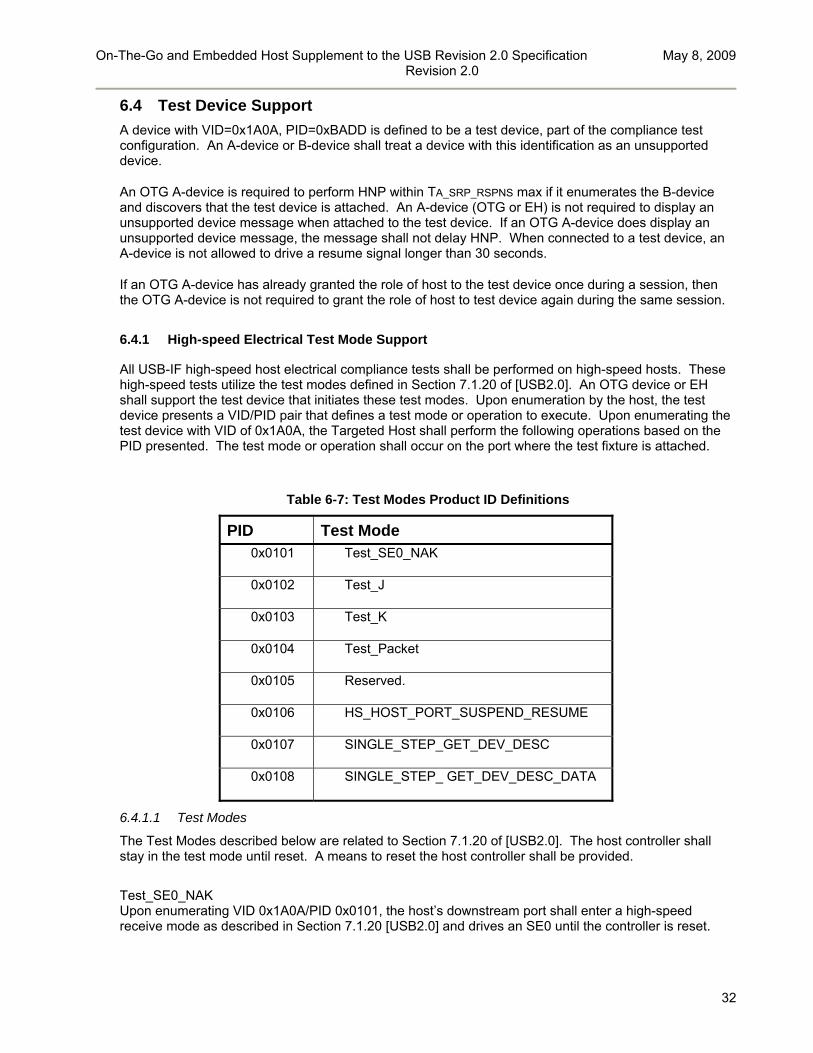
On-The-Go and Embedded Host Supplement to the USB Revision 2.0 Specification May 8, 2009 Revision 2.0
32
6.4 Test Device Support
A device with VID=0x1A0A, PID=0xBADD is defined to be a test device, part of the compliance test configuration. An A-device or B-device shall treat a device with this identification as an unsupported device.
An OTG A-device is required to perform HNP within TA_SRP_RSPNS max if it enumerates the B-device and discovers that the test device is attached. An A-device (OTG or EH) is not required to display an unsupported device message when attached to the test device. If an OTG A-device does display an unsupported device message, the message shall not delay HNP. When connected to a test device, an A-device is not allowed to drive a resume signal longer than 30 seconds.
If an OTG A-device has already granted the role of host to the test device once during a session, then the OTG A-device is not required to grant the role of host to test device again during the same session.
6.4.1 High-speed Electrical Test Mode Support
All USB-IF high-speed host electrical compliance tests shall be performed on high-speed hosts. These high-speed tests utilize the test modes defined in Section 7.1.20 of [USB2.0]. An OTG device or EH shall support the test device that initiates these test modes. Upon enumeration by the host, the test device presents a VID/PID pair that defines a test mode or operation to execute. Upon enumerating the test device with VID of 0x1A0A, the Targeted Host shall perform the following operations based on the PID presented. The test mode or operation shall occur on the port where the test fixture is attached.
Table 6-7: Test Modes Product ID Definitions
PID Test Mode 0x0101 Test_SE0_NAK
0x0102 Test_J
0x0103 Test_K
0x0104 Test_Packet
0x0105 Reserved.
0x0106 HS_HOST_PORT_SUSPEND_RESUME
0x0107 SINGLE_STEP_GET_DEV_DESC
0x0108 SINGLE_STEP_ GET_DEV_DESC_DATA
6.4.1.1 Test Modes
The Test Modes described below are related to Section 7.1.20 of [USB2.0]. The host controller shall stay in the test mode until reset. A means to reset the host controller shall be provided.
Test_SE0_NAK Upon enumerating VID 0x1A0A/PID 0x0101, the host’s downstream port shall enter a high-speed receive mode as described in Section 7.1.20 [USB2.0] and drives an SE0 until the controller is reset.

On-The-Go and Embedded Host Supplement to the USB Revision 2.0 Specification May 8, 2009 Revision 2.0
33
Test_J Upon enumerating VID 0x1A0A/PID 0x0102, the host’s downstream port shall enter a high-speed J state as described in Section 7.1.20 of [USB2.0] until the host controller is reset.
Test_K Upon enumerating VID 0x1A0A/PID 0x0103, the host’s downstream port shall enter a high-speed K state as described in Section 7.1.20 of [USB2.0] until the host controller is reset.
Test_Packet Upon enumerating VID 0x1A0A/PID 0x0104, the host shall begin sending test packets as described in Section 7.1.20 of [USB2.0] until the host controller is reset.
HS_HOST_PORT_SUSPEND_RESUME Upon enumerating VID:0x1A0A/PID 0x0106, the host shall continue sending SOFs for 15 seconds, then suspend the downstream port under test per Section 7.1.7.6.1 of [USB2.0]. After 15 seconds has elapsed, the host shall issue a ResumeK state on the bus, then continue sending SOFs.
SINGLE_STEP_GET_DEVICE_DESCRIPTOR When the host discovers a device with VID:0x1A0A/PID 0x0107, the following steps are executed by the host and the device.
1. The host enumerates the test device, reads VID:0x1A0A/PID 0x0107, then completes its enumeration procedure.
2. The host issues SOFs for 15 seconds allowing the test engineer to raise the scope trigger just above the SOF voltage level.
3. The host sends a complete GetDescriptor(Device) transfer 4. The device ACKs the request, triggering the scope. (Note: SOFs continue.)
SINGLE_STEP_GET_DEVICE_DESCRIPTOR_DATA When the host discovers a device with VID:0x1A0A/PID 0x0108, the following steps are executed by the host and the device.
1. The host enumerates the test device and reads VID:0x1A0A/PID 0x0108, then completes its enumeration procedure
2. After enumerating the device, the host sends GetDescriptor(Device) 3. The device ACKs the request 4. The host issues SOFs for 15 seconds allowing the test engineer to raise the scope trigger just
above the SOF voltage level 5. The host sends an IN packet 6. The device sends data in response to the IN packet, triggering the scope 7. The host sends an ACK in response to the data. (Note: SOFs may follow the IN transaction).

On-The-Go and Embedded Host Supplement to the USB Revision 2.0 Specification May 8, 2009 Revision 2.0
34
7 State Diagrams This section contains state diagrams provided for the reference of OTG device, EH and SRP-capable peripheral-only B-device implementers. In the case of any conflict between these diagrams and the behavior described in the rest of the document, the state machines take precedence.
Figure 7-1 shows the state machine of an OTG A-device. Figure 7-2 shows the state machine of an EH. Figure 7-3 shows the state machine of an OTG B-device. The HNP state machine for an OTG device is equivalent to the OTG A-device state machine combined with the OTG B-device state machine. A state diagram for an SRP-capable peripheral-only B-device is shown in Figure 7-4.
7.1 A-device
The OTG A-device state diagram shown in Figure 7-1 and EH state diagram shown in Figure 7-2 consists of the states listed in Table 7-1 and uses the parameters listed in Table 7-2.There is a transition to the OTG B-device start state (b_idle) that occurs if the cable is detached. When the A-device is in any state except the a_idle state, the A-device transitions to the a_wait_vfall state before transitioning to the a_idle state and then to the b_idle state.
Figure 7-1: A-device State Diagram

On-The-Go and Embedded Host Supplement to the USB Revision 2.0 Specification May 8, 2009 Revision 2.0
35
Figure 7-2: Embedded Host state diagram
Table 7-1: A-device states
State Description Ref
a_idle A-device starting state 7.1.1
a_wait_vrise Wait for VBUS to go into regulation 7.1.2
a_wait_bcon Wait for B-device to signal connection 7.1.3
a_host Acting as a host 7.1.4
a_suspend Bus suspend 7.1.5
a_peripheral Acting as a peripheral 7.1.6
a_wait_vfall Wait for VBUS to drop to VOTG_VBUS_LKG 7.1.7
a_vbus_err Wait for recovery from over-current condition 7.1.8
b_idle B-device starting state 7.2.1
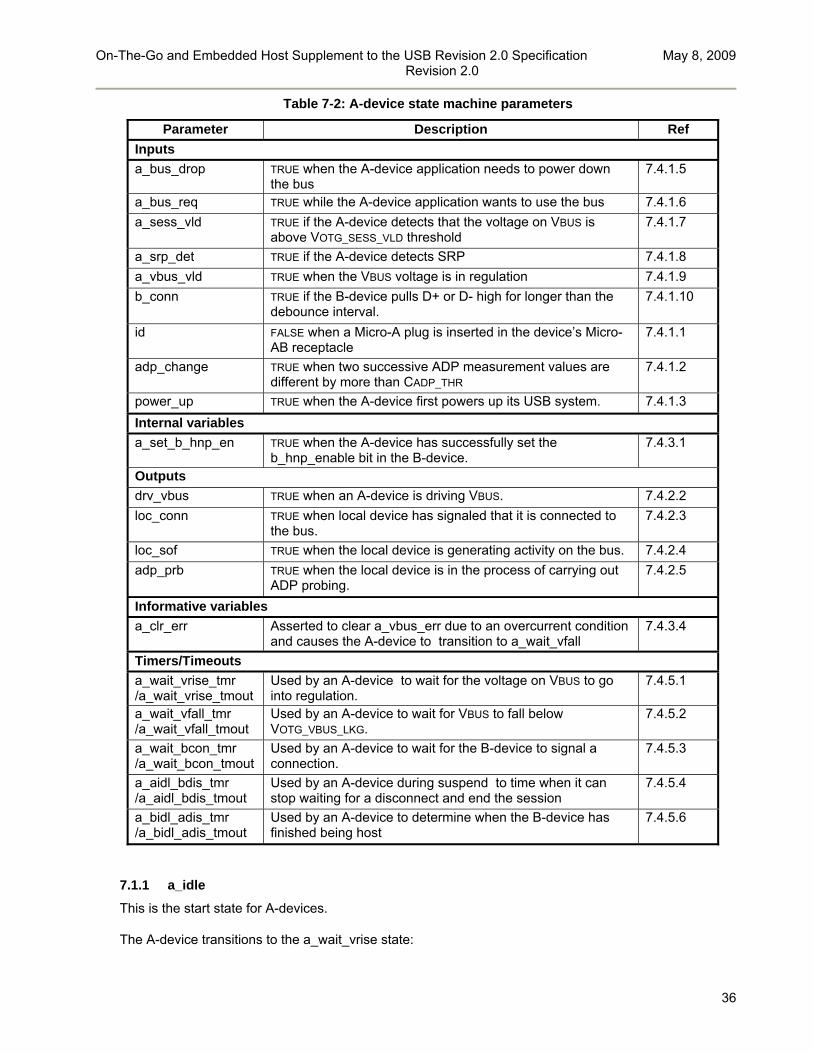
On-The-Go and Embedded Host Supplement to the USB Revision 2.0 Specification May 8, 2009 Revision 2.0
36
Table 7-2: A-device state machine parameters
Parameter Description Ref
Inputs
a_bus_drop TRUE when the A-device application needs to power down the bus
7.4.1.5
a_bus_req TRUE while the A-device application wants to use the bus 7.4.1.6
a_sess_vld TRUE if the A-device detects that the voltage on VBUS is above VOTG_SESS_VLD threshold
7.4.1.7
a_srp_det TRUE if the A-device detects SRP 7.4.1.8
a_vbus_vld TRUE when the VBUS voltage is in regulation 7.4.1.9
b_conn TRUE if the B-device pulls D+ or D- high for longer than the debounce interval.
7.4.1.10
id FALSE when a Micro-A plug is inserted in the device’s Micro-AB receptacle
7.4.1.1
adp_change TRUE when two successive ADP measurement values are different by more than CADP_THR
7.4.1.2
power_up TRUE when the A-device first powers up its USB system. 7.4.1.3
Internal variables
a_set_b_hnp_en TRUE when the A-device has successfully set the b_hnp_enable bit in the B-device.
7.4.3.1
Outputs
drv_vbus TRUE when an A-device is driving VBUS. 7.4.2.2
loc_conn TRUE when local device has signaled that it is connected to the bus.
7.4.2.3
loc_sof TRUE when the local device is generating activity on the bus. 7.4.2.4
adp_prb TRUE when the local device is in the process of carrying out ADP probing.
7.4.2.5
Informative variables
a_clr_err Asserted to clear a_vbus_err due to an overcurrent condition and causes the A-device to transition to a_wait_vfall
7.4.3.4
Timers/Timeouts
a_wait_vrise_tmr /a_wait_vrise_tmout
Used by an A-device to wait for the voltage on VBUS to go into regulation.
7.4.5.1
a_wait_vfall_tmr /a_wait_vfall_tmout
Used by an A-device to wait for VBUS to fall below VOTG_VBUS_LKG.
7.4.5.2
a_wait_bcon_tmr /a_wait_bcon_tmout
Used by an A-device to wait for the B-device to signal a connection.
7.4.5.3
a_aidl_bdis_tmr /a_aidl_bdis_tmout
Used by an A-device during suspend to time when it can stop waiting for a disconnect and end the session
7.4.5.4
a_bidl_adis_tmr /a_bidl_adis_tmout
Used by an A-device to determine when the B-device has finished being host
7.4.5.6
7.1.1 a_idle
This is the start state for A-devices.
The A-device transitions to the a_wait_vrise state:

On-The-Go and Embedded Host Supplement to the USB Revision 2.0 Specification May 8, 2009 Revision 2.0
37
if the A-device application is not wanting to drop the bus (a_bus_drop = FALSE), and any of the following are true: the A-device Application is requesting the bus (a_bus_req = TRUE), or SRP is detected on the bus (a_srp_det = TRUE) or an ADP change has been detected (adp_change = TRUE) or the A-device has only just powered up its USB system (power_up = TRUE).
OTG devices are configured such that a change in id from TRUE to FALSE causes a_bus_req to be asserted unless doing ADP probing (see Section 4.2.4) and that a change in id from FALSE to TRUE causes a transition to the b_idle state. This does not apply to an EH since there is no ID pin in the Standard-A plug.
7.1.2 a_wait_vrise
In this state, the A-device waits for the voltage on VBUS to go into regulation (a_vbus_vld = TRUE). Upon entering this state, the A-device starts a timer (a_wait_vrise_tmr).
The A-device transitions to the a_wait_bcon state:
if the voltage on VBUS is in regulation (a_vbus_vld = TRUE)
The A-device transitions to the a_wait_vfall state:
if the Micro-A plug is detached (id = TRUE, applies to OTG A-devices only), or if the a_wait_vrise_tmr times out (a_wait_vrise_tmout = TRUE) or if the A-device application wants to drop the bus (a_bus_drop = TRUE).
7.1.3 a_wait_bcon
In this state, the A-device waits for the B-device to signal a connection. Upon entering this state, the A-device starts a timer (a_wait_bcon_tmr).
The A-device transitions to the a_wait_vfall state:
if the Micro-A plug is detached (id = TRUE, applies to OTG A-devices only), or if the A-device Application wants to drop the bus (a_bus_drop = TRUE), or if the a_wait_bcon_tmr times out (a_wait_bcon_tmout = TRUE)17.
If the A-device detects the B-device signaling a connection (b_conn = TRUE), then the A-device shall transition to the a_host state and generate a bus reset within TA_BCON_ARST to prepare the B-device for packet traffic.
If the attached device is unsupported due to an overcurrent condition (see Section 4.2.2), then the A-device transitions to the a_vbus_err state.
7.1.4 a_host
In this state the A-device performs the following actions:
17 An A-device may set its a_wait_bcon_tmr to an arbitrarily large value and wait an indefinitely long period of time for the B-device to connect.

On-The-Go and Embedded Host Supplement to the USB Revision 2.0 Specification May 8, 2009 Revision 2.0
38
A-device enumerates B-device if the A-device supports the B-device (see Section 3.4.1), then the A-device sets up
communication with the B-device else if A-device does not support the B-device then the A-device informs the user that the B-
device is not supported and sets a_bus_req = FALSE If the B-device disconnects (b_conn = FALSE) then the A-device transitions from the a_host state to the a_wait_bcon state18.
Under the following conditions the A-device transitions from the a_host state to the a_wait_vfall state.
if the Micro-A plug is detached (id = TRUE, applies to OTG A-devices only), or if the A-device wishes to stop powering VBUS (a_bus_drop = TRUE)
. Under the following conditions, the A-device transitions from the a_host state to the a_suspend state:
if the application on the A-device no longer wishes to use the bus (a_bus_req = FALSE) If the attached device is unsupported due to an overcurrent condition (see Section 4.2.2), then the A-device transitions to the a_vbus_err state.
7.1.5 a_suspend
Upon entering the a_suspend state, if HNP has been enabled (a_set_b_hnp_en = TRUE), an OTG A-device starts the a_aidl_bdis_tmr. This timer can be set to an arbitrarily long time, but shall be longer than TA_AIDL_BDIS min.
An OTG A-device transitions to the a_wait_vfall state:
if the Micro-A plug is detached (id = TRUE, applies to OTG A-devices only), or if the A-device wishes to stop powering VBUS (a_bus_drop = TRUE), or if the a_aidl_bdis_tmr times out (a_aidl_bdis_tmout = TRUE)
An EH will transition to the a_wait_vfall state only if it wishes to stop powering VBUS (a_bus_drop = TRUE)
For the OTG A-device state diagram in Figure 7-1 if the B-device signals a disconnect (b_conn = FALSE), and the A-device was successful in setting b_hnp_enable (a_set_b_hnp_en = TRUE), then the A-device transitions to the a_peripheral state19.
The A-device transitions to the a_host state if a_bus_req is asserted. If a_bus_req is asserted, then the A-device can do a resume. If the A-device detects remote wakeup signaling from the B-device this may cause the A-device to set a_bus_req depending on whether it is prepared to respond to this signalling.
If the B-device signals a disconnect (b_conn = FALSE), and the A-device did not set b_hnp_enable (a_set_b_hnp_en = FALSE) or is an EH, then the A-device transitions to the a_wait_bcon state20.
18 If the same B-device subsequently reconnects the A-device should examine its descriptors to ensure that the B-device is supporting the same device class as when it was previously connected.
19 If b_conn became FALSE due to the removal of the B-plug (rather than a disconnect) then the a_bidl_adis_tmr will subsequently expire and the A-device will transition to a_wait_bcon. After this the a_wait_bcon_tmr will expire and the A-device will transition to a_wait_vfall.

On-The-Go and Embedded Host Supplement to the USB Revision 2.0 Specification May 8, 2009 Revision 2.0
39
If the attached device is unsupported due to an overcurrent condition (see Section 4.2.2), then the A-device transitions to the a_vbus_err state.
7.1.6 a_peripheral
This state is not applicable to an EH. In this state, the A-device signals a connection to the B-device (loc_conn = TRUE) and responds to requests from the OTG B-device. If the A-device is capable of HS operation, then it shall begin the high-speed detection handshake whenever a bus reset is detected.
The A-device transitions from the a_peripheral state to the a_wait_vfall state:
if the Micro-A plug is detached (id = TRUE), or if the A-device wants to power down VBUS (a_bus_drop = TRUE)
The A-device transitions from the a_peripheral state to the a_wait_bcon state if the a_bidl_adis_tmr times out (a_bidl_adis_tmout = TRUE). If the A-device detects more than TA_BIDL_ADIS min of continuous idle (i.e. J_state), on the bus, then the A-device may transition to the a_wait_bcon state. If no activity is detected after TA_BIDL_ADIS max the A-device shall transition back to the a_wait_bcon state.
If the attached device is unsupported due to an overcurrent condition (see Section 4.2.2), then the A-device transitions to the a_vbus_err state.
This is the only state in which the A-device will signal a connection to the B-device.
7.1.7 a_wait_vfall
In this state the A-devices stops driving VBUS (drv_vbus = FALSE) and waits for VBUS to fall to VOTG_VBUS_LKG.
The A-device transitions from the a_wait_vfall state to the a_idle state:
if the a_wait_vfall_tmr expires (a_wait_vfall_tmout = TRUE)
7.1.8 a_vbus_err
In this state, the A-device waits for recovery of the overcurrent condition that caused it to enter this state.
The A-device transitions to the a_wait_vfall state under the following conditions:
if the Micro-A plug is detached (id = TRUE, applies to OTG A-devices only), or if the A-device is no longer capable of powering VBUS (a_bus_drop = TRUE) upon assertion of a_clr_err (nominally by system software),
To preserve the integrity of the circuitry supplying power to VBUS, on entering this state it is recommended that the A-device application no longer requires a drive to VBUS (a_bus_drop = TRUE).
20 If b_conn became FALSE due to the removal of the B-plug rather than a disconnect the a_wait_bcon_tmr will subsequently expire and the A-device will transition to a_wait_vfall.
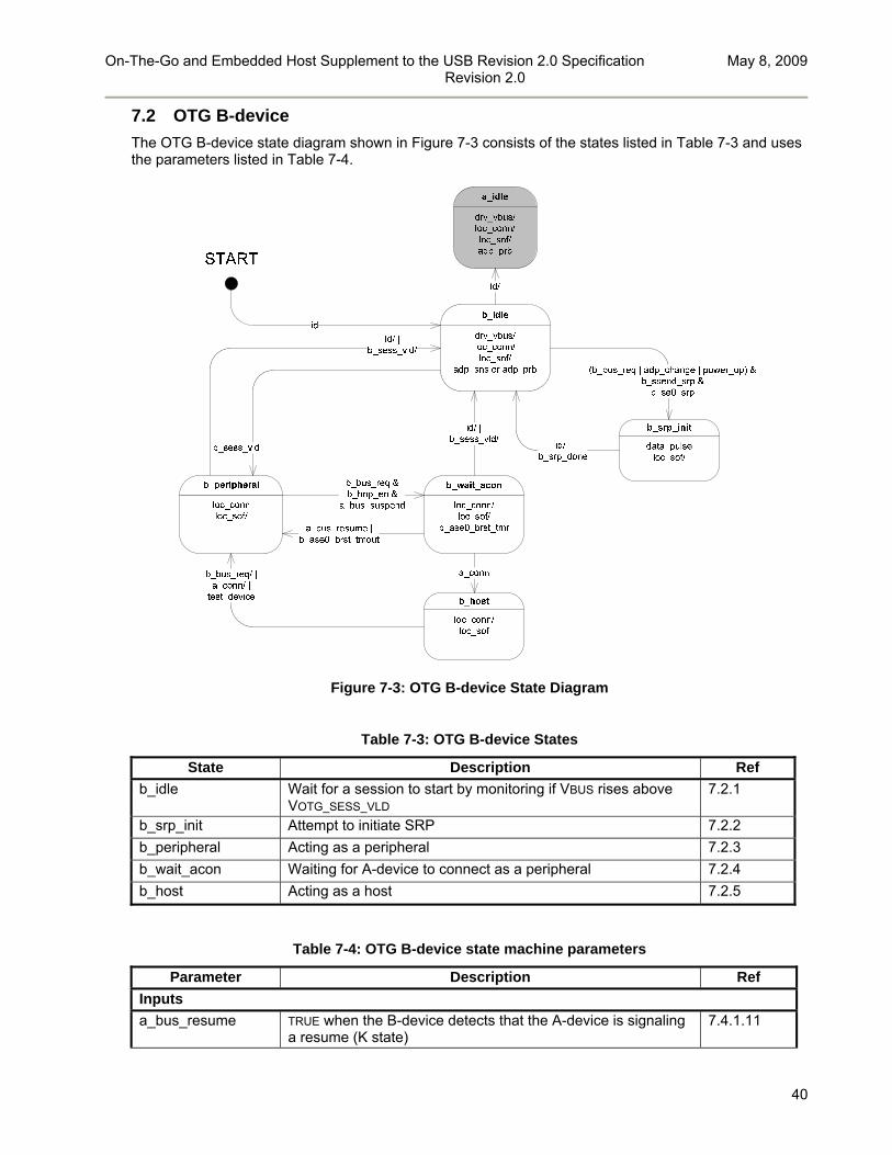
On-The-Go and Embedded Host Supplement to the USB Revision 2.0 Specification May 8, 2009 Revision 2.0
40
7.2 OTG B-device
The OTG B-device state diagram shown in Figure 7-3 consists of the states listed in Table 7-3 and uses the parameters listed in Table 7-4.
Figure 7-3: OTG B-device State Diagram
Table 7-3: OTG B-device States
State Description Ref
b_idle Wait for a session to start by monitoring if VBUS rises above VOTG_SESS_VLD
7.2.1
b_srp_init Attempt to initiate SRP 7.2.2
b_peripheral Acting as a peripheral 7.2.3
b_wait_acon Waiting for A-device to connect as a peripheral 7.2.4
b_host Acting as a host 7.2.5
Table 7-4: OTG B-device state machine parameters
Parameter Description Ref
Inputs
a_bus_resume TRUE when the B-device detects that the A-device is signaling a resume (K state)
7.4.1.11

On-The-Go and Embedded Host Supplement to the USB Revision 2.0 Specification May 8, 2009 Revision 2.0
41
Parameter Description Ref
a_bus_suspend TRUE when the B-device detects that the A-device has put the bus into suspend
7.4.1.12
a_conn TRUE if the B-device detects a connection from the A-device 7.4.1.13
b_bus_req TRUE during the time that the Application running on the B-device wants to use the bus
7.4.1.14
b_se0_srp TRUE when the line has been at SE0 for more than the minimum time before generating SRP
7.4.1.15
b_ssend_srp TRUE when the VBUS has been below VOTG_SESS_VLD for more than the minimum time before generating SRP.
7.4.1.16
b_sess_vld TRUE when the B-device detects that the voltage on VBUS is above VOTG_SESS_VLD
7.4.1.17
id TRUE when a Micro-A plug is not inserted in the device’s Micro-AB receptacle
7.4.1.1
adp_change TRUE when two successive ADP measurement values are significantly different.
7.4.1.2
power_up TRUE when the OTG device first powers up its USB system. 7.4.1.3
test_device TRUE when the B-device is attached to an OTG test device 7.4.1.4
Internal variables
b_srp_done TRUE when the B-device has completed initiating SRP 7.4.3.2
b_hnp_en TRUE when the B-device has accepted the SetFeature(b_hnp_enable)
7.4.3.3
Outputs
data_pulse TRUE when a B-device is performing data line pulsing 7.4.2.1
drv_vbus TRUE when an A-device is driving VBUS. 7.4.2.2
loc_conn TRUE when the local device has signaled that it is connected to the bus.
7.4.2.3
loc_sof TRUE when the local device is generating activity on the bus. 7.4.2.4
adp_prb TRUE when the local device is in the process of doing ADP probing.
7.4.2.5
adp_sns TRUE when the B-device is in the process of carrying out ADP sensing.
7.4.2.6
Timers/Timeouts
b_ase0_brst_tmr/ b_ase0_brst_tmout
Timer used to wait for an A-device to signal a connection. 7.4.5.5
7.2.1 b_idle
In this state, the OTG B-device waits for a session to start by monitoring if VBUS rises above the Session Valid threshold (b_sess_vld = TRUE). If VBUS rises above this threshold, the OTG B-device enters the b_peripheral state and signals a connect (loc_conn = TRUE).
The B-device transitions from the b_idle to the b_srp_init state:
if the Application indicates that it wants to start a session (b_bus_req = TRUE), or an ADP change has been detected (adp_change = TRUE) or the B-device has only just powered up its USB system (power_up = TRUE).

On-The-Go and Embedded Host Supplement to the USB Revision 2.0 Specification May 8, 2009 Revision 2.0
42
and if VBUS has been below the Session End threshold for at least TB_SSEND_SRP (b_ssend_srp = TRUE),
and if the bus has been in the SE0 state for the minimum time before generating SRP (b_se0_srp = TRUE).
If the Micro-A plug is inserted (id = FALSE), then the OTG B-device transitions to the a_idle state and becomes an A-device.
7.2.2 b_srp_init
Upon entering this state, the OTG B-device attempts to initiate a session via SRP. Upon completion, (b_srp_done = TRUE) the OTG B-device returns to the b_idle state, to wait for the A-device to drive VBUS above the Session Valid threshold (b_sess_vld = TRUE).
If the Micro-A plug is inserted (id = FALSE), then the OTG B-device transitions to the b_idle state.
7.2.3 b_peripheral
In this state, the OTG B-device acts as the peripheral, and responds to requests from the A-device.
The OTG B-device transitions to the b_wait_acon state:
if the Application indicates that it wants to start a session (b_bus_req = TRUE) and the A-device has granted the OTG B-device permission (b_hnp_en = TRUE) and the bus is in the Suspend state, (a_bus_suspend = TRUE)
The OTG B-device transitions to the b_idle state:
If a Micro-A plug is inserted (id = FALSE) or if VBUS drops below the Session Valid threshold (b_sess_vld = FALSE)
When a high-speed capable B-device enters this state it shall enable its pull-up on D+. After the B-device enables its pull-up, it shall monitor the state of the bus to determine if a bus reset is being signaled by the A-device. If the pull-up is turned on for TWTRSTHS
21 (Table 7-14 in [USB2.0]) and the bus is in the SE0 state then a reset condition exists. If the B-device is capable of HS, it shall begin the high-speed detection handshake any time that a bus reset condition exists.
7.2.4 b_wait_acon
In this state, the OTG B-device has received a SetFeature(b_hnp_enable) giving it permission to assume the role of host and it has detected that the bus has gone to the Suspend state. Upon entering this state, the OTG B-device turns off its pull-up resistor on D+, starts a timer (b_ase0_brst_tmr), and waits for the A-device to signal a connect.
The OTG B-device returns to the b_peripheral state:
if the b_ase0_brst_tmr expires (b_ase0_brst_tmout = TRUE), or if the B-device detects a K_state on the bus, indicating that the A-device is signaling a resume
(a_bus_resume = TRUE)
21 The TWTRSTHS is a sample point that occurs at a device dependent time after the pull-up resistor is turned on.

On-The-Go and Embedded Host Supplement to the USB Revision 2.0 Specification May 8, 2009 Revision 2.0
43
If the A-device signals a connect (a_conn = TRUE) before the b_ase0_brst_tmr expires, then the B-device transitions to the b_host state. The B-device shall be able to detect the connect from the A-device and transition to the b_host state within TB_ACON_BSE0 max after D+ is detected to be high at the B-device.
The OTG B-device transitions to the b_idle state:
if a Micro-A plug is inserted (id = FALSE) or VBUS drops below the Session Valid threshold (b_sess_vld = FALSE)
7.2.5 b_host
Upon entering this state, the B-device issues a bus reset, and starts generating SOF’s. The B-device may query the A-device for its descriptors.
While the B-device is in this state, the A-device responds to requests from the B-device. If the B-device does not support the A-device, then the B-device shall provide a message to the user informing them of this.
The B-device stops generating bus activity (loc_sof = FALSE) and transitions to the b_peripheral state:
once the B-device has completed its usage of the A-device (b_bus_req = FALSE), or if the B-device detects that the A-device has signaled a disconnect (a_conn = FALSE), or within 30 seconds of the OTG B-device detecting that a test device, as defined in section 6.4, is
attached (test_device =TRUE)

On-The-Go and Embedded Host Supplement to the USB Revision 2.0 Specification May 8, 2009 Revision 2.0
44
7.3 SRP-capable peripheral-only, B-device
The state diagram relevant for SRP-capable peripheral-only B-devices is shown in Figure 7-4. It consists of three distinct states listed in Table 7-5 and uses the parameters listed in Table 7-6.
loc_conn/adp_sns or adp_prb
bp_idle
data_pulse
bp_srp_init
(b_bus_req | adp_change | power_up) & b_ssend_srp &
b_se0_srp
loc_conn
bp_peripheral
b_sess_vld/
START
b_sess_vldb_srp_done
Figure 7-4: SRP-Capable Peripheral-Only B-device State Diagram
Table 7-5: SRP-capable peripheral-only B-device states
State Description Ref
bp_idle Wait for a session to start by monitoring if VBUS rises above VOTG_SESS_VLD
7.3.1
bp_srp_init Attempt to initiate SRP 7.3.2
bp_peripheral Acting as a peripheral 7.3.3
Table 7-6: SRP-capable peripheral-only B-device state machine parameters
Parameter Description Ref
Inputs
b_ssend_srp TRUE when the VBUS has been below VOTG_SESS_VLD for more than the minimum time before generating SRP
7.4.1.16
b_sess_vld TRUE when the B-device detects that the voltage on VBUS is above VOTG_SESS_VLD
7.4.1.17
b_se0_srp TRUE when the line has been at SE0 for more than the minimum time before generating SRP
7.4.1.15
adp_change The ADP change value is TRUE when two successive ADP measurement values are significantly different.
7.4.1.2
power_up TRUE when the OTG device first powers up its USB system. 7.4.1.3
Internal variables
b_srp_done TRUE when the B-device has completed initiating SRP 7.4.3.2
Outputs
data_pulse TRUE when a B-device is performing data line pulsing 7.4.2.1
loc_conn TRUE when the local device has signaled that it is connected to the bus.
7.4.2.3
adp_prb TRUE when the local device is in the process of doing ADP probing.
7.4.2.5

On-The-Go and Embedded Host Supplement to the USB Revision 2.0 Specification May 8, 2009 Revision 2.0
45
Parameter Description Ref
adp_sns TRUE when the B-device is in the process of doing ADP sensing. 7.4.2.6
7.3.1 bp_idle
In this state, the SRP-capable peripheral-only B-device waits for a session to start by monitoring if VBUS rises above the VBUS Session Threshold (b_sess_vld = TRUE). If VBUS rises above this threshold, the SRP-capable peripheral-only B-device enters the bp_peripheral state.
The B-device transitions from the bp_idle state to the bp_srp_init state:
if the Application indicates that it wants to start a session (b_bus_req = TRUE), or an ADP change has been detected (adp_change = TRUE) or the B-device has only just powered up its USB system (power_up = TRUE). and if VBUS has been below the Session End threshold for at least TB_SSEND_SRP (b_ssend_srp
= TRUE), and if the bus has been in the SE0 state for the minimum time before generating SRP
TB_SE0_SRP min(b_se0_srp = TRUE).
7.3.2 bp_srp_init
Upon entering this state, the SRP-capable peripheral-only B-device attempts to start a session via SRP defined. Upon completion (b_srp_done = TRUE) the B-device returns to the bp_idle state, to wait for the A-device to drive VBUS above the Session Valid threshold (b_sess_vld = TRUE).
7.3.3 bp_peripheral
In this state, the B-device acts as a [USB2.0] compliant device.
If VBUS drops below the Session Valid threshold (b_sess_vld = FALSE), then the device transitions to the bp_idle state.

On-The-Go and Embedded Host Supplement to the USB Revision 2.0 Specification May 8, 2009 Revision 2.0
46
7.4 State Machine Parameters
This section describes the inputs, internal variables, timers, and outputs associated with the state machines.
7.4.1 Inputs
7.4.1.1 id
The identification (id) input is FALSE when a Micro-A plug is inserted in the device’s Micro-AB receptacle. Otherwise, this input is TRUE.
7.4.1.2 adp_change
The ADP change value (adp_change) is TRUE when an OTG device, EH or SRP-capable peripheral-only B-device is doing ADP probing (adp_prb = TRUE) and two successive ADP measurement values are different by more than CADP_THR (see section 5.4.2).
The ADP change value (adp_change) is TRUE when a B-device is doing ADP sensing of an ADP-capable A-device and then detects that the ADP probing signal is no longer present.
Both of these indicate a potential change in the attachment status of the remote device. An ADP change will cause the local device to determine whether the remote device is responsive by starting or requesting a new session.
7.4.1.3 power_up
The power up value (power_up) is TRUE when the device first powers up its USB system.
7.4.1.4 test_device
The test device value (test_device) is TRUE when the OTG device or EH is attached to a test device (see Section 6.4).
7.4.1.5 a_bus_drop
The “A-device bus drop” (a_bus_drop) input is TRUE when the Application running on the A-device wants to power down the bus, and is FALSE otherwise. When this input is TRUE, then the a_bus_req input shall be FALSE.
7.4.1.6 a_bus_req
The “A-device bus request” (a_bus_req) input is TRUE during the time that the Application running on the A-device wants to use the bus, and is FALSE when the Application no longer wants to use the bus. a_bus_req can also be set to TRUE in response to remote wakeup signaling from the B-device should the A-device decide to resume the bus.
7.4.1.7 a_sess_vld
The “A-device session valid” (a_sess_vld) input is TRUE if the A-device detects that the voltage on VBUS is above its Session Valid threshold (VOTG_SESS_VLD) (see Table 4-1).

On-The-Go and Embedded Host Supplement to the USB Revision 2.0 Specification May 8, 2009 Revision 2.0
47
7.4.1.8 a_srp_det
The “A-device SRP detect” (a_srp_det) input is TRUE if the A-device detects SRP as defined in Section 5.1. This bit is set when data line pulsing is detected. This variable is set to FALSE on initial power up of the A-device (power_up = TRUE) or whenever the A-device transitions to the a_wait_vfall state.
7.4.1.9 a_vbus_vld
The “A-device VBUS valid” (a_vbus_vld) input is TRUE when the VBUS voltage is in regulation.
7.4.1.10 b_conn
The “B-device connect” (b_conn) variable is used by the A-device as a condition for transitioning between the following states:
On b_conn transition Exit State Enter State
FALSE TRUE a_wait_bcon a_host
TRUE FALSE a_host a_wait_bcon
TRUE FALSE a_suspend a_peripheral
TRUE FALSE a_suspend a_wait_bcon
If b_conn is FALSE, it is set to TRUE if the B-device pulls D+ or D- high for longer than the debounce interval. The debounce interval varies depending on how the a_wait_bcon state was entered, and how long it has been since either D+ or D- has been pulled high. If the a_wait_bcon state was entered from the a_peripheral, a_host or a_suspend states, then the short debounce interval (TA_BCON_SDB) is allowed. If the a_wait_bcon state was entered from the a_wait_vrise state then the long debounce interval (TA_BCON_LDB) is required.
The A-device is only allowed to apply the short debounce to b_conn in a window of time. If the A-device stays in the a_wait_bcon state for longer than TA_BCON_SDB_WIN max, then the long debounce interval applies no matter how the a_wait_bcon state was entered. If the state machine is timing the short debounce interval, changes to D- and D+ do not affect the setting of b_conn if they occur before TLDIS_DSCHG min.
While the A-device is in the a_host or a_suspend state, then the A-device will set b_conn FALSE if the A-device detects that the B-device has disconnected, as described in Section 7.1.7.3 of [USB2.0]. The A-device also sets b_conn to FALSE whenever it transitions to any state other than a_host or a_suspend.
[USB2.0] insures at least 100 ms from the time the device indicates a connect until the device will be reset to start the session. This is not the case for OTG devices. They are not assured in all cases of a 100 ms interval after indicating a connect. When an OTG device signals connect, it shall be prepared to receive the bus reset that starts the session.
7.4.1.11 a_bus_resume
The “A-device bus resume” (a_bus_resume) variable is TRUE when the B-device detects that the A-device is signaling a resume (i.e. K state) on the bus.
If the B-device has transitioned to the b_wait_acon state, then a resume (i.e. K state) from the A-device will cause the B-device to return to the b_peripheral state.

On-The-Go and Embedded Host Supplement to the USB Revision 2.0 Specification May 8, 2009 Revision 2.0
48
7.4.1.12 a_bus_suspend
The “A-device bus suspend” (a_bus_suspend) variable is TRUE when the B-device detects that the A-device has put the bus into suspend22.
If the B-device has been enabled to become host (b_hnp_enable feature has been set), then the B-device uses this variable to transition from the b_peripheral state to the b_wait_acon state
7.4.1.13 a_conn
The “A-device connect” (a_conn) variable is used by the B-device as a condition for entering or exiting the b_host state.
If the B-device is in the b_wait_acon state, the B-device sets a_conn TRUE if the B-device detects a connection from the A-device.
While the B-device is in the b_host state, it will set a_conn FALSE if the B-device detects that the A-device has disconnected, as described in Section 7.1.7.3 of [USB2.0]. The B-device also sets a_conn to FALSE whenever it goes to any state other than the b_host state.
7.4.1.14 b_bus_req
The “B-device bus request” (b_bus_req) input is TRUE during the time that the Application running on the B-device wants to use the bus, and is FALSE when the Application no longer wants to use the bus.
7.4.1.15 b_se0_srp
The “B-device SE0 before SRP” (b_se0_srp) variable is TRUE when the B-device is in the b_idle state, and the line has been at SE0 for more than the minimum time before generating SRP (TB_SE0_SRP) (see Table 5-1)
7.4.1.16 b_ssend_srp
The “B-device session end SRP” (b_ssend_srp) input is TRUE if the B-device detects that the voltage on VBUS has been below the Session Valid threshold (VOTG_SESS_VLD) for at least TB_SSEND_SRP (see Table 4-1).
7.4.1.17 b_sess_vld
The “B-device session valid” (b_sess_vld) input is TRUE when the B-device detects that the voltage on VBUS is above its B-device Session Valid threshold (VOTG_SESS_VLD) (see Table 4-1).
7.4.2 Outputs
7.4.2.1 data_pulse
The “data line pulsing” (data_pulse) signal is TRUE when a B-device is performing data line pulsing (see Section 5.1.3).
22 As per Section 7.1.7.6 of [USB2.0], the downstream device (in this case the B-device) interprets more than 3 ms of idle as an indication that the upstream device has suspended the bus.

On-The-Go and Embedded Host Supplement to the USB Revision 2.0 Specification May 8, 2009 Revision 2.0
49
7.4.2.2 drv_vbus
The “drive VBUS” (drv_vbus) signal is TRUE when an A-device is driving VBUS.
7.4.2.3 loc_conn
The “local connect” (loc_conn) variable is TRUE when the local device has signaled that it is connected to the bus. This variable is FALSE when the local device has signaled that it is disconnected from the bus (see Section 7.4.1.12).
7.4.2.4 loc_sof
The “local SOF” (loc_sof) bit is TRUE when the local device is generating activity on the bus. Activity begins with a bus reset followed by start of frame packets (SOF’s) or low-speed keep-alives or any other bus activity that occurs with enough frequency to prevent the peripheral device from sensing a lack of bus activity.
7.4.2.5 adp_prb
The ADP probe variable (adp_prb) is TRUE when the local device is doing ADP probing (see section 5.4.2).
A B-device also has the option of doing ADP sensing if the remote A-device is doing ADP probing (see Section 5.4.3).
7.4.2.6 adp_sns
The ADP sense variable (adp_sns) is TRUE when the local device is doing ADP sensing. This output is used in preference to adp_prb when the B-device detects that the A-device is doing ADP probing (see Section 5.4.3).
7.4.3 Internal Variables
7.4.3.1 a_set_b_hnp_en
The “A-device set b_hnp_enable” (a_set_b_hnp_en) bit is TRUE when the A-device has successfully set the b_hnp_enable bit in the B-device. The A-device sets this bit after it successfully sends a SetFeature (b_hnp_enable) command to the B-device. The A-device clears a_set_b_hnp_en, upon entry into the a_wait_bcon state or when the A-device asserts a bus reset.
7.4.3.2 b_srp_done
The “B-device SRP done” (b_srp_done) bit is TRUE when the B-device has completed initiating SRP.
7.4.3.3 b_hnp_en
The “B-device set b_hnp_enable” (b_hnp_en) bit is TRUE when the B-device has accepted the SetFeature(b_hnp_enable). b_hnp_en is cleared on a bus reset or when b_sess_vld is FALSE (see Section 6.2.2.1).
7.4.3.4 a_clr_err
The A-Device clear error (a_clr_err) is asserted to clear a_vbus_err due to an overcurrent condition and causes the A-device to transition to a_wait_vfall.

On-The-Go and Embedded Host Supplement to the USB Revision 2.0 Specification May 8, 2009 Revision 2.0
50
7.4.4 Informative Variables
The following variables are representations of behavior that is internal to the device.
a_bus_req a_bus_drop a_clr_err b_bus_req
While the device shall demonstrate behavior related to these variables (i.e. the A-device shall turn on VBUS in response to some activity, corresponding to receiving an a_bus_req) the actual implementation and use of these variables is at the designer’s discretion. The inclusion of these variables within the following state machines is not meant to convey required operation, but is an informative example only to show the behavior of the system.
7.4.5 Timers
The HNP state machines make use of the timers in Table 7-7. All timers are started on entry to and reset on exit from their associated states.
Table 7-7: OTG Device Timers
Timer Timeout Time Timeout Indication Associated State
a_wait_vrise_tmr TA_VBUS_RISE a_wait_vrise_tmout a_wait_vrise
a_wait_vfall_tmr TSSEND_LKG a_wait_vfall_tmout a_wait_vfall
a_wait_bcon_tmr TA_WAIT_BCON a_wait_bcon_tmout a_wait_bcon
a_aidl_bdis_tmr TA_AIDL_BDIS a_aidl_bdis_tmout a_suspend
b_ase0_brst_tmr TB_ASE0_BRST b_ase0_brst_tmout b_wait_acon
a_bidl_adis_tmr TA_BIDL_ADIS a_bidl_adis_tmout a_peripheral
7.4.5.1 a_wait_vrise_tmr
This timer is used by an A-device in the a_wait_vrise state to wait for the voltage on VBUS to go into regulation (a_vbus_vld = TRUE). If VBUS is not in regulation before and after TA_VBUS_RISE (a_wait_vrise_tmout = TRUE), then this is an indication that the B-device is drawing too much current.
7.4.5.2 a_wait_vfall_tmr
This timer is used by an A-device in the a_wait_vfall state while waiting for the voltage on VBUS to fall below the VBUS leakage voltage VOTG_VBUS_LKG. When this timer expires the A-device transitions to a_idle.
7.4.5.3 a_wait_bcon_tmr
This timer is used by an A-device in the state to wait for the B-device to signal a connection, (b_conn = TRUE). If the B-device does not connect before TA_WAIT_BCON, (a_wait_bcon_tmout = TRUE), then the A-device is allowed to stop waiting for a connection.
On-The-Go and Embedded Host Supplement to the USB Revision 2.0 Specification May 8, 2009 Revision 2.0
51
7.4.5.4 a_aidl_bdis_tmr
This timer is started by an A-device when it enters the a_suspend state if HNP has been enabled (a_set_b_hnp_en = TRUE). If the A-device does not detect a disconnect before TA_AIDL_BDIS (a_aidl_bdis_tmout = TRUE), then the A-device is allowed to stop waiting for a disconnect and end the session.
7.4.5.5 b_ase0_brst_tmr
This timer is used by a B-device in the b_wait_acon state, to wait for an A-device to signal a connection, (a_conn = TRUE). If the A-device does not connect before TB_ASE0_BRST (b_ase0_brst_tmout = TRUE), then the B-device shall return to the b_peripheral state.
7.4.5.6 a_bidl_adis_tmr
This timer is used by the A-device in the a_peripheral state. The “B-device idle timeout” (a_aidl_bdis_tmout) variable is TRUE when the A-device detects that the B-device has been idle for a sufficient amount of time to allow the B-device to have performed a reset23. The A-device uses this variable to transition from the a_peripheral state to the a_wait_bcon state
23 In Section 7.1.7.6 of [USB2.0] the downstream device (in this case the A-device) interprets more than 3 ms of idle as an indication that the upstream device has suspended the bus. TA_BIDL_ADIS min is much larger than this value. This means that it is possible for the B-device to suspend and resume the bus provided that this is for less than TA_BIDL_ADIS min. Suspending the bus for more than TA_BIDL_ADIS max indicates that the B-device no longer wants to act as host.

On-The-Go and Embedded Host Supplement to the USB Revision 2.0 Specification May 8, 2009 Revision 2.0
52
8 Embedded Host Requirements EHs are required to follow the rules for capability limitation including support for a TPL as defined in Section 3.4 and [OTGand EHCompliance2.0]. In addition they are also allowed to support SRP and ADP as defined in Sections 5.1 and 5.4. EHs are not allowed to support HNP defined in Section 5.2.
EHs are required to follow the USB 2.0 specification except where certain features are not required for the proper functioning of the intended set of supported peripherals. EHs are at liberty to choose whether they leave VBUS always powered, and whether they support SRP or ADP. These EHs must comply with:
the rules for connectors in Section 3.1.3 capability limitation in Section 3.4 “No silent failures” requirements in Section 3.5 and [OTGand EHCompliance2.0].
EHs which support SRP and/or ADP or place limitations on their functionality based on their TPL (e.g. output power) must comply with all of the electrical and protocol requirements of an OTG A-device except for those relating to HNP. This includes:
Key features detailed in Section 3 (excluding the Micro-AB connector and HNP related features) Operation as detailed in Sections 2, A.3.1, and A.3.2 Electrical characteristics for A-device host operation detailed in Sections 4.1 and 4.2. Support for SRP as detailed for the A-device in Section 5.1 Support for suspend, resume, remote wakeup as defined in [USB2.0] Support for ADP as detailed for the A-device in Section 5.4 Embedded Host state machine as detailed in Section 7.1
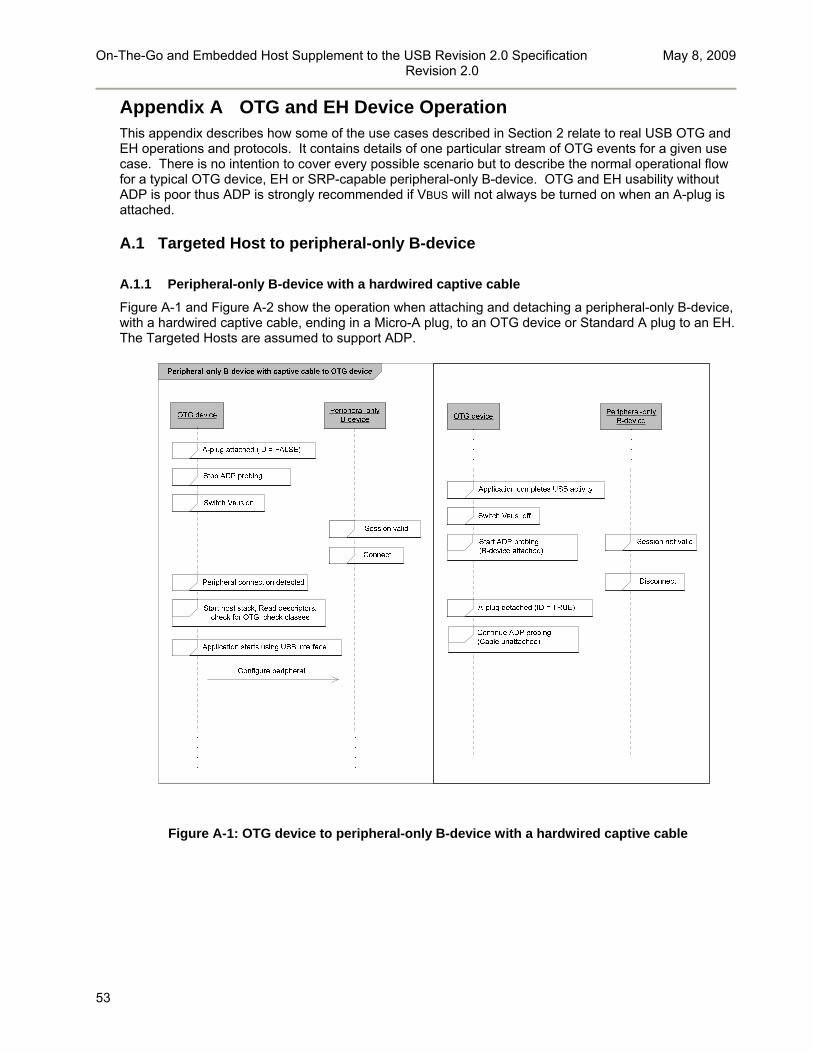
On-The-Go and Embedded Host Supplement to the USB Revision 2.0 Specification May 8, 2009 Revision 2.0
53
Appendix A OTG and EH Device Operation This appendix describes how some of the use cases described in Section 2 relate to real USB OTG and EH operations and protocols. It contains details of one particular stream of OTG events for a given use case. There is no intention to cover every possible scenario but to describe the normal operational flow for a typical OTG device, EH or SRP-capable peripheral-only B-device. OTG and EH usability without ADP is poor thus ADP is strongly recommended if VBUS will not always be turned on when an A-plug is attached.
A.1 Targeted Host to peripheral-only B-device
A.1.1 Peripheral-only B-device with a hardwired captive cable
Figure A-1 and Figure A-2 show the operation when attaching and detaching a peripheral-only B-device, with a hardwired captive cable, ending in a Micro-A plug, to an OTG device or Standard A plug to an EH. The Targeted Hosts are assumed to support ADP.
Figure A-1: OTG device to peripheral-only B-device with a hardwired captive cable

On-The-Go and Embedded Host Supplement to the USB Revision 2.0 Specification May 8, 2009 Revision 2.0
54
Figure A-2: Embedded Host to peripheral-only B-device with captive cable

On-The-Go and Embedded Host Supplement to the USB Revision 2.0 Specification May 8, 2009 Revision 2.0
55
A.1.2 Peripheral-only B-device with a detachable cable
Figure A-3 and Figure A-4 show the operation when attaching and detaching a peripheral-only B-device, with a detachable cable (B-type or captive termination), ending in a Micro-A plug, to an OTG device or Standard-A plug to an EH. The Targeted Host is assumed to support ADP24.
OTG device
Peripheral-only B-device with detachable cable to OTG device
Start host stack, Read descriptors, check for OTG, check classes
Configure peripheral
B-plug attached
ADP change
Switch VBUS on
Peripheral connection detected
Connect
Session valid
Continue ADP probing(B-device unattached)
Application starts using USB interface
No cable
OTG device
Switch VBUS off
B-plug detached
ADP change
Switch VBUS on
No peripheral detected
Switch VBUS off
A-plug detached
Session not valid
Disconnect
Start ADP probing(B-device unattached)
Start ADP probing(B-device atttached)
Application completes USB activity
Continue ADP probing(Cable unattached)
Stop ADP probing
Peripheral-only B-device
Peripheral-only B-device
Switch VBUS on
Stop ADP probing
A-plug attached (ID = FALSE)
Start ADP probing(B-device unattached)
B-device connection timeout
switch VBUS off
Figure A-3: Peripheral-only B-device with a detachable cable to OTG device
24 If the Targeted Host does not support ADP it has no way to detect the B-plug attachment. The Targeted Host can either leave VBUS turned on or raise VBUS in response to a user input (see Section 2.1.1).

On-The-Go and Embedded Host Supplement to the USB Revision 2.0 Specification May 8, 2009 Revision 2.0
56
EH
Peripheral-only B-device with detachable cable to EH
Start host stack, Read descriptors, check for OTG, check classes
Configure peripheral
B-plug attached
ADP change
Switch VBUS on
Peripheral connection detected
Connect
A-plug attached
Session valid
Continue ADP probing(B-device unattached)
Application starts using USB interface
No cable
EH
Switch VBUS off
B-plug detached
ADP change
Switch VBUS on
No peripheral detected
Switch VBUS off
A-plug detached
Session not valid
Disconnect
Start ADP probing(B-device unattached)
Start ADP probing(B-device atttached)
Application completes USB activity
Continue ADP probing(Cable unattached)
Stop ADP probing
Peripheral-only B-device
Peripheral-only B-device
Figure A-4: Peripheral-only B-device with a detachable cable to EH

On-The-Go and Embedded Host Supplement to the USB Revision 2.0 Specification May 8, 2009 Revision 2.0
57
A.1.3 ADP-capable peripheral-only B-device to ADP-capable Targeted Host
Figure A-5 shows the operation when attaching and detaching an ADP-capable peripheral-only B-device, with non-captive cabling, to a Targeted Host which also supports ADP.
Generate SRP
Targeted Host
ADP-capable peripheral-only B-device to Targeted Host with ADP
Start host stack, Read descriptors, check for OTG, check classes
Configure peripheral
B-plug attached
ADP change
Switch VBUS on
Peripheral connection detected
Connect
A-plug attached
Session valid
Continue ADP probing(B-device unattached)
Application starts using USB interface
No cable
Targeted Host
Switch VBUS off
B-plug detached
ADP change
Switch VBUS on
No peripheral detected
Switch VBUS off
A-plug detached
Session not valid
Disconnect
Start ADP probing(B-device unattached)
Start ADP probing(B-device atttached)
Application completes USB activity
Continue ADP probing(Cable unattached)
ADP change
Stop ADP probing
Start ADP sensing
No ADP sensed
Start ADP probing(Cable unattached)
Peripheral-only B-device
Peripheral-only B-device
Switch VBUS on
No peripheral detected
Switch VBUS off
OTG A-device only (see footnote)
Figure A-5: ADP-Capable peripheral-only B-device to Targeted Host with ADP25
25 An EH without ADP capability will not be able to switch on VBUS in response to cable attachment.

On-The-Go and Embedded Host Supplement to the USB Revision 2.0 Specification May 8, 2009 Revision 2.0
58
A.1.4 ADP-Capable peripheral-only B-device to Targeted Host without ADP
Figure A-6 shows the operation when attaching and detaching an ADP-capable peripheral-only B-device, with non-captive cabling. The peripheral is attached to a Targeted Host which doesn’t support ADP but has SRP support.
Figure A-6: ADP-Capable peripheral-only B-device to Targeted Host without ADP26
26 An EH without ADP capability will not be able to switch on VBUS in response to cable attachment.

On-The-Go and Embedded Host Supplement to the USB Revision 2.0 Specification May 8, 2009 Revision 2.0
59
A.1.5 User interaction with Targeted Host
Figure A-7 shows the operation when no session is active and the user interacts with an ADP-capable Targeted Host attached to a peripheral-only B-device with ADP support. The Targeted Host should check the device classes supported by the peripheral-only B-device at the start of every session since the B-device may have changed its mode of operation.
Targeted Host
Switch VBUS on
Start host stack, Read descriptors, check for OTG, check classes
Configure B-device
Start application
Stop ADP probing
Connect
Stop application
Stop ADP sensing
Targeted Host user interaction
Start ADP sensing
Switch VBUS off
Start ADP probing(ADP = B-device attached)
Session valid
Peripheral connection detected
Session not valid
Peripheral-only B-device
Figure A-7: User interaction with a Targeted Host when no session is active

On-The-Go and Embedded Host Supplement to the USB Revision 2.0 Specification May 8, 2009 Revision 2.0
60
A.2 OTG device to OTG device
A.2.1 Attachment
Figure A-8 shows the operation when attaching two OTG devices, and assumes full support for HNP, SRP, and ADP (see also Section 3.4). In this case the devices are attached and then proceed to each take the host role in order to discover each other’s capabilities.
Figure A-8: Attachment of OTG devices27
27 It is recommended but not mandatory for the B-device to take the host role and carry out its own discovery on attachment. This helps the B-device to determine whether it makes sense for it to carry out HNP at a later stage based on the A-device’s capabilities as a peripheral.
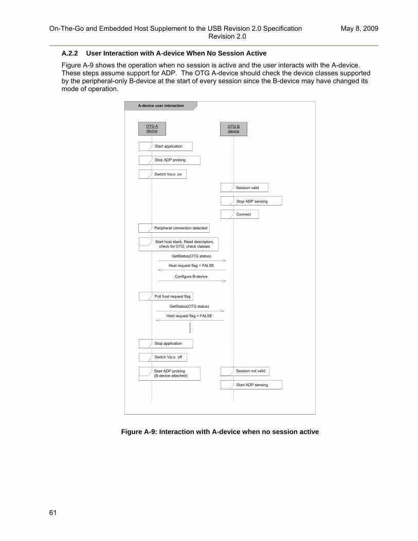
On-The-Go and Embedded Host Supplement to the USB Revision 2.0 Specification May 8, 2009 Revision 2.0
61
A.2.2 User Interaction with A-device When No Session Active
Figure A-9 shows the operation when no session is active and the user interacts with the A-device. These steps assume support for ADP. The OTG A-device should check the device classes supported by the peripheral-only B-device at the start of every session since the B-device may have changed its mode of operation.
OTG A device
OTG B device
Switch VBUS on
Start host stack, Read descriptors, check for OTG, check classes
Configure B-device
Start application
GetStatus(OTG status)
Host request flag = FALSE
Poll host request flag
GetStatus(OTG status)
Host request flag = FALSE
Stop ADP probing
Connect
Stop application
Stop ADP sensing
A-device user interaction
Start ADP sensing
Switch VBUS off
Start ADP probing(B-device attached)
Session valid
Peripheral connection detected
Session not valid
Figure A-9: Interaction with A-device when no session active
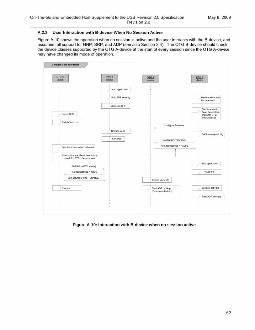
On-The-Go and Embedded Host Supplement to the USB Revision 2.0 Specification May 8, 2009 Revision 2.0
62
A.2.3 User Interaction with B-device When No Session Active
Figure A-10 shows the operation when no session is active and the user interacts with the B-device, and assumes full support for HNP, SRP, and ADP (see also Section 3.4). The OTG B-device should check the device classes supported by the OTG A-device at the start of every session since the OTG A-device may have changed its mode of operation.
OTG A device
OTG B device
B-device user interaction
Switch VBUS on
SetFeature( B_HNP_ENABLE )
Start application
Generate SRP
Suspend
Host request flag = TRUE
Stop ADP sensing
Connect
Peripheral connection detected
Session valid
Detect SRP
Start host stack, Read descriptors, check for OTG, check classes
GetStatus(OTG status)
OTG A device
OTG B device
Configure A-device
Poll host request flag
Start host stack, Read descriptors, check for OTG, check classes
GetStatus(OTG status)
Host request flag = FALSE
Stop application
Suspend
Start ADP sensing
Switch VBUS off
Start ADP probing(B-device attached)
Session not valid
Perform HNP and become host
Figure A-10: Interaction with B-device when no session active

On-The-Go and Embedded Host Supplement to the USB Revision 2.0 Specification May 8, 2009 Revision 2.0
63
A.2.4 User Interaction with A-device When Session Active
Figure A-11 shows the operation when the B-device is active as host and the user interacts with the A-device, and assumes full support for HNP (see also Section 3.4).
OTG A device
OTG B device
A-device user interaction
Configure B-device
Start application
Poll host request flag
Complete HNP process by suspending and becoming peripheral
Start host stack, Read descriptors, check for OTG, check classes
GetStatus(OTG status)
Acting as hostActing as peripheral
Host request flag = TRUE
GetStatus(OTG status)
Host request flag = FALSE
GetStatus(OTG status)
Host request flag = FALSE
Set host request flag to TRUE
Figure A-11: Interaction with A-device during active session

On-The-Go and Embedded Host Supplement to the USB Revision 2.0 Specification May 8, 2009 Revision 2.0
64
A.2.5 User Interaction with B-device When Session Active
Figure A-12 shows the operation when the A-device is active as host and the user interacts with the B-device, and assumes full support for HNP (see also Section 3.4).
Figure A-12: Interaction with B-device during active session

On-The-Go and Embedded Host Supplement to the USB Revision 2.0 Specification May 8, 2009 Revision 2.0
65
A.3 Operation on power up
The following sections describe the operation of an OTG device or EH immediately after its USB system has been powered up.
A.3.1 Power up of an unattached ADP-capable A-device
Figure A-13 shows the operation of an A-device after powering up its USB function when it is unattached, and assumes support for ADP. An EH needs ADP support in order to detect A-plug attachment when VBUS is not powered.
Figure A-13: Power up of an unattached ADP-capable A-device
A.3.2 Power up of attached ADP-capable A-device
Figure A-14 shows the operation of an A-device after powering up its USB function when it is attached, and assumes support for ADP. An EH needs ADP support in order to detect A-plug attachment when VBUS is not powered.
Figure A-14: Power up of an attached ADP-capable A-device

On-The-Go and Embedded Host Supplement to the USB Revision 2.0 Specification May 8, 2009 Revision 2.0
66
A.3.3 Power up of an unattached ADP-capable B-device
Figure A-15 shows the operation of an ADP-capable B-device after powering up its USB function when it is unattached, and assumes support for ADP.
Figure A-15: Power up of an unattached ADP-capable B-device
A.3.4 Power up of an attached ADP-capable B-device
Figure A-16 shows the operation of an ADP-capable B-device after powering up its USB function when it is attached, and assumes support for ADP.
Figure A-16: Power up of an attached ADP-capable B-device
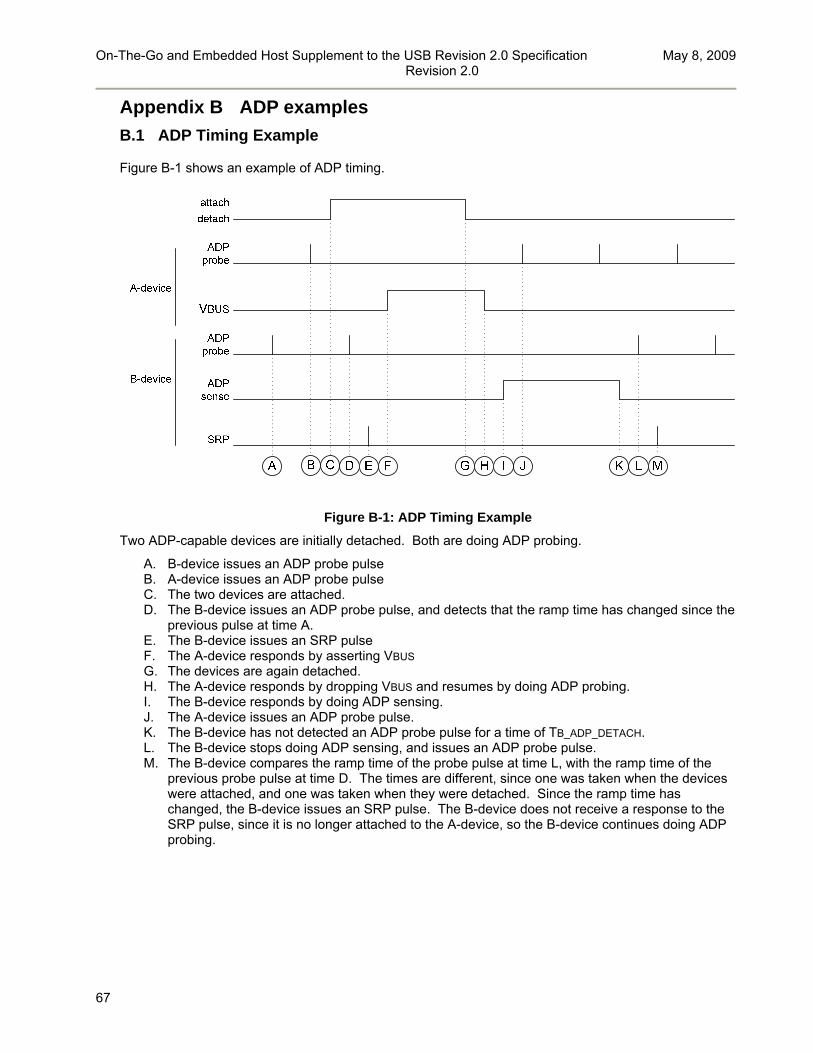
On-The-Go and Embedded Host Supplement to the USB Revision 2.0 Specification May 8, 2009 Revision 2.0
67
Appendix B ADP examples
B.1 ADP Timing Example
Figure B-1 shows an example of ADP timing.
Figure B-1: ADP Timing Example
Two ADP-capable devices are initially detached. Both are doing ADP probing.
A. B-device issues an ADP probe pulse B. A-device issues an ADP probe pulse C. The two devices are attached. D. The B-device issues an ADP probe pulse, and detects that the ramp time has changed since the
previous pulse at time A. E. The B-device issues an SRP pulse F. The A-device responds by asserting VBUS G. The devices are again detached. H. The A-device responds by dropping VBUS and resumes by doing ADP probing. I. The B-device responds by doing ADP sensing. J. The A-device issues an ADP probe pulse. K. The B-device has not detected an ADP probe pulse for a time of TB_ADP_DETACH. L. The B-device stops doing ADP sensing, and issues an ADP probe pulse. M. The B-device compares the ramp time of the probe pulse at time L, with the ramp time of the
previous probe pulse at time D. The times are different, since one was taken when the devices were attached, and one was taken when they were detached. Since the ramp time has changed, the B-device issues an SRP pulse. The B-device does not receive a response to the SRP pulse, since it is no longer attached to the A-device, so the B-device continues doing ADP probing.
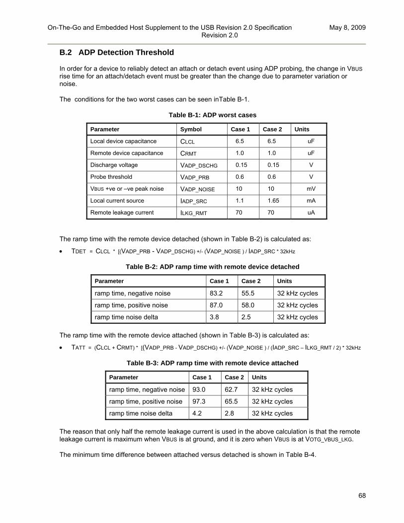
On-The-Go and Embedded Host Supplement to the USB Revision 2.0 Specification May 8, 2009 Revision 2.0
68
B.2 ADP Detection Threshold
In order for a device to reliably detect an attach or detach event using ADP probing, the change in VBUS rise time for an attach/detach event must be greater than the change due to parameter variation or noise.
The conditions for the two worst cases can be seen inTable B-1.
Table B-1: ADP worst cases
Parameter Symbol Case 1 Case 2 Units
Local device capacitance CLCL 6.5 6.5 uF
Remote device capacitance CRMT 1.0 1.0 uF
Discharge voltage VADP_DSCHG 0.15 0.15 V
Probe threshold VADP_PRB 0.6 0.6 V
VBUS +ve or –ve peak noise VADP_NOISE 10 10 mV
Local current source IADP_SRC 1.1 1.65 mA
Remote leakage current ILKG_RMT 70 70 uA
The ramp time with the remote device detached (shown in Table B-2) is calculated as:
TDET = CLCL * [(VADP_PRB - VADP_DSCHG) +/- (VADP_NOISE ) / IADP_SRC * 32kHz
Table B-2: ADP ramp time with remote device detached
Parameter Case 1 Case 2 Units
ramp time, negative noise 83.2 55.5 32 kHz cycles
ramp time, positive noise 87.0 58.0 32 kHz cycles
ramp time noise delta 3.8 2.5 32 kHz cycles
The ramp time with the remote device attached (shown in Table B-3) is calculated as:
TATT = (CLCL + CRMT) * [(VADP_PRB - VADP_DSCHG) +/- (VADP_NOISE ) / (IADP_SRC – ILKG_RMT / 2) * 32kHz
Table B-3: ADP ramp time with remote device attached
Parameter Case 1 Case 2 Units
ramp time, negative noise 93.0 62.7 32 kHz cycles
ramp time, positive noise 97.3 65.5 32 kHz cycles
ramp time noise delta 4.2 2.8 32 kHz cycles
The reason that only half the remote leakage current is used in the above calculation is that the remote leakage current is maximum when VBUS is at ground, and it is zero when VBUS is at VOTG_VBUS_LKG.
The minimum time difference between attached versus detached is shown in Table B-4.

On-The-Go and Embedded Host Supplement to the USB Revision 2.0 Specification May 8, 2009 Revision 2.0
69
Table B-4: Difference between ADP attach and detach
Parameter Case 1 Case 2 Units
attach vs detach time 6.1 4.7 32 kHz cycles
Notes on ADP parameter values:
The threshold for detecting an attach or detach event needs to be less than the attach versus detach time, but greater than the noise delta time.
For case one, the threshold needs to be between 3.8 cycles and 6.1 cycles when detached, and between 4.2 cycles and 6.1 cycles when attached.
For case two, the threshold needs to be between 2.5 cycles and 4.7 cycles when detached, and between 2.8 cycles and 4.7 cycles when attached.
It is recommended that the threshold time be set by using 5.5% of the measured ramp time, and then rounding up to the nearest half cycle of a 32kHz clock.
B.3 ADP Current Consumption
This section calculates the current consumption of an ADP circuit in a B-device with no remote device attached, assuming the parameter values in Table B-5.
Table B-5: ADP current consumption assumed parameter values
Parameter Symbol Value Units
VBUS capacitance CADP_VBUS 4.7 uF
ADP probing voltage VADP_PRB 0.7 V
ADP discharge voltage VADP_DSCHG 0.1 V
Comparator and reference current consumption ICOMP_REF 50 uA
B-device ADP probing period TB_ADP_PRB 2 sec
VBUS resistance ROTG_VBUS 10 K
VBUS leakage source current IVBUS_LKG_SRC 70 uA
ADP sink current IADP_SINK 1.25 mA
ADP source current IADP_SRC 1.25 mA
Between ADP pulses, the leakage voltage on VBUS is:
VVBUS_LKG = IVBUS_LKG_SRC x ROTG_VBUS = 70uA x 10k = 700mV
At the start of an ADP probe cycle, the ADP circuit must first discharge VBUS. The time required to discharge VBUS from VVBUS_LKG to VADP_DSCHG is, to a first approximation:
TADP_DSCHG = (VVBUS_LKG - VADP_DSCHG) x CADP_VBUS / (IADP_SINK - IVBUS_LKG_SRC + .5 x
VVBUS_LKG / ROTG_VBUS)
TADP_DSCHG = (.7V - .1V) x 4.7uF / (1.25mA - 70uA + .5 x .7V / 10k) = 2.2 msec
TADP_RISE (the time required to charge VBUS from VADP_DSCHG to VADP_PRB) is the same as the discharge time, TADP_DSCHG, or 2.2msec.
The average current consumption of the charging and discharging circuitry is then:

On-The-Go and Embedded Host Supplement to the USB Revision 2.0 Specification May 8, 2009 Revision 2.0
70
IADP_AVG = [ ICOMP_REF x (TADP_DSCHG + TADP_RISE) + IADP_SRC x TADP_RISE ] / TB_ADP_PRB
IADP_AVG = [ 50uA x (2.2ms + 2.2ms) + 1.25mA x 2.2ms ] / 2 sec = 1.5 uA
Additional current will also be consumed by the control and timing circuitry.