on the feasibility of carbon nanotube windings for...
TRANSCRIPT

On the Feasibility of Carbon Nanotube Windings forElectrical Machines – Case Study for a Coreless
Axial Flux MotorVandana Rallabandi, Narges Taran, Dan M. IonelDepartment of Electrical and Computer Engineering,
University of Kentucky,Lexington, Kentucky, USA
Email: [email protected]
John F. EasthamUniversity of Bath,Claverton Down,
Bath, UKEmail: [email protected]
Abstract—The latest developments in carbon nanotube (CNT)wires and yarns attract great interest for potential applicationto electromagnetic devices, such as electrical machines andtransformers. The CNT material properties are largely differentfrom copper and aluminum in terms of electrical conductivity,mass density, and thermal transfer, creating a new designparadigm for which the traditional rules and device topologies nolonger apply. This paper proposes a brushless permanent magnetmultidisc axial flux construction with coreless stator and specialwindings and minimal rotor back iron, as a suitable topologyfor CNT winding application. Specific analytical closed-formsizing equations, as a function of winding electric conductivity,machine dimensions, and operating speed/frequency, are derivedand employed in a systematic comparative study over a range ofkW power ratings and speeds between 1,000 and 10,000 rpm. Thenumerical study is complemented by 3D and 2D electromagneticFEA. The results show that the designs with CNT windings mayhave substantially higher specific power per mass, particularlyat high rotational speeds and/or supply frequency, where thecombined effect of DC and AC conduction losses in the windingsis significant.
Index Terms—axial flux machine, coreless motor, sizing equa-tions, carbon nanotube conductors, CNT wire, CNT yarn.
I. INTRODUCTION
Carbon nanotubes (CNT) are tubular cylinders of a planarhexagonal lattice of carbon atoms, exhibiting excellent elec-trical (electrical conductivity of 100 MS/m), thermal (3500W/mK thermal conductivity), and mechanical properties, alongwith low mass density (1500 kg/m3). There are three basictypes of CNT structures: armchair (metallic), zig-zag, andchiral (with semiconductor properties). Carbon nanotubes maybe single walled (SWCNT–i.e. with only one tubular cylinder),double walled (DWCNT–two concentric tubular cylinders,with the same or different basic structures), and multi-walled(MWCNT–multiple concentric tubular cylinders, of the sameor different basic structure) [1].
Carbon nanotubes are synthesized by laser ablation, arcdischarge or chemical vapor deposition and have diameters ofthe order of micrometers. CNT fibers (or yarns) are assembliesof axially aligned nanotubes. They are synthesized by wetor dry spinning, or are formed during CNT synthesis (direct
synthesis). They have very good mechanical properties andlow density. For electrical wiring, CNT fibers are joined inparallel and insulated. These wires tend to be more resistivethan copper wires. However, they have a low temperaturecoefficient of resistance, and exhibit low skin effect. One ofthe first developments of CNT fibers coated with standardinsulation material is discussed in [2].
Carbon nanotubes have anisotropic electrical conductivity,the highest conductivity is along the axial direction, and itis much lower across the tube. In order to achieve highconductivity in a CNT yarn, all the individual nanotubes mustbe axially aligned. The conductivity achieved depends uponthe extent to which all the nanotubes constituting a yarnare aligned. The fibers produced today have a wide rangeof conductivities due to limited control over the alignment.Another reason for the reduced conductivity is that the spin-ning methods produce nanotubes of different structures, (notall metallic) [1].
The use of carbon-nano tube technology is previouslyattempted in electrical machines. Using CNT wires in a highfrequency transformer is discussed in [3]. It was shown thata transformer with CNT windings performs as expected overa wide frequency range, but exhibits higher resistance thanits counterpart with copper windings. The use of CNT wireswas also successfully demonstrated in a 30 W, 15,000 rpmpermanent magnet synchronous machine with concentratedcoils in [4]. The developed machine had an efficiency ofapproximately 69 %.
This paper studies the replacement of conventional coppercoils with CNT coils in a multi-disc Axial Flux PermanentMagnet (AFPM) motor. This motor is inspired by a ma-chine originally proposed for stratospheric unmanned aircraftpropulsion [5], [6], [7]. The next section is devoted to review-ing the development of CNT wires and their usage in electricalmachine winding. Section III discusses the structure of themachine and sizing equations. The Finite Element Analysis(FEA) model of the machine with copper coils is studiedin section IV. In the next section, the effect of replacingcopper coils with CNT material coils is explored. Since having
Authors’ manuscript version. The final published version is copyrighted by IEEE and available as: V. Rallabandi, N. Taran, D. M. Ionel and J. F. Eastham, “On the feasibility ofcarbon nanotube windings for electrical machines — Case study for a coreless axial flux motor,” 2016 IEEE Energy Conversion Congress and Exposition (ECCE), Milwaukee, WI,2016, pp. 1-7. doi: 10.1109/ECCE.2016.7855306 c©2016 IEEE Copyright Notice. “Personal use of this material is permitted. Permission from IEEE must be obtained for all otheruses, in any current or future media, including reprinting/republishing this material for advertising or promotional purposes, creating new collective works, for resale or redistributionto servers or lists, or reuse of any copyrighted component of this work in other works.”

(a) (b) (c)
Figure 1. Recently developed carbon nanotube (CNT) wires and yarns are employed for a PM brushless multi-disc coreless axial flux (AFPM) motor, whichwas previously demonstrated for the propulsion of a small stratospheric aircraft. Only the end modules include rotor back iron. The PMs are attached to acomposite structure (omitted from the figure) which is connected to the shaft. Illustrated in the figure: (a) CNT wires, (b) the assembly of the model (supportingdiscs for the coils are not shown), (c) prototype AFPM brushless multi-disc coreless motor.
virtually no skin effect in CNT wires makes them especiallyinteresting candidates in high speed applications, section VIis dedicated to comparing CNT wired machines specificationsin higher speed applications–up to 10,000 rpm. The last partconcludes the significant points of the present study.
II. TECHNOLOGY REVIEW
In view of the promising properties of CNTs and theattempts being made to continuously improve them, much ofthe recent work discusses the use of carbon nanotube windingsin wiring and electrical machines. The use of CNT material inaerospace wiring was discussed in 2010 [8]. The CNT wirestherein were doped with an ionic KAuBr4 solution, and hadelectrical conductivity of 1.3 MS/m and improved mechanicalstrength, with lower density. One very recent breakthrough inJapan has achieved a real landmark in electrical conductors.Using an aligned CNT-Cu composite comprised of 45 vol.%CNT in electroplated Cu, which interpenetrated and platedinterstitial space between the CNTs, a stable ampacity of6×108 A/cm2 (100 times greater than Cu), with a conductivitynearly the same as Cu (2.3 − 4.7 × 10⁵ S/cm, compared toCu 5.8 × 10⁵ S/cm) was clearly demonstrated [9]. Ampacityis defined as the maximum current density at which resistivityremains constant. Copper composite CNT wire has attractedinterest owing to this development, and attempts are beingmade to develop an ultraconductive copper- carbon nanotubewire (Ultrawire) [10]. Carbon nanotube wires have been em-ployed for a high frequency transformer [3] and a permanentmagnet synchronous machine [4].
In the present paper, an AFPM coreless machine topologyis selected for a feasibility and comparative study betweencopper and CNT windings. The stator construction is corelessand comprises only the conductive coils and a light supportingdisc structure. The machine was originated from a studyfor stratospheric unmanned aircraft propulsion [5], [6], [7].Multiple stator and rotor discs were employed to obtain highpower density.
Figure 2. Components of the proposed coreless AFPM machine. Supportingdiscs for the stator coils and rotor PMs are not shown for clarity.
In such a machine, the mass of stator coils made of copperwire represents a significant proportion of the total massof the machine. The conductors, which are directly placedin a substantially large air-gap, are exposed directly to themain air-gap flux, and therefore significant eddy current andsupplementary AC losses occur in the windings. These con-siderations indicate that replacing copper coils with CNT coilsin multi-disc coreless AFPM machines of the type previouslydeveloped could be advantageous. The idea is represented inFig. 1, which shows the prototype axial flux machine of [7].
III. MACHINE STRUCTURE AND SIZING EQUATIONS
The exploded view of the 3D model is shown in Fig. 2.PMs are surface mounted and stator stacks are coreless. Eachrotor stack includes 16 poles and each stator stack contains 12coils.
From first principles, power output of a coreless axial fluxmachine can be derived as:
Pem =BmAπ
2nD3o(1 + λ)(1− λ2)240√2
, (1)

Figure 3. One quarter of the model meshed with finite tetrahedral elements.The smaller meshing was utilized for curves as well as surfaces facing thePMs. The band object (the rotating part of the machine including rotors andPMs) is split to provide a better view of the meshing plot for all components.
with:A =
2NmIrms
πDm;λ =
Di
Do, (2)
where Bm is the maximum value of air-gap flux density; A thecurrent loading; Do the outer diameter; Di the inner diameter;Dm the mean diameter; N the turns per phase; m the numberof phases; n the electrical speed in rpm; and Irms the RMScurrent.
As the work focuses on the replacement of copper conduc-tors with CNT wires, and one of the differences between CNTwires and copper conductors is the value of electrical conduc-tivity, a relation between power and electrical conductivity ofthe winding of the motor is derived, by keeping the loss perunit conductor volume the same. Thus,
(I2`mtNm)/(aσ)
a`mtNm=
I2
a2σ= K2, (3)
where K is a constant, `mt the length of mean turn, σ theconductivity, and a is the conductor cross sectional area.
a ≈ LπDi
2Nc= L
λπDo
2Nc, (4)
Equation (4) represents that the conductor cross sectionalares, a, is proportional to the product of the axial length ofthe coil, L, and the diameter of the machine. This gives,
I = K√D2
oL2σ, (5)
Substituting this in the power equation gives,
Pem =BmKL
√σ2NπnD3
o(1− λ2)120√2
;Pem ∝ D3o
√σL (6)
Thus, keeping all geometric parameters equal, at a givenspeed, the power output from the machine is proportional tothe square root of its conductivity. Carbon nanotube wireshave much lower conductivity than copper. Therefore, in orderto compensate for the reduction in power output due to the
Table ISPECIFICATIONS OF THE EXPERIMENTAL CORELESS AFPM MACHINE
USED IN THE STUDY
Rated power 2.2 kWRated speed 1000 rpmActive outer diameter 290 mmTotal axial length 59 mmTotal active mass 9.52 kgRated current 10 AEMF constant 1.7 V.s/rad
Figure 4. Calculated three-phase back EMF for the motor with copper coils–the sinusoidal nature is expected for this type of machine.
Figure 5. Magnetic flux density and flux path 3D representation in the motorwith copper coils.
reduction in conductivity, the dimensions (axial length ordiameter) of the CNT based machine, or the number of statordiscs must be increased.
IV. FINITE ELEMENT BASED MODEL OF AFPM WITHCOPPER COILS
Detailed finite element analysis (FEA) is performed on thecoreless AFPM machine of [5], [6]. This motor consists of fourrotor disks and three coreless stator disks. The specificationsof the motor are provided in Table I. ANSYS Maxwell 3D isused for the simulations [11]. Time transient FEA with motionis used. Taking advantage of symmetry only one quarter ofthe model (2 pole pairs) was analyzed. Fig. 3 represents themeshing plot for 1/4th section of the geometry. Finer meshingfor curves and surfaces facing PMs was employed while larger

(a)
(b)
(c)
Figure 6. (a) Open circuit air-gap flux density at different radii and angularpositions. (b) Open circuit air-gap flux density at the mean radius. (c)Harmonic spectrum of the open circuit air-gap flux density from which thefundamental harmonic, that has an amplitude of 0.6 T, has been omitted. Therich harmonic content produces supplementary losses in the airgap windings.
mesh was utilized for the other parts in order to achieve theappropriate number of meshes and reliable results.
Open circuit transient analysis for a rotation of two polepairs confirms the sinusoidal waveform for back EMF. Thesimulation results for back EMF is represented in Fig. 4.Magnetic flux density for the machine is illustrated in Fig.5. The vectors clearly show the axial direction of magneticflux in the air-gap and the flux path in the magnetic circuitincluding rotor back iron, PMs, air-gap, and windings.
The variation of the axial component of air-gap flux densitydue to the PMs with the position along the circumferential
(a)
(b)
(c)
Figure 7. (a) Air-gap flux density due to armature reaction at different radiiand angular positions. (b) Air-gap flux density due to armature reaction atthe mean radius. (c) Harmonic spectrum of the air-gap flux density due toarmature reaction. Second harmonic interacts with the magnets to producetorque. The fundamental introduces loss in the rotor back iron and PMs,which could become significant at high speeds.
direction is shown in Fig. 6, along with its harmonic spectrum.It is seen from this figure that the flux density has in additionto its 16 pole (fundamental) component, 3rd, 5th harmoniccomponents. All these components would cause loss in theconductors.
Load analysis was performed by applying three-phase si-nusoidal current excitation to the winding terminals. Theobtained torque is presented in Fig. 8. The variation of theaxial component of air-gap flux density due to the coils alonewith the angular position is seen in Fig. 7, with its harmonic

Figure 8. Instantaneous torque for the machine type in the study with coppercoils. The almost ripple free nature is in line with expectations for the machineunder study.
spectrum. It can be seen that the fundamental componentof this field is the 8 pole component (2 cycles over 180degrees mechanical as seen in Fig. 7b). Thus, the 2nd harmoniccomponent of this field interacts with the magnets to producetorque. The fundamental (8 pole component) would simplyproduce losses in the laminated rotor back, and the PMs, whichcould become important at high speeds.
V. EFFECT OF REPLACING COPPER WINDINGS WITH CNTWINDINGS
Three different parametric studies are carried out in orderto quantify the benefits of replacing copper coils with CNTcoils. The material properties used in these parametric studiesare given in Table II. As the properties of CNT yarns reportedin literature vary over a range, the calculations are performedfor two values of conductivity i.e. 2.4 MS/m (CNT# 1) and10 MS/m (CNT# 2). Conductivity of 10 MS/m has beenreported for CNT yarns by the company Teijin Aramid [4]. Thedensity and conductivity values are from [4]. The temperaturecoefficient of resistance for CNT fibers is reported to bebetween 0.001 to 0.002/K [1]. Hence, it is taken to be 0.0015/K in this study. Also, the same slot fill factor is used forcopper and CNT coils.
The lower conductivity in CNT coils can be offset in threedifferent ways. These form the subjects of the three parametricstudies reported here. In the first parametric study, the requiredtorque is obtained by stacking multiple stator rotor unitstogether. The second study considers situations where morespace is made available for the larger coils by increasing theiraxial length. Since in this case the effective air-gap is higher,the PM thickness is also increased in order to compensate forthe additional reluctance in the magnetic circuit, as shown inFig. 9
In the third parametric study the diameter of the machinewith CNT coppers is increased in order to accommodate largercoil width and hence compensate for the lower conductivity. Inall the cases, the loss per unit dissipation area and developedtorque are maintained the same as in the copper based ma-
Table IIMATERIAL PROPERTIES WITH BEST AND WORST CASE CONDUCTIVITIES
FOR CNT WIRES.
Material Conductivity Density Temperature coefficient[MS/m] [kg/m3] of resistance [/K]
Copper 58.0 8960 0.0038Aluminum 35.0 2700 0.0043CNT #1 2.4 1500 0.0015CNT #2 10.0 1500 0.0015
(a) (b)
Figure 9. Flux lines in a section of the multi–disc AFPM machine in thisstudy. Illustrated in the figure: (a) Copper based machine, (b) CNT basedmachine with increased axial length. The thickness of the PMs is increasedto compensate for the higher reluctance of the magnetic circuit due to thelarger coils.
chine. The results of the comparative study at the rated speedof 1000 rpm is shown in Table III.
It is worth mentioning that the overall winding loss would behigher, at least at the speed of 1000 rpm in case of the machinewith CNT coils. The higher overall loss could be reduced byimproving the slot filling factor as discussed in [12]. TableIII shows that torque to active weight of the machine withCNT coils can be improved to around 3 Nm/kg. A continuoustorque rating of 30 Nm, with active weight of 6.8 kg, (i.e.torque to weight ratio of of 4.4 Nm/kg) was reported for a16 pole AFPM designed for direct drive applications [13].The machine therein employed a single stator, with toroidallywound coils, which could account for the discrepancies inthe torque to weight ratios of the machines and could beinvestigated in future work.
VI. PERFORMANCE COMPARISONS FOR HIGHER SPEEDMACHINE DESIGNS
It can be seen from Table III that at the speed of 1000 rpm,in order to produce the same torque, the machine designedwith CNT # 1 (worst case) needs to have slightly more activemass than the machine with copper coil. However, the machinewith CNT #2 (best case) has about 2
3
rd the mass. Another pointto be noted from this table is that though the active massesof the CNT based machines, in all parametric studies, are less

Table IIIMOTOR DESIGNS FOR 2.2 KW, 1000 RPM RATING. THE PARAMETRIC STUDY 1 HAS HIGHER NUMBER OF STACKS COMPARED TO COPPER BASED
MACHINE, THE PARAMETRIC STUDY 2 HAS LONGER STATOR AXIAL LENGTH, AND THE PARAMETRIC STUDY 3 HAS INCREASED DIAMETER.
CopperParametric 1 Parametric 2 Parametric 3
CNT #1 CNT#2 CNT#1 CNT#2 CNT#1 CNT#2
Active axial length [mm] 59 178 110 199.4 103.5 59 59Active outer diameter [mm] 290 290 290 290 290 481.4 371.2Number of turns 80 28 58 81 79 71 66PM mass [kg] 1.54 5.14 3.08 6.35 3.07 4.89 2.74Steel mass [kg] 0.79 0.79 0.79 0.79 0.79 2.18 1.29Coil mass [kg] 7.20 4.02 2.41 4.97 2.40 3.32 1.98Total active mass [kg] 9.54 9.95 6.28 12.12 6.26 10.40 6.01Total volume [m3] 0.0057 0.0171 0.0106 0.0192 0.0100 0.0157 0.0093Specific torque [Nm/kg] 2.09 2.01 3.18 1.65 3.19 1.92 3.33Specific torque [Nm/m3] 3508.77 1169.59 1886.79 1041.67 2000.00 1273.88 2150.54
(a) (b) (c)
Figure 10. Variation of power density with speed. Illustrated in the figure: (a) parametric study 1- number of stator stacks in the CNT based machine isincreased, (b) parametric study 2- axial length of the stator for the CNT based machine is increased, (c) parametric study 3- outer motor diameter for theCNT based machine is increased.
(a) (b) (c)
Figure 11. Variation of power per unit of volume with speed. Illustrated in the figure: (a) parametric study 1- number of stator stacks in the CNT basedmachine is increased, (b) parametric study 2- axial length of the stator for the CNT based machine is increased, (c) parametric study 3- outer motor diameterfor the CNT based machine is increased.
than that of the copper based machine, the space occupied bythe former is higher.
At higher speeds, and therefore higher operating frequen-cies, the situation changes due to induced eddy currents inthe conductors identified with skin and proximity effects. Thiseffect is quite substantial. For example, in one particular case,for distributed windings, the ratio of AC to DC resistancevaries from 1 to 4.4, from DC to 700 Hz. The variation for
concentrated windings is higher, from 1 to 9.4 over the samefrequency range [14]. In the coreless AFPM machine, thiseffect is expected to be exacerbated, as the coils are placed inthe air-gap and link the fundamental air-gap flux as opposed toconventional machines with stator coils placed in slots, whichonly see the slot leakage flux.
Taking into account ac winding losses accurately requireseither modeling of individual strands or experimental mea-
surements. Since the exact position and arrangement of thestrands needs to be specified, this task becomes particularlychallenging when number of turns is large. The experimentalmeasurements reported in [14] for distributed windings areutilized for the purposes of this paper, as the proportion ofend coils to the coil length are approximately the same as thatof the distributed winding.
Carbon nanotube windings are reported to have virtuallyno skin effect [1], [4]. This special property makes theminteresting candidates for use in high speed coreless axial fluxPM machines. The machine, designed for high speed mightneed special measures to limit the loss in the laminated backiron and the PMs such as thin low loss steel and sub-dividedmagnets.
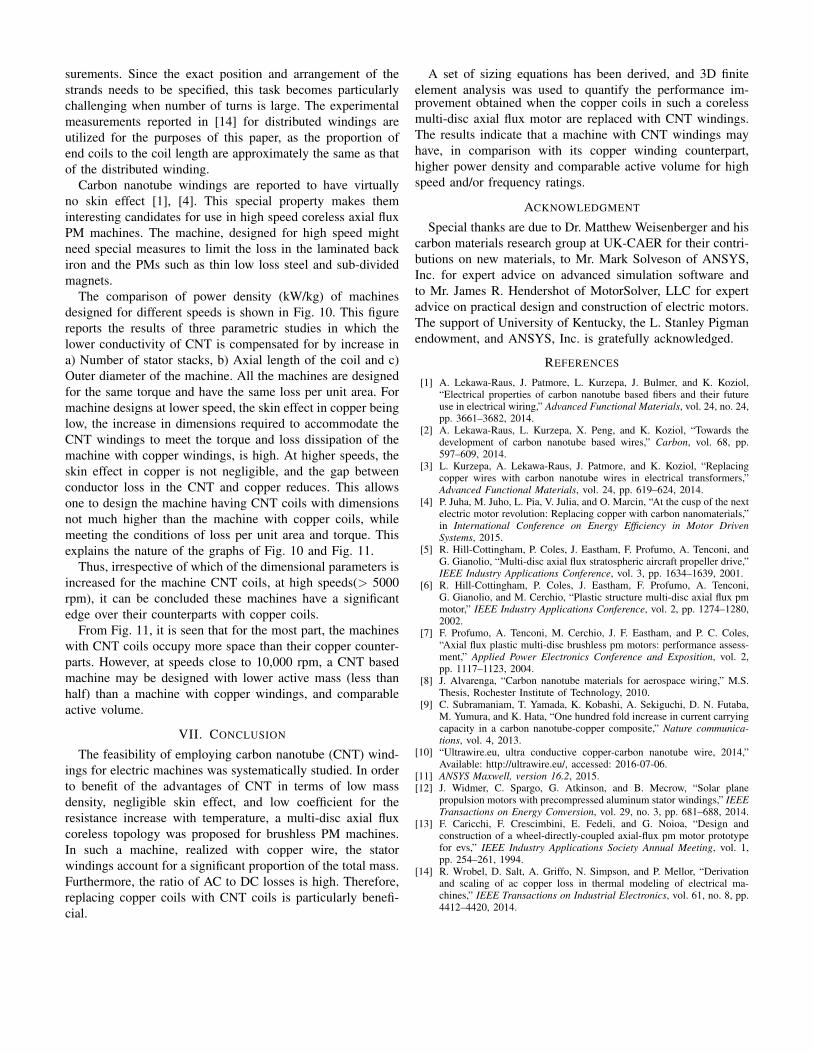
The comparison of power density (kW/kg) of machinesdesigned for different speeds is shown in Fig. 10. This figurereports the results of three parametric studies in which thelower conductivity of CNT is compensated for by increase ina) Number of stator stacks, b) Axial length of the coil and c)Outer diameter of the machine. All the machines are designedfor the same torque and have the same loss per unit area. Formachine designs at lower speed, the skin effect in copper beinglow, the increase in dimensions required to accommodate theCNT windings to meet the torque and loss dissipation of themachine with copper windings, is high. At higher speeds, theskin effect in copper is not negligible, and the gap betweenconductor loss in the CNT and copper reduces. This allowsone to design the machine having CNT coils with dimensionsnot much higher than the machine with copper coils, whilemeeting the conditions of loss per unit area and torque. Thisexplains the nature of the graphs of Fig. 10 and Fig. 11.
Thus, irrespective of which of the dimensional parameters isincreased for the machine CNT coils, at high speeds(> 5000rpm), it can be concluded these machines have a significantedge over their counterparts with copper coils.
From Fig. 11, it is seen that for the most part, the machineswith CNT coils occupy more space than their copper counter-parts. However, at speeds close to 10,000 rpm, a CNT basedmachine may be designed with lower active mass (less thanhalf) than a machine with copper windings, and comparableactive volume.
VII. CONCLUSION
The feasibility of employing carbon nanotube (CNT) wind-ings for electric machines was systematically studied. In orderto benefit of the advantages of CNT in terms of low massdensity, negligible skin effect, and low coefficient for theresistance increase with temperature, a multi-disc axial fluxcoreless topology was proposed for brushless PM machines.In such a machine, realized with copper wire, the statorwindings account for a significant proportion of the total mass.Furthermore, the ratio of AC to DC losses is high. Therefore,replacing copper coils with CNT coils is particularly benefi-cial.
A set of sizing equations has been derived, and 3D finiteelement analysis was used to quantify the performance im-provement obtained when the copper coils in such a corelessmulti-disc axial flux motor are replaced with CNT windings.The results indicate that a machine with CNT windings mayhave, in comparison with its copper winding counterpart,higher power density and comparable active volume for highspeed and/or frequency ratings.
ACKNOWLEDGMENT
Special thanks are due to Dr. Matthew Weisenberger and hiscarbon materials research group at UK-CAER for their contri-butions on new materials, to Mr. Mark Solveson of ANSYS,Inc. for expert advice on advanced simulation software andto Mr. James R. Hendershot of MotorSolver, LLC for expertadvice on practical design and construction of electric motors.The support of University of Kentucky, the L. Stanley Pigmanendowment, and ANSYS, Inc. is gratefully acknowledged.
REFERENCES
[1] A. Lekawa-Raus, J. Patmore, L. Kurzepa, J. Bulmer, and K. Koziol,“Electrical properties of carbon nanotube based fibers and their futureuse in electrical wiring,” Advanced Functional Materials, vol. 24, no. 24,pp. 3661–3682, 2014.
[2] A. Lekawa-Raus, L. Kurzepa, X. Peng, and K. Koziol, “Towards thedevelopment of carbon nanotube based wires,” Carbon, vol. 68, pp.597–609, 2014.
[3] L. Kurzepa, A. Lekawa-Raus, J. Patmore, and K. Koziol, “Replacingcopper wires with carbon nanotube wires in electrical transformers,”Advanced Functional Materials, vol. 24, pp. 619–624, 2014.
[4] P. Juha, M. Juho, L. Pia, V. Julia, and O. Marcin, “At the cusp of the nextelectric motor revolution: Replacing copper with carbon nanomaterials,”in International Conference on Energy Efficiency in Motor DrivenSystems, 2015.
[5] R. Hill-Cottingham, P. Coles, J. Eastham, F. Profumo, A. Tenconi, andG. Gianolio, “Multi-disc axial flux stratospheric aircraft propeller drive,”IEEE Industry Applications Conference, vol. 3, pp. 1634–1639, 2001.
[6] R. Hill-Cottingham, P. Coles, J. Eastham, F. Profumo, A. Tenconi,G. Gianolio, and M. Cerchio, “Plastic structure multi-disc axial flux pmmotor,” IEEE Industry Applications Conference, vol. 2, pp. 1274–1280,2002.
[7] F. Profumo, A. Tenconi, M. Cerchio, J. F. Eastham, and P. C. Coles,“Axial flux plastic multi-disc brushless pm motors: performance assess-ment,” Applied Power Electronics Conference and Exposition, vol. 2,pp. 1117–1123, 2004.
[8] J. Alvarenga, “Carbon nanotube materials for aerospace wiring,” M.S.Thesis, Rochester Institute of Technology, 2010.
[9] C. Subramaniam, T. Yamada, K. Kobashi, A. Sekiguchi, D. N. Futaba,M. Yumura, and K. Hata, “One hundred fold increase in current carryingcapacity in a carbon nanotube-copper composite,” Nature communica-tions, vol. 4, 2013.
[10] “Ultrawire.eu, ultra conductive copper-carbon nanotube wire, 2014,”Available: http://ultrawire.eu/, accessed: 2016-07-06.
[11] ANSYS Maxwell, version 16.2, 2015.[12] J. Widmer, C. Spargo, G. Atkinson, and B. Mecrow, “Solar plane
propulsion motors with precompressed aluminum stator windings,” IEEETransactions on Energy Conversion, vol. 29, no. 3, pp. 681–688, 2014.
[13] F. Caricchi, F. Crescimbini, E. Fedeli, and G. Noioa, “Design andconstruction of a wheel-directly-coupled axial-flux pm motor prototypefor evs,” IEEE Industry Applications Society Annual Meeting, vol. 1,pp. 254–261, 1994.
[14] R. Wrobel, D. Salt, A. Griffo, N. Simpson, and P. Mellor, “Derivationand scaling of ac copper loss in thermal modeling of electrical ma-chines,” IEEE Transactions on Industrial Electronics, vol. 61, no. 8, pp.4412–4420, 2014.