on the design of debond-resistant bimaterials: part i: free-edge singularity approach
TRANSCRIPT
On the design of debond-resistant bimaterialsPart I: Free-edge singularity approach
N.W. Klingbeil a, J.L. Beuthb,*aDepartment of Mechanical and Materials Engineering, Wright State University, 3640 Colonel Glenn Hwy., Dayton, OH 45435, USA
bDepartment of Mechanical Engineering, Carnegie Mellon University, 5000 Forbes Avenue, Pittsburgh, PA 15213-3890, USA
Received 04 May 1999; received in revised form 22 December 1999; accepted 05 January 2000
Abstract
Structures composed of bonded layers of dissimilar materials are common in a variety of applications. In manysuch structures, residual or applied stresses can lead to initiation of interface debonding near free edges. It is wellknown that the local elastic stress ®elds near the free edge of bonded dissimilar quarter planes can exhibit singular
behavior, with the order of the stress singularity determined by the material mismatch. A fracture mechanics-typeapproach to the design of debond-resistant bimaterials is adopted herein, which assumes that the local interfacetractions governing initiation of debonding can be completely described by the order of the stress singularity and a
suitably de®ned free-edge stress intensity factor. The global plane elasticity problem considered in this study is thatof a bimaterial strip composed of isotropic layers with a uniform edge pressure applied to the top layer, which is ageneral model of di�erential expansion. Finite element results are presented for dimensionless free-edge stress
intensity factors over a wide range of practical material mismatches and relative layer thicknesses. Trends in thedimensionless free-edge stress intensity factors are used to identify strategies for designing debond-resistantbimaterials. The results of this study motivate a comparison between free-edge singularity and interface crackapproaches to bimaterial design, which is the focus of Part II. 7 2000 Elsevier Science Ltd. All rights reserved.
Keywords: Debonding; Delamination; Free-edge singularity; Interface fracture; Failure assessment; Thin ®lms; Multi-layers
1. Introduction
Bonded layers of dissimilar materials are utilized in a variety of applications. For example, suchstructures are the product of a number of rapid prototyping and layered manufacturing processes. Onesuch application (and the primary motivation for this work) is Shape Deposition Manufacturing [1], in
Engineering Fracture Mechanics 66 (2000) 93±110
0013-7944/00/$ - see front matter 7 2000 Elsevier Science Ltd. All rights reserved.
PII: S0013-7944(00 )00002-3
www.elsevier.com/locate/engfracmech
* Correspondong author. Tel.: +1-412-268-3873; fax: +1-412-268-3348.
E-mail address: [email protected] (J.L. Beuth).

which three-dimensional parts are built up by successive molten material deposition and CNCmachining of each layer. Dissimilar bonded materials are also applied extensively in microelectronicdevices, particularly in the area of data storage and processing. Bonded layers are used in theconstruction of integrated circuit devices, and they occur as thin ®lm/substrate combinations in magnetictapes and hard disk drives. Dissimilar bonded materials also exist in welding, soldering and protectivecoating applications. A number of these and other applications for bonded ®lms and multilayers arediscussed in the review paper by Evans and Hutchinson [2].
It is typical in the above applications that dissimilar bonded materials are subject to di�erentialexpansion stresses, which can lead to initiation of interface debonding near free edges. Initiation ofdebonding is undesirable for multiple reasons. Debonded edges can have serious implications on thestructural reliability of bimaterial systems and may lead to interface crack extension or completedelamination. Such debonding can prevent thin ®lms or coatings from ful®lling their desired purposes.In layered manufacturing applications, debonded edges can a�ect part dimensional tolerances andsurface roughness. Residual stress-driven interface crack extension in multilayers has been considered byBeuth and Narayan [3] and Narayan and Beuth [4]. The focus of this paper is the associated problem ofinitiation of debonding at free edges, with the goal of providing strategies for designing debond-resistantbimaterial layers.
The approach taken herein employs the classical elasticity model of perfectly bonded dissimilar elasticquarter planes, for which the local interface tractions near the free edge generally exhibit singularbehavior [5±7]. In this study, a fracture mechanics type of approach is adopted in characterizing theintensity of the free-edge stress singularity governing initiation of interface debonding for a generalbimaterial problem con®guration. The global problem considered is that of a bimaterial strip with auniform edge pressure applied to the top layer (see Fig. 1), which is a general model of di�erentialexpansion. In addition to residual or thermal stresses in layered manufacturing, the problem consideredcan be used in modeling a variety of global loadings which would result in uniform relative expansionsor contractions of the otherwise unbonded layers.
Bimaterial layers under di�erential expansion have been the subject of numerous studies in theliterature. Perhaps the earliest investigation was by Timoshenko [8], who in a study of bi-metalthermostats used a strength of materials approach to obtain a far-®eld beam-theory solution valid awayfrom the free edges. Timoshenko's solution was extended by Hess [9], who utilized an eigenfunctionexpansion procedure to investigate the interface stresses near the free edges. Similar results wereobtained by Agarwal and Huggins [10] using the ®nite element method. The primary drawback of suchstress-based approaches is their inability to characterize singular behavior in the interface stresses.Singularity parameters for a variety of bimaterial joint con®gurations under thermal loading have morerecently been investigated by several researchers [11±15]. The goal of the current paper is to map outtrends in free-edge stress intensity factors for bimaterial layers under di�erential expansion in a fashionsu�ciently general and comprehensive for bimaterial design.
A number of researchers have investigated the use of free-edge stress intensity factors for experimentalcharacterization of interface debonding. The use of singularity parameters as failure criteria for bondedjoints was ®rst suggested by Gradin [16]. Free-edge stress intensity factors have been investigated byOkajima [17], Reedy [18] and Akisanya [19] for characterizing failure in adhesive butt joints, and byHattori et al. [12] to characterize free-edge debonding in plastic-encapsulated integrated circuit devices.Although the results of this study could potentially be useful in the context of a failure criterion, theprimary goal of this work is to identify trends in free-edge stress intensity factors for use in bimaterialdesign.
Traction separation laws such as that introduced by Tvergaard and Hutchinson [20,21] have recentlybeen applied to the modeling of both crack propagation and free-edge crack initiation problems inbonded layers. Although ®tting of these laws to characterize resistance to interfacial fracture can be
N.W. Klingbeil, J.L. Beuth / Engineering Fracture Mechanics 66 (2000) 93±11094
di�cult, recent work by Liechti and co-workers [22,23] and others suggests that this approach o�ers thepotential of unifying the consideration of crack initiation and propagation problems. Trends in resultsidenti®ed herein and in Part II of this paper [24] can be compared directly with trends predicted bytraction separation fracture models currently under development.
In this study, dimensionless free-edge stress intensity factors are extracted from ®nite element modelsfor the con®guration of Fig. 1 over a wide range of practical material combinations and relative layerthicknesses. Results are summarized in the form of four plots, which can be utilized by designers ofbimaterial systems. The numerical results are used to provide guidelines for the design of debond-resistant bimaterials, where the likelihood of free-edge debonding is reduced. As demonstrated in Part IIof this paper [24], the results of this work suggest that conclusions based on free-edge debonding are notalways in keeping with those based on well-known steady-state interface crack models, so that bothinitiation of debonding at free edges and subsequent interface cracking should be considered inbimaterial design.
2. Global problem description
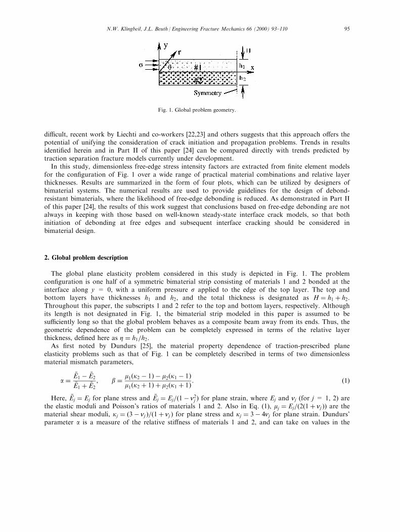
The global plane elasticity problem considered in this study is depicted in Fig. 1. The problemcon®guration is one half of a symmetric bimaterial strip consisting of materials 1 and 2 bonded at theinterface along y = 0, with a uniform pressure s applied to the edge of the top layer. The top andbottom layers have thicknesses h1 and h2, and the total thickness is designated as H � h1 � h2:Throughout this paper, the subscripts 1 and 2 refer to the top and bottom layers, respectively. Althoughits length is not designated in Fig. 1, the bimaterial strip modeled in this paper is assumed to besu�ciently long so that the global problem behaves as a composite beam away from its ends. Thus, thegeometric dependence of the problem can be completely expressed in terms of the relative layerthickness, de®ned here as Z � h1=h2:
As ®rst noted by Dundurs [25], the material property dependence of traction-prescribed planeelasticity problems such as that of Fig. 1 can be completely described in terms of two dimensionlessmaterial mismatch parameters,
a ��E1 ÿ �E2
�E1 � �E2
, b � m1�k2 ÿ 1� ÿ m2�k1 ÿ 1�m1�k2 � 1� � m2�k1 � 1� : �1�
Here, �Ej � Ej for plane stress and �Ej � Ej=�1ÿ n2j � for plane strain, where Ej and nj (for j = 1, 2) arethe elastic moduli and Poisson's ratios of materials 1 and 2. Also in Eq. (1), mj � Ej=�2�1� nj �� are thematerial shear moduli, kj � �3ÿ nj �=�1� nj � for plane stress and kj � 3ÿ 4nj for plane strain. Dundurs'parameter a is a measure of the relative sti�ness of materials 1 and 2, and can take on values in the
Fig. 1. Global problem geometry.
N.W. Klingbeil, J.L. Beuth / Engineering Fracture Mechanics 66 (2000) 93±110 95

range ÿ1 < a < 1: As discussed by Suga et al. [26], values of b for practical material combinationsgenerally lie in the range 0RbRa=4, with b � a=4 corresponding to n1 � n2 � 1=3 in plane strain.Interchanging materials 1 and 2 changes the sign of both a and b, and a � b � 0 for the case of nomaterial mismatch. With the introduction of Dundurs' parameters, the problem of Fig. 1 can becompletely described by the three dimensionless parameters a, b and Z:
The problem of Fig. 1 is su�ciently general to account for a variety of global loadings which wouldresult in uniform expansions or contractions of the otherwise unbonded layers, as long as the local free-edge ®elds can be modeled in plane stress or plane strain. As detailed in Appendix A, such loadings canbe readily expressed in terms of an equivalent edge load s applied to the top layer. The equivalent edgeload s is calculated according to the global problem behavior, which may be plane stress or planestrain, or may result from a loading condition which is neither plane stress nor plane strain. In modelinga physical application using the results of this work, the global loading condition is re¯ected in theequivalent edge load s, while the local plane stress or plane strain condition determines Dundurs'parameters a and b for comparison with the plane elasticity problem of Fig. 1.
As a means of illustration, several global problem geometries and corresponding equivalent edge loadsare depicted in Fig. 2. In all cases, a positive value of s corresponds to the compressive edge loading ofFig. 1. As a ®rst example, the problem of Fig. 1 precisely models the free-edge singularity for abimaterial strip under global plane stress or plane strain, with uniform thermal loadings DTj applied toeither or both layers (Fig. 2(a)). The equivalent edge load s is given by
Fig. 2. Several global problems and corresponding equivalent edge loads for the problem of Fig. 1.
N.W. Klingbeil, J.L. Beuth / Engineering Fracture Mechanics 66 (2000) 93±11096

s � ÿ �E1��a1DT1 ÿ �a2DT2�, �2�where �aj � aj for plane stress and �aj � �1� nj �aj for plane strain. Here, aj are the coe�cients of thermalexpansion of materials 1 and 2 (not to be confused with Dundurs' parameter a). Note that theequivalent edge load s for the classical problem of a bimaterial strip under a uniform thermal loadingDT < 0 is obtained by simply setting DT1 � DT2 � DT in Eq. (2).
For a wide class of material mismatches, the plane problem of Fig. 1 can also be used in modeling thelocal interface tractions in a rectangular bimaterial plate (Fig. 2(b)), for which uniform thermal loadingsresult in a far-®eld state of equal biaxial stress. In this case, the global biaxial loading condition resultsin an equivalent edge load s given by
s � ÿ E1
1ÿ n1�a1DT1 ÿ a2DT2�, �3�
which is applied to both the x- and z-faces. For materials having equal Poisson's ratios, the resultingfree-edge ®elds can be modeled by the plane elasticity problem of Fig. 1. In the event of unequalPoisson's ratios, the uniform edge load s applied along the x-face would result in an additionalcontribution to the edge singularity along the z-face, and vice-versa. Such a contribution cannot bemodeled by the problem of Fig. 1. Provided n1 � n2, however, the free-edge ®elds along both the x- andz-faces (away from the corners) can be modeled in plane strain, with the equivalent edge load s given byEq. (3). Furthermore, the interface singularity at the plate corner �x � z � 0 in Fig. 2(b)) can simply bemodeled as a superposition of global plane stress problems in the x±y and y±z planes, which can beseparately modeled by the problem of Fig. 1.
Provided n1 � n2, the problem of Fig. 1 is also applicable to cylindrical (axisymmetric) bimaterialplates under uniform thermal loadings (Fig. 2(c)). For axisymmetric bimaterials of su�ciently largeradii, the local free-edge ®elds can be modeled in plane strain (see Ref. [18], for example). As for thecase of a rectangular plate, the cylindrical plate is subject to a state of far-®eld biaxial loading, so thatthe equivalent edge load s is obtained from Eq. (3).
Finally, the problem of Fig. 1 can be applied to a bimaterial plate under a uniform out-of-planeextension ezz (Fig. 2(d)). If n1 6�n2, the individual layers will experience di�erential contractions in the x-direction. The resulting x-face free-edge problem can be modeled by the problem of Fig. 1, where thelocal free-edge ®elds are modeled in plane strain. The equivalent edge load s is given by
s � E1
1ÿ n21�n1 ÿ n2�ezz: �4�
3. Local free-edge ®elds
In order to characterize the interface tractions governing initiation of free-edge debonding, it is ®rstnecessary to summarize the nature of the local stress ®elds obtained in the context of plane elasticity viaasymptotic analysis. The asymptotic geometry, boundary conditions and interface matching conditionsfor the problem of Fig. 1 are depicted in Fig. 3. The materials are modeled as perfectly bonded, so thatboth the tractions and displacements are continuous across the interface. The superscripts 1 and 2 in thematching conditions of Fig. 3. denote materials 1 and 2, respectively.
The asymptotic analysis for perfectly bonded dissimilar elastic quarter planes subjected to tractionswas ®rst conducted by Bogy [5], and was later expressed in terms of Dundurs' parameters a and b byBogy [6]. The analysis was extended to wedges of arbitrary angle by Bogy [7] and Hein and Erdogan
N.W. Klingbeil, J.L. Beuth / Engineering Fracture Mechanics 66 (2000) 93±110 97

[27]. An asymptotic analysis for bonded quarter planes in the presence of a uniform thermal loading DThas more recently been conducted by Suga et al. [11], who used a complex variable approach with thethermal e�ects incorporated directly into the strain-displacement relations. The analysis for thermalloading has also been summarized by Munz and Yang [13], among others.
As discussed by Bogy [6], a power-type stress singularity can exist near the vertex of dissimilar bondedquarter planes for material combinations satisfying a�aÿ 2b� > 0, which is the case for all materialcombinations considered herein. In the presence of a power-type singularity, the local free-edge stress®elds (as r40� take the form
sij � Krlÿ1fij�y� �O�r0�: �5�
For values of l < 1, the quantity jlÿ 1j is the power of the stress singularity. The eigenvalue l dependson the material mismatch parameters a and b, and satis®es the transcendental equation
f�l� � l2ÿl2 ÿ 1
�a2 � 2l2
�sin2 lp
2ÿ l2
�ab�
�sin2 lp
2ÿ l2
�2
b2 � 14sin2�lp� � 0 �6�
The left-hand side of Eq. (6) is plotted in Fig. 4 for various values of a and with b � a=4: For nonzerovalues of a, the characteristic equation has one root with l < 1 and one root at l � 1: For the case ofa � 0, there is a double root at l � 1: The roots with l < 1 correspond to singular behavior, and thepower of the stress singularity is seen to increase with jaj: The roots at l � 1 correspond to regularterms of O�r0� in the local stress ®elds.
Also in Eq. (5), K is the free-edge stress intensity factor, which is de®ned here in terms of the interfacenormal stress as
K � limr40
syy�y � 0�rlÿ1
: �7�
The above de®nition of K corresponds to a normalization of the angular functions fij�y� such thatfyy�y � 0� � 1 [13], in which case the local interface tractions (along y � 0� take the form
syy � Krlÿ1 � s0 �8�
Fig. 3. Asymptotic geometry, boundary conditions and interface matching conditions.
N.W. Klingbeil, J.L. Beuth / Engineering Fracture Mechanics 66 (2000) 93±11098

and
sry � Krlÿ1fry�y � 0�: �9�
While the eigenvalue l, the angular functions fij�y� and the regular term s0 can all be determined byasymptotic analysis, the free-edge stress intensity factor K depends on the global loading and problemgeometry. Note from Eqs. (8) and (9) that both the local interface shear and normal tractions aregoverned by a single stress intensity factor K, which is in contrast to the near-crack-tip ®eldsencountered in classical and interfacial fracture mechanics. The presence of the regular term s0 in Eq.(8) is necessary for satisfaction of the nonhomogenous boundary condition syy�r, y � p=2� � ÿs: Theangular functions fij�y� are dimensionless functions of the elastic material mismatch, and are given forthe case of traction-free edges by Okajima [17], among others. As discussed by Yang and Munz [15], theangular functions fij�y� are unchanged by a nonhomogeneous boundary condition at the free edge (e.g.,an applied edge load s).
The regular term s0 for the edge loading of Fig. 3 is obtained here from results available in theliterature for the case of a uniform thermal loading (see, for example, Refs. [11,13,28]). As discussed bySuga et al. [11], the regular term s0 in the presence of a uniform thermal loading DT can be written as
s0 � DEDaDT, �10�
where
DE � 8m1m2m1�k2 ÿ 3� ÿ m2�k1 ÿ 3� �11�
and Da � �a1 ÿ �a2: In light of the equivalence between the thermal and edge load problems (see Eq. (2)),the regular term for the problem of Fig. 1 is given by
Fig. 4. Characteristic equation plotted for several values of a and with b � a=4:
N.W. Klingbeil, J.L. Beuth / Engineering Fracture Mechanics 66 (2000) 93±110 99

s0 � ÿDEs�E1
: �12�
The regular term s0 is retained in Eq. (8) because inspection of Eqs. (11) and (12) reveals thatjs0j41 as the material mismatch approaches zero (i.e., as a40 and b40). Thus, for cases of mildelastic mismatch, s0 can be signi®cant even very close to the free edge. In determining K using ®niteelements, an overly re®ned mesh can be avoided by separating the analytically calculated term s0 fromthe numerical results [11,13]. As discussed by Munz et al. [28], it should also be noted that js0j41 forall material combinations exhibiting power-type singularities where jlÿ 1j40: In addition to materialcombinations where a40 and b40, this also includes material combinations where b4a=2, for whichthe power-type singularity gives way to a logarithmic singularity. However, such material combinationsare rarely found in practice, and are not considered further herein.
Because s041 as the material mismatch approaches zero, s0 can be an important contribution tothe interface normal stress distribution for cases of weak material mismatch. However, because theregular term s0 depends only on the material mismatch, the e�ects on the local interface tractions ofchanges in global problem geometry are completely determined by trends in K. Thus, an approach basedsolely on K is appropriate for comparing prospective geometries of the same material mismatch (as donein the results section of this paper). It should ®nally be noted that since they include s0, the localinterface tractions of Eqs. (8) and (9) are dominant over a region in the vicinity of the bimaterial vertexwhich is of roughly the same order as the region of K-dominance observed in interfacial fracturemechanics (e.g., ÿ3:5 < log�r=h� < ÿ2:5, where h � min�h1, h2�). Furthermore, within this region of K-dominance, the sign of the local interface normal stress for all the material combinations consideredherein has been found to be the same as the sign of K. This is true despite the fact that the sign of K isgenerally not equal to the sign of s0: This being said, care should be taken in applying the resultspresented in this paper to bimaterial interfaces with milder elastic mismatches than those consideredherein, for which the relative importance of the regular term s0 may invalidate conclusions based solelyon K.
4. Numerical modeling procedures
As de®ned in Eq. (7), the free-edge stress intensity factor K has units of stress x�length�1ÿl: In order todetermine su�ciently general numerical results, is useful to de®ne a dimensionless free-edge stressintensity factor K � in terms of the applied edge load s and the total bimaterial strip thickness H. Tothis end, Eq. (8) can be rewritten as
s� � K ��r=H�lÿ1, �13�where
s� � syy�y � 0� ÿ s0s
�14�
and
K � � KH lÿ1
s: �15�
For the con®guration of Fig. 1, K � depends on the material mismatch parameters and the relativelayer thickness, so that K � � K ��a, b, Z�: In order to completely characterize K �, it is necessary to
N.W. Klingbeil, J.L. Beuth / Engineering Fracture Mechanics 66 (2000) 93±110100

determine results for both positive and negative values of a and b, as well as for values of Z < 1 andZr1: However, it can be shown by superposition that
K �� ÿ a, ÿ b, 1=Z� � ÿ�1� a1ÿ a
�K ��a, b, Z�: �16�
The above relation allows the complete range of results to be generated by considering both positive andnegative values of a and b over only half the range of Z, or by considering only positive or negativevalues of a and b over the complete range of Z: In this study, the former approach has been employedin generating the numerical results, while the latter approach has proven more convenient for presentingthe results.
In applying the results of this work to thin ®lms or coatings, it may also be convenient to normalizeK with respect to the thickness of the relatively thin layer. Without loss of generality, it may be assumedthat the relatively thin layer is the top layer in Fig. 1. Results for K normalized with respect to the toplayer thickness h1 can be obtained using the relation
Khlÿ11
s��1� 1
Z
�1ÿlK �: �17�
Finite element calculations have been conducted for the con®guration of Fig. 1 over a wide range ofmaterial mismatches and relative layer thicknesses using the software package ANSYS. All results havebeen obtained using four-noded bi-linear continuum elements in plane strain. The ®nite element runshave been conducted for values of Zr1, and results for Z < 1 have been determined by Eq. (16). Resultshave been generated over a wide range of a, for both b � a=4 and b � 0:
Fig. 5. (a) Far-®eld and (b) Near-edge ®nite element meshes.
N.W. Klingbeil, J.L. Beuth / Engineering Fracture Mechanics 66 (2000) 93±110 101

Example far-®eld and near-edge ®nite element meshes are shown in Fig. 5 for the case of Z � 1: Thenear-edge mesh consists of 48 rings of 16 elements biased towards the bimaterial vertex. For all valuesof Z, the near-edge mesh has extended through half the thickness of the bottom layer. Data forincreasing values of Z have been obtained by successively doubling the top layer thickness h1 andincreasing the length of the far-®eld mesh. This has been accomplished by adding elements to the far-®eld mesh of Fig. 5 while conserving its overall 5:1 aspect ratio (which in view of the symmetrycondition corresponds to composite strips having an aspect ratio of 10:1). Because the free-edge e�ectsgive way to the far-®eld beam theory solution at a distance from the ends on the order of the totalthickness H, the numerical results presented in the next section are applicable to arbitrarily longbimaterials.
The procedure for extracting the free-edge stress intensity factor from the ®nite element results followsthat of Suga et al. [11] and Munz and Yang [13]. After rearranging and taking the logarithm of both
Fig. 6. Least square ®t of interface normal stress for a � ÿ0:90, b � a=4 and h � 1:
Table 1
The eigenvalue l for selected values of a, with b � a=4 and b � 0
Value of a Solution to Eq. (6) Finite element results
b � a=4 b � 0 b � a=4 b � 0
20:30 0.9653 0.9371 0.9661 0.9382
20:50 0.9099 0.8532 0.9108 0.8539
20:70 0.8354 0.7564 0.8358 0.7575
20:90 0.7434 0.6510 0.7434 0.6539
N.W. Klingbeil, J.L. Beuth / Engineering Fracture Mechanics 66 (2000) 93±110102

sides, Eq. (13) can be written as
log
��r
H
�s��� log�K �� � llog
�r
H
�: �18�
Here, s� is determined according to Eq. (14) by separating the regular term s0 (calculated using Eq.(12)) from the numerical results for the interface normal stress syy�y � 0� in the vicinity of the bimaterialvertex. The numerical results for syy�y � 0� for all cases considered in this study have been extractedfrom nine elements along the bimaterial interface, in the range ÿ3:5 < log� rh2 � < ÿ2:5:
Eq. (18) suggests that K � can be determined from a linear least square curve ®t of log��r=H �s�� vs.log�r=H �: A representative plot is shown in Fig. 6 for the case of Z � 1, with a � ÿ0:90 and b � a=4: InFig. 6, the excellent representation of the plotted numerical data by the linear least square ®t isrepresentative of all cases considered herein. Inspection of Eq. (18) reveals that the slope of the plotgives the eigenvalue l, while K � is determined from the ordinate intercept. The eigenvalue l is knownfrom the roots to Eq. (6), and serves as a check on the ®nite element results. The accuracy of the ®niteelement results in determining l for the case of Z � 1 is illustrated in Table 1 for several values of a, for
Fig. 7. Dimensionless K for various values of a, with b � a=4 and b � 0:
N.W. Klingbeil, J.L. Beuth / Engineering Fracture Mechanics 66 (2000) 93±110 103

both b � a=4 and b � 0: As seen in the table, the ®nite element results for l are for all cases within0.5% of the solution to Eq. (6).
5. Results and discussion
For the con®guration of Fig. 1, numerical results for both K � and Khlÿ11 =s are plotted in Fig. 7 as afunction of the relative layer thickness Z: The abscissas in Fig. 7 actually represent values of log2�Z�, butare labeled in terms of Z for convenience. Results are presented for several values of a, for both b � a=4and b � 0: In the interest of brevity, results are plotted in Fig. 7 only for negative values of a (for whichthe top layer is relatively compliant). K � results for positive values of a can be determined from the K �
curves in Fig. 7 using Eq. (16), after which corresponding results for Khlÿ11 =s can be generated usingEq. (17). Note that application of Eq. (16) is equivalent to ¯ipping the K � curves about the lines Z � 1and K � � 0 and rescaling the ordinates. It is important to note that because the order of the stresssingularity depends on the material mismatch, a direct comparison of K � results for di�erent materialmismatches is ambiguous. This is especially true since the ordinate scales in the plots of Fig. 7 indicatethat jK �j increases as jaj (and thus the power of the singularity) decreases. However, the plots of Fig. 7are highly useful in illustrating how the e�ects on the free-edge singularity of changes in global problemgeometry vary with the material mismatch.
An interesting trend in the K � curves can be observed in Fig. 7. For each value of a, K � has anabsolute maximum at a particular value of Z: Furthermore, the locations of these maxima depend on a,and are independent of whether b � a=4 or b � 0: For example, the peaks for a � ÿ0:30 occur betweenZ � 1=4 and Z � 1=2, while the peaks for a � ÿ0:90 occur for Z11: The locations of the peaks appearto move monotonically with increasing jaj: For the negative values of a considered, all the peaks occurfor values of Z < 1: In light of Eq. (16), the peaks for positive values of a occur for values of Z > 1:
It is clear from the plots in Fig. 7 that for each value of a, the trends in K � are essentially the samefor b � a=4 and b � 0: However, inspection of the ordinate scales reveals that for each value of a, themagnitude of K � is substantially larger for b � a=4 than for b � 0: These results might be expectedbased on the work of Bogy [6], who showed that the fraction of an applied edge loading transmittedbetween dissimilar bonded quarter planes is independent of b: Thus, if the free-edge stress singularity isexcited to the extent that it participates in transmitting the interface loads, and if the interface loadsdepend only on a, then the trends in K � should be independent of b: Furthermore, the power of thestress singularity is smaller for b � a=4 than for b � 0: Because the loads transmitted are the same ineach case, it seems reasonable that the magnitude of K � is larger for b � a=4 than for b � 0: Thein¯uence of the global interface loads on the participation of the singular ®elds is discussed further inPart II [24].
As seen in Fig. 7, the trends in Khlÿ11 =s illustrate the transition from a bimaterial strip to that of athin ®lm/substrate combination. Thin ®lm limits are observed for small values of Z, in which case thefree-edge stress intensity factor K depends only on h1: The Khlÿ11 =s curves merge with the K � curves forlarge values of Z, which must be the case as h14H: The transition to thin ®lm behavior becomesincreasingly rapid as the relative compliance of the top layer increases (i.e., as a becomes more negative).Thin ®lm limits can also be observed for positive values of a, although the transition to thin ®lmbehavior becomes less rapid as the top layer becomes relatively sti� (i.e., as a increases). See, forexample, the results for a particular material combination with a > 0 plotted in Ref. [14] for the case ofthermal loading.
As previously mentioned, inspection of the ordinate scales in Fig. 7 reveals that the magnitude of thefree-edge stress intensity factor increases with decreasing material mismatch (decreasing jaj ). This resultcan be expected based on results in the literature for bonded joints under thermal loading. While the
N.W. Klingbeil, J.L. Beuth / Engineering Fracture Mechanics 66 (2000) 93±110104

regular term s0 becomes in®nite in the absence of a material mismatch, the free-edge stress intensityfactor has been shown by Munz and Yang [13], among others, to also become in®nite but with oppositesign. This result can be explained by considering the limiting case of no material mismatch. As a40and b40, the power of the singularity jlÿ 1j40 and the local stress ®elds must approach that for a �b � 0: In the absence of a material mismatch, however, there is no singularity, so that
limr40
syy�y � 0� � KTs: �19�
Here, KT is a stress concentration factor de®ned for the case of a � b � 0 in terms of the applied edgeload s: Thus, while approaching in®nity with opposite signs, K and s0 combine as a40 and b40 sothat Krlÿ1� s04KTs: As discussed by Munz et al. [28], a similar transition must also occur for othermaterial combinations where jlÿ 1j40 (e.g., material combinations where b4a=2:).
The stress concentration factor KT has been extracted from numerical results for a � b � 0 and isplotted in Fig. 8 as a function of the relative layer thickness Z: It should be noted that the term `stressconcentration factor' is somewhat of a misnomer, since the maximum interface normal stress for a �b � 0 is for all cases less than the applied edge load s: As seen in Fig. 8, the interface normal stress istensile for Z < 1, zero for Z � 1 and compressive for Z > 1, which agrees with the results of Hess [9].Because the regular term s0 is independent of Z, the Z-dependence of KT results entirely from the Z-dependence of K � as a40: In fact, inspection of Fig. 7 reveals that trends in K � become increasinglysimilar to trends in KT as jaj decreases. As opposed to the stress concentration factor KT, however, theresults of Fig. 7 suggest that the sign of K � is ®xed by the material mismatch. This is in keeping withresults presented in the literature for thermal loading (see Refs. [13,14]).
The fact that the sign of K � is ®xed by the material mismatch follows from the fact that both thesingular interface normal and shear stresses are governed by only a single stress intensity factor K (seeEqs. (8) and (9)). As might be expected, the singular interface shear stress sry�y � 0� for all materialcombinations considered herein acts in the direction opposing the applied edge load, regardless of the
Fig. 8. Stress concentration factor KT for a � b � 0:
N.W. Klingbeil, J.L. Beuth / Engineering Fracture Mechanics 66 (2000) 93±110 105

global problem geometry. Thus, for the problem of Fig. 1, the sign of the singular interface shear stressis essentially prescribed by the applied edge load s: According to Eq. (9), however, the sign of sry�y � 0�depends not only by the sign of K, but also on the sign of the quantity fry�y � 0�: Moreover, the sign ofthe quantity fry�y � 0� can be shown by either global superposition or local asymptotic analysis toswitch with a reversal of the material mismatch (i.e., a switch in sign of a and b ). Thus, if the singularinterface shear stress is to oppose the applied edge load, the sign of K must also change with the sign ofa and b: As a result, the sign of the interface normal stress (i.e., the sign of K �� is ®xed by the materialmismatch and thus independent of the global problem geometry.
6. Design implications
The results of the previous section can be used in the design of debond-resistant bimaterials. Here,`debond-resistant' denotes a bimaterial design for which a positive value of the free-edge stress intensityfactor K is either reduced or made negative. For negative values of K, the singular interface normalstress is compressive, which renders initiation of debonding less likely. The conclusions drawn here arebased on results for the material combinations considered in the previous section, which arerepresentative values covering a wide range of practical material mismatch parameters. The generalguidelines outlined below can also be expected to apply for other material combinations exhibitingpower-type stress singularities.
If a designer has freedom in choosing the materials for a given application, it is desirable to choosematerials for which K is negative. In Fig. 7, the K � results presented for negative values of a arepositive. It follows from Eq. (16) that the corresponding K � results for positive values of a are negative.In light of the thin ®lm limits, this result holds for arbitrary values of Z: Thus, in designing a bimaterialin which the top layer experiences a relative contraction (in a thin ®lm or coating application, forexample), it is advantageous to use a bottom layer made of material which is comparatively compliant.Obviously, the opposite is true if the top layer experiences a relative expansion.
In the event that the required material combination for a given application results in a positive valueof K, the results of Fig. 7 suggest how K can be reduced by choosing an appropriate relative layerthickness Z: For bimaterials of a given total thickness H, the peaks in K� represent worst case designscenarios. In many cases the value of K � can be substantially reduced by adjusting the relative layerthickness, especially in the case of large jaj: For a � ÿ0:90 and b � a=4 for example, the worst casedesign is to have layers of roughly equal thickness, while a design with Z � 32 results in a reduction ofK � by nearly 50%. In general, the magnitude of K � can be most substantially reduced if one layer ismade relatively thin.
Finally, in applying the results of this work, the designer should be reminded that the results of Fig. 7are strictly applicable only for physical situations in which the free-edge singularity is dominant. Inaddition to a material mismatch at least as strong as those considered herein, this requires that the edgegeometry closely resembles that of Fig. 3 (i.e., perfectly bonded quarter planes). Indeed, a commoncriticism of the free-edge singularity approach is that initiation of debonding at free-edges often occursat defects or voids, or that local variations in the actual edge geometry may overwhelm the e�ects of thefree-edge singularity. Although such criticisms merit careful consideration in adopting a free-edgesingularity approach to failure prediction, they are of far less consequence in applying qualitative designguidelines such as those discussed in this section.
N.W. Klingbeil, J.L. Beuth / Engineering Fracture Mechanics 66 (2000) 93±110106

7. Summary
In this study, the plane elasticity problem of a bimaterial strip with a uniform edge load applied tothe top layer has been considered for use in the design of debond-resistant bimaterial systems. Inaddition to applied edge loadings, the problem considered is su�ciently general that it can be used inmodeling a variety of loadings where the individual layers experience uniform di�erential expansions orcontractions, as long as the local free-edge ®elds can be modeled in plane stress or plane strain. Finiteelement results for dimensionless free-edge stress intensity factors governing initiation of debonding havebeen summarized in four plots covering a wide range of practical material mismatches and relative layerthicknesses. Trends in the free-edge stress intensity factors have been used to identify design strategiesfor which the likelihood of debonding is reduced. Namely, because the sign of the singular interfacenormal stress is ®xed by the material mismatch, it is possible to choose materials such that the interfacenormal stress at the free-edge is compressive. In the event that the required materials preclude such achoice, the magnitude of the free-edge stress intensity factor can often be substantially reduced byadjusting the relative layer thickness. Finally, the results of this work warrant a comparison of the free-edge singularity and interface crack approaches to bimaterial design, which is the focus of Part II [24].
Acknowledgements
This work has been supported by the National Science Foundation under grants EID-9256665 andDMI-9700320, and the Carnegie Mellon University, Department of Mechanical Engineering.
Appendix A
Uniform di�erential expansions or contractions of bimaterial layers can be expressed in terms of
Fig. A1. Uniform di�erential contraction in terms of edge loadings.
N.W. Klingbeil, J.L. Beuth / Engineering Fracture Mechanics 66 (2000) 93±110 107

equivalent uniform edge loadings via a `cut and paste' procedure (see, for example, Suo and Hutchinson[29]). The uniform di�erential contractions of materials 1 and 2 (such as those due to a uniformtemperature change DT < 0� are illustrated in Fig. A1. The individual layers are ®rst allowed to contractindependently (Fig. A1(a)), and are then stretched back to their original lengths under uniform tensileloads s1 and s2 (Fig. A1(b)). The edge loads s1 and s2 are related to the uniform contractions E1 and E2as
s1 � ~E1e1, s2 � ~E2e2: �A1�
Here, ~Ej are e�ective moduli of the two materials, which in the case of global plane stress or planestrain are simply given by ~Ej � �Ej: However, Eq. (A1) may also be applied for certain global loadingconditions which are neither plane stress nor plane strain, in which case ~Ej 6� �Ej: For example, in the caseof a bimaterial plate subject to biaxial contractions, ~Ej � Ej=�1ÿ n�: Finally, while still stretched to theiroriginal lengths, the layers are bonded together and the tensile stresses at the free edges are released byapplication of the compressive edge loadings s1 and s2 (Fig. A1(c)). Thus, the interface tractionscorresponding to a uniform di�erential contraction are given exactly by the problem of Fig. A1(c), whilethe complete solution is obtained by superposition of the uniform tensile stresses sxx � s1 and sxx � s2in materials 1 and 2 (Fig. A1(b)).
Consider now the problem of Fig. A2(a), in which edge loads s1 and s2 are applied to each layer. It
Fig. A2. Conversion from two edge loads to a single equivalent edge load.
N.W. Klingbeil, J.L. Beuth / Engineering Fracture Mechanics 66 (2000) 93±110108

is possible to express such a loading in terms of an equivalent edge load s applied to the top layer (i.e.,the problem of Fig. 1). This is accomplished by superposing the trivial loading of Fig. A2(b), in whichno strain mismatch occurs at the interface, so that all interface tractions are zero. Thus, with respect tothe interface tractions, the problem of Fig. A2(a) is equivalent to the problem in Fig. A2(c), where thesingle equivalent edge load s is given by
s � s1 ÿÿ
~E1= ~E2
�s2: �A2�
References
[1] Merz R, Prinz FB, Ramaswami K, Terk M, Weiss LE. Shape deposition manufacturing. In: Proc. Solid Freeform Fabrication
Symposium, Marcus H, Beaman JJ, Barlow JW, Bourell KL, Crawford RH, editors. The University of Texas, Austin, August,
1±8, 1994.
[2] Evans AG, Hutchinson JW. The thermomechanical integrity of thin ®lms and multilayers. Acta Metallurgica et Materiala
1995;43(7):2507±30.
[3] Beuth JL, Narayan SH. Residual stress-driven delamination in deposited multi-layers. International Journal of Solids and
Structures 1996;33(1):65±78.
[4] Narayan SH, Beuth JL. Axisymmetric delamination in deposited multi-layers. International Journal of Solids and Structures
1997;34:4617±31.
[5] Bogy DB. Edge-bonded dissimilar orthogonal elastic wedges under normal and shear loading. Journal of Applied Mechanics
1968;35:460±6.
[6] Bogy DB. On the problem of edge-bonded elastic quarter-planes loaded at the boundary. International Journal of Solids and
Structures 1970;6:1287±313.
[7] Bogy DB. Two edge-bonded elastic wedges of di�erent materials and wedge angles under surface tractions. Journal of Applied
Mechanics 1971;38:377±86.
[8] Timoshenko S. Analysis of bi-metal thermostats. JOSA & RSL 1925;11:233±55.
[9] Hess MS. The end problem for a laminated elastic strip. Part II: Di�erential expansion stresses. Journal of Composite
Materials 1969;3:630±41.
[10] Agarwal AC, Huggins Mark W. Di�erential expansion in elastic laminates. ASCE Journal of the Structural Division
1973;ST4:655±63.
[11] Suga T, Mizuno K, Miyazawa K. Thermal stresses in ceramic-to-metal-joints. Proc of the MRS International Meeting on
Advanced Materials 1989;8:137±42.
[12] Hattori T, Sakata S, Murakami G. A stress singularity parameter approach for evaluating the interfacial reliability of plastic
encapsulated LSI devices. Journal of Electronic Packaging 1989;111:243±8.
[13] Munz D, Yang YY. Stress singularities at the interface in bonded dissimilar materials under mechanical and thermal loading.
Journal of Applied Mechanics 1992;59:857±61.
[14] Tilscher M, Munz D, Yang YY. The stress intensity factor in bonded quarter planes after a change in temperature. Journal of
Adhesion 1995;49:1±21.
[15] Yang YY, Munz D. Stress singularities in a dissimilar materials joint with edge tractions under mechanical and thermal
loadings. International Journal of Solids and Structures 1997;34:1199±216.
[16] Gradin PA. A fracture criterion for edge-bonded bimaterial bodies. Journal of Composite Materials 1982;16:448±56.
[17] Okajima M. Analysis of tensile testing con®gurations for assessing the strength of butt joints. Ph.D. thesis dissertation,
Carnegie Mellon University, 1985.
[18] Reedy Jr ED. Intensity of the stress singularity at the interface corner between a bonded elastic and rigid layer. Engineering
Fracture Mechanics 1990;36:575±83.
[19] Akisanya AR. On the singular stress ®eld near the edge of bonded joints. Journal of Strain Analysis for Engineering Design
1997;32(4):301±11.
[20] Tvergaard V, Hutchinson JW. The in¯uence of plasticity on mixed-mode interface toughness. Journal of the Mechanics and
Physics of Solids 1993;41:1119±35.
[21] Tvergaard V, Hutchinson JW. Toughness of an interface along a thin ductile layer joining elastic solids. Phil Mag A
1994;70:641±56.
[22] Mohammed I, Liechti KM. Cohesive zone modeling of crack nucleation from bimaterial corners. Engineering Mechanics
N.W. Klingbeil, J.L. Beuth / Engineering Fracture Mechanics 66 (2000) 93±110 109
Research Laboratory Report EMRL 98-20, University of Texas at Austin, 1998. Also Journal of the Mechanics and Physics
of Solids (in review).
[23] Swadener JG, Liechti KM, de Lozanne AL. The intrinsic toughness and adhesion of a glass epoxy interface. Journal of the
Mechanics and Physics of Solids 1999;47:223.
[24] Klingbeil NW, Beuth JL. On the design of debond-resistant bimaterials. Part II: A comparison of free-edge and interface
crack approaches. Engineering Fracture Mechanics, 2000;66:117±34.
[25] Dundurs J. Discussion of `Edge-bonded dissimilar orthogonal elastic wedges under normal and shear loading'. Journal of
Applied Mechanics 1969;36:650±2.
[26] Suga T, Elssner E, Schmander S. Composite parameters and mechanical compatibility of material joints. Journal of
Composite Materials 1988;22:917±34.
[27] Hein VL, Erdogan F. Stress singularities in a two-material wedge. International Journal of Fracture Mechanics 1971;7:317±30.
[28] Munz D, Fett T, Yang YY. The regular stress term in bonded dissimilar materials after a change in temperature. Engineering
Fracture Mechanics 1993;44:185±94.
[29] Suo Z, Hutchinson JW. Interface crack between two elastic layers. International Journal of Fracture 1990;43:1±18.
N.W. Klingbeil, J.L. Beuth / Engineering Fracture Mechanics 66 (2000) 93±110110