on flower and bees - uio
TRANSCRIPT

On flower and beesA framework for unikernel-based MapReduce
Thomas Stenberg OddsundMaster’s Thesis Spring 2018


Abstract
Unikernels are a way of turning regular applications into a bootable image,capable of performing the same task with less resources and runtime.However, while the technology exist, the availability and usability is low, astooling and management of unikernel based software has been the subjectof little research.
This thesis will explore how unikernels can be used to provide a cloud-based map-reduce like infrastructure, by providing the tooling necessaryto create and manage a cluster of unikernel-based images.
The results show that such a project is both feasible and effective, byproviding tooling to create and maintain such a cluster. It also shows thatdynamically adjusting the number of replications for a piece of data canhave great effect on the end result.
i

ii
Contents
1 Introduction 11.1 Problem statement . . . . . . . . . . . . . . . . . . . . . . . . 21.2 Possible impact . . . . . . . . . . . . . . . . . . . . . . . . . . 3
2 Background 52.1 Global warming and climate change . . . . . . . . . . . . . . 5
2.1.1 Green IT . . . . . . . . . . . . . . . . . . . . . . . . . . 52.2 Virtualization . . . . . . . . . . . . . . . . . . . . . . . . . . . 6
2.2.1 Data centers . . . . . . . . . . . . . . . . . . . . . . . . 72.3 Unikernels . . . . . . . . . . . . . . . . . . . . . . . . . . . . . 8
2.3.1 IncludeOS . . . . . . . . . . . . . . . . . . . . . . . . . 92.4 Tooling and management of Unikernels . . . . . . . . . . . . 92.5 Cloud computing . . . . . . . . . . . . . . . . . . . . . . . . . 10
2.5.1 Infrastructure As A Service(IaaS) . . . . . . . . . . . . 112.5.2 Platform As A Service(PaaS) . . . . . . . . . . . . . . 112.5.3 Software As A Service(SaaS) . . . . . . . . . . . . . . 12
2.6 High Performance Computing . . . . . . . . . . . . . . . . . 122.6.1 Clustering . . . . . . . . . . . . . . . . . . . . . . . . . 122.6.2 Multicore computing . . . . . . . . . . . . . . . . . . . 13
2.7 MapReduce . . . . . . . . . . . . . . . . . . . . . . . . . . . . 132.7.1 Apache Hadoop . . . . . . . . . . . . . . . . . . . . . 14
2.8 Tools and languages . . . . . . . . . . . . . . . . . . . . . . . 142.8.1 OpenStack . . . . . . . . . . . . . . . . . . . . . . . . . 142.8.2 C++ . . . . . . . . . . . . . . . . . . . . . . . . . . . . . 14
3 Approach 173.1 Objective . . . . . . . . . . . . . . . . . . . . . . . . . . . . . . 173.2 Design phase . . . . . . . . . . . . . . . . . . . . . . . . . . . . 17
3.2.1 General components . . . . . . . . . . . . . . . . . . . 183.2.2 The two Workflows . . . . . . . . . . . . . . . . . . . . 18
3.3 Implementation . . . . . . . . . . . . . . . . . . . . . . . . . . 193.3.1 Prototypes of the general components . . . . . . . . . 193.3.2 Statically compiled workers . . . . . . . . . . . . . . . 193.3.3 Dynamically provisioned empty workers . . . . . . . 19
3.4 Experiments and Analysis . . . . . . . . . . . . . . . . . . . . 203.4.1 Bootstrapping a cluster . . . . . . . . . . . . . . . . . 203.4.2 Executing queries . . . . . . . . . . . . . . . . . . . . . 20
iii

3.5 Summary . . . . . . . . . . . . . . . . . . . . . . . . . . . . . . 21
4 Result I: Design 234.1 Overview . . . . . . . . . . . . . . . . . . . . . . . . . . . . . . 23
4.1.1 Terms . . . . . . . . . . . . . . . . . . . . . . . . . . . . 234.1.2 Goal . . . . . . . . . . . . . . . . . . . . . . . . . . . . 254.1.3 Requirements . . . . . . . . . . . . . . . . . . . . . . . 25
4.2 Worker . . . . . . . . . . . . . . . . . . . . . . . . . . . . . . . 254.2.1 Structure . . . . . . . . . . . . . . . . . . . . . . . . . . 264.2.2 Queen contact . . . . . . . . . . . . . . . . . . . . . . . 274.2.3 Flower contact . . . . . . . . . . . . . . . . . . . . . . 27
4.3 Beekeeper . . . . . . . . . . . . . . . . . . . . . . . . . . . . . 284.3.1 Scaling algorithm . . . . . . . . . . . . . . . . . . . . . 28
4.4 Statically compiled workers . . . . . . . . . . . . . . . . . . . 304.4.1 Producing workers . . . . . . . . . . . . . . . . . . . . 314.4.2 Worker-management . . . . . . . . . . . . . . . . . . . 32
4.5 Dynamically provisioned empty workers . . . . . . . . . . . 324.5.1 Producing workers . . . . . . . . . . . . . . . . . . . . 334.5.2 Flower . . . . . . . . . . . . . . . . . . . . . . . . . . . 334.5.3 Worker-management . . . . . . . . . . . . . . . . . . . 37
5 Result II: Implementation 395.1 The Worker . . . . . . . . . . . . . . . . . . . . . . . . . . . . 39
5.1.1 Structure . . . . . . . . . . . . . . . . . . . . . . . . . . 395.1.2 Configuration . . . . . . . . . . . . . . . . . . . . . . . 405.1.3 Communication for queen.cpp and data.cpp . . . . . 415.1.4 Communication with the Queen . . . . . . . . . . . . 415.1.5 Handling the shard . . . . . . . . . . . . . . . . . . . . 425.1.6 The Map function . . . . . . . . . . . . . . . . . . . . . 445.1.7 Minor files . . . . . . . . . . . . . . . . . . . . . . . . . 445.1.8 IncludeOS . . . . . . . . . . . . . . . . . . . . . . . . . 45
5.2 Beekeeper . . . . . . . . . . . . . . . . . . . . . . . . . . . . . 465.2.1 Discovering corpuses . . . . . . . . . . . . . . . . . . 465.2.2 Deciding on replication . . . . . . . . . . . . . . . . . 465.2.3 Performing replication . . . . . . . . . . . . . . . . . . 46
5.3 Statically compiled workers . . . . . . . . . . . . . . . . . . . 485.3.1 Pre-build . . . . . . . . . . . . . . . . . . . . . . . . . . 485.3.2 Clean . . . . . . . . . . . . . . . . . . . . . . . . . . . . 485.3.3 Build . . . . . . . . . . . . . . . . . . . . . . . . . . . . 485.3.4 Cloud . . . . . . . . . . . . . . . . . . . . . . . . . . . 495.3.5 Replication management with Beekeeper . . . . . . . 49
5.4 Dynamically provisioned empty workers . . . . . . . . . . . 495.4.1 Flower . . . . . . . . . . . . . . . . . . . . . . . . . . . 505.4.2 Replication management . . . . . . . . . . . . . . . . 53
iv

6 Experiments and analysis 556.1 Test environment and Corpus . . . . . . . . . . . . . . . . . . 556.2 Statically compiled workers . . . . . . . . . . . . . . . . . . . 556.3 Dynamically provisioned empty workers . . . . . . . . . . . 576.4 Query experiments . . . . . . . . . . . . . . . . . . . . . . . . 59
6.4.1 Grep . . . . . . . . . . . . . . . . . . . . . . . . . . . . 596.4.2 Word count . . . . . . . . . . . . . . . . . . . . . . . . 616.4.3 Inverted index . . . . . . . . . . . . . . . . . . . . . . 63
7 Discussion 657.1 The proposed workflows . . . . . . . . . . . . . . . . . . . . . 657.2 Future work . . . . . . . . . . . . . . . . . . . . . . . . . . . . 65
7.2.1 Investigate new and intelligent ways to predict newreplication goals . . . . . . . . . . . . . . . . . . . . . 65
7.2.2 Data center monitoring and migration . . . . . . . . . 667.2.3 Map-function language . . . . . . . . . . . . . . . . . 667.2.4 Performing query experiments on larger and/or
distributed clusters . . . . . . . . . . . . . . . . . . . . 66
8 Conclusion 67
Appendices 73
A Abstracted connect function for queen.cpp and data.cpp 75
v

vi

List of Figures
2.1 Hypervisor types and the equivalent model for containeriz-ation . . . . . . . . . . . . . . . . . . . . . . . . . . . . . . . . 8
2.2 Overview of the service stack, and the placement of IaaS,PaaS and SaaS . . . . . . . . . . . . . . . . . . . . . . . . . . . 11
4.1 Structure of the worker model . . . . . . . . . . . . . . . . . . 264.2 Communication flow between worker and queen . . . . . . 284.3 Communication flow between worker and flower . . . . . . 294.4 Structure of the flower . . . . . . . . . . . . . . . . . . . . . . 344.5 Lifecycle of a worker . . . . . . . . . . . . . . . . . . . . . . . 35
5.1 Dependencies of the worker source files . . . . . . . . . . . . 405.2 Folder structure used during build . . . . . . . . . . . . . . . 485.3 Flower structure . . . . . . . . . . . . . . . . . . . . . . . . . . 505.4 Communication between flower, ReceiveConnection and Bee 515.5 Data structure used by flower . . . . . . . . . . . . . . . . . . 52
6.1 Total runtime when building static workers . . . . . . . . . . 566.2 Min, average and max time when building static workers . . 566.3 Time spend handing out shards . . . . . . . . . . . . . . . . . 586.4 Percentage of total time used to hand out last shard . . . . . 586.5 Grep without replicated shards . . . . . . . . . . . . . . . . . 606.6 Grep with replicated shards . . . . . . . . . . . . . . . . . . . 606.7 Word count without replicated shards . . . . . . . . . . . . . 616.8 Word count with replicated shards . . . . . . . . . . . . . . . 626.9 Inverted index without replicated shards . . . . . . . . . . . 636.10 Inverted index with replicated shards . . . . . . . . . . . . . 64
vii

viii

List of Tables
3.1 Phases and their methods and deliverables . . . . . . . . . . 21
4.1 The four possible combinations on queen contact . . . . . . . 274.2 The metadata tracked by the flower . . . . . . . . . . . . . . 34
5.1 Notable differences in the connect implementation . . . . . . 42
6.1 Mean and Standard deviation for time used to split thecorpus, launch workers and for all workers to report a shardand CID . . . . . . . . . . . . . . . . . . . . . . . . . . . . . . 57
6.2 Runtime, mean start time and mean job time for Grep . . . . 596.3 Runtime, mean start time and mean job time for Word count 616.4 Runtime, mean start time and mean job time for Inverted Index 63
ix

x

List of Algorithms
4.1 Algorithm for scaling shards . . . . . . . . . . . . . . . . . . . 304.2 Algorithm for producing immutable workers . . . . . . . . . 314.3 Algorithm for producing immutable workers . . . . . . . . . 33
xi

xii

Chapter 1
Introduction
In todays modern society, our use of technology has been on the rise forseveral years. With the introduction of the latest catch-all term, ’Internetof Things’, we can expect this use to increase even more. However, withincreasing use of technology, as well as an expanding population andrising adoption of technology in developing countries, there is also an everincreasing usage of power.
As of 2012, it was estimated that IT as an industry and field stood for7% of the worldwide electrical consumption[10]. This would mean that ITwould account for the third most energy consumption in the world, onlybeaten by USA and China[8]. It is also projected that this would increaseto 12% by 2017, even with new technology that has a focus on energyefficiency, among other things.
The energy usage accounts for devices, networks, servers and manu-facturing, and although data centers were estimated to only account forabout 15% of the total energy consumption, it is expected to rise to 20-25%.Even in the best case scenario, data centers alone would surpass the UK inenergy consumption, as well as closing in on France.
The workload of these data centers are varied, ranging from contentdelivery networks for entertainment to purely scientific. Some of theworkloads, such as map reduce operations, are distributed by default andcan thus easily be set up so that they can utilize a multiple-node cluster.
Map reduce is often utilized for computations on big data, whichrequires large amount of computational power and memory. These jobsare often run in data centers where they are a perfect fit. However, sincethe nodes that make up a data center often run some standard operatingsystem, like Ubuntu or Red Hat, they have a substantial overhead and idlepower consumption. This means that each node has to set of some amountof resource for tasks that doesn’t serve the goal of parsing the data, becauseof different processes and tasks that are necessary to keep a full operatingsystem running.
For some time, unikernels has existed. They provide a low-overheadenvironment for programs, where only the necessary libraries and driversare included. This results in a smaller overhead and footprint, meaningmore resources to the program which actually delivers software. However,
1

no user-friendly and ready to use system exists to handle large-scalecomputing.
Even though the last 20 years have seen an amazing growth in toolingfor large-scale management operations, with tools such as Ansible, Chefand Puppet, virtually none of the development has touched the field ofunikernels. Wheras one can easily pick and choose from a variety of ready-to-use of the shelf software for management of everything from serverfarms to mobile devices, unikernels have remained an esoteric technology.
More specifically, deployment-automation and life-cycle managementis vital for successful usage of a distributed unikernel-based infrastructure,where one can have automated deployment of a large-scale computingframework straight on top of hypervisors, without the need for full-blownoperating systems.
1.1 Problem statement
From the above introduction, we have identified a few key conceptsthat needs to be addressed and have arrived at the following problemstatement;
P1 Define a workflow that allows efficient worker-management of acloud-based map-reduce like infrastructure, based on unikerneltechnology.
P2 Design and develop a prototype of the workflow stated in problemstatement 1, in order to investigate the performance of the workflow.
.Defining a workflow will provide us with a set chain of tasks/events,
which in turn will provide us with a working infrastructure. Further, theworkflow will enable an efficient way to to automatically build and deploysoftware, as well as allow simple management of set-up and runtime of theindividual nodes, through configuring, monitoring and administration.
The infrastructure referenced in the problem statement will consist ofindividual nodes, which themselves will be based on unikernel technology,specifically IncludeOS. Unikernel technology means that the nodes will becompiled with a bootloader and the necessary libraries to function directlyon a hypervisor or in a cloud environment. The prototype will be a fullyfunctional implementation of this workflow and infrastructure.
To achieve this, we need to model the workflow so that it fulfills theproblem statement, as well as clearly define it to eliminate uncertaintiesand ambiguities. We also need to translate the workflow into a design ofthe framework for the prototype, based on the theoretical foundation, aswell as develop a working prototype based on the design. By designing anddeveloping this, we can investigate the workflow in practice, which meansdeploying, management and running the infrastructure.
Efficiency can be seen and measured in several ways, including timefrom idea till it’s deployed, the number of human interactions needed to
2

deploy a cluster or having users test the system given a description. Someof the same metrics can be applied to check if the system is simple, as asimple system should either require a small amounts of steps to configureand deploy, and the number of questions during a user test should be low.We can also measure the map-reduce behavior, by looking at e.g systemresources used during computation and time spent before reaching ananswer to some benchmark query. We can also investigate the individualparts of the workflow to evaluate the performance of the workflow as awhole, and to identify any bottlenecks on the performance.
1.2 Possible impact
Developing a system which utilizes unikernels for big data computationwould bring several advantages to the field. The impact on energyconsumption means that one can perform the same computation, but witha lower cost and environmental impact. A side-effect of the decreasedenergy consumption is also that this would leave more green energyfor others, while at the same time leaving more space for others as anunikernel-node requires less space and less cpu-cycles
3

4

Chapter 2
Background
In this chapter, I will outline and explain concepts and technologies usedin this thesis, as well as some of their related problems.
2.1 Global warming and climate change
Our society’s reliance and usage of technology has led to an ever increasingrise in energy need, and thus, production. While there are clean ways ofproducing energy, such as through hydropower plants and wind mills, asubstantial amount of energy is produced in other ways, via e.g. coal powerplants and combustion engines. The latter form of energy production hassubstantial emissions, which over time has contributed to changes in theclimate, if not caused it[15]. These changes has led to an increased averagetemperature across the globe, which in turn is causing extreme weatherevents and having a negative impact on agriculture.
While the increase in temperature over the last 100 years is at 1 degree,it is expected to increase by at least another degree over the next 50 years.If nothing is done, this can increase to upwards of 4 degress over the next100 years. This is illustrated by Washington, Knutti et al.[31], where theyshow that no mitigation to the current situation will lead to an unimpededgrowth of CO2 in our atmosphere, causing the extreme increase in theglobal warming temperature.
2.1.1 Green IT
Green IT as a term covers a field where the goal is to find new solutions andimprove on existing technology to lower the environmental impact. Theneed to make our technology stack green comes as the usage of technologyis on the rise, and this will lead to higher power consumption. PeterCorcoran and Anders Andrae investigated this claim in their article from2013[10], where they identified two key trends - energy usage will continueto rise, while the energy usage will shift from devices to the cloud. In thearticle, this is illustrated through their models — while about 50% of energywas consumed by devices in 2012, this is shifted to only 31-34% in 2017.For networks and data centers, the inverse is seen, with numbers expected
5

to rise from 35% to about 50% or higher. This follows naturally from thedemand of the users and the technical limitations - Moore’s law is startingto slow down[30], while expectations from end-users are not. As a result,developers and companies will have to continue to rely on cloud- or fog-computing to deliver the expected services to the end-user. While the costof operations in the cloud is hidden from the end user, it is still a veryreal and tangible cost for both the small-time developer and the big-timecompanies, so effort into lowering energy consumption is still needed.
When looking into research on green IT and cloud computing, therehas been a lot of research focused on virtualization, scheduling and energyconsumption[2, 13, 17, 18]. Baliga, Ayre et al. did a thorough analysis of theenergy consumption in the cloud[2], and found that with high utilization,the cloud could actually end up consuming more power then a personalcomputer, due in part to communication over the network. This aligns wellwith Corcoran and Andrae’s findings[10], which predicted that networkingwould stand for a substantial and increasing amount of the IT’s energyconsumption.
One example of scheduling has been proposed by Dougherty, Whiteand Schmidt, called Scorch[13]. This framework consists of an autoscalingqueue and smart metrics, so that pre-booted/running VM’s are kept ata bare minimum, while keeping the option open to fire up new VM’sshould the need arise. What they found was that auto-scaling of the queuecontaining pre-booted VM’s had great effect on the power consumption,and thus the operating cost, with an example showing upwards of 50%reduction in power consumed. The paper also underlines that Idle VM’sgenerate a non-neglectable amount of CO2 and bills. One can further seefrom this that while scheduling algorithms are important for saving energy,even further saving can be done using Unikernels. This stems from the factthat a Unikernel has both a quicker boot-time then a VM, while also havinga smaller footprint. Especially the quicker boot-time is important to notehere, since this means that the queue can probably be scaled even furtherdown, given the great difference in boot-time between an all-purposeVM running some application (which can add its own overhead), and aspecialized Unikernel application.
2.2 Virtualization
Virtualization is an abstraction technique for running multiple operatingsystems on one host[3, 19], and has become a cornerstone of modernsoftware development. The technique consists of using a Virtual MachineMonitor, also known as a Hypervisor, as an abstraction layer between thehardware of the host and the guest operating system. The hypervisoralso enables sharing of resources, such as memory, storage and CPU morecleanly then using conventional means such as user accounts, granting asingle host the capability to run multiple concurrent operating systems[5].Further, the hypervisor has to provide some sort of upwards emulation ofdevices to the guest operating system, either by providing legacy device
6

interfaces or specially crafted device drivers to be installed in the virtualmachine.
In figure 2.1 on the following page, the two types of virtualization aredisplayed, along with the equivalent model for containerization.
• Type 1: This type has a hypervisor running directly on the hardware,and is therefore often called a bare-metal hypervisor. The hypervisorhas to handle the hardware devices that makes up the physical host,and provide access to these or similar emulated devices to the guestoperating system. Examples of a type 1 hypervisor is Xen, VMWareESXi and Microsoft’s Hyper-V.
• Type 2: As seen in figure 2.1 on the next page, the hypervisoris situated atop a host operating system. This means that thehypervisor is somewhat simpler then a type 1, since it doesn’tneed to handle hardware directly, but it still needs to provide anabstraction level to the guest operating systems. Note also that thistype of hypervisor often incurs a performance penalty, since thehost operating system will need the same amount of resources as itnormally does. Examples of a type 2 hypervisor is Oracle Virtualbox,VMWare Workstation and QEMU.
• Containerization: While containerization might seem like it couldfit into either type 1 or type 2, depending on the point of view,containerization has a key difference from the two aforementionedtypes - the containers rely on the host kernel, as they do not havetheir own. Also, containers does not necessarily need a hypervisorsuch as virtual machines, but in the simplest case only consists of anisolated namespace and some resource management as to not disturbthe operation of other containers.
Here it is worth noting that KVM (Kernel-based Virtual Machine) is ahypervisor included in the Linux kernel as a module. When enabled, itturns the kernel into a hypervisor, which means that it can fit in as both type1 and type 2 - while it is a bare-metal hypervisor once enabled, it is also ahypervisor which needs a host operating system. KVM is also an exampleof a hypervisor which relies on hardware-assisted virtualization, whileXen is an example of a hypervisor which does not need special supportfrom the hardware. An example of this difference is that while KVMrelies on hardware instructions provided in the CPU to provide privilegedaccess to certain instructions to the guest VM, Xen continuously scans therunning VM to edit privileged commands in memory, changing them fromhardware-instructions to hypervisor-instructions[5].
2.2.1 Data centers
A data center is a collection of compute nodes, also known as hosts orservers. The servers are connected over a local network to provide apool of resources, and each server is often running a hypervisor. As
7

Figure 2.1: The two types of hypervisors, and the equivalent model forcontainerization. Note that the figure is somewhat simplified to clearlyillustrate the bare necessities needed for each type.
the local connections are of high bandwidth and low latency, one canthen build a fast, powerful and efficient system of nodes, where complexoperations can incur without having to pay high penalties in bandwidth.Previously, it was common for the IT-department in various companies tohave their own data centers, also called in-house data centers. However,over the last decade, the trend has shifted with companies moving their ITInfrastructure and applications to the cloud, which is a term which will beexplained in section 2.5 on page 10.
2.3 Unikernels
Standard operating systems is roughly composed of a kernel and userspace software for interacting with the system. Over time, the kernelin most operating systems has grown quite large, containing drivers fornetworking, keyboards, printers, functionality supporting fair sharing ofresources, logic for system calls and more. As an example of size, the Linuxkernel is sitting at just under 22 million lines of code as of 2016[9]. Whilethis means that general-use operating systems such as Linux and Windowsare good tools for most tasks, they also incur an overhead when runningapplication code. Examples of overhead is the regular interrupts to checkI/O (e.g.network, keyboard and disk), the context switch and interrupt for
8

granting access to resources to other processes and the memory overheadof having all the drivers and functionality loaded. Lately, to combat theresource overhead of running a full-scale operating system, research hasbeen put into a technology called Unikernel.
Unikernel, also known as a library operating system, is a specializedsoftware application[6, 20, 23]. While the usual workflow is to compile orrun a program on top of an operating system, a Unikernel is a softwareapplication compiled with the necessary libraries and a minimal andspecialized kernel. Depending on the Unikernel used, this can then bebooted directly on a hypervisor or with the help of virtualization software.As the Unikernel is tailored for that specific program, one can then avoid alot of the overhead usually associated with a normal operating system.
2.3.1 IncludeOS
IncludeOS is an Unikernel written in C++[6], supporting asyncronousI/O and a low memory footprint. An IncludeOS application is writtenas an event-driven service, where the interrupt-style of regular operatingsystems is removed. This means that each event get to run untilcompletion, without being interrupted by another process needing accessto some unrelated resource. A side effect of being event-driven is that whenthe Unikernel is idle, it is literally idle - with no event being processed theservice has nothing to do, so the Unikernel is in an ultra-low state of activitywaiting for the next event to occur. This combination of being event-drivenand having a low memory footprint means that the running Unikernel ischeap on resources, providing a greener alternative for running serviceswritten in C++.
2.4 Tooling and management of Unikernels
While the origins of Unikernel can be traced back to the term ’Exokernel’,coined by Engler, Dawson et al. in 1995[14], there hasn’t been much workwith regards to tooling and management. One might have to either rewritethe whole codebase to fit one of the chosen languages for Unikernels, try tofind or develop a Unikernel interpreter for the projects chosen languageor customize an existing application. Suzaki, Koie and Takano namedthe former, that you have to customize an application, as a reason fordeveloping a bare-metal container[29], a system where they combine acontainer image with a custom modified kernel, which then can then rundirectly on remote machines running nothing but a network bootloader.While this seems like a good middle-ground between a full-blown Linuximage and a Unikernel, one would still need to manually customize thekernel and remove unnecessary parts to have any effect.
Like Suzaki, Koie and Takano, Bryan Cantrill makes the case that"Unikernels are unfit for production"[7]. He even goes as far as statingthe following;
Unikernels are entirely undebuggable
9

To summarize, many of the points in Cantrills blog post underlines a topicwhere Unikernels are currently somewhat lackluster; tooling and testing.Since Unikernels are fundamentally different from operating systems andsince Unikernels can be considered to still be in its infancy, Unikernels havenot grown a rich environment of tools. While one could argue that it’s upto the developer to create these things, I would argue that no - it’s up to thedeveloper to create value, and spending a lot of time to create replacementsfor common debugging, logging and management tools can be said to takeaway value.
Management of Unikernels on the other hand have seen some work.Dell EMC have open-sourced a project called Unik[21], where they aim toprovide an orchestration tool for Unikernels. The project show promise,and they hope to provide docker-like features for Unikernels, but currentlyit only consists of build, run, manage currently running Unikernels and toremove them. Another management tool developed is Jitsu[22], or "Just InTime Summoning of Unikernels". In this project, they developed a XENtoolstack for Unikernels running on ARM devices, as a means to achievefog-computing. Fog-computing means that service providers can moveparts of their infrastructure to ARM devices near the end-user, to alleviatethe cloud and minimize latency when using services like Google Glass orApples Siri. This shows an interesting and promising use of Unikernels,where one can combine the traditional cloud-architecture with remotedata centers, and the smaller computational units closer to the edge[33].By leveraging fog-computing, one can achieve lower latency and utilizelocation awareness to a much larger degree.
2.5 Cloud computing
Cloud computing is a collective term for three service models, which isdelivered to and accessed by some entity[1, 24]. A specific instance ofcloud computing is often referred to as a cloud. The three service modelsare explained later in this section, and a figure is provided in figure 2.5on the next page. The aim of a cloud is to provide networked access to aservice on-demand, without the user having to think about the underlyinghardware, network and necessary software to run at the provided servicelevel. Thus, cloud computing can be seen as abstraction layers overdata centers, turning data centers into a generic pool of resources readilyaccessible through a well-defined interface. With regards to location, theclouds can be on-premise or off-premise, depending on the needs, wantsand resources of the entity who will consume it. Further, a cloud can alsobe classified according to its intended consumers. A private cloud is acloud which is intended for exclusive use by some entity, a communitycloud is intended for some specific collection of entities and a public cloudis intended for the public. It is important to note however, that there mayexist some limitations or requirements for the usage of any cloud.
10

Figure 2.2: An overview of the service stack, and where the three servicemodels fit in. Note that Platform as a Service does not fit cleanly in theOperating System or Applications levels
2.5.1 Infrastructure As A Service(IaaS)
IaaS can be seen at the most basic service model, where the service providerfocus on the hardware level, such as servers, network and storage. Toprovide access to these resources, the service provider also has some sortof hypervisor in place to provide virtualization over the resources. Thus,the consumer has acccess to provisioning of operating systems from a poolof resource, from which they can build their platform and service as theydesire. The IaaS provider might also grant some access to configuration ofnetworking, storage and virtual resources(e.g. number of CPU’s or amountof RAM for each instance). As noted by Sushil Bhardwaj, Leena Jainand Sandeep Jain[4], this can be seen as a natural evolution of traditionalhosting, where a consumer can upload the operating system they desire,instead of choosing from a set list of possibilities.
Notable examples of tools and IaaS-providers are OpenStack, MicrosoftAzure and Google Compute Engine
2.5.2 Platform As A Service(PaaS)
PaaS can be seen as the intermediary service model. The services providedis one or two steps up from IaaS, meaning that a working operating systemenvironment is offered as a minimum. However, the offering can alsoinclude tools and applications, such as databases, libraries, APIs to otherservices delivered by the service provider and tools for development. Assuch, we see that the service model provides a functional environmentwhere applications can be developed, while at the same time easing someof the pressure an IT organization might experience with operations. It isworth noting that with the rise of containers in recent years, the difference
11

between IaaS and PaaS has become somewhat unclear. While providingorchestration capabilities for containers is reminiscent of what a hypervisordoes in IaaS, since it happens at the application layer as seen in figure 2.5on the preceding page, it is often labeled as PaaS.
Notable examples of tools and IaaS-providers are Microsoft Azure, RedHat OpenShift and Google App Engine
2.5.3 Software As A Service(SaaS)
SaaS is the more complete service model, with regards to what it offers.While IaaS and PaaS, respectively, provides an infrastructure and aplatform for developing an application, SaaS provides an application.The software is provided "as-is", and the underlying infrastructure iscompletely transparent to the consumer. Accessing is done via somenetwork capable client, often an internet browser or a specific application,and the user might have some limited configuration options[24].
Notable examples of SaaS is Microsoft Office 365, Dropbox, Spotify andNetflix.
2.6 High Performance Computing
High Performance Computing(HPC) is a term for combining the comput-ing power of several individual nodes to achieve a computational through-put that is larger then one can get from any individual node. This isachieved through computational tasks that can be parallelized, spreadingthe load over multiple nodes while keeping communication and pausingof tasks to a minimum.
A problem in High Performance Computing when using a traditionallinux kernhttps://www.openstack.org/el, is what is called system noise,as described by Lankes, Pickartz, Breitbart[20]. System noise can bedescribed as cache-noise, where the kernel itself generates noise in thecache on the CPU due to various functions and processes runningalongside the HPC application. Lankes et al. showed that by utilizing aUnikernel, called HermitCore, the noise can be reduced greatly, meaningthat the cache is purer and has a better utilization rate in regards to the HPCapplication. This is supported by the simpler design of a Unikernel - it issupposed to have less overhead, less components and moving parts, thena regular all-around kernel. Further, this would also lead to Unikernelsbeing more predictable with regards to performance, as cache-miss is amuch smaller issue.
2.6.1 Clustering
Clustering of Unikernels would mean that several Unikernels would haveto be deployed on some platform, and this has been investigated[32].Xavier et al. found that Unikernels outperform Docker and Linux/KVMwith regards to provisioning time, which was a simple consequence of
12

Unikernels having a faster boot time and overall lower overhead. However,they also found that containers(Docker in this case) was faster whenreprovisioned due to some change, which follows naturally from Dockersmultilayered compiling system, where a previously built container onlyneeds to rebuild the change, which in the best case can be just one change,while a Unikernel would have to be recompiled.
2.6.2 Multicore computing
When it comes to HPC, one can not avoid the topic of multicore computing.While multi-process can be hard to get right, it can speed up a programby several orders. As such, Morshedi, Haugerud and Begnum investigatedthe performance gains by adding multicore support to IncludeOS[25]. Herethey investigated the performance of a multicore Unikernel versus ubuntu,bare-metal ubuntu and multiple single-core Unikernels. They foundthat multicore Unikernels provide an energy efficient way of handlinglarge workloads, outperforming Ubuntu VM’s and mutiple single-coreUnikernels when the number of tasks exceeded the number of cores. Whilemultiple single-core Unikernels were pretty much in line with the multicoreUnikernel, communication will incur an overhead on performance foranything but embarrassingly parallel tasks. As such, it illustrates that onehas to apply great care to the communication if one is to use multiple singlecore Unikernels.
2.7 MapReduce
MapReduce is a simple, yet powerful functional programming model[12].It consists of two main actions - map and reduce. Map is an action whereone takes some input, usually a key/value pair, and emits new and morefine-grained key/value pairs. A simple example is input being a subset ofWikipedia pages(the key) and some specific word(e.g. Barney, the value).The map function then crawls through the wikipedia sites, and outputs(Barney, 1) for each occurence of Barney. The next action is then reduce,which takes the key/value pairs generated in the map stage, and reducethem down, usually to either one output or none at all. In the simpleexample, this means that the reduce function takes all (Barney, 1) pairs,and sum up all the 1’s to output the number of times Barney occured in thesubset of Wikipedia pages.
While this small example might seem trivial, it is an embarrassinglyparallel task - for each page, one can assign a single map function, whichcould correspond to one process or core. Thus, we see that the MapReducemodel can easily scale up to hundreds or thousands of nodes, each doing itsown map function. Further, once the scale leads to performance problemsfor the reduce function, the reduce function can be broken up into anothermap/reduce pair. As one can see, while MapReduce is conceptuallysimple, it’s powerful and easy to scale up depending on the need anddataset.
13

2.7.1 Apache Hadoop
Apache Hadoop is an open source software library[16] written in Javawhich provides a distributed file system(Hadoop Distributed File System),a framework for command and control of jobs and workers(HadoopYARN) and a system for parallel processing of large data sets(HadoopMapReduce). It is a framework developed for distributed processing ofdata using the MapReduce model, while being fault-tolerant and efficient.The Hadoop workflow takes extra care with regards to data locality, byfirst splitting and distributing the data before it calculates where to placethe compute nodes. By keeping track of where it scatters the data, it canmake better decisions on where to place the worker nodes so that it ensuresoptimal data locality, and thus minimizing the overhead one has to pay fortransferring data over a network - even ensuring that data is located on thesame rack can shave of seconds in contrast to having the data on the racknext to the worker.
2.8 Tools and languages
In this section, I will briefly outline some of the tools used for developmentand testing.
2.8.1 OpenStack
OpenStack is an open source application, usually used to create andmaintain a private cloud[26]. It supports heterogeneous infrastructure,meaning a data center of any size that has hosts built out of differentcomponents, and is usually used for providing IaaS to an organization.As stated in the section on cloud computing, it does this by gathering thevarious resources available into generic pools, which it provides abstractedaccess to. In this way, users can choose to deploy e.g. an Ubuntu 16.10image with 4 cores and 16GB of ram without having to decide betweena 4 core AMD or Intel CPU, or the timing on the RAM chips. Thissimplifies deployment a great deal, as only the infrastructure team has tocare about the deatails of the hardware, while the rest of the organizationcan provision the resources they need.
2.8.2 C++
C++ is a general-purpose programming language created by BjarneStroustrup in 1983-1985, supporting several programming paradigms. Itis designed to provide the low-level operations and types located closeto the hardware level, just as in C, while also providing rich and flexibleabstraction mechanisms to enable the developer to create fast, efficientand clean applications[28]. C++ was originally targeted as systemsprogramming, meaning operating systems, embedded software and othersoftware types located close to the metal, which follows naturally from itsorigin as a superset of C.
14

While languages like Java compiles to bytecode specific to the Java Vir-tual Machine, and languages like Python and Javascript is interpreted, C++is compiled down to machine code, with option to add assembly output.This can make correctly structured and written C++ applications especiallyperformant relative to the aforementioned languages, as the application isnot dependant on runtimes or interpreters, only the correctness of the ap-plication source code and compile target.
15

16

Chapter 3
Approach
This chapter aims to give an overview of the steps and actions performed inthis thesis to explore the problem statements presented in the introductionchapter; P1: Define a workflow that allows efficient worker-managementof a cloud-based map-reduce like infrastructure, based on unikerneltechnology. and P2: Design and develop a prototype of the workflowstated in problem statement 1, in order to investigate the performance ofthe workflow.
3.1 Objective
The main objective of this thesis is to explore the concept of utilizingunikernels for a map-reduce like infrastructure. As evident from problemstatement P1, this means that a theoretic workflow will have to beidentified, which later can be used to produce a tangible prototype forproblem statement P2.
From the problem statements, three phases of the thesis emerge; design,implementation and experiments & analysis. More specifically, the phasesand the relation to the problem statements are as follows
• Design: The design phase stems out of problem statement P1, and isthe phase where the workflows and necessary models are identifiedand outlined.
• Implementation: This phase stems out of P2. It is the phase wherethe prototypes of the workflows modeled in the design phase aredeveloped.
• Experiments and analysis: This phase also stems out of P2. Here, theprototype developed in the implementation phase are tested to seehow they perform in a cloud environment.
3.2 Design phase
This is the phase where the workflows for efficient worker-management ofa cloud-based map-reduce like infrastructure will be defined, as well as the
17

models necessary for the workflows. The outcome of this phase are twoworkflows, as well as models of components necessary to implement theworkflows.
The first step of the design phase will be to give an overview, anddefine the models of components necessary to define the workflows, suchas the worker of the workflow. The second step will then be to define theworkflows which utilize the components identified in the first step, andidentify any new components that might be needed for the workflow.
3.2.1 General components
To enable an efficiently defined workflow, the components to be used in theworkflow must be clearly defined and their behavior must be known.
The central component of the framework is the worker. It will beresponsible for storing shards, and performing computations on said shard.A shard is a collection of document ids and documents, which again area part of a collection of data called corpus. Given its importance in theproject, a thorough and well-defined model will have to be developed.
The second component common to all workflows of the framework isthe Beekeeper, which is responsible for replicating shards when deemednecessary based on previous jobs. While it will perform an importantpart of worker-management, it will also be heavily dependent on how theindividual workflow is structured, leading to parts of the Beekeeper havingto be custom made for each workflow.
3.2.2 The two Workflows
While the problem statement uses the word workflow, it would beworthwhile to produce two different workflows and compare them. Thisis done to avoid locking into one workflow, which later proves to beinefficient or impracticable.
As the worker is the central component of the framework, it would beprudent to investigate how it could be handled differently. This will bedone by looking at two types of worker, those pre-compiled with shards,called Static workers, and those compiled without shards, called Dynamicor Empty workers.
The first workflow will focus on the Static workers, and as suchwill revolve around producing workers that can be launched in a cloudenvironment, and be ready for work once they have booted.
Dynamic workers will be the task of the second workflow. Since thisworkflow will produce empty workers, it must also provide a design forhow the shards will be distributed.
To summarize, for the workflows to provide worker-management, theymust provide solutions to the following
• Worker production: how the worker is produced
• Shard production: how the shard is assigned to workers
• Shard management: how the shard is replicated
18

3.3 Implementation
In the implementation phase, the suggested components and workflowsfrom the design phase are implemented as prototypes. This phase will thusbe the first test of how the proposed workflows and components work inpractice, as difficulties and problems can occur during the translation fromfigures and text to working code.
3.3.1 Prototypes of the general components
To test the workflows, prototypes of the two general components must beproduced. As indicated by the section title, these components must be ableto support both workflows, which promotes reusability and modularity ofthe prototypes.
From the problem statement, an attribute of the workers is that theymust be based of unikernel technology. This will be solved by developingthe workers in C++, which is the language supported by the unikerneloperating system IncludeOS. By leveraging IncludeOS and their tools forthe workers, a regular C++ application can be turned into a bootable cloud-ready image. Further, the worker will also have to be configurable, andprovide communication interfaces for other components.
A Beekeeper prototype will also be implemented, so that the effectsof replicating shards can be investigated. It must support discovery ofcorpuses, and be able to make decisions on which shard, if any, to replicate.
3.3.2 Statically compiled workers
To investigate the workflow for building static workers, a prototype of theworkflow will be developed. The prototype will have to be configurable,so as to support corpuses of varying size and format.
Since the produced workers contain pre-compiled shards, there hasto be enforced a naming convention for the uploaded workers. Thisnaming convention will then be used to enable the Beekeepers ability toreplicate shards, as the Beekeeper can be used without pre-loading it withinformation about the workers and shards of the corpus.
3.3.3 Dynamically provisioned empty workers
A prototype will be developed which will handle Dynamic workers. Thisyields a prototype where only a single empty worker will be built, but saidworker can then be launched for as many times as needed.
The prototype will consist of two parts in addition to the beekeeper; onewhich handles worker production, and one that handles shard production.The part which handles worker production should spawn workers asrequired by the shard production part, to fullfil the needs of the corpus.
Shard production will be handled by a separate part of the prototype.This part will be responsible for monitoring the shards of the corpus andprovision shards to workers when applicable. As such, it will be a central
19

piece of the design, since it will be responsible for making sure that theworkers spawned under this design are operational given the constraintsimposed by the corpus and replication values.
For this design, the Beekeeper prototype will not spawn specificworkers as it does for Static workers. Instead, it will have to rely on acombination of spawning empty workers and issuing replication updatesto the shard management part.
3.4 Experiments and Analysis
This part will investigate the performance of the produced workflows, withthe goal of collecting data to reason about how the workflows perform inpractice, as well as how a unikernel-based map-reduce cluster performs inpractice with and without shard replication.
3.4.1 Bootstrapping a cluster
As the two workflows handle distinct versions of the worker, the experi-ments for the two workflows will also differ.
Since it’s expected that the workflow for static workers behave ina deterministic way, with most of the work happening locally on thebuild machine, the experiment will repeat the build process for 2 to 50workers. To simplify execution of the experiment, extensive logging willbe performed, which later will be parsed to extract values for individualbuild time for workers and total build time for each run will be monitored.
The workflow for dynamic workers on the other hand might expressnondeterministic properties, given that shards are transferred over thenetwork to the workers. As such, the experiment will be repeated 6times, where each experiment consists of creating 10 clusters of size 5 to50, in 5 worker increments. By enabling verbose logging, the run can beinvestigated to see how each part of the workflow performs, as well asmore closely inspect interesting parts of the workflow.
3.4.2 Executing queries
To investigate how the unikernel-based map-reduce cluster performs, threedistinct queries will be performed before and after the beekeeper hasperformed replication on the corpus. The three queries are
• Grep: A query which search for a word once for each document, andreturns the number of hits. It will also support regex, so that one canperform wildcard searches.
• Word count: This query finds all occurrences of a word in eachdocument, and returns the number of hits.
• Invertedindex: A query which search for a word once for eachdocument, and returns a list of documents containing the word.
20

3.5 Summary
Table 3.1: Phases and their methods and deliverablesPhase Methods Deliverables
Design
Diagram, text and flowchartPsuedo code, text and flowchartPsuedo code and textPsuedo code, text and charts
Worker modelBeekeeper modelStatically compiled workers designDynamically provisioned empty workersdesign
Implementation
Code and UMLCodeCodeCode, UML, JSON and flowchart
Worker prototypeBeekeeper prototypeStatically compiled workers prototypeDynamically provisioned empty workersprototype
Experiments Driver scripts for the testsStatic workers experiment logsDynamic workers experiment logsQuery experiments logs
Analysis Scripts to convert logs to graphs
Graphs for Static worker runGraphs for Dynamic worker runGraphs for pre-beekeeper queriesGraphs for post-beekeeper queries
21

22

Chapter 4
Result I: Design
In this chapter, the two designs that enables an efficient workflow forworker-management in the Beehive framework will be outlined andexplained. The design will aim for some key requirements, while buildingon the foundation presented in the background chapter.
4.1 Overview
Beehives have a queen, a name which implies control. The control sheasserts is on the workers of the hive, which do the actual labor. This simpleview of the nature of a beehive is the basis for the model of the Beehiveframework, a MapReduce framework where Bees store a shard of somelarger data set, and perform queries on the shard when instructed by thequeen.
While there exists complete frameworks for running a MapReducecluster, the most prominent being Apache Hadoop, little work has beenput into utilizing unikernels - a problem this design aims to solve. To solvethis problem, the aim of the design is to create a model of how a unikernelworker could be structured and design a workflow to allow for efficientproduction and management of unikernel-based workers.
4.1.1 Terms
Queen (task tracker)
The task tracker of the design, as produced by A. P. S. Gheethan[27]. TheQueen creates jobs out of queries submitted by a client, and it is thenresponsible for scattering the query to all relevant workers, both in the mapand reduce steps. It is also responsible for keeping track of statistics andmaking sure that work on shards are performed in parallel when possible,such as when shards are replicated.
Bee (worker)
The map and reduce nodes of the design, which receives a query andexecutes it on its allocated shard. The a proposed design of a worker will
23
be outlined in section 4.2 on the next page.
Corpus
The entire information collection which queries can be executed on. Forthis thesis, this is understood as a collection of key-value pairs, where thekey is a document id and the value is a document.
Shard
A specific subset of a Corpus, meaning a specific set of document anddocument ids. These parts are not overlapping, meaning that eachdocument/document id pair only exists in one shard, and that a corpuscan have 1 or several shards. However, each shard can be held by severalworkers.
Query
A request for information from a specific corpus. The query will be receivedby each Bee, which will then perform the query on its specific shard.
Job
A job is a collection of metadata related to a query, and a specific query. Thejob is handled by the Queen, which stores and keeps track of all jobs. A jobis also called a task.
Flower (data source provider)
The keeper of one or more shards, which is responsible for provisioningshards to workers. This responsibility also includes replication of shardsand re-provisioning of shards. It will be further explained in section 4.5.2on page 33.
Flowerbed
A flowerbed is a collection of flowers, in other words, multiple data sourceproviders which might serve different shards from the same corpus, or eachflower serving a different corpus.
Beekeeper (scaling service)
The service which monitors runtime for jobs and individual shards, so thatthe slowest one(s) can be scaled. It will be further explained in section 4.3on page 28
24
4.1.2 Goal
The goal of the design chapter is to come up with a design to solve the firstproblem statement, which is to Define a workflow that allows efficientworker-management of a cloud-based map-reduce like infrastructure,based on unikernel technology.
To fullfil this goal, it is necessary to establish a model of how a unikernelworker could be structured, so that the workflow design has a concept ofwhat a worker is.
4.1.3 Requirements
• Configurable
• Efficient
• Modular
• Scalable
Configurable
The proposed workflow has to be configurable. This is necessary to enablethe workflow to easily support corpuses of different shapes and sizes, aswell as supporting different running environments.
Efficient
The workflow should be efficient, so that the output is produced in a timelymanner without unnecessary work or time consumption.
Modular
The workflow should be modular, so that individual components are keptat low complexity to facilitate improvements, scalability and maintainabil-ity.
Scalable
The workflow should be scalable, so that one can perform build jobs againstmultiple corpuses or several parts (consisting of one or more shards) at thesame time.
4.2 Worker
To create a workflow for worker-management, the design will have to havesome idea of what a worker is - this section will produce a model of aworker, to serve as a basis for the workflow.
Workers, also known as bees, are the ones carrying the shards andperforming the queries. From this simple description, we see that the
25

worker need a few key components, the query-component and the data-component being the most prominent ones. Another important componentis the communication component, so that the worker can communicatesafely with the services that make up the rest of the framework.
To enable different queries on the corpus, the query-component issomewhat generic, meaning that it needs to accept different queries for thesame corpus. The alternative would yield an highly inefficient model, aseach shard would have to be replicated X times, where X is the amount ofpossible queries. It is also important to note that in a MapReduce job, thereare two queries - the Map and Reduce. However, the same point applies toboth types of queries.
The data component has to support the data structure of the corpus,and provide it in a well-defined manner to the query-component. Givensufficient abstraction in this data-query interface, a generic query compon-ent can then support multiple different corpuses.
As seen from the problem statement, it is desired to base the infrastruc-ture on unikernel technology. To solve this, the worker will be utilizingthe unikernel operating system for C++ called IncludeOS. This will yieldbootable workers, which can be booted directly in a cloud environment.
4.2.1 Structure
Query component - Map function
- Reduce function
Data component - Initialize data - Provide data
Network component - Contact with queen - Contact with flower
Figure 4.1: Structure of the worker model.
In figure 4.1, an illustration of the worker is shown. This structurehas modularity in mind, illustrating that each component is separatedand relies on communication with other components for its designatedactivity. Further, the figure illustrates the data flow in the model, where
26

hhhhhhhhhhhhhhhhhFrom workerFrom queen
Without new job With new job
Without finished job (1) Do nothing (2) Execute queryWith finished job (3) Report finished job
& do nothing(4) Report finished job& execute query
Table 4.1: The four possible combinations on queen contact
the query component fetches data from the data component as needed,while both the query and data component send and receive data to thenetwork component. However, as will be shown the connection betweenthe network component and the data component is not required to be used.
4.2.2 Queen contact
On connection to the queen four possible states can occur, and these fourpossibilities are outlined in table 4.1. A flowchart of the communication isshown in figure 4.2 on the following page. It is also important to note thatthe worker will adhere to a pull-based communication protocol, meaningthat it initiates communication with the Queen.
The four combinations stems from the two possible states of the queenand the two possible states of the worker. When the queen is contacted, theworker will either send an empty message containing only its metadata(such as worker id and shard id), or it will send the metadata and the resultof the query it executed. The Queen will either send a message with anew job for the worker to execute, or an empty message in case no job isavailable. In the latter case, the worker will wait till the next scheduledcontact time.
If the worker receives one or more new job(s) while it is currentlyexecuting another job, it will simply store the job(s) till it has completedthe currently running job and any other job(s) that has precedence. Notealso that while this description describes an order where the worker sendits message first, then receives the reply from the queen, the messages areentirely independent. This gives that as long as the worker and the Queenagree on a common order for the messages, and all work is performedbefore and after the communication, the order can be implementationspecific.
4.2.3 Flower contact
Contact with an instance of a flower, or a flowerbed, is only done when anempty worker is launched, meaning a worker without data. This meansthat while the data component has the capabilities to initiate contact with aflower, and pull shards from it, it will not do so when it already has a shard.If one wishes, the worker can thus be tailored to have a data componentwithout the connection to the network component.
The communication flow between flower and worker is shown in
27

Is there acompleted
job?
Did queen send a new
job?Send message with
metadata
Send message withmetadata and result of
completed job Store job in job list
Finished
Start
Yes Yes
No NoReceivedata from
queen
Figure 4.2: Communication flow between worker and queen.
figure 4.3 on the next page. At first, the worker will perform a check tosee if it has data - this will then decide which communication path it willfollow. When the worker has data, it will simply perform a check in withthe flower, then end the communication. If it does not have data, it willfirst try to request a shard, then receive the shard before it updates itslocal metadata to reflect that it now has a shard. However, if the workeris not offered a shard, or if the transfer is aborted, the worker will endcommunication and wait for the next scheduled contact. If the worker iscurrently receiving data when the transfer is aborted, it will also make sureto reset itself, so that it is ready for a future shard.
4.3 Beekeeper
Replication of shards for both designs is handled by a Beekeeper. This isa service which inspect the runtime for completed jobs by communicatingwith the queen, and then performing calculations on the returned statistics.Based on the result of the calculations, it will then decide on which shard,if any, should be scaled. How the Beekeeper scales a shard is differentbetween the two designs, and will be explained in subsections 4.4.2 onpage 32 and 4.5.3 on page 37.
4.3.1 Scaling algorithm
To make scaling decisions, the Beekeeper must inspect the jobs to find outif any of the workers are underperforming - in this context, it means thata job is slowed by either slow workers or out of sync workers. As a tool
28

Does the worker have
data?Is data offered? Receive data
Check in
Request data Update metadata
Start
Yes
YesNo
No Transfer aborted
Transfer finished
Remove partial data
Finished
Figure 4.3: Communication flow between worker and flower.
to investigate this, the Beekeeper can make use of the numbers reportedby the Queen for the finished jobs. The scaling algorithm is shown withpseudocode in algorithm 4.1 on the following page.
To solve the first case, slow workers, we make use of TW95 and Tt. Tt
is the total time taken from the job was issued to the first worker till itwas finished by the last worker, while TW
95 is the time required by 95% ofworkers to complete the query. To find out how much of the total time95% of workers spend, which we call Rt
95 we find the ratio as illustrated inequation 4.1
Rt95 =
TW95
Tt(4.1)
This ratio will have a lower bound of 0, and a higher bound of 1. If theratio is 0, the remaining 5% of workers spend 100% of the total time, while95% of workers hardly spend any. If the ratio is 1, all workers use about asmuch time. The ratio Rt
95 can then be measured against a predeterminedlimit to decide if the slowest shards will be replicated.
To solve the second case, out of sync workers, we can make use of theTW
Max and Tt times. TWMax is the time spent by the slowest worker for a job.
Then, to find out if the slowest worker is the limiting factor for the job wecheck the result of formula 4.2.
RtMax =
TWMaxTt
(4.2)
As with Rt95, Rt
Max will have a lower and higher bound of 0 and 1respectively. A ratio of 0 will mean that the total time is totally independentof the slowest worker, and a ratio of 1 will mean that the job is limited bythe slowest worker. Incidentally, this also tells us if the workers are syncedor not - if the total time is completely independent of the slowest worker, itmust mean that all or some of the workers are scattered across the runtime
29

of the job. By measuring the ratio RtMax against a predetermined limit, one
can then decide when the workers are too out of sync, and if so, replicatethe shard on the worker that was the last to finish.
Algorithm 4.1 Algorithm for scaling shardsRequire: Queen connection info and
flower or cloud provider informationEnsure: ShardReplication is an empty setEnsure: 0 ≤ Con f iguration[SlowRatio] ≤ 1Ensure: 0 ≤ Con f iguration[LastRatio] ≤ 1
1: Queen := Con f iguration[Queen]2: Jobs⇐ Queen[Jobs]3: for all Job in Jobs do4: if Job not seen then5: Mark Job seen6: else7: Skip Job8: end if9: Rt
95 := Job[TW95 ]
Job[Tt]
10: RtMax := Job[TW
Max ]Job[Tt]
11: if Rt95 < Con f iguration[SlowRatio] then
12: SlowestWorker := Job[TwMax]13: ShardReplication⇐ SlowestWorker[Shard]14: end if15: if Rt
Max < Con f iguration[LastRatio] then16: LastWorker := Job[LastWorker]17: ShardReplication⇐ LastWorker[Shard]18: end if19: end for20: for all Shard in ShardReplication do21: Replicate(Shard)22: end for
4.4 Statically compiled workers
The first proposed design for worker-management is to statically compileworkers with shards included in the source files. This will yield workersthat have full shards on boot, enabling them to be ready for work as soonas they make contact with the queen.
Another attribute that follows from the workers being built this way, isthat they are immutable given the current worker model, which means thata worker will always contain the same shard and produce the same results.This makes the workers and shards easy to migrate to other data centersand locations, as the produced workers will have guarantees about whichcorpus and shard they contain, as well as the possible queries.
30

4.4.1 Producing workers
Workers produced under this design are complete when the build processis finished, and as such, can be directly uploaded and started in thedesired location. The design for producing workers is represented withpseudocode in algorithm 4.2.
Algorithm 4.2 Algorithm for producing immutable workersRequire: Corpus, worker configuration,
worker and complete build environment1: for all Shard where Shard ⊂ Corpus do2: Ensure clean worker3: Worker ⇐ Con f iguration[Worker]4: Worker ⇐ Shard5: Compile worker6: Ensure worker is bootable7: for all CloudProvider in con f iguration[CloudProviders] do8: if Con f iguration[UploadWorker] or
Con f iguration[StartWorker] then9: CloudProvider ⇐Worker
10: end if11: if Con f iguration[StartWorker] then12: Launch Worker13: end if14: end for15: end for
Part 0: Requirements
Before workers can be produced, some key elements must be in place;
• CorpusThis is necessary so that the workers can be populated with shards.
• Worker configurationItems such as which corpus it is part of, which shard it has and contactinformation for the Queen.
• WorkerThe worker must be available with some way to assign configurationand shard
• Complete build environmentNecessary toolchains, folders, source files and so on must be in place
When the requirements are met, the production for each worker followsa linear pipeline which can be divided into three stages.
31

Part I: Clean
In the first stage, the pipeline has to make sure that it is starting with aclean slate for each worker. This is done to avoid bugs such as a newlybuilt worker with the configuration from one worker or partial data fromanother.
Part II: Buid
The second stage consists of writing and building. The correct configura-tion and shard has to be written to the source files, so that when the compilestep produces a worker, the worker has the correct data. Lastly, it will alsoensure that the worker is bootable, so that it can be deployed as an imagein a cloud environment.
Part III: Cloud
While the previous stages are mandatory, the last stage is optional andconsists of two actions; uploading the worker to the cloud, and launchingit. The two actions are controlled by a) providing configuration for oneor more cloud providers and b) configuration flags for the two actions.However, there are one exception to this; if the worker is to be launched, itmust also be uploaded.
4.4.2 Worker-management
The workers produced by this workflow are complete with shards andmeta-data included. This yields a simple management of workers wherethe only task is to replicate workers as needed.
The Beekeeper is responsible for replicating shards. To replicate theshards, the Replicate function in algorithm 4.1 on page 30 will launch oneor more new worker(s) in the cloud. The worker(s) launched are the onesthat contain the shard(s) found to be underperforming, as explained insection 4.3.1 on page 28, and should quickly provide new compute nodesas there is only the overhead of booting up a new worker. Further, sincethe worker is so closely tied to the shards, it is critical for the Beekeeperthat the uploaded workers are labeled in such a manner that the shard theycontain is easy to identify.
4.5 Dynamically provisioned empty workers
The second suggested design for worker-management is to provisionempty workers, which are then dynamically assigned a shard by a Flower.This will provide small, reusable workers, where one source worker can beused to start up a cluster of workers.
Empty worker in this context means that the workers are compiledwithout a shard and related meta-data, which should then provide workerswith a small and manageable footprint while on disk and in storage in
32
the cloud. The reusability of the image is an attribute that follows fromthe workers being empty, so the same produced worker can be deployedmultiple times to hold different shards.
A service called Flower will be responsible for providing shards on-demand to the workers, thus enabling reusability. Further, the Flowerwill also handle re-provisioning of shards belonging to workers who areno longer considered active, as well as replication of shards when deemednecessary by the Beekeeper.
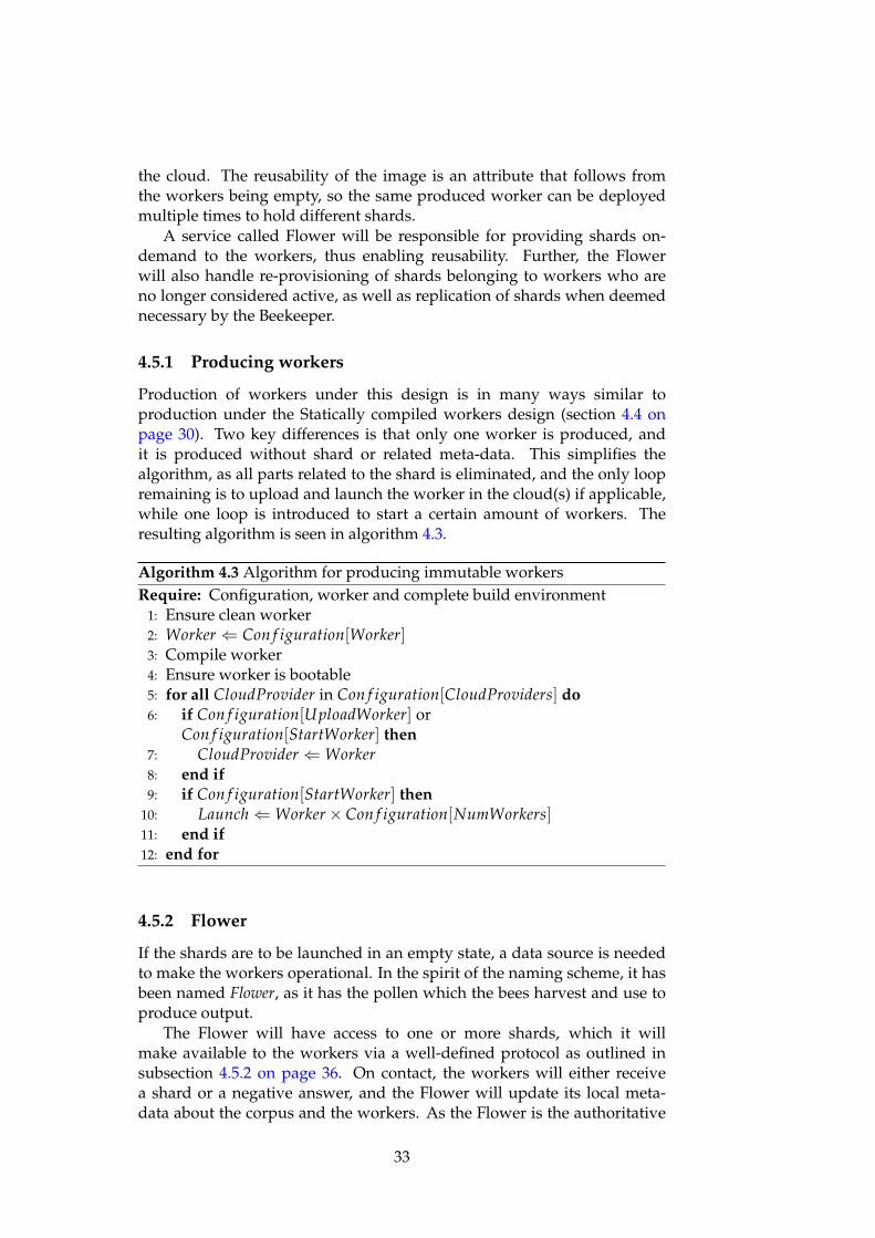
4.5.1 Producing workers
Production of workers under this design is in many ways similar toproduction under the Statically compiled workers design (section 4.4 onpage 30). Two key differences is that only one worker is produced, andit is produced without shard or related meta-data. This simplifies thealgorithm, as all parts related to the shard is eliminated, and the only loopremaining is to upload and launch the worker in the cloud(s) if applicable,while one loop is introduced to start a certain amount of workers. Theresulting algorithm is seen in algorithm 4.3.
Algorithm 4.3 Algorithm for producing immutable workersRequire: Configuration, worker and complete build environment
1: Ensure clean worker2: Worker ⇐ Con f iguration[Worker]3: Compile worker4: Ensure worker is bootable5: for all CloudProvider in Con f iguration[CloudProviders] do6: if Con f iguration[UploadWorker] or
Con f iguration[StartWorker] then7: CloudProvider ⇐Worker8: end if9: if Con f iguration[StartWorker] then
10: Launch⇐Worker× Con f iguration[NumWorkers]11: end if12: end for
4.5.2 Flower
If the shards are to be launched in an empty state, a data source is neededto make the workers operational. In the spirit of the naming scheme, it hasbeen named Flower, as it has the pollen which the bees harvest and use toproduce output.
The Flower will have access to one or more shards, which it willmake available to the workers via a well-defined protocol as outlined insubsection 4.5.2 on page 36. On contact, the workers will either receivea shard or a negative answer, and the Flower will update its local meta-data about the corpus and the workers. As the Flower is the authoritative
33

Type InformationCorpus ID, ShardsShard ID, Corpus, Location, Replica target, Replica
count, WorkersWorker ID, Shard, Status, Last seen
Table 4.2: The metadata tracked by the flower
source regarding the state of the corpus, it will handle provisioning, re-provisioning and replication of shards.
Structure
In figure 4.4, the structure of the flower is illustrated. The heart of theflower is the Shard tracker, which keeps track of meta-data required for theFlower to operate correctly. This meta-data consists of worker information,shard information and corpus information, and is specified in table 4.2.Further, to allow for asynchronous handling of worker connections, it isdesigned with handlers that will act as an agent between the worker andthe shard tracker.
Shard tracker
Handler .... Handler
Worker Worker
Figure 4.4: Structure of the flower.
Workflow
When the worker makes contact with the Flower, it will be to perform oneof two actions; check in, or request a shard. In any case, the handler infigure 4.4 will take care of the contact with the worker, as commanded bythe shard tracker.
34

On check in, the handler will only pass the message on to the shardtracker, so that the shard tracker can perform necessary updates to theworker making contact, such as updating its status and last seen time. Ifthe worker requests a shard, the handler will pass the message to the shardtracker, and wait for its response. The shard tracker will then see if there isany available shards, and issue a response to the handler reflecting if thereis any available shards, leaving the rest of the connection handling to thehandler.
Lifecycle of a worker
If the shard tracker is to to know the status of workers and shards, thereneeds to be a defined lifecycle. Such a suggested lifecycle is shown infigure 4.5, where the different statuses and their relation to each other isillustrated.
Unallocated
Transport
Allocated
Stale
ReservedOnallocation
Transportstarted
Transportfinished
Transport neverstarted
Transportaborted
Worker failed tocheckin
Workerconsidered
inactive
Worker checkin
Figure 4.5: Lifecycle of a worker.
All workers start out with the status Unallocated. When a workersubmits a shard request, and a shard is ready, it transitions into the Reservedstate, so that neither the shard or worker is assigned twice. When transportbegins, it moves into the Transport state, so that the shard tracker is awarethat the shard is currently underway. When transport is finished, theworker transitions to the Allocated state, which it will remain in the restof its lifetime.
However, the world is not perfect, and faults do occur. If transportis never started or aborted, the worker and shard will move back to theUnallocated state, to avoid that the shard remains inaccessible. Further, ifa worker fails to check in for some predetermined time, it will transitionout of the Allocated state to the Stale state. This serves as an indication thata worker might be failing or struggling, and if the worker further fails tocheck in, the worker and shard will be moved back to the Unallocated state.
35

Provisioning of shards
Provisioning occurs when a shard is allocated to a worker, and is equalfor both initial and re-provisioning. The shard tracker will be responsiblefor initial designation of a shard to a worker, as well as regular updates tothe status of the worker and shard in accordance to the lifecycle explainedin subsection 4.5.2 on the previous page. The handler will be responsiblefor the actual sending of the shard to the worker, as well as providing theshard tracker with regular updates so that the shard tracker has correctinformation for the corpus.
Replication
While the actual replication will be handled by the shard tracker, determ-ining if there is a need to replicate any of the shards is handled by theBeekeeper.
Communication protocol
To support the actions outlined above, a communications protocol must beestablished. This protocol will be make use of JSON objects, which makesthe protocol easily extendible and well-defined in terms of grammar andstructure.
For messages from the worker, the design outlined two types ofmessages; check in and request for shard. As the messages also need toidentify the worker, the resulting json object is seen in listing 4.1.
Listing 4.1: JSON-object from worker to Flower
1 {2 "type": "checkin" or "request_shard",3 "id": <worker id>,4 "cid": <corpus id>,5 "shid": <shard id>,6 "working_on": [<job ids >],7 "result_list": [<results >]8 }
Reply from the worker only occurs when a shard request comes in. Thetwo types of messages are no shard available, and shard available. If noshard is available, it simply sends a reply with type "no_shard". When ashard is available, a reply will be sent like the one seen in listing 4.2 on thenext page.
36

Listing 4.2: JSON-object from Flower to Worker
1 {2 "type": "no_data" or "shard",3 "shard": {4 "key": "value"5 },6 "cid": <corpus id>,7 "shid": <shard id>,8 }
To enable replication of shards, the Flower must be able to receivereplica updates from the Beekeeper. The message sent is seen in listing 4.3.Updates to the shards are served as a sub-json object containing updates inthe form of key-value pairs, where the key is the shard and the value is theupdate to the replica goal.
Listing 4.3: JSON-object from Beekeeper to Flower
1 {2 "type": "replica_update",3 "cid": <corpus id>,4 "shards": {5 <shid >: 16 }7 }
4.5.3 Worker-management
In contrast to statically compiled workers, this workflow will produceempty workers which will request and receive a shard from the Flower.Worker-management will thus consist of two tasks, which are shardallocation and replication.
For shard allocation, a Flower service will be utilized. As explained insubsection 4.5.2 on page 33, the Flower will make shards available to theworkers and monitor the allocation state of the shards it has access to. Itwill then be the authoritative source on the allocation state of the individualshards, so it will automatically allocate and replicate shards based on theinput from the Beekeeper.
The Beekeeper will be responsible for monitoring runtime of individualjobs, and scale any workers it may find to be underperforming, such aswhen the runtime of jobs are severely limited by the slowest worker. Thismeans that the Replicate function in algorithm 4.1 on page 30 will send areplica update message to the Flower, and boot one or more new worker(s)in the cloud depending on the need.
37

38

Chapter 5
Result II: Implementation
To validate the designs proposed in Chapter 4 on page 23, a prototypewas implemented. This chapter will illustrate the inner workings of theworker and the Beekeeper, before it moves on to the two proposed designsfor worker-management.
5.1 The Worker
To enable testing of the two different designs outlined in the design chapter,a worker has to be available. Based on the worker model described insection 4.2 on page 25, a prototype worker has been developed in C++ toenable testing and validation. This worker is largely the same for bothStatically compiled workers and Dynamically provisioned empty workers,where the key difference is that only one version of the worker will fetchshards from a data source.
5.1.1 Structure
In figure 5.1 on the next page, almost all the dependencies between thesource files for the worker can be seen. Logging.cpp and configuration.cpphas been left out, as all source files depends on those.
Since the network component in IncludeOS is event-based, it wasdecided go for a function-based style with some global variables for eachfile, instead of an Object Oriented programming style. The global variablesare used when necessary to hold state that is required to persist betweenevents, such as the data structure which holds the shard.
A library called rapidjson is used to provide JSON objects for theworker. The library is designed to be fast, memory-friendly and unicodefriendly, while complying with the de facto standard for JSON objects,ECMA-404.
39

queen.cpp
- job: rapidjson::Document- worker_data: rapidjson::Document- currently_working: int- current_job_finished: int- last_contact_with_queen: time_t
+ initialize_queen(int): void- queen_connect() static void- handle_queen_on_read( const std::string& ): void- handle_job( const Document& ): void- clear_for_new_job(): void- place_finished_job_in_result_list(): void- fetch_sub_document(const rapidjson::Document& , const char*, const int): rapidjson::Document
reduce.cpp
+ reduce_function(std::string): std::string
map.cpp
+ map_function(std::string): std::string
data.cpp
+ data_collection: rapidjson::Document- last_contact_with_flowerbed:
+ initialize_data(int): void- connect_to_flowerbed(): static void- build_data_collection(std::string&): int- read_and_create_new_item(const std::string&, size_t[]): void
service.cpp
+ Service::start(): void- random_string( size_t ): std::string
Figure 5.1: Dependencies of the worker source files. Note that all files alsohas a dependency to configuration.cpp and logging.cpp
5.1.2 Configuration
To provide consistent configuration variables to all parts of the worker, aconfiguration object is used, which is located in configuration.cpp. Thisconfiguration object is provided via the singleton pattern, meaning that allaccess to the configuration is provided though an access-function, whilethe constructor is hidden.
In listing 5.1 on the facing page, the access-function is shown. Since it’sthe only function that provide access to an instance of the Config class, itguarantees that all parts of the code access the same configuration objectfrom memory, and that an object is created on first access.
40

Listing 5.1: Singelton access-function
24 Config * Config : : getConfigObj ( ) {25 i f ( ! i s I n s t a n t i a t e d ) {26 a c t u a l = new Config ( ) ;27 i s I n s t a n t i a t e d = t rue ;28 }29 return a c t u a l ;30 }
Listing 5.2: Communication timer for queen.cpp and data.cpp. Note thatonly the function name on line 4 differ between the two.
1 Timers : : p e r i o d i c (1 s , s td : : chrono : : seconds (c o n t a c t _ i n t e r v a l ) ,
2 [ ] ( u i n t 3 2 _ t )3 {4 connect_to_f lower ( ) ;5 } ) ;
5.1.3 Communication for queen.cpp and data.cpp
The model for the worker stated that both the query component(queen.cpp) and the data component (data.cpp) were to rely on the net-work component. To solve this, both files have a communication functionon a timer (listing 5.2), which is started in the initialization functions calledby service.cpp.
However, while contact with the Queen and the Flower have the samestructure, there are several differences, with the biggest being how theyhandle sending and receiving. Due to this, the two files have their ownimplementations of the function listed in appendix A on page 75, withdifferences listed in table 5.1 on the next page.
5.1.4 Communication with the Queen
Queen.cpp has the functionality used for communication with theQueen and performing any queries on the shard as commandedby the Queen. The only function it exports has the signaturevoid initialize_queen(int contact_interval ) , a function which initializes
the base JSON object sent to the Queen and the timer event which makesthe worker regularly contact the Queen.
As stated in the previous section on communication, queen.cpp has afew differing implementation details from data.cpp. Before it initiates anyconnection attempt, it makes sure that it has the correct Corpus and ShardID stored in the base JSON object, as they may change when the worker isdeployed empty. When connected, if it has a finished query, it will send itto the Queen before erasing the query and its result, so that it is prepared to
41

Placement inthe function
queen.cpp data.cpp
Pre-iface If Corpus ID and Shard IDhas changed, update localJSON object
Nothing
Pre-connection Nothing Check if transfer is in pro-gress
Sending Place query result in localJSON object, send and clearresult from local JSON ob-ject
If the worker has data, sendcheck in, else request shard
Receiving Read full response intovariable
Skip read if a checkin wassent, else read response andadd documents on the fly
Disconnect Check response Check if transfer finished,reset data collection if it didnot
Table 5.1: Notable differences in the connect implementation
work if the Queen sends a new query in the reply. Also, as the replies fromthe Queen are small and to avoid hanging connections, it reads the wholeanswer into a variable, and defers parsing till disconnect.
When a new job arrives, it creates a JSON object for the query with thenecessary metadata, executes the map function and updates the remainingmetadata for the query and for the worker. As IncludeOS does not have aneasy way to get threaded concurrency, this process will block the workeruntil it has finished.
5.1.5 Handling the shard
To handle the shard for the worker, data.cpp has the necessary datastructure for storing the shard in memory, as well as the functionality forrequesting a shard from a Flower. Like queen.cpp it exposes an initializerfunction with the signature void initialize_data (int contact_interval ) ,but in contrast to queen.cpp, this function varies between the two designs.
Dynamically provisioned empty workers
For the Dynamically provisioned empty workers design, it sets up a timerlike seen in listing 5.2 on the preceding page. The function called tocontact the Flower is designed to avoid unnecessary contact and to limitthe amount of memory used during reception of a shard.
Avoiding unnecessary contact is done by setting a flag in the config-uration object during transfer, so that new contact attempts are skipped iftransfer of a shard is in progress. Limiting the amount of memory used fortransfer purposes is done out of necessity, as a shard can potentially fill the
42

Listing 5.3: Function for parsing document id and document out of a string
1 void read_and_create_new_item ( const std : : s t r i n g&incoming_data , s i z e _ t pos [ ] ) {
2 / *3 pos has t h e f i r s t and l a s t p o s i t i o n f o r t h e document i d
and f o r t h e document in t h e i n c o m i n g _ d a t a s t r i n g4 +1 on f i r s t p a r a m e t e r t o drop t h e " a t t h e s t a r t o f t h e
s t r i n g5 * /6 rapid j son : : Value docid (7 incoming_data . subs t r ( pos [ 0 ] + 1 , pos [1]−pos [ 0 ] ) . c _ s t r ( ) ,8 pos [ 1 ] − pos [ 0 ] − 1 ,9 d a t a _ c o l l e c t i o n . GetAl locator ( ) ) ;
10 rapid j son : : Value document (11 incoming_data . subs t r ( pos [ 2 ] + 1 , pos [3]−pos [ 2 ] ) . c _ s t r ( ) ,12 pos [ 3 ] − pos [ 2 ] − 1 ,13 d a t a _ c o l l e c t i o n . GetAl locator ( ) ) ;14 i f ( strcmp ( docid . GetStr ing ( ) , " shid " ) == 0 ||15 strcmp ( docid . GetStr ing ( ) , " c id " ) == 0 ) {16 auto * conf = Config : : getConfigObj ( ) ;17 conf−>setID ( docid . GetStr ing ( ) , document . GetStr ing ( ) ) ;18 conf−>setDataCol lec ted ( t rue ) ;19 } e lse {20 d a t a _ c o l l e c t i o n . AddMember(21 docid ,22 document . Move ( ) ,23 d a t a _ c o l l e c t i o n . GetAl locator ( ) ) ;24 }25 }
memory of the worker. The solution for this is to read the received data intoa buffer, and extract document and document ids from that buffer, which isdone by the function in listing 5.3. After the document has been inserted,the calling function removes the document id and document from the buf-fer, thereby limiting the size of the buffer used for data received from theFlower.
Statically compiled workers
When the worker is Statically compiled, the initialization function ispopulated with create and insert commands for the document ids anddocuments, replacing the timer function completely. Creation and insertionis done in the same way as listing 5.3, but with the document ids anddocuments inserted directly into the source files by the build script.
43

5.1.6 The Map function
The mapping function, called map_function, is defined in map.cpp. Itprovides a function that takes as input a query, and returns a string of key-value pairs.
To support multiple queries, a function object is populated by a lambdaexpression based on the received query, as shown in listing 5.4. By utilizingthe mapper variable, we can easily check if a valid query was sent bychecking if mapper is defined. Further, performing the query is then assimple as calling the mapper function on each documentid-document pair,and storing the result in a buffer which is returned when all the documentshas been checked.
Extending with more queries is also simple, as one would only have toadd a new if-statement and lambda expression for the query wanted.
Listing 5.4: Example assignment of a lambda expression to the mapperfunction variable
1 i f ( ! strcmp ( "WORDCOUNT" , function_name . c _ s t r ( ) ) ) {2 mapper = [& funct ion_query ] ( s td : : s t r i n g id , s td : :
s t r i n g val ) −> std : : s t r i n g {3 std : : s t r i n g re s ;4 s i z e _ t c u r r _ h i t = val . f ind ( funct ion_query ) ;5 while ( c u r r _ h i t != std : : s t r i n g : : npos ) {6 re s += " [\" " + funct ion_query + " \ " , 1 ] , " ;7 c u r r _ h i t = val . f ind ( function_query ,
c u r r _ h i t +1) ;8 }9 return r es ;
10 } ;11 }
5.1.7 Minor files
service.cpp
Service.cpp contains the entry point of the binary, a function calledService::Start. It is only responsible for setting up the worker ID if noneexist, as well as calling the setup functions functions from queen.cpp anddata.cpp.
logging.cpp
This file holds the logging functionality, which currently is implementedthrough formatted print statements containing the arguments passed.
44

reduce.cpp
This is a dummy file supposed to handle reduce functionality, but is notimplemented.
5.1.8 IncludeOS
In section 4.2 on page 25, it is stated that the worker will be based on theunikernel operating system for C++ called IncludeOS. However, to turn aC++ program into a bootable image using IncludeOS, some adaptions ofthe source code must be made, and the produced image must be processedto make it cloud-ready.
Source file adaptions
To create a functional IncludeOS based C++ program, there are twochanges every regular C++ programs need to implement. One change isto include the IncludeOS library, via #include <os> and a custom GCC-based toolchain. This will ensure that the necessary libraries are linkedwith the produced binary, or as they state in the IncludeOS paper[6];
Using a custom GCC-based toolchain, writing #include <os>will literally Include the operating system.
The second change is the entry point of the program. For C++ programsrunning on a regular operating system, such as Ubuntu or Windows, theentry point is defined as the main-function, but for programs running inother environments, it is up to the implementation[11]. IncludeOS haselected that the entry point will be a function called Start in a class calledService, so void Service :: Start () is the entry point of the program.
To sum it up in implementation details, to make use of IncludeOS to cre-ate a bootable image out of the C++ source files for the worker, service.cpphas the implementation of the function void Service :: Start () to provide
the program with an entry point, and service.hpp has #include <os> .
Creating a bootable image
To create a bootable binary file, it is as simple as running the followingcommands from the repository containing the code;
mkdir bui ldcd bui ldcmake . .make
However, while the produced binary is bootable under the hostedhypervisor Qemu, it will not easily work on other hypervisors or in thecloud. To fix this, we attach a GRUB bootloader using one of the toolsmade by IncludeOS;
boot −bg tworker # t w o r k e r i s t h e produced b i n a r y
45

5.2 Beekeeper
As both designs has replication of worker as a part of the workermanagement, a working prototype of the Beekeeper was developed.This prototype is based of section 4.3 on page 28 in the design chapter.Further, the implementation adopts a slow replication strategy, meaningthat whenever a worker should be scaled, only 1 extra shard is added.
5.2.1 Discovering corpuses
Since the Queen does not have any method for serving job information forall corpuses in one message, the Beekeeper must maintain its own list ofcorpuses, which it uses to query job information. To discover new corpuses,the Beekeeper fetches the list of workers from the Queen, which lists thecorpus and shard for each worker. The corpus listed in the response is thenextracted, and if necessary, inserted into the local data structure.
5.2.2 Deciding on replication
Deciding on wether to replicate any of the workers, is performed by thefunction in listing 5.5 on the facing page. The corpuses it loops over arethe ones gathered via the worker list from the Queen, and since the Queendoes not report on which worker was the last one to finish, the Beekeepermust find that shard manually.
5.2.3 Performing replication
To perform replication, the Beekeeper is able to launch new workers in thecloud. However, given the fundamental differences in how the workersunder the two designs handle the shard, it employs different functionalityfor each design. As such, the replication will be explained for Staticallycompiled workers under section 5.3 on page 48, and for Dynamicallyprovisioned empty workers under section 5.4.2 on page 53.
46

Listing 5.5: Implementation of the function used to calculate ratios for alljobs
1 def f e t c h _ w a i t _ r a t i o s ( s e l f ) −> d i c t :2 upd_shid = { }3 for c id in s e l f . corpuses :4 job_data = s e l f . __send_and_recv ( s e l f . queen , { " corpus " :
cid , " type " : " s t a t s _ r e q u e s t " } )5 i f not job_data or ’ j o b _ l i s t ’ not in job_data :6 continue7 for job in job_data [ ’ j o b _ l i s t ’ ] :8 i f job [ ’ j i d ’ ] in s e l f . seen_ jobs or "DtMax" not in job :9 continue
10 i f c id not in upd_shid :11 upd_shid [ c id ] = { }1213 r t 9 5 = f l o a t ( job [ ’Tw95 ’ ] ) / f l o a t ( job [ ’ Tt ’ ] )14 i f r t 9 5 < s e l f . slowRatio :15 upd_shid [ c id ] [ job [ ’TwMax ’ ] [ 0 ] ] = 11617 rtmax = f l o a t ( job [ ’TwMax ’ ] ) / f l o a t ( job [ ’ Tt ’ ] )18 i f rtmax < s e l f . l a s t R a t i o :19 s h i d _ l a s t = ( " " , 0 )20 for shid , shid_data in job [ " s h i d _ l i s t " ] . i tems ( ) :21 i f shid_data [ " t ime_f in i shed " ] > s h i d _ l a s t [ 1 ] :22 s h i d _ l a s t = ( shid , shid_data [ " t ime_f in i shed " ] )23 upd_shid [ c id ] [ s h i d _ l a s t [ 0 ] ] = 12425 s e l f . seen_ jobs . append ( job [ ’ j i d ’ ] )26 return upd_shid
47

5.3 Statically compiled workers
The first design is to Statically compile workers with shards. To achievethis, a build script written in python was implemented, and central pointswill be outlined in this section.
To make the script configurable, it accepts parameters via the commandline and a yaml-file. By giving the command line precedence over the yaml-file, one can have a baseline configuration where individual options can beoverridden ad-hoc.
5.3.1 Pre-build
Before the script starts building workers, it sets up the build environment,with a folder structure as seen in figure 5.2. The all folder contains the folderused by the build process, the template folder contains the source files whichwill be used to build workers, and the images folder is an optional folder.Further, the configuration file for the worker is read into a variable andthe Corpus ID is inserted, prepping it part-way to be written to file for theworkers, and the Corpus file is opened for reading.
Figure 5.2: Folder structure used during buildbuild
all
1
template
patches
src
CMakeLists.txt
CMakeLists-libs.txt
config.json
images
5.3.2 Clean
At the start of each build step, the build script makes sure that the folder isclean by replacing source files with clean ones from the template folder, aswell as removing produced images from the previous run.
5.3.3 Build
Before the worker is compiled, the source files are prepped. The shard idand worker id is written to a local version of the configuration variable,
48

which is then written to configuration.cpp. The last step before compileis then to read the number of key-value pairs which the worker will holdfrom the corpus file, and write it in a formatted manner to the data.cpp file.When that is done, the commands from section 5.1.8 on page 45 to create abootable image with grub.
5.3.4 Cloud
The last part takes care of the produced image. Depending on theconfiguration of the build script, this part can store the image in the imagesfolder as well as upload the image to the cloud and launch it. This is alsothe step were the name of the image is changed to reflect which shard itcontains, by adding _<shardid> to the end of the filename, both when itstore the image locally and when uploading the image. The command toupload the images is seen in listing 5.6, and the command to launch theworker is seen in listing 5.7.
Listing 5.6: Command to upload images of precompiled workers
glance image−c r e a t e −−disk−format raw \−−property hw_disk_bus=ide \−−conta iner−format bare \−− f i l e tworker . grub . img \−−name tinyworker_ <shid >
Listing 5.7: Command to boot new workers based of pre-compiled images
nova boot −−image tinyworker_ <shid > \−−f l a v o r m1. small \−−nic net−name=includeOS_net \tinyworker_ <shid >
5.3.5 Replication management with Beekeeper
Replication under this design is done by launching new images containingthe shard to be replicated. Further, as the Beekeeper does not know whichshard is compiled into which image, correct labeling of the workers arecritical. To solve this, a simple naming scheme for the uploaded images wasselected, which is to add -<shid> at the end of the uploaded images. Thus,the beekeeper simply issues the command in listing 5.7 to boot images.
5.4 Dynamically provisioned empty workers
The second design moves the complexity out of the build process, and intoa shard tracking process called Flower. This gives a build process wherethe only necessary pre-build step is to write the general configuration tothe worker, meaning Queen and Flower contact information. Further, asthe worker created from the build step is without any corpus or shard
49
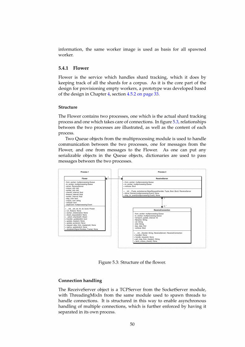
information, the same worker image is used as basis for all spawnedworker.
5.4.1 Flower
Flower is the service which handles shard tracking, which it does bykeeping track of all the shards for a corpus. As it is the core part of thedesign for provisioning empty workers, a prototype was developed basedof the design in Chapter 4, section 4.5.2 on page 33.
Structure
The Flower contains two processes, one which is the actual shard trackingprocess and one which takes care of connections. In figure 5.3, relationshipsbetween the two processes are illustrated, as well as the content of eachprocess.
Two Queue objects from the multiprocessing module is used to handlecommunication between the two processes, one for messages from theFlower, and one from messages to the Flower. As one can put anyserializable objects in the Queue objects, dictionaries are used to passmessages between the two processes.
Flower
- from_worker: multiprocessing.Queue- to_worker: multiprocessing.Queue- server: ReceiveServer- corpus_info: dict- worker_info: dict- checkin_interval: float- timeout_interval: float- worker_interval: float- stop_now: bool- corpus_root: string- verbose: bool- stopEvent: multiprocessing.Event
+ __init__(int, str, int, str, bool): Flower+ run_flower(): None+ worker_checkin(dict): None+ shard_request(dict): None+ _select_shard(self): Shard+ transfer_update(dict): bool+ update_master(): None+ update_workers(): None+ request_data_from_master(str): None+ replica_update(dict): None+ shutdown(Signal Number, Frame): None
ReceiveServer
+ from_worker: multiprocessing.Queue+ to_worker: multiprocessing.Queue+ verbose: Bool
+ __init__(Tuple, socketserver.BaseRequestHandler, Tuple, Bool, Bool): ReceiveServer+ serve_forever(multiprocessing.Event): None+ stop_on_event(multiprocessing.Event): None
ReceiveConnection
- from_worker: multiprocessing.Queue- to_worker: multiprocessing.Queue- transport_update_interval: Int- filename: String- cid: String- shid: String- bee_data: Dict- verbose: Bool
+ __init__(Socket, String, ReceiveServer): ReceiveConnection+ handle(): None+ handle_request(): None+ get_msg_from_master(): String+ send_corpus_shard(): None
1 1
1
0..*
Process 1 Process 2
Figure 5.3: Structure of the flower.
Connection handling
The ReceiveServer object is a TCPServer from the SocketServer module,with ThreadingMixIn from the same module used to spawn threads tohandle connections. It is structured in this way to enable asynchronoushandling of multiple connections, which is further enforced by having itseparated in its own process.
50

For each thread, an object of the class ReceiveConnection is spawned,which is the handler for each connection. The payload received is firstensured to be valid json containing the key Type, before it is passed onto the Flower through the queue. Three examples of communication isillustrated in the sequence diagram in figure 5.4.
ReceiveConnection BeeFlower
Request shardRequest shard
No shard
Request shardRequest shard
Assign shard
Transfer shardTransfer start
Transfer cid and shidTransfer finished
Transfer update
CheckinCheckin
Figure 5.4: Communication between Flower, ReceiveConnection and Bee.Note that each arrow from Bee to ReceiveConnection means that a newinstance of ReceiveConnection is instantiated
The only message that will be handled further by the thread has thevalue Request_shard in the Type key, which is the message received froma worker without a shard. On receiving such a message, the handler willwait for a response from the Flower. If the response contains no_shard,the connection is closed, signaling to the worker that there is currentlyno available shard. The other possibility is that the response contains thefilename, shard and corpus id of the shard, leading the handler to start thetransfer of the shard located in the file indicated by the filename.
During transfer, the handler will send regular updates to the Flower,which will work as a checkin for the worker. When the handler has finishedtransferring the shard, it will send the shard and corpus id to the workerand notify the Flower object about the completed transfer. The transfermessages are the same, but with different types, and are seen in listing 5.8on the next page.
51

Listing 5.8: JSON from ReceiveConnection object to Flower object duringtransfer
1 {2 "type": "transfer_start" or "transfer_update" or
"transfer_finished,3 "id": <worker id>4 }
Shard tracking
The Flower object is responsible for tracking the shards. It does so bykeeping a representation of all known corpus, shards and workers inmemory, using a data structure which is illustrated in figure 5.5.
Corpus
+ id: String
+ shards: Dict
Shard
+ id: String
+ corpus: Corpus
+ filename: String
+ replica_target: Int
+ replica_wanted: Int
+ workers: Dict
Worker
+ id: String
+ shard: Shard
+ status: Status
+ last_checkin: Time
Status(enum)
+ unallocated
+ reserved
+ transport
+ allocated
+ stale
1
1..*0..1 0..* 0..* 1
Figure 5.5: Data structure used by flower.
The in-memory representation of the shards and the corpus is built onstartup, by parsing corpus and shard ids from the filename for each shard.The naming scheme used for the shards is corpusid_shardid.json. The objectsused to represent workers are built when unknown workers connect to theFlower, no matter if the worker performs a check in or requests a shard.
During runtime, the main event loop of the Flower will react tomessages from the ReceiveConnection objects, of which four possibleevents can occur; checkin, request shard, replica update and transferinformation. Each 30-40 seconds, depending on the last event, the eventloop will write a textual representation of all known shards and workers tothe log, as well as call the update function for all the workers. The updatefunction will check if the worker has checked in the last 40 seconds, and ifnot, move the worker into the next state as per the diagram in figure 4.5 onpage 35. If the worker is moved into the unallocated state, it will also bedisconnected from the shard.
52

A checkin event is triggered by messages received from the worker,where the message has a Type containing Checkin. This event simplycreates a worker object if one does not exist, and updates the workers lastcheckin variable.
The request shard event is triggered by messages received from theworker where the value Request_shard is in the Type field. On thisevent, the Flower will first check if any shards are available. If no shardis available, a message like the one in listing 5.9 is sent back to theReceiveConnection queue. If a shard is available, a connection between theworker and shard is established in the internal data structure, the replicacount for the shard is updated and the worker is moved into the nextstate. A message with content as seen in listing 5.10 is then sent to theReceiveConnection queue.
Listing 5.9: JSON from Flower object to ReceiveConnection object when noshard is available
1 {2 "type": <worker id>,3 "val": "no_shard"4 }
Listing 5.10: JSON from Flower object to ReceiveConnection object when ashard is found
1 {2 "type": <worker id>,3 "cid": <corpus id>,4 "shid": <shard id>,5 "val": <filename of shard >6 }
Transfer events are triggered by transfer messages from the Receive-Connection objects, and will always trigger a check in for the worker men-tioned in the message. If the transfer type is started or finished, the Flowerwill also move the worker into the next state.
The last event is triggered by replication messages sent from theBeekeeper. The Flower will iterate through the shards listed in the message,and update the replica target for each shard. Note that the function forupdating the replica target takes a number which is added to the replicatarget, allowing for both positive and negative scaling.
5.4.2 Replication management
For Dynamically provisioned empty workers, the Beekeeper has toperform two steps to scale one or more shards. The first step is to check ifthere exists enough empty workers for the update, and if not, launch newworkers to cover the new need. The second step is to issue an update to theflower, where shard ids are listed with the update value. The message sentfrom the Beekeeper to the Flower is shown in listing 5.11.
53

Listing 5.11: JSON from Beekeeper to Flower when one or more shards areto be replicated
1 {2 "Type": "Request_shard",3 "Corpus": <corpus id>,4 "Shards": {5 <shard id>: <update >,6 ...7 <shard id>: <update >8 }9 }
54

Chapter 6
Experiments and analysis
6.1 Test environment and Corpus
All builds and experiments were done using the cloud at Oslo MetropolitanUniversity called ALTO, a private cloud running OpenStack. The virtualmachine used for the experiments runs Ubuntu 16.04, has 16GB Ram and 8Virtual CPUs.
The corpus used is a Fasta-formatted file with 166355 sequences. Thesequence name is used as the document ID, while the sequence itself isused as the document.
6.2 Statically compiled workers
To test the statically compiled workers prototype, a driver script wascreated to build 2 to 50 workers using the produced build script. Thetotal runtime for each build run is plotted in a graph in figure 6.1 on thenext page, and the build time for individual workers is plotted in 6.2 onthe following page. To provide a readable graph, a log-linear plot is used,indicating that the runtime increases in logarithmic space with the size ofthe shards once the shards reach some size.
As seen in figure 6.1 on the next page, even though the number ofshards and workers decrease, the total runtime increase. While the increasein runtime holds an average growth rate of 1.12% from 50 workers to 21workers, it jumps to 8.64% from 20 workers. The same is seen in the graphshowing individual run times, with a jump from 4.04% to 16.6%. Note thatthe amount of 2 and 3 workers are left out, as they failed to build.
Building 2 and 3 workers failed, seemingly due to the size of the shards.The problem seems to occur when a shard reaches 1.8GB in size, as workerswith a shard of that size experienced a segmentation fault in the compiler.This failure was in all likelihood caused by a combination of size and thenumber of variables in the data file, but debugging this problem furtherwas deemed as out of scope for this thesis.
55

23 5 10 15 20 25 30 35 40 45 50Number of workers
4000
6000
8000
1000
10000
2000
20000
4000
6000
8000
2000
20000
4000
6000
8000
2000
20000
3000
Seco
nds
Compiler runs out of memory
Growth rate of time spent increases
Total time taken for all workers
Figure 6.1: Total runtime when building static workers. Note that the y-axishas a logarithmic scale.
23 5 10 15 20 25 30 35 40 45 50Number of workers
400
4000
60
600
6000
80
800
100
1000
200
2000
400
4000
60
600
6000
80
800
200
2000
400
4000
60
600
6000
80
800
200
2000
300
3000
Seco
nds
Average time taken for a workerShortest time taken for a workerLongest time taken for a worker
Figure 6.2: Min, average and max time when building static workers. Notethat the y-axis has a logarithmic scale.
56

Table 6.1: Mean and Standard deviation for time used to split the corpus,launch workers and for all workers to report a shard and CID
Run #Mean Standard deviation
Split Create Report ready Split Create Report ready1 268.38 127.99 1903.69 13.31 40.92 2716.792 262.27 128.96 1219.29 7.15 37.07 1478.603 269.04 120.97 786.54 9.57 25.44 1409.644 264.47 109.82 2190.17 7.05 22.76 1684.055 265.68 117.93 499.59 4.37 33.74 943.09Total 265.97 387.10 1706.96 9.16 35.83 1844.97
6.3 Dynamically provisioned empty workers
A new version of the driver script from the previous section was written totest the Dynamically provisioned empty workers prototype. It was setup tocreate and assign shards to 5-50 workers in 5 worker increments, repeatingthe run 5 times.
To analyze the runs, each run was divided into three stages; split, createand report ready. The split stage is the time it takes to divide the corpusinto shards, based on how many workers there will be. The create stage isthe time taken to build an empty worker, and boot up the required amountof workers. The report ready stage is the time it takes for all workers toreceive a shard.
In table 6.1, the mean time and standard deviation for each stage islisted. It shows that while the split and create stages are relatively equalfor all runs, the report ready stage has a high degree of variation. Thisis illustrated further in figure 6.3 on the next page, where the time spenthanding out shards for the different runs is plotted. As can be seen, thevariation is not simply due to shards growing bigger, since variation occursfor the same amount of workers/shards, but in different runs.
Further investigation of the numbers revealed that a great amount oftime was spent sending the last shard. In figure 6.4 on the following page,the percentage of the total time spent waiting for the last time is plotted. Itis shown via the maximum, average and minimum percentage of total time,as well as +/- one standard deviation away from the average. The exactreason for this was not uncovered, as it seemed to be caused by the internalworkings of python, and/or where the worker was placed physically inrelation to the flower.
57

:
10 20 30 40 50Number of workers
2000
4000
6000
8000
10000
Seco
nds
Run #1Run #2Run #3Run #4Run #5
Figure 6.3: Time spent handing out shards by the flower.
10 20 30 40 50Number of workers
0
20
40
60
80
100
120
% o
f tot
al ti
me
to d
eliv
er sh
ards
MaximumMeanMinimum
Figure 6.4: Maximum, average and minimum percentage of total timespent handing out the last shard. The gray area is +/- one standarddeviation from the average.
58

6.4 Query experiments
To investigate how the workers and the beekeeper perform, a clusterof 20 shards was used, with workers provisioned by the Dynamicallyprovisioned empty workers prototype. Three different queries were used,and each query was executed 7 times before and after the beekeeper hadperformed replication of the cluster. Further, to provide variety in runtimefor each executed query, 7 different values were used.
Between the measured runs, three queries of type Word count wereperformed, with a pause between each query so that the replication ofshards ordered by the beekeeper is completed. The resulting cluster wasthen used to perform the three queries one more time.
6.4.1 Grep
The first query experiment use the query Grep, which is a query where themap function returns the tuple <query-word, 1>, once for each document.The query supports regex, which makes it a computationally expensivequery, while also allowing more freedom.
While the total time for all queries to complete drops by 13.7%, the timeto complete a job increases by 371.8%, as seen in table 6.2. The cause isseen in figure 6.6 on the following page, where some shards have severalreplicas, such as shard 14 with 6, while others only have one, such as shard8 and 11.
Total Mean start time Mean job timePre-beekeeper 393 78.3 45.25Post-beekeeper 339 13.3 213.5Change -13.7% -83% +371.8%
Table 6.2: Runtime, mean start time and mean job time for Grep
59

0 50 100 150 200 250 300 350 400Time
0.0
1.0
2.0
3.0
4.0
5.0
6.0
7.0
8.0
9.0
10.0
11.0
12.0
13.0
14.0
15.0
16.0
17.0
18.0
19.0
Shar
d
Job #1Job #2
Job #3Job #4
Job #5Job #6
Job #7
Figure 6.5: Grep query without replicated shards.
0 50 100 150 200 250 300 350Time
0.00.20.40.60.81.02.03.04.0
4.334.675.06.06.57.0
7.337.678.09.0
10.011.012.0
12.3312.6713.013.213.413.613.814.0
14.1714.3314.5
14.6714.8315.016.017.018.019.0
Shar
d
Job #1Job #2
Job #6Job #4
Job #7Job #3
Job #5
Figure 6.6: Grep query with replicated shards.
60

6.4.2 Word count
Word count is a query where the map function returns the tuple <query-word, 1>, once or more for each document. This is similar to the Grepquery, but with the possibility that the same search will be executedmultiple times for each document, and without supporting regex.
In figure 6.7, the result of the pre-beekeeper queries is shown . As canbe seen, the total runtime for all the queries to finish is 95 seconds, with5 shards(0, 6, 12, 13, 14) slowing down the time needed to complete aquery. The post-beekeeper queries are shown in figure 6.8 on the followingpage. While the graphs look somewhat similar, note that the total runtimeis down to 52 seconds, and the slowest worker in this graph is now shard11, a shard which previously finished well ahead of the slowest ones.
Total Mean start time Mean job timePre-beekeeper 95 27 28.6Post-beekeeper 52 7.14 27.4Change -45.3% -73.5% -4.2%
Table 6.3: Runtime, mean start time and mean job time for Word count
0 20 40 60 80 100Time
0.01.02.03.04.05.06.07.08.09.0
10.011.012.013.014.015.016.017.018.019.0
Shar
d
Job #0Job #1Job #2
Job #3Job #4
Job #5Job #6
Figure 6.7: Word count query without replicated shards.
61

0 10 20 30 40 50Time
0.00.20.40.60.81.02.03.04.0
4.334.675.06.06.57.0
7.337.678.09.0
10.011.012.0
12.3312.6713.013.213.413.613.814.0
14.1714.3314.5
14.6714.8315.016.017.018.019.0
Shar
d
Job #1Job #6
Job #2Job #7
Job #3Job #5
Job #4
Figure 6.8: Word count query with replicated shards.
62

6.4.3 Inverted index
The last query experiment use the Inverted index function, where the mapworkers return a list of <word, docid> tuples. In contrast to the previoustwo queries, which count the number of documents containing a word andthe number of occurrences in the corpus, this is query returns the specificdocuments that contains a given word.
Similar to the Grep query, the Inverted Index query saw a decrease inboth Total time for all queries and Mean start time for the jobs, and anincrease in the mean time to complete a job.
Total Mean start time Mean job timePre-beekeeper 74 27.9 24.6Post-beekeeper 58 13.3 31.9Change -21.6% -52.3% +29.7%
Table 6.4: Runtime, mean start time and mean job time for Inverted Index
0 10 20 30 40 50 60 70Time
0.01.02.03.04.05.06.07.08.09.0
10.011.012.013.014.015.016.017.018.019.0
Shar
d
Job #1Job #2
Job #3Job #4
Job #5Job #6
Job #7
Figure 6.9: Inverted index query without replicated shards.
63

0 10 20 30 40 50 60Time
0.00.20.40.60.81.02.03.04.0
4.334.675.06.06.57.0
7.337.678.09.0
10.011.012.0
12.3312.6713.013.213.413.613.814.0
14.1714.3314.5
14.6714.8315.016.017.018.019.0
Shar
d
Job #1Job #6
Job #2Job #7
Job #3Job #5
Job #4
Figure 6.10: Inverted index query with replicated shards.
64

Chapter 7
Discussion
7.1 The proposed workflows
Going back to the introduction chapter and the problem statements, themain objective was to develop workflows for efficient worker-managementof a unikernel-based map-reduce cluster. The two proposed workflowsboth solve the task, each showing both strength and weaknesses.
The workflow for producing Static workers showed signs of havinga consistent run-time for the same amount of workers. It also brings theadvantage of having workers that are ready for new queries immediatelyon boot, allowing for very responsible cluster that can adjust up and downon demand, with little lag between adjustments. However, while the run-time was consistent, it also increased as the shards grew fewer and bigger.This seemed to be caused by the compiler itself running out of memorywhile compiling the data file, meaning that one would need a machine withover 16GB of ram for very large shards.
The Dynamic workers showed signs of having a generally low provi-sioning time, and brings the advantage of producing a small worker thatcan quickly be transmitted to new data centers. As the worker is structuredwith modularity and adaptability in mind, it should also be easily extend-ible to support removal of the shard it currently has, making the workerdynamic in its truest sense. There were down sides though, most notablythat on average, the delivery of one shard for a corpus would experienceslow transfer speed compared to the rest, meaning that the readiness ofthe cluster was delayed. However, as it was not consistent which shard orwhat size experienced the problem, the problem might be easier to solvethen expected.
7.2 Future work
7.2.1 Investigate new and intelligent ways to predict new replic-ation goals
The Beekeeper prototype performs replication by measuring the relation-ship between TwMax and Tt, and Tw95 and Tt. While this is a simple way
65

of gaining information about the general state of the corpus the jobs areexecuted on, it is not necessarily the best way, and does not rely on historicdata.
7.2.2 Data center monitoring and migration
While IncludeOS binaries are seen as inherently more effective then acomparable program running in a traditional operating system, automaticmigration of workers to greener or cheaper data centers is a possible venueto explore.
7.2.3 Map-function language
The workers developed in this thesis was compiled with only a smallamount of queries. This can of course be extended with new queries simplyby adding more queries to the map.cpp file for a worker, but a more user-friendly solution could be to develop a simple map-function language andassociated language-engine to handle the query. The same could be said forreduce, as it currently relies on a python script being sent with the query.
7.2.4 Performing query experiments on larger and/or distributedclusters
The experiment section utilized a cluster consisting of 20 shards, and allworkers were located in the Alto cloud at Oslo Metropolitan University.The same experiment could be performed with a larger cluster, or evena larger distributed cluster, where workers are located in different datacenters.
66

Chapter 8
Conclusion
The goal of this thesis was to propose an alternative and greener method toperform map-reduce like computation. This was to be done by defining aworkflow that allows efficient worker-management of a cloud-based map-reduce like infrastructure, based on unikernel technology, and developinga prototype implementation to investigate the performance.
Two workflows were defined to investigate the problem statements, onewhere the workers were compiled with the shards, and one where shardswere dynamically provisioned to empty workers on demand. Further,there was developed two prototypes, one for each workflow, so that theworkflows could be tested in terms of provisioning shards. There was alsoconducted query experiments to measure how the clusters performed, bothwith and without replication of some of the shards.
The prototypes of the workflow showed varied results. The staticallycompiled workers had a pronounced increase in run time to create a clusteras the number of shards went down, while the dynamically provisionedempty workers experienced a high degree of variation in the time it takes toprovision all shards. However, for a substantial amount of runs, it was onlyone shard dragging down the run time for dynamically provisioned emptyworkers, indicating that it may be a solvable problem - in which case, firingup a new cluster would be 10x as fast as with statically compiled workers.
While the query experiments were not conclusive, they did showpromise. All the query experiments did show a decrease in total time toexecute all jobs, as well as a decrease in time to start a job. However,the average time taken to complete a job increased in two out of threeexperiments. By studying the graphs, this seemed to have been causedby a few shards being over-provisioned, while other shards were under-provisioned.
However, unikernel-based map-reduce clusters do show promise, andwarrants further investigation, specifically with regards to tooling andmanagement.
67

68

Bibliography
[1] Michael Armbrust et al. ‘A view of cloud computing’. In: Communic-ations of the ACM 53.4 (2010), pp. 50–58.
[2] Jayant Baliga et al. ‘Green cloud computing: Balancing energy inprocessing, storage, and transport’. In: Proceedings of the IEEE 99.1(2011), pp. 149–167.
[3] Paul Barham et al. ‘Xen and the art of virtualization’. In: ACMSIGOPS operating systems review. Vol. 37. 5. ACM. 2003, pp. 164–177.
[4] Sushil Bhardwaj, Leena Jain and Sandeep Jain. ‘Cloud computing: Astudy of infrastructure as a service (IAAS)’. In: International Journal ofengineering and information Technology 2.1 (2010), pp. 60–63.
[5] A Binu and G Santhosh Kumar. ‘Virtualization techniques: a meth-odical review of XEN and KVM’. In: Advances in Computing and Com-munications (2011), pp. 399–410.
[6] Alfred Bratterud et al. ‘IncludeOS: A minimal, resource efficientunikernel for cloud services’. In: Cloud Computing Technology andScience (CloudCom), 2015 IEEE 7th International Conference on. IEEE.2015, pp. 250–257.
[7] Bryan Cantrill. Unikernels are unfit for production. https://www.joyent.com/blog/unikernels-are-unfit-for-production. [Online; accessed May-2017]. 2016.
[8] Gary Cook et al. Clicking clean: Who is winning the race to build a greeninternet? Greenpeace. 2017.
[9] Jonathan Corbet and Greg Kroah-Hartman. Linux Kernel Development:How Fast It is Going, Who is Doing It, What They Are Doing and Who isSponsoring the Work. Tech. rep. 7. The Linux Foundation, 2016.
[10] Peter Corcoran and Anders Andrae. ‘Emerging trends in electricityconsumption for consumer ICT’. In: National University of Ireland,Galway, Connacht, Ireland, Tech. Rep (2013).
[11] cppreference.com. Main function on cpprefence.com. [Online; accessedJan-2018]. 2013.
[12] Jeffrey Dean and Sanjay Ghemawat. ‘MapReduce: simplified dataprocessing on large clusters’. In: Communications of the ACM 51.1(2008), pp. 107–113.
69

[13] Brian Dougherty, Jules White and Douglas C Schmidt. ‘Model-drivenauto-scaling of green cloud computing infrastructure’. In: FutureGeneration Computer Systems 28.2 (2012), pp. 371–378.
[14] Dawson R Engler, M Frans Kaashoek et al. Exokernel: An operatingsystem architecture for application-level resource management. Vol. 29.ACM, 1995.
[15] C.B. Field et al. Climate Change 2014: Impacts, Adaptation, and Vulnerab-ility. Summaries, Frequently Asked Questions, and Cross-Chapter Boxes. AContribution of Working Group II to the Fifth Assessment Report of the In-tergovernmental Panel on Climate Change. Cambridge University Press,2014.
[16] The Apache Software Foundation. Apache Hadoop. http : / / hadoop .apache.org/. [Online; accessed May-2017]. 2017.
[17] Saurabh Kumar Garg and Rajkumar Buyya. ‘Green cloud computingand environmental sustainability’. In: Harnessing Green IT: Principlesand Practices (2012), pp. 315–340.
[18] Saurabh Kumar Garg, Chee Shin Yeo and Rajkumar Buyya. ‘Greencloud framework for improving carbon efficiency of clouds’. In:European Conference on Parallel Processing. Springer. 2011, pp. 491–502.
[19] Avi Kivity et al. ‘kvm: the Linux virtual machine monitor’. In:Proceedings of the Linux symposium. Vol. 1. 2007, pp. 225–230.
[20] Stefan Lankes, Simon Pickartz and Jens Breitbart. ‘A Low NoiseUnikernel for Extrem-Scale Systems’. In: International Conference onArchitecture of Computing Systems. Springer. 2017, pp. 73–84.
[21] Ingo Lütkebohle. Unik. https : / /github . com/cf - unik /unik. [Online;accessed May-2017]. 2017.
[22] Anil Madhavapeddy et al. ‘Jitsu: Just-In-Time Summoning of Unik-ernels.’ In: NSDI. 2015, pp. 559–573.
[23] Anil Madhavapeddy et al. ‘Unikernels: Library operating systems forthe cloud’. In: ACM SIGPLAN Notices. Vol. 48. 4. ACM. 2013, pp. 461–472.
[24] Peter Mell, Tim Grance et al. ‘The NIST definition of cloud comput-ing’. In: (2011).
[25] Maghsoud Morshedi, Hårek Haugerud and Kyrre Begnum. ‘Makingthe Case for Highly Efficient Multicore Enabled Unikernels WithIncludeOS’. In: CLOUD COMPUTING 2017 (2017), p. 20.
[26] The OpenStack Project. OpenStack. https : / / www . openstack . org/.[Online; accessed May-2017]. 2017.
[27] Arunachalam Paramanathan Sivakumaran Gheethan. ‘Beehive, AMapReduce framework for highly distributed swarms’. MA thesis.2017.
[28] Bjarne Stroustrup. The C++ programming language - Fourth edition.Pearson Education Inc., 2013.
70

[29] Kuniyasu Suzaki, Hidetaka Koie and Ryousei Takano. ‘Bare-MetalContainer: Direct Execution of a Container Image on a RemoteMachine with an Optimized Kernel’. In: High Performance Computingand Communications; IEEE 14th International Conference on SmartCity; IEEE 2nd International Conference on Data Science and Systems(HPCC/SmartCity/DSS), 2016 IEEE 18th International Conference on.IEEE. 2016, pp. 25–34.
[30] M Mitchell Waldrop. ‘The chips are down for Moore’s law.’ In: Nature530.7589 (2016), pp. 144–147.
[31] Warren M Washington et al. ‘How much climate change can beavoided by mitigation?’ In: Geophysical Research Letters 36.8 (2009).
[32] Bruno Xavier, Tiago Ferreto and Luis Jersak. ‘Time ProvisioningEvaluation of KVM, Docker and Unikernels in a Cloud Platform’.In: Cluster, Cloud and Grid Computing (CCGrid), 2016 16th IEEE/ACMInternational Symposium on. IEEE. 2016, pp. 277–280.
[33] Shanhe Yi, Cheng Li and Qun Li. ‘A survey of fog computing:concepts, applications and issues’. In: Proceedings of the 2015 Workshopon Mobile Big Data. ACM. 2015, pp. 37–42.
71

72

Appendices
73


Appendix A
Abstracted connect function forqueen.cpp and data.cpp
Listing A.1: Function for communication.
129 s t a t i c void connect ( ) {130 auto * conf = Config : : getConfigObj ( ) ;131 auto& i f a c e = conf−>g e t I f a c e ( ) ;132 auto c o n t a c t _ i n t e r v a l = conf−>g e t I n t e r v a l ( ) ;133 auto server = conf−>getServerConf ( " server " ) ;134135 / / Pre− i f a c e136137 i f ( not i f a c e . i s_conf igured ( ) ) {138 s e r v i c e _ l o g g e r ( " I n t e r f a c e not up . Skipping
turn . " ) ;139 return ;140 }141142 i f ( l a s t _ c o n t a c t + ( c o n t a c t _ i n t e r v a l − 1) >
time (NULL) ) {143 s e r v i c e _ l o g g e r ( " Contact happened within the
l a s t 10 seconds , skipping . " ) ;144 return ;145 }146147 / / Pre−c o n n e c t i o n148 auto outgoing = i f a c e . tcp ( ) . connect ( server ) ;149 l a s t _ c o n t a c t = time (NULL) ;150 outgoing−>on_connect ( [ ] ( Connection_ptr python ) {151 i f ( ! python ) {152 s e r v i c e _ l o g g e r ( " Could not connect ! " ) ;153 return ;154 } e lse {
75

155 s e r v i c e _ l o g g e r ( " Connected to " ,python−>t o _ s t r i n g ( ) . c _ s t r ( ) ) ;
156 }157158 worker_data . Accept ( p r e t t y w r i t e r ) ;159 python−>wri te ( sb . GetStr ing ( ) ) ;160161 auto data = std : : make_shared<std : : s t r i n g > ( ) ;162 / / When s e r v e r r e s p o n d s with d a t a163 python−>on_read ( 1 0 2 , [ data ] ( auto buf , s i z e _ t
n ) {164 std : : s t r i n g newstring { ( char * ) buf . get ( ) ,
n } ;165166 data−>append ( newstring ) ;167 } ) ;168169 python−>c l o s e ( ) ;170 / / When python i s d i s c o n n e c t i n g171 python−>on_disconnect ( [ data ] ( Connection_ptr ,
Disconnect reason ) {172 s e r v i c e _ l o g g e r ( " Disconnected " ,
reason . t o _ s t r i n g ( ) . c _ s t r ( ) ) ;173 } ) ;174 } ) ;175 }
76