on medium chemical reaction in diffusion-based … nasiri-kenari sharif university of technology...
TRANSCRIPT
arX
iv:1
604.
0568
0v3
[cs
.IT
] 2
4 A
pr 2
018
1
On Medium Chemical Reaction in
Diffusion-Based Molecular Communication: a
Two-Way Relaying Example
Maryam Farahnak-Ghazani, Gholamali Aminian, Mahtab Mirmohseni, Amin Gohari, and
Masoumeh Nasiri-Kenari
Sharif University of Technology
Abstract
Chemical reactions are a prominent feature of molecular communication (MC) systems, with no
direct parallels in wireless communications. While chemical reactions may be used inside the transmitter
nodes, receiver nodes or the communication medium, we focus on its utility in the medium in this paper.
Such chemical reactions can be used to perform computation over the medium as molecules diffuse
and react with each other (physical-layer computation). We propose the use of chemical reactions for
the following purposes: (i) to reduce signal-dependent observation noise of receivers by reducing the
signal density, (ii) to realize molecular physical-layer network coding (molecular PNC) by performing
the natural XOR operation inside the medium, and (iii) to reduce the inter-symbol interference (ISI) of
other transmitters by canceling out the remaining molecules from previous transmissions. To make the
ideas formal, we consider an explicit two-way relaying example with a transparent receiver (which has
a signal-dependent noise). The proposed ideas are used to define a modulation scheme (which we call
the PNC scheme). We compare the PNC with a previously proposed scheme for this problem where
the XOR operation is performed at the relay node (using a molecular logic gate). We call the latter, the
straightforward network coding (SNC). It is observed that in addition to the simplicity of the proposed
PNC scheme, it outperforms the SNC scheme especially when we consider ISI.
I. INTRODUCTION
While traditional wireless communication systems employ energy carriers (such as electromagnetic
or acoustic waves) for communication, Molecular Communication (MC) utilizes physical molecules as
This work was in part presented in the 2016 Iran Workshop on Communication and Information Theory (IWCIT) [1].
DRAFT

2
its carriers of information. In diffusion-based MC system, the transmitter and the receiver are bio-
logical/engineered cells or electronic systems that release or receive molecules, while the channel is
assumed to be a fluid medium in which molecules diffuse. Electromagnetic waves and molecular diffusion
share similarities and differences. Both the electromagnetic wave equation and the Fick’s second law of
macroscopic diffusion are second-order linear partial differential equations. As a result, both lead to
linear system models that satisfy the superposition property. However, there are also differences between
electromagnetic waves and molecular diffusion. Notably, the degradation and attenuation of transmitted
signals are more pronounced in molecular diffusion-based channels and seriously limit the transmission
distance between the transmitter and the receiver [2]. Relaying is a solution for increasing the range
of communication and has been utilized by nature in intracellular communication [3, Chapter 15]. In
addition, while the measurement noise of a wireless receiver may be modeled by an additive Gaussian
noise (the AWGN channel), some of the most promising molecular receptors, such as the ligand receiver
and the transparent receiver, have a signal-dependent measurement noise (i.e., their noise variance is
higher when they are measuring a larger signal) [4]–[6]. Furthermore, when there are multiple molecule
types in the medium, they may undergo chemical reactions as they diffuse in the environment. The
reaction amongst the molecules is governed by the non-linear reaction–diffusion differential equations.
Chemical reaction is a key operation mechanism of biological systems. As a result, chemical reactions
are likely to be a fixture of future engineered molecular transmitters or receivers. For instance, [7], [8]
consider the role of chemical reaction in transmitter and receiver design. However, the emphasis of this
paper is on the challenges and opportunities of utilizing chemical reactions inside the communication
medium (channel) rather than inside the transmitter or receiver nodes. We may view the diffusion-reaction
process as a form of physical-layer computation that is performed over the medium (distinct from the
operation of transceiver cells). While the superposition property has been utilized for “computation
over the air” in the wireless literature [9]–[13], chemical reactions provide the possibility of more
complicated interactions than a simple superposition. Although few existing works provide a number
of ideas for exploiting chemical reactions in the medium for communication purposes, we still lack a full
understanding. In this paper, we review the state of the art and give a number of new ideas. In particular,
our emphasis is on the utility of chemical reactions by the relay nodes.
Challenges and known techniques: While linear chemical reactions can be readily utilized for signal
shaping, the more interesting chemical reactions are non-linear and demonstrate complicated patterns [14].
The main challenge of utilizing chemical reactions is the non-linearity of the reaction-diffusion equations
DRAFT

3
and lack of explicit analytical solutions. For instance, consider the following chemical reaction:
A+ Bγ⇋κ
C (1)
in which γ and κ are the forward and reverse reaction rate constants, respectively. Let cA, cB, and cC be
the concentrations of A, B, and C, respectively. The reaction-diffusion law can be expressed as [15]
∂cA∂t
= DA∇2cA − γcAcB + κcC,
∂cB∂t
= DB∇2cB − γcAcB + κcC,
∂cC∂t
= DC∇2cC + γcAcB − κcC,
(2)
where DA, DB, and DC are the diffusion coefficients of A, B, and C, respectively. The term γcAcB is
the challenging non-linear term. Thus far, this challenge is mostly dealt with in the MC literature by
noting that despite lack of analytical solutions, it may be still possible to intuitively predict the qualitative
behavior of the solutions, in particular when the reaction is limited to a small neighborhood [16] or is
instantaneous (high forward reaction rate constant and low reverse reaction rate constant). The general
approach is to use the high-level intuition to design signaling schemes, which may be backed up with
numerical simulations or partial supporting analysis.
We may categorize the known ideas of utilizing chemical reactions in the medium as follows:
• Memory degradation: In [17], it is suggested to release enzymes throughout the environment.1 A
chemical reaction between enzymes and information carrying molecules cancels out the involved
molecules, and has the effect of shortening the lifetime distribution of all molecules in the en-
vironment. This reaction can put down inter-symbol interference (ISI) by reducing the remaining
molecular concentration from previous transmissions, at the cost of weakening the desired signal.
• Pattern formation: In the above item, we gave a chemical reaction that simply reduces the concentra-
tion of the reactant molecules. However, more complicated dynamics and patterns (such as oscillating
reactions or traveling waves) can arise from chemical reactions. Assuming that molecules of type A
are used for communication, it has been suggested in [19] to fill the environment with molecules of
type B whose reaction with molecules of type A produces such oscillating and propagating patterns.
This may be utilized to increase the propagation range of the molecules (before they dissolve in the
environment). The more complicated spatial-temporal patterns could increase the decoder’s ability
to distinguish amongst them; this can effectively increase the information capacity of the system.
• Simulating negative signals and ISI reduction: Unlike electrical current and voltage that can take
negative values, the density of molecules in an environment cannot go negative. Chemical reactions
are proposed for simulating transmission of a negative signal by a molecular transmitter [16], [20],
1While [17] assumes enzymes are released throughout the medium, [18] studies its release in a limited area of the medium.
DRAFT

4
[21]. For instance, authors of [16] suggest using H+ and OH− ions. Release of any of these ions
reduces the concentration of the other one in the medium, and one can interpret release of H+ ions
as sending a positive, and release of OH− ions as sending a negative signal. Further, Simulation of
negative signals allows for design of precoders at the transmitter to combat the ISI (e.g. see [21]).
• Relay signal amplification: Authors in [22] describe a chemical reaction that amplifies the incoming
signals. However, we point out that signal amplification may be also performed blindly in the
medium; assume that the information molecule is of type A and the relay releases a limited number
of molecules of type B such that
A+ Bγ⇋κ
2C+ D. (3)
This reaction produces molecules of type C whose concentration is twice the concentration of
molecules of type A in the environment. Thus, the relay simply releases molecules of type B without
having to sense the incoming density of molecules of type A.
• Molecular media-based modulation: Authors in [4] argue that information can be transmitted by
changing the general physical properties of the communication medium (rather than directly changing
the density of the released molecules). For instance, assume that we have two transmitters, called
the A-transmitter and the B-transmitter, which release molecules of types A and B in the medium,
respectively. There is a receiver which can only sense the density of molecules of type A. If A and
B react in the environment, the B-transmitter can communicate indirectly to the receiver (despite the
receiver only has sensors that detect A molecules): the reason is that the actions of the B-transmitter
influences the communication medium between the A-transmitter and the receiver.
Besides the above explicit ideas for medium chemical reactions, authors in [23] utilize an interesting
feature of non-linear systems, namely harnessing noise for signal propagation in a cell-to-cell MC system.
Unlike linear systems where noise plays a disruptive role, noise can increase information capacity of non-
linear systems (this effect is known as the stochastic resonance).
Our contribution: Our main contribution in this work is to propose new ideas for utility of chemical
reactions in a communication medium. These ideas are as follows:
1) Receiver noise reduction: As mentioned earlier, many molecular receivers have signal dependent
noise. In particular, they face a smaller noise if they are sensing a smaller signal. Now, suppose the
density of molecules around the receiver is y and the receiver wants to measure it. If a receiver can
predict that y is at least λ, it can locally release a different species of molecules that would react
with the signal molecules around the receiver, and reduce the signal molecule density by λ in the
vicinity of the receiver. Thus, instead of measuring y, it measures y − λ. This will incur a smaller
DRAFT

5
signal dependent noise. The receiver can predict a minimum value for its upcoming measurement
y by utilizing its previous observations. For instance, if the receiver has measured a high density
of molecules in the previous time slot, it expects the density of molecules to be high in the current
time slot as well. The reason is that diffusion is a slow process and it takes time for the effect of
previous transmissions to disappear from the medium. One should also consider the possibility that
the estimate λ is incorrect, i.e., y is less than λ. In this case, the receiver observes min(0, y−λ) = 0,
and the information about y will be lost. Receiver’s error in finding a suitable lower bound λ for y
can result in an error, but the probability of this error can be small and compensate for the decrease
in the signal-dependent measurement noise.2
2) Molecular physical-layer network coding (Molecular PNC): In traditional wireless networks, due
to the broadcast nature, network coding can be used by the nodes to improve the throughput of
the system. Two main classes of network coding schemes in traditional wireless networks are
straightforward network coding (SNC) and physical layer network coding (PNC) [24]. SNC in
MC has been studied in [25], [26], where the relay uses an XOR logic gate [27], at the molecular
level, to XOR the messages of the two transceivers. The traditional PNC is based on the fact that the
signals can become negative and thus may cancel out each other physically when they superpose in
the environment. Since in MC the transmitted signals cannot become negative, we suggest the use of
molecular reaction to cancel out the signals and realize the XOR operation inside the medium. This
allows for removal of the XOR gate inside the relay node.3 The idea is as follows: suppose we have
molecules of type A and B that react and cancel out each other. Then, if only one molecule type
exists in the medium, it survives. However, the presence of both molecules results in the destruction
of both.
3) The dual purpose of transmission: Thus far, the literature assumes that a transmitter releases molecules
to convey its own message. Consider a scenario where we have two nodes that are using molecules
of types A and B for transmission, respectively. These transmitters also have receptors that allows
them to obtain information about the other node’s transmissions. Assume that these molecules of
types A and B can react and cancel out each other. Then, the first node can release molecules of
type A for (i) encoding of its information bits, or (ii) for reducing the density of the other node’s
molecule to reduce its measurement noise level.
2We have already used a simpler form of this idea in [21], but in that work the amount of release of molecules was not
chosen adaptively by the receiver.
3The authors in [28] discuss implementing general linear systems with chemical reactions (more broadly than an XOR like
operation).
DRAFT
6
Example of a two-way relay network model: To make the above ideas formal at once, we propose a
specific setup with a certain signal-dependent receiver noise. We give an explicit modulation scheme that
utilizes all the above-mentioned ideas in its design. More specifically, we consider a two-way molecular
relay network, where two nano-transceivers exchange their information through a nano-relay. For this
network, in this paper, we propose a new network coding scheme in MC parallel to the PNC in traditional
wireless networks. This covers our two new ideas (namely receiver noise reduction and molecular PNC)
mentioned above. We show that our proposed PNC scheme outperforms the previously proposed SNC
scheme for MC.
A complication arises if the above molecular channels have ISI, and this is where we make use of our
third new idea (the dual purpose of transmission). For point-to-point channels, ISI mitigating techniques
have been introduced in [29], [30]. However, to the best knowledge, there is no study on the ISI-mitigating
schemes in two-way relay channels. One natural way to tackle this problem is to apply the point-to-point
ISI mitigating techniques to each hop of the relay channel. For the SNC scheme, we extend the existing
ISI mitigating techniques of point-to-point channels proposed in [29], [30] to each hop. However, for
the PNC scheme we propose a novel ISI-mitigating scheme, which is based on two observations: i) in
two-way channels each transceiver has access to the previous messages of the other transceiver, and thus
knows an estimation of the other user’s ISI. ii) The molecular reaction can be used to cancel out the ISI
(or reduce the estimated ISI).
We make the following conclusions from our analysis of the proposed molecular PNC scheme. In
the no ISI case, our results (based on the derived closed form equations for the transparent receiver)
show that the PNC outperforms the SNC in terms of error probability thanks to the reaction among the
molecules in the PNC scheme. In fact, when the messages of both transceivers are 1, the number of the
counted molecules at the receptors is reduced compared to the SNC scheme. This results in less error
caused by the transparent receiver. These results are confirmed by simulations. In presence of ISI, the
error probability of both ISI-mitigated PNC and SNC schemes are derived analytically (and confirmed
by simulation); it is shown that the PNC performs significantly better than the SNC.
This paper is organized as follows: in Section II, we present the physical model for the two-way relay
example. In Section III, we describe the use of chemical reaction for molecular PNC and receiver noise
reduction, and in Section IV, we explain the idea of chemical reaction for dual purpose of transmission.
In Section V and VI, the error performance of the two schemes in no ISI and ISI cases are respectively
investigated. In Section VII, we present the numerical results, and finally, we include concluding remarks
in Section VIII.
Notation: The random variables, error events, and diffusion coefficients are shown by upper cases while
DRAFT
7
the realizations of random variables are indicated by lower cases. The event Ec shows the complement
of the event E and i denotes the complement of i in its defined set. The decoded value of the information
bit B is denoted by B.
II. PHYSICAL MODEL
We consider a diffusion-based nano-network consisting of two nano-transceivers and a nano-relay with
the ability of both transmitting and receiving information in different time slots. A two-way communi-
cation between two nano-transceivers is established by a nano-relay. For simplicity of the notations, we
assume that the relay is in the same distance d from the two transceivers. The transceiver Ti for i = 1, 2
has a sequence of information bits (Bi,1, Bi,2, · · · ) that wants to transmit to the other transceiver.
We assume that the time is slotted with duration ts, and during any communication protocol, molecules
are released by either the transceiver Ti or relay R at the beginning of the time slots. For instance, a
protocol might utilize the on-off keying (OOK) modulation for transmission in which each transmitter
releases a burst of molecules to send the information bit 1 at the beginning of each time slot, or stays
silent to send the information bit 0. We assume that T1 releases molecules of type M1, T2 releases
molecules of type M2, and the relay releases molecule type M3 (to avoid self-interference [31]). The
diffusion coefficients of molecules of type Mi are noted by Di. Again for simplicity, we assume Di = D
for i = 1, 2, 3. While molecules are released at the beginning of time slots of duration ts, molecule
density is measured by the receptors of T1, T2 or R at time instances t0, t0 + ts, t0 + 2ts, . . . for some
t0 ≤ ts.
Channel model: For the diffusion of molecules, we use the deterministic model based on Fick’s second
law of diffusion. According to this model, when there is no reaction among molecules of different types,
the concentration of molecules of type Mi at point ~r and time t, ci(~r, t), is the solution of the following
differential equation
∂ci(~r, t)
∂t= Di∇
2ci(~r, t) + gi(~r, t), (4)
where gi(~r, t) is the concentration of released molecules of type Mi at point ~r and time t. Since we
assume the same diffusion coefficients for all molecule types, the impulse responses of the channels
(which are obtained when gi(~r, t) = δ(~r)δ(t)) are the same, and for 3-D diffusion is obtained as [32]
h(~r, t) =1[t > 0]
(4πDt)3/2e−
‖~r‖2
4Dt . (5)
DRAFT
8
Since the system is linear and time invariant (LTI), we have ci(~r, t) = gi(~r, t) ∗ h(~r, t). This means that
when a nano-transmitter, located at the origin, releases ζi molecules at time t = 0, the concentration of
molecules at point ~r and time t will be ci(~r, t) = ζih(~r, t).4
Reception model: Molecules released by T1 and T2 need to be measured by the relay R, and molecules
released by the relay R need to be measured by T1 and T2. Hence, we require two receptors for molecules
of types M1 and M2 at the relay and one receptor to receive molecule type M3 at each transceiver. The
receivers at the transceivers and the relay are assumed to be transparent receivers, in which the receiver
counts the number of molecules that enter within its counting volume vr perfectly. We assume that the
radius of the receiver is small with respect to the distance of the relay from the transceivers, and hence
the concentration of molecules is almost uniform in this volume. For simplicity, we assume the same
counting volume vr for the receivers at the transceivers and the relay. According to this model, when the
average concentration of molecules of type Mi at the receiver at time t is ci(~r, t), the average number
of counted molecules in a volume vr is ci(~r, t)vr, and the total number of counted molecules of type Mi
at time t will follow a Poisson distribution with parameter ci(~r, t)vr; see [4], [33].5
III. CHEMICAL REACTION FOR MOLECULAR PNC AND RECEIVER NOISE REDUCTION
Here, we demonstrate the benefit of chemical reaction for molecular PNC and receiver noise reduction
(as discussed in the introduction) in the context of the above two-way communication channel. We first
describe the SNC scheme in part A. We then describe our proposed PNC scheme in part B. In this
section, we consider a channel with no ISI. The case with ISI is considered in Section IV to illustrate
the idea of the dual purpose of transmission.
A. The Previously Known SNC Scheme
For the transmission model, we restrict to protocols in which the transceivers and the relay alternate
in becoming active. In other words, in each run of the protocol, the transceivers T1 and T2 first become
active and transmit molecules. Then, T1 and T2 become silent and the relay R starts transmitting. During
the k-th run of this protocol, Ti aims to communicate the bit Bi,k to the other transceiver for i = 1, 2. This
4Note that if the transmitter of molecule type Mi is located at ~ri, we should find the response of the system for input
gi(~r, t) = δ(~r−~ri)δ(t), which will be ci(~r, t) = ζih(~r−~ri, t). However, as only the distance of the transmitter to the receiver
appears in h(~r, t), for simplicity, we obtain the concentration of each molecule type assuming that its transmitter is located at
the origin.
5The results of the paper can be easily extended for the general case with different distances from the transceivers to the
relay, diffusion coefficients and receiver volumes.
DRAFT

9
Fig. 1: A molecular two-way relay network
Fig. 2: Block diagram of the system in the SNC or PNC scheme
protocol is run repeatedly so that T1 reconstructs (BT1
2,1, BT1
2,2, · · · ) while T2 reconstructs (BT2
1,1, BT2
1,2, · · · ).
Since T1 and T2 use different molecule types, the transmission protocol needs two time slots in total. We
consider a super time slot which contains two time slots of equal duration of ts. Throughout the paper,
k shows the index of the super time slot. The communication protocol in this scheme has two phases
described as follows (see Fig. 1):
• Phase 1: In the first phase, the transceivers, T1 and T2, send their information bits, B1,k and B2,k,
at the beginning of the k-th super time slot to the relay using OOK modulation. Transceivers use
different molecule types and this phase takes only one time slot. Employing the OOK modulation,
the transceiver Ti release Xi,k = Bi,kζi molecules of types Mi, where ζi shows the number of the
released molecules.
• Phase 2: In the second phase, the relay decodes the messages of T1 and T2 as BR
1,k and BR
2,k,
respectively, and transmits the XOR of the decoded bits, BR,k = BR
1,k ⊕ BR
2,k, to both transceivers
using OOK modulation, i.e., the relay releases X3,k = BR,kζ3 molecules of types M3 in the k-th
super time slot.
Each transceiver Ti decodes the message of the relay as BTi
R,k and, by XORing it with its own sent
message, finds the message sent by the other transceiver, i.e., BTi
i,k= Bi,k ⊕ BTi
R,k, i ∈ {1, 2}. The block
diagram of the system is shown in Fig. 2.
DRAFT
10
Received concentration: When we have no ISI in the channels, the remaining molecules of the
previous super time slots are cleared from the medium before new molecules are released, and hence the
average concentration of the molecules of type Mi measured by its receptor type in the k-th super time
slot is
Ci,k = ci(~r, t0)∣
∣
‖~r‖=d= Xi,kπ1 = Bi,kζiπ1, i ∈ {1, 2, 3}. (6)
where πl is the channel gain in the l-th time slot, which is obtained by sampling h(~r, t) at time instance
t0 + (l − 1)ts as follows:
πl = h(~r, t0 + (l − 1)ts)∣
∣
‖~r‖=d, l ≥ 1. (7)
According to the physical model, the number of counted molecules of type Mi at the relay in the k-th
super time slot, noted by Y R
i,k, has a Poisson distribution with parameter Ci,kvr, and the number of counted
molecules of type M3 at Ti, noted by Y Ti
3,k has a Poisson distribution with parameter C3,kvr.
B. The Proposed PNC Scheme
Here, we propose a new PNC scheme based on chemical reactions in the medium, which makes the
physical-layer XORing possible by exploiting the reaction among different molecule types and thus it
does not need a logic XOR gate at the relay. In addition, by XORing at the physical-layer using reaction,
the signal density reduces when both molecules arrive at the relay and thus the signal dependent noise
at the relay is reduced.
We first choose two molecule types M1 and M2, to be sent by the transceivers (T1 and T2, respectively),
such that they can react with each other by a reversible reaction as follows:
M1 +M2
γ⇋κ
M12, (8)
where γ, κ ≥ 0 are the forward and reverse reaction rate constants of the molecules of type M1 and
M2, respectively. The molecules of type M12 cannot be detected by the receptors of the relay. The two
communication phases in this scheme are similar to the SNC scheme with the difference that the XOR is
performed in the medium instead of the relay and the relay implicitly decodes the physically made XOR
of the messages and sends it to the transceivers in the second phase. If both messages of the transmitters
are 1, both molecules M1 and M2 arrive at the relay and react with each other as in (8). As a result, the
concentrations of both molecules decrease in the environment and almost no molecule is measured by
the receptors of the relay. When only M1 or M2 arrives at the relay, it is measured by its corresponding
receptor at the relay. The stimulated receptor would release ζ3 molecules of type M3 in the next time
slot. Thus, to make a physical-layer XOR, it is enough to choose the number of released molecules
DRAFT
11
appropriately. The block diagram of the system in the PNC scheme is the same as the SNC scheme (see
Fig. 2) with the difference that the XOR is performed using reaction among molecules in the channel
of the first communication phase (Phase 1 Channel). Further, instead of the XOR gate in the SNC, the
decoded message of each receptor is encoded independently using OOK modulation at the encoder of
the relay and the output signals add up naturally in the medium.
Received concentration: The physical model of the PNC scheme is similar to the SNC scheme, with
the difference that in the PNC, (6) is the concentration of molecules of type Mi around the relay before
reaction, i.e., the concentrations of molecules of types M1 and M2 around the relay before reaction
are B1,kζ1π1 and B2,kζ2π1, respectively. Similar to the SNC, we assume Poisson distribution for the
number of counted molecules. In [34], the authors show that assuming the Poisson distribution for the
number of received molecules when there is reaction among molecules is an approximation which has
excellent accuracy. This fact is also verified in [35] using particle-based simulation. To find the received
concentration of each molecule type at the relay, we obtain the concentration of molecules after reaction
using the following reaction-diffusion equation:
∂c1(~r, t)
∂t= D1∇
2c1(~r, t)− γc1(~r, t)c2(~r, t) + κc12(~r, t) + g1(~r, t),
∂c2(~r, t)
∂t= D2∇
2c2(~r, t)− γc1(~r, t)c2(~r, t) + κc12(~r, t) + g2(~r, t),
(9)
where c12(~r, t) is the concentration of molecule type M12. Since D1 = D2 = D, subtracting the equations
in (9), the nonlinear term cancels out and we obtain
∂ρ(~r, t)
∂t= D∇2ρ(~r, t) + g1(~r, t)− g2(~r, t), (10)
where ρ(~r, t) = c1(~r, t) − c2(~r, t). Hence, the difference of molecule densities can be obtained using
superposition property for LTI systems as ρ(~r, t) = g1(~r, t) ∗ h(~r, t) − g2(~r, t) ∗ h(~r, t), where h(~r, t)
is given in (5) (this is a key argument of [21]). However, there is no general closed-form expression
for the concentration of each molecule type because of the nonlinear term. To address this difficulty
and obtain closed-form expressions for our analysis, from now on, we assume perfect reaction among
molecules of types M1 and M2 (i.e., forward reaction rate constant γ goes to ∞ and reverse reaction
rate constant κ is zero).6 In this case, when the two molecule types meet in the medium, molecule
type with lower concentration is completely canceled out, and a residual part of the one with higher
concentration remains, i.e., both molecule types do not exist simultaneously in the same location in the
medium (c1(~r, t)c2(~r, t) = 0). With this assumption, the concentration of each molecule type can be
6The PNC scheme with imperfect reaction is considered in Section VII and the concentration of molecules is obtained
numerically using the finite difference method.
DRAFT
12
obtained as follows: if ρ(~r, t) ≥ 0, c2(~r, t) = 0 and c1(~r, t) = ρ(~r, t); otherwise, c1(~r, t) = 0 and
c2(~r, t) = −ρ(~r, t). In other words, c1(~r, t) = max{0, ρ(~r, t)} and c2(~r, t) = max{0,−ρ(~r, t)}.
When we have no ISI, the concentration of molecules of type M1 and M2 measured by the receptors
of their type are C1,k = max{B1,kζ1π1 − B2,kζ2π1, 0} and C2,k = max{B2,kζ2π1 − B1,kζ1π1, 0},
respectively. Since we assumed the same channel coefficients for the two transceivers, if we choose
ζ1 = ζ2 = ζ , an almost equal concentration of molecules of both types arrives at the relay (when both
transceivers send the information bit 1).7 This makes almost all molecules react with each other and
thus realizes a physical-layer XOR. For a fair comparison of the two schemes, from now on, we assume
ζ1 = ζ2 = ζ , for both schemes.
The error performances of the two schemes without ISI are investigated in Section V. It is shown
analytically and later by simulation that the proposed PNC scheme outperforms the SNC scheme.
Remark on notation: While the notation is kept as simple as possible, the messages sent and decoded
by the transceivers and the relay in each communication phase must be defined as well as the error events
for each phase. Furthermore, since we have two receptor types at the relay, the decoded messages of
each receptor type and their corresponding error events must be defined. Table I summarizes the mostly
used notations in this paper.
IV. CHEMICAL REACTION FOR DUAL PURPOSE OF TRANSMISSION
In this section, to illustrate the idea of the dual purpose of transmission (as mentioned in the introduc-
tion), we consider the ISI case and using the reaction characteristic of the PNC scheme, we propose an
ISI mitigating technique for the first communication phase of the PNC scheme. To have a fair comparison
between the two schemes, we apply the existing ISI mitigating techniques to the SNC scheme. In our
schemes, we assume that the transceivers know the channel coefficients of both transceivers to the relay,
i.e., the distances and diffusion coefficients.
In Subsection IV-A, ISI mitigating technique for SNC scheme is described, and in Subsection IV-B
the proposed ISI mitigating technique for PNC is presented.
A. The SNC Scheme
In the SNC scheme, we use the existing ISI mitigating techniques (as mentioned, SNC in the presence
of ISI has not been studied before). To mitigate ISI in a communication link, two approaches are possible:
7If the channel coefficients are not equal, each transceiver Ti, knowing its own channel coefficient π1, chooses ζi such that
a constant concentration of molecules arrive at the relay when the message of the transceiver is 1).
DRAFT

13
TABLE I: Used Notations
Bi,k The message of the transceiver Ti in the k-th super time slot
BR,k The sent message of the relay in the k-th super time slot
BRi,k A part of the message BR,k , to be decoded by the i-th receptor at the relay in the PNC in the k-th
= Bi,k ·(B1,k⊕B2,k) super time slot
BRi,k The decoded message by the i-th receptor at the relay in the PNC in the k-th super time slot
BR
i,k The decoded message by the i-th receptor at the relay in the SNC in the k-th super time slot
BTiR,k The message of the relay, decoded at the transceiver Ti in the k-th super time slot
BTj
i,k The message of the transceiver Ti, decoded by the transceiver Ti in the k-th super time slot
Xi,k The number of released molecules of type Mi in the k-th super time slot
Ci,k The concentration of molecules of type Mi around its receptors in the k-th super time slot
Ii,k The concentration of remained molecules of type Mi from the previous super time slots around its
receptors in the k-th super time slot
Ei,k The error event at transceiver Ti in the k-th super time slot (BTi
i,k6= Bi,k)
ER,k The error event of the first communication phase in the k-th super time slot (BR,k 6= B1,k ⊕B2,k)
ERi,k The error event of the i-th receptor at the relay in the k-th super time slot (in PNC: BRi,k 6= BRi,k,
in SNC: BR
i,k 6= Bi,k)
ETik The error event of the second communication phase in the k-th super time slot (B
TiR,k 6= BR,k)
adapting transmission rate at the transmitter [30], and adapting threshold at the receiver [29]. In both
communication phases, to reduce the complexity of the relay, we leave all complexity to the transceivers.
In communication phase 1, we use an adaptive rate8 at the transceivers along with a fixed threshold
at the relay. This means that we extend the method of [30] to the SNC scheme, i.e., each transceiver
adapts its transmission rate to mitigate its own ISI. Therefore, when the message of the transceiver is 0,
it stays silent; otherwise, according to its transmission in the previous super time slot, it adapts its rate
such that the concentration of molecules around the relay is a constant value. More specifically, in the
k-th super time slot, if Bi,k = 0, the transceiver Ti stays silent and if Bi,k = 1, the transceiver transmits
an adaptive number of molecules such that a constant concentration of molecules, cr, arrives at the relay.
Hence, each Ti to send its message Bi,k ∈ {0, 1} in the k-th super time slot transmits
Xi,k = Bi,k(cr
π1− Li,k), (11)
molecules such that
Li,k =Ii,kπ1
. (12)
where Ii,k denotes the ISI term, which is the concentration of molecules of type Mi around the relay
remained from the previous super time slots. Note that in this scheme, the ISI is not mitigated when
8From now on by ”adaptive rate”, we mean ”adaptive transmission rate”
DRAFT
14
the message of the transceiver is 0. In the following, we first describe the ISI model and obtain
the concentration of received molecules at the relay in the presence of ISI. Then, using the received
concentration, we obtain the adaptive rates in Lemma 1.
Received concentration: We model the ISI in the channel by a q-slot memory [36], i.e., πl = 0, for
l > q + 1, where πl is defined in (7). In addition, since in our transmission protocol, the molecules of
types M1 and M2 are released in the odd time slots and the molecules of type M3 are released in the even
time slots, the relay counts the number of received molecules in the odd time slots and the transceivers
count the number of received molecules in the even time slots. Hence, the number of received molecules
is counted once in every two time slots at the receivers of the relay and the transceivers. Therefore, the
ISI in the l-th time slot is caused by the concentration of remained molecules from (l−2)-th, (l−4)-th,...,
(l−2⌊ q2⌋)-th time slots. For example, for q = 1, when the relay counts the number of received molecules
in the l-th time slot, no ISI is observed, because the transceivers have not released any molecules in the
(l− 1)-th time slot. Hence, the concentration of molecules of type Mi around the relay in the k-th super
time slot is given as
Ci,k =
⌊ q
2⌋
∑
l=0
π2l+1Xi,k−l = Xi,kπ1 + Ii,k, i ∈ {1, 2}, (13)
Lemma 1. The adaptive rate of the transceiver Ti in the SNC scheme to mitigate ISI of the transceiver-
relay channel with q-slot memory, can be obtained as follows:
Xi,k = Bi,k
( cr
π1−
⌊ q
2⌋
∑
l=1
η2l+1Xi,k−l
)
, i ∈ {1, 2}, (14)
where ηl is the normalized channel gain as follows:
ηl =πlπ1
, l > 1. (15)
Proof. The proof is straightforward by substituting (12) in (11) and using the fact that for q-slot memory
in the channel, Ii,k =∑⌊ q
2⌋
l=1 π2l+1Xi,k−l from (13).
Remark 1. According to (14), each transceiver Ti needs to save the number of its released molecules
in previous ⌊ q2⌋ super time slots, i.e., Xi,k−1, ...Xi,k−⌊ q
2⌋, to determine Xi,k. Note that the number of
released molecules from Ti in each super time slot has a maximum value which can be obtained from
(14) when Xi,k−1 = ... = Xi,k−⌊ q
2⌋ = 0 and Bi,k = 1 as Xi,max =
cr
π1. Hence, a finite memory is needed
to save Xi,k−l. Further, we assume ηl < 1, for l > 1.9 Note that when Bi,k = 1, from (14) we have,
9In diffusion-based systems with channel memory, the sampling time t0 is chosen such that h(d, t) takes its maximum at
t = t0, and thus πl < π1, for l > 1. Hence, to make the channel coefficients to be reducing, we choose t0 = d2
6D[37].
DRAFT
15
Xi,k ≥ cr
π1−
∑⌊ q
2⌋
l=1 η2l+1Xi,max = cr
π1(1 −
∑⌊ q
2⌋
l=1 η2l+1). Hence, if the channel coefficients are such that∑⌊ q
2⌋
l2=1 η2l1+1 < 1,10 it is assured that Xi,k is always non-negative.
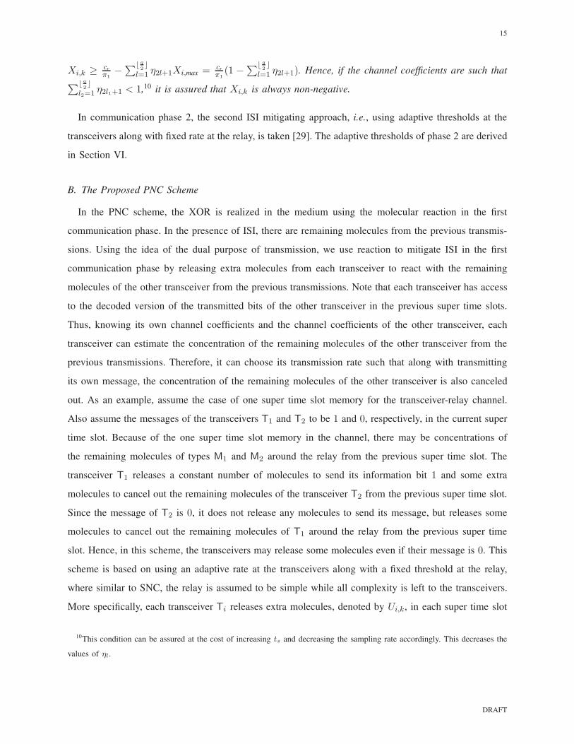
In communication phase 2, the second ISI mitigating approach, i.e., using adaptive thresholds at the
transceivers along with fixed rate at the relay, is taken [29]. The adaptive thresholds of phase 2 are derived
in Section VI.
B. The Proposed PNC Scheme
In the PNC scheme, the XOR is realized in the medium using the molecular reaction in the first
communication phase. In the presence of ISI, there are remaining molecules from the previous transmis-
sions. Using the idea of the dual purpose of transmission, we use reaction to mitigate ISI in the first
communication phase by releasing extra molecules from each transceiver to react with the remaining
molecules of the other transceiver from the previous transmissions. Note that each transceiver has access
to the decoded version of the transmitted bits of the other transceiver in the previous super time slots.
Thus, knowing its own channel coefficients and the channel coefficients of the other transceiver, each
transceiver can estimate the concentration of the remaining molecules of the other transceiver from the
previous transmissions. Therefore, it can choose its transmission rate such that along with transmitting
its own message, the concentration of the remaining molecules of the other transceiver is also canceled
out. As an example, assume the case of one super time slot memory for the transceiver-relay channel.
Also assume the messages of the transceivers T1 and T2 to be 1 and 0, respectively, in the current super
time slot. Because of the one super time slot memory in the channel, there may be concentrations of
the remaining molecules of types M1 and M2 around the relay from the previous super time slot. The
transceiver T1 releases a constant number of molecules to send its information bit 1 and some extra
molecules to cancel out the remaining molecules of the transceiver T2 from the previous super time slot.
Since the message of T2 is 0, it does not release any molecules to send its message, but releases some
molecules to cancel out the remaining molecules of T1 around the relay from the previous super time
slot. Hence, in this scheme, the transceivers may release some molecules even if their message is 0. This
scheme is based on using an adaptive rate at the transceivers along with a fixed threshold at the relay,
where similar to SNC, the relay is assumed to be simple while all complexity is left to the transceivers.
More specifically, each transceiver Ti releases extra molecules, denoted by Ui,k, in each super time slot
10This condition can be assured at the cost of increasing ts and decreasing the sampling rate accordingly. This decreases the
values of ηl.
DRAFT
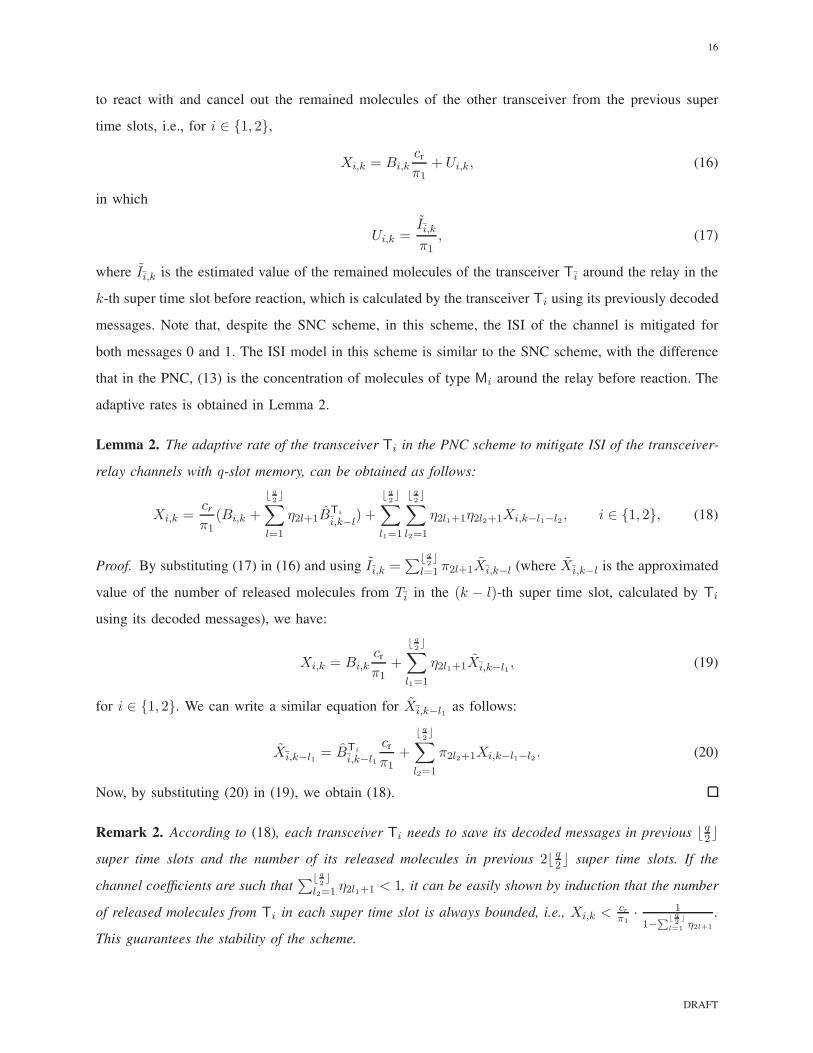
16
to react with and cancel out the remained molecules of the other transceiver from the previous super
time slots, i.e., for i ∈ {1, 2},
Xi,k = Bi,kcr
π1+ Ui,k, (16)
in which
Ui,k =Ii,kπ1
, (17)
where Ii,k is the estimated value of the remained molecules of the transceiver Ti around the relay in the
k-th super time slot before reaction, which is calculated by the transceiver Ti using its previously decoded
messages. Note that, despite the SNC scheme, in this scheme, the ISI of the channel is mitigated for
both messages 0 and 1. The ISI model in this scheme is similar to the SNC scheme, with the difference
that in the PNC, (13) is the concentration of molecules of type Mi around the relay before reaction. The
adaptive rates is obtained in Lemma 2.
Lemma 2. The adaptive rate of the transceiver Ti in the PNC scheme to mitigate ISI of the transceiver-
relay channels with q-slot memory, can be obtained as follows:
Xi,k =cr
π1(Bi,k +
⌊ q
2⌋
∑
l=1
η2l+1BTi
i,k−l) +
⌊ q
2⌋
∑
l1=1
⌊ q
2⌋
∑
l2=1
η2l1+1η2l2+1Xi,k−l1−l2 , i ∈ {1, 2}, (18)
Proof. By substituting (17) in (16) and using Ii,k =∑⌊ q
2⌋
l=1 π2l+1Xi,k−l (where Xi,k−l is the approximated
value of the number of released molecules from Ti in the (k − l)-th super time slot, calculated by Ti
using its decoded messages), we have:
Xi,k = Bi,kcr
π1+
⌊ q
2⌋
∑
l1=1
η2l1+1Xi,k−l1 , (19)
for i ∈ {1, 2}. We can write a similar equation for Xi,k−l1 as follows:
Xi,k−l1 = BTi
i,k−l1
cr
π1+
⌊ q
2⌋
∑
l2=1
π2l2+1Xi,k−l1−l2 . (20)
Now, by substituting (20) in (19), we obtain (18).
Remark 2. According to (18), each transceiver Ti needs to save its decoded messages in previous ⌊ q2⌋
super time slots and the number of its released molecules in previous 2⌊ q2⌋ super time slots. If the
channel coefficients are such that∑⌊ q
2⌋
l2=1 η2l1+1 < 1, it can be easily shown by induction that the number
of released molecules from Ti in each super time slot is always bounded, i.e., Xi,k < cr
π1· 1
1−∑⌊
q2⌋
l=1η2l+1
.
This guarantees the stability of the scheme.
DRAFT

17
Remark 3. In Section VII, for a fair comparison of the SNC and PNC schemes, we choose cSNCr (the cr
used in (11)) and cPNCr (the cr used in (16)), such that 1
2
∑2i=1 X
SNCi,avg = 1
2
∑2i=1 X
PNCi,avg, where XPNC
i,avg and
XSNCi,avg are the average number of the released molecules from the transceiver Ti in the PNC and SNC
schemes, respectively. The average values can be obtained from (14) and (18) by substituting Xi,k and
Xi,k−1 with their average values (XPNCi,avg or XSNC
i,avg), and Bi,k and Bi,k−1 with their average values, 12 ,
as follows:
XSNCi,avg =
cSNCr
π1·
1
2 +∑⌊ q
2⌋
l=1 η2l+1
, XPNCi,avg =
cPNCr
π1·
1
2(1−∑⌊ q
2⌋
l=1 η2l+1), i ∈ {1, 2}. (21)
Hence,
cSNCr
cPNCr
=2 +
∑⌊ q
2⌋
l=1 η2l+1
2(1 −∑⌊ q
2⌋
l=1 η2l+1). (22)
In communication phase 2, similar to SNC, the approach of adapting thresholds at the receivers is
used with the thresholds derived in Section VI.
V. ERROR PERFORMANCE ANALYSIS WITH NO ISI
In this section, we derive the probabilities of error at the transceivers T1 and T2, noted by pe,1 and pe,2,
respectively. Throughout this paper, we consider the average bit error probability (Avg-BEP) as follows:
Avg-BEP =1
2(pe,1 + pe,2). (23)
First, we investigate the error probabilities of the SNC scheme. Then, using a similar approach, we derive
the error probabilities of the proposed PNC scheme. Since the error probability without ISI in the current
super time slot does not depend on the error probabilities of the previous super time slots and is the
same for all super time slots, we drop the index k of the bits and error events in this section.
A. The SNC scheme
In the SNC scheme, as mentioned before, the i-th receptor at the relay decodes Bi (the message of the
transceiver Ti) as BRi . The relay XORs the decoded messages and sends the message BR = BR
1 ⊕ BR2
to the transceivers using XR3 = BRζ3 molecules of type M3. Each transceiver Ti decodes the message
of the relay as BTi
Rand, finds the message sent by the other transceiver as BTi
i= Bi ⊕ BTi
R, i ∈ {1, 2}.
Define Ei as the error event at the transceiver Ti, i.e., BTi
i6= Bi. The probability of the event Ei is
shown by P(Ei) = pe,i. Ei consists of two error events corresponding to two communication phases:
i. ER: B1 ⊕B2 is decoded with error at the relay (BR 6= B1 ⊕B2).
ii. ETi : The i-th transceiver decodes the message of the relay with error (BTi
R6= BR).
The probabilities of the first and second events are shown by P(ER) and P(ETi), respectively. We show
DRAFT

18
the conditioned event {B = b} with {b} for brevity, when it is clear from the context. The total error
probability at the transceiver Ti in terms of P(ER) and P(ETi) is obtained in Lemma 3.
Lemma 3. The total error probability at the transceiver Ti in the SNC scheme can be obtained as
pe,i =1
2
∑
bR∈{0,1}
P(ETi |BR = bR) +1
4
[
1−∑
bR∈{0,1}
P(ETi |BR = bR)]
∑
b1,b2∈{0,1}
P(ER|b1, b2). (24)
Proof. The total error probability at Ti conditioned to B1 = b1 and B2 = b2 can be obtained as
P(Ei|B1 = b1, B2 = b2) = P(BTi
i6= Bi|b1, b2)
=P(BTi
R= BR, BR 6= b1 ⊕ b2|b1, b2) + P(BTi
R6= BR, BR = b1 ⊕ b2|b1, b2)
=P(ER|b1, b2)(
1− P(ETi |BR = b1 ⊕ b2))
+(
1− P(ER|b1, b2))
P(ETi |BR = b1 ⊕ b2), (25)
for i ∈ {1, 2}. By taking average over B1 and B2, the total probability of error at the transceiver Ti can
be easily obtained for i ∈ {1, 2} as (24).
In the following, we compute the error probabilities of the two phases, i.e., P(ER|b1, b2) and P(ETi |BR).
Phase 1: When Ti sends Bi = bi, the average concentration molecules of type Mi at the relay is
Ci = biζπ1. Hence, due to the transparent receiver, the number of counted molecules of type Mi at
the relay, Y Ri , is Poisson(biζπ1vr). The relay uses a threshold τRi to decode Bi: if Yi ≤ τRi , then Bi is
decoded as BRi = 0; otherwise, it is decoded as BR
i = 1.
Lemma 4. For a transparent receiver with no environment noise, the optimum threshold to decode a
message B ∈ {0, 1} with P{B = 0} ≥ P{B = 1},11 which is sent using OOK modulation, is obtained
using the maximum-a-posteriori (MAP) decision rule as τ = 0.
Proof. For a transparent receiver with no environment noise, if Y is the number of counted molecules
at the receiver, we have
P{Y = y|B = 0} = δ[y]. (26)
Using the MAP decision rule to decode B, we have
P{B = 1}P(y|B = 1)1≷0P{B = 0}P(y|B = 0) = P{B = 0}δ[y], (27)
which results in τ = 0, since P{B = 0} ≥ P{B = 1}.
11While assumption of uniform distribution on message bits is common in communication systems, we need this general
condition to obtain the optimum thresholds at the receivers (both at the relay and the transceivers). Note that our assumption
allows for the uniform distribution on message bits.
DRAFT
19
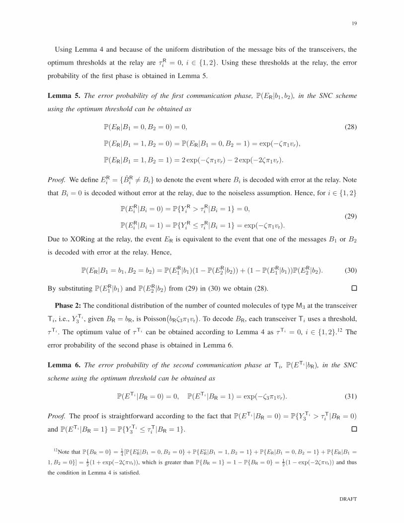
Using Lemma 4 and because of the uniform distribution of the message bits of the transceivers, the
optimum thresholds at the relay are τRi = 0, i ∈ {1, 2}. Using these thresholds at the relay, the error
probability of the first phase is obtained in Lemma 5.
Lemma 5. The error probability of the first communication phase, P(ER|b1, b2), in the SNC scheme
using the optimum threshold can be obtained as
P(ER|B1 = 0, B2 = 0) = 0, (28)
P(ER|B1 = 1, B2 = 0) = P(ER|B1 = 0, B2 = 1) = exp(−ζπ1vr),
P(ER|B1 = 1, B2 = 1) = 2 exp(−ζπ1vr)− 2 exp(−2ζπ1vr).
Proof. We define ERi = {BR
i 6= Bi} to denote the event where Bi is decoded with error at the relay. Note
that Bi = 0 is decoded without error at the relay, due to the noiseless assumption. Hence, for i ∈ {1, 2}
P(ER
i |Bi = 0) = P{Y R
i > τRi |Bi = 1} = 0,
P(ER
i |Bi = 1) = P{Y R
i ≤ τRi |Bi = 1} = exp(−ζπ1vr).
(29)
Due to XORing at the relay, the event ER is equivalent to the event that one of the messages B1 or B2
is decoded with error at the relay. Hence,
P(ER|B1 = b1, B2 = b2) = P(ER
1 |b1)(1− P(ER
2 |b2)) + (1− P(ER
1 |b1))P(ER
2 |b2). (30)
By substituting P(ER1 |b1) and P(ER
2 |b2) from (29) in (30) we obtain (28).
Phase 2: The conditional distribution of the number of counted molecules of type M3 at the transceiver
Ti, i.e., Y Ti
3 , given BR = bR, is Poisson(
bRζ3π1vr
)
. To decode BR, each transceiver Ti uses a threshold,
τTi . The optimum value of τTi can be obtained according to Lemma 4 as τTi = 0, i ∈ {1, 2}.12 The
error probability of the second phase is obtained in Lemma 6.
Lemma 6. The error probability of the second communication phase at Ti, P(ETi |bR), in the SNC
scheme using the optimum threshold can be obtained as
P(ETi |BR = 0) = 0, P(ETi |BR = 1) = exp(−ζ3π1vr). (31)
Proof. The proof is straightforward according to the fact that P(ETi |BR = 0) = P{Y Ti
3 > τTi |BR = 0)
and P(ETi |BR = 1} = P{Y Ti
3 ≤ τTi |BR = 1}.
12Note that P{BR = 0} = 1
4[P{Ec
R|B1 = 0, B2 = 0}+ P{EcR|B1 = 1, B2 = 1}+ P{ER|B1 = 0, B2 = 1} + P{ER|B1 =
1, B2 = 0}] = 1
2(1 + exp(−2ζπvr)), which is greater than P{BR = 1} = 1 − P{BR = 0} = 1
2(1 − exp(−2ζπvr)) and thus
the condition in Lemma 4 is satisfied.
DRAFT

20
Now, by substituting the error probabilities of the two communication phases (from (28) and (31)) in
(24), we obtain pe,i, i ∈ {1, 2}, as
pe,i =1
2exp(−ζ3π1vr) +
1
2[1− exp(−ζ3π1vr)] [2 exp(−ζπ1vr)− exp(−2ζπ1vr)] . (32)
B. The proposed PNC scheme
In the PNC scheme, each transceiver Ti sends its message Bi ∈ {0, 1} to the relay through releasing
Xi = ζBi molecules of type Mi. When both transceivers send the information bit 1, almost all molecules
react with each other and we have a physical-layer XOR. That is, the relay implicitly decodes the
physically made XOR of the messages, B1 ⊕ B2, and sends it to the transceivers through releasing
X3 molecules of type M3. We define an auxiliary variable BRias the part of the message B1 ⊕ B2
which corresponds to Bi. Each receptor i at the relay decodes the message BRi= Bi · (B1 ⊕ B2),
the part of the message B1 ⊕ B2 which corresponds to Bi, as BRi. For BR1
= BR2= 0, the relay
stays silent; otherwise (when BR1= 1 or BR2
= 1), it releases ζ3 molecules of type M3 and hence,
X3 = (BR1+ BR2
)ζ3 = BRζ3. Due to the perfect reaction assumption, BR1and BR2
cannot be 1 at the
same time and thus, X3 ∈ {0, ζ3}. We remark that these notations are used for the ease of error analysis.
In fact, the message sent by the relay (BR) implicitly shows the B1 ⊕B2 and it is realized through BR1
and BR2in our scheme. Furthermore, the system naturally adds up BR1
and BR2, because the encoder
would release molecules when it is stimulated by the active receptor (at most one active receptor exists
in each time slot).
The error events in this scheme are defined similar to the SNC scheme and the total error probability
at the transceiver Ti can be obtained from Lemma 3. Since the second communication phase is the same
in both SNC and PNC schemes, P(ETi |bR) for both schemes can be obtained from Lemma 6. In the
following, we derive the error probability of the first phase.
In phase 1, when both transceivers send the same information bit 1 or 0, the concentrations of molecules
of types 1 and 2 around the relay are C1 = C2 = 0 (thanks to perfect reaction) and when the transceiver
Ti, i ∈ {1, 2}, sends the information bit 1 and the transceiver Ti sends the information bit 0, the
concentrations are Ci = ζπ1 and Ci = 0. Hence, when BRi= bRi
, the average concentration of the
molecule type Mi around the relay is Ci = bRiζπ1, and due to the transparent receiver, the number of
counted molecules of type Mi at the relay, Y Ri , is Poisson(bRi
ζπ1vr). Similar to the SNC scheme, the
relay uses a threshold τRi , to decode BRi. According to Lemma 4, the optimum thresholds are obtained
DRAFT

21
TABLE II: Messages and number of molecules sent by the relay in the proposed PNC scheme
B1 B2 B1 ⊕B2 BR1= B1 · (B1 ⊕B2) BR2
= B2 · (B1 ⊕B2) X3
0 0 0 0 0 0
1 0 1 1 0 BR1ζ3
0 1 1 0 1 BR2ζ3
1 1 0 0 0 0
as τRi = 0, i ∈ {1, 2}.13 Using these thresholds, the error probability of the first phase in the PNC scheme
is obtained in Lemma 7.
Lemma 7. The error probability of the first communication phase, P(ER|b1, b2), in the PNC scheme
using the optimum threshold can be obtained as
P(ER|B1 = 0, B2 = 0) = P(ER|B1 = 1, B2 = 1) = 0, (33)
P(ER|B1 = 1, B2 = 0) = P(ER|B1 = 0, B2 = 1) = exp(−ζπ1vr).
Proof. We define ERias the event {BRi
6= BRi}. Hence, P(ERi
) is the probability of error when BRiis
decoded with error at the i-th receptor of the relay. Since τRi = 0, for i ∈ {1, 2},
P(ERi|BRi
= 0) = 0, P(ERi|BRi
= 1) = exp(−ζπ1vr). (34)
Recall that the number of released molecules of type M3 equals to X3 = 0 when the transceivers send the
same messages and X3 = ζ3 when one of the transceivers send the information bit 1 and the corresponding
receptor at the relay decodes it correctly (see Table II). Thus, when (B1, B2) ∈ {(0, 0), (1, 1)}, BR1and
BR2equal to zero and are decoded without error at the relay. When (B1, B2) = (1, 0), we have BR1
= 1
and BR2= 0. Hence, BR2
is decoded without error at the relay and we get P(ER|B1 = 1, B2 = 0) =
P(ER1|BR1
= 1). Similarly, we get P(ER|B1 = 1, B2 = 0) = P(ER2|BR2
= 1).
Now, by substituting the error probabilities of the two phases from (33) and (31) in (24), we obtain
pe,i =1
2exp(−ζ3π1vr) +
1
2[1− exp(−ζ3π1vr)] exp(−ζπ1vr), (35)
for i ∈ {1, 2}, and thus the Avg-BEP can be obtained from (23).
Remark 4. Comparing (32) and (35), it can be seen that the error probability at each transceiver and
thus the Avg-BEP of the PNC is lower than the SNC since exp(−ζπ1vr) > exp(−2ζπ1vr) and hence,
13Note that here we have, P{BRi= 1} = P{Bi = 1, Bi = 0} = 1
4and P{BRi
= 0} = 1 − P{BRi= 1} = 3
4. Hence,
P{BRi= 1} < P{BRi
= 0} and the condition in Lemma 4 is satisfied.
DRAFT

22
exp(−ζπ1vr) < 2 exp(−ζπ1vr) − exp(−2ζπ1vr). In fact, since P(ER|B1 = 1, B2 = 1) is zero for the
PNC scheme, but it is positive for the SNC scheme, the error probability at the relay is lower for the
PNC scheme. Further, P(ETi |BR = 0) and P(ETi |BR = 1) are equal for both schemes. Thus, according
to (24), the error probability at the transceivers is lower for the PNC scheme.
VI. ERROR PERFORMANCE ANALYSIS IN THE PRESENCE OF ISI
For simplicity of exposition, we assume the transceiver-relay and the relay-transceiver channels to have
unit super time slot memory. In Section VII, we simulate the system for higher channels memories.
A. The SNC scheme
Similar to the no ISI case, from (24), we define two error events in each super time slot corresponding
to each communication phase: (i) ER,k = {BR,k 6= BR,k}, and (ii) ETi
k = {BTi
R,k 6= BR,k}. In the
following, we obtain the error probabilities of both communication phases.
Phase 1: According to (14), the transceiver Ti uses the number of released molecules in the (k−1)-th
super time slot to determine the number of released molecules in the k-th super time slot: if its message
is 1, the transceiver Ti releases some molecules such that the concentration of molecules of type Mi
at the relay will be equal to cr and if its message is 0, it stays silent (concentration of the molecules
of type Mi at the relay will be equal to the concentration of the remained molecules from the previous
super time slot, i.e., Xi,k−1π3). Hence, given Bi,k = bi and Xi,k−1 = x, the average concentration of
molecules of type Mi around the relay is Ci,k = bicr +(1− bi)xπ3 and the number of counted molecules
of type Mi at the relay, Y R
i,k, has a Poisson distribution with parameter Ci,kvr. It is just straightforward
to show from (14) that the probability distribution function (PDF) of Xi,k for i ∈ {1, 2} is as follows:
pXi,k(x) =
∞∑
n=1
(1
2)nδ(x − xn), xn =
cr
π1
n−2∑
l=0
(−η3)l, n ∈ N. (36)
The relay uses MAP decision rule to decode the message of the transceiver Ti, i ∈ {1, 2}, i.e., Bi,k, as
1
2P(yRi,k|Bi,k = 1)
1≷0
1
2P(yRi,k|Bi,k = 0). (37)
Noting that yRi,k conditioned on Bi,k = 0 depends on Xi,k−1, and taking average of P(yRi,k|Bi,k = 0) over
Xi,k−1 results in
P(yRi,k|Bi,k = 1)1≷0
∞∫
0
pXi,k−1(x)P(yRi,k|Bi,k = 0,Xi,k−1 = x)dx. (38)
By substituting pXi,k−1(x) from (36), we obtain the MAP decision rule at the i-th receptor as
(crvr)yR
i,k exp(−crvr)1≷0
∞∑
n=1
(1
2)n(xnπ3vr)
yR
i,k exp(−xnπ3vr). (39)
DRAFT
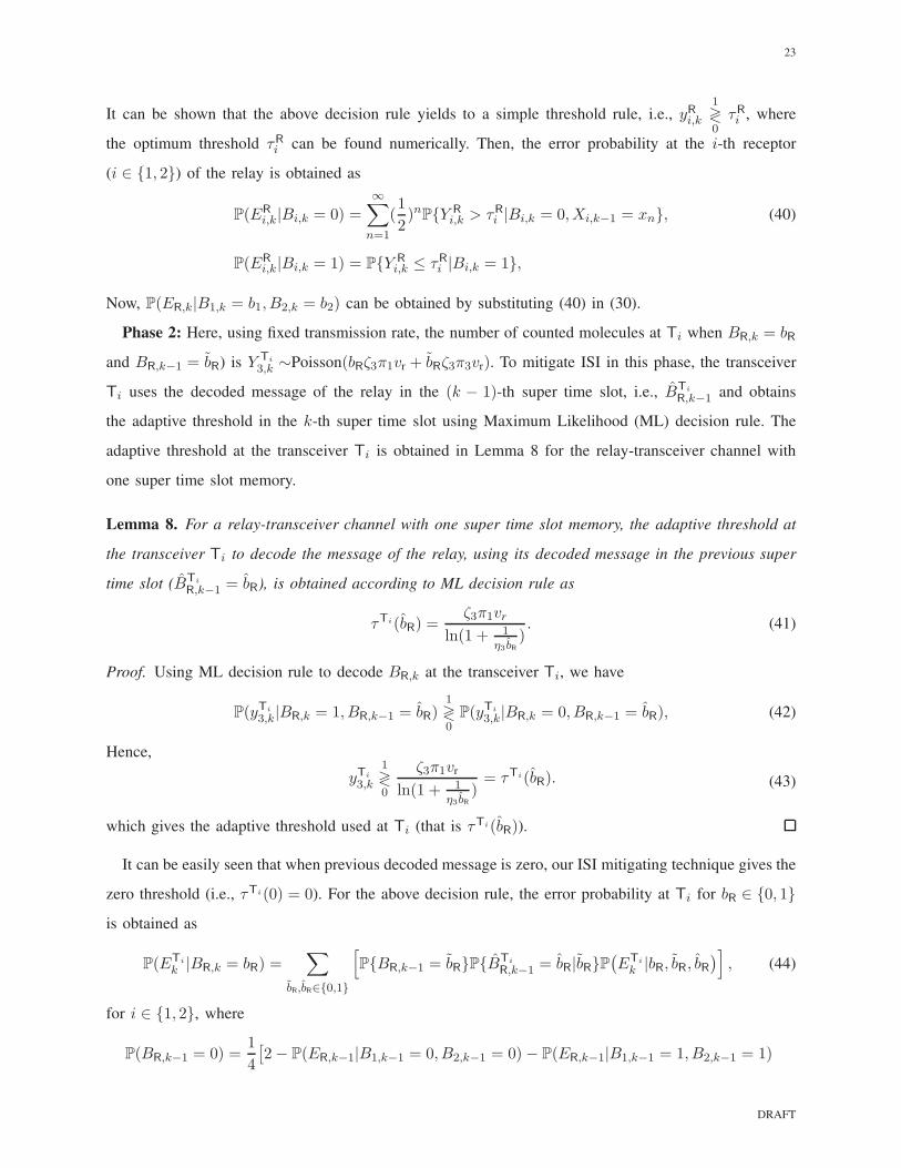
23
It can be shown that the above decision rule yields to a simple threshold rule, i.e., yRi,k1≷0τRi , where
the optimum threshold τRi can be found numerically. Then, the error probability at the i-th receptor
(i ∈ {1, 2}) of the relay is obtained as
P(ER
i,k|Bi,k = 0) =
∞∑
n=1
(1
2)nP{Y R
i,k > τRi |Bi,k = 0,Xi,k−1 = xn}, (40)
P(ER
i,k|Bi,k = 1) = P{Y R
i,k ≤ τRi |Bi,k = 1},
Now, P(ER,k|B1,k = b1, B2,k = b2) can be obtained by substituting (40) in (30).
Phase 2: Here, using fixed transmission rate, the number of counted molecules at Ti when BR,k = bR
and BR,k−1 = bR) is Y Ti
3,k ∼Poisson(bRζ3π1vr + bRζ3π3vr). To mitigate ISI in this phase, the transceiver
Ti uses the decoded message of the relay in the (k − 1)-th super time slot, i.e., BTi
R,k−1 and obtains
the adaptive threshold in the k-th super time slot using Maximum Likelihood (ML) decision rule. The
adaptive threshold at the transceiver Ti is obtained in Lemma 8 for the relay-transceiver channel with
one super time slot memory.
Lemma 8. For a relay-transceiver channel with one super time slot memory, the adaptive threshold at
the transceiver Ti to decode the message of the relay, using its decoded message in the previous super
time slot (BTi
R,k−1 = bR), is obtained according to ML decision rule as
τTi(bR) =ζ3π1vr
ln(1 + 1η3 bR
). (41)
Proof. Using ML decision rule to decode BR,k at the transceiver Ti, we have
P(yTi
3,k|BR,k = 1, BR,k−1 = bR)1≷0P(yTi
3,k|BR,k = 0, BR,k−1 = bR), (42)
Hence,
yTi
3,k
1≷0
ζ3π1vr
ln(1 + 1η3 bR
)= τTi(bR). (43)
which gives the adaptive threshold used at Ti (that is τTi(bR)).
It can be easily seen that when previous decoded message is zero, our ISI mitigating technique gives the
zero threshold (i.e., τTi(0) = 0). For the above decision rule, the error probability at Ti for bR ∈ {0, 1}
is obtained as
P(ETi
k |BR,k = bR) =∑
bR,bR∈{0,1}
[
P{BR,k−1 = bR}P{BTi
R,k−1 = bR|bR}P(
ETi
k |bR, bR, bR)
]
, (44)
for i ∈ {1, 2}, where
P(BR,k−1 = 0) =1
4
[
2− P(ER,k−1|B1,k−1 = 0, B2,k−1 = 0)− P(ER,k−1|B1,k−1 = 1, B2,k−1 = 1)
DRAFT

24
+ P(ER,k−1|B1,k−1 = 0, B2,k−1 = 1) + P(ER,k−1|B1,k−1 = 1, B2,k−1 = 0)]
, (45)
P(BTi
R,k−1 = bR|bR) =
P(ETi
k−1|bR), if bR 6= bR,
1− P(ETi
k−1|bR), if bR = bR,
(46)
and P(
ETi
k |BR,k = 0, bR, bR)
= P{
Y Ti
3,k > τTi(bR)|BR,k = 0, bR}
, P(
ETi
k |BR,k = 1, bR, bR)
= P{
Y Ti
3,k ≤
τTi(bR)|BR,k = 1, bR}
. Hence, P(ETi
k |BR,k = bR) can be obtained recursively from (44). Since we have
two linear equations in (44) with two unknowns, a closed form equation can be easily obtained for
P(ETi
k |BR,k = bR).
Remark 5. (No error (NoE) approximation) The total error probability at the transceiver Ti can be
further simplified assuming that the message of the relay is decoded without error at the transceivers in
the previous super time slot (i.e., we ignore the error propagation). Hence, the error probability of the
second phase can be obtained simply from (44) assuming P(ETi
k−1|bR) = 0, and the total error probability
at the transceiver Ti can be obtained for i ∈ {1, 2} using (25):
pNoEe,i =
1
16
(
(2− u1)2 − u22
)
wi,1 +1
16
(
(2− u2)2 − u21
)
wi,2 +1
4(u1 + u2), (47)
where u1 = P(ER,k|B1,k = 0, B2,k = 0) + P(ER,k|B1,k = 1, B2,k = 1), u2 = P(ER,k|B1,k = 0, B2,k =
1) + P(ER,k|B1,k = 1, B2,k = 0) can be computed from (40) and (30), and
wi,1 = exp(−ζ3π1vr) +
∞∑
l=τTi(1)+1
(ζ3π3vr)l
l!exp(−ζ3π3vr), (48)
wi,2 =
τTi (1)∑
l=0
(ζ3(π1 + π3)vr)l
l!exp(−ζ3(π1 + π3)vr).
This provides a lower bound on the error probability of the SNC scheme as follows: from (24), we have
pe,i = P(ER) +12
(
1− 2P(ER))
[P(ETi |BR = 0) + P(ETi |BR = 1)]; by ignoring the error propagation,
we obtain lower bounds on P(ETi |BR = 0) and P(ETi |BR = 1); now, since P(ER) ≤ 0.5, this is a
lower bound on pe,i.
B. The PNC scheme
Here, the error probability of the second phase is the same as that of the SNC given in (44), with the
difference that P(BR,k−1 = 0) must be computed separately from (45), since the error probabilities of
the first phase are not equal for two schemes. Thus, we only analyze the error probability of the first
phase. According to (18), the transceiver Ti uses the decoded message of the other transceiver in the
(k− 1)-th super time slot (BTi
i,k−1) and the number of its own released molecules in the (k− 2)-th super
time slot (Xi,k−2) to determine the number of released molecules in the k-th super time slot. X1,k−2 and
DRAFT
25
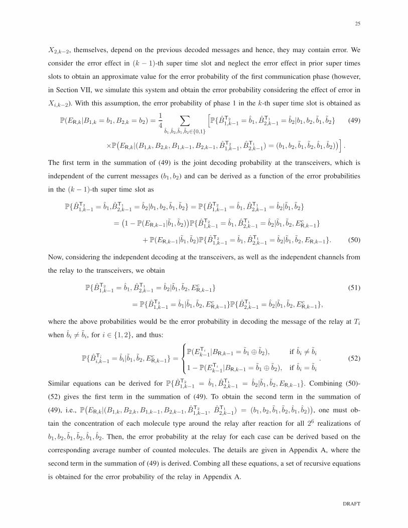
X2,k−2, themselves, depend on the previous decoded messages and hence, they may contain error. We
consider the error effect in (k − 1)-th super time slot and neglect the error effect in prior super times
slots to obtain an approximate value for the error probability of the first communication phase (however,
in Section VII, we simulate this system and obtain the error probability considering the effect of error in
Xi,k−2). With this assumption, the error probability of phase 1 in the k-th super time slot is obtained as
P(ER,k|B1,k = b1, B2,k = b2) =1
4
∑
b1,b2,b1,b2∈{0,1}
[
P{BT2
1,k−1 = b1, BT1
2,k−1 = b2|b1, b2, b1, b2} (49)
×P(
ER,k|(B1,k, B2,k, B1,k−1, B2,k−1, BT2
1,k−1, BT1
2,k−1) = (b1, b2, b1, b2, b1, b2))
]
.
The first term in the summation of (49) is the joint decoding probability at the transceivers, which is
independent of the current messages (b1, b2) and can be derived as a function of the error probabilities
in the (k − 1)-th super time slot as
P{BT2
1,k−1 = b1,BT1
2,k−1 = b2|b1, b2, b1, b2} = P{BT2
1,k−1 = b1, BT1
2,k−1 = b2|b1, b2}
=(
1− P(ER,k−1|b1, b2))
P{BT2
1,k−1 = b1, BT1
2,k−1 = b2|b1, b2, EcR,k−1}
+ P(ER,k−1|b1, b2)P{BT2
1,k−1 = b1, BT1
2,k−1 = b2|b1, b2, ER,k−1}. (50)
Now, considering the independent decoding at the transceivers, as well as the independent channels from
the relay to the transceivers, we obtain
P{BT2
1,k−1 = b1, BT1
2,k−1 = b2|b1, b2, EcR,k−1} (51)
= P{BT2
1,k−1 = b1|b1, b2, EcR,k−1}P{B
T1
2,k−1 = b2|b1, b2, EcR,k−1},
where the above probabilities would be the error probability in decoding the message of the relay at Ti
when bi 6= bi, for i ∈ {1, 2}, and thus:
P{BTi
i,k−1 = bi|b1, b2, EcR,k−1} =
P(ETi
k−1|BR,k−1 = b1 ⊕ b2), if bi 6= bi
1− P(ETi
k−1|BR,k−1 = b1 ⊕ b2), if bi = bi
. (52)
Similar equations can be derived for P{BT2
1,k−1 = b1, BT1
2,k−1 = b2|b1, b2, ER,k−1}. Combining (50)-
(52) gives the first term in the summation of (49). To obtain the second term in the summation of
(49), i.e., P(
ER,k|(B1,k, B2,k, B1,k−1, B2,k−1, BT2
1,k−1, BT1
2,k−1) = (b1, b2, b1, b2, b1, b2))
, one must ob-
tain the concentration of each molecule type around the relay after reaction for all 26 realizations of
b1, b2, b1, b2, b1, b2. Then, the error probability at the relay for each case can be derived based on the
corresponding average number of counted molecules. The details are given in Appendix A, where the
second term in the summation of (49) is derived. Combing all these equations, a set of recursive equations
is obtained for the error probability of the relay in Appendix A.
DRAFT

26
Remark 6. (NoE approximation) To further simplify the error performance results, we consider the
case where there is no error in the decoded messages of the previous super time slots. Then, the error
probability of phase 1 will be equal to the no ISI case, and the error probability of the second phase can
be obtained similar to the SNC scheme. Hence, we obtain the total error probability at the transceiver
Ti as follows:
pNoEe,i =
1
16(4− u2)wi,1 +
1
16(2− u)2wi,2 +
1
4u, (53)
for i ∈ {1, 2}, where u = exp(−ζ1π1vr) + exp(−ζ2π1vr), and wi,1, wi,2 are defined in (48). Note that,
ignoring the error propagation gives lower bounds on the error probabilities of each hop, while the
overall error probability cannot be proved to necessarily be a lower bound. However, in our simulation
results, it is always a lower bound.
VII. SIMULATION AND NUMERICAL RESULTS
In this section, we evaluate the performance of the PNC and SNC schemes in terms of the probability
of error. We consider the parameters D = 10−9 m2/s, d = 250 nm, and vr =43π(50)
3 nm3 (consistent
with prior works [21], [35] ). In the no ISI case, we choose ts = t0 = 10.4167 µs which is the time that
the impulse responses of the channels take their maximum. In the ISI case, we assume t0 = 10.4167 µs
and ts is chosen such that ηq+2 = 0.05. For the simulations, we run the Monte-Carlo simulations for
5×10⁶ transmitted bits (based on uniform distribution). For each bit, we generate a random number using
the distribution of the number of received molecules. Then, using the derived threshold in the receiver,
we decode each transmitted bit, and hereby estimate the bit error probability with bit error rate.
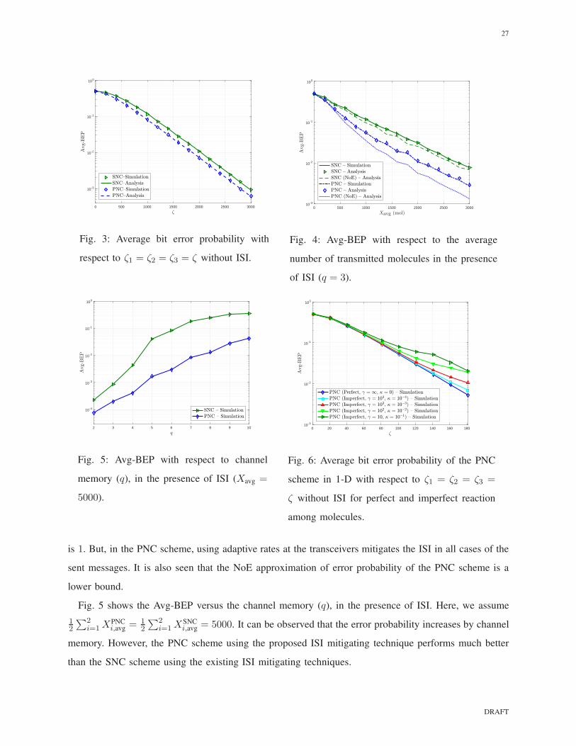
Fig. 3 shows the Avg-BEP versus the number of transmitted molecules from the transceivers and the
relay for information bit 1 (i.e., ζ1 = ζ2 = ζ3 = ζ) for the two schemes without ISI using (23), (35), and
(32) along with the Avg-BEP using simulation. It can be seen that the proposed PNC scheme outperforms
the SNC scheme. This is due to the reduction in the number of the molecules bound to the receptors
(thanks to reaction). Also, the simulations confirm the analytical results.
Fig. 4 shows the Avg-BEP versus the average number of transmitted molecules from the transceivers
and the relay (i.e., 12
∑2i=1 X
PNCi,avg = 1
2
∑2i=1X
SNCi,avg = 1
2ζ3 = Xavg) in the presence of ISI using analysis
and simulation along with the Avg-BEP using NoE approximations given in (53) and (47) for the channels
with memory of 3. It can be seen that the error performance of the SNC scheme, for which we adopt the
existing ISI mitigating techniques, is considerably worse than the error performance of the PNC scheme,
for which we have proposed a reaction-based ISI mitigating technique. The reason is that in the SNC
scheme, using adaptive rate at each transceiver mitigates the ISI only when the message of the transceiver
DRAFT
27
0 500 1000 1500 2000 2500 3000
10 -3
10 -2
10 -1
100
Fig. 3: Average bit error probability with
respect to ζ1 = ζ2 = ζ3 = ζ without ISI.
0 500 1000 1500 2000 2500 300010 -3
10 -2
10 -1
100
Fig. 4: Avg-BEP with respect to the average
number of transmitted molecules in the presence
of ISI (q = 3).
2 3 4 5 6 7 8 9 10
10 -4
10 -3
10 -2
10 -1
100
Fig. 5: Avg-BEP with respect to channel
memory (q), in the presence of ISI (Xavg =
5000).
0 20 40 60 80 100 120 140 160 18010 -3
10 -2
10 -1
100
Fig. 6: Average bit error probability of the PNC
scheme in 1-D with respect to ζ1 = ζ2 = ζ3 =
ζ without ISI for perfect and imperfect reaction
among molecules.
is 1. But, in the PNC scheme, using adaptive rates at the transceivers mitigates the ISI in all cases of the
sent messages. It is also seen that the NoE approximation of error probability of the PNC scheme is a
lower bound.
Fig. 5 shows the Avg-BEP versus the channel memory (q), in the presence of ISI. Here, we assume
12
∑2i=1X
PNCi,avg = 1
2
∑2i=1 X
SNCi,avg = 5000. It can be observed that the error probability increases by channel
memory. However, the PNC scheme using the proposed ISI mitigating technique performs much better
than the SNC scheme using the existing ISI mitigating techniques.
DRAFT
28
In Fig. 6, we consider the effect of imperfect reaction on the error performance of the PNC scheme.
Fig. 6 depicts the Avg-BEP of the PNC scheme without ISI versus ζ1 = ζ2 = ζ3 = ζ , when we
have imperfect reaction among molecules of type M1 and M2. More specifically, we assume a finite
forward reaction rate constant and a positive reverse reaction rate constant among molecules (γ =
10, 102, 103, 104 Molecule−1.m.s−1 and κ = 10−1, 10−2, 10−3, 10−4 s−1, respectively) and solve the
reaction-diffusion equations in (9) for 1-D environment numerically using the finite difference method
(FDM) to obtain the concentration of each molecule type at the relay [38].14 Using the FDM, we discretize
time and space to small sections and approximate derivations with difference equations in each section.
Here, we assumed vr = 30 nm and ts = 31.25 µs. The optimum thresholds are not zero for imperfect
reaction and are obtained using simulation such that the error probability is minimized. It is observed
from this figure that for the considered parameters, by increasing the forward reaction rate constant and
decreasing the reverse reaction rate constant, the average error probability gets closer to that of the PNC
with perfect reaction.
VIII. CONCLUDING REMARKS
In this paper, we proposed the physical-layer network coding (PNC) for molecular communication
(MC) called the reaction-based PNC scheme, where we used different molecule types, reacting with each
other by a fast reversible reaction. Hence, we constructed a physical-layer XOR in this scheme without
requiring an XOR gate at the relay. This results in a simple implementation for the proposed scheme
compared to the straightforward network coding (SNC) scheme. To mitigate the ISI, we also used the
reaction characteristics of the PNC scheme and proposed a reaction-based ISI mitigating technique for
this scheme, where each transceiver using its previously decoded messages, cancels out the ISI of the
other transceiver using the reaction of molecules. Considering the transparent receivers with the signal
dependent noise, we investigated the error probabilities of the straightforward and the proposed network
coding schemes. As expected and confirmed by simulations, the reaction-based scheme decreases the
overall error probability in two-way relay MC, while having less complexity. Further, the proposed ISI
mitigating technique for the PNC scheme has significantly better performance compared to the SNC
scheme in which the existing techniques are applied to each hop. The main reason is that in the SNC,
using adaptive transmission rate at each transceiver, mitigates its own ISI only when its message is 1.
However, in the PNC, using adaptive rates at the transceivers mitigates the ISI for all sent messages. The
14Note that because of the time complexity of the FDM for 3-D environment, to see the effect of imperfect reaction on the
PNC scheme, we simulated the system for 1-D instead of 3-D
DRAFT

29
effect of the imperfect reaction on the error probability of the PNC scheme is considered in simulations
using the finite difference method (FDM).
We have assumed that channel state information (CSI) is known at the transceivers, i.e., the transceivers
know the channel coefficients of both transceivers to the relay channels. This is justified if the nodes have
fixed distance, where the channel coefficients can be computed from the diffusion equation. Studying the
network coding schemes with limited (or no) CSI is an interesting future work. Further, we considered
the deterministic model for our analysis which ignores the channel noise. While in the presence of noise,
the derivations would be much more complex, the methods do not change.
REFERENCES
[1] M. Farahnak-Ghazani, G. Aminian, M. Mirmohseni, A. Gohari, and M. Nasiri-Kenari, “Physical layer network coding in
molecular two-way relay networks,” in 2016 Iran Workshop on Communication and Information Theory (IWCIT), pp. 1–6,
May 2016.
[2] A. Einolghozati, M. Sardari, and F. Fekri, “Relaying in diffusion-based molecular communication,” in Information Theory
Proceedings (ISIT), 2013 IEEE International Symposium on, pp. 1844 – 1848, IEEE, 2013.
[3] B. Alberts, D. Bray, J. Watson, and J. Lewis, Molecular Biology of the Cell. Garland Science, 4 ed., 2002. Available at:
https://www.ncbi.nlm.nih.gov/books/NBK26813/.
[4] A. Gohari, M. Mirmohseni, and M. Nasiri-Kenari, “Information theory of molecular communication: directions and
challenges,” IEEE Transactions on Molecular, Biological and Multi-Scale Communications, vol. 2, pp. 120–142, Dec
2016.
[5] M. Pierobon and I. F. Akyildiz, “Noise analysis in ligand-binding reception for molecular communication in nanonetworks,”
IEEE Transactions on Signal Processing, vol. 59, no. 9, pp. 4168–4182, 2011.
[6] G. Aminian, M. Farahnak-Ghazani, M. Mirmohseni, M. Nasiri-Kenari, and F. Fekri, “On the capacity of point-to-point
and multiple-access molecular communications with ligand-receptors,” IEEE Transactions on Molecular, Biological and
Multi-Scale Communications, vol. 1, no. 4, pp. 331–346, 2016.
[7] C. T. Chou, “A markovian approach to the optimal demodulation of diffusion-based molecular communication networks,”
IEEE Transactions on Communications, vol. 63, no. 10, pp. 3728–3743, 2015.
[8] C. T. Chou, “Impact of receiver reaction mechanisms on the performance of molecular communication networks,” IEEE
Transactions on Nanotechnology, vol. 14, no. 2, pp. 304–317, 2015.
[9] B. Nazer and M. Gastpar, “Computation over multiple-access channels,” IEEE Transactions on information theory, vol. 53,
no. 10, pp. 3498–3516, 2007.
[10] M. Goldenbaum and S. Stanczak, “Robust analog function computation via wireless multiple-access channels,” IEEE
Transactions on Communications, vol. 61, no. 9, pp. 3863–3877, 2013.
[11] S. Limmer and S. Stanczak, “On ℓp-norm computation over multiple-access channels,” in Information Theory Workshop
(ITW), 2014 IEEE, pp. 351–355, IEEE, 2014.
[12] O. Abari, H. Rahul, and D. Katabi, “Over-the-air function computation in sensor networks,” arXiv preprint
arXiv:1612.02307, 2016.
[13] S. C. Liew, S. Zhang, and L. Lu, “Physical-layer network coding: Tutorial, survey, and beyond,” Physical Communication,
vol. 6, pp. 4–42, 2013.
DRAFT

30
[14] M. Samoilov, A. Arkin, and J. Ross, “Signal processing by simple chemical systems,” The Journal of Physical Chemistry
A, vol. 106, no. 43, pp. 10205–10221, 2002.
[15] C. Kuttler, Reaction-Diffusion Equations and Applications. Munich, Germany: Technische Univ. Munchen, 2011.
[16] N. Farsad and A. Goldsmith, “A novel molecular communication system using acids, bases and hydrogen ions,” Signal
Processing Advances in Wireless Communications (SPAWC), 2016 IEEE 17th International Workshop on, 2016.
[17] A. Noel, K. C. Cheung, and R. Schober, “Improving receiver performance of diffusive molecular communication with
enzymes,” IEEE Transactions on NanoBioscience, vol. 13, no. 1, pp. 31–43, 2014.
[18] Y. Cho, B. Yilmaz, W. Guo, and C.-B. Chae, “Effective enzyme deployment for degradation of interference molecules in
molecular communication,” in IEEE WCNC 2017 Conference Proceedings, IEEE, 2017.
[19] T. Nakano, T. Suda, and M. J. Moore, “Molecular communication through biological pattern formation,” in Global
Communications Conference (GLOBECOM), 2015 IEEE, pp. 1–7, IEEE, 2015.
[20] S. Wang, W. Guo, and M. D. McDonnell, “Transmit pulse shaping for molecular communications,” in Computer
Communications Workshops (INFOCOM WKSHPS), 2014 IEEE Conference on, pp. 209–210, IEEE, 2014.
[21] R. Mosayebi, A. Gohari, M. Mirmohseni, and M. N. Kenari, “Type based sign modulation and its application for isi
mitigation in molecular communication,” IEEE Transactions on Communications, vol. PP, no. 99, pp. 1–1, 2017.
[22] T. Nakano and J. Shuai, “Repeater design and modeling for molecular communication networks,” in Computer Communi-
cations Workshops (INFOCOM WKSHPS), 2011 IEEE Conference on, pp. 501–506, IEEE, 2011.
[23] D. K. Karig, P. Siuti, R. D. Dar, S. T. Retterer, M. J. Doktycz, and M. L. Simpson, “Model for biological communication
in a nanofabricated cell-mimic driven by stochastic resonance,” Nano communication networks, vol. 2, no. 1, pp. 39–49,
2011.
[24] S. C. Liew, S. Zhang, and L. Lu, “Physical-layer network coding: Tutorial, survey, and beyond,” Physical Communication,
vol. 6, pp. 4–42, 2013.
[25] B. D. Unluturk, D. Malak, and O. B. Akan, “Rate-delay tradeoff with network coding in molecular nanonetworks,”
Nanotechnology, IEEE transactions on, vol. 12, no. 2, pp. 120–128, 2013.
[26] A. Aijaz, H. Aghvami, and M. R. Nakhai, “On error performance of network coding in diffusion-based molecular
nanonetworks,” Nanotechnology, IEEE transactions on, vol. 13, no. 5, pp. 871–874, 2014.
[27] A. Credi, V. Balzani, S. J. Langford, and J. F. Stoddart, “Logic operations at the molecular level. an xor gate based on a
molecular machine,” Journal of the American Chemical Society, vol. 119, no. 11, pp. 2679–2681, 1997.
[28] K. Oishi and E. Klavins, “Biomolecular implementation of linear i/o systems,” IET Systems Biology, vol. 5, no. 4, pp. 252
– 260, 2011.
[29] R. Mosayebi, H. Arjmandi, A. Gohari, M. Nasiri-Kenari, and U. Mitra, “Receivers for diffusion-based molecular
communication: Exploiting memory and sampling rate,” IEEE Journal on Selected Areas in Communications, vol. 32,
no. 12, pp. 2368 – 2380, 2014.
[30] M. Movahednasab, M. Soleimanifar, A. Gohari, M. Nasiri-Kenari, and U. Mitra, “Adaptive transmission rate with a fixed
threshold decoder for diffusion-based molecular communication,” IEEE Transactions on Communications, vol. 64, no. 1,
pp. 236 – 248, 2015.
[31] A. Ahmadzadeh, A. Noel, and R. Schober, “Analysis and design of two-hop diffusion-based molecular communication
networks,” in Global Communications Conference (GLOBECOM), pp. 2820–2825, IEEE, 2014.
[32] M. Pierobon and I. F. Akyildiz, “A physical end-to-end model for molecular communication in nanonetworks,” Nanotech-
nology, IEEE transactions on, vol. 28, no. 4, pp. 871–874, 2010.
DRAFT

31
[33] M. Pierobon and I. F. Akyildiz, “Diffusion-based noise analysis for molecular communication in nanonetworks,” IEEE
Transactions on Signal Processing, vol. 59, no. 6, pp. 2532 – 2547, 2011.
[34] D. Schnoerr, R. Grima, and G. Sanguinetti, “Cox process representation and inference for stochastic reactiondiffusion
processes,” Nature Communications, vol. 7, 2016.
[35] V. Jamali, A. Noel, R. Schober, and A. Goldsmith, “Diffusive molecular communications with reactive signaling,” arXiv
preprint arXiv:1711.00131, 2017.
[36] H. Arjmandi, G. Aminian, A. Gohari, M. Nasiri-Kenari, and U. Mitra, “Capacity of diffusion based molecular communi-
cation networks over lti-poisson channels,” IEEE Transactions on Molecular, Biological and Multi-Scale Communications,
vol. 1, no. 2, pp. 188–201, 2014.
[37] I. Llatser, A. Cabellos-Aparicio, M. Pierobon, and E. Alarcon, “Detection techniques for diffusion-based molecular
communication,” IEEE Journal on Selected Areas in Communications, vol. 31, no. 12, pp. 726–734, 2013.
[38] R. J. LeVeque, Finite difference methods for ordinary and partial differential equations: Steady-state and time-dependent
problems. SIAM, 2007.
APPENDIX A
ERROR PROBABILITY OF PHASE 1 IN THE PROPOSED PNC SCHEME IN THE PRESENCE OF ISI
Consider the set of all 16 cases of the sent and decoded messages of the transceivers in the previous
super time slot (i.e., the set A = {(b1, b2, b1, b2)|b1, b2, b1, b2 ∈ {0, 1}}). We partition A into 5 subsets
shown by Ag, g = 1, ..., 5 (see Table III), based on the same error probability at the relay. In fact, in each
subset (group), the concentration of molecules (of each type) around the relay is the same after reaction
and thus the error probability is the same. Therefore, we rewrite the error probability at the relay, given
in (49), as
P(ER,k|B1,k = b1, B2,k = b2) =1
4
9∑
g=1
fgpg(b1, b2), (54)
where fg =∑
(b1,b2,b1,b2)∈AgP{BT2
1,k−1 = b1, BT1
2,k−1 = b2|b1, b2}, in which P{BT2
1,k−1 = b1, BT1
2,k−1 =
b2|b1, b2} is given in (50), and
pg(b1, b2) = P(ER,k|B1,k = b1, B2,k = b2, (B1,k−1, B2,k−1, BT2
1,k−1, BT1
2,k−1) ∈ Ag).
According to (18), the concentration of molecule type M1 before reaction is cr · (B1,k + η3BT1
2,k−1 +
η3B1,k−1) + η23 · (crBT1
2,k−2 +X1,k−2π1 +X1,k−3π3). The concentration of M2 before reaction is similar.
Assuming only the error in decoding the message of the previous super time slot, we have
C1,k = max{0,[
B1,k −B2,k + η3 · (B1,k−1 − BT2
1,k−1)− η3 · (B2,k−1 − BT1
2,k−1)]
cr},
and C2,k can be obtained similarly (see Table III).
We assume the fixed thresholds at the relay as τR1 = τR2 = 0. For group 1, since all interference is
canceled out, the probability of error at the relay is equal to the no ISI case (obtained in (33)). For group
DRAFT
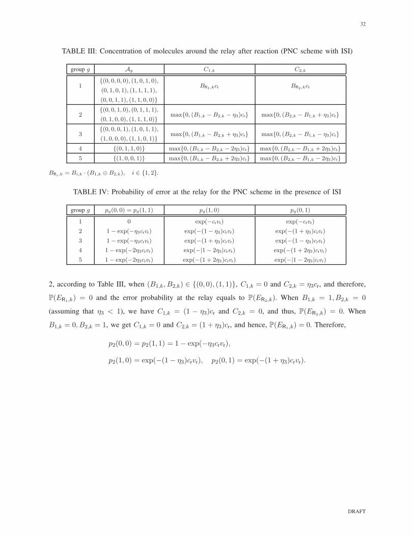
32
TABLE III: Concentration of molecules around the relay after reaction (PNC scheme with ISI)
group g Ag C1,k C2,k
1{(0, 0, 0, 0), (1, 0, 1, 0),
BR1,kcr BR2,kcr(0, 1, 0, 1), (1, 1, 1, 1),
(0, 0, 1, 1), (1, 1, 0, 0)}
2{(0, 0, 1, 0), (0, 1, 1, 1),
max{0, (B1,k −B2,k − η3)cr} max{0, (B2,k −B1,k + η3)cr}(0, 1, 0, 0), (1, 1, 1, 0)}
3{(0, 0, 0, 1), (1, 0, 1, 1),
max{0, (B1,k −B2,k + η3)cr} max{0, (B2,k −B1,k − η3)cr}(1, 0, 0, 0), (1, 1, 0, 1)}
4 {(0, 1, 1, 0)} max{0, (B1,k −B2,k − 2η3)cr} max{0, (B2,k −B1,k + 2η3)cr}
5 {(1, 0, 0, 1)} max{0, (B1,k −B2,k + 2η3)cr} max{0, (B2,k −B1,k − 2η3)cr}
BRi,k = Bi,k · (B1,k ⊕B2,k), i ∈ {1, 2}.
TABLE IV: Probability of error at the relay for the PNC scheme in the presence of ISI
group g pg(0, 0) = pg(1, 1) pg(1, 0) pg(0, 1)
1 0 exp(−crvr) exp(−crvr)
2 1− exp(−η3crvr) exp(−(1− η3)crvr) exp(−(1 + η3)crvr)
3 1− exp(−η3crvr) exp(−(1 + η3)crvr) exp(−(1− η3)crvr)
4 1− exp(−2η3crvr) exp(−|1− 2η3|crvr) exp(−(1 + 2η3)crvr)
5 1− exp(−2η3crvr) exp(−(1 + 2η3)crvr) exp(−|1− 2η3|crvr)
2, according to Table III, when (B1,k, B2,k) ∈ {(0, 0), (1, 1)}, C1,k = 0 and C2,k = η3cr, and therefore,
P(ER1,k) = 0 and the error probability at the relay equals to P(ER2,k). When B1,k = 1, B2,k = 0
(assuming that η3 < 1), we have C1,k = (1 − η3)cr and C2,k = 0, and thus, P(ER2,k) = 0. When
B1,k = 0, B2,k = 1, we get C1,k = 0 and C2,k = (1 + η3)cr, and hence, P(ER1,k) = 0. Therefore,
p2(0, 0) = p2(1, 1) = 1− exp(−η3crvr),
p2(1, 0) = exp(−(1− η3)crvr), p2(0, 1) = exp(−(1 + η3)crvr).
DRAFT