on electromagnetic coil impedance - mfpt
TRANSCRIPT
1
THERMAL DEGRADATION OF POLYIMIDE INSULATION AND ITS EFFECTON ELECTROMAGNETIC COIL IMPEDANCE
N. Jordan Jameson, Michael H. Azarian, and Michael PechtCenter for Advanced Life Cycle Engineering (CALCE)
Building 89, Room 1100CUniversity of Maryland, College Park, MD 20742
Telephone: (301) [email protected]
Abstract: The failure of insulation in electromagnetic coils is a significant cause of coilfailure and can have severe implications for the system in which the coil is used.Impedance monitoring of coils has emerged as a promising avenue for evaluating theinsulation health of electromagnetic coils in-situ. Due to its excellent mechanicalproperties and ability to endure high temperatures, polyimide is widely used as aninsulator in the electromagnetic coil manufacturing industry. However, little informationis known about the electrical behavior of polyimide insulation when subjected to thevariety of stresses experienced when used as electromagnetic coil insulation, castinguncertainty on the use of impedance monitoring when monitoring polyimide insulationhealth. This paper presents an experimental analysis of how the insulation electricalparameters evolve over time, and their consequent effect on the coil impedance spectrum,thus providing useful empirical evidence for impedance monitoring for electromagneticcoil insulation health monitoring.
Keywords: Condition monitoring, electromagnetic coil insulation, insulation healthmonitoring, impedance measurement, insulation capacitance, insulation resistance,polyimide thermal degradation
Introduction: Electromagnetic coils are used ubiquitously in a variety of industries andindustrial applications, including electric motors, solenoid valves, and transformers.Studies have shown that between one-quarter [1], [2] and one-third [3] of motor failuresare due to failures in the insulation. A study of U.S. nuclear power plants [4] showed thatover 50% of solenoid valve failures originated with failures in the electromagnetic coil(e.g., coil opens or coil shorts).
There has been much work addressing the problem of insulation health monitoring inmachinery. In 2004, Stone et al. [5] released a book that is a standard reference forinsulation used in rotating machinery. In it, the available methods of diagnostics forinsulation were discussed. For in-situ insulation health monitoring, the available methodsare partial discharge testing or particulate measurement (i.e., smoke detector) [6], [7].However, many machines, such as low-voltage motors or solenoid-operated valves,operate at voltages that do not induce partial discharge (or induce such low levels as to beunmeasurable). Offline methods include the measurement of the dissipation factor,

2
insulation capacitance, polarization index, insulation resistance, insulation power factor,and offline partial discharge. A common theme for the offline methods discussed is directaccess to the insulation. In other words, in order to measure the insulation capacitance,for example, one must have the ability to place electrodes outside the insulation, in effectusing the insulation as a dielectric between the inner conductor and the outer electrodes.This is not practical for most coils, since measurement of these parameters requiresdisassembly of the system in which the coil is used. Hence, it is necessary to find amethod that can detect insulation degradation and does not rely on these traditionalmethods.
Early efforts at using coil terminal impedance as an insulation health monitoring featurewere outlined in patents from Kendig and Rogovin [8], [9]. The authors did not discloseany quantitative analyses of their proposal, nor did they publish any technical papers; itwas an idea without a technical foundation. In 2006, Werynski et al. [10] asserted that theimpedance resonant frequency could be used as a feature for coil insulation healthmonitoring. Their work was followed in 2007 and 2009 by Perisse et al. [11], [12], and in2013 by Savin et al. [13]. These studies showed that changes in the insulation capacitancecause increases in impedance resonant frequency. The drawbacks of their work are asfollows. First, the aging processes were based upon a uniform temperature in the coilsince the coils were aged in a high temperature oven. Second, insulation resistance wasnot studied, but Younsi et al. [14] showed that insulation resistance can play a significantrole in understanding the aging condition of electromagnetic coil insulation.
Polyimide, a common insulation material used in electromagnetic coils, is a polymerconstructed of imide monomers, which consist of two acyl groups bound to a nitrogen.The chemical structure of “Kapton”, a classic polyimide, is shown in Figure 1. The highresistance of polyimide to thermal degradation and its high mechanical strength leads todiverse applications including high temperature fuel cells, liquid crystal alignments, andmagnet wire insulation for use in electromagnetic coils [15], [16]. Polyimide insulation isgiven a 240 °C temperature rating, which means that the insulation is expected to survivefor 20,000 hours (about 2.3 years) at 240 °C before experiencing electrical breakdown,according to ASTM D2307 [17]. Previous studies of polyimide aging [18]–[20] onlyexamined films (1.5 < thickness < 125 m) of polyimide under various degradationmechanisms (thermal, radiation, saline exposure). The results from these studies aremixed and inconsistent. Further, none of these studies examined the mechanical stressesthat would be present when polyimide is applied as an electromagnetic coil insulator (dueto Joule heating and the resulting expansion of the conductor). Moreover, the ASTMstandard does not address the mechanical stress that the magnet wire will experiencewhen applied in electromagnetic coils.
In this paper, dual-wound coils constructed using polyimide insulation are aged usingJoule heating effects from applied power, which is a more realistic aging condition thanthe uniform temperature aging provided by an oven. Further, the coil impedance, theinsulation impedance, and the insulation resistance are measured to provide insight intothe aging process of polyimide insulation. The experiments provide data and features thatcan be incorporated into electromagnetic coil insulation health monitoring schemes.

3
Figure 1: Chemical structure of “Kapton” polyimide
Experimental Setup: Dual-wound electromagnetic coils were manufactured byMagnecomp, Inc. (South Carolina, USA), as shown in Figure 2 (a). The parallel magnetwires were wound on a rectangular Pyroglass bobbin. An example of this windingarrangement (though not a replica of the arrangement of the experimental coils) isillustrated in Figure 2 (b), where the base numbers indicate the turn number and thesuperscript numbers indicate the two parallel windings of magnet wire. Each winding had230 turns of AWG 27 (conductor diameter of 361 m 3 m) of Heavy Allex®polyimide insulation. This produced 7 layers of parallel windings, and each winding hada DC resistance of about 2.44 .
(a) (b)Figure 2: Dual-wound coil (a) received units; and (b) winding arrangement illustration.
In order to age the insulation in a manner closely resembling the stresses that would belikely in an application condition, one of the parallel windings was powered to producean average internal temperature of 200 °C. This temperature was determined using thetemperature-resistance relationship as shown in (1), where = 0.00393/°C for copper,and and are reference resistance and temperature, respectively. The final averagetemperature of the coil is given by ( ) and the final resistance is given by .Generally, the required voltage was between 7.7 and 7.8 V, and after the transientbehavior settled, the current was between 1.8 and 1.85 A.( ) = 1 + − 1 (1)
The coils were removed from the power periodically and three measurements wereperformed. First, the terminal impedance of one of the windings was measured using an

4
Agilent E4980A LCR meter at 501 distinct frequencies over the frequency range ∈[20, 2 6] Hz with a 500 mV rms signal. This is illustrated for a single winding in Figure3 (a). Second, the impedance of the insulation was measured using an Agilent E4980ALCR meter at 201 distinct frequencies in the frequency range ∈ [20, 2 6] Hz with a1 V rms signal. This measurement was performed by shorting the terminals of eachwinding as illustrated in Figure 3 (b), which allowed the electric field to be directedthrough the insulation only. Third, the response of the insulation to a step application of100 V was measured, allowing for measurement of DC resistance characteristics of theinsulation. This measurement was performed with the coil windings in the same setup asfor the insulation impedance. For this measurement, a 100 VDC potential was placedacross the insulation and held for 20 minutes, while the current was sampled once persecond.
(a) (b)Figure 3: Measurement setup for (a) winding terminal impedance; and (b) insulation
impedance and resistance.
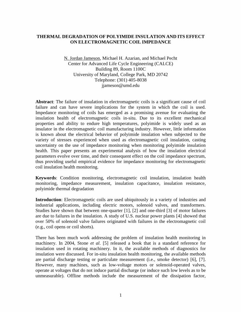
Experimental Results: Impedance is a complex-valued variable, which means it can berepresented in polar form, = | | , or Cartesian form, = ℜ{ } + ℑ{ } = + ,where = √−1. In Cartesian form, the real part is referred to as resistance (not to beconfused with DC resistance), and the imaginary part is referred to as reactance.Reactance, the imaginary part of impedance, can be further broken into inductivereactance, = , and capacitive reactance, = −( ) , such that = ℑ{ } =+ , where = 2 is angular frequency in rad/s (and is frequency in Hz). Sinceany given reactance measurement is either positive or negative, when > 0, the totalreactance is said to be inductive, and when < 0, the total reactance is said to becapacitive. The impedance spectra, shown in Cartesian form, for the one of the windingsover 1103 hours of aging is shown in Figure 4. The resulting increase in the resonantfrequency (the frequency where reactance crosses zero) was reproduced in the othersamples.
The insulation impedance measurements can also be split into real and imaginary parts.In these measurements, reactance was negative (capacitive) over the entire frequencyrange, ∈ [20, 2 6] Hz. Therefore, each reactance measurement was converted intocapacitance using the relationship = −( ) . As can be seen in Figure 5, theinsulation capacitance (at 100 kHz) decreased over the aging period. This behavior wasreplicated in all three samples. It must be noted that the samples aging period was limited
5
by the life of the terminals. Since the terminals are made of magnet wire, the mechanicalstresses introduced by bending caused the terminals to fail prior to the polyimideinsulation. Nevertheless, the aging trend of the insulation is clear and repeatable over thethree samples shown. In one of the samples, there is an increase in the capacitancebetween about 450 hours and 620 hours. This is a partial recovery after the coil wasremoved from thermal stress for 1 week. Hence, the insulation degradation process, asreflected in the electrical parameter measurement, is at least partially reversible.However, after being reconnected to power, the capacitance not only returned to itsprevious value, but the trend continued downward.
Figure 4: Resistance (above) and reactance (below) spectra of one coil winding over thecourse of an experiment (1172 hours).
The analysis of the insulation current was performed as follows. First, the insulationcurrent of healthy insulation was measured over an extended period of time, in order toallow the current to settle. This was done by placing 100 VDC across the insulation, andmeasuring the resulting current. The initial insulation current measurements for two coilsare shown in Figure 6. One coil was measured for about 8.3 hours with currentmeasurements taken every 3 seconds and the other for 13.8 hours with currentmeasurements taken every 5 seconds. Then, in order to measure the effect of aging on theinsulation resistance, the current was sampled every 1 second for 20 minutes. Theseresults are shown in Figure 7 and Figure 8. (For the insulation current measurements,only two samples were available due to experimental complications.)
101 102 103 104 105 106 107
Frequency (Hz)
100
101
102
103
104
105
Res
ista
nce
()
101 102 103 104 105 106 107
Frequency (Hz)
-105-104-103-102-101
0 101 102 103 104 105
Rea
ctan
ce(
)
Initial resonance: 752.6 kHzTime increasing
Time increasing

6
Figure 5: Change in polyimide insulation capacitance as a result of thermal aging at anaverage coil temperature of 200 °C. The line colors and markers correspond to three
different coils.
Figure 6: Polyimide insulation current measurements for new (healthy) insulation. Thetwo colors and markers represent two different coils.
The relationship between the polarization current and the charging time can be expressedusing the Curie-von Schweidler “universal law” for dielectrics [21]–[25] as shown in (2),where ( ) is the polarization current at charging time, , and 0 < < 1 is the powerlaw exponent.
0 500 1000 1500Aging time (hr)
3.5
4
4.5
5
Cap
acita
nce
(nF)
at10
0kH
z
10-3 10-2 10-1 100 101
Charging time (hr)
10-15
10-14
10-13
10-12
10-11
10-10
10-9
10-8
Cur
rent
(A)
Insulation measurements from two different healthy coils

7
( ) ∝ (2)
The curves shown in Figure 6 clearly show this behavior, with the current settling to aconstant value such that the total current is as expressed in (3).( ) = + (3)
In (3), is the coefficient of proportionality, is the steady-state (or conduction) current,and −1 < < 0 is the power law decay of the polarization current. The curve (3) can befit to the data using a robust non-linear least squares algorithm. The robustness in thealgorithm ensures that the adjustments to the function are less sensitive to outliers in thedata. In this work, the least absolute residual (LAR) method for robust regression wasused, which minimizes the absolute value of the residual instead of minimizing the squareof the residual. Therefore, the extreme values have a lesser influence on the fit. Someinsulation current measurements are shown in Figure 7. The measurement procedure wasaltered after the first two measurements to begin the current measurements at 1 second asopposed to 3 seconds. This is the reason for the difference in the starting times for thedata.
Figure 7: Measurements of insulation current versus charging time at 100 VDC as theinsulation aged at an average coil temperature of 200 °C. The lines are drawn over the
data and are shown in the same color as the raw data.
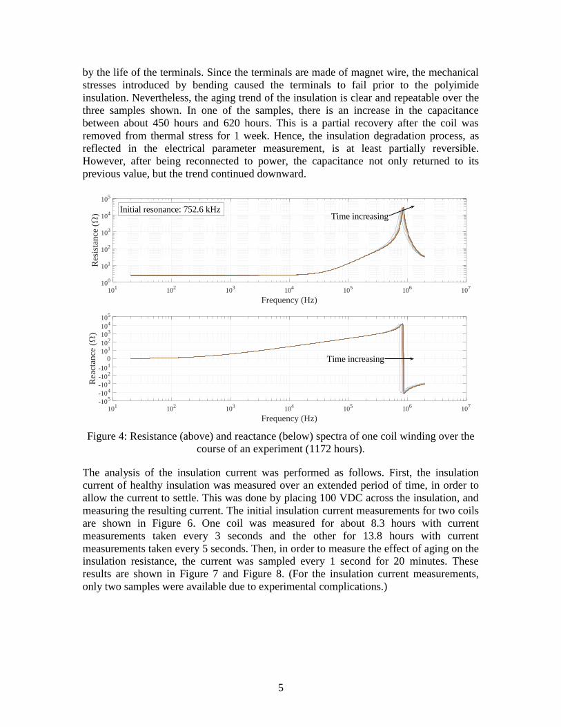
It is clear that as the insulation is aged, the insulation resistance changes. In fact, from thefirst measurement to 16.76 hours of aging, there is a significant decrease in the insulationresistance. In order to illustrate how the insulation resistance changed for two samples asthe insulation aged, the regression fit parameters are shown in Figure 8. The data appearsto be agree between the two samples for the parameters ( ) and ( ), whereas there are
10-1 100 101
100 V charging time (min)
10-12
10-11
10-10
10-9
10-8
Cur
rent
(A)
016.7594
205.464
467.016
659.866
874.051
1065.27
Agi
ngtim
e(h
r)
8
large differences in the parameter ( ) between the two samples. The values of ( )show that the conduction current of the insulation increased over the aging period, orequivalently, the resistance of the insulation decreased as the insulation aged.
Figure 8: Evolution of regression fit of the polarization current as the insulation aged atan average coil temperature of 200 °C. The marker styles and colors correspond to two
different coils.
Terminal impedance data analysis: Previous work [26]–[28] showed that not only doterminal impedance measurements capture changes in the insulation, but there arefrequencies within the impedance spectrum that capture the insulation degradationinformation better than others. To explore this effect in the coils studied in this paper, aSpearman correlation spectrum was constructed. The Spearman correlation coefficient for
samples, , is computed by first converting the raw data into ranked variablesand , then forming the distance measure = − .= 1 − 6( − 1) (4)
The Spearman correlation coefficient is a measure of linear and nonlinear monotoniccorrelation [29], and hence, is more general that Pearson correlation, which onlymeasures linear correlation. The Spearman correlation coefficient was computed usingthe vector of time entries when the coil was removed from power and measured, and thetime series of each impedance measurements at each frequency. This resulted in a vectorthat is the same length as the number of frequencies, = 501, where each entry is aSpearman correlation coefficient quantifying the degree of monotonicity of any givenimpedance measurement at a particular frequency over the degradation time period. Thus,the impedance at each frequency is assessed as a potential health indicator independentlyof the other frequencies.
0 200 400 600 800 1000 120010-11
10-10
10-9
10-8
Mod
elpa
ram
eter
,a(t
)
0 200 400 600 800 1000 1200
Aging time (hr)
-1
-0.95
-0.9
-0.85
-0.8
-0.75
-0.7
-0.65
-0.6
Mod
elpa
ram
eter
,b(t
)
0 200 400 600 800 1000 120010-12
10-11
10-10
10-9
Mod
elpa
ram
eter
,c(t
)

9
The Spearman correlation spectra show the differences in behavior of resistance (ℜ{ })and reactance (ℑ{ }) as the coils aged. In general, there is significant agreement amongthe reactance Spearman spectra, with root mean square (RMS) difference values of0.0905, 0.1052, and 0.0941 between the three curves. The resistance Spearman spectrahave much larger RMS difference values of 0.6898, 0.3589, and 0.7331 between the threecurves.
Figure 9: Resistance (left) and reactance (right) Spearman correlation spectrum for 3 coilsamples aged at an average coil temperature of 200 °C. The line colors and markers
correspond to three different coils aged for different lengths of time.
Consider the time series of reactance at = 604 kHz (one of the minimum points in thethree reactance Spearman spectra) and = 853.2 kHz (the maxima of the three reactanceSpearman spectra) as shown in Figure 10. The “recovery” in one of the coils (asmentioned with the capacitance measurements) is visible between 450 and 620 hours.Similarly, consider the resistance (i.e., ℜ{ }) at = 778.1 kHz and = 1.262 MHz asshown in Figure 11.
Figure 10: Change in reactance at = 604 kHz (left) and = 853.2 kHz (right) over theaging period for three coils. The line colors and markers correspond to three different
coils.
0 500 1000 1500Aging time (hr)
2600
2800
3000
3200
3400
3600
3800
4000
Rea
ctan
ce(
)at
604
kHz
0 500 1000 1500Aging time (hr)
-1.5
-1
-0.5
0
0.5
1
1.5
Rea
ctan
ce(
)at
853.
2kH
z
104
10
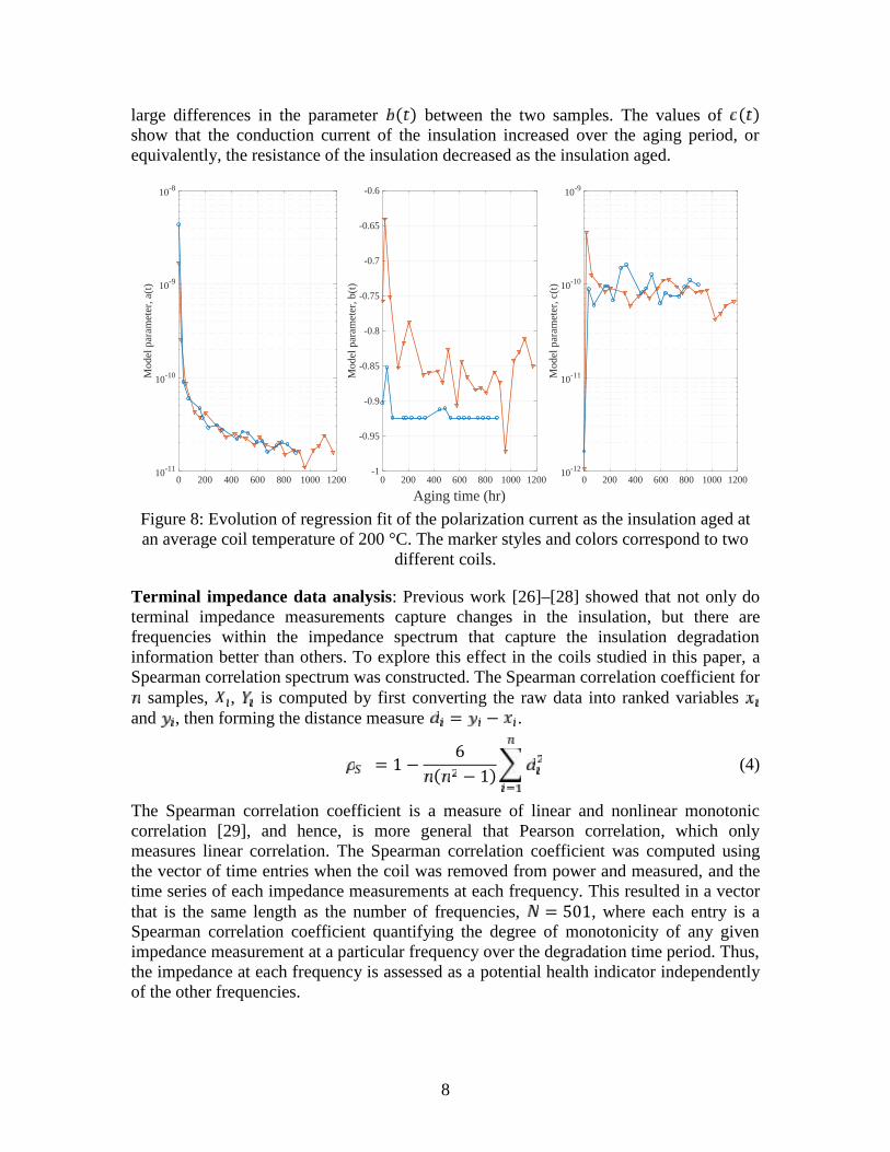
Figure 11: Change in reactance at = 778.1 kHz (left) and = 1.262MHz (right) overthe aging period for three coils. The line colors and markers correspond to three different
coils.
Table 1: Percent changes in relevant frequencies for resistance and reactance, and thechanges in the resonant frequency for all three coils.
Percent change:% change = − ⁄ × 100%Frequency Resistance, = ℜ{ } Reactance, = ℑ{ } Resonant frequency
778.1 kHz 73.65, 77.20, 85.59 * *1.262 MHz 79.93, 76.57, 66.75 * *604 kHz * 30.69, 29.43, 23.60 *853.2 kHz * 263.1, 254.3, 217.7 *
* * * 15.60, 14.89, 13.30
The data shown in Table 1 demonstrates the relative sensitivity of frequencies below andabove the coil resonant frequency to changes in the electrical properties of the insulation.Further, the trends are repeatable across three samples. Not all coils (with variousgeometries and insulation materials) experience the same amount of migration of theresonant frequency with aging. It is therefore necessary to observe the most sensitivefeature, which is shown not to be the resonant frequency, contrasting with suggestions in[10]–[12].
Conclusion: The degradation of insulation in electromagnetic coils can result in failure ofthe coil, which in turn can result in the failure of the system using the coil. Past studieshave shown insulation failure to be a significant cause of failure in electric motors andsolenoid valves.
This paper investigated the changes in the electrical behavior of polyimide insulationwhile being aged at an average coil temperature of 200 °C. Polyimide is a widely-usedinsulation with high resistance to thermal degradation (rated for 240 °C) and highmechanical strength. The study presented herein showed that as polyimide insulationaged, the coil resonant frequency increased, the capacitance dropped, and the steady-stateDC resistance of the insulation decreased. This data can be used to understand the
0 500 1000 1500Aging time (hr)
0
0.5
1
1.5
2
2.5
Res
ista
nce
()
at77
8.1
kHz
104
0 500 1000 1500Aging time (hr)
80
100
120
140
160
180
200
Res
ista
nce
()
at1.
262
MH
z

11
thermal degradation nature of polyimide and to design impedance-based healthmonitoring systems for electromagnetic coils that use polyimide insulation.
The terminal impedance data was analyzed showing that within the impedance spectrum,there are frequencies that are very sensitive to changes in the electrical properties of theinsulation. Four frequencies were given that had percent changes between 2 and 16 timeslarger than that experienced by the resonant frequency. This provides furtherexperimental support to the hypothesis presented in [26] and [27]. Moreover, a Spearmancorrelation spectrum provided a holistic view of the changes in the impedance spectra asthe coils aged, which can be related to the changes in the insulation electrical parameters.In other words, the decreasing insulation capacitance and insulation resistance resulted inthe observed changes in the impedance spectrum as the coils aged. In knowing therelationship between these variables, a suitable threshold can be established, allowing forcondition-based maintenance to be properly implemented.
Acknowledgement: The authors would like to thank Magnecomp, Inc. for generouslydonating the coils used in the presented experiments. Further thanks go to the more than100 companies that sponsor research activities at the Center for Advanced Life CycleEngineering (CALCE) at the University of Maryland annually.
References:
[1] Motor Reliability Working Group, “Report of large motor reliability survey ofindustrial and commercial installations, Part I,” IEEE Trans. Ind. Appl., vol. IA-21,no. 4, pp. 853–864, Jul. 1985.
[2] Motor Reliability Working Group, “Report of large motor reliability survey ofindustrial and commercial installations, Part II,” IEEE Trans. Ind. Appl., vol. IA-21,no. 4, pp. 865–872, Jul. 1985.
[3] O. V. Thorsen and M. Dalva, “A survey of faults on induction motors in offshore oilindustry, petrochemical industry, gas terminals, and oil refineries,” IEEE Trans. Ind.Appl., vol. 31, no. 5, pp. 1186–1196, Sep. 1995.
[4] V. P. Bacanskas, G. C. Roberts, and G. J. Toman, “Aging and service wear ofsolenoid-operated valves used in safety systems of nuclear power plants. Volume 1:Operating experience and failure identification,” Oak Ridge National Laboratory,Mar. 1987.
[5] G. C. Stone, E. A. Boulter, I. Culbert, and H. Dhirani, Electrical Insulation forRotating Machines: Design, Evaluation, Aging, Testing, and Repair. John Wiley,2004.
[6] S. Grubic, J. M. Aller, B. Lu, and T. G. Habetler, “A survey on testing andmonitoring methods for stator insulation systems of low-voltage induction machinesfocusing on turn insulation problems,” IEEE Trans. Ind. Electron., vol. 55, no. 12,pp. 4127–4136, Dec. 2008.
[7] P. J. Tavner, “Review of condition monitoring of rotating electrical machines,” IETElectr. Power Appl., vol. 2, no. 4, pp. 215–247, 2008.

12
[8] M. W. Kendig and D. N. Rogovin, “Method of conducting broadband impedanceresponse tests to predict stator winding failure,” U.S. Patent 6 323 658 B1, 27-Nov-2001.
[9] M. W. Kendig and D. N. Rogovin, “Method of conducting broadband impedanceresponse tests to predict stator winding failure,” U.S. Patent 6 483 319 B1, 19-Nov-2002.
[10] P. Werynski, D. Roger, R. Corton, and J.-F. Brudny, “Proposition of a new methodfor in-service monitoring of the aging of stator winding insulation in AC motors,”IEEE Trans. Energy Convers., vol. 21, no. 3, pp. 673–681, Sep. 2006.
[11] F. Perisse, D. Mercier, E. Lefevre, and D. Roger, “Robust diagnostics of statorinsulation based on high frequency resonances measurements,” IEEE Trans.Dielectr. Electr. Insul., vol. 16, no. 5, pp. 1496–1502, Oct. 2009.
[12] F. Perisse, P. Werynski, and D. Roger, “A new method for AC machine turninsulation diagnostic based on high frequency resonances,” IEEE Trans. Dielectr.Electr. Insul., vol. 14, no. 5, pp. 1308–1315, Oct. 2007.
[13] S. Savin, S. Ait-Amar, and D. Roger, “Organic enameled wire aging monitoringbased on impedance spectrum analysis,” in 2012 Annual Report Conference onElectrical Insulation and Dielectric Phenomena (CEIDP), 2012, pp. 874–877.
[14] K. Younsi, P. Neti, M. Shah, J. Y. Zhou, J. Krahn, K. Weeber, et al., “On-linecapacitance and dissipation factor monitoring of AC stator insulation,” IEEE Trans.Dielectr. Electr. Insul., vol. 17, no. 5, pp. 1441–1452, Oct. 2010.
[15] D.-J. Liaw, K.-L. Wang, Y.-C. Huang, K.-R. Lee, J.-Y. Lai, and C.-S. Ha,“Advanced polyimide materials: Syntheses, physical properties and applications,”Prog. Polym. Sci., vol. 37, no. 7, pp. 907–974, Jul. 2012.
[16] A. Georgiev, D. Dimov, E. Spassova, J. Assa, P. Dineff, and G. Danev, “Chemicaland Physical Properties of Polyimides: Biomedical and Engineering Applications,”in High Performance Polymers - Polyimides Based - From Chemistry toApplications, M. J. M. Abadie, Ed. InTech, 2012.
[17] “D2307 − 07a: Standard Test Method for Thermal Endurance of Film-InsulatedRound Magnet Wire.” ASTM International, 2013.
[18] L. Li, N. Bowler, P. R. Hondred, and M. R. Kessler, “Dielectric response ofpolyimide to thermal and saline degradation,” in 2010 Annual Report Conference onElectrical Insulation and Dielectric Phenomena (CEIDP), 2010, pp. 1–4.
[19] S. Diaham, M. L. Locatelli, and T. Lebey, “Improvement of Polyimide ElectricalProperties During Short-Term of Thermal Aging,” in 2008 Annual ReportConference on Electrical Insulation and Dielectric Phenomena, 2008, pp. 79–82.
[20] R. Khazaka, M. L. Locatelli, S. Diaham, and P. Bidan, “Effects of mechanicalstresses, thickness and atmosphere on aging of polyimide thin films at hightemperature,” Polym. Degrad. Stab., vol. 98, no. 1, pp. 361–367, Jan. 2013.
[21] J. Curie, “Recherches sur le pouvoir inducteur specifique et la conductibilite descorps cristallises,” Ann. Chim. Phys., vol. 17, pp. 385–434.
[22] E. R. von Schweidler, “Studien über die Anomalien im Verhalten der Dielektrika(Studies on the anomalous behaviour of dielectrics),” Ann. Phys., vol. 329, no. 14,pp. 711–770, Jan. 1907.
[23] A. K. Jonscher, Dielectric Relaxation in Solids. Chelsea Dielectrics Press Limited,1983.

13
[24] A. K. Jonscher, “Dielectric relaxation in solids,” J. Phys. Appl. Phys., vol. 32, no.14, p. R57, 1999.
[25] “IEEE Recommended Practice for Testing Insulation Resistance of ElectricMachinery,” IEEE Std 43-2013 Revis. IEEE Std 43-2000, pp. 1–37, Mar. 2014.
[26] N. Jordan Jameson, Michael H. Azarian, and Michael Pecht, “Impedance-basedcondition monitoring for insulation systems used in low-voltage electromagneticcoils,” IEEE Trans. Ind. Electron., vol. PP, no. 99, pp. 1–10, 2017.
[27] N. Jordan Jameson, Michael H. Azarian, Michael Pecht, Carlos Morillo, and KaiWang, “Health monitoring of solenoid valve electromagnetic coil insulation underthermal deterioration,” in Proceedings of MFPT 2016/ISA’s 62nd IIS, Dayton, OH,2016.
[28] N. Jordan Jameson, Michael H. Azarian, and Michael Pecht, “Impedance-basedhealth monitoring of electromagnetic coil insulation subjected to corrosivedeterioration,” in Proceedings of the Annual Conference of the Prognostics andHealth Management Society 2016, Denver, CO, 2016.
[29] J. L. Myers, A. Well, and R. F. Lorch, Research Design and Statistical Analysis.Routledge, 2010.