on accurate estimation of transverse stresses in
TRANSCRIPT

Computers & Structures Vol. 50, No. 3. pp. 351-365, 1994 Copyright @J 1994 Elsevier Scimx Ltd
Printed in Great Britain. All ri@tts mewed 004s7949/94 36.00 + 0.00
ON ACCURATE ESTIMATION OF TRANSVERSE STRESSES IN MULTILAYER LAMINATES
T. KANT? and B. S. MANNNATHA
Department of Civil Engineering, Indian Institute of Technology, Powai, Bombay-400 076, India
(Received 30 July 1992)
Abetraet-New numerical algorithms are proposed for the accurate evaluation of transverse stresses in general composite and sandwich laminates. A set of higher-order theories with Co isoparameteric finite elements and exact three-dimensional equilibrium equations are used. The integration of the equilibrium equations is carried out through exact surface fitting method, direct integration method and forward and central direct finite difference methods. Sixteen- and nine-noded quadrilateral Lagrangian elements with selective numerical integration techniques based on Gauss-Legendre product rules are used in the analysis. Validity of the present numerical techniques and the higher-order theories are demonstrated by comparing the present results with the available elasticity and other closed-form solutions for cross-ply, angle-ply and sandwich laminates. The exact surface fitting method is seen to give accurate estimate of the transverse stresses compared to other methods.
INTRODUCTION
Composite materials are currently enjoying a variety of engineering applications and their strength and weaknesses are beginning to be properly appreciated by designers, and they are being employed in a more rational manner [l]. One form of these materials, being used in current design studies for aircraft, is the unidirectional fibre reinforced plastic lamina. Conse- quently, these design studies incorporate structural elements such as plates and shells which are fabri- cated from a number of unidirectional laminae and the desired strength/stiffness properties of these el- ements are achieved by suitably orienting the laminae relative to the plate or shell principal axes.
In many instances these laminate structural el- ements will be moderately thick in relation to their span dimensions and in consequence of this a more refined analysis, one that takes into account trans- verse shear deformation, is required if the flexure response is to be adequately predicted. The classical lamination theory based on the Kirchhoff hypoth- esis [l] and the first-order shear deformation theories based on Reissner [2] and Mindlin [3] cannot be em- ployed for this analysis. This is because the classical lamination theory ignores the effect of transverse shear deformation, normal stress/strain and non- linear in-plane normal strain distribution through the laminate thickness [l] and the first-order shear defor- mation theory even though it considers the effect of transverse shear deformation, but assumes it as con- stant, thus a fictitious shear correction coefiicient is used to correct the strain energy of deformation. To overcome all these discrepancies, Reissner [4],
t To whom all correspondence should be addressed.
Lo et al. [5,6] and Kant [7] presented higher-order theories which take care of the shear deformation, transverse normal stress/strain effects. Kant et al. 181 were the first to present a Co finite element formu- lation of a higher-order theory.
Pandya and Kant [9-l l] and Kant and Manju- natha [12, 131 have extended this theory for general composite and sandwich laminates. Reddy [14], Phan and Reddy [15] and Pucha and Reddy 1161 have presented a closed-form, C’ displacement finite element and Co mixed finite element formu- lations, respectively, of a theory based on a displacement model given by Murthy [17] and Levinson [18]. But these neglect the effects of trans- verse normal stress/strain. Pandya and Kant [l l] have also given a novel approach of imposing the zero transverse shear stress conditions on top and bottom bounding planes of the laminates by modify- ing the shear rigidity matrix instead of the displace- ment model [14, 17, 191.
Further, in the evaluation of in-plane and trans- verse stresses, the constitutive relation can be used to accurately evaluate the in-plane stresses, but the same cannot be used for the evaluation of transverse stresses as it violates the continuity of these stresses at the interfaces. Thus, transverse stresses are gener- ally evaluated by using the three-dimensional equi- librium equations. Engblom and Ochoa [20,21] have modified the displacement field to specify element behaviour and to get a good estimate of in-plane and transverse stresses by using higher-order theories. But, in estimation of these stresses, the formulation obtains n equations in n - 1 unknowns, thus the equations set becomes overdetermined. These equations are solved by utilizing a least square orthononnalization procedure.
351
brought to you by COREView metadata, citation and similar papers at core.ac.uk
provided by Publications of the IAS Fellows
352 T. KANT and B.
The main aim of the present work is to accurately evaluate the transverse shear and normal stresses by using three-dimensional equilibrium equations. The integration of the equilibrium equations is attempted through direct integration method, forward and central direct finite difference methods and a new approach called exact surface fitting method. The numerical results obtained by these methods for different models are compared with the available two-dimensional finite element [14-211, elasticity [22,23] and two-dimensional closed- form [24-271 solutions.
wfx,Y,z)=%(x,Y) (2)
HOST1 1
THEORY AND FORMULATIONS
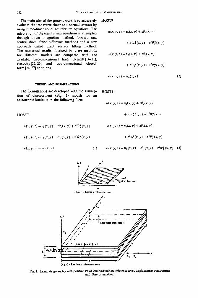
The formulations are developed with the assump- tion of dispia~m~nt (Fig. 1) models for an anisotropic laminate in the following form
HOST7
w(x,y,z)=~c(x~Y) (1)
S. MANJUNATHA
HOST9
@,Y,Z) =4&y) + &(x,y)
+zZtr,*(x,y)fz30,*(x,y)
W, Y, z) = &4x, Y) “I- zqx, y)
+z2v,*(x,y)f238_~(x,y)
4% Y, z) = w*(x, y) + ze,(x, y) -I- 22WQ(X, y) (3)
( 1,2,3) - Lamina reference axc8
Fig. 1
(x.y.2) - Laminate reference axes
. Laminate geometry with positive sat of l~ina/iaminata reference axes, displa~ment and fibre orientation.
components
Estimation of transverse stresses in multilayer laminates 353
HOST12
u(x, Y, z) = dx, Y) + zUx, Y) + Z2~~(X, Y)
+ 3ef(x, Y). (4)
In the above relations, the terms u, u and w are the displacements of a general point (x, y, z) in the laminate domain in the x, y and z directions respectively. The parameters u,,, v,, are the in-plane displacements and w, is the transverse displacement of a point (x, y) on the middle plane. The functions e,, 8, are rotations of the normal to the middle plane about y and x axes, respectively. The parameters u$,
Ud, w;, 0:) 0;) 0: and 0, are the higher-order terms in the Taylor’s series expansion and they represent higher-order transverse cross sectional deformation modes.
The full three-dimensional and its reduced forms of strain displacement and constitutive relations appropriate to the chosen displacement models are used in this formulation [g-13,31]. The theories based on the above higher-order displacement models lead to non-vanishing trans- verse shear and normal stresses on the top and bottom bounding planes of the laminate. Pandya and Kant [ll] have modified the shear rigidity matrix as against the displacement model [14, 17,191 to incorporate the zero shear conditions. Their tech- nique retains the Co continuity of displacements including the higher-order ones. This procedure is used for displacement model with seven degrees of freedom (HOST7B). But the results obtained by models which do not satisfy top and bottom zero shear condition are in general better compared to models where this condition is satisfied. This was seen to be more true in the case of thick laminates [ 1 I].
The evaluation of transverse stresses (T,, , Tag, a,)
from the stress-strain constitutive relations leads to discontinuity at the interface of two adjacent layers (laminae) of a laminate and thus violates the equilibrium conditions. The three-dimensional analysis becomes very complex due to the thickness variation of constitutive laws and continuity require- ments of transverse stresses and displacements across the interfaces. Thus, elasticity equilibrium equations are used to derive expressions for the transverse
stresses in the Lth lamina of a multilayered laminate, namely
!%+c!s+!+ aY
!.!A+%++). ay
(5)
The integration of these equilibrium equations is attempted here through different novel approaches: direct integration method, forward and central direct finite difference methods and a new approach called an exact surface fitting method. These methods are explained below.
(a) Direct integration method
The three differential equations of equilibrium given by eqns (5x7) give three relations, namely,
~=_(~+f!$Y) (8)
and
ab ah 2=2+
a+7 --2+2!.& a22 ax2 ay2 (10)
from which the transverse stresses 7_, T,,~ and a, can be evaluated through integration with respect to the laminate thickness z. The in-plane stresses CT~ and uY and the in-plane shear stress TV,, obtained by constitu- tive relations are substituted in eqns @-(IO). It can be seen that eqns (8) and (9) are first-order equations in 7xr and 7yz. Solving these equations one obtains only one constant of integration, this being an initial value problem. However, this problem is vexing because the value of transverse shear stresses are normally known at both top and bottom boundary surfaces of the laminate. Thus one obtains only a non-unique solution for transverse shear stresses as two prescribed condition for these stresses cannot be simultaneously enforced in the solution. In the case of transverse normal stress [eqn (lo)] a second-order equation is obtained. By integrating the second-order differential equation twice, two constants of inte- gration are obtained. These constants of integration can be determined by substituting the two boundary conditions on the top and bottom surfaces of the laminate.
354 T. KANT and B. S. MANJUNATHA
AA = ax(GP + 4) - a,(GJ’)
AX I
The final form of the computational algorithms for 7rr, 7!._ and eZ after integration through the laminate thickness can be written as follows:
.,,,,,=-~,~~+‘(~+~)dz+C, (11)
+2 a22, ax ay > >
dz dz + zC, + C,. (13)
The constants C, and C, are obtained from the known values of 7xr and tyz at either of the two boundaries at z = &h/2 while constants C, and C, are obtained from the known values of Q, at z = f h/2. However, eqn (13) requires the use of third derivatives of displacements. For this reason cubic sixteen-noded quadrilateral Lagrangian elements in addition to nine-noded elements are used here. The presence of second and third derivatives of displace- ments in the stress evaluation dictates the use of high degree polynomial elements and further introduction of numerical error in the estimation of transverse shear and normal stresses. Thus, forward and central direct finite difference (FDM) methods and a new approach called exact surface fitting method (ESFM) are proposed to accurately estimate the transverse shear and normal stresses. Here a formulation for sixteen-noded element is presented. The same pro- cedure is also used for nine-noded element.
(b) Finite difference methods
Here also in-plane stresses are evaluated by using constitutive relations at different Gauss points in an element (4 x 4 sixteen points for sixteen-noded and 3 x 3 nine points for nine-noded). After that, the forward difference method (stresses are maximum at the edges of the laminate) is used in the x-y plane to evaluate the derivatives of in-plane stresses at a particular Gauss point inside the element and either a forward difference or a backward difference method is used for the evaluation of the same at the edges of the laminate depending on whether the edge is a positive or negative one. The following equations corresponding to eqns (8) and (9) are obtained
S=_*B az
(14)
(15)
+ 7,W + 1) - 7,JGP)
AY 1 (16) BB = qv(Gf’ + 1) - QGJ’)
AY 1 +
7,,(Gf’ + 4) - r,(GP)
AX ]> (17)
where GP is the Gauss point number at which stresses are evaluated and GP + 4 and GP + 1 are the next Gauss point numbers in the .Y and y directions respectively, where the stresses are evaluated.
Forward difference method. The final form of the computational algorithms for t,: and 7!; after using the forward difference operator along the thickness direction in eqns (14) and (15) are written as follows (these are designated as the forward-direct difference method)
71;llL+,=71;21-_L-[AAlL*(-1L+,-=L) (18)
7titrr+, =7,LZI;,-[[BB]L*(=L+,-~L). (19)
Central difference method. The following compu- tational algorithms are obtained for r,: and rvI after using the central difference operator along the thick- ness direction in eqns (14) and (15) (these are desig- nated as central-direct difference method) [30]
in which
@L-t, -2L) a =(z,-zL_,). (22)
As the central difference method is a two-step non-self-starting method, the forward difference method is used to evaluate the transverse stresses at first step and for subsequent steps central difference method is used. This method can be effectively used for isotopic laminates. For laminates having different isotropic, orthotropic or anisotropic laminae, the in-plane stresses are discontinuous and two values are obtained at an interface of two layers. As the trans- verse stresses are continuous through the interface of two layers, the derivatives of in-plane stresses must also be continuous through the interface. Thus, an average of the two values at the interface is used in the above techniques.
Estimation of transverse stresses in multilayer laminates 355
(c) Exact surface fitting method
Here also in-plane stresses are evaluated through constitutive relations at different Gauss points in an element. After obtaining the in-plane stresses acting on lower and upper surfaces of a particular layer, the variation of these stresses over a particular surface of an element can be expressed as a polynomial in laminate axes (x, y) as follows:
a,(z) = Cf + c&X + c;y + c; x* + c;xy + c:y*
+c;x3+c;xzy+c;xy*+c;,y3
+ c;,x3y + c;,xzy* + c;,xy3 + c;,x3y*
+ c;,x*y3 + Cf,x3y3. (23)
Similar equations are obtained for av and rXy. The parameter in eqn (23), z refers to a particular surface in the laminate at a distance z from the middle plane and this may be the top or bottom surface of a particular lamina or a subset of a particular lamina having same ply orientations. The following equation is obtained by substituting the in-plane stresses at is obtained by subsltituting the in-plane stresses at different Gauss points in an element
[ A, I[ CJ I = [,,fE;,l, (24) (16 x 16) (16 x I)
Similar equations are obtained for u,, and T.+,. The above equation is solved and the sixteen polynomial constants are obtained. Equation (23) is differentiated with respect to x and y and thus derivatives of in-plane stresses are obtained. These are written as follows:
au 2 = c; + 2c;x + c;y + 3c;x* + 2c;xy + c;y* ax
+ 3c;,x*y + 2Cf,xy2 + c;,y3 + 3c;,xry*
+ 2c;,xy3 + 3c;,x*y3 (25)
a% I = 2C; + 6C;x + 2C;y + 6C;,xy + 2C;,y* ax*
+ 6C;4xy2 + 2C;,y3 + 6C;,xy3. (26)
Similar equations are obtained for o,, and rXy. These derivatives are then used in eqns (8) and (9) and the same procedure as used for the direct finite difference method is used following eqns (18)-(22).
The final form of the computational algorithm for a, after using the central difference operator along the thickness direction in eqn (10) is written as follows:
2. (27)
The double derivatives of in-plane stresses are substituted in eqn (27) and this equation is solved as a boundary value problem by substituting the two boundary conditions for transverse normal stresses at top and bottom surfaces of the laminate.
The displacement models given by eqns (l)-(4) are used in conjunction with Co isoparameteric finite elements in the x-y plane and the same has been explained in detail in [12]. Lagrangian quadrilateral elements with 9 and 16 nodes are used. A selective numerical integration technique based on Gauss-Legendre product rules is used here for the evaluation of the element stiffness properties.
NUMERICAL RESULTS AND DISCUSSION
To demonstrate the accuracy and efficiency of the present higher-order theories and the new numerical techniques, a set of computer program incorporating the higher-order theories are developed for the elasto- statics of general composite and sandwich laminates. All the computations are carried out on a CYBER 180/840 computer in single precision with sixteen significant digits word-length. A computer program based on the Reissner/Mindlin theory has also been developed to support the numerical evaluations of the present formulations. The transverse shear energy terms in the Reissner/Mindlin theory are corrected by using a shear correction coefficient of 5/6 for all the materials used here. Selective numerical integration technique, based on Gauss-Legendre product rules, namely 4 x 4 for flexure/membrane and 3 x 3 for shear terms has been employed for sixteen-noded elements and 3 x 3 for flexure/membrane and 2 x 2 for shear terms, has been employed for nine-noded elements in the analysis. Due to biaxial symmetry, only one quadrant of the laminate is considered in the case of crossply laminates and for angle-ply and general sandwich laminates full laminate is con- sidered in the analysis.
The values of in-plane, transverse stresses are evaluated at the Gauss points, whereas the displace- ments are computed at the nodal points. A 2 x 2 mesh (four elements) for cross-ply laminates (quarter laminate) and a 4 x 4 mesh (sixteen elements) for angle-ply and general sandwich laminates (full lami- nate) were seen to give generally converged displace- ments and stresses for nine-noded elements. Similarly, one element for cross-ply laminates and 2 x 2 mesh (four elements) for angle-ply and general
356 T. KANT and B. S. MANJLJNA~HA
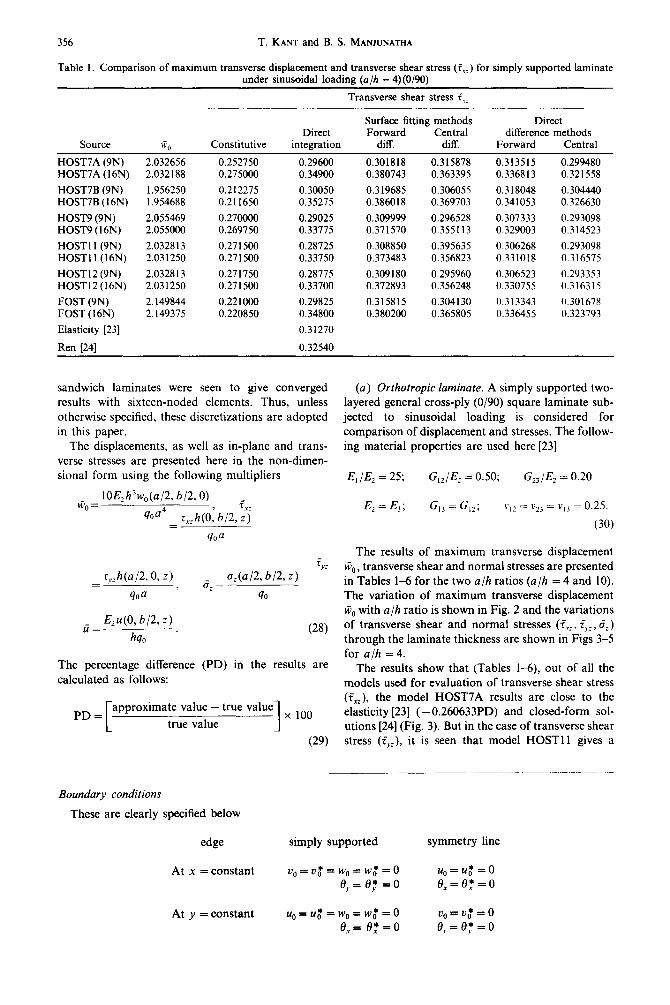
Table 1. Comparison of maximum transverse displacement and transverse shear stress (i,,) for simply supported laminate under sinusoidal loading (u/h = 4) (O/90)
Transverse shear stress f,, __~~___
Surface fitting methods Direct Direct Forward Central difference methods
Source Go Constitutive integration diff. diff. Forward Central
HOST7A (9N) HOST7A (16N)
HOST7B (9N) HOST7B (16N)
HOST9 (9N) HOST9 (16N)
HOST1 l(9N) HOST11 (16N)
HOST12 (9N) HOST12 (16N)
FOST (9N) FOST(l6N)
Elasticity [23]
Ren 1241
2.032656 2.032188
1.956250 1.954688
2.055469 2.055000
2.032813 2.031250
2.032813 2.031250
2.149844 2.149375
0.252750 0.275000
0.212275 0.211650
0.270000 0.269750
0.271500 0.27 1500
0.271750 0.271500
0.221000 0.220850
0.29600 0.34900
0.30050 0.35275
0.29025 0.33775
0.28725 0.33750
0.28775 0.33700
0.29825 0.34800
0.31270
0.32540
0.301818 0.315878 0.313515 0.299480 0.380743 0.363395 0.336813 0.321558
0.3 19685 0.306055 0.318048 0.304440 0.386018 0.369703 0.341053 0.326630
0.309999 0.296528 0.307333 0.293098 0.371570 0.355113 0.329003 0.314523
0.308850 0.395635 0.306268 0.293098 0.373483 0.356823 0.331018 0.316575
0.309180 0.295960 0.306523 0.293353 0.372893 0.356248 0.330755 0.316315
0.315815 0.304130 0.313343 0.301678 0.380200 0.365805 0.336455 0.323793
sandwich laminates were seen to give converged (a) Orthotropic laminate. A simply supported two- results with sixteen-noded elements. Thus, unless layered general cross-ply (O/90) square laminate sub- otherwise specified, these discretizations are adopted jetted to sinusoidal loading is considered for in this paper. comparison of displacement and stresses. The follow-
The displacements, as well as in-plane and trans- ing material properties are used here [23] verse stresses are presented here in the non-dimen- sional form using the following multipliers E, /El = 25; G,JEz = 0.50; G2JE2 = 0.20
biJCj= 10Ezh3w,(a/2, b/2,0) _
qoa4 rxzh(O: b,2,$ =
qoa
Ez=E,; G,, = G,,; ~3,~ = vz3 = vi3 = 0.25.
130)
The results of maximum transverse displacement F?:
= r,,h(a/2,0, r) 6; =
a&/2, b/2,2) GO, transverse shear and normal stresses are presented
qOa ’ in Tables l-6 for the two a/h ratios (a/h = 4 and IO).
40 The variation of maximum transverse displacement
E,@, b/2, z) Go with a/h ratio is shown in Fig. 2 and the variations
G= hq, .
(28) of transverse shear and normal stresses (f,,, TVl, 6:) through the laminate thickness are shown in Figs 3-5
The percentage difference (PD) in the results are for a/h = 4.
The results show that (Tables l-6), out of all the calculated as follows: models used for evaluation of transverse shear stress
value - true value (fXZ), the model HOST7A results are close to the
PD= approximate 1 x 100 elasticity [23] (- 0.260633PD) and closed-form sol-
true value utions [24] (Fig. 3). But in the case of transverse shear
(29) stress (Q,:), it is seen that model HOST11 gives a
Boundary conditions
These are clearly specified below
edge simply supported symmetry line
At x = constant
At y = constant
vo=Vg*=wo=w~=o e,. = e,t = 0
u~=r4o+=w~=wg*=o e,= e:=o
u,=u,*=o e,=e: =o
00 = v$ = 0 e,. = e_; = 0
Estimation of transverse stresses in multilayer laminates 357
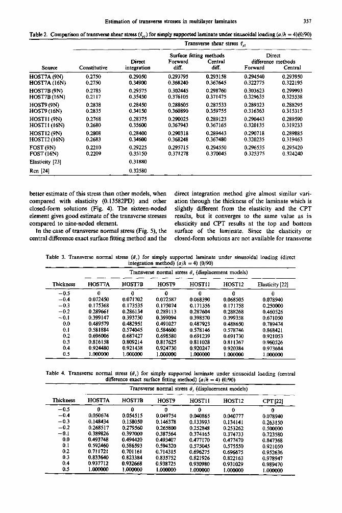
Table 2. Comparison of transverse shear stress &) for simply supported laminate under sinusoidal loading (a/h = 4)(0/W)
Transverse shear stress fYz
source Constitutive Direct
integration
Surface fitting methods Direct Forward Central difference methods
diff. diff. Forward Central
HOST’IA (9N) 0.2750 0.29050 0.293795 0.293158 0.294540 0.293950 HOST’IA ( 16N) 0.2750 0.34900 0.368240 0.367645 0.322775 0.322195
HOST7B (9N) 0.2785 0.29575 0.302445 0.298760 0.303623 0.299993 HOST’IB (16N) 0.2117 0.35450 0.376105 0.371475 0.329635 0.325538
HOST9 (9N) 0.2838 0.28450 0.288605 0.287533 0.289323 0.288295 HOST9(16N) 0.2835 0.34150 0.360890 0.359755 0.316363 0.315315
HOST1 l(9N) 0.2768 0.28375 0.290025 0.289123 0.290443 0.289590 HOST1 l(l6N) 0.2680 0.35600 0.367943 0.367165 0.320135 0.319233
HOST12 (9N) 0.2808 0.28400 0.290318 0.289443 0.290718 0.289885 HOST12 (16N) 0.2683 0.34600 0.368248 0.367480 0.320235 0.319463
FOST (9N) 0.2210 0.29225 0.295715 0.294550 0.296535 0.295420 FOST (16N) 0.2209 0.35150 0.371278 0.370045 0.325375 0.324240
Elasticity [23] 0.31880
Ren [24] 0.32580
better estimate of this stress than other models, when direct integration method give almost similar vari- compared with elasticity (0.13582PD) and other ation through the thickness of the laminate which is closed-form solutions (Fig. 4). The sixteen-noded slightly different from the elasticity and the CPT element gives good estimate of the transverse stresses results, but it converges to the same value as in compared to nine-noded element. elasticity and CPT results at the top and bottom
In the case of transverse normal stress (Fig. 5), the surface of the laminate. Since the elasticity or central difference exact surface fitting method and the closed-form solutions are not available for transverse
Table 3. Transverse normal stress (Zz) for simply supported laminate under sinusoidal loading (direct integration method) (u/h = 4) (O/90)
Transverse normal stress ez (displacement models)
Thickness HOST’IA HOST’IB HOST9 HOST1 1 HOST12 Elasticity [22]
-0.5 0 0 0 0 0 0 -0.4 0.072450 0.071702 0.072587 0.068390 0.068505 0.078940 -0.3 0.175368 0.173535 0.175074 0.171356 0.171758 0.250000 -0.2 0.289661 0.286134 0.289113 0.287604 0.288268 0.460526 -0.1 0.399147 0.393730 0.399094 0.398570 0.399358 0.671050
0.0 0.489579 0.482951 0.491027 0.487923 0.488650 0.789474 0.1 0.581884 0.574045 0.584600 0.578146 0.578746 0.86842 I 0.2 0.696006 0.687427 0.698580 0.691239 0.691730 0.921053 0.3 0.816158 0.809214 0.817625 0.811028 0.811367 0.960526 0.4 0.924480 0.921438 0.924730 0.920247 0.920384 0.973684 0.5 l.OOOOOO l.OoOOOO MtOOOOo l.OOOOOO l.OOoOOO l.oooooo
Table 4. Transverse normal stress (5,) for simply supported laminate under sinusoidal loading (central difference exact surface fitting method) (u/h = 4) (O/90)
Transverse normal stress 8: (displacement models)
Thickness HOST7A HOST’IB HOST9 HOST1 1 HOST12 CPT [22]
-0.5 0 0 0 0 0 -0.4 0.050674 0.054515 0.049754 0.040865 0.040777 -0.3 0.148434 0.158050 0.146378 0.133993 0.134141 -0.2 0.268517 0.279560 0.265800 0.252848 0.253262 -0.1 0.389826 0.397000 0.387564 0.374165 0.374733
0.0 0.493748 0.494420 0.493407 0.477170 0.477470 0.1 0.592460 0.586593 0.594320 0.575045 0.575550 0.2 0.711721 0.701161 0.714315 0.696275 0.696675 0.3 0.833640 0.823384 0.835752 0.821926 0.822163 0.4 0.937712 0.932668 0.938725 0.930980 0.931029 0.5 l.OOOOOO l.OOOOOO 1.OOOOOO l.OOOOOO l.OOOOOO
0 0.078940 0.263150 0.500&O 0.723580 0.847368 0.921050 0.952636 0.978947 0.989470 l.OOOOOO

358 T. KANT and B. S. MANJUNATHA
Table 5. Comparison of maximum transverse displacement and transverse shear stress (f.rz) for simply supported laminate under sinusoidal loading (a/h = 10) (O/90)
Transverse shear stress i.XL
Surface fitting methods Direct difference Direct Forward Central methods
Source WO Constitutive integration diff. diff. Forward Central
HOST’IA (9N) 1.2203 0.2564 0.2980 0.315881 0.303760 0.313420 0.301321 HOST’IA ( 16N) 1.2201 0.2565 0.3476 0.380247 0.365304 0.336454 0.323314
HOSTIIB (9N) 1.2128 0.2780 0.2975 0.315874 0.303209 0.313437 0.300749 HOST’IB ( 16N) 1.2124 0.2782 0.3476 0.380389 0.365335 0.336571 0.323273
HOST9 (9N) 1.2237 0.2728 0.2972 0.315226 0.303227 0.312724 0.300749 HOST9 ( 16N) 1.2236 0.2729 0.3463 0.378674 0.363899 0.335126 0.322131
HOST1 l(9N) 1.2200 0.2735 0.2974 0.315731 0.303784 0.313193 0.301270 HOST1 l(l6N) 1.2200 0.2736 0.3467 0.379306 0.364467 0.336032 0.323012
HOST12 (9N) 1.2200 0.2735 0.2974 0.3 15743 0.303795 0.313200 0.301277 HOST12 (16N) 1.2200 0.2736 0.3467 0.379293 0.364455 0.336026 0.323006
FOST (9N) 1.2378 0.2209 0.2983 0.315853 0.304167 0.313375 0.301710 FOST (16N) 1.2377 0.2208 0.3480 0.380177 0.36578 1 0.336416 0.323752
Elasticity [23] 0.3310
Ren [24] 0.3320
displacement Ws, this has been compared with Mindlin theory for model HOST9 (Fig. 2).
(b) Angle-ply laminate. A two-layered simply sup- ported general angle-ply (1 So/ - 15”) square laminate subjected to sinusoidal loading is considered. The following material properties are used [25]
E, /El = 40; G,2/E2 = 0.50: G,,/E, = 0.60,
E,=E,; G,, = G,z; VIZ = v2, = v,j - - 0.25.
(31)
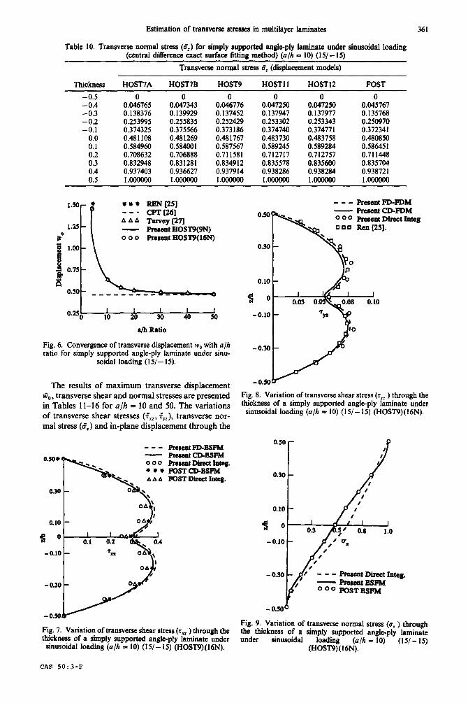
The results of maximum transverse displacement Go, transverse shear and normal stresses for a/h = 10 are presented in Tables 7-10. The variation of the maximum transverse displacement G,, with a/h ratio is shown in Fig. 6 and the variations of transverse
shear and normal stresses through the laminate thick- ness are shown in Figs 7-9 for a/h = 10.
The results show that the transverse displacement G,, obtained by model HOST9(9N) is close to closed- form solution [25] (- 1.5148PD) compared to other models. The classical plate theory underestimates the value and gives a poor estimate for thick laminates (Fig. 6) (-28.0111PD). As the laminate thickness is reduced (a/h = 50 and above) all the theories almost give same results, thus showing the validity of the present higher-order theory.
The transverse shear stress (fVI) results show that the model HOST9 gives a good estimate of the stress (-0.02158PD) compared to other models. Out of the two elements used, it is seen that sixteen-noded elements give a better estimate of these stresses compared to the other element.
Table 6. Comparison of transverse shear stress (fYz) for simply supported laminate under sinusoidal loading (a/h = 10) (O/90)
Source
HOSTIIA (9N) HOST’IA (16N)
HOST7B (9N) HOSTIIB (16N)
HOST9 (9N) HOST9 (16N)
HOST ll(9N) HOST11 (16N)
HOST12 (9N) HOST12 (16N)
FOST (9N) FOST (16N)
Constitutive
0.2811 0.2811
0.3178 0.3179
0.2880 0.2881
0.2816 0.2869
0.2868 0.2869
0.2209 0.2208
Transverse shear stress $,._
Direct integration
0.2922 0.3513
0.2917 0.3513
0.2914 0.3501
0.2898 0.3509
0.2898 0.3509
0.2924 0.3517
Surface fitting methods Direct difference Forward Central methods
diff. diff. Forward Central
0.295680 0.294610 0.296484 0.295463 0.371078 0.369960 0.325146 0.324110
0.294803 0.293813 0.295586 0.294645 0.371053 0.369942 0.325034 0.324020
0.295259 0.294108 0.296050 0.294946 0.369912 0.368695 0.324131 0.32301 I
0.293897 0.292744 0.294885 0.293779 0.369420 0.368222 0.306180 0.300894
0.293920 0.292768 0.294898 0.293793 0.369435 0.368238 0.323298 0.322191
0.295917 0.294750 0.296736 0.295618 0.371634 0.370399 0.325621 0.324483

Estimation of transverse stresses in multilayer laminates
0.50 * - xcat9(9N)
0 0 0 Hcat9(16N) * l * Fort(9N) ---cPT
i
0.30
0.10
0.7So I I I I I
10 20 30 40 50
Fig. 2. Convergence of transverse displacement w,, with a/h ratio for simply supported laminate under sinusoidal load-
ing (O/90).
Thus, in Fig. 8, the variation of transverse shear stress obtained by different methods has been shown for the model HOST9. From this figure, it can be seen that direct finite difference method gives good estimate of transverse shear stresses compared to other methods. As the closed-form solutions for transverse shear (CXZ) and normal stresses are not available, these results are compared with the Reissner/Mindlin theory for model HOST9. These results show that central difference exact surface fitting method gives a much better estimate of the transverse normal stress compared to direct inte- gration method.
(c) Sandwich laminate. A clamped general eight- layered sandwich laminate (O”/4So/ - 45”/3O”/core/ O”/900/Oo) under uniformly distributed loading is considered. The following material properties are used [28,29]
cl 0 0 Elasticity [23] AAA bn[24] ---PraemtFD-Bsm - 0.30 PreaentFD-FDM 0 0 0 Pmaent direct rnteg.
-0.10 -
-0.30 -
Fig. 3. Variation of transverse shear stress (T, ) through the thickness of a simply supported laminate under sinusoidal
359
o o o Blasticity 1231 AAA h-Il[24]
- 0.30 ---PfwentFD-FDM - x%eBentcD-FDM 0 00 Prcaent Direct Integ.
- 0.50~ Fig. 4. Variation of transverse shear stress (rYz ) through the thickness of a simply supported laminate under sinusoidal
loading (u/h = 4) (O/W) (HOST1 1)(16N).
stiff layers
E, = 0.1308 x 10⁸ psi; E,=E,=O.l06x 1O’psi
G,r = G,, = 0.6 x lo6 psi; G,, = 0.39 x lo6 psr
VI2 = VI3 - - 0.28; v23 = 0.34
core layers
G,, = 0.1772 x lo5 psi; G,, = 0.5206 x IO5 psi
h,/h, = 8 [other properties are zero]. (32)
- 0.30 0 0 0 Slaaticity [22] AAA Cm[22] - - - Resent Direct Meg. - PrcsentBSFM
-o.mA
loading (u/h = 4) (O/W) (HOST7A)(9N).
Fig. 5. Variation of transverse normal stress (u, ) through the thickness of a simply supported laminate under sinu- ._ . . .
soidal loading (a/h = 4) (O/W) (HOST9)(16N).
360 T. KANT and B. S. MANJUNAT-HA
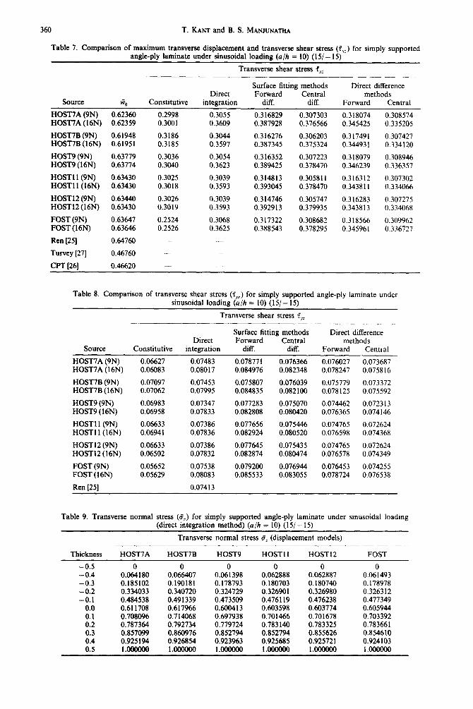
Table 7. Comparison of maximum transverse displacement and transverse shear stress (f,,) for simply supported angle-ply laminate under sinusoidal loading (u/h = 10) (15/ - 15)
Transverse shear stress f.X,,
Source Constitutive Direct
integration
Surface fitting methods Direct difference Forward Central methods
diff. diff. Forward Central
HOST7A (QN) 0.62360 HOST7A (16N) 0.62359
HOST’IB (QN) 0.61948 HOST’IB (16N) 0.61951
HOST9 (QN) 0.63779 HOSTQ(16N) 0.63774
HOST1 1 (QN) 0.63430 HOST1 l(l6N) 0.63430
HOST12 (QN) 0.63440 HOST12 (16N) 0.63430
FOST (QN) 0.63647 FOST (16N) 0.63646
Ren [25] 0.64760
Turvey [27] 0.46760
CRT f261 0.46620
0.2998 0.3055 0.316829 0.307303 0.318074 0.308574 0.3001 0.3609 0.387928 0.376566 0.345425 0.335205
0.3186 0.3044 0.316276 0.306203 0.317491 0.307427 0.3185 0.3597 0.387345 0.375324 0.34493 I 0.334120
0.3036 0.3054 0.316352 0.307223 0.318079 0.308946 0.3040 0.3623 0.389425 0.378470 0.346239 0.336357
0.3025 0.3039 0.314813 0.305811 0.316312 0.307302 0.3018 0.3593 0.393045 0.378470 0.343811 0.334066
0.3026 0.3039 0.3 14746 0.305747 0.316283 0.307275 0.3019 0.3593 0.392913 0.379935 0.343813 0.334068
0.2524 0.3068 0.317322 0.308682 0.318566 0.309962 0.2526 0.3625 0.388543 0.378295 0.345961 0.336727
-
-
Table 8. Comparison of transverse shear stress (iYz) for simply supported angle-ply laminate under sinusoidal loading (a/h = IO) (15/- 15)
Transverse shear stress f,,._
Source Constitutive Direct
integration
Surface fitting methods Forward Central
diff. diff.
Direct difference methods
Forward Central
HOST’IA (QN) 0.06627 0.07483 0.078771 0.076366 0.076027 0.073687 HOST7A ( 16N) 0.06083 0.08017 0.084976 0.082348 0.078247 0.075816
HOST’IB (9N) 0.07097 0.07453 0.075807 0.076039 0.075779 0.073372 HOST’IB (16N) 0.07062 0.07995 0.084835 0.082100 0.078125 0.075592
HOST9 (9N) 0.06983 0.07347 0.077283 0.075070 0.074462 0.0723 I3 HOST9 (16N) 0.06958 0.07833 0.082808 0.080420 0.076365 0.074146
HOST1 l(9N) 0.06633 0.07386 0.077656 0.075446 0.074765 0.072624 HOST1 l(16N) 0.06941 0.07836 0.082924 0.080520 0.076598 0.074368
HOST12 (9N) 0.06633 0.07386 0.077645 0.075435 0.074765 0.072624 HOST12 (16N) 0.06502 0.07832 0.082874 0.080474 0.076578 0.074349
FOST (9N) 0.05652 0.07538 0.079200 0.076944 0.076453 0.074255 FOST(16N) 0.05629 0.08083 0.085533 0.083055 0.078724 0.076538
Ren [25] 0.07413
Table 9. Transverse normal stress (6;) for simply supported angle-ply laminate under sinusoidal loading (direct integration method) (a/h = 10) (IS/- 15)
Transverse normal stress d, (displacement models)
Thickness HOST’IA HOST’IB HOST9 HOST1 1 HOST12 FOST
-0.5 0 0 0 0 0 0
-0.4 0.064180 0.066407 0.061398 0.062888 0.062887 0.061493 -0.3 0.185102 0.190181 0.178793 0.180703 0.180740 0.178978 -0.2 0.334033 0.340720 0.324729 0.326901 0.326980 0.326312 -0.1 0.484538 0.491339 0.473509 0.476119 0.476238 0.477349
0.0 0.611708 0.617966 0.600413 0.603598 0.603774 0.605944 0.1 0.708096 0.714068 0.697938 0.701466 0.701678 0.703392 0.2 0.787364 0.792734 0.779724 0.783140 0.783325 0.783661 0.3 0.857099 0.860976 0.852794 0.852794 0.855626 0.854610 0.4 0.925194 0.926854 0.923963 0.925685 0.925721 0.924103 0.5 l.OOOOOO l.OOOOOO 1.OOOOOO 1.OOOOOo 1.OOOOOO 1.OOOOOO
Estimation of transverse stresses in multilayer laminates 361
Table 10. Transverse normal stress (8z) for simply supported angle-ply laminate under sinusoidal loading (central difference exact surface fitting method) (o/h = 10) (lS/- 15)
Transverse normal stress Cz (displacement models)
Thickness HOST7A HOST’IB HOST9 HOST1 1 HOST12 FOST
-0.5 0 0 0 0 -0.4 0.046765 0.047343 0.046776 0.047250 -0.3 0.138376 0.139929 0.137452 0.137947 -0.2 0.253995 0.255835 0.252429 0.253302 -0.1 0.374325 0.375566 0.373186 0.374740
0.0 0.481108 0.481269 0.481767 0.483730 0.1 0.584960 0.584001 0.587567 0.589245 0.2 0.708632 0.706888 0.711581 0.712717 0.3 0.832948 0.831281 0.834912 0.835578 0.4 0.937403 0.936627 0.937914 0.938286
0.0407250 0.137977 0.253343 0.374771 0.483758 0.589284 0.712757 0.835600 0.938284
0 0.045767 0.135768 0.250970 0.372341 0.480850 0.586451 0.711448 0.835704 0.938721
0.5 1.oooooO 1.oooOoo 1.oooooO 1.OOOOOO l.OOOOOO 1.OOOOOO
** * REN [25} - - - CPT [261 AAA Tnrviy[271 - ReEent HOSlY(9N) o o o present HOST9(16N)
OeZOZ 50
a/h Ratio
Fig. 6. Convergence of transverse displacement w0 with U//I ratio for simply supported angle-ply laminate under sinu-
soidal loading (15/- 15).
The results of maximum transverse displacement @,,, transverse shear and normal stresses are presented in Tables 11-16 for a/h = 10 and 50. The variations of transverse shear stresses (fXz. f,,), transverse nor- mal stress (8,) and in-plane displacement through the
- - - Prerent PD-BSFM - ResentcD-ESFM 000 PitwelltDlrectlnteg. l ** FOSTCD-BgFM A A A POST Direct Inbeg.
0.30 -
0.10 -
Fig. 7. Variation of transverse shear strew (7, ) through the thickness of a simply supported angle-ply laminate under
sinusoidal loading (a/h = 10) (15/- 15) (HOST9)(16N).
-em Resent FD-FDM - Present CD-FDM Ooo PresentDirectInteg 000 Ren[25].
A 0.10
Fig. 8. Variation of transverse shear stress (7 ,: ) through the thickness of a simply supported angle-ply laminate under
sinusoidal loading @//I = 10) (15/- 15) (HOST9) (I 6N).
---ResentDirectInteg. - PmaentEsFM Ooo FOSTBSFM
Fig. 9. Variation of transverse normal stress (u, ) through the thickness of a simply supported angle-ply laminate under sinusoidal loading (o/h = 10) (IS/- 15)
(HOST9)(16N).
CAS 50:3-E
362 T. KANT and B. S. MANJUNATHA
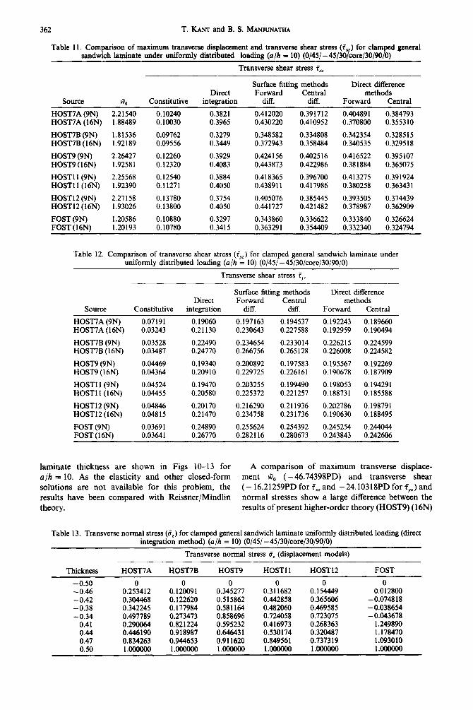
Table 11. Comparison of maximum transverse displacement and transverse shear stress (6) for clamped general sandwich laminate under uniformly distributed loading (a/h = 10) (O/45/ -45/3O/core/30/90/0)
Transverse shear stress fXz
Source
HOST7A (9N) HOST7A (16N)
HOST7B (9N) HOST’IB (16N)
HOST9 (9N) HOST9 (16N)
HOST ll(9N) HOST1 l(l6N)
HOST 12 (9N) HOST12 (16N)
FOST (9N) FOST (16N)
*o 2.21540 1.88489
1.81536 1.92189
2.26427 1.92581
2.25568 1.92390
2.27158 1.93026
1.20586 1.20193
Constitutive
0.10240 0.10030
0.09762 0.09556
0.12260 0.12320
0.12549 0.11271
0.13780 0.13800
0.10880 0.10780
Direct integration
0.3821 0.3965
0.3279 0.3449
0.3929 0.4083
0.3884 0.4050
0.3754 0.4050
0.3297 0.3415
Surface fitting methods Direct difference Forward Central methods
diff. diff. Forward Central
0.412020 0.391712 0.404891 0.384793 0.430220 0.410952 0.370800 0.355310
0.348582 0.334808 0.342354 0.328515 0.372943 0.358484 0.340535 0.329518
0.424156 0.402516 0.416522 0.395107 0.443873 0.422986 0.381884 0.365075
0.418365 0.396700 0.413275 0.391924 0.438911 0.417986 0.380258 0.36343 1
0.495076 0.385445 0.393505 0.374439 0.441727 0.421482 0.378987 0.362909
0.343860 0.336622 0.333840 0.326624 0.363291 0.354409 0.332348 0.324794
Table 12. Comparison of transverse shear stress (fYz) for clamped general sandwich laminate under uniformly distributed loading (a/h = 10) (O/45/ -45/30/tore/30/90/0)
Transverse shear stress F,,
Surface fitting methods Direct difference Direct Forward Central methods
Source Constitutive integration diff. diff. Forward Central
HOST’IA (9N) 0.07191 0.19060 0.197163 0.194537 0.192243 0.189669 HOST’IA (16N) 0.03243 0.21130 0.230643 0.227588 0.192959 0.190494
HOST7B (9N) 0.03528 0.22490 0.234654 0.233014 0.226215 0.224599 HOST7B (16N) 0.03487 0.24770 0.266756 0.265128 0.226008 0.224582
HOST9 (9N) 0.04469 0.19340 0.200892 0.197583 0.195567 0.192269 HOST9 (16N) 0.94364 0.20910 0.229725 0.226161 0.190678 0.187909
HOST1 l(9N) 0.04524 0.19470 0.203255 0.199490 0.198053 0.194291 HOST1 l(l6N) 0.04455 0.20580 0.225372 0.221257 0.188731 0.185588
HOST12 (9N) 0.04846 0.20170 0.216298 0.211936 0.202786 0.198791 HOST12 (16N) 0.04815 0.21470 0.234758 0.231736 0.190630 0.188495
FOST (9N) 0.03691 0.24890 0.255624 0.254392 0.245254 0.244044 FOST(l6N) 0.03641 0.26770 0.282116 0.280673 0.243843 0.242606
laminate thickness are shown in Figs IO-13 for A comparison of maximum transverse displace-
a/h = 10. As the elasticity and other closed-form ment G,, ( - 46.74398PD) and transverse shear solutions are not available for this problem, the (- 16.21259PD for fX,, and -24.10318PD for f,,=) and results have been compared with Reissner/Mindlin normal stresses show a large difference between the theory. results of present higher-order theory (HOST9) (16N)
Table 13. Transverse normal stress (a,) for clamped general sandwich laminate uniformly distributed loading (direct integration method) (a/h = 10) (O/45/-45/30/tore/30/90/0)
Transverse normal stress 8, (displacement models)
Thickness HOST’IA HOST’IB HOST9 HOST1 1 HOST12 FOST
-0.50 0 0 0 0 0 0 -0.46 0.253412 0.120091 0.345277 0.311682 0.154449 0.012800 -0.42 0.304468 0.122620 0.515862 0.442858 0.365606 -0.074818 -0.38 0.342245 0.177984 0.581164 0.482060 0.469585 -0.038654 -0.34 0.497789 0.273473 0.858696 0.724058 0.723075 - 0.043678
0.41 0.290064 0.821224 0.595232 0.416973 0.268363 1.249890 0.44 0.446190 0.918987 0.64643 1 0.530174 0.320487 1.178470 0.47 0.834263 0.944653 0.911620 0.849561 0.737319 1.093010 0.50 l.OOOOoO 1OOOOOO l.OOOOOO l.oOOOOO l.OOOOOO l.OOOOOO
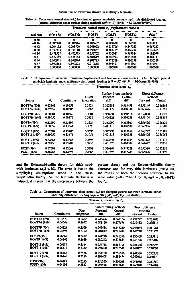
Estimation of tramwu~ stresses in multilayer laminates 363
Table 14. Transverse normal stress (8,) for clamped general sandwich laminate uniformly distriiuted loading (central difference exact surface twnB method) wlr = 10) (O/45/-45/30/tore/30/90/0)
Thickness HOST7A HOST7B HOST9 HOST1 1 HOST12 FOST
-0.50 0 -0.46 0.085398 -0.42 0.204132 -0.38 0.339203 -0.34 0.478331
0.41 0.622189 0.44 0.760971 0.41 0.890262 0.50 1.oooooo
0.08%44 0.10&82 0.203720 0.243022 0.338 140 0.398867 0.480593 0.556702 0.624164 0.684619 0.762994 0.802725 0.890873 0.910865 l.OoOoOO l.OooOOO
0 0 0 0.089628 0.106582 0.018231 0.216715 0.247263 0.057263 0.361769 0.40625 1 0.116415 0.510081 0.569144 0.192099 0.642993 0.6925% 0.404741 0.771268 0.806239 0.620268 0.893421 0.911901 0.819961 l.OooooO l.OOOOOO l.OoowO
Transveme normal stress 8, (displacement models)
Table 15. Comparison of maximum transverse disphwcment and transverse shear stress (f,) for clamped general sandwich laminate under uniformly distributed loading (a/h = 50) (O/45/-45/3O/core/30/90/0)
Transverse &ear stress f_
source Constitutive Direct
integration
Surface fittiog methcds Forward Central
diK diff.
Direct difference methods
Forward Central
HOST’IA (9N) 0.62662 0.10256 0.3524 0.362388 0.353498 0.355146 0.346266 HOST7A (16N) 0.59857 0.10606 0.3888 0.411172 0.400344 0.360626 0.351558
HOST7B (9N) 0.60301 0.10668 0.3504 0.358934 0.350516 0.352030 0.343620 HOST7B (16N) 0.59950 0.10876 0.3836 0.406526 0.396038 0.357104 0.348314
HOST9 (9N) 0.62990 0.13594 0.3524 0.362790 0.353800 0.3554% 0.346520 HOST9 (16N) 0.60059 0.13544 0.3890 0.411410 0.400508 0.365936 0.351808
HOST1 l(9N) 0.62684 0.13706 0.3596 0.3722% 0.363166 0.360222 0.351188 HOST11 (16N) 0.59750 0.13676 0.3956 0.421338 0.410338 0.364406 0.355268
HOST12 (9N) 0.62684 0.13888 0.35% 0.372344 0.363154 0.360222 0.351172 HOSTl2(16N) 0.59750 0.13902 0.3956 0.401370 0.410304 0.364422 0.355256
FOST (9N) 0.57508 0.12068 0.3498 0.356864 0.348728 0.350380 0.342250 FOST (16N) 0.56766 0.12394 0.3866 0.407498 0.397234 0.355806 0.3471%
and the Reissner/Mindlin theory for thick sand- present theory and the Reissner/Mindlin theory with laminates (a/h Q 10). The error is due to the decreases and for very thin laminates (a/h 2 50), simplifying assumptions made in the Reiss- the results of both the theories converge to the ner/Mindlin theory. As the laminate thickness is same value (- 8.70297PD for &, and -0.81746PD reduced, it is seen that the discrepancy between the for Z,).
Table 16. Comparison of transverse shear stress &v,) for clamped general sandwich laminate under uniformly distributed loading (a/h = 50) (O/45/ - 45/3O/c4we/30/90/0)
Transverse shear stress iw
SOUICC
HOST7A (9M
Direct Constitutive integration
0.04570 0.2432 HOSIYA (16N> 0.04548 0.2692
HOST7B (9N) 0.04324 0.2500 HO!JT7B (16N) 0.04398 0.2772
HOST9 (9N) 0.06667 0.2422 HOST9(16N) 0.06346 0.2680
HOST1 l(9N) 0.06684 0.2534 HOST11 (UN) 0.06372 0.2780
HOST12 (9N) 0.06746 6.2534 HOST12 (16N) 0.06446 0.2780
Surface fitting methods Forward Central
diff. diff.
0.2434% 0.242154 0.281160 0.279576
0.249488 0.248230 0.289012 0.287490
0.242710 0.241350 0.280242 0.278644
0.257768 0.256116 0.294420 0.292546
0.257768 0.256056 0.294408 0.292474
Direct difference methods
Forward Central
0.237242 0.235908 0.237432 0.236114
0.243034 0.241784 0.243248 0.241974
0.236468 0.235116 0.236728 0.235402
0.244336 0.242798 0.242052 0.240594
0.244336 0.242756 0.242052 0.240570
I 0.04098 0.2530 0.251250 0.250008 0.245086 0.243850 FOST (16N) 0.04198 0.2842 0.293978 0.292448 0.246078 0.244802

T. KANT and B. S. MANJIJNATHA
0. ---PmaeatFD-Emu -FNnntcD-Bmd
) 000 Renntmreulute~ 000 FOSTPD-BSFM
0.30 - : AAA FoSTCD-B.$m. I I I
0.10 - I I
-0.10 - 7, I I
I I I I
Fig. 10. Variation of transverse shear stress (t, ) through the thickness of a clamped general sandwich laminate under uniformly distributed loading (a/h = 10) (HOST9)(16N).
0.50
0.30 - - - Present Dimet Intog. - Re8uuBSFM ooo FOSTESFM
Q*
IJ \
0.10 \ \ \ \
0.30 I 0 ,
0 &-@ ,
0 / cc*
0.50 - -
Fig. 12. Variation of transverse normal stress (uz ) through the thickness of a clamped general sandwich laminate under uniformly distributed loading (o/h = 10) (HOST9)(16N).
The transverse normal stress variation distinctly These theories assume the realistic non-linear vari-
shows the difference between the present higher-order ation of displacements. The numerical results for theory and the Reissner/Mindlin theory (Fig. 12). As displacement and transverse stresses when compared
seen in previous problems, here also the exact surface with the available elasticity and other closed-form fitting method gives a good estimate of the stress solutions show good agreement. The convergence has compared to the direct integration method. The been demonstrated in all cases in the limit when a/h in-plane displacement variation clearly brings out ratio tends to be large. The results obtained by models the realistic cubic variation of the cross-section of the when zero top and bottom shear conditions are not laminate for model HOST9 (Fig. 13). But the Reiss- enforced are close to the elasticity and other closed- ner/Mindlin theory gives an unrealistic straight line form solutions compared to the models when this variation through the thickness of the laminate. condition is enforced especially for thick laminates.
CONCLUSIONS
It has been demonstrated in this paper that the versatile finite element analysis of the Co higher-order theories can accurately predict the complex transverse stresses and deformation behaviour of composite and sandwich laminates subjected to a variety of loadings.
0.30 - I me_ Resent FD-ESPM -
I PresentmEsFM
000 I RolaatDimctIntq
I A A A POST FD-ESFM 0.10 - 1 0 0 0 POST CD-ESFM.
I
c 0’ I I I I
0.10 0.20 I 0.30 -0.10 - 7 I
Y’ I I I I
-0.30 - 1 t3
- 03
Fig. 11. Variation of transverse shear stress (To: ) through the thickness of a clamped general sandwich laminate under uniformly distributed loading (a/h = 10) (HOST9)(16N).
- HOST12(16N) ___ POST
I I I . I I I - 15 -10 -51 \ lo 5 10 15
-b t 4, Inplane displacement
g ‘1
2 -“.3 ‘\I k \ - 0.50 \
Fig. 13. Variation of in-plane displacement through the thickness of a clamped general sandwich laminate under uniformly distributed loading (a/h = 10) (HOST9)(16N).
The delamination stress evaluation using the finite element method under any type of loading conditions is not going to be a simple job in composite and sandwich laminates. This is due to the higher-order numerical differentiation (third derivative) in the longitudinal direction associated with the integration of the elasticity equilibrium equations in the thickness direction. The use of the proposed ne.w methods and
Estimation of transverse stresses in multilayer laminates 365
cubic Co elements seems to have given fairly accurate estimates of these stresses.
The proposed exact surface fitting method can be efficiently employed for evaluating the transverse shear stresses and central difference exact surface fitting method is recommended for evaluation of transverse normal stress. The results obtained by these methods are close to the available closed-form elasticity solution when compared to direct inte- gration and finite difference methods. The results of transverse shear and normal stresses are also pre- sented for new problems where elasticity solutions are not available with a view to provide data for future reference.
The displacements and transverse stresses obtained by model HOST9 (nine degrees of freedom per node) are close to the closed-form elasticity solutions com- pared to the other models. Thus, this model is recommended for general composite laminates. But for sandwich and highly anisotropic composite lami- nate, model HOST12 is recommended as this model considers the three-dimensional material properties and non-linear variation of transverse displacement through the thickness of the laminate.
Acknowledgement-Partial support of this research by the Aeronautics Research and Development Board, Ministry of Defence, Government of India through its Grants Aero/RD-134/100/10/88-89/534 is gratefully acknowledged.
1.
2.
3.
4.
5.
6.
7.
8.
9.
10.
REFERENCES
R. M. Jones, Mechanics of Composite Materials. McGraw-Hill, New York (1975). E. Reissner, The effect of transverse shear deformation on the bending of elastic plates. ASME J. AnnI. Mech. 12, A69-A77 71945). -
__
R. D. Mindlin, Influence of rotatory inertia and shear deformation on flexural motions of isotropic elastic plates. ASME J. Appl. Mech. 18, 31-38 (1951). E. Reissner, On transverse bending of plates, including the effect of transverse shear deformation. ht. J. Solids Struct. 11, 569-573 (1975). K. H. Lo, R. M. Christensen and E. M. Wu, A high order theory of plate deformation-Part 2: Laminated plates. ASME J. Appl. Mech. 44, 669676 (1977). K. H. Lo, R. M. Christensen and E. M. Wu, Stress solution determination for high order plate theory. ht. J. Solids Struct. 14, 655662 (1978). T. Kant, Numerical analysis of thick plates. Comput. Meth. appl. Mech. Engng 31, l-18 (1982). T. Kant, D. R. J. Owen and 0. C. Zienkiewicz, A refined higher-order Co nlate bending element. Contour. Struct. 1% 177-183 (19i2). - B. N. Pandya and T. Kant, Finite element stress analysis of laminated composite plates using a higher-order displacement model. Compos. Sci. Technol. 32, 137-155 (1988). B. N. Pandya and T. Kant, A simple finite element formulation of a higher-order theory for unsymmetri-
11.
12.
13.
14.
15.
16.
17.
18.
19.
20.
21.
22.
23.
24.
25.
26.
27.
28.
29.
30.
31.
tally laminated composite plates. Compos. Struct. 9, 215-246 (1988). B. N. Pandya and T. Kant, Higher-order shear deform- able theories for flexure of sandwich plates-finite el- ement evaluations. ht. J. Solids Struct. IA. 1267-1286 (1988). T. Kant and B. S. Manjunatha, An unsymmetric FRC laminate Co finite element model with twelve degrees of freedom per node. Int. J. Engng Comput. 5, %lO-308 (1988). T. Kant and B. S. Manjunatha, Higher-order theories for symmetric and tmsymmetric fibre reinforced com- posite beams with Co finite elements. Finite Elements in A~lpis and Design 6, 303-320 (1990). J. N. Reddy, A simple higher-order theory for lami- nated composite plates. ASME J. Appl. Mech. 51, 745-752 (1984). N. D. Phan and J. N. Reddy, Analysis of laminated composite plates using a higher-order shear deformable theory. Int. J. Numer. Meth. Engng 21, 2201-2219 (1985). N. S. Pucha and J. N. Reddy, A refined mixed shear flexible Jinite element for the nonlinear analysis of laminated plates. Comput. Struct. 22, 529-538 (1986). M. V. V. Mm-thy, An improved transverse shear defor- mation theory for laminated anisotropic plates. NASA technical paper-1903 (1981). M. Levinson, A new rectangular beam theory. J. Sound Vibr. 74, 81-87 (1981). J. G. Ren and E. Hinton, The finite element analysis of homogeneous and laminated composite plates using a simple higher-order theory. Commun. appi. Numer. Meth. 12, 217-228 (1986). J. J. Engblom and 0. 0. Ochoa, Through the thickness stress predictions for laminated plates of advanced composite materials. Int. J. Numer. Meth. Engng 21, 1759-1776 (1985). J. J. Engblom and 0. 0. Ochoa, Finite element formu- lation including interlaminar stress calculations. Com- put. Struct. 23, 241-249 (1986). N. J. Pagano, Exact solution for composite laminates in cylindrical bending. J. Compos. Mater. 3, 398-41 I (1969). N. J. Pagano, Exact solution for rectangular bidircc- tional composites and sandwich plates. J. Compos. Mater. 4, 20-34 (1970). J. G. Ren, A new theory of laminated plate. Compos. Sci. Technol. 26, 225-239 (1986). J. G. Ren, Bending of a simply supported, antisymmet- rically laminated rectangular plate under transverse loading. Compos. Sci. Technol. 28, 231-243 (1987). J. M. Whitney, Bending-extensional coupling in lami- nated plates under transverse loading. J. Compos. Mater. 3, 20-28 (1969). G. J. Turvey, Bending of laterally loaded, simply sup- ported, moderately thick, antisymmetrically la~minated rectangular plate. Fibre Sci. Technol. 10, 21 l-232 (1977). H. G. Allen, Analysis and Design of Structural Sandwich Panels. Pergamon Press, London (1969). D. S. Cairns and P. A. Lagace, Thick composite plates subjected to later loading- ASME J. Appi. Me&. 54, 61 l-616 (1987). M. G. Salvadori and M. L. Baron, Numerical Methoak in Engineering. Prentice-Hall, Englewood Cliffs, NJ (1961). S. P. Timoshenko and J. N. Goodier, Theory of Elasticity, 3rd Edn. McGraw-Hill, New York (1982).