omnicare electric shower - contour-showers.co.uk
TRANSCRIPT

Installation and operating
instructionsINSTALLERS PLEASE NOTE THESE INSTRUCTIONS ARE
TO BE LEFT WITH THE USER
2181515A - June 2017UK Patent Application
Patent Pending GB 2522438 A”EC Registered Design No.
002418376 - 00001 to 00009
Omnicare electric shower
The showerhead and hose supplied with this product are a safety critical part of your shower. Failure to use genuine Triton parts
may cause injury and invalidate your guarantee.
22
IMPORTANT - GENERAL GUIDANCE NOTES
1 GENERAL1.1 Isolate the electrical and water supplies before
removing the cover.1.2 Read all of these instructions and retain them
for later use.1.3 DO NOT take risks with plumbing or electrical
equipment.1.4 Isolate electrical and water supplies before
proceeding with the installation.1.5 The unit must be mounted onto the finished
wall surface (on top of the tiles). DO NOT tile up to or seal around ANY PART of the unit using silicone sealer after fixing to the wall. Special care must be taken NOT TO BLOCK OR SEAL ANY PRD VENTS ON THE UNIT.
1.6 Contact Customer Service (see back page), if any of the following occur:
a) If it is intended to operate the shower at pressures above the maximum or below the minimum stated.
b) If the unit shows a distinct change in performance.c) If the shower is frozen.
1.7 If it is intended to operate the shower in areas of hard water (above 200 ppm temporary hardness), a scale inhibitor may have to be fitted. For advice on the Scale Inhibitor, contact Customer Service.
1.8 The showerhead must be cleaned regularly with descalent to remove scale and debris, otherwise restrictions to the flow on the outlet of the unit will result in higher temperatures and could also cause the (PRD) Pressure Relief Device in the unit to operate.
1.9 This product is not suitable for mounting into steam rooms or steam cubicles.
2 PLUMBING2.1 The plumbing installation must comply with
Water Regulations, Building Regulations or any particular regulations as specified by Local Water Company or Water Undertakers and should be in accordance with BS EN 806.
2.2 The supply pipe must be flushed to clear debris before connecting to the shower unit.
2.3 DO NOT solder pipes or fittings within 300mm of the shower unit, as heat can transfer along the pipework and damage components.
2.4 DO NOT fit any form of outlet flow control as the outlet acts as a vent for the heater can.
2.5 DO NOT use excessive force when making connections to the flexible hose or showerhead, finger tight is sufficient.
2.6 All plumbing connections must be completed before making the electrical connections.
2.7 This appliance MUST not be connected to the inlet supply by a hose-set.
3 ELECTRICAL3.1 The installation must comply with BS 7671
‘Requirements for electrical installations’ (IEE wiring regulations), building regulations or any particular regulations as specified by the local Electrical Supply Company.
3.2 This appliance MUST be earthed.3.3 In accordance with ‘The Plugs and Sockets etc.
(Safety) Regulations 1994’, this appliance is intended to be permanently connected to the fixed wiring of the electrical mains system.
3.4 Make sure all electrical connections are tight to prevent overheating.
3.5 A 30mA residual current device (RCD) MUST be installed in all UK electric and pumped shower circuits. This may be part of the consumer unit or a separate unit.
3.6 Switch off immediately at isolating switch if water ceases to flow during use.
3.7 Other electrical equipment i.e. extractor fans, pumps must not be connected to the circuits within the unit.
3.8 Switch off at isolating switch when not in use. This is a safety procedure recommended with all electrical appliances.
3.9 As with all electrical appliances it is recommended to have the shower and installation checked at least every two years by a competent electrician to ensure there is no deterioration due to age and usage.
WARNING
.
This appliance can be used by children aged from 8 years and above and persons with reduced physical, sensory or mental
capabilities or lack of experience or knowledge if they have been given supervision or instruction concerning use of the appliance
in a safe way and understand the hazards involved. Children may not play with the appliance. Cleaning and user maintenance shall
not be made by children without supervision.
3
INTRODUCTION - PLEASE READ
Products manufactured by Triton are safe and without risk provided they are installed, used and maintained in good working order in accordance with our instructions and recommendations.
WARNING: DO NOT operate shower if frozen, or suspected of being frozen. It must thaw out before using.
DO NOT operate the unit if the showerhead or spray hose becomes damaged.
DO NOT restrict flow out of shower by placing showerhead in direct contact with your body.
DO NOT operate the shower if water ceases to flow during use or if water has entered inside
the unit because of an incorrectly fitted cover.
This book contains all the necessary fitting and operating instructions for your electric shower.
Care taken during the installation will provide a long, trouble-free life from your shower.
IMPORTANT SAFETY INFORMATION
Triton recommend watching the short online *videos that cover electric shower basics before your installation - *(videos may not show the exact model purchased).
• What is an electric shower?
• Electrical requirements for electric showers
• Plumbing requirements for electric showers
• Kilowatt ratings explained
To view these videos visit: www.tritonshowers.co.uk/triton-products/product-videos.aspx
PLEASE USE THE FOLLOWING CHECK LIST TO AID YOUR INSTALLATION
Product specifications .............................................................................................. 1
Product entry points and dimensions ....................................................................... 2
Check that the electric supply will satisfy requirements ............................................ 3
Siting of the shower ................................................................................................. 4
Plumbing installation ............................................................................................... 5
Electrical installation and pumps .............................................................................. 6
Fitting the inlet trims ............................................................................................... 7
Commissioning temperature, DIP switch settings and fitting the cover .................... 8
Familiarise yourself with the user operating instructions ........................................... 9
1
2
3
4
5
6
7
8
9
Tick off as you complete
SECTION
SECTION
SECTION
SECTION
SECTION
SECTION
SECTION
SECTION
SECTION
4
GENERAL ADVICE TO USERS
INTRODUCTION
This book contains all the necessary fitting and
operating instructions for your Triton electric
shower.
Take time to read this book thoroughly and
familiarise yourself with all instructions before
commencing installation. Please keep it for future
reference.
The shower installation must be carried out by a
suitably qualified person and in the sequence of
this instruction book.
Care taken during the installation will provide a
long, trouble-free life from your shower.
SPECIFICATIONS
Electrical
Nominal power Nominal power
rating at 240V rating at 230V
8.5kW – (40A MCB rating) 7.8kW – (40A MCB rating)
9.5kW – (40A MCB rating) 8.7kW – (40A MCB rating)
Water
Inlet connection – 15 mm diameter.
Outlet connection – ½” BSP male thread.
Entry Points
Water – Right: Top, bottom back, bottom.
Cable – Right: Top, bottom back, bottom.
Left: Top
Materials
Backplate, cover, controls, showerhead – ABS.
Sprayplate – Acetal.
Elements – Minerally insulated corrosion resistant
metal sheathing.
Dimensions
Height − 361 mm
Width − 245 mm
Depth − 121 mm
Standards and Approvals
Splashproof rating IP25.
Complies with the requirements of current British
and European safety standards for household and
similar electrical appliances.
Complies with requirements of the British
Electrotechnical Approvals Board (BEAB) and
BEAB CARE mark (BEAB).
Meets with Compliance with European
Community Directives (CE).
ADVICE TO USERS
The following points will help you understand
how the shower operates:
a) Temperature/flow rate
The temperature control can be adjusted to
provide shower temperatures between 35°C
and 47°C.
Alternatively, adjusting a temperature
stop mechanism inside the unit to 41°C
or 43°C maximum can restrict the shower
temperature.
Important: To comply with BEAB care
mark requirements the unit must not be
able to run hotter than 41°C (this is used in
healthcare or special needs environments).
The Omnicare thermostatic unit is factory
set at 47°C (see page 17) on how to adjust
the MAXIMUM temperature stop to 41°C
At a selected showering temperature the unit
will provide the optimum flow rate possible.
Note the maximum flow rate for the given
temperature will be greater in the summer
than in the winter because of the variance in
the ambient mains water supply.
Should water pressure/flow to the shower be
insufficient for optimum performance then
the unit will operate at a reduced power level
and provide the highest flow rate possible for
the given shower temperature.
b) Temperature stabilisation
The shower will maintain temperature in
accordance with the BEAB care mark.
If ever the water becomes too hot, and you
cannot obtain cooler water, first check that
the sprayplate in the showerhead has not
become blocked.
DO NOT place items such as soap or shampoo
bottles on top of the unit. Liquid could seep
through the joint between the cover and backplate,
and possibly damage the sealing rubber.
Important: When first installed the unit
will be empty. It is essential the unit should
contain water before the elements are
switched on. It is vital that the commissioning
procedure is followed. Failure to carry out this
operation will result in damage to the unit
and will invalidate the guarantee.

5
MAIN COMPONENTS
No
te:
Wir
es
have
not
been
sh
ow
n f
or
reaso
ns
of
clari
ty.
1
Inside the unit (fig.A)
1. Top cable and pipe entry
2. Top left cable entry
3. Wall screw fixings
4. Cover screw fixings
5. Thermal safety cut-out
6. Power printed circuit board
7. Can and element assembly
8. Flow sensor
9. Thermostatic valve &
maximum temperature selector
10. Terminal block (L & N)
11. Earth connection
12. Solenoid valve
13. Water inlet
14. Pressure relief device
(PRD)
15. Shower outlet
16. Splash guard
Inside the unit (Fig.A)
4
3
5
6
3
3
4
7
8
9
10
11
12
13
14
15
16
4
2
6
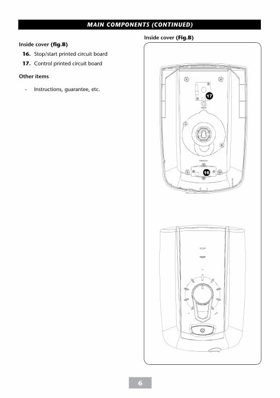
Inside cover (fig.B)
16. Stop/start printed circuit board
17. Control printed circuit board
Other items
- Instructions, guarantee, etc.
Inside cover (Fig.B)
17
16
MAIN COMPONENTS (CONTINUED)
7
To check the product suitability for commercial and multiple installations, please contact Triton’s specification advisory service before installation. Please see back of book for contact information.
E mail: [email protected]
Contents Page
Important safety information .......................................................... 2
Introduction .........................................................................3
General advice to users ................................................................... 4
Main components ....................................................................... 5 - 6
Specifications .................................................................................. 8
Dimensions & entry points ............................................................. 9
Electrical requirements ............................................................... 10 - 11
Siting of the shower ................................................................... 12 - 13
Plumbing installation ................................................................. 15 - 16
Electrical installation and pumps ................................................ 17 - 20
Fitting the inlet trims ..................................................................... 21
Commissioning .......................................................................... 22 - 27
Operating instructions ................................................................... 28
Adjusting the Maximum temperature stop
35°C to 47°C - Standard showering ..................................................24- 25
BEAB Care (41°C) ...................................................................... 26
PCB Dip Switch settings ................................................................. 27
Operating functions ....................................................................... 28
Instructions for installers and service engineers only ....................... 29
Spare parts ................................................................................ 30 - 31
Fault finding .............................................................................. 32 - 33
In-service Testing ....................................................................... 34 - 36
UK Service policy /Guarantee, etc. ........................................... rear cover
Omnicare
Please read this book thoroughly and familiarise yourself with all
instructions before commencing installation and keep it for future reference.
The shower installation MUST be carried out by a suitably qualified person, in the
sequence of this instruction book.
8
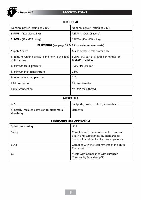
SPECIFICATIONScheck list1SECTION
ELECTRICAL
Nominal power - rating at 240V Nominal power - rating at 230V
8.5kW – (40A MCB rating) 7.8kW – (40A MCB rating)
9.5kW – (40A MCB rating) 8.7kW – (40A MCB rating)
PLUMBING (see page 14 & 15 for water requirements)
Supply Source Mains pressure cold water only
Minimum running pressure and flow to the inlet
of the shower
50kPa (0.5 bar) at 8 litres per minute for
8.5kW & 9.5kW
Maximum static pressure 1000 kPa (10 bar)
Maximum inlet temperature 28°C
Minimum inlet temperature 2°C
Inlet connection 15mm diameter
Outlet connection ½” BSP male thread
MATERIALS
ABS Backplate, cover, controls, showerhead
Minerally insulated corrosion resistant metal
sheathing
Elements
STANDARDS and APPROVALS
Splashproof rating IP25
Safety Complies with the requirements of current
British and European safety standards for
household and similar electrical appliances
BEAB Complies with the requirements of the BEAB
Care mark
CE Meets with Compliance with European
Community Directives (CE)
9
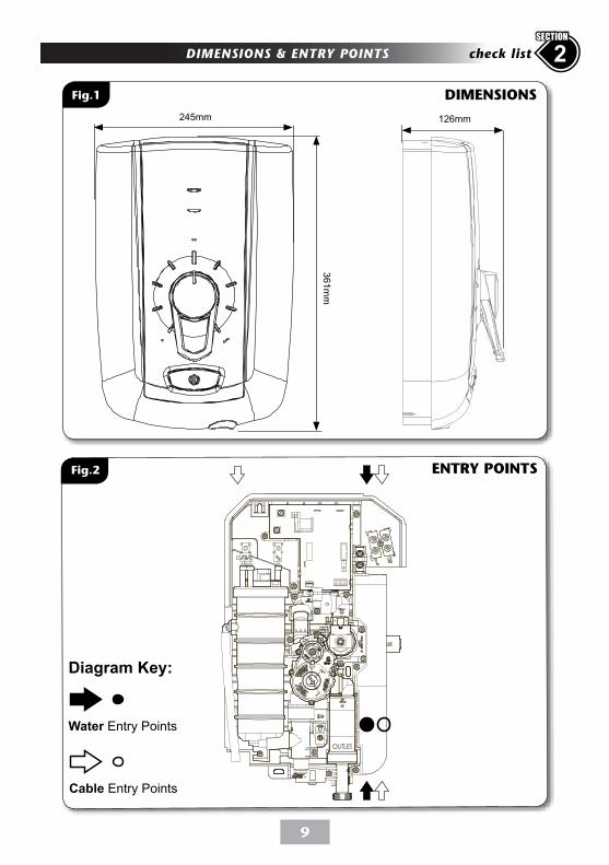
DIMENSIONS & ENTRY POINTS 2check list
SECTION
Fig.1 DIMENSIONS
Fig.2 ENTRY POINTS
Diagram Key:
Water Entry Points
Cable Entry Points
126mm245mm
361m
m
10
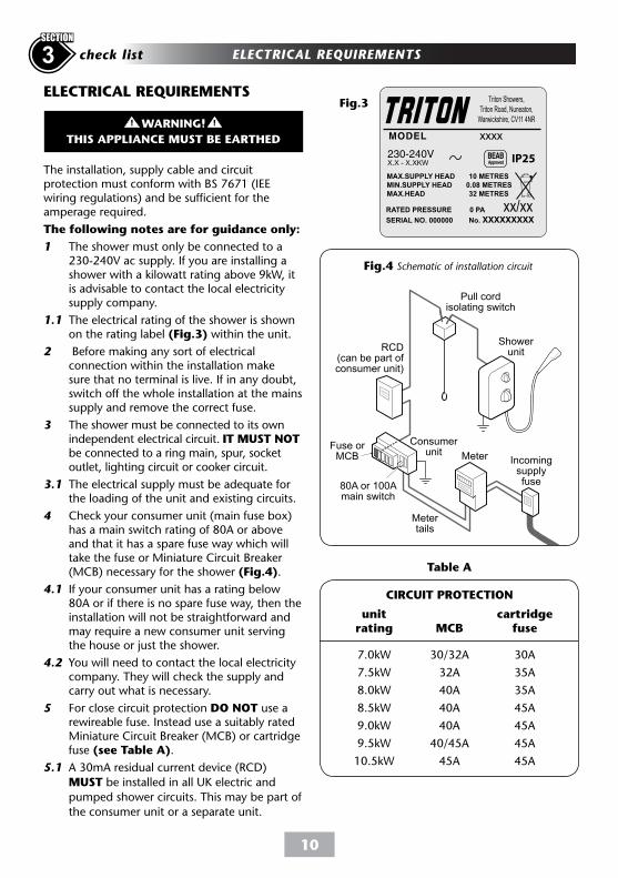
W-006-AWARNING!
THIS APPLIANCE MUST BE EARTHED
Meter Incomingsupplyfuse
Metertails
Consumerunit
Pull cordisolating switch
Showerunit
Fuse orMCB
RCD(can be part ofconsumer unit)
80A or 100Amain switch
Table A
MCB
30/32A
32A
40A
40A
40A
40/45A
45A
cartridgefuse
30A
35A
35A
45A
45A
45A
45A
unit rating
7.0kW
7.5kW
8.0kW
8.5kW
9.0kW
9.5kW
10.5kW
CIRCUIT PROTECTION
Fig.4 Schematic of installation circuit
ELECTRICAL REQUIREMENTS
The installation, supply cable and circuit protection must conform with BS 7671 (IEE wiring regulations) and be sufficient for the amperage required.
The following notes are for guidance only:
1 The shower must only be connected to a 230-240V ac supply. If you are installing a shower with a kilowatt rating above 9kW, it is advisable to contact the local electricity supply company.
1.1 The electrical rating of the shower is shown on the rating label (Fig.3) within the unit.
2 Before making any sort of electrical connection within the installation make sure that no terminal is live. If in any doubt, switch off the whole installation at the mains supply and remove the correct fuse.
3 The shower must be connected to its own independent electrical circuit. IT MUST NOT be connected to a ring main, spur, socket outlet, lighting circuit or cooker circuit.
3.1 The electrical supply must be adequate for the loading of the unit and existing circuits.
4 Check your consumer unit (main fuse box) has a main switch rating of 80A or above and that it has a spare fuse way which will take the fuse or Miniature Circuit Breaker (MCB) necessary for the shower (Fig.4).
4.1 If your consumer unit has a rating below 80A or if there is no spare fuse way, then the installation will not be straightforward and may require a new consumer unit serving the house or just the shower.
4.2 You will need to contact the local electricity company. They will check the supply and carry out what is necessary.
5 For close circuit protection DO NOT use a rewireable fuse. Instead use a suitably rated Miniature Circuit Breaker (MCB) or cartridge fuse (see Table A).
5.1 A 30mA residual current device (RCD)
MUST be installed in all UK electric and
pumped shower circuits. This may be part of
the consumer unit or a separate unit.
Triton Showers,
Triton Road, Nuneaton,
Warwickshire, CV11 4NR
xxxx
Fig.3
Shepperton Park,
Triton Road, Nuneaton,
Warwickshire, CV11 4NR
Triton Showers,
Triton Road, Nuneaton,
Warwickshire, CV11 4NR
xxxx
IP25
Meter Incomingsupplyfuse
Metertails
Consumerunit
Pull cordisolating switch
Showerunit
Fuse orMCB
RCD(can be part ofconsumer unit)
80A or 100Amain switch
Triton Showers,
Triton Road, Nuneaton,
Warwickshire, CV11 4NR
ELECTRICAL REQUIREMENTS3 check list
SECTION
11
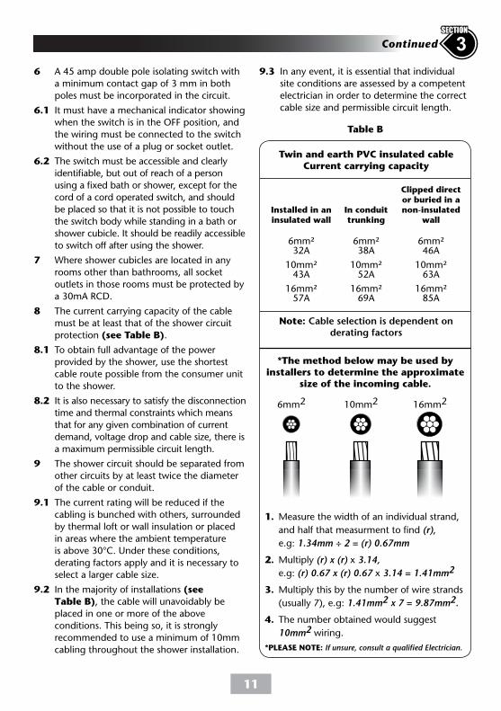
Table B
Note: Cable selection is dependent on derating factors
Twin and earth PVC insulated cableCurrent carrying capacity
In conduittrunking
6mm²38A
10mm²52A
16mm²69A
Installed in an insulated wall
6mm²32A
10mm²43A
16mm²57A
Clipped director buried in a non-insulated
wall
6mm²46A
10mm²63A
16mm²85A
6mm2 10mm2 16mm2
*The method below may be used byinstallers to determine the approximate
size of the incoming cable.
1. Measure the width of an individual strand,
and half that measurment to find (r),
e.g: 1.34mm ÷ 2 = (r) 0.67mm
2. Multiply (r) x (r) x 3.14,
e.g: (r) 0.67 x (r) 0.67 x 3.14 = 1.41mm2
3. Multiply this by the number of wire strands
(usually 7), e.g: 1.41mm2 x 7 = 9.87mm2.
4. The number obtained would suggest
10mm2 wiring.
*PLEASE NOTE: If unsure, consult a qualified Electrician.
6 A 45 amp double pole isolating switch with
a minimum contact gap of 3 mm in both
poles must be incorporated in the circuit.
6.1 It must have a mechanical indicator showing
when the switch is in the OFF position, and
the wiring must be connected to the switch
without the use of a plug or socket outlet.
6.2 The switch must be accessible and clearly
able, but out of reach of a person
u xed bath or shower, except for the
cord of a cord operated switch, and should
be placed so that it is not possible to touch
the switch body while standing in a bath or
shower cubicle. It should be readily accessible
to switch off after using the shower.
7 Where shower cubicles are located in any
rooms other than bathrooms, all socket
outlets in those rooms must be protected by
a 30mA RCD.
8 The current carrying capacity of the cable
must be at least that of the shower circuit
protection (see Table B).
8.1 To obtain full advantage of the power
provided by the shower, use the shortest
cable route possible from the consumer unit
to the shower.
8.2 It is also necessary to satisfy the disconnection
time and thermal constraints which means
that for any given combination of current
demand, voltage drop and cable size, there is
a maximum permissible circuit length.
9 The shower circuit should be separated from
other circuits by at least twice the diameter
of the cable or conduit.
9.1 The current rating will be reduced if the
cabling is bunched with others, surrounded
by thermal loft or wall insulation or placed
in areas where the ambient temperature
is above 30°C. Under these conditions,
derating factors apply and it is necessary to
select a larger cable size.
9.2 In the majority of installations (see
Table B), the cable will unavoidably be
placed in one or more of the above
conditions. This being so, it is strongly
recommended to use a minimum of 10mm
cabling throughout the shower installation.
9.3 In any event, it is essential that individual
site conditions are assessed by a competent
electrician in order to determine the correct
cable size and permissible circuit length.
3Continued
SECTION
12
* Recommended minimum running pressure
and flow at the shower inlet 100kPa (1 bar)
at 8 litres per minute for full performance.
Note: if the recommended running pressure
and flow is not available there will be a
noticeable reduction in flow from the
showerhead.
If it is intended to operate the shower at
pressures above the maximum or below the
minimum stated, contact Customer Service for
advice.
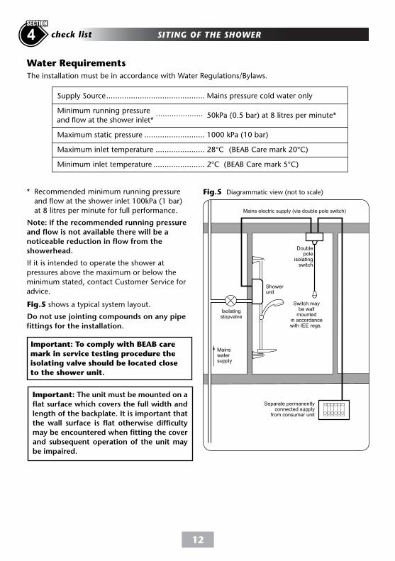
Isolatingstopvalve
Mainswatersupply
Showerunit
Switch maybe wallmounted
in accordancewith IEE regs.
Mains electric supply (via double pole switch)
Doublepole
isolatingswitch
Separate permanentlyconnected supply
from consumer unit
Fig.5 Diagrammatic view (not to scale)
The installation must be in accordance with Water Regulations/Bylaws.
Important: To comply with BEAB care
mark in service testing procedure the
isolating valve should be located close
to the shower unit.
Water Requirements
Supply Source ............................................ Mains pressure cold water only
Minimum running pressure 50kPa (0.5 bar) at 8 litres per minute*
and flow at the shower inlet*
Maximum static pressure ........................... 1000 kPa (10 bar)
Maximum inlet temperature ...................... 28°C (BEAB Care mark 20°C)
Minimum inlet temperature ....................... 2°C (BEAB Care mark 5°C)
.....................
Fig.5 shows a typical system layout.
Do not use jointing compounds on any pipe
fittings for the installation.
I-002-A
Important: The unit must be mounted on a
flat surface which covers the full width and
length of the backplate. It is important that
the wall surface is flat otherwise difficulty
may be encountered when fitting the cover
and subsequent operation of the unit may
be impaired.
SITING OF THE SHOWER4 check list
SECTION
13
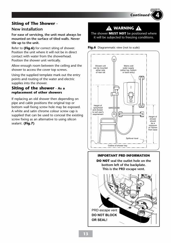
Outline of shower tray
Mains coldwater supply
(either top, bottom or back entry)
Shower unitcan be mounted
either sideof riser rail
Height ofshowershouldbe a
minimumof 750mmfrom base
Spillover level
Height of sprayhead
and shower to suit user'srequirement
Fig.6 Diagrammatic view (not to scale)
Siting of The Shower -
New installation
For ease of servicing, the unit must always be
mounted on the surface of tiled walls. Never
tile up to the unit.
Refer to (Fig.6) for correct siting of shower.
Position the unit where it will not be in direct
contact with water from the showerhead.
Position the shower unit vertically.
Allow enough room between the ceiling and the
shower to access the cover top screws.
Using the supplied template mark out the entry
points and routing of the water and electric
supplies into the shower.
Siting of the shower - As a
replacement of other showers
If replacing an old shower then depending on
pipe and cable positions the original top or
bottom wall fixing screw hole may be exposed.
A white and satin chrome colour screw cap is
supplied that can be used to conceal the existing
screw fixing as an alternative to using silicon
sealant. (Fig.7)
WARNINGThe shower MUST NOT be positioned where
it will be subjected to freezing conditions.
4Continued
SECTION
IMPORTANT PRD INFORMATION
DO NOT seal the outlet hole on the
bottom left of the backplate.
This is the PRD escape vent.
PRD escape vent
DO NOT BLOCK
OR SEAL!
14
Omnicare
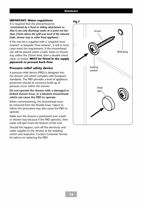
IMPORTANT: Water regulations
It is required that the showerhead be
‘constrained by a fixed or sliding attachment so
that it can only discharge water at a point not less
than 25mm above the spill-over level of the relevant
bath, shower tray or other fixed appliance’.
If the riser kit is supplied with a ‘soapdish hose
retainer’ or bespoke ‘hose retainer’, it will in most
cases meet this requirement. If the showerhead
can still be placed within a bath, basin or shower
tray within the 25mm limit, then a double check
valve, or similar, MUST be fitted in the supply
pipework to prevent back-flow.
Pressure relief safety device
A pressure relief device (PRD) is designed into
the shower unit which complies with European
standards. The PRD provides a level of appliance
protection should an excessive build up of
pressure occur within the shower.
Do not operate the shower with a damaged or
kinked shower hose, or a blocked showerhead
which can cause the PRD to operate.
When commissioning, the showerhead must
be removed from the flexible hose. Failure to
follow this procedure may also cause the PRD to
operate.
Make sure the shower is positioned over a bath
or shower tray because if the PRD operates, then
water will eject from the bottom of the unit.
Should this happen, turn off the electricity and
water supplies to the shower at the isolating
switch and stopvalve. Contact Customer Service
for advice on replacing the PRD.
Fig.7
Wall plug
Sealing
washer
Screw
Snap
cap
15
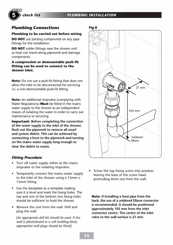
Plumbing Connections Fig.8
Note: If installing a feed pipe from the
back, the use of a soldered Elbow connector
is recommended. It should be positioned
approximately 105 mm from the inlet
connector centre. The centre of the inlet
valve to the wall surface is 21 mm.
105 mm
21 mm
Soldered Elbow
PLUMBING INSTALLATION5 check list
SECTION
Plumbing to be carried out before wiring
DO NOT use jointing compounds on any pipe
fittings for the installation.
DO NOT solder fittings near the shower unit
as heat can travel along pipework and damage
components.
A compression or demountable push-fit
fitting can be used to connect to the
shower inlet.
Note: Do not use a push-fit fitting that does not
allow the inlet to be disconnected for servicing
i.e. a non-demountable push-fit fitting.
Note: An additional stopvalve (complying with
Water Regulations) Must be fitted in the mains
water supply to the shower as an independent
means of isolating the water in order to carry out
maintenance or servicing.
Important: Before completing the connection
of the water supply to the inlet of the shower,
flush out the pipework to remove all swarf
and system debris. This can be achieved by
connecting a hose to the pipework and turning
on the mains water supply long enough to
clear the debris to waste.
Fitting Procedure
• Turn off water supply either at the mains
stopvalve or the isolating stopvalve.
• Temporarily connect the mains water supply
to the inlet of the shower using a 15mm x
15mm fitting.
• Use the backplate as a template making
sure it is level and mark the fixing holes. The
top and one of the bottom two fixing holes
should be sufficient to hold the shower.
• Remove the unit from the wall. Drill and
plug the wall.
(An appropriate drill bit should be used. If the
wall is plasterboard or a soft building block,
appropriate wall plugs should be fitted).
• Screw the top fixing screw into position
leaving the base of the screw head
protruding 6mm out from the wall.
16
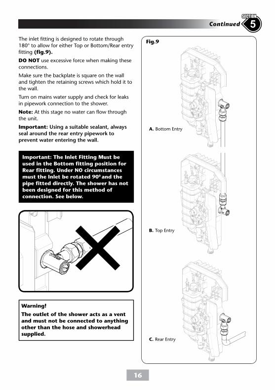
Fig.9
A. Bottom Entry
B. Top Entry
C. Rear Entry
Important: The Inlet Fitting Must be
used in the Bottom fitting position for
Rear fitting. Under NO circumstances
must the Inlet be rotated 900 and the
pipe fitted directly. The shower has not
been designed for this method of
connection. See below.
Warning!
The outlet of the shower acts as a vent
and must not be connected to anything
other than the hose and showerhead
supplied.
5Continued
SECTION
The inlet fitting is designed to rotate through
180° to allow for either Top or Bottom/Rear entry
fitting (fig.9).
DO NOT use excessive force when making these
connections.
Make sure the backplate is square on the wall
and tighten the retaining screws which hold it to
the wall.
Turn on mains water supply and check for leaks
in pipework connection to the shower.
Note: At this stage no water can flow through
the unit.
Important: Using a suitable sealant, always
seal around the rear entry pipework to
prevent water entering the wall.
17
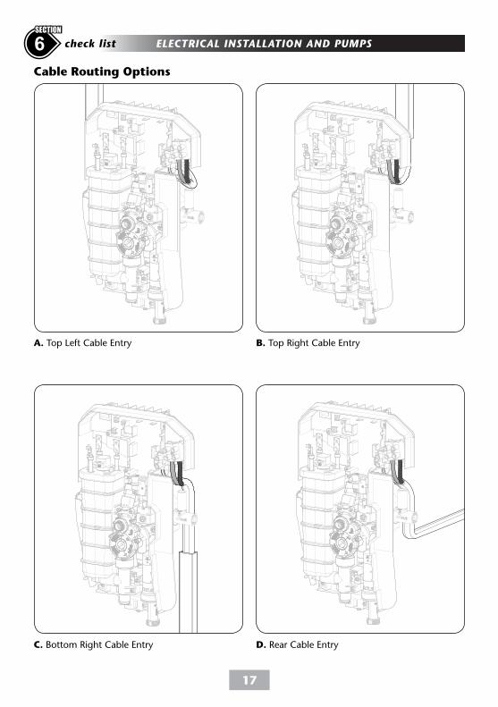
ELECTRICAL INSTALLATION AND PUMPS6 check list
SECTION
A. Top Left Cable Entry B. Top Right Cable Entry
C. Bottom Right Cable Entry D. Rear Cable Entry
Cable Routing Options
18
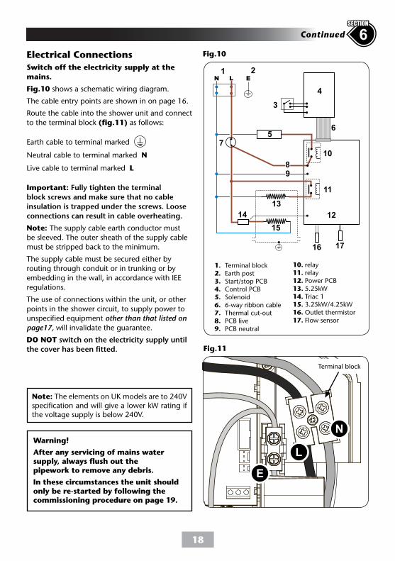
Switch off the electricity supply at the
mains.
Fig.10 shows a schematic wiring diagram.
The cable entry points are shown in on page 16.
Route the cable into the shower unit and connect
to the terminal block (fig.11) as follows:
Earth cable to terminal marked
Neutral cable to terminal marked N
Live cable to terminal marked L
Important: Fully tighten the terminal
block screws and make sure that no cable
insulation is trapped under the screws. Loose
connections can result in cable overheating.
Note: The supply cable earth conductor must
be sleeved. The outer sheath of the supply cable
must be stripped back to the minimum.
The supply cable must be secured either by
routing through conduit or in trunking or by
embedding in the wall, in accordance with IEE
regulations.
The use of connections within the unit, or other
points in the shower circuit, to supply power to
unspecified equipment other than that listed on
page17, will invalidate the guarantee.
DO NOT switch on the electricity supply until
the cover has been fitted.
Fig.10
Fig.11
1. Terminal block 2. Earth post 3. Start/stop PCB 4. Control PCB 5. Solenoid 6. 6-way ribbon cable 7. Thermal cut-out 8. PCB live 9. PCB neutral
10. relay11. relay12. Power PCB13. 5.25kW14. Triac 115. 3.25kW/4.25kW16. Outlet thermistor17. Flow sensor
N-001-ANote: The elements on UK models are to 240V specification and will give a lower kW rating if the voltage supply is below 240V.
Terminal block
E
L
N
LN E
Electrical Connections
Warning!
After any servicing of mains water supply, always flush out the pipework to remove any debris.
In these circumstances the unit should only be re-started by following the commissioning procedure on page 19.
6Continued
SECTION
19
6 Continued
SECTION
Shower Drain Pumps
Drain Pump Compatibility
The Omnicare has been designed to operate
with the most popular drain pumps found on
the market, please take time to fully understand
the type of drain pump being fitted and the
connection required to the electrical shower.
During the installation process the correct DIP
switch configuration must be selected (see Page
24).
Analogue Drain Pump
When the shower is turned on, a signal is sent to
the drain pump electronics telling the pump to
start. When the shower is turned off, a signal is
sent again to the drain pump electronics telling
the pump to stop; generally after a preset time
delay. This type of pump makes no allowance for
the flow rate of the water from the shower, the
‘gulp’ or speed of the pump is fixed.
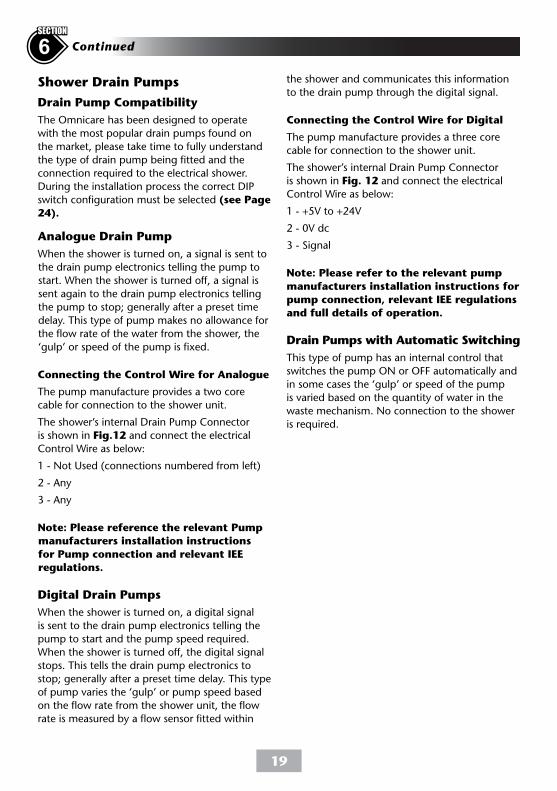
Connecting the Control Wire for Analogue
The pump manufacture provides a two core
cable for connection to the shower unit.
The shower’s internal Drain Pump Connector
is shown in Fig.12 and connect the electrical
Control Wire as below:
1 - Not Used (connections numbered from left)
2 - Any
3 - Any
Note: Please reference the relevant Pump
manufacturers installation instructions
for Pump connection and relevant IEE
regulations.
Digital Drain Pumps
When the shower is turned on, a digital signal
is sent to the drain pump electronics telling the
pump to start and the pump speed required.
When the shower is turned off, the digital signal
stops. This tells the drain pump electronics to
stop; generally after a preset time delay. This type
of pump varies the ‘gulp’ or pump speed based
on the flow rate from the shower unit, the flow
rate is measured by a flow sensor fitted within
the shower and communicates this information
to the drain pump through the digital signal.
Connecting the Control Wire for Digital
The pump manufacture provides a three core
cable for connection to the shower unit.
The shower’s internal Drain Pump Connector
is shown in Fig. 12 and connect the electrical
Control Wire as below:
1 - +5V to +24V
2 - 0V dc
3 - Signal
Note: Please refer to the relevant pump
manufacturers installation instructions for
pump connection, relevant IEE regulations
and full details of operation.
Drain Pumps with Automatic Switching
This type of pump has an internal control that
switches the pump ON or OFF automatically and
in some cases the ‘gulp’ or speed of the pump
is varied based on the quantity of water in the
waste mechanism. No connection to the shower
is required.
20
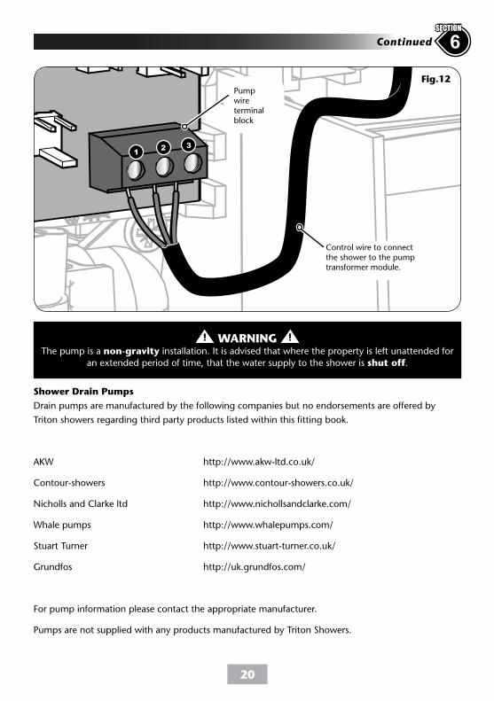
Fig.12
Control wire to connect the shower to the pump transformer module.
Pump wireterminal block
12 3
Shower Drain Pumps
Drain pumps are manufactured by the following companies but no endorsements are offered by
Triton showers regarding third party products listed within this fitting book.
AKW http://www.akw-ltd.co.uk/
Contour-showers http://www.contour-showers.co.uk/
Nicholls and Clarke ltd http://www.nichollsandclarke.com/
Whale pumps http://www.whalepumps.com/
Stuart Turner http://www.stuart-turner.co.uk/
Grundfos http://uk.grundfos.com/
For pump information please contact the appropriate manufacturer.
Pumps are not supplied with any products manufactured by Triton Showers.
WARNINGThe pump is a non-gravity installation. It is advised that where the property is left unattended for
an extended period of time, that the water supply to the shower is shut off.
6Continued
SECTION
21
FITTING THE INLET TRIMS7 check list
SECTION
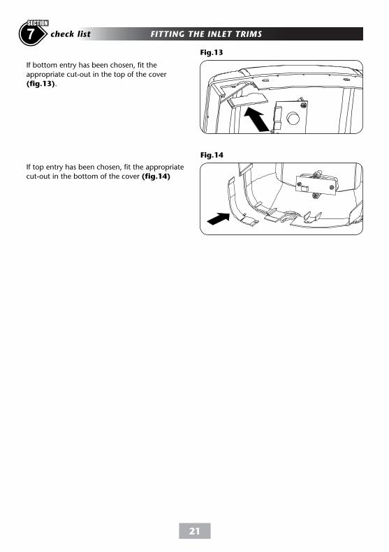
Fig.13
Fig.14
If bottom entry has been chosen, fit the
appropriate cut-out in the top of the cover
(fig.13).
If top entry has been chosen, fit the appropriate
cut-out in the bottom of the cover (fig.14)
22
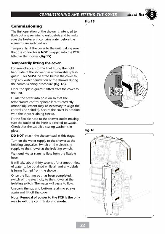
Fig.16
The first operation of the shower is intended to
flush out any remaining unit debris and to make
sure the heater unit contains water before the
elements are switched on.
Temporarily fit the cover to the unit making sure
that the connector is NOT plugged into the PCB
fitted in the shower (fig.15).
Temporarily fitting the cover
For ease of access to the Inlet fitting the right
hand side of the shower has a removable splash
guard. This MUST be fitted before the cover to
stop any water penitration of the shower during
the commissioning procedure (fig.16).
Once the splash guard is fitted offer the cover to
the unit.
Guide the cover into position so that the
temperature control spindle locates correctly
(minor adjustment may be necessary to align the
control and spindle). Secure the cover in position
with the three retaining screws.
Fit the flexible hose to the shower outlet making
sure the outlet of the hose is directed to waste.
Check that the supplied sealing washer is in
place.
DO NOT attach the showerhead at this stage.
Turn on the water supply to the shower at the
isolating stopvalve. Switch on the electricity
supply to the shower at the isolating switch.
Wait until water starts to flow from the flexible
hose.
It will take about thirty seconds for a smooth flow
of water to be obtained while air and any debris
is being flushed from the shower.
Once the flushing out has been completed,
switch off the electricity to the shower at the
isolating switch. The water will cease to flow.
Unscrew the top and bottom retaining screws
again and lift off the cover.
Note: Removal of power to the PCB is the only
way to exit the commissioning mode.
Commissioning
Fig.15
COMMISSIONING AND FITTING THE COVER 8check list
SECTION
23
8 Continued
SECTION
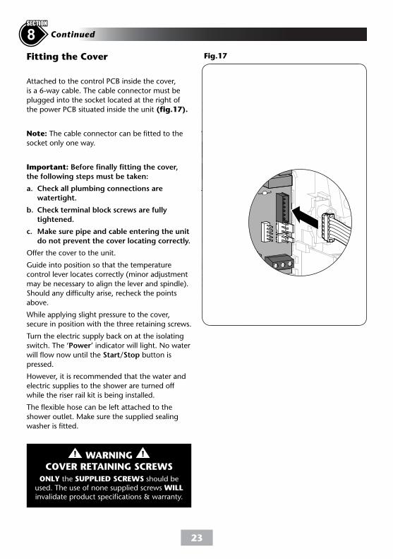
Attached to the control PCB inside the cover,
is a 6-way cable. The cable connector must be
plugged into the socket located at the right of
the power PCB situated inside the unit (fig.17).
Note: The cable connector can be fitted to the
socket only one way.
Important: Before finally fitting the cover,
the following steps must be taken:
a. Check all plumbing connections are
watertight.
b. Check terminal block screws are fully
tightened.
c. Make sure pipe and cable entering the unit
do not prevent the cover locating correctly.
Offer the cover to the unit.
Guide into position so that the temperature
control lever locates correctly (minor adjustment
may be necessary to align the lever and spindle).
Should any difficulty arise, recheck the points
above.
While applying slight pressure to the cover,
secure in position with the three retaining screws.
Turn the electric supply back on at the isolating
switch. The ‘Power’ indicator will light. No water
will flow now until the Start/Stop button is
pressed.
However, it is recommended that the water and
electric supplies to the shower are turned off
while the riser rail kit is being installed.
The flexible hose can be left attached to the
shower outlet. Make sure the supplied sealing
washer is fitted.
Fig.17Fitting the Cover
WARNINGCOVER RETAINING SCREWS
ONLY the SUPPLIED SCREWS should be used. The use of none supplied screws WILL invalidate product specifications & warranty.
24
8Continued
SECTION
Fig.18
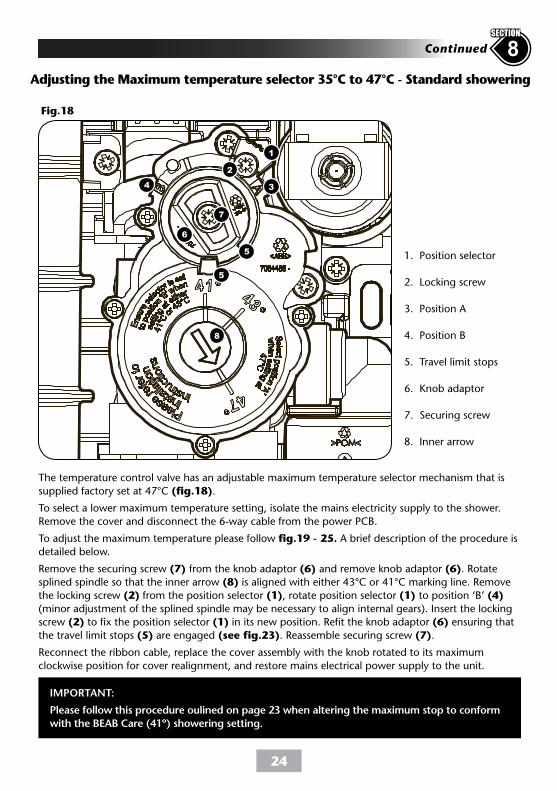
The temperature control valve has an adjustable maximum temperature selector mechanism that is
supplied factory set at 47°C (fig.18).
To select a lower maximum temperature setting, isolate the mains electricity supply to the shower.
Remove the cover and disconnect the 6-way cable from the power PCB.
To adjust the maximum temperature please follow fig.19 - 25. A brief description of the procedure is
detailed below.
Remove the securing screw (7) from the knob adaptor (6) and remove knob adaptor (6). Rotate
splined spindle so that the inner arrow (8) is aligned with either 43°C or 41°C marking line. Remove
the locking screw (2) from the position selector (1), rotate position selector (1) to position ‘B’ (4)
(minor adjustment of the splined spindle may be necessary to align internal gears). Insert the locking
screw (2) to fix the position selector (1) in its new position. Refit the knob adaptor (6) ensuring that
the travel limit stops (5) are engaged (see fig.23). Reassemble securing screw (7).
Reconnect the ribbon cable, replace the cover assembly with the knob rotated to its maximum
clockwise position for cover realignment, and restore mains electrical power supply to the unit.
Adjusting the Maximum temperature selector 35°C to 47°C - Standard showering
1
2
34
5
5
8
6
7
1. Position selector
2. Locking screw
3. Position A
4. Position B
5. Travel limit stops
6. Knob adaptor
7. Securing screw
8. Inner arrow
IMPORTANT:
Please follow this procedure oulined on page 23 when altering the maximum stop to conform
with the BEAB Care (41º) showering setting.
25
8 Continued
SECTION
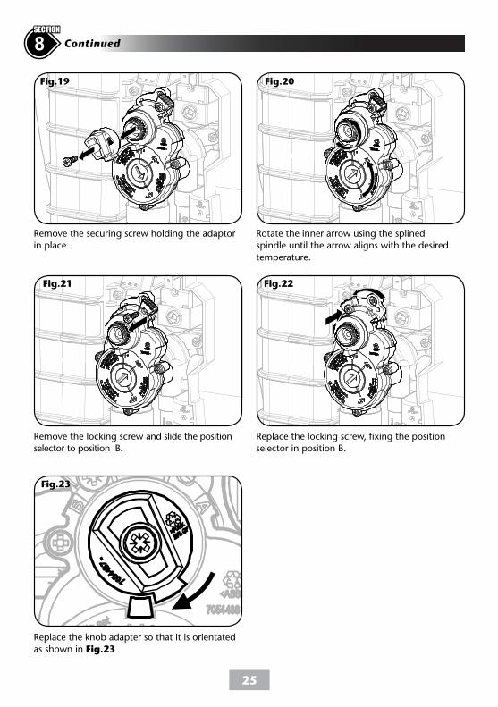
Replace the knob adapter so that it is orientated
as shown in Fig.23
Fig.23
Replace the locking screw, fixing the position
selector in position B.
Remove the locking screw and slide the position
selector to position B.
Fig.21 Fig.22
Fig.19 Fig.20
Remove the securing screw holding the adaptor
in place.
Rotate the inner arrow using the splined
spindle until the arrow aligns with the desired
temperature.
26
8Continued
SECTION
Fig.26
Fig.27
Fig.25
Fig.24
BEAB Care
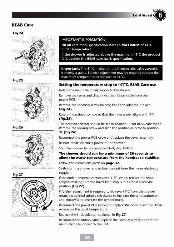
IMPORTANT INFORMATION:
*BEAB care mark specification states a MAXIMUM of 41°C
outlet temperature.
If the shower is adjusted above the maximum 41°C the product
falls outside the BEAB care mark specification.
Setting the temperature stop to *41ºC, BEAB Care use
Isolate the mains electricity supply to the shower.
Remove the cover and disconnect the ribbon cable from the
power PCB.
Remove the securing screw holding the knob adaptor in place
(fig.24).
Rotate the splined spindle so that the inner arrow aligns with 41º
(fig.25).
The position selector should be set to position ‘B’ for BEAB care mode.
Remove the locking screw and slide the position selector to position
‘B’ (fig.26).
Reconnect the power PCB cable and replace the cover assembly.
Restore mains electrical power to the shower.
Start the shower by pressing the Start/Stop button.
The shower should run for a minimum of 30 seconds to
allow the water temperature from the handset to stabilise.
Follow the instructions given on page 32.
Switch off the shower and isolate the unit from the mains electricity
supply.
If the outlet temperature measured 41ºC simply replace the knob
adaptor making sure the travel limit stop is in its most clockwise
position (fig.27).
If further adjustment is required to achieve 41ºC from the shower
rotate the splined spindle (clockwise to increase the temperature or
anti-clockwise to decrease the temperature).
Reconnect the power PCB cable and replace the cover assembly. Then
remeasure the oulet temperature.
Replace the knob adaptor as shown in fig.27.
Reconnect the ribbon cable, replace the cover assembly and restore
mains electrical power to the unit.
Important: The 41°C marker on the thermostatic valve assembly
is merely a guide. Further adjustment may be required to tune the
maximum temperature of the unit to 41°C.
27
Dip Switch No. Operation Enabled Switch Position
ON
ON
ON
ON
ON
1 2 3 4 5
ON
ON
ON
ON
ON
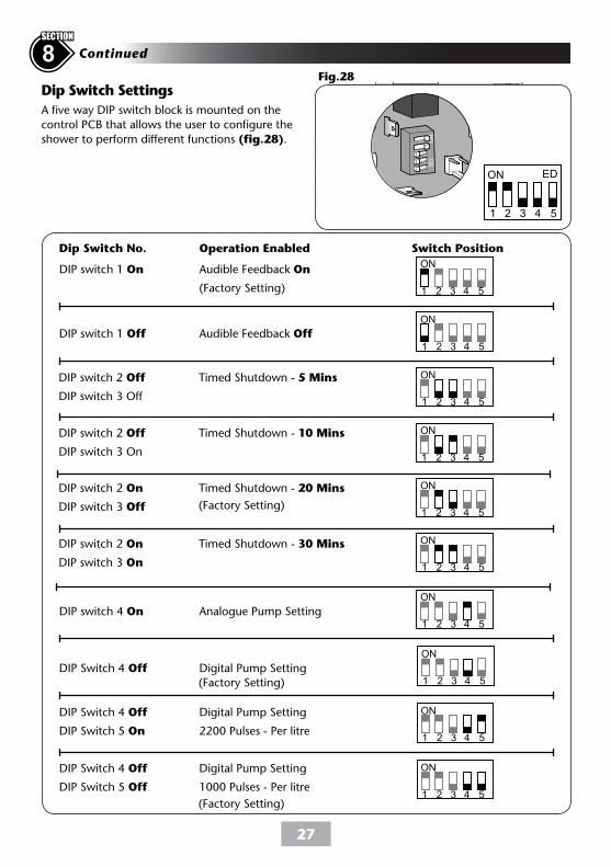
Dip Switch Settings
A five way DIP switch block is mounted on the
control PCB that allows the user to configure the
shower to perform different functions (fig.28).
DIP Switch 4 Off Digital Pump Setting
DIP Switch 5 Off 1000 Pulses - Per litre
DIP Switch 4 Off Digital Pump Setting
DIP Switch 5 On 2200 Pulses - Per litre
DIP Switch 4 Off Digital Pump Setting
DIP switch 4 On Analogue Pump Setting
DIP switch 2 On Timed Shutdown - 30 Mins
DIP switch 3 On
DIP switch 2 On Timed Shutdown - 20 Mins
DIP switch 3 Off
DIP switch 2 Off Timed Shutdown - 10 Mins
DIP switch 3 On
DIP switch 2 Off Timed Shutdown - 5 Mins
DIP switch 3 Off
DIP switch 1 Off Audible Feedback Off
ON ED
1 2 3 4 5
DIP switch 1 On Audible Feedback On
(Factory Setting)
(Factory Setting)
(Factory Setting)
(Factory Setting)
8 Continued
SECTION
Fig.28
1 2 3 4 5
1 2 3 4 5
1 2 3 4 5
1 2 3 4 5
1 2 3 4 5
1 2 3 4 5
1 2 3 4 5
1 2 3 4 5
1 2 3 4 5
28
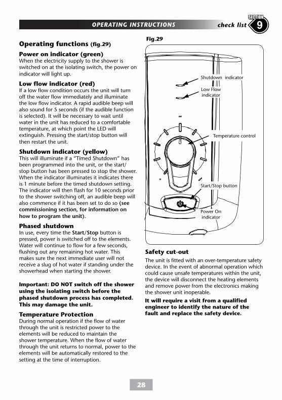
Fig.29
Start/Stop button
Power Onindicator
Shutdown indicator
Temperature control
Low Flow indicator
Operating functions (fig.29)
Power on indicator (green)When the electricity supply to the shower is switched on at the isolating switch, the power on
indicator will light up.
Low flow indicator (red)If a low flow condition occurs the unit will turn off the water flow immediately and illuminate the low flow indicator. A rapid audible beep will also sound for 5 seconds (if the audible function is selected). It will be necessary to wait until water in the unit has reduced to a comfortable temperature, at which point the LED will extinguish. Pressing the start/stop button will
then restart the unit.
Shutdown indicator (yellow)This will illuminate if a “Timed Shutdown” has been programmed into the unit, or the start/stop button has been pressed to stop the shower. When the indicator illuminates it indicates there is 1 minute before the timed shutdown setting. The indicator will then flash for 10 seconds prior to the shower switching off, an audible beep will also commence if it has been set to do so (see commissioning section, for information on
how to program the unit).
Phased shutdownIn use, every time the Start/Stop button is pressed, power is switched off to the elements. Water will continue to flow for a few seconds, flushing out any remaining hot water. This makes sure the next immediate user will not receive a slug of hot water if standing under the showerhead when starting the shower.
Important: DO NOT switch off the shower
using the isolating switch before the
phased shutdown process has completed.
This may damage the unit.
Temperature ProtectionDuring normal operation if the flow of water through the unit is restricted power to the elements will be reduced to maintain the shower temperature. When the flow of water through the unit returns to normal, power to the elements will be automatically restored to the
setting at the time of interruption.
OPERATING INSTRUCTIONS 9check list
SECTION
Safety cut-out
The unit is fitted with an over-temperature safety device. In the event of abnormal operation which could cause unsafe temperatures within the unit, the device will disconnect the heating elements and remove power from the electronics making the shower unit inoperable.
It will require a visit from a qualified engineer to identify the nature of the fault and replace the safety device.
29
Instructions for installers and service engineers onlyINSTRUCTIONS FOR INSTALLERS AND SERVICE ENGINEERS ONLYInstructions for installers and service engineers only
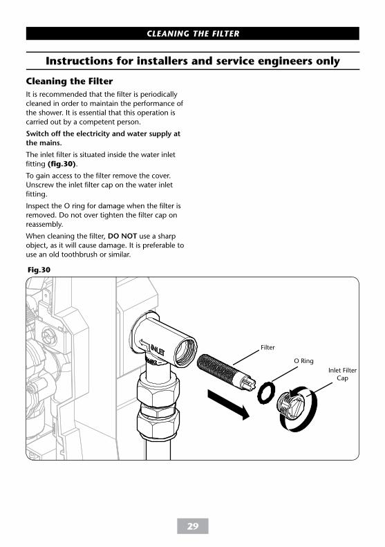
Fig.30
It is recommended that the filter is periodically
cleaned in order to maintain the performance of
the shower. It is essential that this operation is
carried out by a competent person.
Switch off the electricity and water supply at
the mains.
The inlet filter is situated inside the water inlet
fitting (fig.30).
To gain access to the filter remove the cover.
Unscrew the inlet filter cap on the water inlet
fitting.
Inspect the O ring for damage when the filter is
removed. Do not over tighten the filter cap on
reassembly.
When cleaning the filter, DO NOT use a sharp
object, as it will cause damage. It is preferable to
use an old toothbrush or similar.
Filter
O Ring
Cleaning the Filter
Inlet FilterCap
CLEANING THE FILTER
30
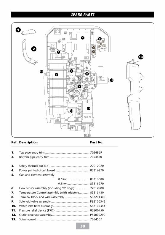
Ref. Description Part No.
1. Top pipe entry trim .................................................... 7054869
2. Bottom pipe entry trim .............................................. 7054870
3. Safety thermal cut-out ................................................ 22012020
4. Power printed circuit board ........................................ 83316270
5. Can and element assembly
8.5Kw .......................... 83313080
9.5Kw .......................... 83315270
6. Flow sensor assembly (including ‘O’ rings) ................. 22012980
7. Temperature Control assembly (with adapter) ............ 83315430
8. Terminal block and wires assembly ............................. S82201300
9. Solenoid valve assembly ............................................. P82100345
10. Water inlet filter assembly ........................................... S82100344
11. Pressure relief device (PRD) ......................................... 82800450
12. Outlet reservoir assembly............................................ P85000290
13. Splash guard .............................................................. 7054507
3
1
2
4
5
6
7
8
9
11
12
10
13
14
SPARE PARTS
31
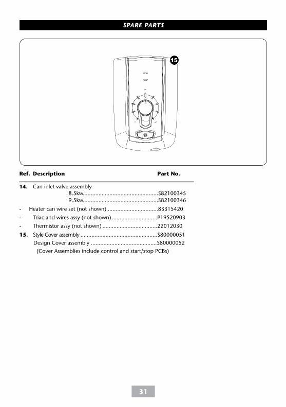
Ref. Description Part No.
14. Can inlet valve assembly
8.5kw................................................S82100345
9.5kw................................................S82100346
- Heater can wire set (not shown).................................83315420
- Triac and wires assy (not shown) .............................P19520903
- Thermistor assy (not shown) ...................................22012030
15. Style Cover assembly .................................................S80000051
Design Cover assembly ..........................................S80000052
(Cover Assemblies include control and start/stop PCBs)
15
SPARE PARTS

32
FAULT FINDINGImportant: Switch off the electricity at the mains supply and remove the circuit fuse before
attempting any fault finding inside the unit.
1 Shower inoperable, no
water flow.
2 Water too hot.
3 Water too cool or cold.
4 Water will not stop
flowing from unit
unless switched off at
isolating switch.
1.1 Interrupted power
supply.
1.2 Unit malfunction.
1.3 Thermal cut-out
operated.
1.4 PCB - NTC has
operated.
2.1 Temperature control
set incorrectly.
2.2 Unit malfunction.
3.1 Temperature control
set incorrectly.
3.2 Maximum
temperature selector
set incorrectly.
3.3 Unit malfunction.
4.1 Control cable is not
connected to PCB.
1.1.1 Blown fuse or circuit breaker. Check supply
Renew or reset fuse or circuit breaker. If it fails
again, consult a qualified electrician.
1.2.1 Power cut? Check other appliances and if
necessary, contact local Electricity Supply Co.
1.2.2 Have unit checked. Ring Customer Service.
1.3.1 The thermal cut-out safety device has operated.
Have the unit checked by a suitably qualified
service engineer or contact Customer Service.
1.4.1 The PCB has an NTC safety device which has
operated. Have the unit checked by a suitably
qualified service engineer or contact Customer
Service.(lights and audio still in operation)
2.1.1 Alter the temperature control.
2.2.1 Have the unit checked by a suitably qualified
service engineer or contact Customer Service.
3.1.1 Alter the temperature control.
3.2.1 Alter the Maximum temperature selector.
3.3.1 Have the unit checked by a suitably qualified
service engineer or contact Customer Service.
4.1.1 Remove cover and connect cable.
Problem/Symptom Cause Action/Cure
FAULT FINDING/TROUBLESHOOTING

33
6.1.1 Insufficient water flow available.
1. Check showerhead is not blocked
2. Check shower hose is not restricted.
3. Check filter is not blocked.
4. Check water supply to shower is adequate
7.1.1 Shower will not start until water in the unit has
cooled and LED goes off. If problem persists.
1. Check showerhead is not blocked
2. Check shower hose is not restricted.
3. Check filter is not blocked.
4. Check water supply to shower is adequate
8.1.1 Replace flow sensor assembly
9.1.1 Replace cover assembly
10.1.1 Replace thermistor
6.1 Low flow condition
7.1 Low flow condition
has caused
temperature sensor
in the shower to
operate.
8.1 Flow sensor has
failed
9.1 Start/Stop PCB
failed
10.1 Outlet thermistor
failed
5 Pressure relief device
has operated (water
ejected from PRD
tube).
5.1 Blocked showerhead.
5.2 Twisted/blocked
flexible shower hose.
5.3 Showerhead not
removed while
commissioning.
5.1.1 Clean sprayplate and then fit a new PRD.
5.2.1 Check for free passage through hose. Replace
hose if necessary and then fit new PRD.
5.3.1 Fit new PRD. Commission unit with
showerhead removed.
Problem/Symptom Cause Action/Cure
6 Low flow LED
permanently on when
start/stop bar pressed.
Shower will not start.
7 Low flow LED comes
on when shower is
running. Shower
switches off.
8 Low flow LED flashes
continuously when
start/stop bar pressed.
Shower will not start.
9 Low flow and shutdown
LED’s alternately
flashing when power
turned on to unit.
Shower will not start.
10 Low flow and
shutdown
LED’S flashing
simultaneously when
start/stop bar pressed.
Shower will not start.
34
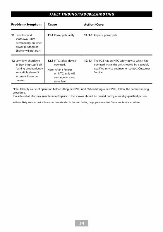
11 Low flow and
shutdown LED’S
permanently on when
power is turned on.
Shower will not start.
12 Low flow, shutdown
& Start Stop LED’S all
flashing simultaniously
an audible alarm (If
in use) will also be
present.
.
11.1 Power pcb faulty
12.1 NTC saftey device
operated.
Note: After 3 failures
on NTC, unit will
continue to show
same fault.
11.1.1 Replace power pcb
12.1.1 The PCB has an NTC safety device which has
operated. Have the unit checked by a suitably
qualified service engineer or contact Customer
Service.
Problem/Symptom Cause Action/Cure
Note: Identify cause of operation before fitting new PRD unit. When fitting a new PRD, follow the commissioning
procedure.
It is advised all electrical maintenance/repairs to the shower should be carried out by a suitably qualified person.
In the unlikely event of unit failure other than detailed in the fault finding page, please contact Customer Service for advice.
FAULT FINDING/TROUBLESHOOTING
35
OMNICARE
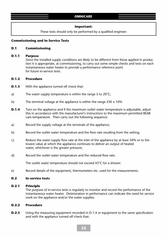
Commissioning and In-Service Tests
D.1 Commissioning
D.1.1 Purpose Since the installed supply conditions are likely to be different from those applied in produc tion it is appropriate, at commissioning, to carry out some simple checks and tests on each instantaneous water heater to provide a performance reference point for future in-service tests. D.1.2 Procedure
D.1.3 With the appliance turned off check that:
a) The water supply temperature is within the range 5 to 20°C;
b) The terminal voltage at the appliance is within the range 230 ± 10%
D.1.4 Turn on the appliance and if the maximum outlet water temperature is adjustable, adjust this in accordance with the manufacturer’s instructions to the maximum permitted BEAB care temperature. Then carry out the following sequence:
a) Record the supply voltage at the terminals of the appliance;
b) Record the outlet water temperature and the flow rate resulting from the setting;
c) Reduce the water supply flow rate at the inlet of the appliance by at least 50% or to the lowest value at which the appliance continues to deliver an output of heated water, whichever is the greater pressure;
d) Record the outlet water temperature and the reduced flow rate.
The outlet water temperature should not exceed 43°C for a shower.
e) Record details of the equipment, thermometers etc. used for the measurements.
D.2 In-service tests
D.2.1 Principle The purpose of in-service tests is regularly to monitor and record the performance of the instantaneous water heater. Deterioration in performance can indicate the need for service work on the appliance and/or the water supplies.
D.2.2 Procedure
D.2.3 Using the measuring equipment recorded in D.1.4 or equipment to the same specification and with the appliance turned off check that:
Important:
These tests should only be performed by a qualified engineer.
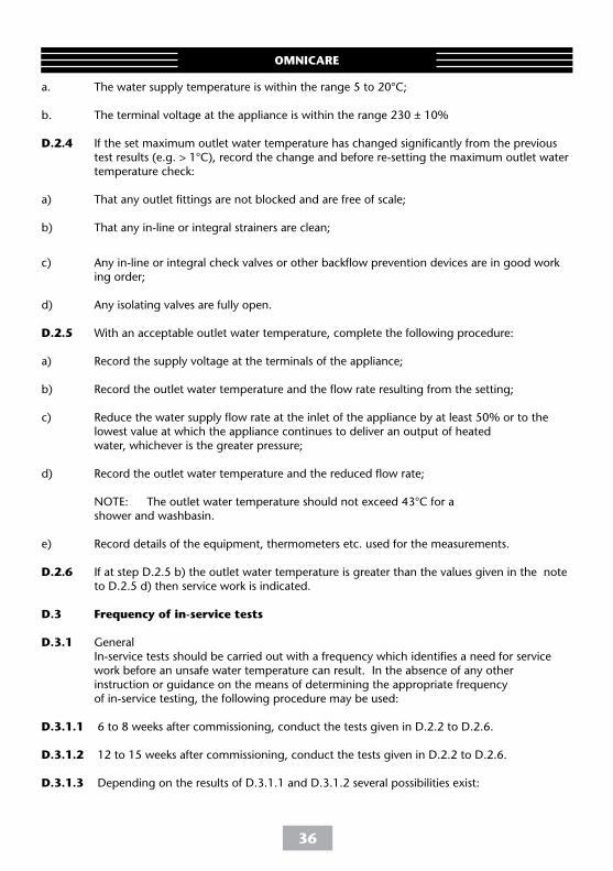
OMNICARE
a. The water supply temperature is within the range 5 to 20°C;
b. The terminal voltage at the appliance is within the range 230 ± 10%
D.2.4 If the set maximum outlet water temperature has changed significantly from the previous test results (e.g. > 1°C), record the change and before re-setting the maximum outlet water temperature check:
a) That any outlet fittings are not blocked and are free of scale;
b) That any in-line or integral strainers are clean;
c) Any in-line or integral check valves or other backflow prevention devices are in good work ing order;
d) Any isolating valves are fully open.
D.2.5 With an acceptable outlet water temperature, complete the following procedure:
a) Record the supply voltage at the terminals of the appliance;
b) Record the outlet water temperature and the flow rate resulting from the setting;
c) Reduce the water supply flow rate at the inlet of the appliance by at least 50% or to the lowest value at which the appliance continues to deliver an output of heated water, whichever is the greater pressure;
d) Record the outlet water temperature and the reduced flow rate;
NOTE: The outlet water temperature should not exceed 43°C for a shower and washbasin.
e) Record details of the equipment, thermometers etc. used for the measurements.
D.2.6 If at step D.2.5 b) the outlet water temperature is greater than the values given in the note to D.2.5 d) then service work is indicated.
D.3 Frequency of in-service tests
D.3.1 General In-service tests should be carried out with a frequency which identifies a need for service work before an unsafe water temperature can result. In the absence of any other instruction or guidance on the means of determining the appropriate frequency of in-service testing, the following procedure may be used:
D.3.1.1 6 to 8 weeks after commissioning, conduct the tests given in D.2.2 to D.2.6.
D.3.1.2 12 to 15 weeks after commissioning, conduct the tests given in D.2.2 to D.2.6.
D.3.1.3 Depending on the results of D.3.1.1 and D.3.1.2 several possibilities exist:
36
37
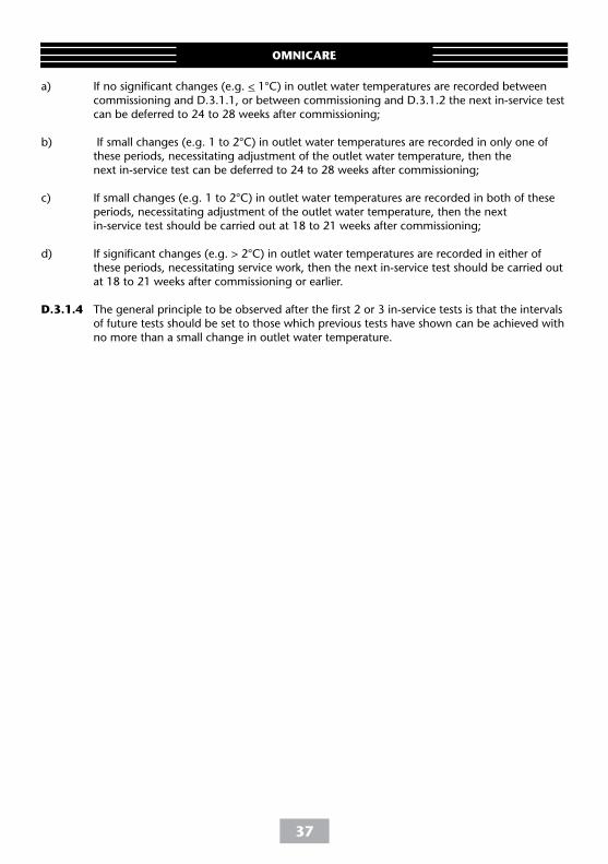
a) If no significant changes (e.g. < 1°C) in outlet water temperatures are recorded between commissioning and D.3.1.1, or between commissioning and D.3.1.2 the next in-service test can be deferred to 24 to 28 weeks after commissioning; b) If small changes (e.g. 1 to 2°C) in outlet water temperatures are recorded in only one of these periods, necessitating adjustment of the outlet water temperature, then the next in-service test can be deferred to 24 to 28 weeks after commissioning;
c) If small changes (e.g. 1 to 2°C) in outlet water temperatures are recorded in both of these periods, necessitating adjustment of the outlet water temperature, then the next in-service test should be carried out at 18 to 21 weeks after commissioning;
d) If significant changes (e.g. > 2°C) in outlet water temperatures are recorded in either of these periods, necessitating service work, then the next in-service test should be carried out at 18 to 21 weeks after commissioning or earlier. D.3.1.4 The general principle to be observed after the first 2 or 3 in-service tests is that the intervals of future tests should be set to those which previous tests have shown can be achieved with no more than a small change in outlet water temperature.
OMNICARE
38
OMNICARE
WEEE Directive – Policy Statement
As a producer and a supplier of electric showers, Triton Showers is committed to the protection of the environment via our own environmental policy and the compliance with the WEEE directive.
Triton Showers is fully registered with the Environment Agency under the following schemes:
Repic: Producers take-back scheme (PTS), registration number WEE/EJ3466QV
Valpak: Distributor take-back scheme (DTS), registration number 9659
All our electric products are labelled accordingly with the crossed out wheeled bin symbol. This indicates, for disposal purposes at end of life, that these products must be taken to a recognised collection points, such as local authority sites/local recycling centres; this will be free of any charges. Do not return to Triton Showers.

Triton Showers Triton Road Nuneaton Warwickshire CV11 4NR
Triton is a division of Norcros Group (Holdings) Limited
E-mail: [email protected]
Extended Warranty AVAILABLE NOW. Call 02476 378495 for more details.
TRITON STANDARD GUARANTEEWith the exception of accessories, Triton guarantee the product against all manufacturing defects for a period of
2 years (for domestic use only) from the date of purchase, provided that it has been installed by a competent person in full accordance with the fitting instructions.
All accessories such as shower heads, hoses and riser rails carry a 1 year parts only guarantee against manufacturing defects.
Any part found to be defective during this guarantee period we undertake to repair or replace at our option without charge so long as it has been properly maintained and operated in accordance with the operating instructions, and has not been subject to misuse or damage. This product must not be taken apart, modified or repaired except by a person authorised by Triton. This guarantee applies only to products installed within the United Kingdom and does not apply to products used commercially. This guarantee does not affect your statutory rights.
What is not covered:
22-09-15
UK SERVICE POLICYIn the event of a product fault or complaint occurring, the following procedure should be followed:
1. Telephone Customer Service on 024 7637 2222 having available, your details including post code, the model number and power rating of the product, together with the date of purchase and, where applicable, details of the particular fault.
2. If required, the Customer Service Advisor will arrange
for a qualified engineer to call.
3. All products attended to by a Triton service engineer must be installed in full accordance with the Triton installation guide applicable to the product. (Every product pack contains an installation guide, however, they can also be downloaded free atwww.tritonshowers.co.uk).
4. Our engineer will require local parking and if a permit is required this must be available to the engineer on arrival at the call.
5. It is essential that you or an appointed representative (who must be over 18 years of age) is present for the duration of the service engineer's visit. If the product is in guarantee you must produce proof of purchase.
6. Where a call under the terms of guarantee has been booked and the failure is not product related (i.e. scaling and furring, incorrect water pressure, pressure relief device operation or electrical/plumbing installation fault) a charge will be made. A charge will also be issued if nobody is at home when the service engineer calls or adequate parking/permit is not available.
7. If the product is no longer covered by the guarantee an up front fxed fee will be charged before the site visit.
8. Should proof of purchase not be available on an “in-guarantee” call, or should the service engineer find that the product is no longer under guarantee, the engineer will charge the same fixed price and the customer will be expected to pay the engineer before he leaves. If payment is not made on the day an administration charge will be added to the fixed charge.
9. If a debt is outstanding from a previous visit, or from any other Triton purchase, Triton reserves the right to withhold service until the debt has been settled.
10. Triton takes the health, safety and wellbeing of its employees very seriously and expects customers to treat all staff members with respect. Should any employee feel threatened or receive abuse, either verbally or physically, Triton reserves the right to withhold service
1. Breakdown due to: a) use other than domestic use by you or your resident family; b) wilful act or neglect;
c) any malfunction resulting from the incorrect use or quality of electricity, gas or water or incorrect setting of controls; d) failure to install in accordance with this installation guide
2. Claims for missing parts once the product has been installed.
3. Repair costs for damage caused by foreign objects or substances.
4. Total loss of the product due to non-availability of parts.
5. Compensation for loss of use of the product or consequential loss of any kind.
6. Call out charges where no fault has been found with the appliance.
7. The cost of repair or replacement of isolating switches, electrical cable, fuses and/or circuit breakers or any other accessories installed at the same time. Replacement of the Pressure Relief Device that only activates when the shower outlet is blocked, is also excluded.
8. The cost of routine maintenance, adjustments, overhaul modifications or loss or damage arising therefrom, including the cost of repairing damage, breakdown, malfunction caused by corrosion, furring,
9. Call out charges where the water supply cannot be isolated, this includes consequential losses arising from unserviceable supply valves.
www.tritonshowers.co.uk
Customer Service: 024 7637 2222
Trade Installer Hotline: 024 7637 8344 Fax: 024 7632 4504
www.tritonshowers.co.uk
Replacement parts policy1.1. It is the policy of Triton Showers to maintain parts availability for the duration of production and a period of 5 years thereafter in accordance with industry standards. Spare parts can be ordered via our online spare parts store, or by telephoning Triton Customer Service Spares Department on 024 7637 2222. Payment should be made by credit / debit card (excluding American Express or Diners Card). Payment can also be made by pre-payment of a pro-forma invoice, by cheque or postal order. 1.2. Telephone orders are based on information given during the call. Before contacting Triton, please verify your requirements using the information contained in the user guide. Triton cannot accept liability for incorrect part identification.