omega series 500 - aadkins.comaadkins.com/images/pdfs/manuals/omega_series500_old.pdf · preface...
TRANSCRIPT

Omega Series 500
©2015 a.adkins and sons limited. all rights reserved
Operators Handbook

Copyrights
©2013, A. Adkins & Sons Limited, High Cross, Lancaster Road, Hinckley, Leicestershire. No part of this publication may be reproduced by any means without the prior written permission of A. Adkins & Sons Limited. Omega Series 500 Press is a registered trademark of A. Adkins & Sons Limited.
Please read this manual carefully and keep it with your machine at all times for reference.

Preface Dear User Welcome to the growing group of Omega Series 500 Press users. The product you have purchased has been carefully designed and manufactured to ensure that you, the user, will gain the maximum benefit. All A. Adkins & Sons products are specifically designed to ensure ease of use with particular attention to safety requirements. Should you discover any fault or damage upon receipt of this product, you should immediately contact your supplier.
Contents 1. Introduction Omega Series 500 Press 1 1.1 What did you receive? 2 1.2 Specifications of the Omega Series 500 Press 3 1.3 Safety 4 1.4 Safety tips 4 2. Installation 6 2.1 Transport instructions 6 2.2 Installing the machine 6 2.3 Electrical requirements 6 2.4 Pneumatic requirements 7 2.5 Adjusting the pressure 7 3. How to operate the Omega Series 500
Press 8
3.1 Starting with the Omega Series 500 Press 8 3.2 Working with heat transfer materials 8 3.3 Pressing pad assembly 9 3.4 Shutting down the machine 9 3.5 Fault diagnosis 9 3.6 Hints and tips 10
4. Maintenance of the Machine 11 4.1 Daily maintenance 11 4.2 Periodic maintenance 11 4.3 Cleaning 11
5. Machine Drawings and Diagrams 12 5.1 General layout 13 5.2 Control unit operation 14 5.3 Exploded diagram and parts list 15 5.4 Machine - electrical diagram 16 5.5 Controller - electrical diagram 17 5.6 Pneumatic schematic 18 6. Design Change 19
7. Guarantee 20 Declaration of Conformity 21

Page 1
1. Introduction Omega Series 500 Press
The Omega Series 500 Press is a pneumatically operated heat press for transfer printing and material fusing. It is ideal for medium volume production with low operator fatigue. The work areas of the Omega Series 500 Press are 21 x 34 cm (8.25 x 13.3 in) but machines may have special order, optional smaller sized interchangeable worktables of any size and various shapes within these table sizes. The Omega Series 500 Press has a heat plate which swings away from the operating position to clear the worktable for loading and unloading. After loading the work piece, and with the correct settings for temperature, pressure and dwell time, the heat plate is swung to the operating position with the handles provided. The cycle is started by simultaneously pressing the two green buttons on the top of the handles within ½ second. The controller operates the timer and the solenoid valve and thus the pneumatic cylinder. When the set time elapses the Heat Plate is automatically lifted, enabling the head to be swung away. The worktable may then be unloaded and reloaded ready for another cycle. The Omega Series 500 Press is produced in two versions, nominally 230-240 Volts AC for the European market and nominally 110 Volts for the American market. It is a simple operation to remove the worktable and replace it with one of a different size.

Page 2
1.1 What did you receive? The Omega Series 500 Press has been placed in a crate, and then held in place with a wooden jig and protected by a polystyrene liner finally it is banded onto a pallet, for safe transportation. The following articles should have been delivered: Omega Series 500 Press complete with mains cable and plug Omega Series 500 Press Operators Handbook Any extra items ordered If there is any damage or any article is missing, please contact your supplier immediately.

Page 3
1.2 Specifications of the Omega Series 500 Press The Omega Series 500 Press is a pneumatically operated heat press for transfer printing and material fusing. It is ideal for medium volume production with low operator fatigue. The work area of the Omega Series 500 Press is 21 x 34 cm (8.25 x 13.3 in) but machines may have, to special order, optional smaller sized interchangeable worktables of any size and various shapes within this table size. Specification
European Machine
Power consumption 1500 WattsPower supply 230 Volts ACCompressed air supply 7 bar maxWorking temperature 70-235oCDisplay Timer Range 0 – 9.59 minMachine height open 49 cmMachine width 85 cmMachine depth 61 cmWeight export packed 71 kgSize export packed 94(L) x 65(W) x 65 cm (H)Net weight 45 KgPress pad dimensions (x2) 21 x 24 cmFuses 8A Specification USA Machine
Power consumption 1600 WattsPower supply 110 Volts ACCompressed air supply 100 psi maxWorking temperature 160-455oFDisplay Timer Range 0 – 9.59 minMachine height open 19.3 inMachine width 33.5 inMachine depth 24 inWeight export packed 156.5 lbs.Size export packed 37(L) x 25.5(W) x 25.5 in (H) Net weight 99.2 lbs.Press pad dimensions (x2) 8.25 x 13.3 inFuses 16A

Page 4
1.3 Safety The Omega Series 500 Press has been equipped with various safety features to ensure operator safety. a. A thermal cut-out on the heating element shuts off the power
to the element if the temperature exceeds 235oC ± 15oC (455oF ± 27oF).
b. The time/temperature controller has a built in facility giving
error messages in the event of faults with the element heating and control system.
c. A two button starting system ensures that the operator’s hands
are well away from the heat plate when the table rises. d. Emergency stop button. e. The machine table will only set to pressing position when the
heat plate is aligned with it due to a micro switch safety interlock
1.4 Safety Tips If required, our customer service team can arrange maintenance service. The Omega Series 500 Press meets the European Legislation
standard. Under normal conditions accidents are rare. However listed below are some practical points to ensure your safety.
Always switch off and isolate the mains supply (i.e.
Remove plug) before undertaking any maintenance work or cleaning the machine.
Keep other people away from the machine during use.
Ensure that there is sufficient space around the machine. Cables and connections must not get jammed. Although the heat radiation of the press is low, there should be enough space for cooling down.
Avoid contact with the press element. DO NOT REMOVE THE TOP COVER UNLESS
QUALIFIED TO DO SO - touching internal parts is dangerous and may cause shock hazard.
PROTECT THE MAINS CABLE - damage to the mains
cable may cause fire or shock hazard. When unplugging, hold by the plug only and remove carefully. Take care that the mains cable does not come into contact with the heat plate (or

Page 5
Safety Tips (cont.)
moving parts of the mechanism) during operation of the machine.
OPERATING AMBIENT TEMPERATURE RANGE - the
operating ambient temperature range is 32oF - 104oF, (0oC - 35oC) and humidity of 20 - 80%. This heat press is fitted with a thermal cut out to ensure that it cannot operate above 235oC 15oC (455oF 27oF).
MACHINE FUSES - type: 2-8 amp x 20 mm long fuse
incorporated into mains socket unit. WARNING - THIS APPARATUS MUST BE EARTHED
(GROUNDED) CAUTION
This machine gets hot whilst operating. Take care not to touch any surfaces that are labelled “Caution this plate is HOT”.
MACHINE OPERATION
Only suitably trained personnel should operate this machine. This machine is designed to be operated by one operator only. If air pressure is lost the machine will operate normally until the air reservoir is empty. Contact your print media suppliers to ascertain whether fumes are given off during the process, and if so what precautions are needed for operator safety. These may include air extraction and/or masks for personnel.
Please refer to page 13 for an illustration of the Omega Series 500 Press.
Page 6
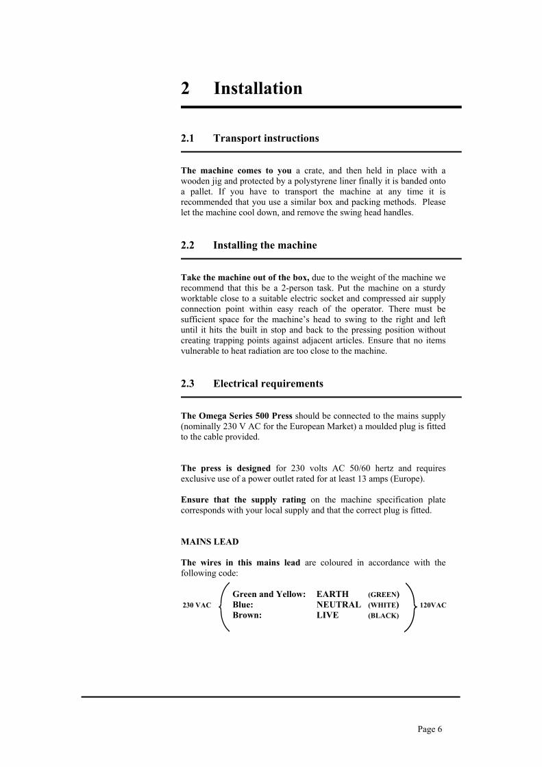
2 Installation
2.1 Transport instructions The machine comes to you a crate, and then held in place with a wooden jig and protected by a polystyrene liner finally it is banded onto a pallet. If you have to transport the machine at any time it is recommended that you use a similar box and packing methods. Please let the machine cool down, and remove the swing head handles. 2.2 Installing the machine Take the machine out of the box, due to the weight of the machine we recommend that this be a 2-person task. Put the machine on a sturdy worktable close to a suitable electric socket and compressed air supply connection point within easy reach of the operator. There must be sufficient space for the machine’s head to swing to the right and left until it hits the built in stop and back to the pressing position without creating trapping points against adjacent articles. Ensure that no items vulnerable to heat radiation are too close to the machine. 2.3 Electrical requirements The Omega Series 500 Press should be connected to the mains supply (nominally 230 V AC for the European Market) a moulded plug is fitted to the cable provided. The press is designed for 230 volts AC 50/60 hertz and requires exclusive use of a power outlet rated for at least 13 amps (Europe). Ensure that the supply rating on the machine specification plate corresponds with your local supply and that the correct plug is fitted. MAINS LEAD The wires in this mains lead are coloured in accordance with the following code: Green and Yellow: EARTH (GREEN) 230 VAC Blue: NEUTRAL (WHITE) 120VAC
Brown: LIVE (BLACK)

Page 7
2.3A Wiring the plug For a 230 VAC machine
As the colours of the wires in the mains lead of this apparatus may not correspond with the coloured markings identifying the terminals in your plug, proceed as follows:- 1. The wire, which is, coloured green and yellow must be
connected to the terminal in the plug, which is marked by the letter E, or by the safety earth symbol coloured green, or green and yellow.
2. The wire coloured blue must be connected to the terminal,
which is marked with the letter N, (Neutral connector). 3. The wire coloured brown must be connected to the terminal,
which is marked with the letter L, (Live connector). NOTE: Replacement of the mains cable must be done by a competent service engineer. 2.4 Pneumatic requirements The Omega Series 500 Press should be connected through a filter regulator to a compressed air supply capable of delivering 60 litres/min at a pressure of 3.5 - 7 bar max. (2 cu.ft/min at 50-100 psi). The press will not operate if the pressure drops below 3.5 bar. (40 psi.) Double hose clips should be used on the delivery hose. We would advise that when setting up the machine you check that sufficient pressure is maintained into the rear regulator valve. When the desired pressure is achieved the regulator is locked by pushing the knob back down. We recommend that this should be set between 4 to 6 Bar. The Pressure Adjustment Gauge on the front of the machine should only be used to control the settings required for heat transfer and garments. 2.5 Adjusting the pressure This press is fitted with a manually adjustable pneumatic pressure regulator on the base of the machine. To adjust the operating air pressure, and therefore the pressure exerted by the press on the work, the regulator is unlocked by pulling forward the black plastic knob. Turning the regulator knob clockwise will increase the air pressure; turning anticlockwise will decrease the pressure. When the desired pressure is achieved the regulator is locked by pushing the knob back in.

Page 8
3. How to Operate the Omega Series 500 Press
3.1 Starting with the Omega Series 500 Press 3.1.1 Turn on the Omega Series 500 Press; the on/off switch is
on the Right Hand side of the Base Unit. Set the machine controls as necessary. See instructions for adjusting the pressure, 2.5, and the operation of the time temperature unit, page 14. When the set temperature is steady in the display the machine is ready to use.
3.2 Working with Heat Transfer Materials 3.2.1 Ascertain from the supplier of the transfer paper and/or the
suppliers of the material, that the material to be used is suitable and has been prepared for transfer printing.
3.2.2 Obtain from the supplier of the transfer paper, or material to
be used, the recommended temperature, time and pressure settings for the material to be worked on.
Approximate settings are usually within the following:- 180oC - 200oC (350oF - 400oF) Heat Setting 10 - 30 seconds Time Dwell Setting
3.2.3 Wait until the set temperature has been reached, signalled by
the temperature on the controller display becoming steady at the desired figure. Swing the heat plate assembly to the right, or left using the handles on the both sides of the machine. Place the work piece on the pressure pad, removing all wrinkles. Place the transfer in the desired position. Swing the heat plate into the pressing position, to the stop, to ‘make’ the micro switch will enable the machine to cycle.
3.2.4 Start the sequence by pressing the two green buttons
simultaneously (within 0.5 seconds). The heat plate automatically drops to the table. (The process can be stopped at any time by using the “MODE” button on the front of the Controller. This will automatically lift the heat plate).
3.2.5 At the end of the set time, the heat plate lifts to the loading
position, allowing the head to be swung aside to permit unloading.

Page 9
3.3 Pressing Pad Assembly The pressing pads supplied with this machine are silicone rubber. The pressing pads must be maintained in good condition at all times and replaced when showing signs of wear. A worn pressing pad will always affect the quality of printing/fusing. Do not insert items into the machine, which would tend to cut the pressing pad, i.e. buttons, pins, press-studs or zips. IMPORTANT NOTE: The pressing pad supplied with the machine is of the correct thickness. Using a thicker pad may invalidate your warranty. 3.4 Shutting Down To shut down the machine when a cycle is finished, turn off the green illuminated rocker switch on the right hand side of the Machine Base. To temporarily interrupt the cycle, press the mode release button once. To shut down in an emergency, press the red button on the top of the machine head. If the emergency stop button is actuated, it will need to be unlocked by turning it clockwise before the machine will run again. 3.5 Fault Diagnosis This Omega Series 500 Press has built in fault diagnosis. The display may show the following: 1. Heat Fault If the element of the heat press, or the thermal cut-out go open
circuit, after approximately 20 minutes the display will show “Heat Fault”. If this display is seen, contact your machine supplier immediately.
2. Probe Fault If the probe goes open circuit, the display will show “Probe
Fault” immediately. Contact your machine supplier immediately.
3. “CAL” Fault If “CAL” appears in the controller display the controller will
need to be recalibrated. Switch off the machine and contact your supplier for an instruction sheet.

Page 10
Fault Diagnosis (cont.)
CAUTION
In all fault conditions switch off the power to the machine and unplug the machine from the electrical supply before contacting your machine supplier.
3.6 Hints and Tips Transfer Printing Extra care should always be taken to ensure that transfer paper is placed print down onto the article, as mistakes will result in the heat plate becoming soiled with ink and spoiling following work. When transfer printing, it may be found advantageous to cover the press pad with paper or P.T.F.E. to prevent strike-through of surplus ink, particularly when printing thin material as surplus print on the pressing pad cover can also strike back on the following work. Transfer Paper/Motifs Fail to Print Out Correctly Check:- 1. Heat and time dwell settings are correct. 2. Article having transfer applied is locked in contact between
pressing pad and heat plate. 3. Pressing pad is in good condition, is flat and making complete
contact over the whole area of the heat plate. See Pressing Pad details.
“Ghosting” (Double Image) of Transfer Prints Check:- 1. Material being used has been correctly heat set for transfer
printing. 2. Material being used does not shrink during printing process,
i.e. measure material before and after printing. 3. Transfer paper does not move after printing process upon lift
off of the heat plate. 4. If possible, use adhesive coated paper, particularly to
overcome fabric shrinkage. 5. By pre-shrinking of material in press before transfer printing.

Page 11
4. Maintenance of the Machine 4.1 Daily Maintenance For good press results it is important to keep the press surfaces clean. Wipe the surface of the heat plate with a dry non-abrasive cloth before use when the plate is cold. When heat plates are hot and not in use, keep in the open position away from the silicone pad. 4.2 Periodic Maintenance Periodically clean the Teflon coated heat platen with a non-abrasive piece of cloth. Stubborn stains may be cleaned, when platen is cool, with mineral spirits. 4.3 Cleaning First unplug the machine. Clean the outside of the machine frequently with a clean, moist cloth. This may conveniently be carried out when the machine is cold. To prevent soiling of substrate, periodic wiping of entire exterior machine, including platens, with a clean rag is recommended. If necessary, use mineral spirits for cleaning a cold machine. Since mineral spirits are flammable, use precautions at all times and keep away from sparks, flames or hot heat platen.

Page 12
5. Machine Drawings and Diagrams
On the following pages are the schematic diagrams for the Omega Series 500 Press. 5.1 General Layout…………………………….. Page 13 5.2 Control Unit – Operation…………………. Page 14 5.3 Exploded Diagram and Parts List………... Page 15 5.4 Machine - Electrical Diagram…………….. Page 16 5.5 Controller - Electrical Diagram…………... Page 17 5.6 Pneumatic Schematic……………………… Page 18
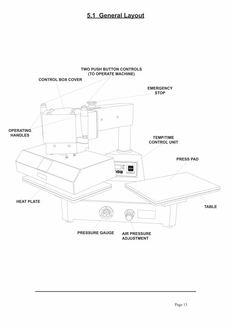
5.1 General Layout
OPERATINGHANDLES TEMP/TIME
CONTROL UNIT
AIR PRESSUREADJUSTMENT
PRESSURE GAUGE
TABLEHEAT PLATE
PRESS PAD
EMERGENCYSTOP
CONTROL BOX COVER
Page 13
TWO PUSH BUTTON CONTROLS(TO OPERATE MACHINE)

Page 14
ACTACT TEMPTEMP
SETSET
TIMETIME
Setting Temperature
Setting Time
5.2 Operation Of Control Unit, Setting Time and Temperature(The head must always be in the up position before the controller is set)
ACTACT TEMPTEMP
SETSET
TIMETIME
1.
2.
3.4.
5.
6.
Switch on Press; Display and 'TEMP' indicator will light up.Press 'MODE' button to select 'Set' on indicator. The Display will start flashing.Use the 'UP' and 'DOWN' arrow buttons to set the required temperature.When you have set the required temperature the Display will stop flashing and the 'SET' indicator will go out.Press the 'ON/OFF' button to start the Press heating to the selected temperature. The 'ACT' indicator will light up.
1.
2.
3.4.
5.
6.
Switch on Press; Display and 'TEMP' indicator will light up.Press 'MODE' button twice to select 'SET' and 'TIME' on indicator.The display will start to flash.Use the 'UP' and 'DOWN' arrow buttons to set the required time.When you have selected the required time the Display will stop flashing and the 'SET' and 'TIME' indicators will go out.Press the 'ON/OFF' button to start the Press. The 'ACT' indicator will light up.

5.3 Exploded Diagram and Parts List
Page 15
USA UKEU
740 54
55
53
5251
50
48
47
46
222120171615
14
13
12
11
3
2
1
39 58 59
38
37
36
61
35
34
33
32
31
30
29
28
26
56
27
25
24
23
41
57
60
4
5
6
8
9
10
18
43
19 44
4549ACTACT
TEMPTEMP
SETSET
TIMETIME
4262
ITEM DESCRIPTION QTY. PART No. 1 SWING ARM COVER 1 TMC016 2 6 WAY SOCKET 1 TMC060 3 SWING ARM 1 TMC008 4 SWING ARM BOTTOM COVER 1 TMC017 5 SILICON PAD 2 TMC036 6 TABLE 2 TMC004 7 MAINS LEAD & PLUG (UK) 1 BMC618 MAINS LEAD & PLUG (USA) 1 BMC618/A MAINS LEAD & PLUG (EU) 1 BMC620 8 SWING ARM COLLAR 1 TMC044 9 FRAME 1 TMC030 10 STRAIGHT CONNECTOR 1 TMC062 11 MICROSWITCH BRACKET 1 TMC020 12 MICROSWITCH 1 OMC042 13 ELECTRICAL COMPONENT PLATE 1 TMC029 14 REAR FOOT 2 OMC034 15 REAR STABILISER 1 TMC032 16 RUBBER FEET 4 SWC33 17 FILTER UNIT 1 TMC033 18 POWER BOARD 1 BMC322/B 19 FASCIA PLATE 1 SWC102 20 3 WAY SOLENOID VALVE 1 TMC063 21 CLAMP PLATE 1 TMC002
22 ELEMENT (230V 1500W) 1 TMC003 23 HEAT PLATE 1 TMC001 24 PROBE (1.5 m) 1 FPC3057/L 25 HEAT PLATE ADAPTOR 1 TMC010 26 YOKE 1 TMC013 27 THRUST BAR 1 TMC011 28 INSULATION COVER 1 TMC031 29 GLAND 1 BCC40 30 DOME NUTS 4 NSI 31 CYLINDER ADAPTOR 1 TMC009 32 CYLINDER COVER FIXING PLATE 1 TMC026 33 CYLINDER ASSEMBLY 1 TMC064 34 CYLINDER COVER 1 TMC025 35 HEAD 1 TMC027 36 HANDLE MOUNTING BLOCKS 2 TMC045 37 HANDLES 2 TMC046 38 6 WAY PLUG 1 BMPC61 39 EMERGENCY STOP BUTTON ASSEMBLY 1 AMC340 40 TABLE PINS 4 TMC005 41 TABLE MOUNTS 2 TMC006 42 FLOW REGULATOR 1 TMC065 43 ROCKER SWITCH 1 BMC448 44 OVERLAY FASCIA 1 SWC101 45 INSULATOR 1 BMC247
46 FRONT FOOT SPACERS 2 TMC023 47 PRESSURE GAUGE 1 TMC066 48 REGULATOR 1 OMC047 49 FUSES (8 AMP x 20 mm) 2 BMC476 50 SOCKET/FUSE 1 BMPC23 51 PLUNGERS 2 CPC07 52 PLUNGER RETAINING PLATES 2 CPC10 53 KNOBS 2 CPC08 54 SPRING 2 CPC09 55 TABLE SLIDING PLATES 2 TMC015 56 YOKE PIN 1 TMC069 57 PRESSURE SWITCH 1 TMC070 58 3 WAY SOCKET 1 TMC067 59 3 WAY PLUG 1 TMC068 60 LARGE TABLE PINS 2 TMC005/L 61 POWER BUTTONS 2 TMC070 62 FRONT BOARD 1 BMC322/A

5.4 Electrical Diagram
Page 16
F1=8
A
F2=8
A
T.T.
U. L
IVE
IN J
4
P.C
.B. C
ON
NEC
TIO
NS
T.T.
U. N
EUTR
AL
IN J
7
T.T.
U. E
AR
TH J
10(V
ia P
lug
in A
rm)
T.T.
U. N
EUTR
AL
SOLE
NO
ID J
9
T.T.
U. L
IVE
SOLE
NO
ID J
8
T.T.
U. L
IVE
OU
T J5
(Via
Plu
g in
Arm
)
T.T.
U. N
EUTR
AL
OU
T J6
(Via
Plu
g in
Arm
)
T.B
. 1 R
T-
T.B
. 2 R
T+
T.B
. 3(V
ia P
lug
in A
rm)
T.B
. 4(V
ia P
lug
in A
rm)
T.B
. 5(V
ia P
lug
in A
rm)
T.B
. 6(V
ia P
lug
in A
rm)
BLU
EP.
B. 1
P.B
. 2
PRO
BE
ELEMENT230V 1500W
ELN
N~ 23
0 VA
C
EL
WH
ITE
BR
OW
N
BLU
ED
.C.V
..SO
LEN
OID
VALV
E
BLU
E
BR
OW
N
BLU
E
BR
OW
NB
RO
WN
BLU
E
GR
EEN
/YEL
LOW
SW 1
E.S. M
AIN
FR
AM
EEA
RTH
BR
OW
N
GR
EEN
/YEL
LOW
WHITE
WH
ITE SW
2
SW 3
BLU
E
BR
OW
N
WH
ITE
GR
EEN
BR
OW
N
KEY
:
T.B
. =
CO
NTR
OLL
ER T
ERM
INA
L B
LOC
KT.
T.U
. =
TIM
E/TE
MPE
RA
TUR
E C
ON
TRO
LLER
P.B
. =
PU
SH B
UTT
ON
E.S.
=
EMER
GEN
CY
STO
PP.
C.B
. =
PRIN
TED
CIR
CU
IT B
OA
RD
SW 1
=
R
OC
KER
SW
ITC
HSW
2
=
RO
LLER
MA
CH
INE
SWIT
CH
SW 3
=
PR
ESSU
RE
SWIT
CH
F1
= FU
SEF2
=
FUSE

5.5 Controller Wiring Diagram
Page 17
DI1
J4 A
C L
Hea
t Sin
kXS
1 XS2
XS1 XS
2To C
ontr
olle
rFa
cia
J3 1. J
umpe
r 'O
N'
fo
r Man
ual P
ress
2. J
umpe
r 'O
FF'
fo
r Aut
o Pr
ess
RT-
RT+
GN
DD
I2G
ND
J7 A
C N
J6J5
N
ToElement
Air
Sole
noid
1. C
onne
ct to
'Pus
h B
utto
n 2'
if
inst
allin
g in
an
'Aut
omat
ic P
ress
'2.
No
conn
ectio
n in
a 'M
anua
l Pre
ss'
1. C
onne
ct to
'Pus
h B
utto
n 1'
if
inst
allin
g in
an
'Aut
omat
ic P
ress
'2.
Con
nect
to 'M
icro
switc
h' if
in
stal
ling
in a
'Man
ual P
ress
'
To M
ains
Eart
h St
ud
'Rib
bon
Cab
le'
Sock
ets
Buz
zer
+G
reen
(Pro
be)
-W
hite
L
N
from Mains(via Switch)
L
J8J9
J10
AIR
PGN
D
MA
INB
OA
RD
POW
ER B
OA
RD
J2 1. J
umpe
r 'O
N'
fo
r Cen
tigra
de2.
Jum
per '
OFF
'
for F
aren
heig
ht
J1
Page 18
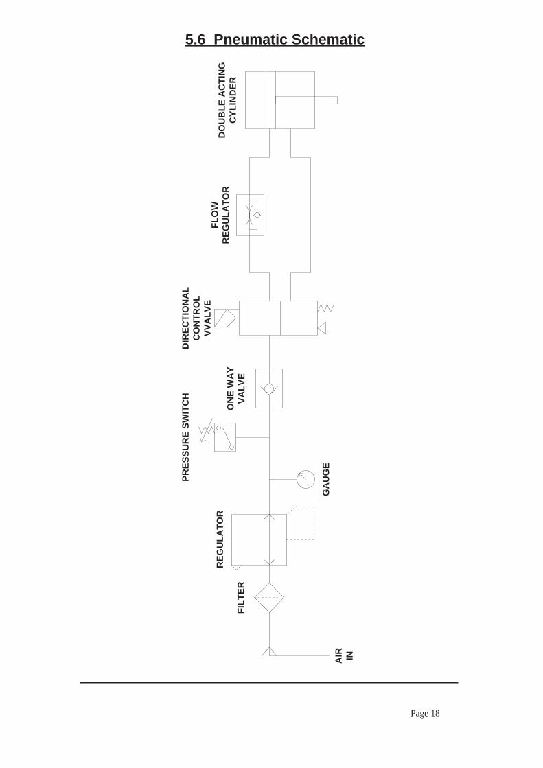
5.6 Pneumatic Schematic
FILT
ER
REG
ULA
TOR
PRES
SUR
E SW
ITC
HD
IREC
TIO
NA
LC
ON
TRO
LVV
ALV
EFL
OW
REG
ULA
TOR
GA
UG
E
ON
E W
AY
VALV
E
DO
UB
LE A
CTI
NG
CYL
IND
ER
AIR IN

Page 19
6. Design Change With the policy of constant improvement and/or modification to meet changing conditions, the right is reserved to change the design and/or specifications at any time without prior notification, and therefore specifications may vary and not be in accordance with this manual.

Page 20
7. Guarantee (Limited Warranty) A. Adkins & Sons Limited warrants that the press is free from defects in material and workmanship for a period of 12 months from the date of supply. The machine comes with a lifetime warranty on the heating element, one year warranty on parts and 90 days labour. This guarantee will only be effective when A. Adkins & Sons Limited authorises the original purchaser to return the machine to the factory, and only when the product upon examination has proven to be defective. Should in our opinion any part of this press be defective in materials or workmanship, it will be replaced or repaired free of charge, provided that the press has been installed and operated in the correct manner and not subjected to misuse. (This is excluding any travelling and/or carriage costs which will be charged at our discretion.) This guarantee does not apply to any machine that has been subjected to misuse, negligence, alteration or accident. A charge will be made for any costs incurred if a reported fault on the press is found to be due to incorrect installation, operation and/or incorrect materials being used. It is the responsibility of the press user to ensure the suitability of the materials operating through the press. In order for this guarantee to be effective, no return of machine or parts may be made without prior factory authorisation. No claim of any kind shall be greater in amount than the sale price of the product or part to which the claim is made. This is the sole guarantee given by the company, it is in lieu of any other guarantees, expressed or implied, in law or in fact, including the guarantees of merchantability and fitness for particular use, and is accepted as such by the purchaser in taking delivery of this product. A. Adkins & Sons Limited shall not be liable for any injury, loss or damage, direct or consequential, arising out of the use or the inability to use the product.

Page 21
A. ADKINS & SONS LIMITEDDECLARATION OF CONFORMITY
I, the undersigned, hereby declare that the equipment specified above conforms to the above directives and standards.
Place: Hinckley, United Kingdom Signature: ....................................
Date: .................................... Full Name: Marie McMahon Position: General Manager
Application of Council Directives: Machinery, Low Votage. E.M.C.
Standards to which Conformity isDeclared:
Manufacturer's Name: A. Adkins & Sons Limited
Manufacturer's Address: High Cross, 18 Lancaster Road, Hinckley, Leicester, LE10 0AW, United Kingdom.
Type of Equipment: Omega Series 500 Heat Press
Model Number: ..........................................................................................
Serial Number: ..........................................................................................
Year of Manufacture: ..........................................................................................
BS EN ISO 12100-1:2003+A1:2009 - Safety of machinery: Basic Technology.
BS EN ISO 12100-2:2003 - Safety of machinery: Principles of Design.
BS EN 60204-1:2006 - Safety of machinery: Electrical Equipment of Machines.
BS EN 60529:1992 - Degrees of protection provided by enclosures.
BS EN ISO 13850:2008 - Safety of machinery: Emergency Stops.
BS EN ISO 141211:2007 - Safety of machinery: Principles for Risk Assessment.
BS EN 55011:1998 - Class A Group 2 equipment - EMC Emissions.
BS EN ISO 61000-6-4:2007 - EMC Conducted Emissions.
BS EN ISO 61000-6-2:2005 - EMC Immunity.