omb approval 2700-0042 - nasa · web viewomb approval 2700-0042 1. this contract is a rated...
TRANSCRIPT

CONTRACT NAS9-97150 (EMU)
UPDATED: August 26, 2002
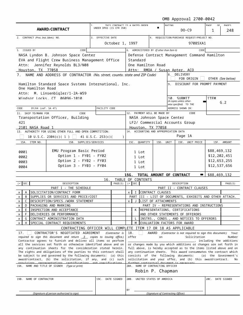
OMB Approval 2700-00421. THIS CONTRACT IS A RATED ORDER RATING PAGE OF PAGES
AWARD/CONTRACT UNDER DPAS (15 CFR 350) DO-C9 1 248
2. CONTRACT (Proc. Inst. Ident.) NO. 3. EFFECTIVE DATE 4. REQUISITION/PURCHASE REQUEST/PROJECT NO.
October 1, 1997 97085XA1
5. ISSUED BY CODE 6. ADMINISTERED BY (If other than Item 6) CODE
NASA Lyndon B. Johnson Space CenterEVA and Flight Crew Business Management OfficeAttn: Jennifer Reynolds BL3/N08Houston, TX 77058
Defense Contract Management Command Hamilton StandardOne Hamilton RoadAttn: RMOA / Susan Apter, ACOWindsor Locks, CT 06096-0463
7. NAME AND ADDRESS OF CONTRACTOR (No. street, county, state and ZIP Code) 8. DELIVERY FOB ORIGIN OTHER (See below)
Hamilton Standard Space Systems International, Inc. 9. DISCOUNT FOR PROMPT PAYMENTOne Hamilton RoadAttn: M. Linsenbigler/1-2A-W59Windsor Locks, CT 06096-1010 10. SUBMIT ITEM
(4 copies unless other-wise specified) TO THE G.2
CODE OYJV4 (ref. SA 47) FACILITY CODE ADDRESS SHOWN IN:
11. SHIP TO/MARK FOR CODE 12. PAYMENT WILL BE MADE BY CODE
Transportation Officer, Building 4212101 NASA Road 1Houston, TX 77058 -3696
NASA Johnson Space CenterLF2/ Commercial Accounts GroupHouston, TX 77058
13. AUTHORITY FOR USING OTHER FULL AND OPEN COMPETITION:
10 U.S.C. 2304(c)( 1 ) 41 U.S.C. 253(c)( )14. ACCOUNTING AND APPROPRIATION DATA
Page 1A
15A. ITEM NO. 15B. SUPPLIES/SERVICES 15C. QUANTITY 15D. UNIT 15E. UNIT PRICE 15F. AMOUNT
0001000200030004
EMU Program Basic Period Option 1 - FY01 - FY02 Option 2 - FY02 - FY03 Option 3 - FY03 - FY04
1 Lot 1 Lot1 Lot1 Lot
$88,469,132 $12,202,451 $12,653,255 $12,537,656
15G. TOTAL AMOUNT OF CONTRACT $88,469,13216. TABLE OF CONTENTS
() SEC. DESCRIPTION PAGE(S) () SEC. DESCRIPTION PAGE(S)
PART I - THE SCHEDULE PART II - CONTRACT CLAUSESx A SOLICITATION/CONTRACT FORM x I CONTRACT CLAUSESx B SUPPLIES OR SERVICES AND PRICE/COST PART III - LIST OF DOCUMENTS, EXHIBITS AND OTHER ATTACH.x C DESCRIPTION/SPECS./WORK STATEMENT x J LIST OF ATTACHMENTSx D PACKAGING AND MARKING PART IV - REPRESENTATIONS AND INSTRUCTIONSx E INSPECTION AND ACCEPTANCE K REPRESENTATIONS, CERTIFICATIONS x F DELIVERIES OR PERFORMANCE AND OTHER STATEMENTS OF OFFERORSx G CONTRACT ADMINISTRATION DATA L INSTRS., CONDS., AND NOTICES TO OFFERORSx H SPECIAL CONTRACT REQUIREMENTS M EVALUATION FACTORS FOR AWARD
CONTRACTING OFFICER WILL COMPLETE ITEM 17 OR 18 AS APPLICABLE17. CONTRACTOR’S NEGOTIATED AGREEMENT (Contractor is required to sign this document and return __3___ copies to issuing office.) Contractor agrees to furnish and deliver all items or perform all the services set forth or otherwise identified above and on any continuation sheets for the consideration stated herein. The rights and obligations of the parties to this contract shall be subject to and governed by the following documents: (a) this award/contract, (b) the solicitation, if any, and (c) such provisions, representations, certifications, and specifications, as are attached or incorporated by reference herein. (Attachments are listed herein.)
18. AWARD (Contractor is not required to sign this document.) Your offer on Solicitation Number _________________________________________, including the additions or changes made by you which additions or changes are set forth in full above, is hereby accepted as to the items listed above and on any continuation sheets. This award consummates the contract which consists of the following documents: (a) the Government’s solicitation and your offer, and (b) this award/contract. No further contractual document is necessary.
19A. NAME AND TITLE OF SIGNER (Type or print) 20A. NAME OF CONTRACTING OFFICER
Robin P. Chapman
19B. NAME OF CONTRACTOR 19C. DATE SIGNED 20B. UNITED STATES OF AMERICA 20C. DATE SIGNED
________________________________________________(Signature of person authorized to sign)
BY _____________________________________________(Signature of Contracting Officer)
NSN 7540-01-152-8069 26-107 STANDARD FORM 26 (REV. 4-5)

PREVIOUS EDITION UNUSABLE Computer Generated Prescribed by GSAFAR (48 CFR) 53.214(a)
Contract NAS 9-97150 Page 1A
Purchase Request Accounting And Appropriation Data Amount 97085XA2 260-11-01-25-6A-XA6171-XA11 807/80111 $3,000,00097085XA1 250-11-01-24-6A-XA6171-XA11 807/80111 $300,00097220EC1 477-72-EV-05-5A-EC2550-EC51 807/80111 $40,000

TABLE OF CONTENTS
Section A - Solicitation/Contract Standard Form 33
A.1 - Detailed Table Of Contents
Section B - Supplies Or Services And Prices/Costs
B. 1 - Listing Of Clauses Incorporated By ReferenceB. 2 - Scope Of WorkB. 3 - Estimated Cost And Fee ArrangementB. 4 - Contract Funding (NASA 18-52.232-81) (Jun 1990)B. 5 - Fee Structure
Section C - Statement Of Work
Section D - Packaging And Marking
D. 1 - Listing Of Clauses Incorporated By ReferenceD. 2 - Packaging And Marking
Section E - Inspection And Acceptance
E.1 - Listing Of Clauses Incorporated By ReferenceE.2 - Preliminary Inspection At Source And Final Inspection And Acceptance At
DestinationE.3 - Evaluation And AcceptanceE.4 - Quality Assurance Surveillance Plan (JSC 52.246-93) (July 1996)
Section F - Deliveries Or Performance
F.1 - Listing Of Clauses Incorporated By ReferenceF.2 - Option To Extend Competion Date (JSC 52.217-90) (Oct 1996)F.3 - Stop-Work Order (JSC 52.242-15) (Aug 1989)--Alternate I (Apr 1984)F.4 - Delivery ScheduleF.5 - Shipment by Government Bills of Lading (NASA 18-52.247-73) (Mar 1997)F.6 - Shipping Instructions (JSC 52.247-94) (Oct 1993)F.7 - Flight Item (JSC 52.247-95) (Sep 1989)
Section G - Contract Administration Data
G.1 - Listing Of Clauses Incorporated By ReferenceG.2 - Submission Of Invoices (JSC 52.232-90) (Oct 1993)G.3 - Technical Direction (NASA 18-52.242-70) (Sep 1993)G.4 - Limitation on Payment of Award Fee G.5 - Award Fee For End Item Contracts (1852.216-77) Jan 1997) G.6 - Small Business, Small Disadvantaged Business, And Women-Owned
Small Business Concerns
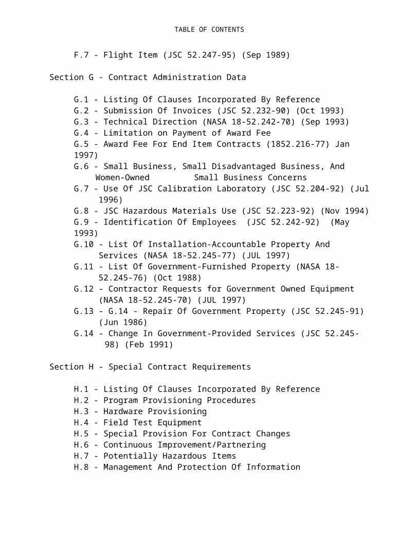
TABLE OF CONTENTS
G.7 - Use Of JSC Calibration Laboratory (JSC 52.204-92) (Jul 1996)G.8 - JSC Hazardous Materials Use (JSC 52.223-92) (Nov 1994)G.9 - Identification Of Employees (JSC 52.242-92) (May 1993)G.10 - List Of Installation-Accountable Property And Services (NASA 18-52.245-
77) (JUL 1997)G.11 - List Of Government-Furnished Property (NASA 18-52.245-76) (Oct 1988)G.12 - Contractor Requests for Government Owned Equipment (NASA 18-
52.245-70) (JUL 1997)G.13 - G.14 - Repair Of Government Property (JSC 52.245-91) (Jun 1986)G.14 - Change In Government-Provided Services (JSC 52.245-98) (Feb 1991)
Section H - Special Contract Requirements
H.1 - Listing Of Clauses Incorporated By ReferenceH.2 - Program Provisioning ProceduresH.3 - Hardware Provisioning H.4 - Field Test EquipmentH.5 - Special Provision For Contract ChangesH.6 - Continuous Improvement/PartneringH.7 - Potentially Hazardous Items H.8 - Management And Protection Of InformationH.9 - Special Agreement Regarding Independent Research And Development
(IR&D)H.10 - Safety And Health PlanH.11 - Government InsightH.12 - Engineering Change ProposalsH.13 - Space Flight Motivation Awareness ProgramH.14 - Human Space Flight Item (NASA 18-52-246-73) (Mar 1997)H.15 - Requirement For Cost TrackingH.16 - Key Personnel (NASA 18-52.235-71) (Mar 1989)H.17 - Representations, Certifications, And Other Statements Of Offerors (JSC
52.209-90) (September 1988)
Section I - Contract Clauses
I.1 - Listing Of Clauses Incorporated By Reference I.2 - APPROVAL OF CONTRACT (52.204-1)I.3 - Limitation On Withholding Of Payments (52.232-9) (Apr 1984I.4 - Clauses Incorporated By Reference (52.252-2) (Jun 1988)I.5 - Alterations In Contract (52.252-4) (Apr 1984
Section J - Lists Of Attachments
J-1 - Data Requirements List (DRL) & Data Requirements Documents (DRD's)J-2 - Program Management PlanJ-3 - Contract Metrics

TABLE OF CONTENTS
J-4 - Performance (Fee) PlanJ-5 - Program ProvisioningJ-6 - Hardware Quantities And Delivery SchedulesJ-7 - Hardware Refurbishment Quantities And SchedulesJ-8 - Hardware Provisioning ListJ-9 - Safety And Health PlanJ-10 - Government Furnished PropertyJ-11 - Installation Provided ServicesJ-12 - Applicable DocumentsJ-13 - NAS 9-17873 Carry-Over EffortJ-14 - Quality PlanJ-15 - Subcontracting Plan

SECTION C
STATEMENT OF WORK
B.1 LISTING OF CLAUSES INCORPORATED BY REFERENCE
NOTICE: The following solicitation provisions and/or contract clauses pertinent to this section are hereby incorporated by reference:
I. FEDERAL ACQUISITION REGULATION (48 CFR CHAPTER 1) -
No FAR By-reference clauses in Section B.
II. NASA FEDERAL ACQUISITION REGULATION SUPPLEMENT (48 CFR CHAPTER 18) -
No NASA By-reference clauses in Section B.
B-2 SCOPE OF WORK
The Contractor shall provide Extravehicular Mobility Unit (EMU) hardware, life extension, system enhancement, field activities, safety and mission assurance and program management and engineering in accordance with the Statement of Work, (Section C) during a 4-year base contract period beginning October 1, 1997 plus, if exercised, 3, 1-year option periods (for a total potential period of performance of 7 years).
Engineering, design, and development, hardware production, life extension activities, safety and mission assurance, and program provisioning shall fall under the Cost-Plus- Award-Fee provision of this contract. All contract costs (excluding program provisioning and Firm-Fixed-Price provisions) shall fall under the Cost-Plus-Incentive-Fee provision of this contract. Hardware provisioning shall fall under the Firm-Fixed-Price or Cost- Plus-Incentive-Fee arrangement of the contract, as appropriate.
The contractor shall complete all work carried-over from contract NAS 9-17873 in accordance with the SOW, Section C, hereof and Section J-13
B.3 ESTIMATED COST AND FEE ARRANGEMENT:

SECTION C
STATEMENT OF WORK
Contract Cost and Fee Summary: Ref. SA 414 I. Baseline:
A. Cost Reimbursement Revised Contract Value
Cost Est. Target Cost $178,684,639 Est. Program Provisioning $11,700,000 Delivery Orders $49,302,473 Total Est. Cost $239,687,112
Fee Target Incentive Fee* $13,226,201 Maximum Award Fee $10,492,370 Maximum Fee @ Target Cost $23,718,571 Minimum Incentive Fee* $2,377,611
Maximum Total Fee** $34,129,641
Total Cost and Fee $263,405,683
B. Firm-Fixed Price $970,030
C. Total Contract Value Baseline $264,375,713
Carryover:A. Cost Reimbursement Est. Cost (FP) $15,171,853 Est. Planar HUT Target Cost $8,007,386 Fixed Fee $1,046,849 Target Planar HUT Fee $549,355
Total Cost and Fee $24,775,443
B. Firm-Fixed Price $5,137,939
C. Total Contract Value Carryover $29,913,382
III. Total Contract Value $294,289,095
* Subject to the award fee performance gate included under Section J-4, Performance Evaluation (Fee) Plan

SECTION C
STATEMENT OF WORK
** Includes all fees payable under the contract which are not to exceed 15% of estimated contract cost less cost of money.
Contract Cost and Fee Summary:I. Option 2 (Ref. SA 365)
RevisedContract Value
I. OPTION 2 A. Cost Reimbursement Cost Est. Target Cost $17,025,286 Est. Program Provisioning $0 Delivery Orders $0 Total Est. Cost $17,025,286
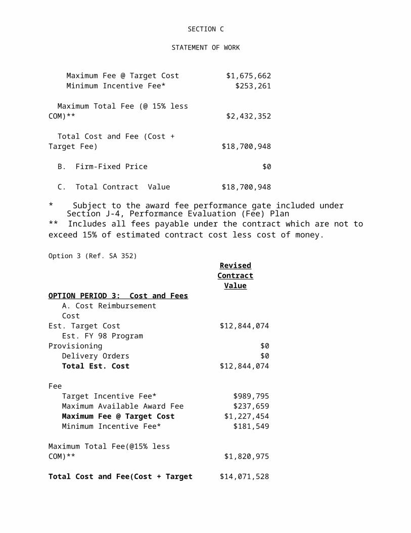
Fee Target Incentive Fee* $1,355,705 Maximum Award Fee $319,957 Maximum Fee @ Target Cost $1,675,662 Minimum Incentive Fee* $253,261
Maximum Total Fee (@ 15% less COM)** $2,432,352
Total Cost and Fee (Cost + Target Fee) $18,700,948
B. Firm-Fixed Price $0
C. Total Contract Value $18,700,948
* Subject to the award fee performance gate included under Section J-4, Performance Evaluation (Fee) Plan
** Includes all fees payable under the contract which are not to exceed 15% of estimated contract cost less cost of money.
Option 3 (Ref. SA 352)Revised Contract
ValueOPTION PERIOD 3: Cost and Fees A. Cost Reimbursement CostEst. Target Cost $12,844,074

SECTION C
STATEMENT OF WORK
Est. FY 98 Program Provisioning $0 Delivery Orders $0 Total Est. Cost $12,844,074 Fee Target Incentive Fee* $989,795 Maximum Available Award Fee $237,659 Maximum Fee @ Target Cost $1,227,454 Minimum Incentive Fee* $181,549
Maximum Total Fee(@15% less COM)** $1,820,975
Total Cost and Fee(Cost + Target Fee) $14,071,528
B. Firm-Fixed Price $0
C. Total Option Value $14,071,528
Plan.cost of money. * Subject to the award fee performance gate included under Section J-4,
Performance Evaluation (Fee) Plan ** Includes all fees payable under the contract which are not to exceed 15% of estimated contract cost less cost of money.
(Ref. SA 398)B.4 CONTRACT FUNDING (NASA 18.52.232-81) (JUN 1990)
(a) For purposes of payment of cost, exclusive of fee, in accordance with the Limitation of Funds Clause, the total amount allotted by the Government to this contract is
(b) $232,822110.00 . This allotment is for the EMU Program Contract and covers the following period of performance: October 1, 1997 through September 15, 2002.
(c) An additional amount of $24.175,816.00 is obligated under this contract for payment of fee.
2. Cumulative funding to date is summarized as follows:
Prior Cum Obligation This Obligation Revised Cum Obligation
$232,722,210.00 $99,900.00 $232,822,110.00$ 24,164,716.00 $ 11,100.00 $ 24,175,816.00$256,886,926.00 $111,000.00 $256,997,926.00
SECTION C
STATEMENT OF WORK
3. Purchase Request # Accounting Code & Appropriation Data Amount 02115EC1 721-30-40-CO-5A-EC2550-EC31 $111,000
Total: $111,000
All other terms and conditions on the contract remain the same.
B.5 FEE STRUCTURE
See Performance Evaluation (Fee) Plan, Section J-4

SECTION C
STATEMENT OF WORK
TABLE OF CONTENTS
LIST OF ACRONYMS
1.0 EXTRAVEHICULAR MOBILITY UNIT PROGRAM CONTRACT
1.1 Program and Business Management
1.1.1 Planning
1.1.2 Earned Value Performance Measurement System
1.1.3 Metrics
1.1.4 Configuration Management and Control
1.1.5 Data Management 11
1.1.6 Program Reviews
1.1.6.1 Program Management Reviews1.1.6.2 Technical and Business Meetings
1.1.7 Financial and Resources Management
1.1.7.1 Financial Management
1.1.7.2. Resources Management
1.1.7.3 Subcontract Management1.1.7.4 Property Management
1.1.8 Partnering
2.0 ENGINEERING
2.1 Systems Engineering and Integration
2.1.1 Interfaces2.1.2 Hardware Development and Certification Testing
2.2 Program Provisioning
2.2.1. Field Activities2.2.2. EVA Preflight and Real-Time Mission Support2.2.3. Special Studies2.2.4. Special Testing2.2.5. Supplier Supportability / Obsolescence
2.3 EMU Enhancements
2.4. Anomaly Analysis

SECTION C
STATEMENT OF WORK
3.0 HARDWARE
3.1 Hardware Provisioning
3.2 Hardware Refurbishment
3.3 Hardware Rework and Repair
3.4 Pre-delivery Acceptance (PDA) Testing
3.5 Tooling, Special Test Equipment (STE) and Government-Furnished Property (GFP)
3.6 Transportation, Shipping & Receiving, Warehousing, and Distribution
4.0 ASSURED EMU AVAILABILITY (AEA) PROGRAM
4.1 Life Extension
4.2 Supplier Supportability
4.3 Technology Obsolescence
4.4 Provisioning Planning System
4.5 Environmental, Health, and Safety Compliance
4.5.1 Hazardous Waste4.5.2 Ozone Depleting Substance (ODS) Phase-out
5.0 SAFETY, MISSION ASSURANCE, AND PRODUCT ASSURANCE
5.1 Safety
5.1.1 Systems Safety5.1.2 Operations Safety
5.2 Mission Assurance
5.3 Product Assurance
5.3.1 Quality Assurance5.3.2 Product and Service Quality5.3.3 Process Quality
5.4 Waivers or Deviations 25

SECTION C
STATEMENT OF WORK
LIST OF ACRONYMS
A/L AIRLOCK INCORPORATEDAAP AIRLOCK ADAPTER PLATEACO AIRCRAFT CENTRAL OPERATIONSACR AUTHORIZED CHANGE RECORDADP ACCEPTANCE DATA PACKAGEAFEB AWARD FEE EVALUATION BOARDALSS AIRLOCK SUPPORT SUBSYSTEMARC AMES RESEARCH CENTERASD AIRCRAFT SYSTEMS DEPARTMENTATP ACCEPTANCE TEST PLAN (OR PROCEDURE)ATP AUTHORIZATION TO PROCEEDBAO/ BOEING AEROSPACE OPERATIONS/FLIGHT EQUIPMENT B&P BUDGETARY & PLANNING (ESTIMATE)BH/M BREATHER HOSE/MOUTHPIECEBIS BIOINSTRUMENTATION SYSTEMBITE BUILT IN TEST EQUIPMENTBRA BENDS RECOVERY APPARATUSBSC BODY SEAL CLOSUREBTA BENDS TREATMENT ADAPTERBTU BRITISH THERMAL UNITCCA COMMUNICATIONS CARRIER ASSEMBLYCCB CONFIGURATION CONTROL BOARDCCBD CONFIGURATION CONTROL BOARD DIRECTIVECCC CONTAMINANT CONTROL CARTRIDGECCO CONTRACT CHANGE ORDERCDR CRITICAL DESIGN REVIEWCEI CONTRACT END ITEMCERT CERTIFICATION TESTCET COMBINED ELECTRICAL TEST RIGCFE CONTRACTOR FURNISHED EQUIPMENTCIL CRITICAL ITEMS LISTCOL CONTRACTING OFFICER LETTERCPFF/AF COST PLUS FIXED FEE/AWARD FEECPPHSS CLEANING, PRESERVATION, PACKAGING, HANDLING, SHIPPING, &
STORAGE PROCEDURESCPV COMBINATION PURGE VALVECRM CUSTOMER RETURNED MATERIALCRT CATHODE RAY TUBECTSD CREW AND THERMAL SYSTEMS DIVISION (NASA JSC)CWS CAUTION & WARNING SYSTEMCY CALENDAR YEARDACT DISPOSABLE ABSORBENT CONTAINMENT TRUNKDCAA DEFENSE CONTRACT AUDIT AGENCYDCAS DEFENSE CONTRACT ADMINISTRATION SERVICEDCM DISPLAY & CONTROLS MODULEDCN DOCUMENT CHANGE NOTICEDDT&E DESIGN, DEVELOPMENT, TEST & EVALUATION

SECTION C
STATEMENT OF WORK
DFT DESIGN FEASIBILITY TESTDMRV DUAL MODE RELIEF VALVEDOD DEPARTMENT OF DEFENSEDOT DEPARTMENT OF TRANSPORTATIONDR DISCREPANCY REPORTDRD DATA REQUIREMENT DESCRIPTIONDRL DATA REQUIREMENTS LISTDST DESIGN SUPPORT TESTINGDTO DETAILED TEST OBJECTIVEDVT DESIGN VERIFICATION TESTEAC ESTIMATE AT COMPLETIONEB ELECTRON BEAM WELDINGEC ENGINEERING CHANGEECG ELECTROCARDIOGRAMECO ENGINEERING CHANGE ORDERECP ENGINEERING CHANGE PROPOSALECRA ENGINEERING CHANGE REQUEST AND ANALYSISECS ENVIRONMENTAL CONTROL SYSTEMEEE ELECTRONIC, ELECTRICAL, AND ELECTROMECHANICALEEH EMU ELECTRICAL HARNESSEEPC FLIGHT EQUIPMENT PROCESSING CONTRACTEES EJECTION ESCAPE SUITEM ENGINEERING MEMORANDUMEMI ELECTROMAGNETIC INTERFERENCEEMU EXTRAVEHICULAR MOBILITY UNITESCU EXTENDED SERVICE & COOLING UMBILICALESS ENVIRONEMENTAL & SPACE SYSTEMS DEPARTMENTESVS ESCAPE SUIT VENTILATION SYSTEMETC ESTIMATE TO COMPLETEEV EXTRAVEHICULAREVA EXTRAVEHICULAR ACTIVITYEVA ETHYLENEVINYLACETATEEVC EXTRAVEHICULAR COMMUNICATIONS SYSTEMEVCA EXTRAVEHICULAR COMMUNICATIONS ADAPTEREVCS EXTRAVEHICULAR COMMUNICATIONS SYSTEM (EVC PREFERRED)EVCU EXTRAVEHICULAR COMMUNICATIONS UMBILICALEVOU EXTRAVEHICULAR OXYGEN UMBILICALEVVA EXTRAVEHICULAR VISOR ASSEMBLYEWRS EMU WEIGHT RELEASE SYSTEMF/P/S FAN/PUMP/SEPARATOR ASSEMBLYFACI FIRST ARTICLE CONFIGURATION INSPECTIONFCCP FIRM CONTRACT CHANGE PROPOSALFDO FEE DETERMINATION OFFICERFEPC PROCESSING CONTRACT
FIAR FAILURE INVESTIGATION AND ANALYSIS REPORTFMEA FAILURE MODES & EFFECTS ANALYSISFMOF FIRST MANNED ORBITAL FLIGHTFRR FLIGHT READINESS REVIEW

SECTION C
STATEMENT OF WORK
FTE FIELD TEST EQUIPMENTFTS FEDERAL TELECOMMUNICATIONS SYSTEMFW FEEDWATERFY FISCAL YEARG&A GENERAL & ADMINISTRATIVE (EXPENSE)GBL GOVERNMENT BILL OF LADINGGFE GOVERNMENT FURNISHED EQUIPMENTGFM GOVERNMENT FURNISHED MATERIALGFP GOVERNMENT FURNISHED PROPERTYGFY GOVERNMENT FISCAL YEARGHD GROUND HANDLING DEVICEGSA GENERAL SERVICES ADMINISTRATIONGSE GROUND SUPPORT EQUIPMENT (EMU USES FTE AS DESIGNATION)GSFC GODDARD SPACE FLIGHT CENTERGSI GOVERNMENT SOURCE INSPECTIONHI-FI HIGH FIDELITY (MOCK-UP)HS HAMILTON STANDARD DIVISION OF UNITED TECHNOLOGIES
CORPORATIONHSD HAMILTON STANDARD (HS IS PREFERRED)HSMS HAMILTON STANDARD MANAGEMENT SERVICES, INC.HSS HAMILTON SUPPORT SYSTEMSHSSSI HAMILTON STANDARD SPACE SYSTEMS INTERNATIONALHTS HARD TORSO SHELLHUT HARD UPPER TORSOHX HEAT EXCHANGERICD INTERFACE CONTROL DOCUMENTIDB INSUIT DRINK BAGIG INSPECTOR GENERALILC ILC-DOVER, DIVISION OF ILC INDUSTRIESIPAR IRREGULAR PARTS APPLICATION REQUESTIPL ILLUSTRATED PARTS LISTIPT IN-PROCESS TESTIR INFRAREDIR INSULATION RESISTANCE TESTIR&D INDEPENDENT RESEARCH AND DEVELOPMENTIRN INTERFACE REVISION NOTICEITMG INTEGRATED THERMAL METEOROID GARMENTIV INTRAVEHICULARJSC JOHNSON SPACE CENTERKSC KENNEDY SPACE CENTERL LARGE (SSA SIZE)LCD LIQUID CRYSTAL DISPLAYLCG LIQUID COOLANT GARMENT (APPOLLO USAGE)LCVG LIQUID COOLING & VENTILATION GARMENTLED LIGHT EMITTING DIODELLL LIMITED LIFE LISTLOC LIMITATION OF COSTLOGO LIMATION OF GOVERNMENT'S OBLIGATIONLSS LIFE SUPPORT SUBSYSTEM

SECTION C
STATEMENT OF WORK
LTA LOWER TORSO ASSEMBLYLVD LEG VENT DUCTLW LIGHT WEIGHT (MOCK-UP)M/U MOCK-UPMAC MAXIMUM ALLOWABLE CONCENTRATIONMACR MASTER AUTHORIZED CHANGE RECORDMATCO MATERIALS COMPATIBILITY (STANDARD MATERIALS WORKSHEETS)MED MEDIUM (SSA SIZE)MFR MANIPULATOR FOOT RESTRAINTMH MAN-HOURMIP MANDATORY INSPECTION POINTMM MAN-MONTHMMA MARTIN MARIETTA AEROSPACEMMU MANNED MANEUVERING UNITMODEM MODULATION/DEMODULATIONMR MATERIAL REVIEWMRA MATERIAL REJECTION ANALYSISMSFC MARSHALL SPACE FLIGHT CENTERMTBF MEAN TIME BETWEEN FAILURESMWC MULTIPLE WATER CONNECTORMWS MINI-WORK STATIONN-R NONRECURRINGN/A NOT APPLICABLEN/C NO CHANGEN/R NOT REQUIREDNASA NATIONAL AERONAUTICS & SPACE ADMINISTRATIONNB NEUTRAL BUOYANCY (MOCK-UP)NPU NITROGEN PURGE UNITODC OTHER DIRECT COSTOEH OXYGEN EXTENSION HOSEOFT ORBITAL FLIGHT TESTOH OVERHEAD (EXPENSE)OPA OXYGEN PURGE ADAPTEROPS OXYGEN PURGE SYSTEM (APOLLO USAGE)ORI OPERATIONAL READINESS INSPECTIONORU ON-ORBIT UNITOSB OBRITER STOWAGE BRACKETP&W PRATT & WHITNEY AIRCRAFTP/N PART NUMBERPD PROGRAM DIRECTIVEPDA PREDELIVERY ACCEPTANCE TESTPDR PRELIMINARY DESIGN REVIEWPEAP PAD EMERGENCY AIR PACKPGA PRESSURE GARMENT ASSEMBLYPIA PREINSTALLATION ACCEPTANCE TESTPLSS PRIMARY LIFE SUPPORT SUBSYSTEMPMO PROGRAM MANAGEMENT OFFICEPO PURCHASE ORDERPOP PROGRAM OPERATING PLAN

SECTION C
STATEMENT OF WORK
POR PURCHASE ORDER REQUESTPOS PORTABLE OXYGEN SYSTEMPPH POUNDS PER HOURPPM PARTS PER MILLIONPR PROCUREMENT REGULATIONPRACA PROBLEM REPORTING AND CORRECTIVE ACTIONPRE PERSONNEL RESCUE ENCLOSUREPROM PROGRAMMABLE READ-ONLY MEMORYPSI POUNDS PER SQUARE INCHPSIA POUNDS PER SQUARE INCH ABSOLUTEPSID POUNDS PER SQUARE INCH DIFFERENTIALPTT PUSH-TO-TALK (SWITCH ON DCM)PVC POLYVINYLCHLORIDEPVU PATTERN VERIFICATION UNITQA QUALITY ASSURANCEQD QUICK DISCONNECTRAM RANDOM ACCESS MEMORYRBA REBREATHER ASSEMBLYRDR RELIABILITY DATA REPORTRECP REQUEST FOR ENGINEERING CHANGE PROPOSALREV REVISIONRFP REQUEST FOR PROPOSALRI ROCKWELL INTERNATIONALRID REVIEW ITEM DISPOSITIONRK RECHARGE KITROM READ-ONLY MEMORYROM ROUGH ORDER OF MAGNITUDE (ESTIMATE)RSPL RECOMMENDED SPARES PROVISIONING LISTRTOP RESEARCH & TECHNOLOGY OPERATING PLANS SMALL (SSA SIZE)S/AD SPECIFICATION/ASSEMBLY DRAWINGS/N SERIAL NUMBERSCC STANDARD CUBIC CENTIMETERSSCU SERVICE AND COOLING UMBILICALSEM SCANNING ELECTRON MICROSCOPESEMU SHORT EMUSEMU SHUTTLE EXTRAVEHICULAR MOBILITY UNITSESL SPACE ENVIRONMENT SIMULATION LABORATORYSEVA SKYLAB EXTRAVEHICULAR VISOR ASSEMBLYSMP SPECIAL MAJOR PROCUREMENT (EXPENSE)SOP SECONDARY OXYGEN PACKSOW STATEMENT OF WORKSPF SINGLE POINT FAILURESR&QA SAFETY, RELIABILITY, & QUALITY ASSURANCESSA SPACE SUIT ASSEMBLYSSD SPACE SYSTEMS DEPARTMENT (CHANGED TO ESS)SSF SPACE STATION FREEDOMSSP SPACE SHUTTLE PROGRAMSTE SPECIAL TEST

SECTION C
STATEMENT OF WORK
SVU SIZING VERIFICATION UNITSWL SINGLE WALL LAMINATEST/S TEST STANDTBD TO BE DETERMINEDTCS THERMAL CONTROL SYSTEMTD TECHNICAL DIRECTIONTIG TUNGSTEN INERT GAS (WELDING)TM TECHNICAL MONITORTMG THERMAL METEOROID GARMENTTPS TEST PREPARATION SHEETTRR TEST READINESS REVIEWUCD URINE COLLECTION DEVICEUCS UNIT COST STUDYUMP UNIQUE MAJOR PROCUREMENT (EXPENSE)USAF UNITED STATES AIR FORCEUTC UNITED TECHNOLOGIES CORPORATIONUTMC UNITED TECHNOLOGIES MICROELECTRONICS CENTERUTRC UNITED TECHNOLOGIES RESEARCH CENTERUV ULTRAVIOLETVAFB VANDENBERG AIR FORCE BASEVAT VIBRATION ACCEPTANCE TESTVDC VOLTS DIRECT CURRENTVFS VENT FLOW SENSORWBS WORK BREAKDOWN STRUCTUREWETF WEIGHTLESS ENVIRONMENT TEST FACILITY (JSC)WIF WATER IMMERSION FACILITY (MSFC)WPD WORK PACKAGE DESCRIPTIONWPI WORK PACKAGE INSTRUCTIONWSTF WHITE SANDS TEST FACILITYXL EXTRA-LARGE (SSA SIZE)XS EXTRA-SMALL (SSA SIZE)ZPS ZERO PREBREATHE SYSTEM

SECTION C
STATEMENT OF WORK
1.0 Extravehicular Mobility Unit Program Contract
This statement of work defines the requirements that shall be met by the contractor in the accomplishment of the NASA EMU Program, as described herein. The contractor shall be responsible for the overall successful performance of the EMU Program, and unless otherwise stated, shall provide all necessary personnel, materials, equipment, and facilities, to meet contract requirements. Specific requirements include, but are not limited to: program and business management; engineering; design, develop, certification, production and enhancement of EMU and other EVA related hardware; assured EMU availability program, field activities, and safety, mission assurance, reliability, and quality assurance programs. The contractor shall support the Space Shuttle Program (SSP) and the International Space Station Program (ISS), including activities within those programs involving payloads and international partners.
The EMU was originally designed, developed, certified, and fabricated by United Technologies Corporation, Hamilton Standard Division, under NASA Contract Numbers NAS 9-15150 and NAS 9-17873. The intent of this contract is to provide for the continuation of the EMU Program and to provide for the evolution of the EMU design as mandated by NASA’s changing program requirements. The contractor shall be responsible for the design, development, fabrication and certification of the EMU and EVA related equipment, and therefore, is ultimately responsible for its flight worthiness, both as it was developed and certified under Contracts NAS 9-15150 and NAS 9-17873, and as it may be modified by tasks authorized under this contract.
The contractor shall provide the resources, including subcontractor and vendor participation, to fully complete all tasks previously authorized under Contract NAS 9-17873 which are identified in section J-13 - NAS 9-17873 Carry Over Effort. Section J-13 is attached to and is made a part of this statement of work.
EMU performance, workmanship and design shall reflect the applicable requirements of Volume X of NSTS 07700 Shuttle Flight and Ground Systems Specifications, and other applicable documents delineated in Section J-12 - Applicable Documents which is attached to and is made a part of this statement of work.
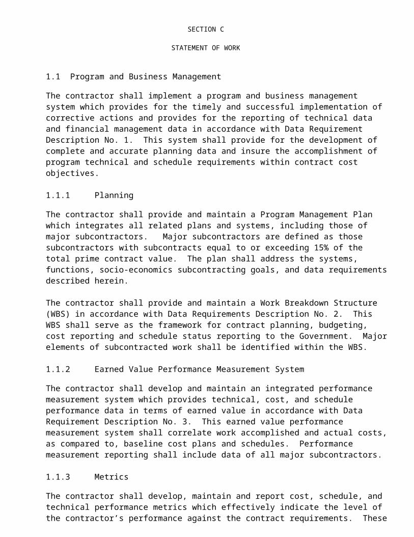
1.1Program and Business Management
The contractor shall implement a program and business management system which provides for the timely and successful implementation of corrective actions and provides for the reporting of technical data and financial management data in accordance with Data Requirement Description No. 1. This system shall provide for the development of complete and accurate planning data and insure the accomplishment of program technical and schedule requirements within contract cost objectives.
1.1.1 Planning
The contractor shall provide and maintain a Program Management Plan which integrates all related plans and systems, including those of major subcontractors. Major subcontractors are defined as those subcontractors with subcontracts equal to or exceeding 15% of the total prime contract value. The plan shall address the systems, functions, socio-economics subcontracting goals, and data requirements described herein.

SECTION C
STATEMENT OF WORK
The contractor shall provide and maintain a Work Breakdown Structure (WBS) in accordance with Data Requirements Description No. 2. This WBS shall serve as the framework for contract planning, budgeting, cost reporting and schedule status reporting to the Government. Major elements of subcontracted work shall be identified within the WBS.
1.1.2 Earned Value Performance Measurement System
The contractor shall develop and maintain an integrated performance measurement system which provides technical, cost, and schedule performance data in terms of earned value in accordance with Data Requirement Description No. 3. This earned value performance measurement system shall correlate work accomplished and actual costs, as compared to, baseline cost plans and schedules. Performance measurement reporting shall include data of all major subcontractors.
1.1.3 Metrics
The contractor shall develop, maintain and report cost, schedule, and technical performance metrics which effectively indicate the level of the contractor’s performance against the contract requirements. These metrics shall include definition and analysis as defined in Data Requirement Description No. 4.
1.1.4 Configuration Management and Control
The contractor shall establish and maintain a configuration management (CM) system in accordance with Data Requirement Description No. 5. This shall include the identification, control, and accounting for hardware and software for which the contractor is responsible for under the contract. The contractor shall provide configuration management products, including creation and maintenance of a Authorized EMU Configuration List (AECL), engineering drawings and associated parts lists; verification of “as-built” to “as-designed“ configuration of contract hardware; materials analysis; and engineering change documentation such as, Engineering Change Orders, Certification Impact and Analysis Reports (CIAR. In addition, the contractor shall prepare and coordinate EVA Hardware Board and EVA Configuration Control Board directives, waivers, and deviations, and maintain accurate, complete, and current configuration management data to ensure the implementation and verification of program direction.
Ref. SA 301.1.4.1
A Class II Engineering Change is required revising the drawing to reflect the vendor's name and address change for the 02 Frame and Filter Assemblies P/N SV778902-1.
1.1.1.5 Data Management The contractor shall provide a data management plan in accordance with Data Requirement Description No. 6 This plan shall describe the management, preparation, control, and dissemination of data required under this contract. In addition this plan shall define an integrated approach for data management including management of documentation (in any media), automated databases, and related products.

SECTION C
STATEMENT OF WORK
The contractor shall describe the areas of the contractor’s internal data systems where the Government will be permitted on-line access (“look-in”) and shall define access and interface requirements and provide the Government with required training to be able to access and use these systems. In addition, the plan will describe an approach for maintaining an on-line, conformed copy of the contract which will be revised, by the contractor, as changes to the contract are implemented. Electronic data processing, transmission and record keeping shall be used to increase efficiency and cost effectiveness.
1.1.6 Program Reviews
1.1.6.1 Program Management Reviews
The contractor shall conduct Program Management Reviews (PMR’s) to provide the Government with current status of the contractor’s financial and technical activities under the contract. PMR’s shall be conducted 3 times per year. Content of PMR's will include: technical issues and accomplishments, analysis of cost and schedule performance data, and review of corrective actions plans as required. Additionally, all program metrics, as defined in 1.1.3, shall be reviewed, as well as other topics identified by NASA or contractor management.
Ref. SA 231.1.6.1.2 The remaining GFY '98 effort required to implement the new Program Review process is as follows: 1) Prepare presentations and conduct an additional third day of Program Review for the Executive Board Review for two (2) Program Reviews. 2) Prepare presentations, coordinate presentation concurrence and conduct up to seven (7) monthly telecons (telecons will not be held during months with Program Review). Each monthly telecon will be NASA directed via technical direction.
Ref. SA 2181.1.6.1.3 EMU PROGRAM REVIEW PROCESS FOR GFY'00 AND GFY'01
The Contractor is directed to prepare presentations and conduct an additional third day of Program Review for the Executive Board Review for each of the six (6) Program Reviews (three (3) Program Reviews/GFY).
1.1.6.2 Technical and Business Meetings
The contractor shall participate in and support other program meetings and reviews. This shall include presentations covering the contractor’s areas of responsibility; identification of impacts due to proposed requirements changes; the planning and implementation of the program meetings and reviews; and the coordination and resolution of action items with NASA and other contractor representatives. These meetings shall comprise up to 3 technical and 3 budget reviews per year, configuration control boards, status meetings, anomaly resolution meetings, and Government and non-contractor design reviews that impact the contractor’s area of responsibility. The contractor shall provide for subcontractor participation where necessary.

SECTION C
STATEMENT OF WORK
Ref. SA 921.1.6.1.3
The GFY '99 effort required to implement the Program Review process is as follows: 1) Prepare presentations and conduct an additional third day of Program Review for the Executive Board Review for three (3) Program Reviews. 2) Prepare presentations, coordinate presentation concurrence, and conduct three technical reviews with NASA at JSC in between the Program Management Reviews.
Ref. SA 259Section 1.1.6 Program Reviews
The contractor is hereby directed to conduct a 4th Program Review for GFY 2000. This program review shall take place at HSWL facilities during the week of August 28, 2000. Furthermore, the contractor is directed to perform the following activities:
A. Prepare presentations and associated materials.B. Coordinate presentation concurrence with Field Activities.C. Conduct Program Review with NASA/JSC.D. Prepare and submit closeout of action items.
The topics to be addressed during this program review shall include, but not be limited to:
A. Technical Issues and AccomplishmentsB. Analysis of Cost and Schedule Performance DataC. Review of Corrective Action Plans (as required)
Ref. SA 3234th Program Review in FY 01
The contractor is hereby directed to conduct a fourth Program Review for GFY 2001. This program review shall take place at HSWL facilities during the week of August 26, 2001. Furthermore, the contractor is directed to perform the following activities:
A. Prepare presentations and conduct dry runs. B. Coordinate presentation concurrence with JSC personnel, USA, and ILC, Dover. C. Conduct Program Review with NASA/JSC. D. Prepare and submit closeout of Action items.
1.1.7 Financial and Resources Management
The contractor shall provide and maintain a financial and resource management system for the accumulation, documentation, and analysis of cost and work force data. The resources management system will be the basis for communication with the Government concerning financial planning and control, accounting of accrued expenditures and other liabilities, evaluation of cost performance, and forecasting of cost and work force requirements. The financial management system shall provide the baseline financial parameters to be input and
SECTION C
STATEMENT OF WORK
assessed in the integrated performance measurement system (PMS) reference paragraph 1.1.2.
1.1.7.1 Financial Management
The contractor shall provide and maintain a financial management system for planning, tracking, accumulating, and reporting contract costs and providing other financial support required to meet the budgeting, cost reporting, billing, and disclosure requirements of the contract. The contractor’s financial reporting shall be provided in accordance with Data Requirement Description No. 3.
1.1.7.2. Resources Management
The contractor shall provide financial planning as required to support the Government budget process (i.e., Program Operating Plan (POP) budget calls, monthly operating plan budget calls and geographical economic impacts), and to support special requests for budget impacts. The format and content of the contractor’s inputs and supporting rationale shall be in accordance with the budget or special request guidelines and reporting format specified by the NASA Contracting Officer.
1.1.7.3 Subcontract Management
The contractor shall accomplish the management and technical control of interdivisional, subcontractor, and major vendor activities required to fulfill the contract requirements in accordance with Data Requirement Description No. 1.
The financial and performance data provided by the contractor shall provide management visibility into aspects of interdivisional, subcontractor, and major vendor activities relevant to accomplishing the contract requirements and shall be integrated with other required management systems and reporting requirements set forth in the contract by Data requirements Description No. 3.
1.1.7.4 Property Management
The Contractor shall perform property management and administration of all property acquired by or in possession of the Contractor and subcontractors, including Government-furnished property (GFP). The contractor shall identify excess or obsolete assets and initiate excessing action. The contractor shall provide, implement, and maintain a Government Property Management Plan and reporting in accordance with Data Requirement Descriptions No. 7 and No. 8.
1.1.8 Partnering
Based upon the evolutionary nature of the EMU program, newly developed technologies, materials, and/or processes may be developed that may have commercial applications beneficial to the contractor. The contractor may identify such opportunities, as they become apparent, and submit a partnering proposal for the mutual development of these technologies. Such proposals, if any, will be evaluated by NASA and, based upon their merit, a separate joint
SECTION C
STATEMENT OF WORK
development agreement may be negotiated. New technology reporting shall be accomplished in accordance with Data Requirement Description No. 9.
REF. SA 314
1.1.9 EMU Program Contract Transfer to the Space Flight Operations Contract
The contractor shall support the transition of the EMU program contract into the SFOC contract which will shall include the following activities: (1) transition schedule coordination; (2) identification of EMU technical requirements; (3) identification of cost requirements; (4) reconcile NASA budget marks with proposed technical baseline; (5) identification and negotiation of contractual requirements; (6) EMU property and facilities transfer; (7) transfer of all active EMU subcontracts and purchase orders; (8) submit, as appropriate, a cost proposal for EMU program close-out within 60 days of completion of this effort; and (9) complete appropriate travel to Houston, TX to support the transition. The period of performance for this effort is December 14, 2000 through March 31, 2001.
2.0Engineering
The contractor shall provide engineering, resources and other technical capability to perform design and development, analyses, studies, tests, anomaly investigations and evaluations in support of Space Shuttle and ISS missions. In addition, the contractor shall perform drafting, concept definition, systems engineering, field activities, and laboratory operation and maintenance. Technical operations involving flight and training versions of international partners’ EVA related equipment shall be supported. Such activities may include the Russian Orlan DMA and M model equipment, waiver and deviation forms, and Test Readiness Review packages (TRR). The contractor shall provide tracking and control (MATCO) information, and batch control.
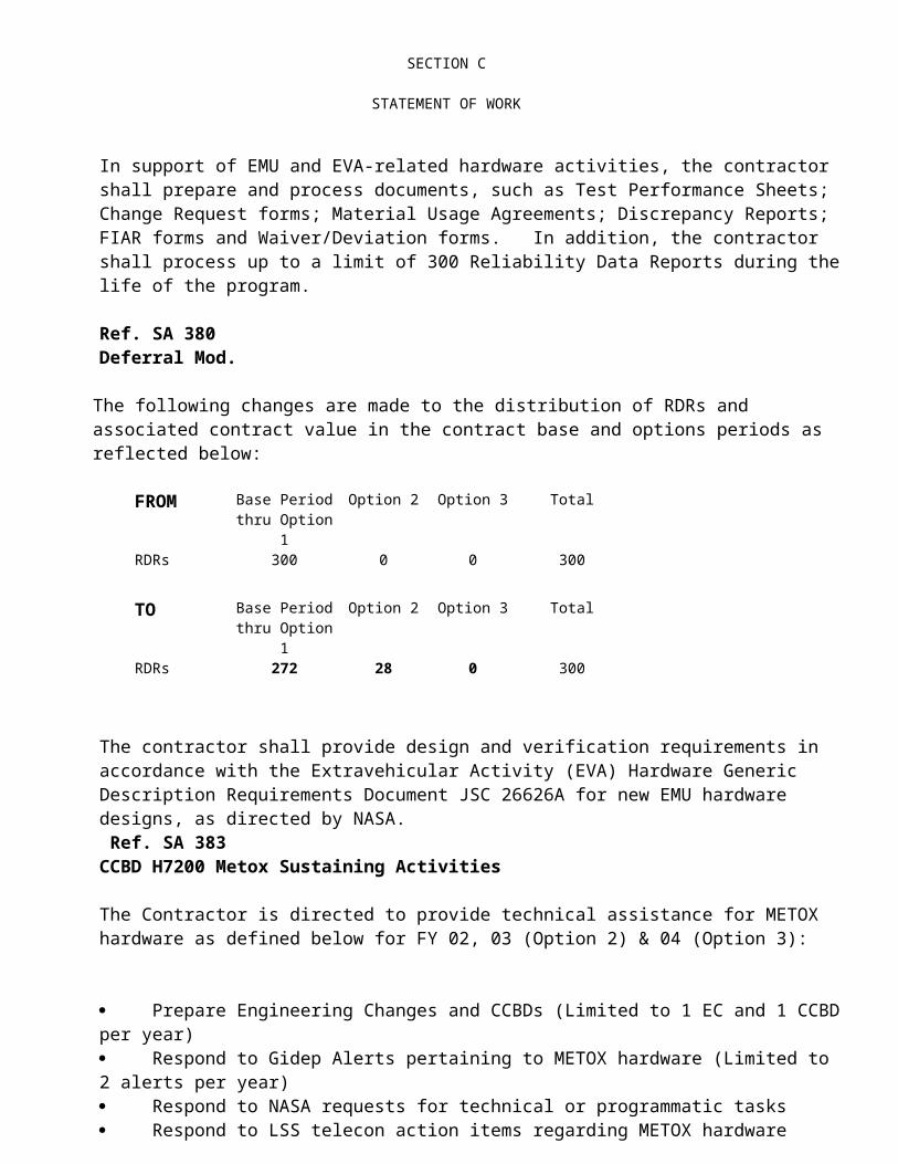
In support of EMU and EVA-related hardware activities, the contractor shall prepare and process documents, such as Test Performance Sheets; Change Request forms; Material Usage Agreements; Discrepancy Reports; FIAR forms and Waiver/Deviation forms. In addition, the contractor shall process up to a limit of 300 Reliability Data Reports during the life of the program.
Ref. SA 380Deferral Mod.
The following changes are made to the distribution of RDRs and associated contract value in the contract base and options periods as reflected below:
FROM Base Period thru Option 1
Option 2 Option 3 Total
RDRs 300 0 0 300
TO Base Period thru Option 1
Option 2 Option 3 Total
RDRs 272 28 0 300

SECTION C
STATEMENT OF WORK
The contractor shall provide design and verification requirements in accordance with the Extravehicular Activity (EVA) Hardware Generic Description Requirements Document JSC 26626A for new EMU hardware designs, as directed by NASA. Ref. SA 383CCBD H7200 Metox Sustaining Activities
The Contractor is directed to provide technical assistance for METOX hardware as defined below for FY 02, 03 (Option 2) & 04 (Option 3):
Prepare Engineering Changes and CCBDs (Limited to 1 EC and 1 CCBD per year) Respond to Gidep Alerts pertaining to METOX hardware (Limited to 2 alerts per year) Respond to NASA requests for technical or programmatic tasks Respond to LSS telecon action items regarding METOX hardware Prepare and present Program Review pitches (Limited to 1 per year) Provide Mission Support for METOX hardware Update FMEA/CIL/HAR/SAR Add METOX to the Materials obsolescence data base Add METOX to Weight Report Create/Revise cert matrix entries for EC process Add to Cert Cycle Model Add METOX to SVHS 7800, 7801, & 7802 Create and maintain METOX refurbishment schedule HSMS support for use of METOX canisters for Building 7 Chamber events (Less
regeneration of canisters) Travel to Field (Limited to 1 trip per year, 2 persons per trip, 4 days per trip)
Note: Any RDR investigations related to METOX will be considered part of the 300 RDR limit referenced in Section C of the SOW, Paragraph 2.0
2.1Systems Engineering and Integration
The contractor shall provide for the effective integration, design, and test of EMU and EVA-related hardware at the systems level. This effort shall include system level analyses and trade studies; interface definition and maintenance, including production of interface control drawings, EMU design and test requirements definition (e.g. Pre-Installation Acceptance Plan and Procedures); and system test planning, monitoring, and data evaluation. The contractor shall consider ground surveillance, maintenance and checkout activities as a part of component and systems design. As part of any detailed design activity, the contractor shall perform the system design analysis and integration required to support the development of detailed designs and that effort required to assure compatibility of component and subsystem detailed designs with the EMU system. In addition, the contractor shall insure that attention is given to crewmember activities required for EMU donning, doffing, servicing, checkout, maintenance and operations in the use (orbital) environment both IVA and EVA. The

SECTION C
STATEMENT OF WORK
contractor shall assure that the FEMU-R-001 EMU Processing and Constraints is updated to reflect all engineering changes. Reference Data Requirement Description No. 10.
The contractor shall provide technical reports which describe the studies, analyses, and results of specific engineering activities. The individual reports shall includesuch technical specialties as theoretical analyses, engineering verifications, current problems and proposed solutions, and conclusions and recommendations.
Ref. SA 112(a) The Contractor shall revise the FEMU-R-001 pages to accommodate the increased launch accelerations and increased EMU hang weight.
Certification Closure by 1/31/99
Ref. SA 189 (b) EMU Processing and Constraints Document (FEMU-R-001) Revision
The contractor shall revise the EMU Processing and Constraints Document (FEMU-R-001) to include the following post-manufacture and post-repair screening requirements:
Ref. SA 214(c) The contractor is directed to perform a risk assessment associated with expediting the present EMU preflight operations. The risk assessment will consider such items as:
Failure histories; failure mode (1/1, 2/1R, 3/1R, and 2/2) screening provided by V1103.02 and on-orbit checkout; Capability provided by the 25eva/369 day certification; Effects of landing, launch and handling without processing.
The pre-flight processing will recommend one of following scenarios 1) V1103.02 only, 2) V1103.02 with additional test or 3) No change.
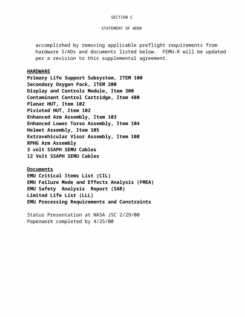
HSSSI shall present status at NASA JSC. A favorable risk assessment will result in the generation of a Level II change request recommending the implemenation of expedited EMU turnaround processing between flights. Implementation into program accomplished by removing applicable preflight requirements from hardware S/ADs and documents listed below. FEMU-R will be updated per a revision to this supplemental agreement.
HARDWAREPrimary Life Support Subsystem, ITEM 100Secondary Oxygen Pack, ITEM 200Display and Controls Module, Item 300Contaminant Control Cartridge, Item 480Planar HUT, Item 102Pivioted HUT, Item 102Enhanced Arm Assembly, Item 103Enhanced Lower Torso Assembly, Item 104

SECTION C
STATEMENT OF WORK
Helmet Assembly, Item 105Extravehicular Visor Assembly, Item 108RPHG Arm Assembly3 volt SSAPH SEMU Cables12 Volt SSAPH SEMU Cables
DocumentsEMU Critical Items List (CIL)EMU Failure Mode and Effects Analysis (FMEA)EMU Safety Analysis Report (SAR)Limited Life List (LLL)EMU Processing Requirements and Constraints
Status Presentation at NASA JSC 2/29/00Paperwork completed by 4/25/00

SECTION C
STATEMENT OF WORK
INSERT AS NEW PARAGRAPH
7.1.1.6.5 Screening for foreign metallic objects shall be perfomed by X-ray following manufacturing of multi-layer softgoods (TMG's) or repairs which expose more than the outer layer of multi-layer softgoods. Work performed on single layer softgoods, or repairs limited to the outer layer of multi-layer softgoods shall be visually screened. The visual exam shall include flexing of the item, particularly along seams. X-ray may be substitued for the visual inspection.
ADD INTO EXISTING PARAGRAPH 12.7:
The absence of foreign metallic objects must be assured. When repairing multi-layered softgoods where more than the outer layer is exposed, non-essential metallic objects shall be removed from the work site. Any pins used shall be included in a pin accounting system. Following the post-repair pin count verification, the component shall be visually screened over the entire surface. The visual exam shall included flexing of the item, particularly along seams. The visual inspection (without pin count) shall also be preformed on repairs of single layer softgoods. X-ray may be substituted for any of the pin count or visual inspection.

SECTION C
STATEMENT OF WORK
2.1.1 Interfaces
The contractor shall define EMU external interfaces with the Shuttle Orbiter, ISS systems and DTO's, payloads, and other EVA related systems which are not provided by this contract. The contractor shall provide technical information and support necessary for the preparation of Interface Control Drawings (ICD's) with interfacing systems and shall prepare and maintain ICD's with other related EVA systems. Any ICD's prepared by the contractor shall be prepared in accordance with Data Requirement Description No. 11. The contractor shall prepare and maintain the Mass Properties Report in accordance with Data Requirement Description No. 12.
The system design and performance requirements are set forth in SVHS 7800, latest revision. The contractor shall maintain a current working version of this document.
2.1.2 Hardware Development and Certification Testing
The contractor shall establish test requirements and plans, conduct PDRs and CDRs, and shall plan, perform, monitor, evaluate and report the results of development and certification. The contractor shall review test plans for tests conducted at lower levels to ensure maximum utility of the data for systems design and integration considerations. The contractor shall plan and monitor system level tests to verify EMU performance under manned, environmental, and operational conditions.
The contractor shall prepare a Certification Test Plan, Procedures, and Report and shall adhere to the certification procedures in accordance with the Data Requirement Description No. 13.
The contractor shall provide operational performance data in accordance with Data Requirement Description No. 14.
The Safety and Mission Assurance Certification Approval Request (SMACAR) form will be used for all new items Data Requirement Description No. 15.
Ref. SA 62.1.2.1. The contractor shall develop and certify the Planar HUT, long sleeve, non-ORU TMG for a total of 252 hours in accordance with a NASA approved certification plan that adheres to the requirement outlined in the Data Requirement Description No. 13. The Engineering Change Order will be approved by NASA on or before April 12, 1998. The Certification Closure date will be on or before May 1, 1998.
Ref. SA 202.1.2.2. The contractor shall revise the HUT procedures to prevent the use of "Ballnose" type hex head screw drivers during the installation or removal of the HUT PLSS and DCM captive screws. Using "Ballnose" drivers can damage the Sublimator Inlet Water Tube causing a water leak.
2.1.2..3. The contractor shall complete the certification for the mounting brackets used to install the SAAMD onto the EMU and AAP. The configuration change of the EMU and AAP
SECTION C
STATEMENT OF WORK
shall be performed per the CCCD at KSC. The contractor shall travel to KSC to support installation of the SAAMDs and brackets on the EMU and AAP for STS-90.
Ref. SA 27 2.1.2.4The contractor shall incorporate the thermal capabilities for the 4750 TMG into the 4000 Series Glove S/ADII, in accordance with the graph "4750 Glove Palm Certification Limits Radiation, Grasp, and High Pressure Grasp with and without Heating", which was developed and agreed upon by NASA, Lockheed, Hamilton Standard, and ILC (See Attachment A).Certification Closure Date: 6/15/98.
Ref. SA 29 2.1.2.5
The contractor shall certify and incorporate a new retention ring for the Planar HUT. The ring will be the same as the original production retention ring P/N SV817711 with a material change to stainless steel for increased rigidity. Thirty-two (32) pairs of retention rings will be delivered to allow retrofit of all Class I and Class III Planar HUTS. The retention rings hold the arm assemblies in position during suit doffing. In addition, they provide an interface between the crewmember and the scye bearing within the arm assembly.
Ref. SA 452.1.2.6The contractor shall replace the DCM Lens Flange (EVC) and Push-To-Talk (PTT) nameplates to accommodate the new Space to Space EMU Radio (SSER). The TMG Lens Flange patch and field modification of 9 hi-fi DCM mock-ups will also be revised.
Description Part Number Quantity Delivery Date
Push-to-Talk (PTT) Nameplates SV771739-TBD 4 7/31/98Lens Flange (EVC) Nameplates SV771729-TBD 4 7/31/98TMG Patches TBD 4 7/31/98Push-to-Talk (PTT) Nameplates SV771739-TBD 22 9/30/98Lensflag (EVC) Nameplates SV771729-TBD 22 9/30/98TMG Patches TBD 22 9/30/98
Certification Closure Date: 8/13/98
Ref. SA 502.1.2.7
The contractor shall revise the Air-Lock combination purge valve drawing as corrective action for RDR B-EMU-105-A004. This will correct the tolerance problems, which make it possible for interference to occur between the stem, spring seat, and the housing within the valve. The PDA will be modified to incorporate PIA actuation requirements.
Ref. SA 512.1.2.8

SECTION C
STATEMENT OF WORK
The contractor shall revise the micrometeoroid and orbital debris requirement in affected specifications and S/ADs for EMU to provide cumulative probability of no penetration < 0.91 for 2700 hours of EVA for a 10 year period starting with First Element Launch in the micrometeroid and orbital debris environment defined in SSP 30425. Deliverables are: specification and S/AD ECOs by 10/16/98, Flights 2A and 2A.1 system level certification analysis EMUM by 6/18/98 and full certification analysis EMUM by 10/29/98. This will provide single mission MMOD certification for ISS Assembly Flights 2A and 2A.1 and full MMOD certification for ISS Assembly flights 3A and subsequent. The contractor will update the current micrometeoroid environment from CSD-SH-028 to include the ISS micrometeoroid and orbital environment requirement contained in SSP-30425.
-----------------------------------------------------------------------------------------------------------------CR/DR: TITLE:H6817 ISS EMU MMOD CERTIFICATION-----------------------------------------------------------------------------------------------------------------
CEI Description S/AD Part II (Specification) Number
PLSS Baseline, Planar, ORU Planar SV799100/2SOP SV799045/2DCM 2000 Series SV792294/2CCC 2000 Series SV792600/2Battery SV767789/2Battery 2000 Series SV819600/2
ILC S/AD Part II (Specification) Number
HUT Pivoted 0102-10002HUT Planar 0102-110102Arm Enhanced 0103-110103Arm Enhanced/Heated 0103-110203LTA Enhanced 0104-110104Hemet 0105-10005Gloves 4000 Series 0106-19010Gloves Phase VI 0106-110106Gloves RPGH 0106-111723EVVA 0108-10008Cable SSAPH,SEMU Heated Glove 0800-111983
Ref. SA 522.1.2.9The contractor shall revise the SSA Maintenance Manual to clarify the installation and lubrication instructions for Enhanced SSA Static Seals to preclude build-up of old lubrication behind the seal lip; add requirements to the Limited Life Document to install new seals prior to each flight and restrict the operational life of installed seals to 4.5 months (137 days); and add a post-seal installation shuck test requirement to the FEMU-R-001.
Ref. SA 542.1.2.10
SECTION C
STATEMENT OF WORK
The contractor shall revise the operational shock (impact) requirement in affected specifications and S/ADs to reflect the increase in EMU/EVAs weight from 400 lbs to 725 lbs and to decrease impact velocity from 2.0 ft/sec to 1.6 ft/sec. The degree of impact protection remains unchanged from current certification. Deliverables are: Specification and S/AD ECOs by 10/16/98, Flights 2A and 2A.1 system level certification analysis EMUM by 6/18/98 and full certification analysis EMUM by 9/1/98. This effort provides single mission impact certification for ISS Assemblyu Flights 2A and 2A.1 and full certification for ISS Assembly Flights 3A and subsequent.
----------------------------------------------------------------------------------------------------------------CR/DR: TITLE:H6815 ISS EMU IMPACT CERTIFICATION
CEI Description S/AD Part II (Specification) Number
PLSS Baseline, Planar, ORU Planar SV799100/2SOP SV799045/2EEH SV767690/2CCC 2000 Series SV792600/2
ILC S/AD Part II (Specification) Number
CCA 0101-10001HUT Pivoted 0102-10002HUT Planar 0102-110102Arm Enhanced 0103-110103Arm Enhanced/Heated 0103-110203LTA Enhanced 0104-110104Helmet 0105-10005Gloves 4000 Series 0106-19010Gloves Phase VI 0106-110106Gloves RPHG 0106-111723LCVG 0107-10007EVVA 0108-10008IDB Reusable 0110-10010IDB Disposable 0110-110110Cable SSAPH, SEMU Heated Glove 0800-111983
Ref. SA 552.1.2.11 The contractor shall revise the CPPHSS document 0111-70022 to add clarification for handling polyester polyurethane bearing seals and controlled storage conditions. This clarification allows for resealing of storage bags supplied with the polyurethane seals which will keep the shelf life of the seals intact.
Ref. SA 61 2.1.2.12
SECTION C
STATEMENT OF WORK
The contractor shall update the EMU documentation to accommodate the Updated EMU Design Loads for launch and Increased Hang Weight from 285# to 310#. The following documents are to be revised:
SVHS 7800 EMU Design and Performance Requirements SpecificationsSVHS 7801 Environment Control Equipment, EMU, General MechanicalSpecification for EquipmentFMEA/CILSAR/HRFEMU-R-00127 S/ADs
Hamilton Standard (11)PLSS (I100) SV799100/2SOP (I200) SV799045/2DCM (I300) SV792294/2SCU (I400) SV767730/2EEH (I440) SV767690/2CCC (I480) SV767790/2Battery (I490) SV767892 and SV819600/2BTA (I491) SV792740/2SCOF (I495) SV799099/2AAP (I470) SV767680/2
ILC (16)CCA (I101) 0101-10001HUT (I102) 0102-10002 and 0102-110102ARMS (I103) Left and Right 0103-10003 and 0103-110103LTA (I104) 0104-10004 and 0104-110104Helmet Assembly (I105) 0105-10005Glove Assembly (I106) 0106-19010, 0106-111723 and 0106-110106LCVG (I107) 0107-10007EVVA (I108) 0108-10008IDB (I110) 0110-10010 and DIDB 0110-110110SEMU Cable 0800-111983
Delivery by October 30, 1998.
Ref. SA 622.1.2.13
The contractor shall extend certification of the Space Suit Assembly Power Harness (SSAPH) 3 Volt system. The contractor shall also update the FMEA/CIL to remove flight specific effectivities, ECO's, a Certification Report documenting the rationale for acceptability and submission of IPARS to address the electrical connector switch, electrical conductors and heater elements.
Certification Closure date by 12/31/98

SECTION C
STATEMENT OF WORK
Ref. SA 159The contractor shall extend certification of the Space Suit Assembly Power Harness (SSAPH) 3 Volt system for STS-96 through STS-104, including STS-92 and STS-93 when RPHGs are manifested.
Certification Closure by 3/26/99.
Ref. SA 64 2.1.2.14
The contractor shall incorporate an Inductor P/N SV789696-2 (which has longer electrical studs) in the External Wiring Harness P/N SV774161. The contractor shall also incorporate the new inductor into five additional I-385 O2/H2O Manifolds (S/N 006, 008, 009, 014, 015).
Certificate Closure Date by 7/30/98.
Ref. SA 67 2.1.2.15 The contractor shall integrate and certify the Space to Space Communication EMU Radio (SSER), Antenna, Cable, and Pad into the Short EMU (SEMU). The SSER components will be certified by EV and delivered directly to BAO/FEPC. SEMU level certification includes the antenna pad, installation of the SSER components on the SEMU for flight and the necessary alternations of the components by BAO/FEPC (velcro and standoffs) for proper installation on the SEMU. The documents shall be revised to include SSER nomenclature and any certification/integration impacts.
The contractor shall also fabricate 15 antenna pads (12 BAO, 2 CTSD, 1 EV). The pad will be installed in the PLSS TMG to makeup excess volume left by the older, larger antenna configuration. This pad will be tracked to the SEMU configuration level. This pad will not be required with the ORU TMG. Delivery of 4 Class 1 pads to HSMS by 7/1/98. The remaining 11 pads by 9/4/98.
Certification Closure Date by 8/13/98.
Ref. SA 69 2.1.2.16 The contractor shall perform the following effort: Manufacture the configuration 151/152 Harness Clamps and deliver as part of ORU PLSS production kits; upgrade the PLSS Mahogany Mockup and manufacture new ORU DCM Mockup for ILC Flight ORU TMG verification; New mission phase FMEA/CIL/SAR revisions incorporating ORU On-Orbit Changeout per ORU RID; Create new ORU/PLSS/DCM/Planar HUT upper and subassembly drawings to allow Boeing to track the ORU and Non-ORU PLSS, DCM, and Planar HUT Configurations, Incorporate the ORU TMG CDR RID #13 Harness alignment marks; and Create ORU MATCO database.
Certification Closure Date by 10/31/98.
The contractor shall revise the following documents to reflect the changes affected by this CCBD:
-------------------------------------------------------------------------------------------------------------

SECTION C
STATEMENT OF WORK
CD/DR: TITLE:G6615R3 EMU-ORU CONFIGURATION REVISIONS -------------------------------------------------------------------------------------------------------------
SV799100-11-00 ORU Primary Life Support SubsystemSV792294-08-00 ORU Display and Controls ModuleSVHS7801 Space Shuttle Extravehicular Mobility Unit (EMU) System, GeneralSVHS7802 Environmental Control Equipment Mobility Unit, General Mechanical SV822071 Specification For Electronic Assembly, DCMSV824131 Water Tank AssemblySV824133 Shear Plate AsemblySV767690 ORU EEHSV822066 Manifold Assembly, Oxygen, Water0111-710111 Enhanced Maintenance ManuelSV824088 Harness ClampSV799045-00 Secondary Oxygen PackSV824051 Electrical Power HarnessSV824052 Electrical Signal Harness0102-110102-03-02 Medium, ORU Planar HUT0102-110102-03-03 Large, ORU Planar HUT
Ref. SA 72 2.1.2.17 Dual Mode Relief Valves
1. The flight effectivity of Item 120 Dual Mode Relief Valve (785844-16) shall be flights STS-92, through STS-999, excluding 93, 94, 95 and 96.
2. Update Limited Life List to remove references to non-flight configurations. Perform development testing and implement a revision to the Item 120 High Mode adjustment procedure (IPT) to provide improved re-seat pressure performance.
3. Delivery: Testing and flight effectivity shall be completed by 9/30/98.
Ref. SA 71 2.1.2.18 X-Large Planar HUTThe contractor shall develop, fabricate, assemble, acceptance test, and deliver five (5) Class I and two (2) Class III X-Large Planar HUTs. The X-Large Planar HUT will have a forward positioned 16 inch Body Seal Closure and X-Large Arm opening. Certifications will be performed by analysis and similarity to the current Medium and Large Planar HUTs. Class I X-Large Planar HUTs will be manufactured in accordance with Specification/Assembly Drawing 0102-110102, and with all new hardware components. The Class III X-Large Planar HUT units shall be manufactured in accordance with HSSSI EMU Procedure 041 for Class III Builds, and by utilizing both new hardware components and Government Furnished Equipment (GFE) hardware obtained from existing Class III Pivoted HUT units. Class III HUTs are dedicated for Neutral Buoyancy Lab (NBL) use.
Delivery: X-Large Planar HUT deliveries shall be completed by September 15, 2000.
SECTION C
STATEMENT OF WORK
The first Class III X-Large Planar HUT will be delivered to NASA and the remaining Class III X-Large Planar HUT and all five (5) Class I X-Large Planar HUTs will be delivered to the United Space Alliance (USA) NAS9-20000 Contract.
Ref. SA 76
2.1.2.18The contractor shall make changes to the following documents to reflect the changes affected by the implementation of a reduction in pre-flight EMU processing. Significant features of this reduced processing approach, and how it relates to other EMU hardware activities, such as normal maintenance operations and configuration changes, are shown on Enclosure 1 "EMU Reduced Processing". The ETA chamber run, as a prerequisite for flight, is now eliminated. Enclosure 2 shows the "Flow of Major Test Assemblies". The contractor shall revise the following documents to reflect the changes affected by this CCBD as follows:
Delivery by 9/29/98
-------------------------------------------------------------------------------------------------------------------------------CD/DR: TITLE:H6863-------------------------------------------------------------------------------------------------------------------------------0101-10001 CCA0110-10010 IDBSV799100/2 PLSSSV792294/2 DCMSV799045/2 SOP
Ref. SA 78 2.1.2.19The contractor shall implement RID003 which changes the failure mode of a crewmember not able to get a drink from a 3/3 criticality to a 2/2 criticality and implement RID008 which moves the drink bag valve position from the left to the right and adjust the restraint accordingly.
The delivery schedule for the training units is revised from 7/28/98 to 4/9/99.The delivery schedule for the flight units is revised from 7/28/98 to 6/11/99.
The certification closure date is revised from 7/31/98 to 4/9/99.
Ref. SA 792.1.2.20The contractor shall extend the chronological maintenance intervals for the following SSA components to a minimum of 369 days:
HUT Shoulder Bearing Support Pivot P/N SV772302Water Line and Vent Tube Assembly P/N 0102-82437-17Water Line and Vent Tube Assembly P/N 0102-82437-18Water Line and Vent Tube Assembly P/N 0102-82437-19

SECTION C
STATEMENT OF WORK
Water Line and Vent Tube Assembly P/N 0102-82437-20Water Line and Vent Tube Assembly P/N 0102-82437-21Water Line and Vent Tube Assembly P/N 0102-82437-22Water Line and Vent Tube Assembly P/N 0102-82437-24Water Line and Vent Tube Assembly P/N 0102-82437-25Water Line and Vent Tube Assembly P/N 0102-82437-26Water Line and Vent Tube Assembly P/N 0102-82437-28Toe Cap P/N 0104-211608LCVG Vent Plenum Assembly P/N 0107-82568 (Torso Vent Duct)LCVG Restraint P/N (0107-10007, Item 0107-
82968)EVVA P/N 0108-10008-XXEVVA Sun Visor S/A P/N 24153-1 and 24143EVVA Protective Visor S/A P/N 23861-1 and 23861-2EVVA Silicone Sponge Shim Pads P/N 23292EVVA Silicone Sponge Shim Pads P/N 23304EVVA Silicone Sponge Shim Pads P/N 23305EVVA Silicone Sponge Shim Pads P/N 24330EVVA Silicone Sponge Shim Pads P/N 24331EVVA Silicone Sponge Shim Pads P/N 24332
Certification Closure date by: 11/13/98
Ref. SA 82 2.1.2.21 The contractor shall manufacture and deliver five (5) pairs of Space Suit Assembly Power Harness (SSAPH) abrasion sheath retrofit kits on or before 9/29/98 to support STS-88. USA FCE/EVA will incorporate the SSAPH abrasion sheath on the STS-88 EMUs via Type A TPS, and ECOs will incorporate the SSAPH abrasion sheath to the Remote Powered Heated Glove (RPHG) Arm Assembly.
Two Mission certification closure date by 2/11/99.
Ref. SA 882.1.2.22
The contractor shall revise the flight effectivity on the EMU SSA Planar HUT TMG from "AA/Cert Closure by 9/30/98" to "AA/Single Mission (STS-88) by 10/2/98" and "Two Mission Cert Closure by 2/11/99". The contractor shall also update the arm mobility, torque and range requirements in the Planar HUT and RPHG Arm S/ADs.
Ref. SA 89 2.1.2.23The contractor shall modify two (2) Class I (flight) LCVGs and two (2) Class III (training) LCVGs for use with the Phase VI and 4000 series gloves on STS-88. The contractor shall also fabricate four (4) pairs each of teflon cuffs and Gore-Tex thumb donning loops, which will be delivered to JSC on DR and incorporated into the LCVGs. Contractor shall prepare a Type “A” Temporary TPS and other necessary paperwork to incoporate the LCVG modifications at JSC

SECTION C
STATEMENT OF WORK
and authorizes USA to transfer the subject LCVGs to CTSD for incorporation of these modifications via TPS.
Deliverables:
Memo addressing the LCVG modifications in use with the 4000 series gloves Final Report by 10/1/98
Memo addressing the LCVG modification in use with the Phase VI gloves Final Report by 10/7/98
The above LCVG modification hardware 10/2/98
Ref. SA 902.1.2.24The contractor shall prepare the EMU Phase-2 test plan, support resolution of test requirements definition and analysis of susceptibility above lab capacity )use of HSSSI test equipment). Testing is to be conducted during the available NASA test window during the time period of October 12-23, 1998. Phase-2 quick look report due by 11/9/98. Phase-2 data analysis report due by 12/23/98.
Ref. SA 1152.1.2.26
The contractor is authorized to complete the EMU Power Harness Development & Non ORU Certification:
1. Incorporate PDR Actions; Finalize Documentation; Purchase hardware & manufacture six (6) Hi-Fi Mockup Harnesses for fitcheck & crew evaluation, and future training use
DELIVERY BY 3/8/99
2. Identify ORU TMG design changes; Fitcheck Harnesses
3. Prepare paper & hardware for CDR; Conduct CDR
4. Fabricate Certification Harnesses, Perform Certification Test & Certification Closure of Non-ORU Configuration
5. Purchase hardware and fabricate ten (10) flight Harnesses DELIVERY BY (1) 7/14/99, (4) 9/3/99 & (5) 11/1/99
Power Harness Certification Closure by 10/29/99 (Ref. SA 202)
Ref. SA 1192.1.2.27The contractor is authorized to revise the Planar HUT S/AD Part II and Enhanced PDA to increase the temperature range from 60 degrees F + 5 degrees F to 90 degrees F maximum.

SECTION C
STATEMENT OF WORK
This change is part of the corrective action for RDR I-EMU-102-A008, which documents that HUT PH017 exceeded the water circuit pressure drop requirement when PDA testing was cut short to maintain the water temperature within the spec limits. Heat from the test stand water circulation pump caused the water temperature to exceed specifications before all the trapped air was purged from the lines resulting in a high pressure drop. Additionally, the PDA will be changed to provide allowances to purge the trapped air bubbles from the circuit before measuring the pressure drop. The increased temperature range and provisions during PDA testing to purge the water lines will prevent recurrence of the failure.
Certification Closure by 3/15/99
Ref. SA 1232.1.2.28The contractor is authorized the incorporation of SV787933-5 (Mode Selector Switch Knob) to the DCM. This Mode Selector Switch Knob (SV787933-5) will have "COMM" marked lengthwise for the Space to Space EMU Radio (SSER). The TMG patch (SV771987) will have "COMM" removed for SSER flights.
Certification Closure by 2/11/99
Ref. SA 1242.1.2.29
The contractor shall revise the flight effectivity for the EMU SSAPH Abrasion Sheath Authorization from "XF:STS-88 through STS-101, excluding STS-93 and STS-95" to "XF: STS-96 and subsequent, including STS-92 when RPHG Arm Assemblies (P/N 0103-112103) are flown." The contractor shall deliver 10 pairs of SSAPH abrasion sheath retrofit kits by 2/11/99 for STS-96. Additionally, the contractor shall deliver 28 pairs of abrasion sheaths by 3/31/99 for subsequent RPHG (non-ORU) flights. Delivery of the 38 pairs total of sheaths includes 30 pairs to USA to support flight andn training and 8 pairs to CTSD for chamber support.
Certification Closure by 2/11/99

SECTION C
STATEMENT OF WORK
Ref. SA 1262.1.2.30
The contractor is authorized to modify the Waist TMG pattern and the zipper on the Waist Restraint to resolve the tight fit of the Waist TMG caused by the larger Adjustable Brackets. Changes are also necessary, to the bracket housings, in order to make the two sleeves a common length.
Certification Closure by 9/2/99 (for STS-97 (4A) with Full Certification Closure by 11/3/99
Ref. SA 1302.1.2.31
The contractor is authorized to incorporate an alternate DCM Mode Selector Switch (SV826125-1) in order to provide sufficient inventory of DCM switches. The original DCM Rotary Switch design from previous supplier Armtec Industries is being replaced with a switch manufactured by Applied Resources Corporation. The design is based on a previously certified Shuttle Switch ME 452-0093. Changes to that design include replacement of Nitrile O-rings with EPR and nylon bushings with Rulon, which complies with present EMU requirements. The DCM S/AD shall also be modified to allow the increase in contact resistance from 30 milliohms to 60 millohms to meet current vendor requirements.
Certification closure by 9/30/99.
Ref. SA 1312.1.2.32
The contractor is authorized to incorporate an alternate Push to Talk Switch (SV767794-2), FAN/CLIV Switch (SV771887-3), Feedwater Switch (SV767795-3), and the Caution Warning System Switch (SV767792-2) for the DCM that will provide sufficient inventory of DCM switches. The original DCM toggle switch design from previous supplier, Armtec Industries was bought by Applied Resources Corporation (ARC). The Armtec Industried design has been maintained in the ARC designs. The DCM S/AD shall also be modified to allow the increase in contact resistance from 30 milliohms to 60 milliohms to meet current vendor requirements. Vibration, leakage, and temperature certification test shall also be performed. SVHS7818, SVHS7816, SVHS7810, and SVHS7815 (procurement specifications) will be combined and replaced by SVHS148542 due to their similarity.
Certification closure by 9/30/99.
Ref. SA 164In order to procure tha alternate DCM toggle switches to the latest specification, the procurement specification SVHS7815 shall be replaced with SVHS 10114.
Certification closure by 9/30/99.
Ref. SA 1342.1.2.33
SECTION C
STATEMENT OF WORK
The contractor is authorized to certify, implement, and fabricate the static seals used in the Enhanced Sizing Rings, Fabric Attachment Rings, Arm Bearings, and associated test fixtures. The initial seal requirement is for STS-98 (5A) with a delivery date of 11/05/99 for flight seals. Seal quantities are as follows, which includes seals for test fixtures: This meets the requirement to outfit the USC (FCE) EMU processor with the initial lay-in of inventory as follows:
Initial Due to STS–102 Seals STS-100 Seals Balance to Balance to Balance to FCE-EVA to FCE-EVA to FCE-EVA FCE-EVA CTSD ILC Dover Total11/05/99 by 12/17/99 by 01/21/00 by 2/28/00 by 2/28/00 by 2/28/00 Qty.
Arm (ref. 25570) 20 each 12 each 12 each 66 each 16 each 14 each 140 eachThigh (ref. 25410) 20 each 12 each 12 each 82 each 24 each 10 each 160 eachBoot (ref. 25417) 20 each 12 each 12 each 200 each 32 each 14 each 290 each
(Ref. SA 140)2.1.2.34
The contractor is directed to incorporate screw length changes at three locations, total, in the leg and boot assemblies as well as the incorporation of thicker washers in four locations.
Bracket Screw FROM: TO:Location Current Screw Current Washer Proposed Screw Proposed Washer
Upper Leg Inner NAS1101E06-10 N/A no change required N/AOuter NAS1101E06-10 N/A NAS1101E06-9 N/A
Lower Leg Inner NAS1101E04-10 NAS620C4L NAS1101E04-11 NAS620C4Outer NAS1101E04-10 NAS620C4L no change required NAS620C4
Upper Boot Inner NAS1101E04-12 NAS620C4L NAS1101E04-11 NAS620C4Outer NAS1101E04-10 NAS620CAL no change required NAS620C4
Also the contractor is directed to incorporate this change by temporary Type A TPS and use in manned ground operations in advance of the released ECO, Mod Kit, or certification closure. Approval of ECO’s and certification closure will occur prior to the STS-96 EVA FRR (currently scheduled for 4/22/99). The incorporation of this change will result in the following Part No. changes:
From: To:Enhanced Boot AssemblyLarge (old bladder cloth) 0104-210895-09/10 0104-210895-17/18Small (old bladder cloth) 0104-210895-11/12 0104-210895-19/20Large (new bladder cloth) 0104-210895-13/14 0104-210895-21/22Small (new bladder cloth) 0104-210895-15/16 0104-210895-23/24
Enhanced Leg Assembly(old bladder cloth) 0104-210575-03 0104-210575-05(new bladder cloth) 0104-210575-04 0104-210575-06
The following is the delivery schedule for washers and screws:
Previously Delivered to JSC
Quantity Needed for STS-96
Quantity Needed for STS-93
Balance to FCE-EVA by 5/28/99
Quantity to CTSD by 5/28/99
Quantity to ILC Dover by 5/28/99
TOTAL
NAS620C4, Washer 64* 192 96 1462 250 100 2100

SECTION C
STATEMENT OF WORK
NAS1101E06-09,Screw 164 32 16 452 100 100 700NAS1101E04-00,Screw 164 64 32 804 100 100 1100
*The balance of the 224 Washers needed for STS-96 and STS-93 to be delivered by 3/22/99.
Certification Closure Date by 4/20/99.
(Ref. SA 143)2.1.2. 35
The contractor is directed to modify the Maintenance Manuals to revise the torque values by incorporating the findings as shown in Attachment I.
(Ref. SA 144)2.1.2.36
The contractor is directed to replace twenty-five (25) Multiple Connector screws and increase the torque value of the installed screws as directed in the attached Table 1. The current 300 series stainless steel screws yield a strength of 25 ksi minimum and will be replaced with A286 screws which yield a strength of 107 ksi minimum. The status of the Multiple Connectors is located in the attached Table 2.
(Ref. SA 147)2.1.2.37
The contractor is directed to implement the GSFC HST requirements for thermal vacuum bake-out for seven (7) pairs of EMU Glove TMGs for use on Hubble Mission HST03A. Of these, three (3) pairs of configuration 0106-211768 TMGs will be sent to ILC Dover by 4/16/99 for removal of heaters, shipped to JSC for thermal vacuum bake-out and returned to ILC Dover by 5/28/99 for re-installation of heaters. The other four (4) pairs must first be exposed to thermal vacuum bake-out at JSC prior to being sent to ILC Dover by 4/30/99 for modification. These four (4) pairs of TMGs are also authorized to be modified for use on Hubble Mission HST03A as follows: Three (3) pairs of configuration 0106-811211 TMGs and one (1) pair of configuration 0106-811852 TMGs will be modified to the approved 0106-211768 configuration. The contractor shall also modify one (1) additional pair of glove TMGs from configuration 0106-811211 to 0106-211768, this pair will be sent to ILC Dover by 4/16/99. This particular pair of TMGs does not require bake-out.
Delivery date shall be by 7/2/99.
(Ref. SA 151)2.1.2.39
Due to material obsolescence, the contractor shall change the terminal plate from aluminum to epoxy fiberglass in the Volume Control Potentiometer (SV767784-2) and the Display Intensity

SECTION C
STATEMENT OF WORK
Control Potentiometer (SV767785-2) for the DCM, which will provide sufficient inventory of the DCM Potentiometers.
Certification Closure by 9/30/99.
Ref. SA 199The contractor is directed to utilize the Waiver WVR 10880 in Attachment A. This waiver allows the use of DCM Potentiometers SV767784-2 (I-360) and SV767785-2 (I-361) that do not meet the requirements of NHB5300.4. This waiver allows the use of acid based flux, excess wire turns around the turrets, and excessive clearance between insulation and turret.
Ref. SA 1542.1.2.40
The Contractor shall incorporate new DCM Nameplates
Description Part Number Quantity Delivery Date
Caution Warning System Nameplate SV771741-4 26 each 10/15/99*Push-to-talk Nameplates SV771739-3 26 each 10/15/99*
The changes accommodate the functions of the Space to Space EMU Radio (SSER) and Caution Warning System (CWS).
Certification Closure date by 8/29/99*nameplates will be provided to the field to support STS-92 and subsequent flights
Ref. SA 156
2.1.2.41
ITEM Requirement Microswitch Add to the Limited Life List for P/N SV771842 replacement after 15 years of
service as a component of the Vent Flow Sensor.
PLSS S/AD & FEMU-R-001 PIA insulation resistance test shall for the Check Valve/Vent be added. A Service Instructions will be provided for Flow Sensor, P/N SV771836 this test. Every 2 years this test will be
Performed at USA.
Vent Flow Sensors Acceptable for flight use with S/Ns 003, 004, 007, the recommended 2 year I.R. 008, 009, &019 inspection
Ref. SA 1582.1.2.42

SECTION C
STATEMENT OF WORK
The contractor is directed to remove the Limited Life constraint on the LCVG that requires a preflight inspection of the cuff.
Certification Closure Date by 11/4/99
Ref. SA 1572.1.2.43
The certification dates for the following documents shall be extended to accommodate the ORU, Advanced Battery, and Metox integration which will be certified with the ORU TMG that incorporates the Power Harness:
ORU Certification EMUM by 4/27/00ORU EC/ECO Certification, to support STS-100 (6A), by 3/29/00 Appendix A SVHS7800 Certification EMUM by 5/25/00Appendix A SVHS7800 EC, to support STS-104 (7A), by 4/26/00
Ref. SA 1672.1.2.44
The contractor shall perform the material compatibility testing and evaluation necessary to certify the use of antimicrobial coating TCHDE for Space Station activities.
Certification Closure by 1/11/00
Ref. SA 1702.1.2.45
The contractor shall perform the following activities on the Phase VI Glove restraint for the redesign and full certification as follows: (1) Perform Non-recurring and testing activities (including one 458 hour DVT) associated with the implementation of corrective action to RDR J-EMU-106--019 by implementing edgelock, pleat redesign, and knuckle easement changes; (2) implementation of additional modifications beyond corrective action required for RDR J-EMU-106--019 by changing the certification test requirement from 50 EVA certification to 25 EVA certification, developing a post EVA TMG inspection procedure for use on-orbit, changing the certification cycle test profile, changing the palm bar strap attachment, changing the middle secondaries, creating a new certification test plan, and incorporating new bladder cloth in the Glove Flange; (3) retrofit the existing Gloves; (4) conduct a delta CDR; (5) restart the one certification test program from the beginning; and (6) allow 63 hour certification.
63 Hour Certification Closure by 9/28/9925 EVA Certification Closure by 12/22/99
Ref. SA 198The contractor shall perform the following activities on the Phase VI Glove for the redesign and full certification as follows:

SECTION C
STATEMENT OF WORK
1. Install teflon liner into bladder, flocking of bladder to flange, and turn restraint flange seam allowance away from bladder.
2. Revise the whipstitching method used for ORU bracket attachment, apply a second coat of edgelocking to three high wear seams, transition of index finger base panel seam allowance from 5/32" to 7/32", and revise manufacturing process to improve bladder anchor tape bond strength consistency.
2. Retrofit of existing gloves to incorporate design changes.3. Modify the Predelivery Delivery Acceptance document to remove Manned Pressurized
Time from gloves upon delivery and to exclude TMGs from break-in cycling.4. Modify Acceptance Data Package to document that the six-hour break-in requirement is
satisfied prior to delivery and the start of Manned Pressurized Time tracking.
Ref. SA 1712.1.2.46
The contractor shall modify one pair of 4750 TMGs (S/N 083) from the 0106-811211-01/02 configuration to the 0106-211768-05/0-6 configuration.
Delivery date, to meet STS-92, by 12/16/99
Ref. SA 177 & R12.1.2.47
The contractor shall newly design screw and nut , use as part of the mounting of the Lower Relief Valve Tube (LRVT), to the Item 115 Shear Plate. The LRVT has a slotted tab that is attached to the Shear Plate, by means of a screw and nut, with a standard NAS620 washer. The washer is not large enough to fully capture the tab in all conditions, which can allow the tab to slip out from under the washer due to handling from installation and removal of the SOP from the Shear Plate. This condition was documented in RDR B-EMU-115-A004. An oversized washer will be incorporated to ensure that the tab is fully captured.
Certification closure by 12/23/99.
Delivery of 25 flight screw and nut kits shall be by 2/16/00.
Ref. SA 1782.1.2.48
The contractor shall modify the Baseline Maintenance Manual 0111-70024 and the EMU system level certification memorandum to include the acceptable alternate valsalva devices, which will be provided by Avitar Technologies.
Ref. SA 1802.1.2.49

SECTION C
STATEMENT OF WORK
The contractor shall produce and delivery the following EMU Power Harness configurations as follows:
Delivery Cum Totals L-90 L-270SEMU HARNESSES Dates (By Date) Flight Req’mt Req’mt
Mfg 5 SEMU Harnesses 11/26/99 5 SEMU 4A 12/24/99 6/28/99*Mfg 4 SEMU Harnesses 1/20/00 9 SEMU 5A 1/21/00 7/26/99*Mfg 11 SEMU Harnesses 3/30/00 20 SEMU 5A.1 3/31/00 10/2/99*Mfg 11 SEMU Harnesses 6/5/00 31 SEMU 6A 4/28/00 10/31/99*Mfg 3 SEMU Harnesses 7/25/00 34 SEMU 7A 5/24/00 11/28/99
LAA HARNESSES
Mfg 5 LAA(pr) Harnesses 11/26/99 5 LAA 4A 12/24/99 6/28/99*Mfg 4 LAA(pr) Harnesses 1/20/00 9 LAA 5A 1/21/00 7/26/99*Mfg 3 LAA(pr) Harnesses 3/30/00 12 LAA 5A.1 3/31/00 10/2/99*Mfg 8 LAA(pr) Harnesses 4/14/00 20 LAAMfg 11 LAA(pr) Harnesses 7/30/00 31 LAA 6A 4/28/00 10/31/99*Mfg 11 LAA(pr) Harnesses 9/19/00 42 LAA 7A 5/24/00 11/28/99Mfg 11 LAA(pr) Harnesses 11/1/00 53 LAA 7A.1 8/30/00 3/3/00Mfg 11 LAA(pr) Harnesses 12/18/00 64 LAAMfg 11 LAA(pr) Harnesses 1/30/01 75 LAA 8A 12/29/00 7/2/00Mfg 11 LAA(pr) Harnesses 3/12/01 86 LAAMfg 11 LAA(pr) Harnesses 4/16/01 97 LAA
EMU POWER HARNESSES
Mfg 6 EMU Power Harnesses** ***3/8/99 6 EMU PHDELETED PER SA 227Mfg 4 EMU Power Harnesses** ***11/29/99 10 EMU PH 4A 12/24/99 6/28/99
(Ref. SA 202)Mfg 5 EMU Power Harnesses** ***12/30/99 15 EMU PH 5A 1/21/00 7/26/99
(Ref. SA 202)Mfg 3 EMU Power Harnesses 2/11/00 18 EMU PH 5A.1 3/31/00 10/2/99Mfg 3 EMU Power Harnesses 3/24/00 21 EMU PH 6A 4/28/00 10/31/99Mfg 3 EMU Power Harnesses 5/5/00 24 EMU PH 7A 5/24/00 11/28/99Mfg 2 EMU Power Harnesses 6/2/00 26 EMU PH 7A.1 8/30/00 3/3/00
Ref. SA 227Description (PN SHG13101723-302) QTY Delivery
Date
Class I Certification EMU Power Harness for CTSD 1 2/28/00*Class I EMU Power Harness for USA 4 2/28/00**Class I EMU Power Harness for USA 5 2/8/00Class III EMU Power Harness for HSWL/CTSD 1 2/11/00for the High Fidelity ORU MockupClass I EMU Power Harness for USA 2 2/11/00

SECTION C
STATEMENT OF WORK
Class I EMU Power Harness for CTSD 1 3/24/00Class III EMU Power Harness for USA 2 3/24/00Class I EMU Power Harness for USA 3 5/5/00Class I EMU Power Harness for USA 2 6/2/00
*Certification Unit previously built as SHG13101723-301 This item will be reconfigured and completed as SHG13101723-302 per the date above.
**Previously delivered as SHG13101723-301 These Items will be reconfigured and redelivered as SHG13101723-302 per the delivery dates above.
*4A, 5A, 5A.1 & 6A Six (6) Training SEMU & LAA (pr) Harnesses, CTSD modified 3-Volt configurations and supplied to USA** Nine (9) Flight and six (6) Training EMU Power Harnesses mfg’d under Base CCBD***4A, 5A, & 5A.1 Delivery Dates from Base CCBD
Ref. SA 1822.1.2.50
The contractor shall revise the Planar HUT S/AD Part 1 and Enhanced Maintenance Manual to create a new configuration that changes the installation procedure for the retention ring screw to prevent galling and breakage of the screw. Revisions to the documents include requirements for adding Krytox lubricant to the threads, controlling the running torque, lowering the final torque, and providing a procedure to lower the running torque if it is above specification. Also correct Retention Ring Screw part number typographical error and erroneous callout for thread lock compound and primer in the Enhanced Maintenance Manual and S/AD part 1.
Certification Closure by 10/29/99
Ref. SA 2002.1.2.51
The contractor shall certify and incorporate clear Krylon for use as an acceptable alternate topcoat on removable SSA component labels. The above change requires updates to the Enhanced Maintenance Manual (0111-710111), Baseline Maintenance Manual (0111-70024) and the Material Data Sheets. Acceptability for use Memo will be submitted by 10/15/99 to address flights that launch prior to the scheduled approval of the EC.
Certification by 1/31/00
SECTION C
STATEMENT OF WORK
(Ref. SA 205)2.1.2.52 Certification of Manufacturing Process Containers and Implementing of EMU SSA Visor Storage
The Contractor is directed to identify and certify an alternate storage container, process a Class I ECO to the CPPHSS to implement the change, and provide certification for the existing manufacturing process containers (P/N 10254) for use as an approved shipping container. Also, the Contractor is authorized for future inventories of visors to be stored in alternate storage containers on DR until alternate visor storage containers are certified.
Certification closure by 3/7/00
(Ref. SA 208)2.1.2.53 EMU SSA IDB TEAR CORRECTIVE ACTION
The Contractor is directed to revise the the Maintenance Manual as follows:
1. Revise the Quadrennial Inspection Procedure listed in the Maintenance Manual from reactivating the adhesive with MEK to reactivate velcro adhesive using urethane adhesive, UR1087.
2. Add a provision to the Maintenance Manual to re-apply primer if the primer/adhesive totally debonds from the fastner tape.
The Quadrennial Inspection and internal Work Instruction procedures will be revised to include cautionary notes to advise of the adverse effects of MEK on the IDB bladder material. Also, the Contractor is directed to revise the FEMU-R-001 (EMU Processing and Constraints Document) to incorporate new procedures to include increased inspections of IDBs prior to flight.
(Ref. SA 216)2.1.2.54 REDESIGN INLET FILTER FOR ITEM 146
The Contractor is directed to redesign Item 146 Inlet Filter to incorporate a filter size of 25-micron (0.001") max in place of the existing 141-micron filter. Also the Contractor shall deliver eighteen (18) new 25-micron max filters on or before 7/19/00. These filters will be used to retrofit the Item 146 fleet (which will be performed by USA).
Ref.: SA 348H6975R1 EMU LSS Redesign Inlet Filter For Item 146
The contractor is directed to delete the Incorporation of the 25-micron filter into the Item 146 Positive Pressure Relief Valve.
(Ref. SA 220)2.1.2.55 EMU SSA CPV BINDING CORRECTIVE ACTION

SECTION C
STATEMENT OF WORK
The Contractor is directed to process a Class I ECO to the Maintenance Manual (0111-70024) to add a step which re-applies lubrication to the sliding surfaces of the CPV.
Ref. SA 2232.1.2.56 EMU SSA MULTIPLE WATER CONNECTOR (MWC) 369 DAY SERVICE
INTERVAL
The Contractor is directed to certify and implement a revision to the Hard Upper Torso (HUT) and Liquid Cooling and Ventilation Garment (LCVG) service/replacement descriptions in the Limited Life Items List (LLIL) from "once every 6 months and prior to each flight" to "Prior to each flight and 369 days". In addition, the contractor shall create a flight procedure to supply a functional work-around in the event the HUT Multiple Water Connector experiences leakage when de-mated. Additionally, the contractor shall (1) revise Multiple Water Connector Cover ("Jumper Loop"), P/N 0102-89931, usage to allow it to be flown as a separate item for contingency use and (2) revise existing HUT and LCVG Limited Life Items List references from 370 days to 369 days to match current ISS requirements.
Certification by 3/23/00
As a result of the above change the contractor is directed to revise the following documents:
FMEA/CILS/ADOperations and Maintenance Instructions (OMI)Limited Life Items List, EMU1-19-001
Ref. SA 2262.1.2.57 ADDITION OF A LIGHTS AND CAMERA WEIGHT LIMIT TO THE HELMET/EVVA
INTERFACE CONTROL DOCUMENT (ICD)
The Contractor is directed to add a 20-lb maximum weight limit, Center of Gravity and engagement force limit to ICD-HSD-4-0002-01-6 to incorporate the new Lights and Camera Assembly. In addition, the Contractor shall provide a certification by analysis addressing the Light and Camera to Helmet/EVVA interface. Also, the Contractor is directed to add requirements to the FEMU-R-001 to minimize the effects of 1G evaluations on the Helmet/EVVA Assembly.
Certification by analysis memo by 4/10/00 As a result of the above change the contractor is directed to revise the following documents:
S/AD Part II 0108-10008FEMU-R-001ICD-HSD-4-0002-01-6

SECTION C
STATEMENT OF WORK
Ref. SA 2342.1.2.58 EMU-LSS: Revise Post Cure on I-146 Positive Pressure Relief Valve Poppet Seal and Perform Certification
The Contractor is directed to incorporate a revised cure for the I-146 Positive Pressure Relief Valve Poppet Seal (1hour @ 250 degrees F/1 hour at 300 F/1 hour @350F and 16 hours @400F). The valve assembly will see 7 days @ 150 degrees F thermal conditioning prior to acceptance test. Thermal conditioning will minimize the amount of compression set that will occur over the service life of the relief valve after it is delivered for flight service. To satisfy 369 days certification of this new configuration one flight valve will be subjected to 24 days @ 150 degrees F and then run through a full acceptance test. These changes will only apply to SV787036-10 and subsequent configuration valves. Item 146, S/N 146 has been delivered on PLSS 1018 as a -10 configuration, however, all the above changes were incorporated. It will be re-identified per Service Instruction SI-EMU1-437.
The Contractor will also perform the following to all Item 146 Positive Pressure Relief Valves prior to shipment:
1. Removal of the inlet screen and visually inspect upstream side of poppet seal for contamination. Clean valve if required.
2. Perform crack/flow/reseat verification testing.
Deliverables:
Description QTY Delivery Date
Positive Pressure Relief Valves (SV787036) 6 5/9/003 6/1/003 7/5/002 8/2/00
Ref. SA 2402.1.2.59
The Contractor is directed to perform the following activities:
a. Add the DCM Multiple Connector to the Limited Life List. The Limited Life List shall include an inspection and cleaning operations that will be performed by USA every four years.
b. The following are deliverables (Table 1) to support replacement hardware in the 7 DCMs (in Table 2 below):
Table 1Part Name & P/N Qty Delivery date CommentsMultiple Connector BasesP/N 22486
5 12/21/00 These will support replacement of 5 bases if required during disassembly/inspection procedures
Water Poppets 10 12/21/00 2 water poppets per assembly to be replaced as required during disassembly/inspection procedures
Filters P/N 24162 7 8/3/00 1 filter per assembly to be replaced as required during disassembly/inspection procedures

SECTION C
STATEMENT OF WORK
O'seals P/Ns 6102-1, 6108-1, 6110-1, 6017-1
56 (8 per base)
8/3/00 O'seals to be replaced as required during disassembly/inspection procedures
Inspection / Cleaning Procedure
1 7/27/00 Service Instruction SI-EMU-424 will perform inspection/ cleaning procedures
c. Develop inspection / cleaning criteria by evaluating non-flight multiple connector hardware for contamination. Service Instruction SI-EMU-424 will provide direction to implement the refurbishment at scheduled maintenance when hardware/documentation is available. The table below will take precedence over the Limited Life List requirements for the following seven multiple connectors.
Table 2 DCM Multiple Connector I-330 S/N
M/C Birth Date
Manifold S/N
Est. Refurbishment Date
Refurbishment will be performed by USA (Location)
162 2/25/94 014 1/01 USA / JSC164 2/11/94 015 1/01 USA / JSC166 3/14/94 008 1/01 USA / JSC167 9/1/94 006 1/01 USA / JSC169 9/1/94 009 1/01 USA / JSC172 3/23/98 003 1/01 USA / JSC177 5/6/98 007 1/01 USA / JSC

SECTION C
STATEMENT OF WORK
Ref. SA 2372.1.2.60 EMU SSA Flight Cover Multiple Water Connector (FCMWC) Pin Fall-Out
The Contractor is directed to provide documentation for the removal of pins from the Three Hose Clamp on all FCMWCs. The removal of pins will be performed by USA or CTSD. The FCMWCs will be reidentified to a new part number (0102-89931). The following items will be updated to include the new configuration:
Baseline Maintenance Manual, 0111-70024Enhanced Maintenance Manual, 0111-710111S/AD Part 1 for the Pivoted and Planar HUT
A Modification Kit (paper only / hardware not applicable) will be created to perform the pin removal at JSC by 10/02/00.
Certification by 9/12/00
Ref.SA 2452.1.2.62 Certification of ISS Barcode labels for Metox & EMU Softgoods
The contractor is authorized to perform the following tasks in order to define the ISS barcode label requirements for Metox and EMU softgoods:
a. Procure & test barcode labels from Metalphoto to determine their suitability for use with the Metox Canister
b. Assess the impacts of barcode labels on the EMUc. Certify (by Analysis) a barcode for use with EMU softgoods and Metox Canisterd. Generate installation procedures with location imagese. Generate FEMU-R-001 changes to implement barcode labels for flight and training H/W
(Rev 1 to this CCBD will incorporate the FEMU-R changes)f. Update the S/ADs to acknowledge the presence of EMU barcode labels
The deliverables are as follows:
Description: Quantity: Delivery to USA by :
Class I XHT Barcode Labels 150 each October 20, 2000Class III XHT Barcode Labels 25 each October 20, 2000
As a result of the above changes, the contractor is directed to revise the following documents:
S/AD(Specification Assembly Drawing)FEMU-R updates will be provided with revision one of the CCBD.
Certification date by October 19, 2000.
Ref. SA 2462.1.2.63 EMU Servicing Kit Design, Fabrication and Certification

SECTION C
STATEMENT OF WORK
The contractor is authorized to design an EMU Servicing Kit that incorporates the existing EMU Maintenance, Preparation, Biomed Kit's supplies with additional quantities of the supplies to support the 12 EVA requirement for International Space Station (ISS). In addition to the quantities referenced below, the contractor is required to certify both, the Servicing Kit and its contents, for use onboard the shuttle and ISS.
The deliverables are as follows:
Description: Quantity: Delivery Date Due:
Prototype(To support 5A.1 Crew) 1 12 Jun. 2000Servicing Kits Class III 3 23 Aug. 2000Servicing Kits Class I 8 15 Nov. 2000
As a result of the above change the contractor is directed to revise the following documents:
S/AD(Specification Assembly Drawing)SEG DrawingFEMU-R-001 updates will be provided with revision one of the CCBD.
Certification date is September 7, 2000.
Ref. SA 315 &Ref. CCO 236
EMU Small Planar HUT, Small Arms, Canted Waist, Extra Small Short LCVG, BSI & EVVA & Upper Arms & Small Arm Bearing
The contractor shall complete the following HUT development activities:
a. Complete Small Planar HUT Preliminary CATIA foam model design and structural design analysisb. Create and deliver a preliminary requirements document by 3/15/00c. Generate a Small Planar HUT certification matrix d. Conduct a Preliminary Design Review (PDR) of the Small HUT at JSC by 5/31/00e. Complete Small EMU Preliminary design of the canted waist, extra small short LCVG, BSI and
EVVA Knob.f. Create and deliver a preliminary requirements document by 5/25/00g. Generate a small arm, canted waist, extra small short LCVG, BSI and EVVA certification matrix h. Conduct a Preliminary Design Review (PDR) of the Small EMU Hardware at JSC by 5/25/00i. Deliver five (5) pairs of Prototype Lower Arms (P/N TBD) by 4/30/00j. Complete Small EMU Preliminary design of the upper arm, small arm bearing and small arm.k. Create and deliver a preliminary requirements document by 7/27/00l. Generate an upper arm, small arm bearing and small arm certification matrix m. Conduct a Preliminary Design Review (PDR) of the upper arm, small arm bearing, and
small arm at JSC by 7/27/00n. Deliver three (3) pairs of Prototype Upper Arms (P/N TBD) by 4/30/00o. Perform task board fitchecks at JSC to evaluate the three (3) pairs of upper arms

SECTION C
STATEMENT OF WORK
The contractor shall also modify two (2) pairs previously manufactured prototype upper arms to implement changes from field evaluation results of the Torroidal & Wedge Designs, and fabricate one (1) pair of shortened Hybrid Arms. “
Ref. CCO 294Small EMU SSA Development and Certification Program
The contractor is directed to initiate the detail design and analysis of Upper and Lower Arms, Canted Waist, LCVG, intermediate size boot sizing insert and EVVA Visor knobs. Fabricate Development and Test (DVT) components, which are built to a higher standard than the prototypes and incorporating any changes identified during manufacturing. DVT components are then used to do development testing to establish the life of the component and ensure that the flight hardware will meet certification requirements. Support 1-g crew fitchecks. Support Neutral Buoyancy Lab (NBL) runs with DVT gear and with the first set of training hardware. Generate and conduct CDR, including RID review and closure. Fabricate Certification components and conduct cycle certification of Upper and Lower Arms, Small Arm Bearing, and Canted Waist. Prepare production documentation, produce one set of each component (to be used for training), support SMART review, define standard inspection criteria for new bladder and issue man-rating memo for NBL Runs.
Ref. CCO 295Small HUT Development
The contractor is directed to initiate the Small Planar HUT CATIA design; Structural/Design Analysis; Fabricate HTS foams: Upgrade Prototype HUT; Complete Small HUT TMG Design; Conduct CDR; Complete Class III Drawings; Manufacture Ext/Int HUT SLAs; Design & fabricate HUT Tubes/Ducts/Shields/Covers & Tooling; Complete Class I drawings; Manufacture 1st Class III HUT; and complete certification.
Per SA 256:2.1.2.65: EMU LSS and SSA MPLM Stowage of IEU and Select SSA Items
The contractor is directed to review, evaluate and certify that the following list of equipment are acceptable for being stowed and launched within the Multi-Purpose Logistics Module (MPLM). The following components shall be certified to the requirements stated on pages 7-15 of this supplemental agreement.
*Table 1: Part Number:
1. Umbilical, EMU ISS SV819500/2 (dry only)2. Arm Assembly 0103-1101033. Lower Torso Assembly 0104-1101044. LTA Donning Handles AL9857 & AL98585. Disposable In-Suit Drink Bag 0110-110110 (dry only)6. Boot Sizing Inserts 0104-2120807. Phase VI Gloves 0106-1101068. CCA 0101-100019. Adjustable Thermal Mittens 0106-811540

SECTION C
STATEMENT OF WORK
10.LCVG 0107-10007 (dry only)11.Arm and Leg Sizing Ring Kits SJD13101714 & SJD1310171612.HUT MWC Jumper Loop 0102-89931 (dry only)13.Thermal Slippers 0107-81182014.Maximum Absorbency Garment SED1310172015.Comfort Gloves 0106-8490616.Spectra Comfort Gloves ST91G304517.Sock Liners ST17C3309
*NOTES: - The vacuum requirement for MPLM will not be addressed for offgassing and; therefore, no testing at White Sands is required for this condition.
- If the MPLM is depressurized, the components are no longer required to function. The contractor shall identify the minimum acceptable pressure necessary for the components to function.
- The packaging requirements for each equipment piece will not be defined by this Supplemental Agreement. The packaging provides an environment barrier, including cushioning materials or devices that adequately protects the items from damage and will not present a decompression hazard. These items will be packaged for the return trip.
If certification is not possible for a specific component, written justification shall be provided that details the reason(s) that prevent such qualification. The contractor is further directed to update the following documents and specifications accordingly:
1. S/AD Part II2. Arm (0103-110103)3. LCVG (0107-10007)4. Lower Torso Assembly (0104-110104)5. Disposable In-Suit Drink Bag (0110-110110)6. Planar HUT (Jumper Loop) (0102-110102)7. Pivoted HUT (Jumper Loop) (0102-10002)8. Phase VI Glove (0106-110106)9. CCA (0101-10001)10. SVHS780011. Limited Life List EMU-19-001A
Certification Date by November 21, 2000.
Per SA 257:2.1.2.66 EMU Delta Certification / Evaluation for ISS Requirements
The contractor is hereby directed to certify and incorporate the following Engineering Change Orders (ECO) and On-Orbit Replaceable Unit (ORU) Requirements into the respective documents:
ECO Number: Component Name: Affected Document:

SECTION C
STATEMENT OF WORK
ECO 991-0147 RPHG Arm Assembly S/AD 0103-112103
ECO 991-0151 Phase VI Gloves S/AD 0106-110106
ECO 991-0155 EMUPH SEMU 12V Harness S/AD 0800-112418
*On-Orbit Replaceable Unit Requirements:
1. The EMU shall be capable of being disassembled and reassembled on-orbit to allow replacement of designated ORUs.
2. The EMU Space Suit Assembly (SSA) shall accommodate on-orbit resizing.
(*Note: The document affected by the above two ORU requirements is SVHS7800.)
2.1.2.67Ref.: SA 275
The contractor is hereby directed to update the S/AD to reflect the new Fresnel Lens configuration. Actions to be completed with this tasking are as follows:
a. Generate and submit an ECO to update the Helmet S/AD Part I drawingb. Submit certification documentc. Incorporate ECO
Certification date by November 15, 2000
2.1.2.68Ref.: SA 287 EMU LSS ORU Tool Design and Certification
The contractor is directed to fabricate and certify ORU change-out tools and aids necessary for flight STS-104/7A. These tools will be stowed in the EMU Servicing Kit via a Type “A” TPS. Three tool sets shall be delivered in accordance with the following delivery schedule:
Flight: Item: Class: Qty: Delivery Due Date:N/A Tool Set III 1 Set January 31, 2001STS-104/7A Tool Set I 1 Set February 16, 2001N/A Tool Set I 1 Set February 16, 2001
The following list and quantities represent three complete sets of ORU change-out tools and aids:
Hand Tools Drawing QuantityHex Head Drive, 3/8" Driver, 3/16" x 6" SED39136018 3
Ball Hex Head Driver, 3/8" Drive, 1/4" x 6 in.SED39136017-01 3
Ball Hex Head Driver, 3/8" Drive, 5/32" x 5 in.SED39136017-02 3

SECTION C
STATEMENT OF WORK
SOP Over-ride Protection Tool SED39136015 6DCM O2 Fill-Line O-Seal Spare STSV047AD011 6DCM O2 Fill-Line Back-up Ring Spare STSV058F11 or
STSV058G1112
PLSS Interface, FW 18 Filter, O-Seal Spare STSV047N112 6PLSS Interface, LCG Port, O-Seal Spare STSV047N016 24PLSS Interface, Vent Loop, O-Seal Spare STSV047N025 6PLSS Interface, Seondary, O-Seal Spare STSV047N049 6DCM Interface, FW O-Seal Spare STSV047N011 6DCM Interface, LCG Water, O-Seal Spare STSV047N014 24DCM Interface, Sense Port, O-Seal Spare STSV047N009 6DCM Interface, Purge Valve Port, O-Seal Spare STSV047N016 6DCM Interface, Secondary, O-Seal Spare STSV047N042 6SOP Interface O-Seal Spare STSV047N015 6
Teflon Squares, 2x2; 5x7SED39136016-01;-02 150
Ref.: SA 344 (CCO 309 & 309R1)DIDB Bite Valve Guard Design Fabrication and Retrofit for 7A & 7A.1
A. The contractor is directed to develop and certify for single mission use of the DIDB Bite Valve Guard. In an effort to support flight 7A and 7A.1, the contractor is hereby authorized to complete the following tasks:
1. Develop a DIDB Bite Valve Guard that will prevent inadvertent actuation of the DIDB Bite Valve.
2. Perform manned confidence testing at ILC. 3. Perform a TRR prior to use in the NBL. 4. Deliver ten (10) prototype units (PN sk8010-20317-04).5. Deliver twenty (20)* Class I units (PN 0110-213024-01) for 7A. 6. Prepare a Acceptability for Use EMUM for NBL use. 7. Travel to NASA/JSC to install guards on interim flights and training hardware. 8. Provide training for technicians to install guard on flight hardware.
*These units will ship with an open DR
The redesign hardware will be needed to support a 11/29/01 UF-1 launch. B. The following activities will be completed at ILC:
1. Prepare a Type A TPS for flight use2. Investigate the feasibility/function to prevent inadvertentleakage from the DIDB .
a. In-line check valve.b. DIDB Bite Valve replacement as well as filling options.c. Valve guard Prototype redesign in accordance with CM comments.
3. Other activities related to design: a. Research and order materials required.b. Manufacture required prototypes. c. Bench test each option at ILC.

SECTION C
STATEMENT OF WORK
d. Man test each option at ILC to verify acceptability.e. EMU community to down select feasible options. f. NBL evaluation with the crew.
Upon completion of the down select process, an ILC engineer will travel to JSC to present the feasible options to prevent inadvertent leakage of the DIDB and receive crew input.
Ref.: SA 304
The contractor is directed to make the following changes to top assembly drawing SV767730- 11: 1. Remove Betadine® Ointment from the shuttle Service and Cooling Umbilical (SCU).2. Add a note to keep the item 423 Bacteria Cartridge visually centered when assembling
into the item 424 Water Filter.
The contractor is also directed to change the FEMU-R-001, section 7.2.6.1-Special Processing Instructions, as referenced in Attachment A to this supplementary agreement..
REF. SA 318
EMU Small Suit SSA Development and Certification Program
The contractor shall complete the detail design and analysis of the small suit Upper and Lower Arms, Canted Waist, LCVG, intermediate size boot sizing insert and EVVA Visor knobs. In addition, the contractor shall fabricate Development and Test (DVT) components, which are built to a higher standard than the prototypes and incorporating any changes identified during manufacturing. DVT components shall be used for development testing to establish the life of the component for certification requirements. The contractor shall also support 1-g crew fitchecks, and support Neutral Buoyancy Lab (NBL) runs with DVT gear and with the first set of training hardware. The contractor shall generate, conduct and complete small suit development CDR, including RID reviews and closures. The contractor shall fabricate certification components and conduct cycle certification of small suit Upper and Lower Arms, Small Arm Bearing, and Canted Waist. In addition, the contractor shall prepare production documentation, produce one set of each component (to be used for training), and support JSC review and approval of certification documentation. In addition, the contractor shall define standard inspection criteria for new bladder and issue man-rating memo for NBL Runs.
The contractor shall complete the EMU SSA Development Critical Design Review (CDR) by 6/7/02
Ref. SA 319EMU Small Suit HUT Development and Certification Program

SECTION C
STATEMENT OF WORK
The contractor shall complete the design and certification of the Small Suit Planar HUT and HUT TMG. This effort will include the following:
- Perform the Small Planar HUT Preliminary CATIA foam model design and structural design analysis
- Complete CATIA Model Definition-Production of external and internal HTS SLAs for development of the internal Small HUT hardware and the small size Planar HUT TMG
-Fabrication of 4 HUT tooling foams -Completion of Class I & III drawings-Conduct fitcheck evaluations with Class III Unit-Complete structural certification for HUT design for flight-Design and manufacture HUT tubes, ducts, shields, covers, and related tooling-Complete detail identification of long-lead SSA items including arm bearings and associated test fixtures and tooling, and canted waist primary and secondary restraint bracket
-Manufacture of a Class III HUT-Provide HTS details for planned production phase
The following is GFE that will be provided to support this effort:
a. Two (2) pair of Enhanced Arm Assemblies (including Arm Bearing Disconnects)
The following GFE shall be provided from the Class III Small Pivoted HUT:
b. Class III Neck Ringc. Class III HUT Side MWCd. Class III Neck Ring Loop Tape Attachment (left/right) e. Class III Shoulder Pad Bracketsf. Class III HUT Vent Side Seal Assemblyg. Class III Hose Clamps (3)”The contractor shall complete the EMU SSA Development Critical Design Review (CDR) by 6/7/02”
Ref.: SA 327EMU SSA In-line Cable Voltage Regulator (ILCVR) Certification
The contractor is hereby directed to:
a. Certify, by analysis / similarity, the In-Line Cable Voltage regulator and the Oxygen Pocket Connector Extension designs.
b. Process Class 1 Engineering Change Orders to support flight.c. Process an MUA for material non-conformance and update MATCO Control
sheets.d. Submit a GCAR.e. Submit a revision to IPAR-0092 and IPAR-0093 to fly existing voltage
regulators and capacitors on the ILCVR until a permanent solution is established.
f. Upgrade the Hazards Report EMU 1-24-0018 (Sections EMU1 & EMU17) to reflect current hazard levels.
g. Update the limited Life List to include the Leg Cuff Extension.

SECTION C
STATEMENT OF WORK
h. All of the tasks associated with CCBD H7145 shall be conducted in accordance with the decisions agreed upon by NASA and Hamilton Sundstrand representatives at the ILCVR Meeting held on July 26, 2001. The main decisions from this meeting are summarized as follows:
1. All previous ILCVR units that flew on Type A TPS for 6A, 7A and 7A.1, whether they have had operational cycles due to flight use of heaters or not, will be acceptable for certification. An update of the IPAR will include extending certification on all existing units, pending JSC/EEE approval of the IPAR.
2. Thermal Cycling and Burn-In testing will be performed on any new ILCVR assemblies. Other than these two tests, there will be no changes in acceptance testing or manufacturing process compared to the units that were certified and flown on 6A, 7A and 7A.1.
3. The glove section of the Enhanced PDA will not be revised as part of this task.
4. NASA has requested that ILCVR Thermal cycling be incorporated into the LSS Certification Cycle Model. If that were performed, a new thermal cycling requirement would be addressed as a part of the ILCVR certification package. Adding the Thermal Cycling Requirement to the LSS Cycle model is not in the scope of this task. However, a revision to this CCBD will be presented to add that scope to this task.
Ref. SA 332
The contractor is directed to perform the following tasks, which assumes that the vibration can be sufficiently dampened using a fabric container and foam in sufficient amounts that are available for the HUT in the middeck/airlock.
1. Certify the EMU HUT ORU for launch/land stowage as a CEI in the space shuttle middeck or airlock.
2. Certify the EMU DCM ORU for launch/land stowage as a CEI in the space shuttle middeck or crewlock.
3. Update the HUT and the DCM S/ADs. 4. Provide the following flight hardware: DCM protective covers (electrical
connections, O2 fitting, HUT interface pad), HUT protective covers (PLSS interface pad, DCM interface pad, EEH cover, arm bearings, body seal closure, neck ring) PLSS protective covers (HUT interface pad, O2 fill line, electrical connectors, CCC Vent ports).
5. Certify protective covers as IVA hardware. 6. Fabricate five (5 each) protective covers: one (1) training kit; three (3) flight kits
and one (1) ISS kit consisting of the following parts list: (Note: Each item represents a quantity of one (1) part with the exception of the two items that reflect a quantity of two (2).)
New launch method for existing hardware (no configuration change): NOMENCLATURE PART NUMBER Planar HUT 0102-110102
SECTION C
STATEMENT OF WORK
Enhanced Arm 0103-110103 EMU electrical harness SV767690
DCM SV792294
New flight cover hardware:
NOMENCLATURE PART NUMBERHUT DCM interface cover SVXXXXXXHUT PLSS interface cover SVXXXXXXPLSS HUT interface cover SVXXXXXX DCM HUT interface cover SVXXXXXXPLSS oxygen line cover SVXXXXXXDCM oxygen port cover SVXXXXXXPLSS CCC vent loop cover (qty.2) XXXXXXHUT neck ring cover XXXX-XXXXXHUT body seal closure cover XXXX-XXXXXHUT upper arm bearing cover (qty.2) XXXX-XXXXXPLSS Electrical cover SVXXXXXXPLSS Electrical cover SVXXXXXX
PLSS Electrical cover SVXXXXXXPLSS Electrical cover SVXXXXXX
DCM Electrical cover SVXXXXXXDCM Electrical cover SVXXXXXX
DCM Electrical cover SVXXXXXX HUT Electrical cover SVXXXXXXHUT launch/land stowage container XXXX-XXXXXDCM launch/land stowage container XXXX-XXXXXDCM assembly drawing SEDXXXXXXHUT launch assembly drawing SEDXXXXXX
7. Provide five (5) stowage bags each for the HUT ORU and for the DCM ORU. 8. HUT assembly (includes upper arms and EEH) interface control drawing (ICD) for
middeck launch configuration. 9. Identify existing ISS flight stowage bag or location for four (4) HUT soft covers.
(Note: Revisions to CCBD H7164 will be made to accomplish the following; 1. Change the FEMU-R-001. 2. Incorporate the weight impact. )
Ref. SA 338:
The contractor is hereby directed to modify and redesignate the Phase VI size 6LE PVU, flight and back-up gloves with a 6NM palm bar. The Contractor is also directed to publish a Class II change to incorporate the 6NM palm bar into the 6LE size configuration, change the document package from the 6NL PVU S/N 6015 back to the 6LE designator, and change the PVU 6015 glove labels from 6NL back to 6LE.

SECTION C
STATEMENT OF WORK
Reference SA 339:
The contractor is hereby directed to:
Certify and Implement the Phase VI restraint incorporating the replacement ripstop material to 198 hours (20EVA) based on the results of a 396 hour manned certification test.
Build a pair of Class I Phase VI gloves (0106-212147-05/06-6BY) and spare TMGs under the Full implementation program using the new ripstop material for use in manned testing, writing and submitting of a certification test plan for approval.
Conduct a TRR and submitting TRR sheets for approval. Conduct a 396 hour manned certification test and write and submit a certification report
and closed CIARS for approval.
Certification closure by 7/30/02.
Ref.: SA 342
Due to the Phase VI Glove heater damage from the present 12V heater system (reference (RED J-EMU-106-020), the contractor is directed to develop and certify for single mission use a 12V Phase VI Heater In-Line Cable Voltage Regulator Assembly as part of a short term corrective action. In an effort to support Flight STS-100/6A, and subsequent flights requirements, the contractor is hereby authorized to complete the following tasks no later than March 31, 2001.
1. Develop a 12V Phase VI Heater In-Line Cable Voltage Regulator Assembly that will meet the operational temperature requirements of the Phase VI Glove and PLSS.
2. Define the packaging arrangement that will be used within the EMU.3. Perform fit checks of the redesign in the Pivoted, Non-ORU and ORU
HUT’s.4. Test Readiness Review5. Perform manned and unmanned 2-foot chamber testing at NASA
JSC.6. Design review at NASA JSC.7. Provide Status Report (EMUM) to NASA XA on or before March 31,
2001.
Ref.: SA 347CCBD H7154- Approval Of Additional Items into the EMU Vent Loop To Be Used As Fingertip Protection
The contractor is directed to address the certification impact to the EMU of allowing bandages, Dermabond, Steri-strips, Bioclusive, and Tegaderm to be applied to the fingers prior to donning the EMU. These items are currently flown as part of the Shuttle Orbiter Medical System but are currently not approved for use within the EMU. The output for this task will be an Engineering Memorandum for flight 7A, documenting the impacts of these

SECTION C
STATEMENT OF WORK
items being present in the EMU Vent Loop. An Engineering Memorandum providing full certification rationale will be submitted after 7A.
Ref.: SA 349H7175 EMU SSA Boot Fit Easement
A. The contractor is directed to revise the Sizing Document, Maintenance Manual and the FEMU-R to incorporate the new lacing procedure and Class I fit checks. The contractor is also directed to add the following to FEMU-R-001, Section 7.1.1:
“Perform suspended fitchecks for each crewmember prior to each mission using their NBL sizing. Perform fitchecks by suspending the CM on a donning stand and taking majority of CM’s weight out of the feet for a minimum of 15 minutes. Fitchecks shall be conducted in Class I foot gear (boots, BSI, Thermal Slipper, socks). The LCVG may be Class IIIW, provided flight configuration pads are included. In the event that hardware is either not manifested for a crewmember of his intended hardware is already on orbit, similarly sized or smaller Class I hardware, with regard to the instep, may be used as an indicative fitcheck.”
B. The FEMU-R-001 update to be completed on or before November 13, 2001
Certification closure by February 25, 2002.
Ref. SA 361Procurement of Parts for ECWS
The contractor shall procure EEE parts to support assembly of the following: one (1) certification and fourteen (14) production ECWSs; and electromechanical details required to assemble one (1) each certification ECWS and I-156 Harness, with manufacturing spare parts available as required
Ref.: SA 354
The contractor, HSSSI, is hereby directed to perform the thermal testing and analysis necessary to verify that the addition of the authorized fingertip protection materials do not interfere with the crewmembers ability to sense heat and assure that glove heaters are off prior to the bladder reaching unacceptable temperatures.
Thermal testing and analysis and closure of STS-109 certification by 1/14/02 (COFR2 - 7days)
Full certification closure by 2/15/02*
* This does not include effort to support SMART Reviews, SSRP Reviews, GCARs and Engineering Changes.
SECTION C
STATEMENT OF WORK
Ref.: SA 358
The contractor is directed to modify the EMI filter section of the SOP Pressure Transducer as corrective action for RDR H-EMU-215-C002. The contractor is also directed to incorporate the new Pressure Transducer (SV823476-3) into the Secondary Oxygen Pack drawing.
Ref. SA 370 H7174 – EMU Softgoods Barcodes Fix
The contractor is directed to perform the following tasks for the implementation of ISS barcode labels for flight and training EMU softgoods (identified below).
1. Generate NASA drawings for softgoods barcodes production and installation. 2. Generate and approve GCAR for new barcode assembly P/N created. 3. Train USA technicians on softgoods barcode assembly production and installation (as
required). 4. Generate and approve CTSD softgoods barcodes installation procedures.
List of Softgoods affected by the above changes:
DIDB Restraint Bag P/N 0102-812241Phase VI Glove TMG P/N 0106-812144ORU DCM TMG P/N 0100-811998ORU PLSS TMG P/N 0100-811994ATMA (Thermal mittens) P/N 0106-811540CCA P/N 0101-10001MWC Flight Cover (Sock) P/N 0102-89931IEU Pouch Cover P/N 0100-812231Pouch Protective Sizing Ring P/N SED 13101713Protective Cover P/N SED 13101715Durrette Helmet Covers P/N 528-20836EMU equipment / Airlock Stowage Bag P/N SKD13101496LTA Restraint Bag P/N SKD13100488LTA Restraint Strap P/N SED13101654EMU Servicing Kit P/N SJG13101833 Ref.: SA 369 H7196 – I-113 Nituff Removal
The contractor is directed to remove the NITUFF coating requirement on the I-113. Presently, there are two coatings on the I-113 housings: NITUFF and Type III Anodize. Pitting has been found on production housings. This pitting has been attributed to leaking maskant during the NITUFF application process. By removing the NITUFF coating requirement and replacing with Type III anodize of the same thickness as the rest of the housing, the need for maskant is eliminated.

SECTION C
STATEMENT OF WORK
DELIVERABLES: Certification on or before July 18, 2002
Ref.: SA 368 H7186 EMU/SSA On-orbit and Maintenance Int.
The Contractor is directed to extend the Maintenance interval to a maximum of four (4) years on the selected SSA S/AD’s as identified as follows;
S/AD’s affected: 0101 - 10001 – CCA 0102 – 110102 – Enhanced Planar HUT 0103 - 110103 – Enhanced Arm Assembly 0103 – 112103 – RPHG Arm Assembly 0104 – 110104 – LTA 0105 – 10005 – Helmet 0107 – 10007/0107 – 11000 - LCVG 0108 – 10008 – EVVA 0110 – 110110 - DIDB 0800 – 112418 – EMUPH SEMU Harness, 12 volt
The contractor will also provide certification by analysis for the extension of the maintenance interval.
DELIVERABLES: Certification EMUM on or before May 8, 2002 CIARS on or before May 8, 2002 Certification closure by May 21, 2002
Ref.: SA 366
HSSSI is directed to bake–out one additional pair of Phase VI size 6MA TMG’s. USA will ship the TMG’s to CTSD for removal of the 12 volt heaters and harness. The bake-out will be performed JSC. CTSD will then ship the baked-out TMG’s with harnesses back to USA for reintegration on flight gloves SN 6039. The TMG’s will be identified as having been baked-out so that no RTV is added during processing or fabrication subsequent to the bake-out. After bake-out, ILC, Dover will send personnel to CTSD for reinstallation of the heaters and harness.
The additional TMG to be baked out is needed as an additional glove size which has
been identified as a back-up unit for the Hubble mission.
Ref.: SA 367
The Contractor is directed to update the Phase VI Glove S/AD to incorporate a revised Glove Thermal Curve. The contractor will also update the S/AD’s as identified as follows, to incorporate new Touch Temperature curves for the TMG’s.
S/AD’s affected: 0102-110102 – Planar HUT 0103-110103 – Enhanced Arm Assembly 0103-112103 – RPHG Arm Assembly 0104-110104 – LTA
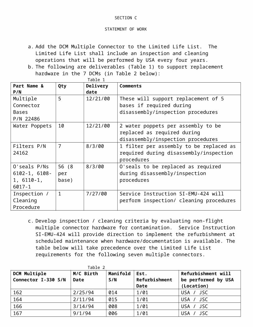
SECTION C
STATEMENT OF WORK
0106-110106 – Phase VI Glove SV799100/2 – PLSS SV799045/2 – SOP
The contractor will update the PLSS S/AD to address variations of the Airlock temperature to EMU interfaces and an increased temperature to the O2 fill line.
DELIVERABLES: Certification EMUM on or before April 01, 2002. CIARS on or before April 01, 2002. Certification closure by April 15, 2002.
Ref.: SA 368
The Contractor is directed to extend the Maintenance interval to a maximum of four (4) years on the selected SSA S/AD’s as identified as follows;
S/AD’s affected: 0101 - 10001 – CCA 0102 – 110102 – Enhanced Planar HUT 0103 - 110103 – Enhanced Arm Assembly 0103 – 112103 – RPHG Arm Assembly 0104 – 110104 – LTA 0105 – 10005 – Helmet 0107 – 10007/0107 – 11000 - LCVG 0108 – 10008 – EVVA 0110 – 110110 - DIDB 0800 – 112418 – EMUPH SEMU Harness, 12 volt
The contractor will also provide certification by analysis for the extension of the maintenance interval.
DELIVERABLES: Certification EMUM on or before May 8, 2002 CIARS on or before May 8, 2002 Certification closure by May 21, 2002
Ref. SA 262:
The Contractor is directed to complete the redesign of the Enhanced Caution and Warning System
(CWS P/N SV827600-1). A Critical Design Review shall be presented on or before July 31, 2002.
Also, the Contractor is directed to revise the following documents as applicable:
FMEA/CIL
SAR/HR
FEMU-R-001
Limited Life List

SECTION C
STATEMENT OF WORK
NOTE: The above documents will be revised under this SA, but will be submitted on a subsequent
revision to this task.
Deliverable:
One System Test Rig, P/N SVSK125650-1 shall be delivered in place at Windsor Locks on or before
2/28/02 and one Acceptance Test Rig, P/N SVSK125710-1, shall be delivered in place at Windsor
Locks on or before 4/30/02.**
Ref. SA 376
2.1.2. Hardware Development and Certification Testing
The Contractor is directed to provide additional effort to redesign the I-440 EMU Electrical Harness. This includes the effort to redesign the EEH using LEMO connectors as a replacement for the ITT Cannon connectors that will no longer be supplied. Also, the contractor shall present the FMEA/CIL changes to the SMART and SSRP. In addition, the maintenance manual will be updated to incorporate the redesigned EEH.
The dates contained in Table 1 are intended for planning purposes only
TABLE 1
Quantity Classification of EEH
Delivery Date
- Cert completion 5/15/02(Revised from 3/1/01)
3 Flight 5/31/02 (Revised from 3/28/01)3(Revised from 4) Flight 7/31/02 (Revised from 6/30/01)
7 Flight 10/15/02 (Revised from 10/15/01)7 Flight 1/15/03 (Revised from 1/15/01)
7(Revised from 6) Flight 3/31/03 (Revised from 3/31/02) 18 Training EEHs 4/11/02 (Revised from 2/month)
Ref. SA 373
CCBD H7171 – Certification of Neoflon M-400H
The Contractor is directed to certify Neoflon M-400H as an acceptable alternate to Kel-F 81. The manufacturer of Kel-F ceased production in 1991 and existing stock is low. Neoflon M-400H is chemically the same material as Kel-F. However, there can be differences in oxygen

SECTION C
STATEMENT OF WORK
compatibility depending on processing. To ensure oxygen compatibility, a new specification will be written in order to control key parameters: zero strength time and crystallinity.
Ref. SA 372
CCBD H7204 – Baselining of EMU CIL for SSRP
The Contractor is directed to modify the EMU CIL to the NSTS-22206 format (requires “Time to Effect” rationale and “Redundancy Screens” rationale) and present the EMU CIL to the SSRP on 4/24/02 and 5/22/02 for the non-EET CIL. Also, the contractor shall support the EVA Community meeting to discuss changes to the FMEA/CIL DRD #28. The agreed upon changes will be incorporated into DRD #28 under separate direction. This task does not include changes to failure mode criticalities or significant technical changes to retention rationale.
Travel: Two (2) engineers travel from Windsor Locks, CT to Houston, TX for two (2) trips each, three (3) days per trip
Ref. SA 374 CCBD H7164R1 EMU HUT and DCM ORU Data Certification for Space Shuttle Stowage as CEI’s
2.1.2. Hardware Development and Certification Testing
The Contractor is directed to certify and update the following; 1. Certify the EMU HUT ORU for launch/land stowage as a CEI in the MPLM. 2. Certify the EMU DCM ORU for launch/land stowage as a CEI in the Airlock and
MPLM. 3. Update the SEMU harness, ILCVR, and EEH S/AD. 4. HUT and DCM packaging prototype and engineering evaluation unit delivered to
ORU mockup upon task completion.5. Add crew consensus.6. SSRP and or SMART board review of CIL and FMEA test tile revision. 7. Fabricate eleven (11) sets of CCC port covers for a total of sixteen (16) sets.
Delete the following:1. HUT Launch/land stowage container XXXX-XXXXX2. DCM launch/land stowage container XXXX-XXXXX
Add the additional hardware title and part numbers to the existing parts list; 1. EMUPH SEMU harness P/N 0800-112418. 2. ILCVR P/N 0801-112983. 3. EMU Electrical Harness P/N SV822075
DELIVERABLES;1. Certification by May 29, 2002. 2. Certification of CCC port covers by February 19, 2002. 3. Three (3) sets of port covers by February 21, 2002, with the balance on May 20,
2002.
SECTION C
STATEMENT OF WORK
4. Two (2) sets of HUT hardware by May 1, 2002, with the balance on May 20, 2002. Reference EC 182135-550,550-001.
Ref. SA 384CCBD G6605R6 EMU LSS Increased Capacity Battery Certification With New Cellophane
The Contractor is directed to perform the following tasks;
Test four 4-cell battery monoblocks and manufacture one (1) Battery Assembly (SV819600-XX- XX) to support certification of a revised battery configuration with new cellophane separator material.
A laboratory analysis will be conducted on the new cellophane material.
Performance testing will be conducted on four 4-cell units.
The new configuration will be certified by test and analysis through the following activities; gas generation testing, wet life testing, rapid cycle testing, and temperature testing.
The current configuration cellophane (Flexel) will be incorporated into 2 units; part number SV819600-01-00, serial numbers 2029 and 2030. The contractor is directed to complete the manufacture of ten (10) units with the new cellophane (UCB). FLIGHT EFFECTIVITY:XN: Interim Certification Closure (GCAR Approval) 10-03-02. This Interim Cert Closure will allow usage of ICB’s on the following missions: STS-114, 01-17-03, STS-115, 04-10-03, STS-116, 05-30-03, US Increment EVA #2 AND #3, STS-117, 08-21-03, US Increment EVA #4, and STS-118, 09-25-03.
DELIVERABLES: revised as follows;5. Two (2) units, (SV819600-01-00, S/N’s 2029 and 2030, FROM: 09-30-01 TO: 06-03-02. These batteries will be shipped less battery relief valves. 6. Ten (10) units – new cellophane ONLY. These batteries will be shipped less battery relief valves. a. Six (6) units FROM: 09-30-01 TO: 10-18-02b. Four (4) units FROM: 09-30-01 TO: 12-20-02.
Ref. SA 385CCBD H7177 Incorporation of the On-orbit In-Suit Bends Treatment Procedure
The Contractor is directed to update SVHS 7800 EMU Design and Performance Requirements, BTA S/AD (SV792740/2), EMU FMEA (EMU1-28F-001), EMU CIL (EMU1-28C-001), and the EMU SAR/HR (EMU1-24-001) as a result of incorporating the On-Orbit In-Suit Bends

SECTION C
STATEMENT OF WORK
Treatment Procedure in the EVA Checklist (JSC-48023). This procedure was approved by NASA PRCB per CR S050210CE and CR S050417BN.
Ref. SA 386CCBD H7212 Update SVHS7800 and SVHS7802 for AMS-02 Magnetic Exposure and Radio Frequency Exposure
The Contractor is directed to certify EMU performance for exposure to the ISS AMS-02 (Alpha Magnetic Spectrometer High Strength Magnetic Field). The current requirement of 63 Gauss will be revised to 300 Gauss. Additionally, the Maximum recommended Radio Frequency Exposure Level Curve and Table will also be updated. Also, the contractor shall revise the following: SVHS 7800 paragraph 3.6.3 Electrical Systems, Fig. 7, Table VII and Table VIII. SVHS 7802 paragraph 3.3.2.2.5.2.8 Radiated Susceptibility, Electric Field, and associated Figure 12, Table I and II. SVHS 7802 paragraph 3.3.2.2.5.2.9 Magnetic Field Susceptibility. The revision of SAR/HR hazard will occur under separate direction.
Ref. SA 387CCBD H7167R1 EVARM Dosimeter Pocket Certification Fabrication for the Use in EMU
The Contractor is directed to extend the EVARM certification from a total of 9 man-EVA’s to 11 EVA’s per component with no limitation on the total number of man-EVA’s as long as no component exceeds 11 EVA’s with an EVARM installed.
The contractor is also directed to fabricate 30 Class I Pockets to be used on the prime and backup suits launched on the additional missions. The effectivity of using the EVARM in the EMU is revised to include all flights and increments between STS-108 (UF-1) and STS-113 (11A). Certification beyond 11A will not be considered as the dosimeters will be out of life. DELIVERABLES:
30 Class I Pockets shall be delivered on or before April 12, 2002.
Ref. SA 389CCBD H7204R1 Baselining Of EMU CIL and SAR/HR for SSRP
The contractor is directed to modify the EMU SAR/HR to the NSTS-22254 format. This format requires a 4 x 3 risk matrix chart for each EMU hazard. The contractor is also directed to update referenced flight rules in the hazard reports, as required, and present the EMU SAR/HR to the SSRP. Magnetic fields will be added as a hazard to the Hazard Report EMU-018. This task does not include changes to failure mode criticalities.
Two (2) engineers will travel from Windsor Locks, CT to Houston, TX for one (1), three day trip.

SECTION C
STATEMENT OF WORK
This update to the EMU CIL and SAR/HR takes the place of the normal June 30,2002 submittal. The EMU FMEA update will be provided on or before June 30, 2002. DELIVERABLES:
SAR/HR to NASA on or before May 30, 2002. Ref. SA 390H7120 R1 EMU SSA Enhanced Small Boot Toe Spacer Certification and Implementation
The contractor is directed to process a Class I ECO to incorporate critical dimensions into the PDA and incorporate FEMU-R-001 revisions referenced in CCBD H7120R1. The FEMU-R updates will include deletions of obsolete items and corrections.
DELIVERABLES:
Revised deliveries: From: 1) Fourteen (14) pair of toe spacers and modification kits to USA on or before February 12, 2002. 2) Certification Closure Date on or before 12/17/01. To: 1) Fourteen (14) pair of toe spacers and modification kits to USA on or before
March 22, 2002
2) Certification Closure Date on or before 2/21/02.
Ref. SA 393H7220 EMU/SSA Document Revision to Eliminate WLVTA to HUT Size Restrictions
The contractor is directed to revise the Pivoted and Planar HUT S/ADs Part I to allow the use of any size WLVTA on any size HUT. The contractor will also update the Baseline Sizing Document to include additional detail in the initial suit sizing to select the most appropriate size WLVTA for that crew member. The revision to the sizing document will allow the use of alternate size WLVTAs at the request of the crew member or as required to assure mission success. Additionally, the Maintenance Manual will be revised to remove the sizing restrictions imposed by the “Use On Code” listings.
DELIVERABLES:
Closure of ECOs on or before 09/09/02.
Ref. SA 395CCBD H7228 Addition of DPV Lever Stem Screening To FEMU-R-001

SECTION C
STATEMENT OF WORK
2.1.2. Hardware Development and Certification Testing
The contractor is directed to revise FEMU-R-001, EMU Processing Requirements and Constraints, to incorporate a verification that the helmet Combination Purge Valve (CPV) Lever Stem Subassembly is properly restrained within the CPV. The contractor will also process a class II ECO to update and clarify the Baseline Maintenance Manual, 0111-70024, and to add this screen to the Air Lock Operations Sheet. As the maintenance manual and operation sheet revisions are considered class II changes, there will be no direct deliverable associated with them.
Ref. SA 396H7221 EMU SSA Combination Purge Valve (CPV) Gasket Replacement and Flow Test Performance
The Contractor is directed to perform the following activities:
1. Obtain samples of the proposed supplier’s silicone base material for MATCO testing. 2. Re-identify CPV gasket molds to incorporate new part numbers and obtain 10 each gaskets (2807-1 and 2802-1) with material Certificate of Compliance from Jonal Laboratories. Additional Class I gaskets, 6 each (2807-1 and 2808-1) will also be procured and delivered to our customer. Start the performance of CPV/Helmet leak testing with gaskets made from the proposed replacement material
Ref. SA 397CCBD H7203 EMU LSS Increased Capacity Battery Relief Valve Modifications
The contractor is directed to redesign and certify the new Battery Relief Valve (BRV).
Certification on or before 12/17/02.
Ref. SA 401CCBD H7208 – FEMU-R-004, EMU Launch-Stowage Constraints Document Baseline2.1.2. Hardware Development and Certification Testing
The Contractor is directed to develop, publish, the new EMU Launch-Stowage Requirements Document, FEMU-R-004. The FEMU-R-004 will be a Type I document; configuration control will be the same as FEMU-R-001. Publication of baseline FEMU-R-004 shall be on or before 8/21/02 and revisions to the FEMU-R-004 shall be on or before 10/7/02.
Ref. SA 403Reference: CCBD H7186 R1 – EMU/SSA ON-ORBIT AND MAINTENANCE INTERVAL EXTENSION2.1.2. Hardware Development and Certification Testing
The contractor is directed to extend the Maintenance interval to a maximum of four (4) years on the select SSA S/AD’s described as follows;

SECTION C
STATEMENT OF WORK
S/AD’s affected:0101-10001 CCA0102-110102 Planar HUT 0103-110103 Enhanced Arm Assembly0103-112103 RPHG Arm Assembly0104-110104 LTA 0105-10005 Helmut0801-112983 ILCVR0800-112418 EMU PH SEMU Harness
SDRD affected: JSC-39194 EMU Power Harness
Deliverables: Certification EMUM on or before 08/13/02. CIARS on or before 08/13/02.For CERT Closure by 09/03/02.
Ref. SA 403 R1
The contractor is directed to revise the Radiation Dose Limits to the 8-year requirements.
Document affected:SVHS7800 EMU Design and Performance Requirements Specification
Ref. SA 404CCBD H7187 – EMU/SSA CHRONOLOGICAL LIFE EXTENSION IMPLEMENTATION2.1.2. Hardware Development and Certification Testing
The contractor is directed to certify and implement the life extensions recommended by the SSA Chronological Life Extensions Study directed under PPDO 02-2.2.3A-402. The definition of indefinate will be modified to permit extension of the DIDB restraint. A list of the hardware that will be life extended is as follows: FROM 8 TO 10 YEARS:
Component PN
CCA assembly 0101-10001CCA Skull Cap Assembly 0101-80841WLVTA 0102-82437-21 and subsJumper Loop Tubing 0102-89929Enhanced Arm Assy. 0103-110103LAA Cable (12V) 0103-212419RPHG Arm Assy. 0103-112103Enhanced Boot Assy. 0104-210895Leg Assy. 0104-210575Brief Assy. 0104-810071

SECTION C
STATEMENT OF WORK
Adjustable Waist Assy. 0104-812355BLVD 0107-81057-31 and subsVent Plenum Assy. 0107-811466Sizing Inserts 0107-82541-12 and subsLCVG Restraint 0107-82968Mini Vent Ducts 0107-89620-04 and subsEMU PH SEMU Harness 0800-112418 EMU Power Harness SHG13101723
FROM 14 TO 15 YEARS (as applicable to Planar HUT configuration):
Component PN
HUT Assembly Lable 0102-24653
Neck Ring TMG Attachment Looptape 0102-812317
DOCUMENTS AFFECTED:
S/Ads Affected: ECO0101-10001 CCA 021-02730102-110102 Planar HUT 021-02740103-110103 Enhanced Arm 021-02750103-112103 RPHG Arm Assy. 021-02760104-110104 Enhanced LTA 021-02770107-10007 LCVG 021-02790800-112418 EMUPH SEMU Harness 021-0780
SDRD Affected:
JSC-39194 EMP Power harness
Ref. SA 404R1
FROM 8 TO 10 YEARS:
Component PN
ILCVR 0801-112983
Ref. SA 407
CCBD H7240, LEAKAGE. The contractor is directed to revise ICB S/AD to restrict orientation for non-inversion in 1G, update the Hazard Analysis report, and update FEMU-R-001 and ICB Battery activation procedure (SVHS14479) to add revised formation charge stand times.

SECTION C
STATEMENT OF WORK
CERT closure by 10/30/02
Ref. SA 408
CCBD H7242, I-300 DCM ON-ORBIT MAINTENANCE INTERVAL EXTENSION TO 730 DAYS. The contractor is directed to recertify the I-300 DCM for an On-Orbit Interval of 730 days. The CEI 300 S/AD SV792294/2, FEMU-R-001, and Limited Life List will be revised and information will be provided for the FEMU-R-003 ISS On-Orbit Maintenance Requirements (ref: CCBD H7210). CERT closure by 10/11/02.
Ref. SA 409CCBD H7038R2 – EMU SMALL PLANAR HUT DEVELOPMENT AND CERTIFICATION – DESCOPE2.1.2 Hardware Development and Certification Testing
The Contractor is directed to delete the following;
ILC: Review/incorporate Class I and II ECO’s.Complete Internal Design release of BOM.
Receive CFE to support Cert Test program.Order Arm Bearing test fixtures. Release Class I Documentations – FMEA/CIL, LLL , SAR/HR report.Submit CDR package.Present CDR at JSC. Evaluate TMG Stiffener evaluation.
HS: Perform physical properties testing of SVHS 14822 and 14823 laminating system to provide a replacement material for the unavailable Epon 815/curing agent U laminating
system used to wrap the steel arm rings and manufacture the vent ducts. Develop shell fiberglass 5 ply lay-up method around neck ring to reduce wrinkles.Complete tooling manufacture;
Purge Duct Fitting (-201 Saddle) master.Purge Duct Fitting (-201 Saddle) trim fixture. Outlet Duct/Purge Duct joint scribe fixture. Inlet Duct Trim Fixture. Arm bumper bonding fixture. WLVTA connector block bonding fixture. Harness Pin bonding fixture.
Release Class I and Class III operation sheets. Release of SV810001 Small Planar HTS drawing.
Process manufacturing prove out – 208 Purge Duct.
Ref. SA 410CCBD H7239 Update SVH7800 and SVHS7801 For EMU RF Shielding Effectiveness/Crew Protection

SECTION C
STATEMENT OF WORK
The contractor is directed to revise the following EMU Specifications: SVHS7800 and SVHS7801: to document EMU shielding effectiveness/crew protection for non-ionizing RF radiation as encountered in STS/ISS EVA environment. CERT closure by 11/08/02.
Ref. SA 411CCBD H7244 – EMU SSA MAXIMUM ABSORBANCY GARMET (MAG) INSERT REPLACEMENT2.1.2 Hardware Development and Certification Testing
The Contractor is directed to locate and approve a new supplier for the MAG insert. This will require the contractor to obtain and evaluate samples of inserts from potential suppliers. Once a new insert is selected, the contractor will update the MAG drawing/procedure with the new insert(s) and provide certification for NBL/On-orbit use. The contractor is also directed to update the existing SMCAR to new Government Certification Approval Request (GCAR).
Deliverables: Cert by 01/15/03.
Ref. SA 412CCBD H7246 – DIDB –03 DESIGN CERTIFICATION/IMPLEMENTATION 2.1.2 Hardware Development and Certification Testing
The Contractor is directed to certify and implement the new –03 configuration Disposable In-Suit Drink Bag (DIDB). The new configuration incorporates a silicone Sure Shot valve with a cracking pressure of 1.25 psi and .130 inch slit size. The lower cracking pressure and a larger slit size will make drawing water from the DIDB easier in a 4.3 psi environment. Certification will be accomplished by analysis based on demonstration.
Deliverables: 25 Class I Units to support STS-113 (11A) Flight – by 09/10/02. CERT closure by 08/28/02.
SECTION C
STATEMENT OF WORK
2.2 Program Provisioning
The contractor shall provide all resources necessary to support the contract program provisioning effort. Program provisioning requirements shall be baselined on an annual basis and shall consist of field activities, special studies, special tests and supplier supportability and technology obsolescence. In addition, program provisioning shall support ISS and Shuttle Program interoperability with international partners; manifesting, and scheduling issue resolution; international partner hardware and operational issues; EMU processing contractor issues; unscheduled EVA community meeting support; interface compatibility, and other unplanned EVA related activities.
Ref: SA 289
EMU LSS Allow Alternate Pressure Gauge With A Reduced Bourdon Tube Flatness
The contractor is hereby directed to create an alternate pressure gauge that incorporates the use of drawing 0481-8546 Revision A, which replaces drawing 0481-8541. Use of 0481-8546 Revision A allows for an increased range in Bourdon Tube flatness from 0.025 to 0.057 inches vice the original drawing’s range of 0.037 to 0.057 inches. The new specifications will allow the Bourdon Tube to be coiled in a fashion that will meet wrinkle specification requirements. The title and associated part number information is as follows:
Title: Part Number:
Pressure Gauge SV767706-X
The following documents shall be updated to reflect the new nomenclature associated with this part:
SV767706SV779301SV822066PLSV822066-1PLSV822066-2PLSV779301-19PLSV779301-21
Ref: SA 288
The contractor is hereby directed to determine the compatibility of AIRX44 cleaning solution with the generic materials comprising the SSA and the LSS. A material evaluation will be performed with a literature review to assess compatibility to clean blood and/or bodily fluids from Class I SSAs and external portions of the LSS during ground operations.
The following document shall be updated accordingly:

SECTION C
STATEMENT OF WORK
CPPHSS
Ref: SA 292
The contractor is hereby directed to revise the ORU SEMU configuration per SED13101492-320.
The following document shall be updated to reflect the new configuration:
SED 13101492-320 ORU, SEMU Configuration
Ref: SA 293 EMU Battery Wet-Life Extension
The contractor is hereby directed to extend the wet-life of the current battery design from 170 days to a maximum of 270 days by limiting the out-of-freezer storage time to a maximum of 135 days.
The following documents shall be updated accordingly:
SEMU1-19-001 Limited Life ListSHVHS 7800 EMU Design & Performance Requirement Specifications
Certification closure by March 2, 2001.
Ref: CCO 299Increased Capacity EMU Battery
1. Initiate the activities associated with advancing the configuration of eighteen (18) SV819600-00-01 Class 1 Increased Capacity Batteries (ICBs) to SV819600-01-00. This will segregate the 18 flight acceptable batteries from seven (7) SV819600-00-01 non-flight ICBs that were assembled with inadequately controlled materials (U-wrap Flexal Cellophane). The remaining seven (7) SV819600-00-01 batteries will be downgraded to Class II fidelity. The Contractor shall implement material handling procedures at BST (the Monoblock supplier), that will be incorporated into the next ICB configuration.
2. The Contractor is also directed to advance the configuration on the following ICBs:INCREASED CAPACITY BATTERY INVENTORY
HS ICB S/N
BST CURRENT
BATTERY CONFIGURATION
ACCEPTABLE FOR FLIGHT
CONFIGURATION AFTER CCBD G6605R5 APPROVAL
PLANNED USE
Completion Date
2010 023 SV819600-00-01 YES SV819600-01-00 FLIGHT 5/1/012012 025 SV819600-00-01 YES SV819600-01-00 FLIGHT 3/31/012014 027 SV819600-00-01 YES SV819600-01-00 FLIGHT 3/31/01
2026 041 SV819600-00-01 YES SV819600-01-00 FLIGHT 5/1/012027 040 SV819600-00-01 YES SV819600-01-00 FLIGHT 5/1/01
SECTION C
STATEMENT OF WORK
Ref. SA 325NEW Configuration DIDB Certification / Implementation to minimize Inadvertent Actuation
The contractor is hereby directed to certify and implement the new configuration for the Disposable In-suit Drink Bag (DIDB). Certification is to be accomplished by analysis of confidence test data conducted on the new configuration. The “Confidence Test Plan” shall be submitted to CTSD for approval prior to performing the confidence testing.
The following are deliverables:
Quantity Nomenclature Due Date
12 Prototypes for NBL Training ship to CTSD 09/26/01
25 Class 1 Units to Support STS-108 (UF-1) Flight 10/31/01
40 Class 1 Units to Support STS-109 (HST) Training and Flight 11/16/01
Certification closure by 10/23/01.
Ref. SA 328ORU Tool Kit Design, Fabrication and Certification
The contractor is directed to perform the following tasks:a. Certify and transfer the spare ORU Tools developed from CCBD
H7112 to USA. Certification shall include the development and submittal of an EMUM to NASA by September 24, 2001, which shall detail the ORU change out rationale for the shuttle. These spare ORU Tools will fly in the Servicing Kit on a Type “A” TPS to support HST.
b. Create and certify an ORU Tool Kit by flight 9A (STS-112) that is complete with tools and components necessary for use on Station, MPLM and Shuttle.
c. Fabricate three (3)(one station, two spares) Class I and two (2)( one Prototype non-deliverable and one training unit) Class III ORU Tool Kits complete with tools and components as defined below:
QUANTITY ITEM DESCRIPTION2 Hex head driver, 3/8” drive
3 Ball hex driver, 3/8” drive 1 Torque limiting drive, 1/4” 1 Torque wrench, 3/8” drive 1 Open end wrench, 5/16” 1 Universal Joint, 3/8” drive 1 3/8” extension, 4” 1 Adaptor, 1/4”Female to 3/8” male 2 SOP Over-ride protection tool 2 DCM O2 fill- line O-seal spare

SECTION C
STATEMENT OF WORK
4 DCM O2 fill- line backup ring spare1 PLSS Interface, FW T8 filter, O-seal spare8 PLSS Interface, LCG Port, O-seal spare2 PLSS Interface, Vent Loop, O-seal spare 2 PLSS Interface, Secondary, O-seal spare2 DCM Interface, FW O-seal spare8 DCM Interface, LCG water, O-seal spare2 DCM Interface, Sense port, O-seal spare2 DCM Interface, Purge valve port, O-seal spare2 DCM Interface, Secondary, O-seal spare2 SOP Interface, O-seal spare
25 Teflon squares, 2” X 2” 25 Teflon squares, 5” X 7” 2 Wrist straps, ESD control1 Kapton Tape roll
1 Scissor 3 Interface plates
1 Vent plug for CCC port
Ref.: SA 355
The contractor is hereby directed to revise the EMUM submittal date from September 14, 2001 to November 9, 2001 and update the tool list and delivery dates as follows:
The contractor will deliver 4 kits. Each ORU Tool Kit will contain the following tools and components designed and fabricated by the contractor:
QTY Item Description
1 HEX HEAD DRIVER, 3/8” DRIVE 1 HEX HEAD DRIVER, 3/8” DRIVE 1 BALL HEX DRIVER, 3/8” DRIVE 1 BALL HEX DRIVER, 3/8” DRIVE 1 HEX DRIVER, 1/4" DRIVE 1 RATCHET, 3/8" DRIVE SEALED 1 HANDLE, 1/4" DRIVE 1 TOURQUE LIMITING DRIVE, 1/4” 1 TOURQUE WRENCH, 3/8” DR 1 OPEN END WRENCH, 5/16” 1 UNIVERSAL JOINT, 3/8” DRIVE 1 3/8” EXTENSION, 4" 1 ADAPTOR, ¼” FEMALE TO 3/8” MALE 2 SOP Over-ride Protection Tool 2 DCM O2 fill-line O-seal spare (lubricated) 4 DCM O2 fill-line backup ring spare 2 PLSS Interface, FW T8 Filter, O-seal spare 8 PLSS Interface, LCG Port, O-seal spare 6 PLSS Interface, Vent Loop, O-seal spare

SECTION C
STATEMENT OF WORK
2 PLSS Interface, Secondary, O-seal spare 2 DCM Interface, FW O-seal spare 8 DCM Interface, LCG water, O-seal spare 2 DCM Interface, Sense port, O-seal spare 2 DCM Interface, Secondary, O-seal spare 2 SOP Interface O-seal spare25 Teflon Squares 2 Wrist Straps – ESD control 1 Kapton Tape Roll 1 ScissorItems to be stowed in the ORU Tool Kit but will not be designed or fabricated as part of this CCBD.
4 Interface plates2 Vent plug for CCC port8 Electrical Covers2 Oxygen Line Covers
10 Foam tip Swabs2 O-ring Picks1 Dynaband4 pair of Powder Free Latex Gloves
Ref. SA 335CCBD H7138F, Middeck EMU Battery Charger, ISS Certification and Production of Additional Flight Unit to Support STS-109
The contractor is hereby directed to: 1. Support USA with certifing five (5) Middeck Battery Chargers and the increased capacity
EMU battery (SV819600) for the ISS environment.2. Provide a ROM for the fabrication of an additional class I middeck battery charger for
STS-109.3. Incorporate corrective action firmware and LED intensity changes into the configuration
changes for the increased capacity battery (SV819600).
Ref. SA 336CCBD H7120 EMU SSA Enhanced Small Boot Spacer Cert. And Implementation
HSSSI is hereby directed to certify and implement the modified Toe Spacer in the Enhanced Small SSA Boot TMG that was developed and evaluated under PPDO 00-2.2.3C-208. FEMU-R requirements for boot/foot restraint interface will be evaluated as part of this task and revised if necessary. HSSSI will revise manufacturing documentation and generate modification instructions to retrofit all delivered Enhanced Small SSA Boot TMG’s (Class I and III).
Ref. SA 337: CCBD H7145R1 EMU SSA In-line Cable Voltage Regulator (ILCVR) Certification
The contractor is hereby directed to:

SECTION C
STATEMENT OF WORK
Perform 24 cert thermal cycles as part of the certification to the ILCVR assembly. Deliver six (6) each in Line Cable Voltage Regulator 0801-112983-01 and O2 Pocket
Connector Extension 0102-812936-01 on or before 12/19/01.
Certification closure by 11/8/01.
2.2.1. Field Activities
The contractor shall perform field activities at NASA/JSC in support of the EMU program. Such activities shall consist of EMU Program management, interface coordination, equipment design, prototyping, development, testing, maintenance, repair retrofit, purchasing, shipping, receiving, Russian Orlan suit flight and training equipment maintenance, enhanced EMU hardware and ancillary equipment, and technical and engineering support. Such activities shall not include the preparation of Orlan hardware for flight. Field activities may be required at sites other than NASA/JSC throughout the contract period of performance. The contractor shall prepare and submit a Field Operations Support Plan in accordance with Data Requirement Description No. 16.
The contractor shall perform the following field activities:
a. Contractor activities on-site shall conform to all JSC requirements including personnel certification, training and safety.
b. Provide "Quick-Look" summary level and engineering reports for all testing and evaluations that are supported by the contractor.
c. Maintain procedures to ensure compliance with ISO 9001 requirements.
d. Maintain controlled process, man-rated, Class I and /or Class II EMUs at CTSD with Provisioning for contingency flight processing.
e. Prepare test, installation, and checkout documentation in support of ground, flight, and EVA task activities and operations for EMUs, Russian suits, and EVA equipment, as directed by NASA or required by JSC safety requirements.
f. Engineering evaluation of proposed technical and FEPC processing changes including but not limited to CCBDs, EC/ECOs, DRs, RDRs, YTNs, WSTF requests, updates to S/ ADs, FEMU-R-001 EMU Processing and Constraints; SVHS-7800 EMU Design and Performance Requirements Specification, and MUAs. The contractor shall also provide Test Readiness Review (TRR) packages and limited life item management.
g. Provide pre and post mission EMU operations including; mission support, generation and maintenance of Mission Operations Plan, real-time EVA mission related engineering and technical capabilities, preparation of flight checkout and flight maintenance procedures, EMU flight readiness verification support, and maintenance of Bldg. 7 EVA Operation Room.

SECTION C
STATEMENT OF WORK
h. Provide assistance with the conduct of manned and unmanned tests in JSC facilities, including vacuum and thermal/vacuum chambers.
i. Perform anomaly analysis, redesign, fabrication and certification of the EMU systems described in paragraph r below.
j. Conduct the investigation of "out-of-family" (i.e., outside the experience base) conditions encountered during processing and flight and recommend corrective action, as appropriate.
k. Assist the EMU Subsystem Manager and other NASA organizations in developing EMU enhancements and associated EVA related equipment, and assuring flight readiness and achievement of mission goals.
l. Perform special evaluations of EMU and related EVA related equipment and facilities in order to achieve increases in the operating capability and safety margins of the equipment.
m. Provide manpower and materials to perform such activities as: rapid response anomaly investigations; corrective actions; certification; design; fabrication; hardware end item replacement, adjustment and retest; space awareness presentations and specialized engineering documentation/tests.
n. Maintain shop and laboratory facilities on site at JSC to support the activities in paragraph 1 above. This includes maintenance, documentation and related activities of all EMU ground support equipment (GSE) located at JSC, except that belonging to the Flight Equipment Processing Contractor (FEPC). Responsibilities include property accounting, inventory control, administration and reporting, VAX/Oracle database maintenance as required. This also includes GSE configuration maintenance and operation, implementation of changes required to assure similarity to flight-type checkout equipment, maintenance and issuance of bin stock, tools, expendables, and miscellaneous parts.
o. Maintain, develop, and fabricate EMU and EVA equipment including space suit, life support, mockup, laboratory support, and neutral buoyancy type equipment.
p. Perform design, analysis, fabrication, documentation, and certification activities for special EVA related equipment used in conjunction with the EMU.
q. Fabricate and maintain EMU related test equipment and provide new EMU related GSE as needed to support currently projected Shuttle and Station onsite processing activities.
r. Maintain configuration records, mini-databooks, and design control of EMU and Russian suits and EVA systems for neutral buoyancy and other non-space use including the use of oxygen-enriched air (Nitrox).
s. Establish and maintain an engineering data center at NASA/JSC. This data center shall have up-to-date copies of EMU program documentation including S/ADs, FEMU-R-001 EMU Processing and Constraints; SVHS`-7800 EMU Design and Performance Requirements Specification; EMU Certification Reports; "Quick-Look" Reports; failure reports; EMU drawings; EMU Master Authorized Change Records; and other documentation required to carry out the

SECTION C
STATEMENT OF WORK
above activities for the EMU and Russian EVA related equipment. The contractor shall also maintain "Update and Distribution System" for EMU/EVA related equipment, Standard Procedures and drawings, TPS, DR, DRL, drawing files, limited life item tracking, and the Flight Configuration Management System. The contractor shall coordinate the paper flow (RDRs, PDs, CCBDs, ECs) and problem resolutions including CRM tasks.
t. Provide transportation among JSC facilities for test support activities. Perform shipping and receiving capabilities for EMU/EVA related materials and hardware.
u. Operate and maintain a Bonded Stores Facility/Logistics in Bldg. 7A JSC for EMU/EVA related materials and hardware.
v. Assist the EVA Project Office in EMU and EVA related equipment management for SSP, MIR, and ISS assembly and operation missions. This shall include participation in the EMU Board, EVA Hardware Board, Configuration Change Board reviews, and EVA IPTs as directed. It shall also include the planning and implementation of hardware design, development, testing and manufacturing, and provide technical coordination and review for verification of EVA related equipment.
w. Provide manpower and materials to perform crew procedures development and verification.
x. Conduct and support manned and unmanned tests in JSC facilities, including neutral buoyancy facilities, Zero G and laboratory settings.
y. Provide engineering development and conduct tests to ensure EMU- interoperability with Russian Orlan suits, Russian EVA related equipment, and equipment provided by other international partners.
z. Provide technical coordination, engineering support, and testing to ensure proper integration of the EMU into the ISS. This shall include identification and resolution of problems/issues, engineering support for definition of interface requirements, conduct of tests to ensure proper interface and operation of the EMU with the ISS, and in the ISS EVA environment.
aa. Assist the EVA Project Office and other NASA organizations in assuring proper EMU and EVA related equipment manifesting and control.
bb. Provide assistance to the EVA Project Office for EMU and EVA equipment logistics. It shall support maintaining a database with inquiry and read only access options for inventory control, tracking and allocation. Responsibilities shall also include enabling logistic control of flight operational, development, and training hardware, tracking hardware quantities by name, part number, and serial number, and compiling data on current and future hardware configurations.
cc. Define EMU command and data interfaces for robotics.
“EVA related equipment” is defined as equipment that is directly attached to the EMU and/or supports its operational, functional, or interoperability capabilities. Examples of EVA related

SECTION C
STATEMENT OF WORK
equipment include AAPs, tethers, donning handles, IFDs, MAGs, DACTs, and other similar equipment.
Ref. SA 114ee.The Contractor shall revise FEMU-R-001, “EMU Processing and Constraints Document” to clarify the External Visual Inspection and Periodic/Quadrennial Inspection of “Vent Pad for Security of mount.”
This implementation shall be on or before January 13, 1999.
REF. SA 316 &Ref: CCO 274 2.2.1 Interfaces- ISS Joint Airlock
Due to limited stowage availability within the shuttle mid-deck, the contractor is hereby directed to begin work in defining new certification requirements for hardware stowage within the shuttle's joint airlock. In an effort to support flight STS-104/7A requirements, the contractor is hereby directed to complete the following tasks no later than November 27, 2000.
1. HSWL is to generate a preliminary document that defines the differences between the current stowage environment and those found within the joint airlock.
2. HSMS is to define the packaging arrangement that will be used within the joint airlock.
3. Upon completion of steps 1 and 2, HSWL shall submit the environmental and packaging information to NASA officials for review, adjustment and/or concurrence.
4. HSWL shall develop preliminary certification requirements for items to be stowed within the joint airlock.
5. The JAL was opened up for stowage of additional items. The following increment 3 GFE items were identified and stowed in the JAL:
Crew, or Tube Socks (standard cotton socks), P/N 528-40802-1, -2 Woodsman Socks (wool blend), P/N ST17C3307-03 Moleskin (on rolls), P/N 528-43041-1 Comfort Gloves, P/N 0106-84906-03/04 Mosite Pads, P/N TBD
HSWL shall prepare a revision to acceptance of use EMUM (EMUM1-0560R1) that summarizes the certification status of the additional hardware, and submit to NASA XA.
Ref. SA 341 (Ref.: CCO 282)Phase VI Processing and Training
In support of training and flight activities, the contractor is hereby directed to perform the following efforts associated with the processing and training of Phase VI gloves:
A. Receiving/Bond Room, including receiving, storage, & record keeping.
SECTION C
STATEMENT OF WORK
B. Neutral Buoyancy Laboratory (NBL) support including installation of wrist disconnects, sizing, TMG repair, structural and leakage evaluations as well as transport to and from the NBL. Post NBL test activities include checkout, rinse, dry and storage.
C. Prep and post activities include installation of wrist disconnects, sizing, structural and leakage evaluations, rinse/dry/store, as well as transport.
D. Fitchecks include installation of wrist disconnects, sizing, structural and leakage evaluations and support of Glove Box Evaluations.
E. 1-G activities include installation of wrist disconnects, sizing and structural and leakage evaluations.
F. Glove Box Evaluation activities include installation of wrist disconnects, sizing, structural and leakage evaluations, and technical support to operate the chamber for evaluations as well as transport.
G. Maintenance of the Phase VI Glove after 40 hours of use, which includes:
1. Wrist disconnect removal, inspection, assembly, and reinstallation.2. Removal of TMG, inspection of the interior and exterior of TMG3. Inspection of the restraint.4. Inspection of the bladder.5. Overall glove inspection of all components during this maintenance period.
H. Flight processing includes Class I Phase VI Glove build up, fitchecks, SAFER Reach evaluations, Bench Reviews, ETA Build Ups, and Flight Prep and Post. The following flights are being supported:
1. STS-92/3A (Post flight through the end of December 10/11/00 Launch Date)
2. STS-97/4A (Launch Date: November 30, 2000)3. STS-98/5A (Launch Date: February 7, 2001)4. STS-102/5A.1 (Launch Date: March 8, 2001)5. STS-100/6A (Launch Date: April 19, 2001)6. STS-104/7A (Launch Date: July 12, 2001)7. STS-105/7A.1 (Launch Date: August 10, 2001) Processing
Assistance provided to USA8.
I. Technical issue resolution including Yellow Tag Notice & Discrepancy Reports.
J. Procedure maintenance.
K. Program and Technical Management (including safety review) for Phase VI Processing Activities
Ref. SA 303

SECTION C
STATEMENT OF WORK
1.2.1 Field Activities
This modification is issued to incorporate the implementation of GSFC HST requirements for thermal vacuum bake-out for eight (8) pairs of EMU Phase VI glove TMGs, part number 0106-812144. These eight pairs of TMGs will undergo the following procedures:
A. Remove from production just prior to the installation of the 12-volt electrical heater harness.
B. These TMGs (0106-812107) will be sent to CTSD/JSC. CTSD will perform the thermal vacuum bake-out as a government furnished service. The contractor will ensure that no RTV is added during processing or fabrication subsequent to the bake-out.
C. CTSD/JSC will return TMGs to ILC Dover for completion of the manufacturing process.
D. The deliverables to USA shall consist of the following: 1. Four (4) Class I TMGs (0106-812144)2. Four (4) Class I TMGs (Back-up TMGs)(0106-812144)
Ref. CCO 3072.2.1 Field Activities
The contractor is hereby directed to perform the following efforts in addressing the certification impact to the EMU of allowing bandages, Dermabond, Steri-strips, Bioclusive, and Tegaderm to be applied to the fingers prior to donning the EMU. These items are currently flown as part of the Shuttle Orbiter Medical System (SOMS) but are currently not approved for use within the EMU. The output from this task will be an Engineering Memorandum for flight 7A, documenting the impacts of these items being present in the EMU Vent Loop. An Engineering Memorandum providing full certification rationale will be submitted after 7A.
Ref. SA 326EVARM Dosimeter Pocket Certification fabrication for the use in EMU
The contractor is directed to certify and fabricate the Extravehicular Activity Radiation Monitor (EVARM) dosimeter pockets, part number SED 13101835, for the Liquid Cooling and Ventilation Garment and Communication Carrier Assembly. These EVARMs shall be used on nine extravehicular activities in the increment number 4 manifest. Specific activities to be accomplished are as follows:
a. Revise the Interface Control Document, review materials certifications, generate
materials usage agreement, review test results, hazard and reliability analysis and write acceptability for multiple use Engineering Memorandum (EMUM).
b. Generate Failure Mode and Effects Analysis assessments for pockets and EVARM dosimeter integration
c. Generate Government Certification Approval Request for pockets and add a note to CCA drawing to allow pockets to be added as a field option.
d. The contractor is also directed to support the following:
1. Space Station Airlock Test Article test

SECTION C
STATEMENT OF WORK
2. Support bench reviews 3. SSRP 4. SMART reviews5. PRCB 6. Certification of Flight Readiness and Flight Readiness Reviews.
The delivery schedule for the EVARM dosimeter pockets is as follows: Quantity Class Delivery Date
Thirty (30) Class I pockets 09-07-01Fifteen (15) Class III pockets 09-07-01Fifteen (15) Class III pockets 09-07-01
Ref.: SA 343Plasma Contractor Unit (PCU)
A. The contractor is directed to determine the catastrophic and critical effects of plasm discharge on the EMU during EVAs in the event of Space Station PCU failure. The contractor will assess for:
Direct electrical injury to the crewmember caused by sneak circuit through EMU Battery/Biomed/EMU Electrical System.
EMU susceptibility to plasma discharge from Corona affect of O2 leakage or sublimator H2O.
Damage to EMU electrical components resulting from exposure to arc discharge. Evaluate critical effects of molten aluminum in contact with EMU suit materials. Assess potential impact of internal suit arcing (effect on bladder, CP).
B. The contractor is further directed to perform initial development activities for EMU/ EVA crewmember protection against Plasma arcing, which shall include the following activities:
a. Requirements Generationb. Design Concept / Prototyping c. Design Reviews
The efforts associated with activities (a) through (c) include travel for one initial, coordination meeting and up to two design meetings at JSC.
C. The contractor is directed to conduct formal sample testing with ISS/EMU consensus on the test plan and interpretation of the results and continue to participate in the weekly PCU Technical Team meeting. MSFC Testing Support will be provided to HSSSI as a Government provided service. No costs are included in this PPDO for MSFC support. Activities are as follows:
Provide reliability assistance and analysis of the PCU Report Prepare Test Plan for EMU sample material and support MSFC testing. Prepare Test Plan for EMU Accessory Materials (ERCA, SAFER, REBA, etc)

SECTION C
STATEMENT OF WORK
Reconcile Plan with MSFC Reconcile Plan with PCU Tiger Team Reconcile Plan with NASA EC5/XA/S&MA Support MSFC EMU Material Plasma tests Prepare Quick Look test report(s). Prepare analysis of Test result/prepare HS recommendations for results Reconcile with EMU Program Prepare Test Report/presentation for EC5, XA and S&MA Document results in EMUM Travel: 3 trips to MSFC [one(1) person, one (1) trip for two (2) weeks, two (2)
trips for one (1) week.]
DELIVERABLES
EMUMS to be submitted to XA on or before January 31, 2001, which address the following topics:
Ignition of suit oxygen atmosphere. Molten Aluminum contact with suit materials causing catastrophic damage. Affect of –140V electrical discharge arcing on SSA materials. Electrical issues summary memorandum(s). Ground rules and requirements associated with the EMU. Cost, schedule, technical trade-off of insulation options with recommendation
(presentation at JSC). Prototype/mock-ups of insulating concepts. Feasibility/concept review meeting- TBD
Ref.: SA 345
The contractor is directed to certify and implement the new configuration Disposable In-suit Drink Bag (DIDB). Certification will be accomplished by analysis of confidence test data for the new configuration, which will be generated and submitted to CTSD for approval prior to confidence testing.
Ref. SA 414CCBD H6830R3 – IMPLEMENTATION OF THE NEW EEH CONFIGURATION2.2.1 Field Activities
The Contractor is directed to review the certification of EVA cables and CCEM pigtails and generate an Acceptability for Use EMUM covering the use of these items in the EMU. This effort includes analysis by Materials, Systems, and Design to provide rationale for use within the EMU vent loop. The EMUM will be released NTL 13 days after receipt of all certification paperwork and supporting documents.

SECTION C
STATEMENT OF WORK
2.2.2. EVA Preflight and Real-Time Mission Support
The contractor shall provide preflight and real-time support for simulations and flight. Such support shall encompass plant as well as field facilities and will include a presentation by the contractor at the Flight Readiness Reviews (FRR) of a contractor-prepared FRR package. For missions without scheduled EVA, deviations to the real-time support baseline plan may be documented by letter to the Contracting Officer. During EVA, scheduled or unscheduled, the contractor shall be prepared to support tests and evaluations involving the use of training or flight hardware, and shall provide engineering expertise at the plant, in the field at JSC, and at major subcontractor sites during EVA missions.
2.2.3. Special Studies
Special Studies shall comprise necessary analyses and evaluations, including prototype hardware, which are required to improve safety, increase functionality, enhance cost effectiveness or provide specialized information aiding in the utilization of the EMU under various conditions. Special Studies will be directed by NASA. The contractor shall complete a report documenting the results of each special study accomplished using a contractor generated format.
2.2.4. Special Testing
Special testing shall be performed for purposes of expanding performance envelopes of EMU components; exploring off-nominal conditions; evaluating alternate concepts or designs; and performing special interface evaluations with other EVA-related systems. Reports covering the results of such activities will be prepared and submitted in accordance with Data Requirement Description No. 17.
2.2.5. Supplier Supportability / Obsolescence
As directed, the contractor shall identify an acceptable alternate supplier and recertify alternate supplier and the affected EMU hardware. If redesign is required, the contractor shall, as directed, redesign the affected hardware and certify alternate supplier.
As directed, the contractor shall resolve hardware, materials, components, and process obsolescence issues which may result in the loss of EMU production, repair, and failure analysis capabilities based upon an EMU Program life projected through December 31, 2020.
As directed, the contractor shall certify replacement materials and/or processes identified under 4.2 and 4.3.
2.3 EMU Enhancements
The contractor shall provide the necessary resources and carry out performance, process, technical, cost reductions and safety related enhancements to the EMU. EMU enhancements shall be based upon the following objectives which are not in order of importance:
a. Increase EMU protection from harmful radiation.

SECTION C
STATEMENT OF WORK
b. Decrease up and down weight; reduce operations costs, both on-orbit and on the ground; reduce sparing; decrease production costs.
c. Increase the operational envelope in terms of EVA duration and the ability to sustain thermal extremes outside the current envelope of performance.
d. Ability to sustain lower and higher metabolic rates.
e. Increase safety both on the ground and in orbit by making design improvements which increase operating margins and safety factors.
f. Improve EMU robustness and resistance to damage from interfacing systems and equipment.
g. Extend EMU maintenance and refurbishment intervals.
h. Improve glove fit and mobility; assure cost-effective, on-orbit replacement of high-wear glove components; maintain or improve hot and cold thermal protection; and reduce fabrication costs.
i. Increase in micrometeoroid / orbital debris protection so as to provide a probability of no penetration (PNP) greater than the current capability of the EMU.
j. Reduce on-orbit EVA preparation and post EVA operations time.
SA 378H7044R3 ECWS
The Contractor is directed to perform certification and production of the Enhanced Caution and
Warning System (ECWS) P/N SV827600-1 and the Item 156 Electrical Harness. This effort is to
support replacement of current CWS inventory that will begin to expire in June of 2003. Also,
the contractor is directed to perform a Certification Serial Data Transfer Test.
2.4. Anomaly Analysis
The contractor shall provide necessary resources and carry out anomaly analyses and corrective action determination for hardware which fails to meet performance requirements, including useful life. This task shall determine cause of failure; determine corrective action to prevent recurrence; identify mission impact and rationale for flight, if applicable; and recommend disposition of affected items.
SECTION C
STATEMENT OF WORK
Anomaly analysis shall proceed immediately upon receipt of a failed item and shall be carried out in accordance with Data Requirement Description No. 18.
3.0 Hardware
3.1 Hardware Provisioning
The contractor shall provide the resources required to carry out the fabrication, assembly, acceptance testing, and production of flight and training hardware. Hardware provisioning shall include EMU hardware and other EVA related hardware, and materials of certified design for the purpose of increasing EMU hardware inventories to meet Shuttle and ISS manifests; production of enhanced and/or replacement items; and retrofit kit production for maintaining a Probability of Sufficiency (POS) as discussed in Paragraph 4.4 PPS. The exact configuration of each item, as depicted by the dashed part number, shall be the latest certified configuration, unless otherwise approved by NASA.
Provisioned EMU Hardware is delineated under Section J-8 - EMU Hardware Provisioning List which is hereby incorporated into the Statement of Work.
Ref. SA 5 3.1.1 HARDWARE PROVISIONING
The contractor is directed to add an additional fabric piece to the IDB Restraint Strap on the Planar HUT to eliminate peel failure mode and the contractor is to provide retrofit kits for existing units.
Ref. SA 84 3.1.2
The contractor shall design, certify, and implement the EMU SSA Extra Short Lower Arm Assembly. The Extra Short Lower Arm Assembly will use the existing Size 01 Power Harness. The contractor will produce 8 pairs of the Extra Short Lower Arm Assemblies (3 training and 5 flight pairs). Delivery of the first training pair will be by 3/31/99 and the delivery of the first two flight pairs by 9/15/99. The remaining five pairs will be delivered by 11/15/99.
Certification closure date by 7/15/99.
Ref. SA 963.1.3 EMU SSA Phase VI Glove ProductionThe contractor shall produce and deliver fourteen (14) pair of Phase VI Gloves as directed by NASA Technical Direction in FY 99. These fourteen (14) pair of Phase VI Gloves are intended to provide flight and back-up Gloves for EVA crewmembers through flight 4A. Size definition of these Gloves will be provided via Technical Direction by the NASA EMU Contract Technical Manager.
Delivery shall be 5 months after receipt of technical direction.
Ref. SA 209
SECTION C
STATEMENT OF WORK
The Contractor is directed to incorporate the following configuration changes into ten (10) pairs of Phase VI Gloves:
1. Install teflon liner into bladder, flocking of bladder to flange, and turn restraint flange seam allowance away from bladder.
2. Revise the whipstitching method used for ORU bracket attachment, apply a second coat of edgelocking to three high wear seams, transition of index finger base panel seam allowance from 5/32" to 7/32", and revise manufacturing process to improve bladder anchor tape bond strength consistency.
3. Modify the Predelivery Delivery Acceptance document to remove Manned Pressurized Time from gloves upon delivery and to exclude TMGs from break-in cycling.
4. Modify Acceptance Data Package to document that the six-hour break-in requirement is satisfied prior to delivery and the start of Manned Pressurized Time tracking.
Ref. SA 184The contractor shall incorporate the 12 Volt electrical system into two (2) pair of Phase VI Gloves to support flight 4A. The remaining twelve (12) pair of Phase VI Gloves will be delivered with 3 Volt electronics. (The above 14 pairs of gloves were directed under SA 96.)
Ref. SA 973.1.4 Additional EMU SSA Phase VI Glove CustomizationsThe contractor shall increase the inventory by adding six (6) additional customizations. Direction to perform these six (6) glove customizations will be provided by NASA Technical Direction in FY 99.Delivery shall be 9 months after receipt of technical direction.
Ref. SA 184The contractor shall incorporate the 12 Volt electrical system into (6) pairs of the Class III customization Gloves to meet training requirements. (The above (6) pairs of gloves were directed under SA 97.)
Ref. SA 210The Contractor is directed to incorporate the following configuration changes into six (6) pairs of Phase VI Customization Gloves:
5. Install teflon liner into bladder, flocking of bladder to flange, and turn restraint flange seam allowance away from bladder.
6. Revise the whipstitching method used for ORU bracket attachment, apply a second coat of edgelocking to three high wear seams, transition of index finger base panel seam allowance from 5/32" to 7/32", and revise manufacturing process to improve bladder anchor tape bond strength consistency.
7. Modify the Predelivery Delivery Acceptance document to remove Manned Pressurized Time from gloves upon delivery and to exclude TMGs from break-in cycling.
8. Modify Acceptance Data Package to document that the six-hour break-in requirement is satisfied prior to delivery and the start of Manned Pressurized Time tracking.
Ref. SA 1043.1.5
SECTION C
STATEMENT OF WORK
The contractor shall incorporate the new wrist tether strap into the RPHG Assembly design, through an engineering change. The wrist tether strap part number shall be 0106-811-664-01. The contractor shall also produce 50 (25 pairs) of flight wrist tether straps to be used to retrofit any 4000 series and RPHG gloves which, are being prepared for flights in the effectivity range of STS-96, including associated pre-flight activities.
Certification closure by 5/6/99.Delivery of flight wrist tether straps will be by May 7, 1999.
Ref. SA 106 3.1.6The contractor shall have United Space Alliance (USA) ship the glove subject TMGs (S/N 108 only) to ILC Dover for installation of heaters. The contractor shall also have ILC Dover install heaters into these 4750 glove TMGs for crewmember Bursch in order to support SESL run in February 1999. The subject TMGs are of the heated configuration, with no heaters currently installed. The TMGs shall be delivered, to the field with heaters installed, by February 19, 1999.
Ref. SA 1083.1.7
The contractor shall produce the following SSA components required to increase the inventory in order to meet the increased level of NBL training requirements for HST.
Component Part Number Size Qty Units Del. Date
Helmet less CPV 0105-10005-10 1 ea 1/31/00WETF EVVA 9843-02 1 ea 1/31/00Dual Seal Scye Bearing 10134-02 w/23456 1 pr 1/31/00Dual Seal Arm Bearing 10209-03 1 pr 1/31/00Enhanced Leg Assembly 0104-210575-06 01 1 pr 3/10/00
Ref. SA 108 R1Enhanced Boot 0104-201895-21/22 Large 1 pr 4/30/00
Ref. SA 108 R1Enhanced Boot 0104-201895-21/22 Large 1 pr 5/31/00
Ref. SA 108 R1LCVG Garment Assembly 0107-84029-22 02 1 ea 4/30/00*LCVG Garment Assembly 0107-84029-22 05 1 ea 7/31/00**Delivery Dates are contingent upon acceptable tubing material replacement.
All components except the WETF EVVA will be delivered as Class 1 hardware and USA is to downgrade as needed to supplement the training inventory. Components will be manufactured using the new bladder cloth P/N ST12N3555-05 where applicable.
Ref. SA 1103.1.8
The contractor shall produce the following SSA components required to increase the inventory in order to meet the increased level of ISS training requirements.
Component Part Number Size Qty Units Delivery Date

SECTION C
STATEMENT OF WORK
Helmet less CPV 0105-10005-10 1 ea 1/31/00WETF EVVA 9843-02 1 ea 1/31/00Enhanced Upper Arm Assembly
0103-29985-04 XL 1 pr 12/23/99
Enhanced Lower Arm Assembly
0103-210152-13/14 O1 1 pr 12/12/99Ref. SA 110 R1
Enhanced Lower Arm Assembly
0103-210152-13/14 O2 1 pr 12/23/00
Enhanced Lower Arm Assembly
0103-210152-13/14 O3 1 pr 1/31/00
Enhanced Lower Arm Assembly
0103-210152-13/14 O4 1 pr 2/25/00Ref. SA 110 R1
Waist Restraint & Bladder
0104-810605-05 16XS16 1 ea 3/31/00
Waist TMG 0104-84905-05-04 16XS16 1 ea 3/31/00Body Seal Closure 9787-07 16" 1 ea 1/31/00Enhanced Brief Assembly
0104-810598-06 16" 1 ea 3/7/00
Enhanced Leg Assembly 0104-210575-06 (Ref. SA 110 R4) O2 1 pr 3/31/00Enhanced Leg Assembly 0104-210575-06(Ref. SA 110 R4) O3 1 pr 4/3/00Enhanced Leg Assembly 0104-210575-06(Ref. SA 110 R4) O4 1 pr 4/14/00Enhanced Boot 0104-201895-21/22 (Ref. SA 110R4) Large 1 pr 6/30/00Boot Sizing Inserts 0104-212080-05/06 SS 1 pr 2/5/00Boot Sizing Inserts 0104-212080-05/06 SM 1 pr 2/18/00Boot Sizing Inserts 0104-212080-05/06 SL 1 pr 2/26/00Boot Sizing Inserts 0104-212080-07/08 LS 1 pr 3/7/00Boot Sizing Inserts 0104-212080-07/08 LM 1 pr 3/17/00Boot Sizing Inserts 0104-212080-07/08 LL 1 pr 3/29/00LCVG Garment Assembly
0107-84029-22 03TML 2 ea 5/31/00*
LCVG Garment Assembly
0107-84029-22 04MS 1 ea 6/30/00*
BLVD 0107-81057-35/36 02XS 1 pr 1/31/00BLVD 0107-81057-35/36 03S 1 pr 2/10/00BLVD 0107-81057-35/36 04M 1 pr 2/29/00BLVD 0107-81057-35/36 05L 1 pr 2/29/00*Dates are contingent upon acceptable tubing material replacement.
All the above components except the WETF EVVA will be delivered as Class I and USA is to downgrade as needed to supplement the training inventory. Components will be manufactured using the new bladder cloth P/N ST12N3555-05 where applicable.
Ref. SA 1113.1.9The contractor shall fabricate and deliver the following flight hardware to USA for use on ISS Flights 2A.1 (STS-96), 2A.2 (STS-101) and 3A (STS-92):
Description Quantity Delivery Date
SSAPH Electrical Assemblies 4 EA 2/12/99SSAPH Electrical Assemblies 3 EA 5/7/99SSAPH Electrical Assemblies 3 EA 7/30/99

SECTION C
STATEMENT OF WORK
(Ref. SA 165)SSAPH Electrical Assemblies 3 EA 11/22/99
AHG Battery Assemblies 20 EA 2/12/99AHG Battery Assemblies 20 EA 5/7/99AHG Battery Assemblies 20 EA 7/30/99(Ref. SA 165)AHG Battery Assemblies 20 EA 11/22/99
Ref. SA 113 3.1.10The Contractor shall process hardware to support two (2) primary crew members on STS-93 in accordance with the standard list of SSP EMU hardware baselined for non- EVA flights per CCBD H6756FR2.
Ref. SA 116 3.1.11The contractor is authorized to incorporate the 16-S-16 Waist TMG on the 16-XSF-16 Waist Restraint/Bladder Assembly.
Certification Closure by 4/16/99
Ref. SA 1173.1.12The contractor is authorized to revise the Boot TMG installation procedure for delivery by 4/26/99.
Ref. SA 1253.1.13
The contractor is authorized to perform the acceptance testing and final processing of 18 Item 141 enhanced Gas Traps P/N SV805257-1, with 11 units in FY'99 and 7 units in FY '00. The current retrofit kits do not contain the necessary details to allow the life of the Item 141 to be extended beyond its 15 year useful life. New lower housings and covers have been procured which, when incorporated with the retrofit kits will essentially create new build Gas Traps with a 15 year useful life. The assembly of details is to be completed per the USA/FCE contract NAS 9-20000, under the original task to assemble the retrofit kits. Testing required for all new builds will be completed under the EMU contract NAS 9-97150. The first delivery shall be by 2/12/99.
Ref. SA 1273.1.14
The contractor is authorized to implement necessary modifications to the entire LCVG fleet for use with the Phase VI Gloves, including certification by analysis/similarity (the exact same LCVG configuration will be used when certifying the Phase VI Gloves). The use of mini-vent ducts will also be mandated to prevent abrasion of the Phase VI Gloves. ILC shall fabricate 148 pairs each of teflon cuffs and Gore-Tex thumb donning loops which will be delivered for installation by USA. For STS-96 only, incorporation of the LCVG modifications will be

SECTION C
STATEMENT OF WORK
accomplished by single mission certification with an acceptability for use memo addressing the 4000 Series Gloves. Delivery of a minimum of twelve (12) LCVG modification kits shall be on or before 3/10/99. Of these twelve (12) kits, four (4) will be used for flight hardware and eight (8) will be training units. A minimum of eighteen (18) additional LCVG modification kits shall be delivered on or before 5/7/99. All remaining modification kits shall be delivered on or before 10/11/99. Both single mission certification and the acceptability for use memo for the 4000 series Gloves need to be finalized by 3/9/99.
Certification Closure by 5/6/99.
Ref. SA 212EMU SSA LCVG FLEET MODIFICATIONS DUE TO PHASE VI GLOVE ABRASION
The Contractor is directed to revise the configuration of the LCVG by deleting the Teflon cuff and keeping the Gore-Tex thumb donning loops. Also, the Contractor shall modify the attachment method of the Gore-Tex donning loop to the LCVG. Flight authorization for STS-92, 97 and 101 will be obtained via Type "A" TPS and Acceptability for Use Memo prior to certification.
Certification Closure date by 2/25/00
Ref. SA 136
3.1.15
The contractor is authorized to extend single mission certification of the Phase VI glove for all flights until full certification is completed. The contractor is also authorized to replan the Phase VI glove certification program with single mission certification for all flights by 3/20/99 with full certification by 11/4/99.
(Ref. SA 142)3.1.16
The contractor is directed to revise the arm position in the design in accordance with crew comments after evaluations of the prototype X-Large HUT.
The following are deliverables:
Description Part Number Quantity Delivery DateHUT 0102-110102-XX 7 ea 11/1/00
Ref. SA 1553.1.17
The contractor is directed to fabricate and deliver the following:
Description Quantity Part Number Delivery Date

SECTION C
STATEMENT OF WORK
4750 TMGS 1 pr 0106-211768 6/25/99 (for use on STS-99)
Also the contractor is directed to modify and deliver the following:
Description Quantity Part Number Delivery Date
4750 TMGs 2 pr* 0106-211768 9/3/99 (for use on STS-101)
* 1 pair modified from 0106-811211 to 0106-211768 1 pair modified from 0106-811852 to 0106-211768
Ref. SA 1763.1.18
The contractor shall retain the Limited Life constraint on the LCVG that requires a preflight inspection on the teflon cuffs. The certification status shall be reactivated for the previously certified LCVG with Biomed Assembly SED 13101526-303 configuration (without teflon cuffs) for use with the 4000 Series Gloves as necessary. STS-93 shall also be included in the flight effectivity.
Ref. SA 1793.1.19
The contractor shall incorporate non-heat treated Spring Plungers into the Adjustable Leg Bracket Assembly. These new spring plunger components will be made of a non-heated material, which will allow actuation of the plunger in the Adjustable Leg Bracket Assembly. The fleet will be retrofitted via a Mod Kit. Incorporation of the Mod Kit will roll the Leg Assembly dash number, but not the LTA level dash number. Delivery of the Spring Plungers as follows:REF. SA 239
The Contractor is directed to incorporate a redesigned swivel pin into the Adjustable Leg Bracket Assembly. The items below will be incorporated via a modification kit.
Qty to FCE-EVA Balance to Qty to Qty toSpring for STS-98 by FCE-EVA CTSD ILC DoverPlungers by 3/29/00 by 5/9/00 by 5/9/00 by 5/9/00 Total0104-210826 (Small) 48 ea. 368 ea. 72 ea. 36 ea. 5240104-210827 (Large) 48 ea. 368 ea. 72 ea. 36 ea. 5240104-212700 (Swivel Pin) 48 ea. 368 ea. 72 ea. 36 ea. 524
Certification by 3/24/00
DELETE per SA 239Qty to FCE-EVA Balance to Qty to Qty toSpring for STS-98 by FCE-EVA CTSD ILC DoverPlungers by 3/20/00 by 4/28/00 by 4/28/00 by 4/28/00 Total0104-210826 (Small) 48 ea 368 ea 72 ea 36 ea 5240104-210827 (Large) 48 ea 368 ea 72 ea 36 ea 524

SECTION C
STATEMENT OF WORK
Certification Closure by 3/17/00.

SECTION C
STATEMENT OF WORK
Ref. SA 2353.1.20 EMU/LSS: DCM Potentiometer Replacement
The Contractor is directed to procure twelve (12) pairs of DCM Potentiometers P/N SV767784-2 & SV767785-2 by 12/31/00, to maintain a sufficient number of spares in stores to support future refurbishment of DCMs with the latest configuration potentiometers.
Ref. SA 2493.1.21 EMU/LSS: CWS Redesign Effort
The contractor is hereby directed to perform preliminary design of a Caution and Warning System (CWS), which shall include:
PRELIMINARY DESIGN PRIMARYACTIVITIES: (The primary activities listed below shall include, but not be limited to, the sub-level details specified in the CWS Design Activity (Baseline Schedule) of CCDB 7044.)
1. System Level Design Definition
2. Design Mother Board
3. Design CPU Board (First Board to Build in Sequence)
4. Design Analog Board
5. Design Digital Board
6. Design I/O Board
7. EMI Effort
8. I-156 Redesign
9. Software Requirements
10. Integrated Box Level Testing
11. EEE Parts Requirements
12. Program Administration/Miscellaneous
13. Update PDR Documents
14. Conduct PDR: The Preliminary Design Review (PDR) shall be conducted on or before October 31, 2000 in accordance with Data Requirements List (DRL) 42.
CCO 296CWS Redesign Effort

SECTION C
STATEMENT OF WORK
The contractor is directed to initiate the redesign of the Enhanced Caution Warning System (CWS P/N SV827600-1). A critical design review (CDR) shall be presented on or before January 31, 2002. The design effort shall begin with the completion of the CWS Preliminary Design Review directed via the base CCBD (ref SA 249).
Ref: CCO 300 – Phase VI Glove Heater Redesign
1. Due to the Phase VI Glove heater damage from the present 12V heater system (reference RDR J-EMU-106-020), the contractor is directed to develop and certify for single mission use a 12V Phase VI Glove heater system redesign as part of a short term corrective action. In an effort to support flight STS-100/6A and subsequent flights requirements, the contractor is hereby authorized to complete the following tasks no later than March 31, 2001.
5. Develop a 12V heater system redesign that will meet the operational temperature requirements of the Phase VI Glove and PLSS
6. Define the packaging arrangement that will be used within the EMU7. Perform fit-checks of the redesign in the Pivoted, Non-ORU and ORU
HUT’s8. TRR9. Perform manned and unmanned 2 foot chamber testing at NASA JSC10.Design review at NASA JSC11.Provide Status Report (EMUM) to NASA XA on or before March 31, 2001.
SA 377N=12, CCO 270 and revisions H7067
The Contractor is directed to procure LSS Hardware to replace expiring LSS inventory and continue planned maintenance of LSS Hardware that can be life extended through refurbishment.
The Contractor shall perform the following tasks: track and provide schedules for deliveries identified, coordination with USA (current review of the certification cycle model, plans for waiver/certification changes, and long term logistic planning), a 20-30 year Life Extension Fleet Leader Evaluation on Items 100(Primary Life Support Subsystem) /131(Primary Water Tanks), define appropriate logistical parameters to support N=12 and a certification cycle model update, provide technical findings and recommendations to waive LSS components (Items 100, 120, 125, 127/128, 134, 135, 137,142, 143, 145, 131, 148 and 162), evaluate acceptability for life extension for Item 111 (Primary Oxygen Bottle) and Item 210 (Secondary Oxygen Bottle) including coordination of a DOT exemption and evaluate maintenance and on-orbit life for all EMU LSS components to 2 years and beyond (less nominal ground processing time).
The contractor shall provide for the development, certification, and delivery of the I-153, Caution and Warning Harness. The redesign effort will provide for changes to the bracketry of the PLSS and one additional connector. Also, a concept, preliminary, and critical design reviews will be held. The certification of the harness will include presentations to the SMART and SSRP.

SECTION C
STATEMENT OF WORK
The contractor shall provide for the development, certification, and delivery of the I-425, SCU Electrical Harness. The redesign effort will provide for an additional power and return line. Also, a concept design review will be held. The certification of the harness will include presentations to the SMART and SSRP, as necessary.
Deliverables for the above effort:
1) Fleet Leader Report for items 100/131 shall be delivered on or before 7/31/02.2) EMUM to define logistical parameters and certification cycle model update shall be delivered
on or before 2/04/02.3) EMUM to identify technical findings and recommendations for waivers of LSS components,
identified above, shall be delivered on or before 4/31/02 for Items 100, 120, 125, 127/128, 134, 135, 137,142, 143, 145 and 6/30/02 for Items 131, 148 and 162. (Recommendation shall include a feasibility assessment for updating the certification vs. utilizing waivers).
4) EMUM with acceptability rationale to life extend Items 111 and 210 shall be delivered on or before 6/30/02.
5) EMUM with acceptability rationale for extension at maintenance and on-orbit life for all EMU LSS components to 2 years and beyond shall be delivered on or before 4/30/02.
6) Provide an EMUM with a feasibility assessment and ROM for extending the life for all EMU LSS components to a minimum of 3 years shall be delivered on or before 8/31/02.
7) Item 153, Concept Review on or before 3/30/02 / Preliminary Design Review on or before 7/30/02 / Critical Design Review on or before 10/30/02 (OPTION 2) / Certification (including SMART/SSRP approval) on or before 12/31/03 (OPTION 2)Item 425, Mini Design Review per telecon on or before 4/9/02 / Certification (including SMART/SSRP approval) on or before 9/30/02
3.2 Hardware Refurbishment
The contractor shall perform refurbishment operations on EMU hardware in order to extend the service life of EMU hardware. This hardware will be returned either from NASA or the Flight Equipment Processing Contractor (FEPC). Refurbishment will include the effort required to return the hardware to its original specification and include upgrading if mandated by an approved engineering change order. The contractor shall develop procedures, drawings, and directives for NASA approval / concurrence. This data will clearly define the repair activities for items requiring refurbishment.
Items returned by NASA or the Flight Equipment Processing Contractor (FEPC) for refurbishment shall be processed according to the EMU Limited Life List Data Requirement Description No. 19, latest edition, or according to life extension directives via approved engineering change order.
All hardware subject to refurbishment operations shall be processed so as to be returned to NASA or the Flight Equipment Processing Contractor (FEPC) in accordance with the current authorized production configuration, or configuration authorized for that particular serial number item in accordance with the latest Master Authorized Change Record (MACR) - reference Data Requirement Description No. 20.
SECTION C
STATEMENT OF WORK
EMU hardware refurbishment is delineated under Section J-7 - EMU Hardware Refurbishment Quantities and Delivery Schedule List which is hereby incorporated into the Statement of Work.
Ref. SA 653.2.1The contractor shall perform Space Station thermal certification for the EMU for all flights by 7/31/98. Certifications are based receipt of on NASA definition of the Russian FGB-E-field by 6/15/98 and NASA definition of the system level thermal requirements, Phase VI Glove requirements, and suit touch requirements, by 7/15/98. The form of the thermal inputs is per Attachments 1 and 2. This effort provides two single-mission electromagnetic compatibility (EMC) certifications for ISS flight 2A by 7/1/98 and ISS flight 2A.1 by 9/17/98. Deliverables are: an EMU EMUM for flight 2A by 7/1/98, an EMC EMUM for flight 2A.1 by 9/17/98 and a Thermal EMUM for Space Station by 7/31/98.
The contractor shall revise the requirements in affected specifications and S/ADs to reflect these changes under existing direction contained in CCO 1 to the EMU Contract NAS9-97150.
-------------------------------------------------------------------------------------------------------------CD/DR: TITLE:H6823 FULL ISS THERMAL ENVIRONMENT CERTIFICATIONAND EMC CERTIFICATION FOR ISS ASSEMBLY FLIGHTS 2A AND 2A.1-------------------------------------------------------------------------------------------------------------CEI Description S/AD Part II (Specification) NumberPLSS Baseline, Planar, ORU Planar SV799100/2SOP SV799045/2DCM 2000 Series, Planar, ORU Planar SV792294/2EEH SV767690/2CCC 2000 Series SV792600/2Battery 1000 Series SV767789/2Battery 2000 Series SV819600/2
ILC S/AD Part II (Specification) NumberCCA 0101-10001HUT Pivoted 0102-10002HUT Planar 0102-110102Arm Enhanced 0103-110103Arm Enhanced/Heated 0103-110203LTA Enhanced 0104-110104Helmet 0105-10005Gloves 4000 Series 0106-19010Gloves Phase VI 0106-110106Gloves RPHG 0106-111723LCVG 0107-10007EVVA 0108-10008IDB Reusable 0110-10010IDB Disposable 0110-110110Cable SSAPH, SEMU Heated Glove 0800-111983
Ref. SA 83

SECTION C
STATEMENT OF WORK
3.2.2 The contractor shall revise the DCM delivery sequence and add effort to retrofit the remaining DCM Electronic Assemblies (I-350) S/Ns 2009, 2016, 2003, 2004, 2005, 2014, and 2007. The additional effort shall include reworking the DCM housings by enlarging the EVA center hole, performing as-received inspection/testing of DCM Electronic Assemblies, and procuring 20 new LCD lens to support the remaining LCD Module retrofits. Delivery of the 20 new lens shall be on or before 9/30/98. Delivery of the current DCM S/N 2009 shall be on or before 9/17/98.
Ref. SA 1883.2.2 Item 386 DCM Wiring and Electronic Assemblies The Contractor shall manufacture and deliver seven (7) Item 386 DCM Internal Wiring Assemblies for incorporation into refurbished DCMs in accordance with the DCM retrofit schedule below and in Section J-13, IX DCM Retrofit (Tri-Metal Gold). In addition, the contractor shall refurbish five (5) DCM Electronic Assemblies, which will be incorporated into refurbished DCMs in accordance with this DCM retrofit schedule. One (1) of the seven (7) Item 386 Internal Wiring Assembly will be provided by the contractor to support the refurbishment of DCM 2005 which will be refurbished under the contract Fleet Leader Refurbishment Program.
GFESerial No. Receipt Ship Date2002 09/01/00 12/21/00
The following are GFE items (in bonded stores here at H.S.)required to support DCM deliveries:
Item Part Number Quantity360 SV767784 4361 SV767785 4362 SV826125-1 2364 SV823136-1 7365 SV767794-2 5366 SV771887-3 and/or SV813931 6367 SV767795-3 7368 SV767792-2 5
Ref. SA 107 3.2.3The contractor shall changeout the Vent Flow Housing (VVFH) on the PLSSs which reach their 15 year useful life expiration through 2001. The nonrecurring and recurring effort is as follows: 1. Generate the SI by 2/21/99.2. Ship two WFHs from HS/WL bond stores by 2/21/99.3. Demonstrate SI to field as soon as flight PLSS is available in the field.4. Deliver four new WFHs by 12/15/99.5. Refurbish 2 WFHs by 6/30/00 and 2 by 3/31/01.

SECTION C
STATEMENT OF WORK
Ref. SA 1323.2.4
The contractor is authorized to replace the SCU tether hooks from the current configuration of SV771749-200 to SED39119074-305. The -305 hooks utilize a dry film lube coated aluminum plunger, which replaces the stainless steel plunger found on SV771749-200.
Ref. SA 1333.2.5
The contractor is authorized to replace two (2) Multiple Connector latch screws (part number MS35233-13; 300 series stainless steel 25-100 ksi yield strength) with new longer screws (part number NAS1101E04-6; A286 with 107-160 ksi yield strength). These screws will be replaced in eight (8) SCU Multiple Connectors at KSC and six (6) ESCU Multiple Connectors at USA per Service Instruction SI-EMU-427.
Certification Closure by 3/8/99
Ref. SA 1683.2.6
The contractor shall make changes to the 02 plunger for the SCU, DCM, and ISS EMU Umbilical (IEU) multiple connectors. Changes are made as follows:
Plunger Retrofit
Previously Assembled New Production MultipleItem Hardware* Connectors** Total
SCU (S/Ns 1005, 1014, 1016, 1017) 4 14 18DCM (S/Ns 006, 008, 009, 014, 015) 5 11 16IEU (S/Ns 1001, 1002) 2 4 6
* Requires disassembly of end item, retrofit, reassembly, PDA testing** Plungers will be replaced during assembly of multiple connectors at supplier
SCU S/N 1008 delivery date is revised to 10/10/99 and SCU S/N 1011 delivery date is to 11/10/99. 02/H20 Manifold Assembly S/N 010 delivery date is 12/10/99.
Screw Replacement
Previously Assembled New Production MultipleItem Hardware* Connectors** Total
IEU (S/Ns 1001, 1002) 2 4 6

SECTION C
STATEMENT OF WORK
* Screws will be replaced during retrofit of plunger provided above** Requires disassembly of IEU multiple connectors*** These quantities are included in those provided above
GFE – tether hooks, P/N SED39119074-305 required six weeks prior to delivery of SCUs.
SCU/IEU/ESCU Multiple Connector Screw Replacement
The contractor shall replace (27) 300 series stainless steel screws (yield strength 25 ksi min.) in the IEU multiple connector with A286 material (yield strength 107 ksi min.) as follows:
Qty. Existing Part No. Replacement Part No. Length Increase Comments Torque in-lbs
2 MS51959-2 A/L P/N 25963 None Latch, Open Position 3.5-3.01 MS16995-17 NAS1352N06-6 None T-Handle Latch Lift 9.7-8.32 MS35233-13 NAS1101E04-6 + 0.125 Latch, Closed 7.0-6.05 MS35233-13 NAS1101E04-4 None Handle Cover Plates 4.3-5.12 MS35233-15 NAS1101E04-8 + 0.125 Bearing Stand 4.3-5.14 MS35233-26 NAS1100E06-6 + 0.125 HP 02 Fitting 12.7-10.86 MS35233-26 NAS1100E06-6 + 0.125 Cooling H20 12.7-10.83 MS35233-26 NAS1100E06-6 + 0.125 Portable H20 12.7-10.82 AN505C4-7 A/L P/N 25964 +0.062 Bearing Stand 5.5-6.1
Certification Closure date by 7/10/99
Ref. SA 380Deferral Mod.(Reference SA 168, Paragraph 3.2.6, REPLACEMENT OF SCU/IEU/DCM MULTIPLE CONNECTOR 02 POPPETS)
The delivery of (1) SCU and (2) DCM Manifolds
FROM: 9/30/02
TO: (1) DCM Manifold S/N 006 – 9/30/03*(1) DCM Manifold S/N 008 – 9/30/04**(1) SCU S/N 1005 – 9/30/04 **

SECTION C
STATEMENT OF WORK(Ref. SA 204)3.2.7 Change Dimensions On AAP Support Pin and Pin Bushing Guide
The contractor shall perform a feasibility test. Also the contractor shall provide latch details, upper supports and PLSS support brackets for (9) nine Class I AAPs. Of the above (9) nine AAPs, (2) two AAPs (S/Ns 1014 and 1020)* will be refurbished to incorporate EC 182135-080, upper supports, PLSS support brackets and latch details.
*Delivery of AAPs (S/Ns 1014 and 1020) will be 12 weeks after receipt of AAP at HSSSI.
The contractor shall revise the following documents:-FMEA/CIL-S/AD-FEMU-R-001-AAP drawings SV772212 Lower Support Pin and SV771998 Bushing Pin Guide-Limited Life List
Certification Closure by 6/28/00
Ref. SA 2293.2.8
The Contractor is directed to upgrade the PLSS S/N 1004 from a Class II unit to a Class I unit (Reference JSC System Level Procedure 4/8). Also, the contractor is authorized to overhaul, rework, and repair or replace the PLSS components to bring PLSS 1004 to flight condition.
Delivery of PLSS S/N 1004 (Less ORU TMGs) by 9/30/00
*GFE: The following GFE from USA is required to HSMS for delivery of the PLSS by 9/30/00:
Item Description P/N Required Receipt DateItem 123 Fan Pump
SeparaterSV787994 July 28, 2000
Item 125 Pitot Actuated Valve
SV769480 April 21, 2000
Item 134 Condensate Water Relief Valve
SV769403 April 21, 2000
Item 135 Feedwater Relief Valve
SV769404 April 21, 2000
Item 137 Water Shutoff Valve
SV767660 April 21, 2000
Item 146 Positive Pressure SV787036 July 20, 2000

SECTION C
STATEMENT OF WORKRelief Valve
Item 147 Negative Pressure Relief Valve
SV785927 July 20, 2000
ORU Kit ORU Kit With Harnesses
SV28202 April 21, 2000
Ref. CCO 2323.2.9.1 Upgrade of PLSS 1001
The contractor is directed to overhaul, rework, repair, or replace PLSS components to bring PLSS 1001 into conformance with ground testing or training in a hazardous environment requirements as defined in JSC System Level Procedure 4.8.
The contractor shall complete an engineering review of the PLSS 1001 which will provide the rationale to upgrade PLSS 1001 to bring it into compliance with “Class II” requirements in accordance with JSC System Level Procedure 4.8. The contractor shall document the review findings and recommendations in the form of an engineering memorandum and submit it to NASA.
This effort is based on use of CRM "Fair Wear and Tear Inspection Criteria", EMU Procedure 023. After completion of the upgrade, PLSS 1001 will be shipped to the Government as an “Overhauled Certification Unit.”
Ref.SA 3213.2.9.1 Upgrade of PLSS 1001
The contractor is directed to overhaul, rework, repair, or replace PLSS components to bring PLSS 1001 into conformance with ground testing or training in a hazardous environment requirements as defined in JSC System Level Procedure 4.8.
The contractor shall complete an engineering review of the PLSS 1001 which will provide the rationale to upgrade PLSS 1001 to bring it into compliance with “Class II” requirements in accordance with JSC System Level Procedure 4.8. The contractor shall document the review findings and recommendations in the form of an engineering memorandum and submit it to NASA. Also, the contractor shall provide an EMUM supporting that PLSS S/N 1001 is acceptable for crew training and evaluation in thermal vacuum environments for a minimum life of 5 years.
This effort is based on use of CRM "Fair Wear and Tear Inspection Criteria", EMU Procedure 023. After completion of the upgrade, PLSS 1001 will be shipped to the Government as an “Overhauled Certification Unit.” The contractor is directed to use SVP 233 (CRM Process) and SVP197 (Non-Standard Flow of Hardware) to process PLSS 1001 and associated items.
SECTION C
STATEMENT OF WORK
Ref. CCO 2323.2.9.2 SOP 1020
The contractor shall provide one (1) Fight Class Item 200 Secondary Oxygen Package S/N 1020. As part of this effort, the contractor shall utilize Item 215 (SV823476) of Alternate SOP Pressure Transducer I-215 task for this task.”
3. The deliverables are as follows:
Item Due
PLSS 1001 Class II EMUM 9/17/01
PLSS 1001 (SV26098) 9/17/01 NASA JSC Building 7, Houston, TX
SOP 1020 (SV799045-00-02)* 11/16/01 USA 16850 Buccaneer Lane, Houston, TX
SOP Cover (SV769988-3) 11/16/01HSSSI Bonded Stores, Windsor Locks, CT
* Part Number to be modified pending incorporation of new Item 215 Pressure Transducer
currently under certification
4. The Following Government Furnished Property will be provided to the contractor:
Item Due Date
PLSS Shipping Container (PK8918)with shipping fixture (SV767700CT002) 06/29/01
SOP Shipping Container (PK8923)with shipping fixture (SV767710CT001) 09/14/01
Item 139/140 S/N 019 03/15/00Item 123 S/N 003 10/02/00Item 122 IR CO2 Sensor* 10/02/00
Item 113 Cycle Task (under SA 222) 05/17/00Item 115 Cycle Task July 2000 07/31/00Item 139/140 Sublimator and Harness Assembly s/n 019 11/30/00
SECTION C
STATEMENT OF WORKNew Item 215 Transducer (SV823476) Task 12/30/00
Item 215 Transducer (SV823476) Bonded Stores
(utilized to build Item 200 SOP S/N 1020)Item 210 SOP Bottles (2) and Cover Bonded StoresItems 112, 114, 128, 132, 137, 138 & 171 as required
* Item 122 IR CO2 Sensor will be removed and returned to USA in the event of urgent field need as determined by the NASA
Ref. SA 3213.2.9.2 SOP 1020
The contractor shall provide one (1) Fight Class Item 200 Secondary Oxygen Package S/N 1020. As part of this effort, the contractor shall utilize Item 215 (SV823476) of Alternate SOP Pressure Transducer I-215 task for this task.”
Deliverable as follows:
SOP Cover (SV769988-3) 11/16/01HSSSI Bonded Stores, Windsor Locks, CT
Ref. SA 2523.2.10 Strain Relief on I-498 Cooling and Potable Water Lines
The contractor is directed to modify the ISS EMU Umbilical Cooling and Potable Water Lines by incorporating strain relief at the UCM (Umbilical Connector Manifold) Assembly fitting end.
The following shall be retrofitted and tested:
A. *Serial Numbers 1001** and 1002** at HSWL for delivery to JSC, Bldg. 7.B. *Serial numbers 1003**, 1004**, 1005** and 1006** at JSC/HSMS for
delivery to JSC, Bldg. 7. C. *Six (6) Spare Lines at HSWL and will be delivered to EMU Bonded Stores
located at HSWL.
( *Note: GFE is required by 8/10/00 for delivery by 10/22/00.)(**Note: These items were originally retrofitted for new plungers and screw replacements under SA 168.)
The above retrofits will initiate the first dash number and will be incorporated in all six (6) units prior to the need date for MPLM Stowage at L-5 months prior to STS 100 (6A) provided that GFE is received no later than 8/10/00.
The contractor is further directed to perform the following effort:

SECTION C
STATEMENT OF WORK
A. Procure and modify Six (6) IEU Handling Cases by 10/18/00 to JSC, Bldg. 7.B. Modify three (3) existing IEU shipping containers (Part No. PK8313) by 10/18/00
to JSC, Bldg. 7. C. Provide Engineering Direction, in memorandum/drawing form, as necessary to
define MPLM/ISS packaging configuration requirements.
Summary of Primary Retrofitting Activities: (The primary activities listed below shall include, but not be limited to, the sub-level details specified in the I-498 Water Line Strain Relief and IEU Shipping/Handling Modification Schedule for CCDB 7060.)
1. Design and Certify Hose Strain Relief on IEUs2. Retrofit Strain Relief on 6 IEUs/Test/Ship3. Flight/Certify Hardware Deliveries4. Define/Implement Improved Shipping & Handling Fixtures5. MPLM Stowage Date 6A (L-5)6. First Flight (6A) STS-1007. IEU SMART Review
For Certification Closure Date by 10/21/00 and hardware delivery by 10/22/00, GFE is required by 8/10/00.
Ref. SA 2613.2.11 EMU/LSS: EEH J10 Connector/Backshell Redesign
The contractor is hereby directed to redesign the EMU Electrical Harness (EEH) by replacing the existing potted J10 connector assembly with a hermetically sealed connector and conventional backshell. Additionally, an expansion leg is to be designed into the EEH in order to support future capability requirements. The EEH inventory list referenced under contract Section J-6 (Hardware Quantity and Delivery Schedules) is modified as follows:
Performance Period 7:Description Part Number Item Quantity Classification
Delivery DateEMU Electrical Harness SV822075-00 440 3 Flight
03/01/01(Revised)EMU Electrical Harness SV822075-00 440 4 Flight
03/28/01(Revised)
Performance Period 8 : Description Part Number Item Quantity Classification
Delivery DateEMU Electrical Harness SV822075-00 440 7 Flight
06/30/01(Revised)
Performance Period 9 (Option Period 1):

SECTION C
STATEMENT OF WORKDescription Part Number Item Quantity Classification
Delivery DateEMU Electrical Harness SV822075-00 440 7 Flight
10/15/01(Revised)EMU Electrical Harness SV822075-00 440 6 Flight
01/15/02(New)
*Performance Period : Description Part Number Item Quantity Classification
Delivery DateEMU Electrical Harness SV822075-00 440 **24 Training 30
days after receipt of
available harness forretrofit
(no earlier than
12/01/00, not to exceed2
retrofit per month.
(*Note: A total of 24 EEHs shall be refurbished throughout Performance Periods 7, 8 and 9.)(**Note: 1 Training EEH will be fully functional for use with the ORU EMU Mock-Up.)
The contractor is further directed to update the following documents accordingly:
1. FMEA/CIL2. S/AD3. FEMU-R-001(revisions shown on pages 3-6 CCBD 6830R1)4. OMRSD5. ICD-HSD-4-0009-0C-0, EMU/OBS ICD6. ICD-HSD-4-0011-0C, CCS/Electronics ICD
Summary of Primary EEH Redesign Activities: [The primary activities listed below shall include, but not be limited to, the sub-level details specified in the EEH Redesigned-(J10 Connector/Backshell/Expansion Leg) schedule for CCBD H6830R1.]
1. ECO & Document Approval
2. Implement Training Program (Assembling Connectors)
3. Pre-certification flex cycling

SECTION C
STATEMENT OF WORK4. Conduct Fitchecks with new design hardware
Certification Date is revised to March 1, 2001.
Ref. SA 2603.2.12 EMU/LSS: Missing Alignment Pin on Sublimator Mounting Flange
The contractor is hereby directed to incorporate a new locating pin design into the sublimator and harness (Item 140-SV805280) per Engineering Change (EC) 182135-414. The purpose of this redesign is to improve the interface between the locating pins and the sublimator thereby preventing the locating pins from becoming dislodged. Incorporation of this engineering change will be effective on all new assemblies and field hardware shall be reworked during life extension refurbishment or other scheduled maintenance to be performed at HSSSI, Windsor Locks, Connecticut.
The contractor is further directed to update the following documents accordingly:
7. S/AD: Primary Life Support Subsystem SV799100-14, SV799100-15, SV799100-16.
8. Other Documents: Sublimator and Harness, EMU, Item140, SV805280; Sublimator, Porous Plate, EMU, SV805279;Core and Inserts, Sublimator, SV805278
Certification Date is October 17, 2000.
Ref.: SA 346CCBD H7105 – Revision of the EMU Limited Life Item List To Require Item I121 Microswitch Replacement at 15 Years
A. The contractor is to revise the Limited Life Item List, which would require Item 121, Check Valve and Vent Flow Sensor microswitch to be replaced at 15 years. In addition, the FEMU-R-001 will be revised to change the existing IR requirements. The Limited Life Item List, EMU1-19-001 requirement will not be implemented for S/N’s 003, 004, 008, 009 and 019. The contractor will refurbish and deliver S/N’s 008, 009, and 019. S/N’s 003 and 004 will not be refurbished due to their being out of life by 2003 and 2004, respectively. The two year Insulation Resistance (IR) test will continue to be performed on S/N’s 003, 004, 008 009, and 019 to monitor their performance. Failure of the IR test requirements will justify immediate refurbishment with the exception of S/N’s 003 and 004 whose life cycles will end by the years 2003 and 2004 respectively.

SECTION C
STATEMENT OF WORKB. An engineering change will be generated to incorporate the addition of a hermetic test to the microswitch top assembly drawing SV771842.
Ref. SA 380(Reference SA 346, Revision of the EMU Limited Life Item List to Require
Item 121 Microswitch Replacement at 15 Years)
The delivery of I-121 (with mircroswitch replacement) S/N 008 is revised:
FROM: 7/31/02 (GFE Required by 1/2002)
TO: 9/30/03* (GFE Required by 2/2003)
3.3 Hardware Rework and Repair
The contractor shall perform rework and repair operations on EMU hardware returned from NASA. Rework and repair will include the effort required to return the hardware to its original specification and include upgrading if mandated by an approved EMU engineering change. The contractor shall develop procedures, drawings, and directives for NASA approval / concurrence. This data will clearly define the repair activities for items requiring repair.
All hardware taking part in rework or repair operations shall be processed so as to be returned to NASA or the Flight Equipment Processing Contractor (FEPC) in accordance with the latest authorized production configuration, or configuration authorized for that particular serial number item in accordance with the latest Master Authorized Change Record (MACR).
Upon receipt of an item for rework or repair the contractor shall automatically proceed with the required activities and simultaneously prepare a cost estimate for the work. Rework and repair costs in excess of $100,000 annually shall result in an equitable adjustment to the contract.
Ref.: SA 277
In an effort to prevent separation of the looptape base cloth located below the Secondary Oxygen Pack (SOP) on the PLSS TMG, the contractor is hereby directed to revise the existing standard repair procedure (SRP) for looptape base cloth. Actions to be completed with this tasking are as follows:
d. Generate an SRP to re-inforce the looptape base cloth e. Incorporate the SRP into the Baseline Maintenance Manual 0111-70024.
The above actions are to be completed no later than April 3, 2001.

SECTION C
STATEMENT OF WORK
Ref.: SA 279Rework of McArthur Gloves
The contractor is hereby directed to rework a pair of phase VI McArthur gloves, which shall include the following actions:
a. Build a pair of size 6MA glove bladdersb. Integrate bladders into existing restraintsc. Perform the Pre-delivery Acceptance Test (PDA)
In order to expedite the above process, a spare set of size 6MA Class I bladders is authorized to be removed from stores and used in the rework effort. A summary of all deliverables associated with this rework effort is as follows:
Item Quantity Unit Delivery Date
6MA Gloves 1 Pair October 2, 2000
*6MA Bladder 1 Pair December 29, 2000
*Note: This pair of newly manufactured bladders replaces those that were originally removed from stores and used in the rework process.
Ref. SA 329Secondary Oxygen Pack (SOP) Regulators and assemblies
1. The contractor shall retrofit 13 each SOP Assemblies and 2 each two Shear Plates to conform to SV799045 and SV778540 blue print requirements, respectively, in accordance with the following steps:
Receive the SOP assemblies from USA/FCE Disassemble Clean, inspect, and retrofit regulators to conform to blue print requirements Remove and clean the SOP O2 bottles Clean manifolds and associated SOP details Re-assemble the SOP Complete PDA testing, inspection, and return of all SOPs, O2 Regulators &
Shear Plates Support testing of a PLSS regulator at White Sands and
disassembly and

SECTION C
STATEMENT OF WORKinspection at CTI
Validate the cleanliness of the balance of the EMU system by sampling and
analysis of four (4) Item 400 SCU Filter and Orifices and two (2) PLSS Primary Oxygen lines
2. The contractor shall define, plan, and establish cold trap characteristics. This activity shall include the following:
Complete initial analysis to characterize cold trap Search for commercially available devices Complete initial testing to determine cold traps will mitigate all
contamination sources and transport mechanisms Create and release tooling drawings in accordance with HSSSI SVP 262
“Tool Control Procedure”. Prepare and present design progress on a daily basis Acquire, track, and close action items as required Prepare and present a detailed cold trap design review. Develop cold trap operating instructions and procedures Develop and implement cold trap improvements including dual cold
traps and thermocouples to enhance cold trap performance. Conduct additional optimization testing to determine maintenance
intervals
SECTION C
STATEMENT OF WORK
Identify a long term plan which may include cryogenic gas supplies, and more
efficient gas sampling methods Complete product protection analysis in accordance with HSSSI SVP 365 Complete cleanliness verification process in accordance with HSSSI SVHS 15331
Ref. SA 402Rework and repair Item 123 Fan/Pump/Separators and Item 300 Display and Controls Modules. 3.3 Rework and Repair
The Contractor is directed to Rework and Repair the following items:
Item S/N Description Delivery Date123 016 Complete disassembly, replacement of details 12/14/01
including saturated rotor bearings that had previouslybeen replaced and the seal cup, re-cleaning, re-assemblyand retest.
123 017 Disassembly, re-cleaning, re-shimming, re-assembly with a 9/30/01
new pitot, inspection and repeat testing.
300 2002 The replacement of Mode Selector switches, Volume 10/30/01
2007 Control Potentiometers, and Caution and Warning System 3/31/00switches, re-assembly and re-test .
123 020 Detail replacements, testing, manufacture of new test 2/28/02
equipment.

SECTION C
STATEMENT OF WORK
Ref. SA 405
3.3 Rework and Repair
The Contractor is directed to Rework and Repair the following items:
Item S/N Description of Work Completion Date
I-151 001 Rework and repair of 14 harnesses March 2002
I-151 012 to address backshell clocking in relation I-152 003 to the master keyway and repair of improper I-152 006 engagement of teeth between the backshell I-152 009 and the connector. Also, connectors with I-152 010 bent or broken grounding fingers shall be I-152 011 repaired.
I-152 015 I-152 016 I-391 003 I-391 005 I-391 009 I-392 006
I-392 007
Four (4) additional harnesses, including those still on orbit, will require inspection as part of this effort. Completion date is January 2003.

SECTION C
STATEMENT OF WORK

SECTION C
STATEMENT OF WORK
3.4 Pre-delivery Acceptance (PDA) Testing
The contractor shall conduct PDA testing and inspections where required on all EMU hardware provided under the contract. PDA testing is a functional test and inspection to verify that the hardware conforms to the applicable specifications for workmanship, materials and performance as a basis for acceptance. Reference Data Requirement Description No. 21.
3.5 Tooling, Special Test Equipment (STE) and Government-Furnished Property (GFP)
The contractor shall provide and maintain tooling and Special Test Equipment as required to carry out all production tasks. Residual tooling, Special Test Equipment and Government Furnished Property from Contract NAS 9-17873 shall be utilized and maintained in accordance with contract requirements.
3.6 Transportation, Shipping & Receiving, Warehousing, and Distribution
The contractor shall provide transportation, shipping, receiving, storage, warehousing and distribution services in support of the EMU Program. Transportation services shall include hardware and equipment transportation for routine and contingency operations. Transportation, shipping and receiving performance shall be reported in accordance with the requirements of the Data Requirement Description No.1 and No. 46.
4.0 Assured EMU Availability (AEA) Program
The contractor shall implement and maintain a program which will assure the availability of the EMU to support the Space Shuttle and International Space Station program requirements through hardware life extension programs, implementation of replacement materials and processes as required. Requirements of the AEA Program are as follows:
4.1 Life Extension
The objective of AEA life extension effort shall be to extend the certified life of EMU components to support an EMU Program life through December 31, 2020. The contractor shall perform the following tasks and provide the associated deliverables in order to extend the life of EMU components.
a. Preparation and submittal of fleet leader evaluation plans, including life-cycle cost analysis, for contractor proposed life extension hardware candidates. These evaluation plans shall be approved by NASA before life extension efforts begin.
SECTION C
STATEMENT OF WORKb. Completion of fleet leader tests, teardowns and evaluations as defined by NASA approved evaluation plans.
c. Preparation and submittal of Fleet Leader Evaluation Reports for NASA approval
d. Completion of fleet leader refurbishments and fleet leader replacements inaccordance with the NASA approved Evaluation Plans.
e. Update the contract Provisioning Planning System (PPS) and other associated documentation with respect to hardware life limits.
Ref. SA 48f. Life extension of the Combination Purge Valve (CPV), including the necessary analysis and Engineering Changes, extending the useful life from 15 to 20 years.
Ref. SA 105 g. The contractor shall refurbish 4 Coolant Relief Valves (Item 172), with 2 to be
delivered by 12/31/98 and 2 to be delivered by 2/28/99. The contractor shall also procure 7 Coolant Relief Valves (Item 172), with 2 to be delivered by 3/31/99, 2 by 6/30/99, 1 by 10/31/99, 1 by 11/30/99 and 1 by 2/28/00.
Ref. SA 138h. The contractor shall procure 24 Supply and Waste Adapters and Flareless Tube Plugs that are required to support the life extension of the Item 416 Bacteria Filter. The contractor will procure the hardware required to support the Item 416 useful life extension and ship the hardware to United Space Alliance (USA) by 7/31/99 for changeout in the field. Hardware deliverables required to support Item 416 extension are as follows:
Qty Part Number Item24 SV787033-1 Supply and Waste Adapters24 SV789670-1 Flareless Tube Plugs24 STSV047N904 Preformed Packing24 STSV047N011 Preformed Packing96 NAS1190E08T7F Self Locking Screws
Ref. SA 74 (1) The Maintenance Manual (0111-70024) and Limited Life List (SEMU1-19-001) shall be updated to reflect the material life changes as a result of extending the useful life of the Combination Purge Valve (CPV) from 15 to 20 years.Certification Closure by: 8/27/98
Ref. SA 196
SECTION C
STATEMENT OF WORK(i)The Contractor is directed to certify the Brief Restraint and Bladder Assembly from 229 hours to 458 hours of operational life. Also, the Contractor shall revise the S/AD and Limited Life List for the Brief Restraint and Bladder Assembly from a 229 hour item to a 458 hour item.
Certification Closure by 2/29/00.Ref. SA 222(j) Repeat Cycle Test of Item 113 Primary Pressure Control Module Shut Off Valve, Revise Procurement Spec., and Cycle Requirements in PLSS S/AD
The Contractor is directed to perform the following:
Repeat the 20-year cycle testing of the item 113C Shutoff Valve.Revise the Item 113 procurement specification SVHS9441, to require the replacement of all non-metallics in flight Item 113s each time they are returned to the vendor.Revise PLSS S/AD SV799100/2 by changing the cycle requirements of Item 113.
As a result of the above change the contractor is directed to revise the following documents:
S/AD PLSS SV799100/2SVHS9441
Ref.: SA 359H7184 Item 139/140 Fleet Leader Program Round 3
In an order to extend the certified life beyond 25 years, the contractor is hereby directed to perform Fleet Leader evaluation on the Item 139/140 Sublimator. Evaluation shall include the following:
a. As-received testingb. Disassemblyc. Material Evaluationd. Mechanical Design Analysise. Review of ECs and RDRs
Upon completion of the initial evaluation, the contractor shall generate a Fleet Leader Report that details evaluation findings along with providing refurbishment recommendations for the Item 139/140 Sublimator. After Government review and concurrence with the Fleet Leader Report analysis and recommendations, the contractor shall be authorized to refurbish the Item 139/140 Sublimator. Receipt of GFE(Item 139/140 Sublimator) is required no later than February 18, 2002.

SECTION C
STATEMENT OF WORK
Fleet Leader Report shall be delivered 6 Months after receipt of GFE.
Ref.: SA 365
A. The contractor is directed to perform the Fleet Leader evaluation on the item 171/172, Coolant Isolation Valve Assembly Housing to extend certified life beyond 20 years. Evaluation will include as-received testing, disassembly, materials evaluation, mechanical design analysis, and review of EC’s and RDR’s. After the evaluation, a Fleet Leader Report with a recommendation will be submitted. Also, the contractor is directed to refurbish the Fleet Leader unit (I-171/172 Coolant Isolation Valve Housing). The GFE, one unit, identified above is required to be delivered to HSWL by USA no later than 03/21/02 to support the referenced schedule.
Ref. SA 380Deferral Mod.
(Reference Baseline Contract, Paragraph 4.1)
The delivery of the Fleet Leader Report / refurbishment of I-136 is revised:
FROM: 9/30/02
TO: 9/30/03*
4.2 Supplier Supportability
The contractor shall monitor and identify the availability of all EMU components, materials or processes from suppliers based upon an EMU Program life projected through December 31, 2020. The contractor’s goal shall be to proactively identify, report potential risks, and recommend corrective action, complete with firm cost and schedule projections, in advance of any programmatic impact. Contractor travel relating to this activity shall be limited to 4 trips annually.
4.3 Technology Obsolescence
The contractor shall identify hardware, components, and process obsolescence issues which could result in the loss of EMU production, repair, and failure analysis capabilities based upon an EMU Program life projected through December 31, 2020. Contractor travel relating to this activity shall be limited to 4 trips annually.
SECTION C
STATEMENT OF WORK4.4 Provisioning Planning System
The contractor shall implement and maintain an integrated Provisioning Planning System (PPS) which shall be capable of measuring and monitoring the probability of sufficiency (POS) factor of provisioned items to maintain a POS of 80% for flight and training space suit assembly (SSA) items, and 90% for flight life support system (LSS) items and flight and training hard upper torsos (HUT’s). The system shall provide on-line “look-in” capability for both NASA and the Flight Equipment Processing Contractor (FEPC). Item usage data for the PPS will be provided from the Flight Equipment Processing Contractor (FEPC) to the contractor via on-line computer link.
The contractor shall analyze the status of limited life components and predict usage and refurbishment/replacement requirements. The contractor shall identify minimum inventory levels to POS factors as delineated above. Pursuant to this requirement the contractor shall:
a. Perform provisioning inventory analysis to compare projected inventory levels to projected demand on that inventory while utilizing a 6-year minimum planning horizon, or as directed by NASA, while considering usage cycles/times, failure rates, vendor lead times, vendor risk, flight equipment processing contractor factors, obsolescence, and the mission model.
b. Perform analyses to assure the most cost effective method of maintaining inventory levels through the refurbishment or acquisition of provisioned components.
c. Compile and project the impact of the Life Extension Program on provisioned item inventory levels.
d. Provide for the coordination of inventory logistics planning with the Flight Equipment Processing Contractor (FEPC) and/or the Government.
e. Provide “What If” provisioning data analysis as directed by the NASA technical monitor.
4.5 Environmental, Health, and Safety Compliance
The contractor shall be proactive in protecting the EMU Program from adverse impacts of environmental, health, and safety compliance issues throughout the contract period of performance. The contractor shall be responsible for the implementation of all applicable federal, state, and local environmental requirements and policies, and for the submittal of all required environmental regulatory documents (e.g., permits/permit applications, negotiated agreements, requests for information from/to regulatory agencies).

SECTION C
STATEMENT OF WORKThe contractor shall identify and report potential environmental, health, or safety compliance risks and recommend corrective action in advance of any programmatic impact.
4.5.1 Hazardous Waste
The contractor shall minimize hazardous materials usage. Hazardous materials generated on NASA property in support of the EMU program will be disposed of by the Government. All other hazardous materials disposal shall be the contractor’s responsibility. Reference Data Requirement Description No. 22.
4.5.2 Ozone Depleting Substance (ODS) Phase-out
The contractor shall be proactive in ODS phase-out activities and shall maintain a dialogue with the Government and the aerospace industrial community in defining, implementing and maintaining a program which minimizes the usage of ODS. The contractor shall attempt to identify replacement materials and processes while making maximum use of technologies developed by others. In addition, the contractor shall facilitate the flow of information on ODS replacement activities to the Government and the aerospace industrial community.
5.0 Safety, Mission Assurance, and Product Assurance
The contractor shall develop, provide, and implement a management system which meets the requirements of the ISO 9001, including ANSI/ASQC Q9001-1994 or equivalent.
The contractor shall develop, document, and implement a plan to ensure that all safety and mission assurance (safety, reliability, maintainability, and quality) activities are implemented and are effective in the mitigation of risk for the program, including methods to measure their performance. In addition, the contractor shall ensure that subcontractors implement similar safety and mission assurance plans. The contractor shall develop an approach to risk management which integrates safety, reliability, maintainability, and quality issues and correlates those issues with probability of mission success such that the contractor routinely considers risk in day-to-day decision making.
The contractor shall support Government audit/surveillance of contractor plans, procedures, and processes when deemed necessary by the Government. These audits/surveillance will provide understanding and insight of processes and procedures that have been identified as critical, out of control or have the potential for impact to future launch schedules. Government audits/surveillance will include all disciplines and tasks which are involved in the EMU Program.

SECTION C
STATEMENT OF WORK5.1 Safety
The contractor shall develop documented and auditable approaches to achieve safe program operations to assure flight safety. The contractor shall provide support to NASA safety review processes including independent program reviews and Flight Readiness Reviews.
All contractor-controlled activities shall be in accordance with 29CFR1910 "Department of Labor, Occupational Safety and Health Standards". The contractor shall review Government Industry Data Exchange Program (GIDEP) Alerts for their applicability to contractor maintained program hardware. For those Alerts having an impact thereto, the contractor shall initiate and disposition a problem report as described in SOW Section 2.4 - Anomaly Analysis. Reference Data Requirement Description No. 23.
5.1.1 Systems Safety
The contractor shall develop and implement an approach which provides for the identification, elimination, or control of hazards throughout the complete life cycle (design, development, manufacture, test, operations, maintenance, and disposal) of the program. The approach shall include but not be limited to, analytical methods, both quantitative and qualitative as appropriate (e.g., hazard analyses and Critical Item risk assessments), to assess program flight and ground support hardware and software, facilities and facilities systems and facilitate the decision process for risk identification and mitigation; provisions for the program approval, by the appropriate Government interface, of risk associated with hazards and critical items not eliminated by design; and program approval, by the appropriate Government interface, of exceptions, deviations or waivers from safety requirements or other requirements with safety or mission success impact. The approach and results shall be documented by the contractor and auditable by the Government or its designated agent.
Safety Analysis and Hazard Reports shall be submitted in accordance with Data Requirement Description No. 24.
5.1.2 Operations Safety
The contractor shall develop and implement an approach in which testing, flight and ground operations and maintenance activities are assessed for hazards and the process by which NASA and other non-contractor personnel and property will be protected from injury or harm as a result of exposure to these hazards. The approach shall include flight design and procedurally controlled activities. The risk assessment of operations or task performed by persons and equipment and considers (1) the planned system configurations at each phase of activity; (2) the
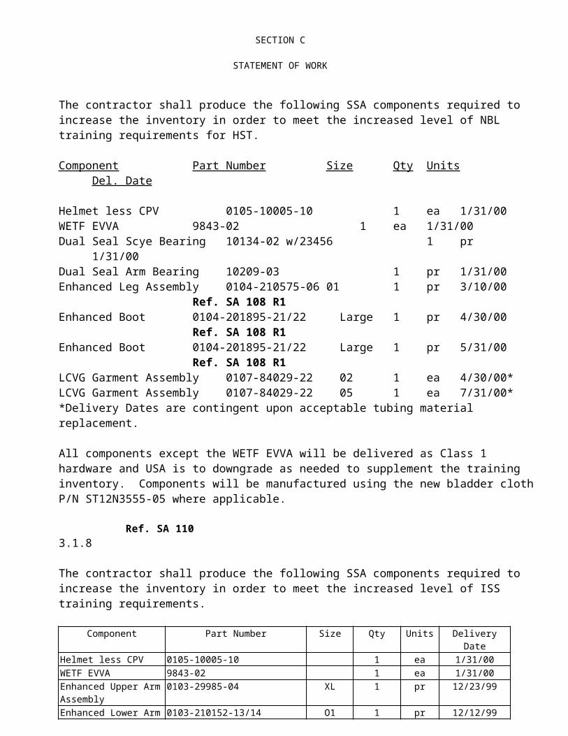
SECTION C
STATEMENT OF WORKfacility interfaces; (3) the planned ground and space environment; (4) the supporting equipment; (5) task sequence; (6) the regulatory safety and health requirements; and (7) the potential for human error. The contractor shall report and investigate accidents resulting in damage to Government property or injuries to NASA or other non-contractor personnel, to include assessments of accident impacts to cost, schedule and mission performance, and remedial and corrective actions performed. The approach shall cover operations both by the contractor and by other Government and non-Government organizations within operational facilities controlled by the contractor. The approach shall include provisions for program approval, by the appropriate Government interface, of risk associated with hazards not eliminated or controlled. The approach and results shall be documented by the contractor and auditable by the Government.
The contractor shall provide summary data on accidents in accordance with Data Requirement Description No. 25.
The contractor shall support the NASA Managed Safety Program for Pressure Vessels and Pressure Systems in accordance with NMI 1710.3, NHB 1700.6, KHB 1710.15, JHB1710, MHB1710.10, & NASA/SSC Operations Procedure 83-1. This support shall be provided in accordance with Data Requirement Descriptions No. 26 and No. 27.
5.2 Mission Assurance
The contractor shall develop and implement a mission assurance approach which will support the objective of ensuring that the Shuttle and ISS programs are provided with reliable hardware, incorporating optimized maintenance features. The approach will include but not be limited to: assessments of reliability and maintainability performance against baseline allocations; preparation, maintenance and control of reliability assessments such as Failure Modes and Effects Analyses (FMEAs), Critical Items Lists (CIL’s), and assessments of materials and parts in support of operational integrity. This approach shall include fight hardware experience and contractor analytical assessments. Reliability assessments shall identify critical items and the operational impacts of hardware failure modes. The approach shall be documented by the contractor and auditable by the Government. The FMEA and CIL documentation shall be prepared in accordance with Data Requirement Description No. 28.
A Reliability And Maintainability Plan shall be submitted in accordance with Data Requirement Description No. 29.
Electrical, Electronic and Electromechanical Parts (EEE) selection, use, test and control shall be conducted in accordance with Data Requirement Description No. 30.

SECTION C
STATEMENT OF WORKThe contractor shall support program development efforts, as required, to develop system reliability, availability and maintainability requirements and assess the designs to assure that the requirements are met.
5.3 Product Assurance
5.3.1 Quality Assurance
The contractor shall develop and implement an approach which describes the establishment and maintenance of a quality management system in accordance with ISO 9001 requirements which includes a formal Materials Review Broad (MRB) review process. This approach shall show continuous and measurable improvement, and shall be documented by the contractor. The field support group, while performing tasks on-site at JSC shall comply with all JSC requirements, including JHB 5335.1. Reference Data Requirement Description No. 31.
5.3.2 Product and Service Quality
The contractor shall collect and compile information derived from empirical data (test results, analysis reports, inspection records, delivery logs, etc.) to demonstrate that the products and services delivered to the Government are in compliance with the requirements and specifications as specified in this contract. The delivery of the compliance information shall be at the request of the Government.
The contractor shall provide and maintain, for those items that the contractor has custody, an Acceptance Data Package in accordance with SN-S-0008 and SN-C-0007 for hardware/software delivery or transfer to the Government. Reference Data Requirement Description No. 32.
The contractor shall provide for the identification, reporting, and elimination/disposition of non-conformances / problems / anomalies/failure analysis in accordance with NSTS 07700 and NSTS 08126; Problem Reporting and Corrective Action (PRACA) requirements, as appropriate, including recording anomalous system performance and material conditions identified, providing rationale for resolution, the remedial action performed, the recurrence control and corrective actions taken to preclude recurrence, and determining the effectiveness of corrective actions. The contractor shall provide access to PRACA documentation, data, databases, analysis, and related information to the Government. The contractor shall create and sustain an open communication with employees and subcontractors to identify, track, and resolve non-conformances / problems/ anomalies including close calls. The contractor shall have a data system that allows the Government real-time access to this problem data. Initially, the contractor shall use the existing PRACA system and may propose improvements to the system unless an alternate system and a transition

SECTION C
STATEMENT OF WORKfrom PRACA is approved by NASA. The contractor shall provide for appropriate Government insight, into the disposition of non-conformances / problems / anomalies, including notifying the Government of the occurrence and, as appropriate, obtaining Government approval of the disposition as specified in SOW section 1.1.4. The contractor shall initiate (including requesting Government approval) action to change or eliminate requirements that non-conformance data analysis indicates are unreasonable or unnecessary, and to improve or change processes which produce products or services that fail to meet requirements.
5.3.3 Process Quality
The contractor shall identify and plan the production, installation, and servicing processes which directly affect quality, safety, or reliability and shall ensure that these processes are carried out under controlled conditions. Controlled conditions may include but are not limited to; documented procedures, monitoring of suitable process parameters, and use of workmanship standards.
5.4 Waivers or Deviations
All waivers or deviations granted under NAS 9-17873 shall apply to this contract unless superseded by the requirements contained herein. In addition to the requirements stated above, the contractor’s quality assurance program shall comply with the requirements of NASA publication NHB 5300.4 (ID-2), with the following exceptions:
A. Chapter 2
1. Paragraph ID200, part 2 - Delete
2. Paragraph ID200, part 3n - Delete
B. Chapter 3
1. Paragraph ID300, part 2 - Reliability Plan:
Delete the requirements of subparagraph 2b.
C. Chapter 5:
ID503.4c Interrelated Source Inspection DeletedID503.9e Unified Survey Activities DeletedID503.10 Coordination of Contractor's Deleted
Procurement and Source Inspection and TestID505.8 Walk Through/Shakedown Inspection DeletedID505.9 Quality Assurance Designees Deleted
SECTION C
STATEMENT OF WORKID505.10 Vehicle Access Control DeletedID505.11 GSE Access Control DeletedID510 Sampling Plans, Statistical Deleted
Planning and Analysis
SECTION D
PACKAGING AND MARKING
D.1 LISTING OF CLAUSES INCORPORATED BY REFERENCE
NOTICE: The following solicitation provisions and/or contract clauses pertinent to this section are hereby incorporated by reference:
I. Federal Acquisition Regulation (48 CFR Chapter 1) -
No Far By-Reference Clauses In Section D
II. NASA Federal Acquisition Regulation (48 CFR Chapter 18) -
No NASA By-Reference Clauses In Section D
D. 2 PACKAGING AND MARKING
Preservation, packaging, packing, and marking for shipment shall be in accordance with NASA Handbook, NHB 6000.1, current edition as of the effective date of contract.
Shipment of hardware to Depot Stores located at Hamilton Standard will be according to Hamilton Standard Space and Sea Systems Procedure SVP 112, latest revision as controlled by Hamilton Standard records, packaging of visually clean and precision clean component. Hamilton Standard will package in accordance with MIL-STD-129L (Ref. SA 285) and MIL-STD-130F as referenced in Section J-12 Applicable Documents
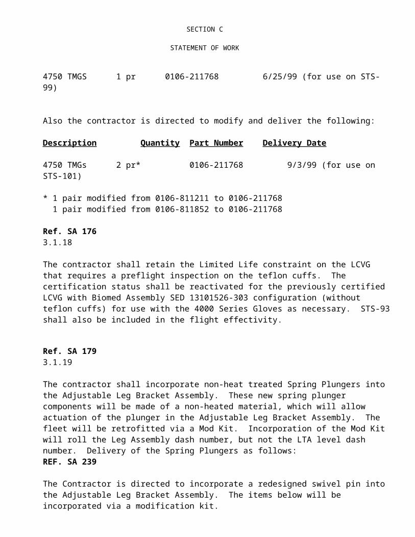
SECTION E
INSPECTION AND ACCEPTANCE
E.1 LISTING OF CLAUSES INCORPORATED BY REFERENCE
NOTICE: The following solicitation provisions and/or contract clauses pertinent to this section are hereby incorporated by reference:
I. FEDERAL ACQUISITION REGULATION (48 CFR CHAPTER 1) -
52.246-3 Inspection of Supplies-Cost Reimbursement (Apr 1984)
II. NASA FEDERAL ACQUISITION REGULATION (48 CFR CHAPTER 18) -
18-52.246-72 Material Inspection and Report (Jun 1995)
E.2 PRELIMINARY INSPECTION AT SOURCE AND FINAL INSPECTION AND ACCEPTANCE AT DESTINATION
(A) HARDWARE SHIPPED TO NASA JSC:
PRELIMINARY INSPECTION FOR COMPLIANCE WITH THE CONTRACT SPECIFICATIONS AND REQUIREMENTS MAY BE PERFORMED AT ORIGIN BY AN AUTHORIZED REPRESENTATION OF THE GOVERNMENT, AND FINAL INSPECTION AND ACCEPTANCE WILL BE PERFORMED AT NASA LYNDON B. JOHNSON SPACE CENTER BY THE CONTRACTING OFFICER OR HIS AUTHORIZED REPRESENTATIVE. UNLESS OTHERWISE SPECIFIED ELSEWHERE IN THIS CONTRACT, THE TECHNICAL MANAGER IS THE ONLY REPRESENTATIVE OF THE CONTRACTING OFFICER FOR FINAL INSPECTION AND ACCEPTANCE.
(B) HARDWARE SHIPPED TO PLACES OTHER THAN NASA JSC:
INSPECTION AND FINAL ACCEPTANCE SHALL BE PERFORMED AT SOURCE BY THE AUTHORIZED GOVERNMENT REPRESENTATIVE.
(C) HARDWARE SHIPPED IN PLACE TO BONDED STORES AT HAMILTON STANDARD:
INSPECTION AND FINAL ACCEPTANCE SHALL BE PERFORMED AT SOURCE BY THE AUTHORIZED GOVERNMENT REPRESENTATIVE.
(D) HARDWARE SHIPPED TO JSC BUILDING 7 AND BUILDING 32 BOND ROOMS
INSPECTION AND FINAL ACCEPTANCE SHALL BE PERFORMED AT SOURCE BY THE AUTHORIZED GOVERNMENT REPRESENTATIVE.
(E) HARDWARE SHIPPED FROM ILC, DOVER TO HSMS
INSPECTION SHALL BE PERFORMED AT SOURCE BY THE AUTHORIZED DCMC REPRESENTATIVE, AND ACCEPTANCE WILL BE PERFORMED AT DESTINATION BY HSMS AND NASA.
Ref. Sa 31

SECTION E
INSPECTION AND ACCEPTANCE
(f) Class I HUTs shipped from ILC, Dover to Boeing
Inspection and final acceptance shall be performed at ILC by an authorized Government representative.
E.3 EVALUATION AND ACCEPTANCE
FINAL EVALUATION AND ACCEPTANCE OF THE DATA SET FORTH IN SECTION J-1, DATA REQUIREMENTS DESCRIPTION SHALL BE ACCOMPLISHED BY THE CONTRACTING OFFICER OR HIS DULY AUTHORIZED REPRESENTATIVE AT NASA JSC. UNLESS OTHERWISE SPECIFIED IN THIS CONTRACT, THE TECHNICAL MANAGER IS THE ONLY AUTHORIZED REPRESENTATIVE OF THE CONTRACTING OFFICER FOR THE PURPOSE OF THIS ARTICLE.
E.4 QUALITY ASSURANCE SURVEILLANCE PLAN (JSC 52.246-93) (JULY 1996)
A QUALITY ASSURANCE SURVEILLANCE PLAN (QASP) WILL BE DEVELOPED AND IMPLEMENTED BY THE CONTRACTING OFFICER'S TECHNICAL REPRESENTATIVE (COTR) AS A PART OF THE CONTRACT ADMINISTRATION AND MONITORING ACTIVITIES CONDUCTED TO ASSURE THAT THE GOVERNMENT RECEIVES PRODUCTS AND SERVICES THAT CONFORM TO CONTRACT REQUIREMENTS. THE NATURE AND EXTENT OF QUALITY ASSURANCE SURVEILLANCE CONTEMPLATED IN THIS PLAN WILL BE BASED, IN PART, ON THE SPECIFIC CONTENT OF THE CONTRACTOR'S QUALITY PLAN (INCLUDED IN SECTION J).
(END OF CLAUSE)

SECTION F
DELIVERIES OR PERFORMANCE
F.1 LISTING OF CLAUSES INCORPORATED BY REFERENCE
NOTICE: The following solicitation provisions and/or contract clauses pertinent to this section are hereby incorporated by reference:
I. FEDERAL ACQUISITION REGULATION (48 CFR CHAPTER 1) -
52.247-29 F.O.B. Origin (Jun 1988)
II. NASA FEDERAL ACQUISITION REGULATION (48 CFR CHAPTER 18) -
No NASA By-Reference clauses in Section F
F. 2 OPTION TO EXTEND COMPLETION DATE (JSC 52.217-90) (OCT 1996)
The Government may require the contractor to continue to perform services under this contract. The CO may exercise this option by issuance of a unilateral contract modification 30 days or more before the end of the contract completion date set forth in Section F. Should the option be exercised, the resultant contract will include all terms and conditions of the basic contract as it exists immediately prior to the exercise of the option, except for the following changes:
EXERCISED (REF. SA
324)OPTION 1(GFY 02)
OPTION 2(GFY 03)
OPTION 3(GFY 04)
ESTIMATED COST AND FEE Ref. SA 193 (Option 1 added to Baseline $s
per SA 324)
Ref. SA 260
Estimated Target Cost* $11,392,067
$11,610,420
$11,495,465
Target Incentive Fee $825,665 $837,404 $833,753
Maximum Available Award Fee $206,416
$209,351 $208,438
Maximum Fee at Target Cost
Minimum Incentive Fee*
Maximum Total Fee**
$1,032,081
$147,985
$1,596,815
$1,046,755
$147,012
$1,412791
$1,042,191
$149,880
$1,612,084
Total Option Values $12,424,148
$12,657,175
$12,537,656
* Subject to the award fee performance gate included under Section J-4, Performance Evaluation (Fee) Plan** Includes all fees payable under the contract which are not to exceed 15% of total estimated cost less cost of money

SECTION F
DELIVERIES OR PERFORMANCERef. SA 324The period of applicability of Clause 52.245-7 Use of Government Facilities is hereby extended to September 30, 2003. (Ref. SA 400)
Ref. SA 1883.2.2a Item 386 DCM Wiring and Electronic Assemblies (Option)The Contractor shall refurbish one (1) DCM Electronic Assemblies to support the refurbishment of a DCM (2004) scheduled to be completed by 6/30/02. NASA will provide DCM GFE at least 112 days prior to scheduled delivery date.
Ref. CCO 230F.2 Option to Extend Completion Date (JSC 52.2217-90) add the following to Option Period 1:
Section J-6 Hardware Quantities and Delivery Schedules
"0104-81235-01-01Rest/Blad. Short 4 -11/26/01
0104-812454-01-01 TMG
0104-812355-01-02 Rest/Blad Long 4 -2/4/02
0104-812454-01-02 TMG
0104-812355-01-01 Rest/Blad Short 4 -4/19/02
0104-812454-01-01 TMG
0104-812355-01-02 Rest/Blad. Long 4 -7/1/02
0104-812454-01-02 TMG
0104-81235-01-01Rest/Blad. Short 5 -9/27/02
0104-812454-01-01 TMG
Totals 33 4
Ref. SA 318EMU Small Suit SSA Development and Certification Program
The contractor shall complete EMU Small Suit SSA Development Program Certification by 8/25/03.
The following SSA hardware shall be delivered to CTSD on or before 1/29/03.

SECTION F
DELIVERIES OR PERFORMANCE
NEED PART NUMBERSDescription P/N QTYUpper Arm (Class III) TBD 1 pairLower Arm (Class III) TBD 1 pairSmall Arm Bearing (Class III) TBD 1 pairBoot Sizing Insert (Class III) TBD 1 pairCanted Waist (Class III) TBD 1 eachLCVG (Class III) TBD 1 each
Ref SA 319EMU Small Suit HUT Development and Certification ProgramThe contractor shall deliver a Class III Small Planar HUT (P/N 0102-110102-01) for training purposes on or before 6/19/03.The contractor shall complete certification 8/25/03**
** Certification closure is based on parallel certification testing with the first and second ClassIII Small HUTs.
Ref. SA 321 Upgrade of PLSS 1001 and SOP 1020The deliverables are as follows:
Item Delivery Date (On or Before)
PLSS 1001 Class II EMUM 2/28/03
PLSS 1001 (SV26098) 2/28/03 NASA JSC Building 7, Houston, TX
SOP 1020 (SV799045-00-02)* 4/11/03 USA 16850 Buccaneer Lane, Houston, TX
SOP Cover (SV769988-3) 11/16/01HSSSI Bonded Stores, Windsor Locks, CT
Primary Regulator (SV778873-14) 12/19/02HSSSI Bonded Stores, Windsor Locks, CTWill be used in support of certification Shearplate Build after Delivery
* Part Number to be modified pending incorporation of new Item 215 Pressure Transducercurrently under certification
3. The Following Government Furnished Property will be provided to the contractor:

SECTION F
DELIVERIES OR PERFORMANCEItem Due Date
PLSS Shipping Container (PK8918)with shipping fixture (SV767700CT002) 01/28/03
SOP Shipping Container (PK8923)with shipping fixture (SV767710CT001) 03/11/03
Item 122 IR CO2 Sensor* 11/16/02New Item 215 Transducer (SV823476) Bonded Stores
(Utilized to build Item 200 SOP S/N 1020)Item 210 SOP Bottles (2) and Cover Bonded StoresItems 112, 114, 128, 132, 137, 138 & 171 as required
* Item 122 IR CO2 Sensor will be removed and returned to USA in the event of urgent field need as determined by the NASA
Ref. SA 352Phase VI ImplementationF.2 Option to Extend Completion Date (JSC 52.2217-90) add the following to OptionPeriod 2:
The deliverables shall be delivered during FY 03 are as follows:
DESCRIPTION QTYPhase VI Customization 8 prOf these 8 prs the following crewmember has been identified:Maclean 6MN 12 TBD
Fuglesand 6FG 12 TBD
Phase VI Production Flight Gloves 51 prPhase VI TMGs 51 prPhase VI Bladders 9 pr
Ref. SA 365 F.2 Option to Extend Completion Date (JSC 52.2217-90) add the following to Option Period 2:
SECTION J-6 / DELIVERABLES
Refurbishment of Item I-171/172 shall be delivered on or before November 11, 2002. GFE required by March 21, 2002.
Ref. SA 352Phase VI Implementation

SECTION F
DELIVERIES OR PERFORMANCEF.2 Option to Extend Completion Date (JSC 52.2217-90) add the following to OptionPeriod 3:
The deliverables shall be delivered during FY 04 are as follows:
DESCRIPTION QTYPhase VI Customization 8 prPhase VI Production Flight Gloves 18 prPhase VI TMGs 25 prPhase VI Bladders 8 pr
SA 380 Deferral Mod.
(Reference SA 352, Phase VI Implementation)
The following Quantities are revised:
FROM: FY 03
PVU Gloves 8Flight Gloves 51TMGs 51Bladders 9
TO:FY 03
PVU Gloves 12Flight Gloves 37TMGs 28Bladders 9
SA 380Deferral Mod.
. J-5 Program Provisioning, Supplier Supportability and Technology Obsolescence
(Reference PPDO 00-2.2.5A-201 and R1 DCM/FPS Electronic Parts Procurement)
The following effort is deferred from FY 01 to FY 03:
Base:

SECTION F
DELIVERIES OR PERFORMANCE Re-tin leads on parts that have been in HSSSI Stores for more than three (3)
years Update operation sheets for the CWS Assemble, test, process and final inspect two (2) sets of CWS PC board
assemblies Double bag and place PC board assemblies in HSSSI Stores
R1:
Prepare summary Engineering Change information
Option 3Ref. SA 380Deferral Mod.
(Reference SA 352, Phase VI Implementation)
The following Quantities are revised:
FROM: FY 04
PVU Gloves 8Flight Gloves 18TMGs 25Bladders 8
TO:FY 04
PVU GlovesFlight Gloves 48TMGs 51Bladders 15
Ref. SA 358
Pressure Transducer I-215 14 April 21, 2003
Certification closure by October 24, 2002.
Ref. SA 262
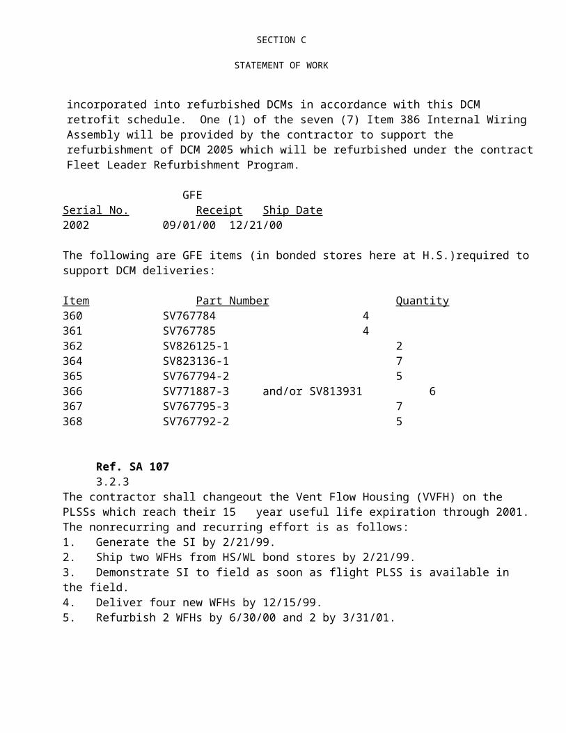
SECTION F
DELIVERIES OR PERFORMANCEF.2 Option to Extend Completion Date (JSC 52.2217-90) add the following to Option Period 2:
Hardware Deliveries/Section J-6
1 Malfunction Simulator, P/N TBD, delivered to MOD on or before 1/31/03**
2 Acceptance Test Rigs, P/N TBD, delivered to USA on or before 2/28/03
**These rigs will utilize the 2 sets of boards assembled and tested during the
development program and assumes boards will be functional prior to installation
into these rigs
OPTION 1 OPTION 2 OPTION 3 (GFY 02) (GFY 03) (GFY 04)
Clause F.5 - Completion of Work amended to read: 9/30/02 9/30/03 9/30/04
Clause B.3 - Estimated Program Provisioning Cost is increased by TBD TBD TBD
52.245-7--Use of Gov’t Facilities Extended to: 9/30/02 9/30/03 9/30/04
(End of clause)
SA 377N=12F.2 Option to Extend Completion Date (JSC 52.2217-90) add the following to Option
Period 2:Section J-6 Hardware Quantities and Delivery Schedules Deliverables:
ITEM PART NO.
DESCRIPTIONQTY
ON OR BEFORE DELIVERY DATE
132 SV767793-7 Feedwater Supply Pressure Sensor 4 9/30/03
137 SV767660-10 Feedwater Shutoff Valve 2 12/31/02138 SV767793-8 Feedwater Pressure Sensor 8 9/30/03139 SV792503-1 Temperature Sensor Harness 4 9/30/03146 SV787036-11 Positive Pressure Relief Valve 1 9/30/03
171 SV784982-3 Solenoid Valve 54
12/31/029/30/03

SECTION F
DELIVERIES OR PERFORMANCE213 SV799042-3 Secondary O2 Pressure Control
Module1 3/31/03
(HS Bonded)411 SV778865-4 Oxygen High Pressure Line 4 9/30/03
412 SV771722-12 Potable Line Hose (Sets) 2 9/30/03
418 SV771717-7 Condensate Water Regulator 66
3/30/039/30/03
419 SV772190-6 Regulator, Water Supply Pressure 55
3/30/039/30/03
425* SV771763-3 SCU Electrical Harness 1233
10/31/0211/30/021/31/039/30/03
SECTION J-7 Hardware Refurbishment Schedule:
ITEM NO PART NO. DESCRIPTION
MAINTENANCE DESCRIPTION QTY
GFE RECEIPT
DATE FROM USA*
ON OR BEFORE DELIVERY DATE
100 SV799100 Primary Life Support System
20 to 30 Year Life Extension Refurbishment
1(FL) Received 4/30/03
115 SV824133 Shear Plate Assembly
20 to 30 Year Life Extension Refurbishment
1111
05/06/0201/02/0305/20/0211/04/02
01/31/0305/30/0304/15/0310/31/03
123 SV787994 Fan/Pump/Separator Assembly
15 to 25 Year Life Extension Refurbishment
1 09/23/02 09/30/03
131 SV824131 Primary Water Tank
20 to 30 Year Life Extension Refurbishment
1(FL) Received 4/30/03
200 SV799045 Secondary Oxygen Pack (SOP)
Component Replacements 22
02/01/0306/01/03
05/31/0309/30/03
350 SV792291 DCM Electronics Assembly
15 to 25 Year Life Extension Refurbishment
11
09/23/0205/22/03
05/30/0309/30/03
470 SV767680 Airlock Adapter Plate (AAP)
20 to 30 Year Life Extension Refurbishment
1 09/23/02 02/02/03
ITEM NO PART NO. DESCRIPTION
MAINTENANCE DESCRIPTION QTY
GFE RECEIPT
DATE FROM USA*
ON OR BEFORE DELIVERY DATE
139/140
SV805280 Sublimator and Harness Assembly
20 to 25 Year Life Extension Refurbishment
1 09/23/02 09/30/03
123 SV787994 Fan/Pump/Separator Assembly
25 to 35 Year Life Extension Refurbishment
1 09/23/02 09/30/03
113 SV778873 Primary O2 Pressure Regulator
20 to 30 Year Life Extension Refurbishment
1111
See Note (1) See Note (1)
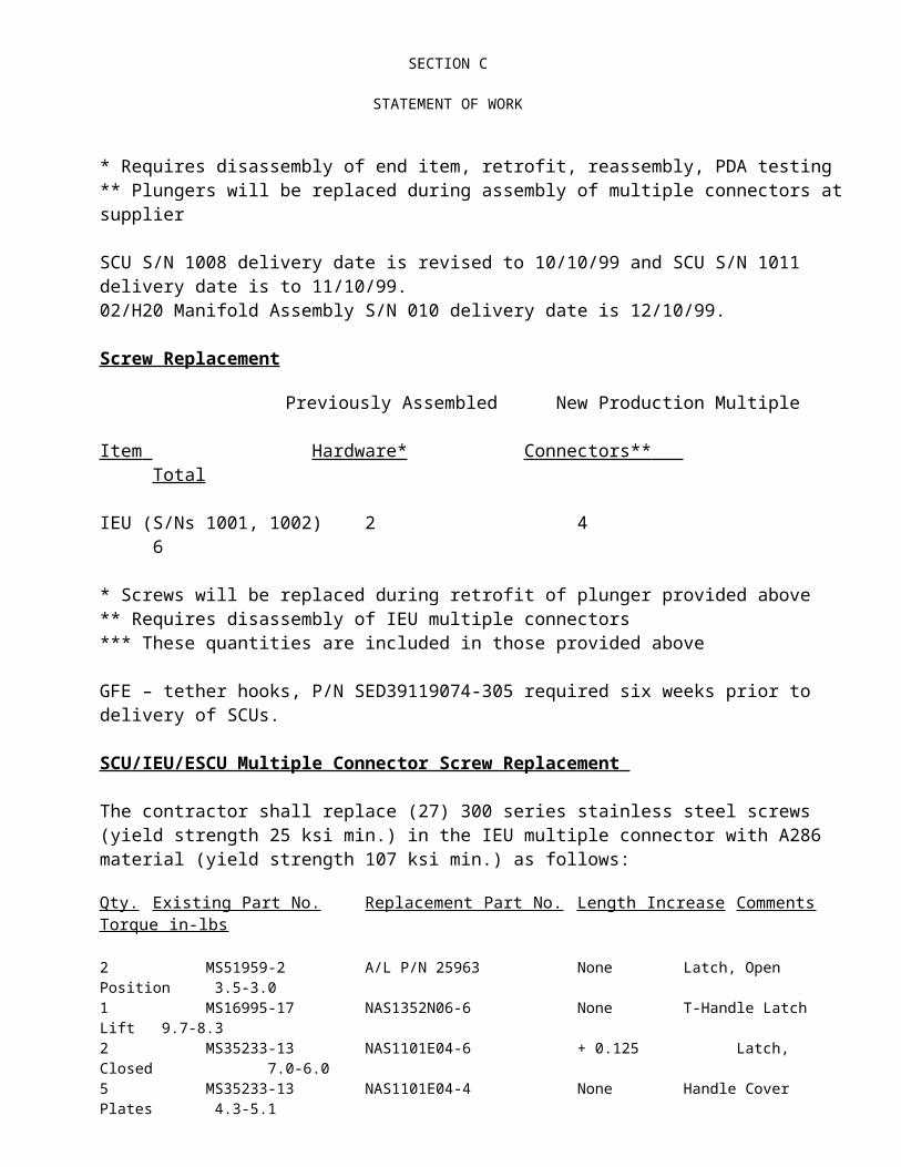
SECTION F
DELIVERIES OR PERFORMANCE3. F.2 Option to Extend Completion Date (JSC 52.2217-90) add the
following to OptionPeriod 3:
Section J-6 Hardware Quantities and Delivery SchedulesDeliverables:
ITEM PART NO.
DESCRIPTIONQTY
ON OR BEFORE DELIVERY DATE
125 SV769480-4 Pitot Actuated Valve 3 9/30/04
127 SV805180-1 Pump Inlet Filter5 9/30/04
135 SV769404-7 Feedwater Relief Valve 3 9/30/04139 SV792503-1 Temperature Sensor Harness 10 9/30/04143 SV769406-2 Water Check Valve 1 9/30/04153* SV789153-6 Caution and Warning Harness 1
33/31/049/30/04
171 SV784982-3 Solenoid Valve 5 9/30/04311 SV767706-6 DCM Suit Pressure Gage 3 9/30/04410 SV778872-24 SCU Common Multiple Connector 2 9/30/04419 SV772190-6 Regulator, Water Supply Pressure 3 9/30/04425* SV771763-3 SCU Electrical Harness 1 9/30/04
* These harnesses are being redesigned, the P/Ns will change accordingly.
3. SECTION J-7 Hardware Refurbishment Schedule:
Add the following hardware :
ITEM NO PART NO. DESCRIPTION
MAINTENANCE DESCRIPTION
QTY
GFE RECEIPT
DATE FROM USA*
ON OR BEFORE DELIVERY DATE
113 SV778873 Primary O2 Pressure Regulator
20 to 30 Year Life Extension Refurbishment
11
See Note (1) See Note (1)
115 SV824133 Shear Plate Assembly
20 to 30 Year Life Extension Refurbishment
1111
04/01/0307/01/0312/01/0309/01/03
01/30/0405/31/0409/30/0407/30/04
123 SV787994 Fan/Pump/Separator Assembly
25 to 35 Year Life Extension Refurbishment
11
05/24/0309/23/03
05/31/0409/30/04
139/140
SV805280 Sublimator and Harness Assembly
25 to 30 Year Life Extension Refurbishment
1 09/23/03 09/30/04

SECTION F
DELIVERIES OR PERFORMANCE200 SV799045 Secondary Oxygen
Pack (SOP)Component Replacements 2
22
10/01/0302/01/0406/01/04
01/31/0405/31/0409/30/04
350 SV792291 DCM Electronics Assembly
15 to 25 Year Life Extension Refurbishment
1 01/22/04 05/30/04
420 SV778504 Filter Assembly, Oxygen and Orifice
15 to 25 Year Life Extension Refurbishment
1 05/24/04 09/30/04
470 SV767680 Airlock Adapter Plate (AAP)
20 to 30 Year Life Extension Refurbishment
1 09/23/03 02/02/04
(1) An I-113 refurbishment is shown as a separate line item task but is included as part of an I-115 Refurbishment. The I-113 is removed from an I-115 Shear Plate received as GFE from USA. The I-113 is then sent to the supplier for refurbishment, returned, and delivered to HSSSI Stores to await re-assembly to a refurbished I-115 for final delivery to USA.
*The above GFE shall not be assembled together, except for Items 100/131. All GFE Shall be complete end items Note: All refurbishment/replacement effort is based on the life extension report. Any EEE parts issues with technology obsolescence shall be within the program provisionin g section of the contract.
SA 378H7044R3 ECWSF.2 Option to Extend Completion Date (JSC 52.2217-90) add the following to Option
Period 2:Section J-6 Hardware Quantities and Delivery SchedulesDeliverables:
Qty. Part Number Item Delivery Date On or before
Cert Closure Certification closure of the Enhanced Caution & Warning System
9/30/03
1 SV827600-1 Delivery of the certification Enhanced Caution & Warning System unit
9/30/03
1 SV827600-1 Enhanced Caution & Warning System (Flight)*
7/31/03
Cert Closure Certification closure of the I-156 Harness
9/30/03
1 SV827765-1 Delivery of the certified I-156 Harnesses
9/30/03
1 SV827765-1 I-156 Harnesses (Flight)* 7/31/032 SV827765-1 I-156 Harnesses (Flight) 9/30/03
*Ship to CTSD with Open Certification
Ref. SA 396CCBD H7221 EMU SSA Combination Purge Valve (CPV) Gasket Replacement and Flow Test Performance

SECTION F
DELIVERIES OR PERFORMANCE
The contractor is directed to obtain, evaluate, certify, and incorporate a new silicone base material used to manufacture CPV gaskets by completing the following activities on or before April 03,2003. 1. Complete the performance of CPV/Helmet leak testing with gaskets made from the
proposed replacement material. 2. Conduct MATCO testing. 3. Revise Air-Lock CPV Assembly Drawings and gasket drawings to reflect
incorporation of new gaskets. 4. Generate certification documentation including ECO’s, CIARS, and CERT report.
In addition, the contractor is directed to revise the Helmet S/AD Part ii and PDA documents to allow Air-Lock Inc. to perform the same CPV flow test that NASA/JSC used to perform to verify the CPV bore diameter. The Helmet S/AD part II and PDA documents, as well as the Air-Lock acceptance documents will be revised to reflect this change. There will be a no certification impact CIARS processed with the flow test ECO (021-0227).
F.2 Option to Extend Completion Date (JSC 52.2217-90) add the following to Option
Period 3:
Section J-6 Hardware Quantities and Delivery SchedulesDeliverables:
Qty. Part Number Item Delivery Date On or before
2 SV827600-1 Enhanced Caution & Warning System (Flight)
10/15/03
3 SV827600-1 Enhanced Caution & Warning System (Flight)
2/15/04
3 SV827600-1 Enhanced Caution & Warning System (Flight)
6/15/04
3 SV827765-1 I-156 Harnesses (Flight) 1/31/043 SV827765-1 I-156 Harnesses (Flight) 5/31/043 SV827765-1 I-156 Harnesses (Flight) 9/30/04
F. 3 STOP - WORK ORDER (52.242-15) (AUG 1989)--ALTERNATE I (APR 1984)
(a) The Contracting Officer may, at any time, by written order to the Contractor, require the Contractor to stop all, or any part, of the work called for by this contract for a period of 90 days after the order is delivered to the Contractor, and for any further period to which the parties may agree. The order shall be specifically identified as a stop-work order issued under this clause.

SECTION F
DELIVERIES OR PERFORMANCEUpon receipt of the order, the Contractor shall immediately comply with its terms and take all reasonable steps to minimize the incurrence of costs allocable to the work covered by the order during the period of work stoppage. Within a period of 90 days after a stop-work is delivered to the Contractor, or within any extension of that period to which the parties shall have agreed, theContracting Officer shall either--
(1) Cancel the stop-work order; or
(2) Terminate the work covered by the order as provided in the Default, or the Termination for Convenience of the Government, clause of this contract.
(b) If a stop-work order issued under this clause is canceled or the period of the order or any extension thereof expires, the Contractor shall resume work. The Contracting Officer shall make an equitable adjustment in the delivery schedule or contract price, or both, and the contract shall be modified, in writing, accordingly, if--
(1) The stop-work order results in an increase in the time required for, or in the Contractor's cost properly allocable to, the performance of any part of this contract; and
(2) The Contractor asserts its right to the adjustment within 30 days after the end of the period of work stoppage; provided, that, if the Contracting Officer decides the facts justify the action, the Contracting Officer may receive and act upon the claim submitted at any time before final payment under this contract.
(c) If a stop-work order is not canceled and the work covered by the order is terminated for the convenience of the Government, the Contracting Officer shall allow reasonable costs resulting from the stop-work order in arriving at the termination settlement.
(d) If a stop-work order is not canceled and the work covered by the order is terminated for default, the Contracting Officer shall allow, by equitable adjustment or otherwise, reasonable costs resulting from the stop-work order.
(End of clause)
F.4 DELIVERY SCHEDULE
All items required to be furnished by this contract shall be delivered in accordance with:
Section J-1 - Data Requirements List Section J-6 - Hardware Quantities and Delivery Schedules Section J-7 - Hardware Refurbishment Quantities and Schedules Section J-13 - NAS 9-17873 Carry-Over Effort
F.5 COMPLETION OF WORK (JSC 52.212.95) (Sep 1988)
All work required under this contract, including submission of all reports shall be completed on or before September 30, 2003 (Ref. SA 400) (Ref. SA 324).
F.6 SHIPMENT BY GOVERNMENT BILLS OF LADING (NASA 18-52.247-73) (MARCH 1997)

SECTION F
DELIVERIES OR PERFORMANCE(a) The Contractor shall ship items deliverable under this contract, if the transportation cost per shipment exceeds $100, by Government bills of lading (GBLs). At least 15 days before shipment, the Contractor shall request in writing GBLs from: JSC Transportation Officer, Mail Code JB7, Attention: Julie Pate, NASA Lyndon B. Johnson Space Center, Houston, Texas 77058. If time is limited, requests may be by telephone: 713-483-6528. Requests for GBLs shall include the following information.
(1) Item identification/ description.
(2) Origin and destination.
(3) Individual and total weights.
(4) Dimensions and total cubic footage.
(5) Total number of pieces.
(6) Total dollar value.
(7) Other pertinent data.
(b) The Contractor shall prepay transportation charges of $100 or less per shipment. The Government shall reimburse the contractor for these charges if they are added to the invoice as a separate line item supported by the paid freight receipts. If paid receipts in support of the invoice are not obtainable,a statement as described below must be completed, signed by an authorized company representative, and attached to the invoice. "I certify that the shipments identified below have been made, transportation charges have been paid by (company name), and paid freight or comparable receipts are not obtainable.
Contract or Order Number: _____________________
Destination: _________________________________"
(End of clause)
F.7 SHIPPING INSTRUCTIONS (JSC 52.247-94) (APR 1997)
(a) All documentation shall be shipped to the addresses cited in Section J-1 Data Requirements List.
(b) Shipment of hardware end items, except Customer Returned Materials (CRM) and CTSD support items shall be as follows:
Ref. SA 94Delivery Location: United Space Alliance, LLC
16850 Buccaneer Land Houston, TX 77058
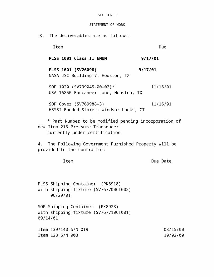
SECTION F
DELIVERIES OR PERFORMANCE(c) The contractor must prepare DD Form 250, Material Inspection and Receiving Report, in an original and two copies, for each shipment (excluding reports and documentation) made under the terms of this contract. Block 19, "Unit Price," and Block 20 "Amount," of the DD Form 250 must be completed. Where the form is not used as an invoice for payment purposes, the amounts entered may be the Contractor's best estimate.
(d) Address the original for each data pack, one copy to ND32, and one copy JF5.
(e) Delivery location for all CRM shall be defined by the Hamilton Standard CRM Administrator.
(f) Ship CTSD support items to JSC Building 7, Bond Room. Support items include EMU equipment used by CTSD to support EMU development, certification, and EVA procedures development testing:
Parcel Post Shipments and Freight Shipments
Ship to: Transportation Officer, Building 421NASA Johnson Space Center2101 NASA Road 1Houston, TX 77058-3696
Mark for: Accountable Property Officer 807402Mark with: Contract Number: NAS 9-97150For reissue to: ______________________________________
(Name) (Mail Code) (Bldg.) (Rm)
(End of clause)
F.8 FLIGHT ITEM (JSC 52.247-95) (SEP 1989)
Block 16 of each DD Form 250 prepared for hardware or equipment to be shipped under this contract must be annotated as follows in 1/4-inch letters or larger by handprinting or rubber stamp:
"THIS IS A FLIGHT ITEM" or "THIS IS MISSION ESSENTIAL GROUND SUPPORT EQUIPMENT," as applicable.

SECTION G
CONTRACT ADMINISTRATION DATAG.1 LISTING OF CLAUSES INCORPORATED BY REFERENCE
The following clauses are hereby incorporated by reference:
18-52.227-70 New Technology (Jul 1995)18-52.227-71 Request for Waiver of Rights to Inventions (Apr 1984)18-52.227-72 Designation of New Technology Representative and Patent Representative (JUL 1997); in paragraph (a) add: NASA Lyndon B. Johnson Space Center, HA/ Technology Transfer and Commercialization Office, Houston, TX 77058; and
HA/Patent (same address)18.52.242-73 NASA Contractor Financial Management Reporting Jul 1997)18-52.245-71 Installation-Accountable Government Property (Jul 1997)18.52.245-73 Financial Reporting Of NASA Property In The Custody Of Contractors (Sep 1996)
G.2 SUBMISSION OF INVOICES (JSC 52.232-90) (OCT 1993)
Invoices shall be prepared and submitted in quadruplicate unless otherwise specified. Invoices shall contain the following information as applicable: contract and order number, item numbers, description of supplies or services, sizes, quantities, unit prices, and extended totals. Invoices shall be submitted to:
1. Cost Vouchers, forwarded not more often than once every two (2) weeks:
Defense Contract Audit Agency (DCAA)Northeastern RegionHamilton Standard DivisionWindsor Locks, Connecticut 06096-0463
2. Fee Vouchers, forwarded not more often than once a month.
NASA Lyndon B. Johnson Space CenterBL3 / EVA Business Management OfficeAttn: Robin P. Chapman Houston, Texas 77058
3. Copy of cost voucher, forwarded by DCAA:
NASA Lyndon B. Johnson Space Center BL3 / EVA Business Management Office
Attn: Robin P. ChapmanHouston, Texas 77058

SECTION G
CONTRACT ADMINISTRATION DATA
4. For payment:
NASA Lyndon B. Johnson Space CenterLF2 / Commercial Accounts Group
Houston, Texas 77058
5. The Contractor shall prepare vouchers as follows:
a. One original Standard Form (SF) 1034, SF 1035, or equivalent Contractor's attachment.
b. Seven copies of SF 1034A, SF 1035A, or equivalentContractor's attachment.
c. The Contractor shall mark SF 1034A copies 1, 2, 3, 4, and such other copies as may be directed by the Contracting Officer by insertion in the memorandum block the names and addresses as follows:
(1) Copy 1 NASA Contracting Officer;(2) Copy 2 Auditor;(3) Copy 3 Contractor;(4) Copy 4 Contract administration office; and(5) Copy 5 Project management office.
In the event that amounts are withheld from payment in accordance with the New Technology Clause or other provisions of this contract, a separate invoice for the amount withheld will be required before payment for that amount may be made.
(End of Clause)
G.3 TECHNICAL DIRECTION ( NASA 18-52.242-70) (SEP 93)
(a) Performance of the work under this contract is subject to the written technical direction of a Contracting Officer's Technical Representative (COTR), who shall be specifically appointed by the Contracting Officer in writing in accordance with NFS 1842.270. "Technical direction" means a directive to the Contractor that approves approaches, solutions, designs, or refinements; fills in details or otherwise completes the general description of work or documentation items; shifts emphasis among work areas or tasks; or furnishes similar instruction to the Contractor. Technical direction includes requiring studies and pursuit of certain lines of inquiry regarding matters within the general tasks and requirements in Section C of this contract.
(b) The COTR does not have the authority to, and shall not, issue any instruction purporting to be technical direction that –

SECTION G
CONTRACT ADMINISTRATION DATA(1) Constitutes an assignment of additional work outside the statement of
work;(2) Constitutes a change as defined in the Changes clause;(3) Constitutes a basis for any increase or decrease in the total estimated
contract cost, the fixed fee (if any), or the time required for contract performance;
(4) Changes any of the expressed terms, conditions, or specifications of the contract; or
(5) Interferes with the Contractor's rights to perform the terms andconditions of the contract.
(c) All technical direction shall be issued in writing by the COTR.(d) The Contractor shall proceed promptly with the performance of technical direction duly issued by the COTR in the manner prescribed by this clause and within the COTR's authority. If, in the Contractor's opinion, any instruction or direction by the COTR falls within any of the categories defined in paragraph (b) above, the Contractor shall not proceed but shall notify the Contracting Officer in writing within 15 calendar days after receiving it and shall request the Contracting Officer to take action as described in this clause. Upon receiving this notification, the Contracting Officer shall either issue an appropriate contract modification within a reasonable time or advise the Contractor in writing within 30 days that the instruction or direction is –
(1) Rescinded in its entirety; or (2) Within the requirements of the contract and does not constitute a change under the Changes clause of the contract, and that the Contractor should proceed promptly with its performance.
(e) A failure of the Contractor and Contracting Officer to agree that the instruction or direction is both within the requirements of the contract and does not constitute a change under the Changes clause, or a failure to agree upon the contract action to be taken with respect to the instruction or direction, shall be subject to the Disputes clause of this contract.
(f) Any action(s) taken by the Contractor in response to any direction given by any person other than the Contracting Officer or the COTR shall be at the Contractor's risk.
(End of Clause)
G.4 LIMITATION ON PAYMENT OF AWARD FEE
A. The amount of award fee which can be awarded is limited to the amount set forth in paragraph (b) of Clause 18-52.232-81 in Section B.
B. Payment of the incentive fee and award fee shall be made as specified in the Award Fee Plan; provided that, after payment of 80 percent of the incentive fee, if any, and potential award fee, the Contracting Officer may withhold further payment of the incentive fee and award fee until a reserve is set aside in an amount that the

SECTION G
CONTRACT ADMINISTRATION DATAContracting Officer considers necessary to protect the Government's interest. This reserve shall not exceed 15 percent of the total incentive fee and potential award fee or $100,000, whichever is less.
(End of clause)
G.5 AWARD FEE FOR END ITEM CONTRACTS (18-52.216-77) (JANUARY 1997)
(a) The contractor can earn award fee, or base fee, if any, from a minimum of zero dollars to the maximum stated in Clause B.3, "Estimated Cost and Fee Arrangement" in this contract. All award fee evaluations, with the exception of the last evaluation, will be interim evaluations. At the last evaluation, which is final, the Contractor's performance for the entire contract will be evaluated to determine total earned award fee. No award fee or base fee will be paid to the Contractor if the final award fee evaluation is "poor/unsatisfactory." (b) Beginning 6* months after the effective date of this contract, the Government will evaluate the Contractor's interim performance every 6 months to monitor Contractor performance prior to contract completion and to provide feedback to the Contractor. The evaluation will be performed in accordance with the Performance Evaluation (Fee) Plan (Section J-4) to this contract. The Contractor may submit a self-evaluation of performance for each period under consideration. These self-evaluations will be considered by the Government in its evaluation. The Government will advise the Contractor in writing of the evaluation results. The plan may be revised unilaterally by the Government prior to the beginning of any rating period to redirect emphasis.
(c) (1) Base fee, if applicable, will be paid in installments based on the percent of completion of the work as determined by the Contracting Officer.
(2) Interim award fee payments will be made to the Contractor based on each interim evaluation. The amount of the interim award fee payment is limited to the lesser of the interim evaluation score or 80 percent of the fee allocated to that period less any provisional payments made during the period. All interim award fee payments will be superseded by the final award fee determination.
(3) Provisional award fee payments will be made under this contract pending each interim evaluation. If applicable, provisional award fee payments will be made to the Contractor on a monthly basis. The amount of award fee which will be provisionally paid in each evaluation period is limited to 80 percent of the prior interim evaluation score (see Section J-4) Provisional award fee payments made each evaluation period will be superseded by the interim award fee evaluation for that period. If provisional payments made exceed the interim evaluation score, the Contractor will either credit the next payment voucher for the amount of such overpayment or refund the difference to the Government, as directed by the Contracting Officer. If the Government determines that (i) the total amount of provisional fee payments will apparently substantially exceed the anticipated final evaluation score, or (ii) the prior interim evaluation is "poor/unsatisfactory," the Contracting Officer will direct the suspension or reduction of the future payments and/or request a prompt refund of excess payments as

SECTION G
CONTRACT ADMINISTRATION DATAappropriate. Written notification of the determination will be provided to the Contractor with a copy to the Deputy Chief Financial Officer (Finance). This determination is not subject to the Disputes clause.
(4) All interim provisional fee payments will be superseded by the fee determination made in the final award fee evaluation. The Government will then pay the Contractor, or the Contractor will refund to the Government the difference between the final award fee determination and the cumulative interim provisional fee payments. If the final award fee evaluation is "poor/unsatisfactory", any base fee paid will be refunded to the Government.
(5) Payment of base fee, if applicable, will be made based on submission of an invoice by the Contractor. Payment of award fee will be made by the LF2 Commerical Accounts Group based on the issuance of a unilateral modification by the Contracting Officer.
(d) Award fee determinations made by the Government under this contract are not subject to the Disputes clause.

SECTION G
CONTRACT ADMINISTRATION DATAG. 6 SMALL BUSINESS, SMALL DISADVANTAGED BUSINESS, AND WOMEN- OWNED SMALL BUSINESS CONCERNS
(a) NASA’s objective is to ensure the execution of a vigorous program at the prime contract and subcontractor levels which will optimize the opportunity for subcontract participation of small business, small disadvantaged business, and women-owned small business concerns. To this end the Contractor shall comply with the approved subcontract plan set forth in Section J-2. Changes to the plan will be authorized only by contract modification. Performance by the Contractor in exerting its best effort to operate in accordance with this plan shall be a factor in determining award fee under this contract.
(b) Subcontracting goals are expected to equal or exceed the following percentages of total contract value:
Small Businesses 10%*Small Disadvantaged Businesses 6%Women-Owned Small Businesses 2%
* Includes Small and Small Disadvantaged Business and Women-Owned Small Business
(End of Clause)
G.7 USE OF JSC CALIBRATION LABORATORY (JSC 52.204-92) (JUL 1996)
In accordance with the requirements of JSC Management Directive 8070.1, "Metrology and Calibration Services (12/12/91)," the Contractor shall utilize the services of the JSC Calibration Laboratory to the maximum extent practicable for calibration of all instruments (Government property or Contractor property) utilized under this contract, the total cost for maintenance of which would otherwise be a direct charge to the Government. The procedures for obtaining calibration of instruments are described in "JSC Handbook 5151.2".
(End of Clause)
G.8 JSC HAZARDOUS MATERIALS USE (JSC 52.223-92) (NOV 1994)
A. This clause is JSC-unique, and the requirements are in addition to any U.S. EPA, U.S. OSHA, or other Federal or state regulations or statutes. Therefore, the clause requirements do NOT negate any statutory or regulatory requirements otherwise applicable to this contract. In the event of a conflict between applicable Federal or state law and this clause, this clause shall not be controlling.
B. "Hazardous materials," for the purposes of this clause, consist of the following:
(1) Those materials defined as "highly hazardous chemicals" in OSHA Process Safety Management Regulation, 29 CFR 1010.119, without regard for quantity.

SECTION G
CONTRACT ADMINISTRATION DATA(2) Those "extremely hazardous substances" subject to the emergency planning
requirements in the EPA Emergency Planning and Community Right-to-Know Regulation, 40 CFR 355, Part 355, without regard for quantity.
(3) Those "hazardous substances" subject to the release notification requirements under EPA's Emergency Planning and Community Right-to-Know Regulation, 40 CFR 302.4, without regard for quantity.
(4) Any radioisotope material or device that produces ionizing radiation.
(5) Any Class II, III, or IV laser, as defined by the American National Standards Institute No. Z136.1 (1986).
(6) Any explosive or any pyrotechnics.
(7) Any pesticide.
C. The contractor shall develop and maintain an inventory listing the identity and quantity of hazardous materials stored or used on site at JSC for the performance of the contract.
D. The contractor shall ensure that the proper training of its employees in the use and inherent hazards of these materials is accomplished prior to use.
E. The contractor shall notify the JSC Occupational Health Office (SD2) prior to any initial use or different application of these materials.
F. The contractor shall use all hazardous materials properly and take all necessary precautions to ensure no harm is done to humans or the environment.
G. The contractor shall insert the substance of this clause, including this Paragraph G with appropriate changes of designations of the parties, in subcontracts under which hazardous materials will be utilized or may reasonably be expected to be utilized on site at JSC.
H. In the event the contractor fails or refuses to comply with any aspect of this clause, such failure or refusal may be considered a material breach of this contract.
(End of clause)
G.9 IDENTIFICATION OF EMPLOYEES (JSC 52.242-92) (MAY 1993)
At all times while on Government property, the Contractor, subcontractors, their employees and agents shall wear badges which will be issued by the NASA Contract Badge and Pass Office, located in building No. 110. Badges will be issued only between the hours of 7:00 a.m. and 4:00 p.m., Monday through Friday. Each individual who wears a badge will be required to sign personally for the badge. The Contractor will be held accountable for these badges, and immediately after completion of the work they shall be returned to the NASA Contract Badge and Pass Office. Failure to turn in badges upon completion of the work may result in final payment being delayed.
(End of clause)

SECTION G
CONTRACT ADMINISTRATION DATAG.10 LIST OF INSTALLATION-ACCOUNTABLE PROPERTY AND SERVICES
(NASA 18-52.245-77) (JULY 1997)
In accordance with the clause at 1852.245-71, Installation-Accountable Government Property, the Contractor is authorized use of the types of property and services listed below, to the extent they are available, in the performance of this contract within the physical borders of the installation which may include buildings and space owned or directly leased by NASA in close proximity to the installation, if so designated by the Contracting Officer.
(a) Office space, work area space, and utilities. Government telephones are available for official purposes only; pay telephones are available for contractor employees for unofficial calls.
(b) General- and special-purpose equipment, including office furniture.
(1) Equipment to be made available is listed in Section J-11. The Government retains accountability for this property under the clause at 1852.245-71, Installation-Accountable Government Property, regardless of Its authorized location.
(2) If the Contractor acquires property, title to which vests in the Government pursuant to other provisions of this contract, this property also shall become accountable to the Government upon its entry into Government records as required by the clause at 1852.245-71, Installation-Accountable Government Property.
(3) The Contractor shall not bring to the installation for use under this contract any property owned or leased by the Contractor, or other property that the Contractor is accountable for under any other Government contract, without the Contracting Officer's prior written approval.
(c) Supplies from stores stock.
(d) Publications and blank forms stocked by the installation.
(e) Safety and fire protection for Contractor personnel and facilities.
(f) Installation service facilities:
(g) Medical treatment of a first-aid nature for Contractor personnel injuries or illnesses sustained during on-site duty.
(h) Cafeteria privileges for Contractor employees during normal operating hours.
(i) Building maintenance for facilities occupied by Contractor personnel.

SECTION G
CONTRACT ADMINISTRATION DATA(j) Moving and hauling for office moves, movement of large equipment, and delivery of supplies. Moving services shall be provided on-site, as approved by the Contracting Officer.
(k) The user responsibilities of the Contractor are defined in paragraph (a) of the clause at 1852.245-71, Installation-Accountable Government Property.
(End of clause)
G.11 LIST OF GOVERNMENT - FURNISHED PROPERTY (NASA 18-52.245-76) (OCT 1988)
For performance of work under this contract, the Government will make available Government property identified below on a no-charge-for-use basis. The Contractor shall use this property in the performance of this contract at contractor and subcontractor facilities and at JSC and at other location(s) as may be approved by the Contracting Officer. Under the FAR 52.245 Government Property clause of this contract, the Contractor is accountable for the identified property.
All property previously provided under contract NAS 9-17873 as identified in Government Physical Property Report dated February 2, 1997
Remarking of the above Government Property, upon transfer of accountability, with the new contract number is not required. Any additional STE or tooling required to be manufactured against existing NAS 9-17873 drawings will continue to be marked with Contract NAS 9-17873 and will be used on NAS 9-97150. Similarly, if any existing NAS 9-17873 drawing requires a configuration change, the drawing will not be revised to update the new contract number.
(End of clause)

SECTION G
CONTRACT ADMINISTRATION DATAG.12 CONTRACTOR REQUESTS FOR GOVERNMENT-OWNED
EQUIPMENT (NASA 18-52.245-70) (JULY 1997)
(A) "equipment," as used in this clause, means commercially available items capable of stand-alone use, including those to be acquired for incorporation into special test equipment or special tooling.
(b)(1) upon determination of need for any government-owned equipment item for performance of this contract, the contractor shall provide to the contracting officer a written request justifying the need for the equipment and the reasons why contractor-owned property cannot be used, citing the applicable far or contract authority for use of government-owned equipment. Equipment being acquired as a deliverable end item listed in the contract or as a component for incorporation into a deliverable end item listed in the contract is exempt from this requirement.
(2) the contractor's request shall include a description of the item in sufficient detail to enable the government to screen its inventories for available equipment or to purchase equipment. For this purpose, the contractor shall (i) prepare a separate dd form 1419, dod industrial plant equipment requisition, or equivalent format, for each item requested and (ii) forward it through the contracting officer to the industrial property officer at the cognizant nasa installation at least 30 days in advance of the date the contractor intends to acquire the item. Multiple units of identical items may be requested on a single form. Instructions for preparing the dd form 1419 are contained in nasa far supplement 1845.7102. If a certificate of nonavailability is not received within that period, the contractor may proceed to acquire the item, subject to having obtained contracting officer consent, if required, and having complied with any other applicable provisions of this contract.
(c) contractors who are authorized to conduct their own screening using the nasa equipment management system (nems) and other government sources of excess property shall provide the evidence of screening results with their request for contracting officer consent. Requests to purchase based on unsuitability of items found shall include rationale for the determined unsuitability.
(End of Clause)
G.13 REPAIR OF GOVERNMENT PROPERTY (JSC 52.245-91) (JUN 1986)
When removal of Government-owned property from its place of use for repair is necessary, the Contractor must prepare a JSC Form 1318 prior to removing the equipment. The form and instructions regarding its use are available from the Equipment Management Section, Building 419, Room 162, phone number 483-6524. The repaired Government property is to be returned to the location from which it was removed unless otherwise directed by the Government.

SECTION G
CONTRACT ADMINISTRATION DATA(End of clause)
G.14 CHANGE IN GOVERNMENT-PROVIDED SERVICES (JSC 52.245-98) (FEB 1991)
If the Government fails to provide the services specified in Clause 18-52.245-77, List of Installation-Provided Property and Services, and that failure adversely affects the Contractor's ability to perform the contract, the Contracting Officer shall, upon timely written request from the Contractor, (1) make a determination of the effect on the Contractor, and (2) equitably adjust the contract in accordance with the procedures provided in the Changes clause of this contract. Equitable adjustments made pursuant to this clause, however, shall not include adjustments in fee.
(End of Clause)

SECTION H
SPECIAL CONTRACT REQUIREMENTS
H.1 LISTING OF CLAUSES INCORPORATED BY REFERENCE
(a) The following clauses are incorporated by reference:
1852.208-81 Restrictions on Printing and Duplicating (AUG 1993)1852.223-70 Safety and Health (MAR 1997)1852.228-72 Cross-Waiver of Liability for Space Shuttle Services
(SEP 1993)1852.228-76 Cross-Waiver of Liability for Space Station Activities
(DEC 1994)1852.242-71 Travel Outside of the United States (DEC 1988)1852.246-70 Mission Critical Space System Personnel Reliability Program
(MAR 1997)
(b) The following clause is incorporated by reference and applies only to field activity effort of this contract:
1852.236-73 Hurricane Plan (DEC 1988)
H. 2 PROGRAM PROVISIONING PROCEDURES
FY’ 98 (a) There are areas within the contract which are possible to anticipate, estimate, and negotiate in the near term, but are not possible to reasonably predict future requirements. Work activities which fall under this provision are defined in Section 2.2 Program Provisioning of the Statement of Work. Contractor cost performance under program provisioning shall not be subject to the incentive provisions of the contract, but shall be evaluated under award fee provisions. Cost reporting under the contract shall be sufficient to ensure that cost subject to award fee provisions will not be commingled with those subject to cost incentive provisions. ( b) The estimated cost and fee for the first contract year of EMU program provisioning is included in Clause B.3. The specific tasks to be performed are defined in Section J-5 Program Provisioning. Subsequent program provisioning requirements shall be incorporated into the contract on an annual basis in accordance with the following procedure:
(1) The Government shall identify program provisioned content for each program year by May 1 of each contract year. The contractor shall submit a proposal, based upon these annual requirements, on or before July 1 of each contract year. Such proposals shall contain time phased costs for all requirements which have been identified, as well as, estimates for the completion of this effort beyond the current contract year. The contractor and Government will negotiate and definitize annual program provisioning tasks and adjust the contract cost and fee as appropriate.

SECTION H
SPECIAL CONTRACT REQUIREMENTS (2) Should the Government choose to add or modify a work task, the Contracting Officer will issue written direction in the form of a unilateral Program Provisioning Change Order (PPCO) to the contractor. Such direction will not result in a change to contract cost or fee in accordance with the procedures of the “Changes” clause provided that the net result of these changes is estimated to be within the negotiated annual value. PPCOs issued over and above the negotiated annual value shall give rise to an equitable adjustment in contract cost and fee. A PPCO is issued unilaterally by the Contracting Officer and will be used as the contractual document to update the Attachment J-5 of the contract.
FY’ 99Ref. SA 87
(a) There are areas within the contract where it is possible to anticipate, estimate and negotiate work required in the near term, but not possible to reasonably predict future requirements. Contract requirement's subject to provisioning include SOW paragraphs: 2.0 Engineering, 3.0 Hardware, 4.0 Assured EMU Availability (AEA) Program and 5.0 Safety, Mission Assurance and Product Assurance. Contractor cost performance under a cost-plus contract arrangement shall not be subject to the incentive provisions of the contract, but shall be evaluated under award fee provisions. Cost reporting under the contract shall be sufficient to ensure that cost subject to award fee provisions will not be commingled with those subject to cost incentive provisions.
(b) The estimated cost and fee for FY-98 program provisioning and for individual program provisioning delivery orders are included in Clause B.3. The specific tasks to be performed are defined in Section J-5 Program Provisioning Delivery Orders. Subsequent program provisioning requirements shall be incorporated into the contract on an annual basis in accordance with the following procedure or through the issuance of individual delivery orders as individual requirements are identified. Program provisioning delivery orders may exceed the annual period in which they were initiated if the scope of such activities can be clearly defined and quantified. (1) The contractor shall submit a firm priced proposal for all annual program provisioned content identified by the Government by May 1 of each contract year. A proposal, based upon these annual requirements, shall be submitted by the contractor on or before July 1 of each contract year. Such proposals shall contain time phased costs for all requirements which have been identified, as well as, estimates for the completion of this effort beyond the current contract year. The contractor and Government will negotiate annual program provisioning requirements and adjust contract cost and fee under through the issuance of a delivery order.”
2. FY98 Program Provisioning Carry-Over Determination:
A one-time FY-98 program provisioning carry-over fee adjustment is reflected in Section J-4 Award Fee Plan and Clause B-3 Estimated Cost and Fee Summary of the contract. No further carry-over adjustments are anticipated under an IDIQ contract format.
a. The award fee associated with undirected FY98 program provisioning effort is

SECTION H
SPECIAL CONTRACT REQUIREMENTSdetermined as follows:
FY98 Cost: $ 11,700,000
Directed Cost: $ 10,461,000
Undirected Cost: $ 1,239,000
Award Fee: $ 122,848
Less COM: $ 10,516
Total Adjusted Award Fee: $ 112,332
b. The total award fee associated with FY98 carry-over is reallocated from award fee period 2 to award fee periods 3 and 4 as follows:
Program Provisioning Award Fee
Period 2 Period 3 Period 4
From: $ 553,016 $ 0 $ 0
To: $ 440,684 $ 56,166 $ 56,166
Delta: - $ 112,332 + $ 56,166 + $ 56,166
H.3 HARDWARE PROVISIONING
(a) Attachment J-8 contains a list of spare hardware items that may be required under this contract. Accordingly, from time to time during the life of this contract, the Contracting Officer may issue a provisioning order (PO) for any such item(s) in accordance with this clause. Such orders, if issued, will specify the item of hardware, quantity, and delivery date required.
(b) Within 60 days of receipt of a PO, the contractor shall submit a proposal detailing the estimated cost and fee of providing the hardware ordered. The contract will thereafter be appropriately modified to reflect the target cost, target fee, and delivery dates negotiated for the items ordered, and any updates or amendments to the requirements pertaining to such items. If the parties cannot agree on any aspect of a PO, the Contracting Officer may unilaterally modify the contract and such modification shall be subject to the “Disputes” clause of this contract.
(c) “Hardware provisioning” as used herein is separate and distinct from “program provisioning” as defined in Clause H.2. Hardware items ordered in accordance with this Clause H.3 shall be subject to the incentive fee provisions of this contract.

SECTION H
SPECIAL CONTRACT REQUIREMENTS
H.4 FIELD TEST EQUIPMENT
(a) The Contractor shall provide "field test equipment" in the manner and within the limitations provided herein.
(b) Field Test Equipment (FTE) is defined as ground test equipment, tools, and fixtures necessary for checkout and test of hardware, including that required to support EMU certification, PDA and PIA testing at NASA JSC and ILC Dover, Inc., Frederica, Delaware. In furnishing FTE, the Contractor shall use, to the maximum extent practicable, existing Ground Support Equipment compatible with the Space Shuttle EMU for testing support. Control of FTE hardware shall be in accordance with SVP No. 245, latest revision as controlled by Hamilton Standard records.
(c) Field test equipment shall be ordered in writing by the Contracting Officer by the issuance of directions specifying the items to be provided and any limitations thereon. An equitable adjustment shall be made for the Contractor fabrication or acquisition of the field test equipment.
H.5 SPECIAL PROVISION FOR CONTRACT CHANGES
(a) Notwithstanding the provisions of the Changes clause and the Government Property clause, the parties agree that no change made pursuant to the Changes clause shall give rise to a formal proposal for equitable adjustment in the estimated cost or fee, delivery schedule, or any other contract provision, when said change causes an increase or decrease in estimated cost of $1 million or less in this contract, including option periods. The parties specifically agree that this provision shall be subject to the following guidelines:
(1) During the 4-year basic period of performance the estimated cumulative cost of changes issued under this provision shall not exceed $17M nor shall the cumulative cost of changes issued under the 3 option periods exceed $13M. The contract estimated cost baseline shall be adjusted to reflect the value of individual changes as they are issued by the Contracting Officer.
(2) During the 4-year basic period of performance the estimated cumulative value of fee compensation associated with changes issued under this provision shall not exceed $1.7M nor shall the cumulative value of fee compensation associated with changes issued under the 3 option periods exceed $1.3M. A contract fee adjustment shall be set forth in individual contract modifications issued by the Contracting Officer.
(3) Any changes issued in excess of the estimated values indicated in (1) and (2) above, shall give rise to an equitable adjustment in estimated cost and fee.
(b) Each change shall be controlling in making the above determination, and such change shall not, for purposes of determining the applicability of this clause, be added
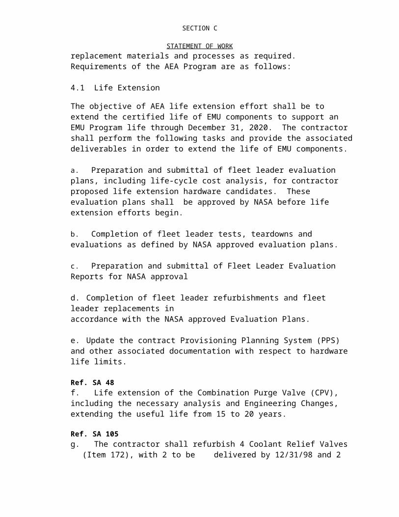
SECTION H
SPECIAL CONTRACT REQUIREMENTSto any other change(s). The parties recognize that several changes may be grouped together in a single contract modification for issuance or definitization; however, the dollar value of each individual change will be controlling in determining whether or not an equitable adjustment different from this agreement is in order.
H.6 CONTINUOUS IMPROVEMENT
(a) The Contractor shall implement and maintain vigorous continuous improvement (CI) activities for the full duration of this contract with the overarching goals of improving productivity, achieving cost savings, and achieving other economies and efficiencies across the full spectrum of its performance of this contract and the performance of its subcontractors (at all tiers) whose subcontracts exceed a total of $10 million over the base period of this contract. The Contractor’s plan is incorporated herein as Section J-2 Program Management Plan.
(b) As part of its CI activities, the Contractor shall maintain data regarding its achievement of each of the Performance Requirements specified Section J-3 Contract Metrics to this contract and its performance in relationship to those Performance Requirements. Although the Contractor may use any system and format to maintain this data, the data must be easily and continuously accessible to the Government pursuant to the Access to Contractor Data clause and be complete enough to be meaningful.
(c) The parties recognize that the Government may need to change policies or requirements in this contract in order to enable the Contractor to achieve specific efficiencies under this contract. The Contractor, therefore, is encouraged to request these changes when they may result in additional improvements or cost savings. The Government will, in good faith, consider accepting these changes. In the event that the Government cannot accept a suggestion, it will provide rationale to the Contractor as to why the suggestion was unacceptable. When possible, the Government shall propose modifications to a suggestion in order to make it acceptable. The Government’s rejection of a suggestion submitted pursuant to this clause shall not provide the basis for a dispute under the Disputes clause, any equitable adjustment in accordance with the Changes clause, or an adjustment of fee that might otherwise have been earned.
(d) This clause is not an advance agreement on the part of NASA to accept any changes made pursuant to this clause. Moreover, the Contractor shall not request any changes that degrade either the safety of the program or the ability to meet the flight manifest. Additionally, the Government cannot accept any change which modifies or otherwise is contrary to a statute, an Executive Order, or a regulation issued by another Government agency.
(e) The Changes clause shall not apply to any suggestion accepted pursuant to this clause. Instead, this clause shall be cited as authority for any changes that are required to accept the Contractor’s suggestion. Additionally, for a period of three years

SECTION H
SPECIAL CONTRACT REQUIREMENTSafter implementation of a specific cost savings idea, an equitable adjustment shall not be required for changes resulting from this clause.
(f) The Contractor understands and agrees that, this clause notwithstanding, it is responsible for performance of all contract requirements.
H.7 POTENTIALLY HAZARDOUS ITEMS
The Contractor shall furnish complete design information and drawings showing all details of construction, including materials, for the following items designated as potentially hazardous: Pressure Vessels
The Contractor shall promptly notify the Contracting Officer, in writing, of any other items which he may, during the term of this contract, believe to be potentially hazardous.
H.8 MANAGEMENT AND PROTECTION OF INFORMATION
(a) It is anticipated that the Contractor will have access to, be furnished, or use the following types of recorded information:
(1) Information of third parties with limited rights or restricted rights notices submitted to NASA or directly to the Contractor.(2) Information of third parties which NASA has agreed to handle under protective arrangements.
(3) Information of which NASA intends to control the use and dissemination.
(b) In order to provide appropriate management for protecting such information, the Contractor agrees with respect to such information to (1) use and disclose such information only to the extent necessary to perform the work required under this contract, with particular emphasis on restricting the information to those “need to know” employees, and (2) to establish the necessary procedures to preclude disclosure of such information outside the Contractor employees assigned work area, except in accordance with the written instructions of the Contracting Officer.
H.9 SPECIAL AGREEMENT REGARDING INDEPENDENT RESEARCH AND DEVELOPMENT (IR&D)
The Contractor `hereby agrees to allocate and expend Independent Research and Development ((R&D) funds amounting to at least $500,000 per year for the base period and all option periods. The parties agree that none of the funds shall be expended toward the performance of tasks set forth in this contract; rather, the funds shall be directed toward appropriate research and development for EVA related activities. Finally, the parties agree that NASA will be granted limited rights to the data and related information developed with these funds and that such information will be reported to NASA personnel from time to time in such format and manner as the Contracting Officer may request.

SECTION H
SPECIAL CONTRACT REQUIREMENTS
H.10 SAFETY AND HEALTH PLAN
(a) The standards, plans, and reporting procedures contemplated by Clause 18-52.223-70 entitled "Safety and Health," are described in the Section J-6 Safety and Health Plan.
(b) The Contractor shall provide for safety inspection and acceptance of work imposed by the SOW. Safety inspection and corrective action reports shall be made available to the Contracting Officer upon request.
(c) The Contractor shall immediately report to the cognizant center Director of Safety and Mission Assurance and the cognizant Contracting Officer (by telephone if possible) accidents and incidents which result in serious personal injuries or death; and incidents which result in substantial damage to resources, equipment or facilities used or occupied by the Contractor. Prepare and submit a NASA Mishap Report per local center requirements.
H.11 GOVERNMENT INSIGHT
(a) Definitions. For the purpose of this contract, the following definitions apply:
“Insight,” as used in this clause, means technical visibility into the Program, maintained through audit, surveillance, assessment of trends and metrics, software independent verification and validation, the flight readiness review process, and review or independent assessment of out-of-family anomalies occurring in any phase of the program.
“Surveillance,” as used in this clause means continual monitoring and verification of the status of manufacturing, testing, and processing of Shuttle hardware, software and operations preparations to ensure that requirements are being fulfilled. Items to be monitored and verified are selected—this is not an all inclusive activity.
H.12 ENGINEERING CHANGE PROPOSALS
(a) Definitions.
"ECP" means an Engineering Change Proposal (ECP) which is a proposed engineering change and the documentation by which the change is described, justified, and submitted to the procuring activity for approval or disapproval. "NSTS 07700" means the NASA publication entitled, Space Shuttle Flight and Ground Specifications.
(b) Either party to the contract may originate ECPs. The originator shall forward proposed ECPs to the Contracting Officer. Unless otherwise required by the Contracting Officer, the ECP formats, forms and controls specified in NSTS 07700,

SECTION H
SPECIAL CONTRACT REQUIREMENTSVolume IV, Book 1 shall be used for Shuttle operations and in ISS 41170 for Space Station operations. Implementation of an approved ECP may occur by either a supplemental agreement or, if appropriate, as a written change order to the contract.
(c) Any ECP submitted to the Contracting Officer over $1M, shall include a "not-to-exceed" estimated cost increase or decrease adjustment amount, if any, and the required time of delivery adjustment, if any, acceptable to the originator of the ECP. If the change is originated within the Government, the Contracting Officer shall obtain a written agreement with the contractor regarding the "not-to-exceed" estimated cost and delivery adjustments, if any, prior to issuing an order for implementation of the change. An ECP accepted in accordance with the Changes clause of this contract shall not be considered an authorization to the Contractor to exceed the estimated cost in the contract Schedule, unless the estimated cost is increased by the change order or other contract modification.
(d) The contractor shall, in accordance with FAR 15.804-6, provide a completed Standard Form 1411, Contract Pricing Proposal Cover Sheet (Cost or Pricing Data Required), with appropriate attachments. At the time of agreement on the estimated cost amount, the contractor may be required to execute and submit to the Contracting Officer a Certificate of Current Cost or Pricing Data (FAR 15.804-2 and 15.804-4).
H.13 SPACE FLIGHT MOTIVATION AWARENESS PROGRAM
The Contractor shall maintain a product and performance-oriented motivation (awareness) program in accordance with Safety NHB 1700.1 (VI-B). The Program objective shall be the prevention of human error by instilling in individuals performing on the contract and on critical subcontracts an awareness of individual responsibility for ISS, Shuttle, and any other ancillary mission/payloads related to human space flight. As a minimum, goals should be to assure mission success, flight crew safety, and recognition of exemplary performance necessary to achieve success. The program shall include as a minimum:
(a) Participation in NASA-Industry Space Flight Awareness Program.
(b) Goal setting and measurement to provide documented practical goals and performance standards for the reduction and elimination of human errors at organizational and individual employee levels. (c) Error Cause Identification and Removal System for detecting human errors, relating them to an identifiable cause, and action to remove the cause.
(d) Methods to obtain and distribute motivational information and materials to concerned Contractor personnel, subcontractors, and vendors supplying critical flight and ground support hardware and software.
(e) Motivational (awareness) indoctrination for Contractor supervisory personnel and indoctrination of the work force in workmanship needs.

SECTION H
SPECIAL CONTRACT REQUIREMENTS
(f) Recognition of personnel who demonstrate their awareness through exceptional craftsmanship, error free workmanship, and attention to careful performance in their job responsibility. The Contractor shall flow down the provisions of this clause to all critical subcontractors.
H-14 HUMAN SPACE FLIGHT ITEM NASA 18.52.246-73 (MARCH 1997)
The Contractor shall include the following statement in all subcontracts and purchase orders placed by it in support of this contract, without exception as to amount or subcontract level:
"FOR USE IN HUMAN SPACE FLIGHT; MATERIALS, MANUFACTURING, AND WORKMANSHIP OF HIGHEST QUALITY STANDARDS ARE ESSENTIAL TO ASTRONAUT SAFETY.
IF YOU ARE ABLE TO SUPPLY THE DESIRED ITEM WITH A HIGHER QUALITY THAN THAT OF THE ITEMS SPECIFIED OR PROPOSED, YOU ARE REQUESTED TO BRING THIS FACT TO THE IMMEDIATE ATTENTION OF THE PURCHASER."
H.15 REQUIREMENT FOR COST TRACKING
Costs for the Space Shuttle and ISS shall be tracked and reported separately in order to comply with requirements that accurate and timely reporting of ISS costs to the Congress can be accomplished by NASA. These costs, to be reported in accordance with the requirements of 1852.242-73, NASA Contractor Financial Management Reporting. Cost tracking data shall be reported on the Earned Value Report (DRD No.3)
H.16 KEY PERSONNEL (1852.235-71) (MAR 1989)
The personnel and/or facilities listed below (or specified in the contract Schedule) are considered essential to the work being performed under this contract. Before removing, replacing, or diverting any of the listed or specified personnel or facilities, the Contractor shall (1) notify the Contracting Officer reasonably in advance and (2) submit justification (including proposed substitutions) in sufficient detail to permit evaluation of the impact on this contract.
(a) The Contractor shall make no diversion without the Contracting Officer’s written consent: provided that the Contracting Officer may ratify in writing the proposed change, and that ratification shall constitute the Contracting Officer’s consent required by this clause.
(b) The list of personnel and/or facilities (shown below or as specified in the contract Schedule) may, with the consent of the contracting parties, be amended from time to time during the course of the contract to add or delete personnel and/or facilities.

SECTION H
SPECIAL CONTRACT REQUIREMENTS
FOIA b4 exemption – Key Personnel
H.16 REPRESENTATIONS, CERTIFICATIONS, AND OTHER STATEMENTS OF OFFERORS (JSC 52.209-90) (SEPTEMBER 1988)
This contract incorporates Section K, Representations, Certifications, and Other Statements of Offerors, as set forth in the contractor's proposal No. HSPC 97T21 dated June 23, 1997, by reference, with the same force and effect as if it were given in full text.
THIS CLAUSE WAS INCORPORATED INTO SAs 267 & 269 ONLY2. Employee Stock Ownership Plan ("ESOP") Costs Clause:
On 10 February 2000, the U.S. Government’s Corporate Administrative Contracting Officer issued an initial finding that United Technologies Corporation does not comply with Cost Accounting Standard 415.50(e)(1) regarding the measurement of costs on the Corporation’s ESOP. The Corporation disagrees with this finding. The estimated cost of this contract is subject to reduction in the event the Government’s position on the alleged CAS 415 noncompliance is finally upheld by a Board of Contract Appeals or court of competent jurisdiction, or by mutual agreement. The parties to this contract agree that the estimated cost of this contract contains disputed ESOP costs. The estimated cost will be adjusted in a manner mutually agreeable to the parties once total allowable ESOP costs are finally determined. The amount of the adjustment will include the excess ESOP costs paid under this agreement, and applicable interest, in accordance with FAR 52.230-2 (a)(5). If this contract is over ceiling or target cost, the parties agree to negotiate an equitable reduction in the adjustment otherwise required to account for costs in excess of the ceiling / target.
SECTION I
CONTRACT CLAUSEI.1 Listing Of Clauses Incorporated By Reference
The following clauses are incorporated by reference in accordance with Federal Acquisition Regulation (FAR) 52.252-2 CLAUSES INCORPORATED BY REFERENCE (JUN 1988):
I. FEDERAL ACQUISITION REGULATION (48 CFR CHAPTER 1)
52.202-1 DEFINITIONS (OCT 1995)52.203-3 GRATUITIES (APR 1984)52.203-5 COVENANT AGAINST CONTINGENT FEES (APR 1984)52.203-6 RESTRICTIONS ON SUBCONTRACTOR SALES TO THE
GOVERNMENT (JUL 1995)52.203-7 ANTI-KICKBACK PROCEDURES (JUL 1995)52.203-8 CANCELLATION, RESCISSION, AND RECOVERY OF FUNDS FOR
ILLEGAL OR IMPROPER ACTIVITY (JAN 1997) 52.203-10 PRICE OR FEE ADJUSTMENT FOR ILLEGAL OR IMPROPER
ACTIVITY (JAN 1997)52.203-12 LIMITATION ON PAYMENTS TO INFLUENCE CERTAIN FEDERAL
TRANSACTIONS (JUN 1997)52.204-2 SECURITY REQUIREMENTS (AUG 1996)52.204-4 PRINTING/COPYING DOUBLE SIDED ON RECYCLED PAPER
(JUN 1996)52.209-6 PROTECTING THE GOVERNMENT'S INTEREST WHEN
SUBCONTRACTING WITH CONTRACTORS DEBARRED, SUSPENDED, OR PROPOSED FOR DEBARMENT (JUL 1995)
52.211-5 NEW MATERIAL (MAY 1995)52.211-7 OTHER THAN NEW MATERIAL, RESIDUAL INVENTORY, AND
FORMER GOVERNMENT SURPLUS PROPERTY (MAY 1995)52.211-15 DEFENSE PRIORITY AND ALLOCATION REQUIREMENTS
(SEP 1990)52.215-2 AUDIT AND RECORDS--NEGOTIATION (AUG 1996)52.215-22 PRICE REDUCTION FOR DEFECTIVE COST OR PRICING DATA
(OCT 1995)52.215-24 SUBCONTRACTOR COST OR PRICING DATA (OCT 1995)52.215-26 INTEGRITY OF UNIT PRICES (JAN 1997) --ALTERNATE I (JAN
1997)52.215-27 TERMINATION OF DEFINED BENEFIT PENSION PLANS (MAR
1996)52.215-33 ORDER OF PRECEDENCE (JAN 1986)52.215-39 REVERSION OR ADJUSTMENT OF PLANS FOR
POSTRETIREMENT BENEFITS OTHER THAN PENSIONS (PRB) (MAR 1996)
52.215-40 NOTIFICATION OF OWNERSHIP CHANGES (FEB 1995)52.215-42 REQUIREMENTS FOR COST OR PRICING DATA OR
INFORMATION

SECTION I
CONTRACT CLAUSE OTHER THAN COST OR PRICING DATA - MODIFICATIONS
(JAN 1997)52.216-7 ALLOWABLE COST AND PAYMENT (MAR 2000) REF. SA 27252.216-10 INCENTIVE FEE (MAR 1997)52.216-18 ORDERING (OCT. 1995) REF. SA 8752.216-19 ORDER LIMITATIONS (OCT. 1995) REF. SA 8752.216-22 INDEFINITE QUANTITY (OCT. 1995) REF. SA 8752.219-8 UTILIZATION OF SMALL, SMALL DISADVANTAGED AND
WOMEN-OWNED SMALL BUSINESS CONCERNS (JUN 1997)52.219-9 SMALL, SMALL DISADVANTAGED AND WOMEN-OWNED SMALL
BUSINESS SUBCONTRACTING PLAN (AUG 1996)52.219-16 LIQUIDATED DAMAGES--SUBCONTRACTING PLAN (OCT 1995)52.222-2 PAYMENT FOR OVERTIME PREMIUMS (JUL 1990) - ZERO 52.222-20 WALSH-HEALEY PUBLIC CONTRACTS ACT (DEC 1996)52.222-26 EQUAL OPPORTUNITY (APR 1984)52.222-28 EQUAL OPPORTUNITY PRE-AWARD CLEARANCE OF
SUBCONTRACTS (APR 1984)52.222-35 AFFIRMATIVE ACTION FOR SPECIAL DISABLED AND VIETNAM
ERA VETERANS (APR 1984)52.222-36 AFFIRMATIVE ACTION FOR HANDICAPPED WORKERS (APR
1984)52.222-37 EMPLOYMENT REPORTS ON SPECIAL DISABLED VETERANS
AND VETERANS OF THE VIETNAM ERA (JAN 1988)52.223-2 CLEAN AIR AND WATER (APR 1984)52.223-3 HAZARDOUS MATERIAL IDENTIFICATION AND MATERIAL
SAFETY DATA (JAN 1997) ALT 1 (JUL 1995)52.223-3 HAZARDOUS MATERIAL IDENTIFICATION AND MATERIAL
SAFETY DATA (JAN 1997)52.223-6 DRUG FREE WORK PLACE (JAN 1997)52.223-14 TOXIC CHEMICAL RELEASE REPORTING (OCT 1996)52.225-9 BUY AMERICAN ACT-TRADE AGREEMENTS-BALANCE OF
PAYMENTS PROGRAM (JAN 1996)52.225-10 DUTY-FREE ENTRY (APR 1984)52.225-11 RESTRICTIONS ON CERTAIN FOREIGN PURCHASES (OCT
1996)52.227-1 AUTHORIZATION AND CONSENT (JUL 1995)52.227-2 NOTICE AND ASSISTANCE REGARDING PATENT AND COPY-
RIGHT INFRINGEMENT (AUG 1996)52.227-14 RIGHTS IN DATA - GENERAL (JUN 1987) (ALT II) (JUN 1987)52.227-16 ADDITIONAL DATA REQUIREMENTS (JUN 1987)52.228-7 INSURANCE--LIABILITY TO THIRD PERSONS (MAR 1996)52.230-2 COST ACCOUNTING STANDARDS (APR 1996)52.230-6 ADMINISTRATION OF COST ACCOUNTING STANDARDS (APR
1996)52.232-9 LIMITATION ON WITHHOLDING OF PAYMENTS (APR 1984)52.232-17 INTEREST (JUNE 1996)

SECTION I
CONTRACT CLAUSE52.232-22 LIMITATION OF FUNDS (APR 1984) AS MODIFIED BY NASA FAR
SUPPLEMENT 18-32.705-252.232-23 ASSIGNMENT OF CLAIMS (JAN 1986)52.232-25 PROMPT PAYMENT (JUN 1997) (B)(2), SECOND SENTENCE,
SHALL HAVE A 30 DAY PERIOD FOR ANY CONTRACT FINANCING PAYMENTS
52.232-33 MANDATORY INFORMATION FOR ELECTRONIC FUNDS TRANSFER PAYMENT (AUG 1996)
52.233-1 DISPUTES (OCT 1995) - ALTERNATE I (DEC 1991)52.233-3 PROTEST AFTER AWARD (AUG 1996) - ALTERNATE I (JUN 1985)52.237-2 PROTECTION OF GOVERNMENT BUILDINGS, EQUIPMENT, AND
VEGETATION (APR 1984)52.242-1 NOTICE OF INTENT TO DISALLOW COSTS (APR 1984)52.242-3 PENALTIES FOR UNALLOWABLE COSTS (OCT 1995)52.242-4 CERTIFICATE OF FINAL INDIRECT COSTS (JAN 1997)52.242-13 BANKRUPTCY (JUL 1995)52.243-2 CHANGES--COST-REIMBURSEMENT (AUG 1987)52.243-7 NOTIFICATION OF CHANGES (APR 1984)52.244-2 SUBCONTRACTS (COST-REIMBURSEMENT AND LETTER
CONTRACTS) (FEB 1997)--ALTERNATE I (AUG 1996) {PARAGRAPH (E) IS "NONE"}
52.244-5 COMPETITION IN SUBCONTRACTING (DEC 1996)52.244-6 SUBCONTRACTS FOR COMMERCIAL ITEMS AND COMMERCIAL
COMPONENTS (OCT 1995)52.245-5 GOVERNMENT PROPERTY (COST-REIMBURSEMENT, TIME-
AND-MATERIALS, OR LABOR-HOUR CONTRACTS) (JAN 1986)52.245-18 SPECIAL TEST EQUIPMENT (FEB 1993)52.245-19 GOVERNMENT PROPERTY FURNISHED "AS IS" (APR 1984)52.246-24 LIMITATION OF LIABILITY--HIGH VALUE ITEMS (FEB 1997)52.248-1 VALUE ENGINEERING (MAR 1989)52.249-6 TERMINATION (COST-REIMBURSEMENT) (SEP 1996)52.249-14 EXCUSABLE DELAYS (APR 1984)52.251-1 GOVERNMENT SUPPLY SOURCES (APR 1984)52.253-1 COMPUTER GENERATED FORMS (52.253-1) (JAN 1991)
II. NASA FEDERAL ACQUISITION REGULATION (48 CFR CHAPTER 18)
18-52.215-84 OMBUDSMAN (OCT 1996) THE JSC OMBUDSMAN IS CHARLES J. PRECOURT, COL USAFTHOMAS AT 281-483-3699. THE NASA OMBUDSMAN IS S. LUEDTKE AT 202-358-2090.
18-52.219-74 USE OF RURAL AREA SMALL BUSINESSES (SEP 1990)18-52.219-75 SMALL BUSINESS AND SMALL DISADVANTAGED BUSINESS
SUBCONTRACTING REPORTING (JUN 1997)18-52.219-76 NASA 8 PERCENT GOAL (JUL 1997)18-52.227-14 RIGHTS IN DATA - GENERAL 1852.228-75 MINIMUM INSURANCE COVERAGE (OCT 1988)
SECTION I
CONTRACT CLAUSE18-52.235-70 CENTER FOR AEROSPACE INFORMATION SERVICES (NOV
1992)18-52.237-70 EMERGENCY EVACUATION PROCEDURES (DEC 1988)18-52.243-70 ENGINEERING CHANGE PROPOSALS ALTERNATE I & II (MAR
1997) 18-52.244-70 GEOGRAPHIC PARTICIPATION AEROSPACE PROGRAM (APR
1985)
III. CLAUSES INCORPORATED BY REFERENCE WHICH ARE APPLICABLE TO THE CARRY-OVER EFFORT FROM NAS 9-17873
A. COST-PLUS-INCENTIVE-FEE; COST-PLUS-FIXED-FEE
52.202-1 DEFINITIONS (SEP 1991) (ALTERNATE I) (APR 1984)52.209-6 PROTECTING THE GOVERNMENT'S INTEREST WHEN SUBCONTRACTING
WITH CONTRACTORS DEBARRED, SUSPENDED, OR PROPOSED FOR DEBARMENT (NOV 1992)
52.212-8 DEFENSE PRIORITY ANDALLOCATION REQUIREMENTS (SEP 1990)
52.215-1 EXAMINATION OF RECORDSBY COMPTROLLER GENERAL (FEB 1993)
52.215-2 AUDIT--NEGOTIATION (FEB 1993)52.215-21 CHANGES OR ADDITIONS TO MAKE BUY PROGRAM (ALTERNATE II)
(APR 1994)52.215-23 PRICE REDUCTION FOR DEFECTIVE COST OR PRICING DATA -
MODIFICATIONS) (DEC 1994)52.215-24 SUBCONTRACTOR COST OR PRICING DATA (DEC 1994)52.215-25 SUBCONTRACTOR COST OR PRICING DATA - MODIFICATIONS (DEC 1994)52.223-3 HAZARDOUS MATERIAL
IDENTIFICATION AND MATERIAL SAFETY DATA (NOV 1991)52.225-3 BUY AMERICAN ACT--SUPPLIES (JAN 1994)52.225-11 RESTRICTIONS ON CERTAIN FOREIGN PURCHASES (MAY 1992)52.230-2 COST ACCOUNTING STANDARDS (AUG 1992)52.230-5 ADMINISTRATION OF COST ACCOUNTING STANDARDS (FEB 1995)52.232-25 PROMPT PAYMENT (MAR 1994)52.233-1 DISPUTES (MAR 1994)52.245-18 SPECIAL TEST EQUIPMENT (FEB 1993)
II. NASA FAR SUPPLEMENT (48 CFR CHAPTER 18)
18-52.223-70 SAFETY AND HEALTH (SEP 1993)18-52.223-73 SAFETY & HEALTH PLAN (DEC 1988)18-52.228-72 CROSS WAIVER OF LIABILITY COVERING SHUTTLE OPERATIONS
(SEP 1993)18-52.215-78 MAKE OR BUY PROGRAM REQUIREMENTS (DEC 1988)

SECTION I
CONTRACT CLAUSE18-52.228-76 CROSS WAIVER OF LIABILITY FOR SPACE STATION ACTIVITIES
INFORMATION IN THE AEROSPACE PROGRAM (DEC 1994)18-52.243-70 ENGINEERING CHANGE PROPOSALS (SEP 1993) ALTERNATE I (SEP 1990) $400,00018-52.245-70 ACQUISITION OF CENTRALLY REPORTABLE EQUIPMENT(MAR 1989)18-52.245-73 FINANCIAL REPORTING OF NASA PROPERTY IN THE CUSTODY
OF CONTRACTORS (SEP 1996)
B. FIXED PRICE CLAUSES:
52.208-1 REQUIRED SOURCES FOR JEWEL BEARINGS AND RELATEDITEMS (APR 1984)
52.229-4 FEDERAL, STATE, AND LOCAL TAXES (NONCOMPETITIVE CONTRACT) (JAN 1991)
52.232-1 PAYMENTS (APR 1984)52.232-8 DISCOUNTS FOR PROMPT PAYMENT (APR 1989)52.232-11 EXTRAS (APR 1984)52.232-16 PROGRESS PAYMENTS (JUL 1991)52.242-15 STOP-WORK ORDER (AUG 1989)52.242-17 GOVERNMENT DELAY OF WORK (APR 1984)52.243-1 CHANGES—FIXED-PRICE (AUG 1987)52.245-2 GOVERNMENT PROPERTY (FIXED-PRICE CONTRACTS) (DEC 1989)52.246-16 RESPONSIBILITY FOR SUPPLIES (APR 1984) 52.249-2 TERMINATION FOR THE CONVENIENCE OF THE GOVERNMENT
(FIXED-PRICE) (SEP 1996) 52.249-8 DEFAULT (FIXED-PRICE SUPPLY AND SERVICE) (APR 1984)
B. NASA/FAR SUPPLEMENT (48 CFR CHAPTER 18) CLAUSES
18-52.212-70 NOTICE OF DELAY (DEC 1988)
(End of By Reference Section)
I.2 APPROVAL OF CONTRACT (52.204-1)
This contract is subject to written approval of the JSC Procurement Officer and shall not be binding until so approved.
(End of Clause)
I.3 LIMITATION ON WITHHOLDING OF PAYMENTS (52.232-9) (APR 1984)

SECTION I
CONTRACT CLAUSEIf more than one clause or Schedule term of this contract authorizes the temporary withholding of amounts otherwise payable to the Contractor for supplies delivered or services performed, the total of the amounts withheld at any one time shall not exceed the greatest amount that may be withheld under any one clause or Schedule term at that time; provided, that this limitation shall not apply to--
(a) Withholdings pursuant to any clause relating to wages or hours of employees;
(b) Withholdings not specifically provided for by this contract;
(c) The recovery of overpayments; and
(d) Any other withholding for which the Contracting Officer determines that this limitation is inappropriate.
(End of Clause)
i. 4 CLAUSES INCORPORATED BY REFERENCE (52.252-2) (JUN 1988)
This contract incorporates one or more clauses by reference, with the same force and effect as if they were given in full text. Upon request, the Contracting Officer will make their full text available.
(End of Clause)
I.5 ALTERATIONS IN CONTRACT (52.252-4) (APR 1984)
Portions of this contract are altered as follows:
Clause 52.243-2, Changes - Cost-Reimbursement, is modified by deleting the 30-day reference and inserting a reference to 60 days in lieu thereof.
(End of Clause)
SECTION J
LIST OF ATTACHMENTS
Attachment Title
J-1 Data Requirements List (DRL) & Data Requirements Documents
J-2 Program Management Plan
J-3 Contract Metrics
J-4 Performance Evaluation (Fee) Plan
J-5 Program Provisioning
J-6 Hardware Quantities and Delivery Schedules
J-7 Hardware Refurbishment Quantitiesand Schedules
J-8 Hardware Provisioning List
J-9 Safety and Health Plan
J-10 Government Furnished Property
J-11 Installation Provided Services
J-12 Applicable Documents
J-13 NAS 9-17873 Carry-Over Effort
J-14 Quality Plan
J-15 Subcontracting Plan

SECTION J
LIST OF ATTACHMENTS

JSC DATA REQUIREMENTS LIST (DRL)a. Title of Contract, Project, SOW, etc. b. Contract/RFP No. c. DRL Date/Mod DateEMU Program Contract NAS 9-97150 3/21/97
1. Line item no.
2. DRD Title 3. Frequency 4. As-of-Date
5. 1st subm. date
6. Copies
a. type 1 b. numb1 Program Management Plan AR Print: 4
Electronic: 17. Data type: X (1) Written approval (2) Mandatory Submittal (3) Submitted upon request
8. Distribution (Continue on a blank sheet if needed) 9. RemarksTechnical Manager Resource AnalystContracting Officer Data Center
90 days after contract award and all revisions.
1. Line item no. 2. DRD Title 3. Frequency 4. As-of- 5. 1st subm. 6. a. type 1 b. 2 Work Breakdown Structure (WBS) and Dictionary AR Print:
Electronic: 17. Data type: X (1) Written approval (2) Mandatory Submittal (3) Submitted upon request
8. Distribution (Continue on a blank sheet if needed) 9. RemarksTechnical Manager Resource AnalystContracting Officer Data Center
90 days after contract award and all revisions.
1. Line item no. 2. DRD Title 3. Frequency 4. As-of- 5. 1st subm. 6. a. type 2 b. 3 Earned Value Financial Management Report Monthly Print: 5
Electronic: 17. Data type: (1) Written approval X (2) Mandatory Submittal (3) Submitted upon request
8. Distribution (Continue on a blank sheet if needed) 9. RemarksTechnical Manager Financial Management AnalystContracting Officer Data CenterResource Analyst
Baseline Plan - 30 days after contract award. Monthly reports due on the 20th calendar day of the month.
1. Line item no. 2. DRD Title 3. Frequency 4. As-of- 5. 1st subm. 6. a. type 1 b. 4 Metrics Plan AR Print: 4
Electronic: 17. Data type: (1) Written approval X (2) Mandatory Submittal (3) Submitted upon request
8. Distribution (Continue on a blank sheet if needed) 9. RemarksTechnical Manager Resource AnalystContracting Officer Data Center
JSC Form 2323 (Rev May 91) (MS Word Aug 95)

JSC DATA REQUIREMENTS LIST (DRL)a. Title of Contract, Project, SOW, etc. b. Contract/RFP No. c. DRL Date/Mod DateEMU Program Contract NAS 9-97150 3/21/97
1. Line item no.
2. DRD Title 3. Frequency 4. As-of-Date
5. 1st subm. date
6. Copies
a. type 1 b. number5 Configuration Management Plan AR Print: 4
Electronic: 17. Data type: X (1) Written approval (2) Mandatory Submittal (3) Submitted upon request
8. Distribution (Continue on a blank sheet if needed) 9. RemarksTechnical Manager Resource AnalystContracting Officer Data Center
90 days after contract award and all revisions.
1. Line item no. 2. DRD Title 3. Frequency 4. As-of- 5. 1st subm. 6. a. type 1 b. 6 Data Management Plan AR Print: 4
Electronic: 17. Data type: X (1) Written approval (2) Mandatory Submittal (3) Submitted upon request
8. Distribution (Continue on a blank sheet if needed) 9. RemarksTechnical Manager Resource AnalystContracting Officer Data Center
90 days after contract award and all revisions.
1. Line item no. 2. DRD Title 3. Frequency 4. As-of- 5. 1st subm. 6. a. type 1 b. 7 Government Property Management Plan AR Print: 4
Electronic: 17. Data type: X (1) Written approval (2) Mandatory Submittal (3) Submitted upon request
8. Distribution (Continue on a blank sheet if needed) 9. RemarksTechnical Manager Property AdministratorContracting Officer Data Center
90 days after contract award and all revisions.
1. Line item no. 2. DRD Title 3. Frequency 4. As-of- 5. 1st subm. 6. a. type 2 b. 8 Logistics Operations Reporting AR Print: 3
Electronic: 17. Data type: (1) Written approval X (2) Mandatory Submittal (3) Submitted upon request
8. Distribution (Continue on a blank sheet if needed) 9. RemarksContracting OfficerProperty AdministratorData Center
JSC Form 2323 (Rev May 91) (MS Word Aug 95)

JSC DATA REQUIREMENTS LIST (DRL)a. Title of Contract, Project, SOW, etc. b. Contract/RFP No. c. DRL Date/Mod DateEMU Program Contract NAS 9-97150 3/21/97
1. Line item no.
2. DRD Title 3. Frequency 4. As-of-Date
5. 1st subm. date
6. Copies
a. type 2
b. number9 New Technology Report Annually Print: 2
Electronic: 17. Data type: (1) Written approval X (2) Mandatory Submittal (3) Submitted upon request
8. Distribution (Continue on a blank sheet if needed) 9. RemarksContracting OfficerData Center
1. Line item no. 2. DRD Title 3. Frequency 4. As-of- 5. 1st subm. 6. a. type b. number10 EMU Processing and Constraints Document
(FEMU-R-001)AR Print: 6
Electronic: 17. Data type: (1) Written approval X (2) Mandatory Submittal (3) Submitted upon request
8. Distribution (Continue on a blank sheet if needed) 9. RemarksTechnical Manager S&MASSM ILCData Center BAO/FEPC Configuration
As amended.
1. Line item no. 2. DRD Title 3. Frequency 4. As-of- 5. 1st subm. 6. a. type b. number11 Interface Control Documents (ICD's) AR Print: 4
7. Data type: X (1) Written approval (2) Mandatory Submittal (3) Submitted upon request8. Distribution (Continue on a blank sheet if needed) 9. RemarksTechnical Manager BAO/FEPC ConfigurationSSM Data Center
1. Line item no. 2. DRD Title 3. Frequency 4. As-of- 5. 1st subm. 6. a. type b. number12 Mass Properties Report TY Print: 5
Electronic: 17. Data type: (1) Written approval X (2) Mandatory Submittal (3) Submitted upon request
8. Distribution (Continue on a blank sheet if needed) 9. RemarksTechnical Manager SR&QAContracting OfficerSSM
As part of Program Review package.
JSC Form 2323 (Rev May 91) (MS Word Aug 95)

JSC DATA REQUIREMENTS LIST (DRL)a. Title of Contract, Project, SOW, etc. b. Contract/RFP No. c. DRL Date/Mod DateEMU Program Contract NAS 9-97150 3/21/97
1. Line item no.
2. DRD Title 3. Frequency 4. As-of-Date
5. 1st subm. date
6. Copies
a. type 1 b. number13 Certification Plan / Procedures / Report AR Print: 5
Electronic: 1 7. Data type: X (1) Written approval (2) Mandatory Submittal (3) Submitted upon request
8. Distribution (Continue on a blank sheet if needed) 9. RemarksTechnical Manager SR&QASSM S&MAData Center
Cert plan and procedures requirements Section (a-i) 15 working days prior to PDR as part of DRD 42. Test parameter Section (J-P) 15 working days prior to CDR as part of DRD 34. Cert report submitted 30 days after test completion.
1. Line item no. 2. DRD Title 3. Frequency 4. As-of- 5. 1st subm. 6. a. type 2 b. 14 NASA EMU LSS and SSA Databook Annually Print: 145
7. Data type: (1) Written approval X (2) Mandatory Submittal (3) Submitted upon request8. Distribution (Continue on a blank sheet if needed) 9. RemarksCOTRSSM
120 days after contract definitization.
1. Line item no. 2. DRD Title 3. Frequency 4. As-of- 5. 1st subm. 6. a. type 1 b. 15 S&MA Certification Approval Request (SMACAR) AR Print: 4
Electronic: 17. Data type: X (1) Written approval (2) Mandatory Submittal (3) Submitted upon request
8. Distribution (Continue on a blank sheet if needed) 9. RemarksSSM SR&QAData Center S&MA
To be included as part of DRD 13 (Cert Report).
1. Line item no. 2. DRD Title 3. Frequency 4. As-of- 5. 1st subm. 6. a. type 1 b. RESERVED
7. Data type: X (1) Written approval (2) Mandatory Submittal (3) Submitted upon request8. Distribution (Continue on a blank sheet if needed) 9. RemarksTechnical Manager Resource AnalystContracting Officer Data Center
90 days after contract award and all revisions.
JSC Form 2323 (Rev May 91) (MS Word Aug 95)

JSC DATA REQUIREMENTS LIST (DRL)a. Title of Contract, Project, SOW, etc. b. Contract/RFP No. c. DRL Date/Mod DateEMU Program Contract NAS 9-97150 3/21/97
1. Line item no.
2. DRD Title 3. Frequency 4. As-of-Date
5. 1st subm. date
6. Copies
a. type 2
b. number17 Development and Design Test Procedures/Report AR Print: 5
Electronic: 17. Data type: (1) Written approval X (2) Mandatory Submittal (3) Submitted upon request
8. Distribution (Continue on a blank sheet if needed) 9. RemarksTechnical Manager SR&QASSM S&MAData Center
Test procedures due 30 days prior to test. Report due 30 days after test complete.
1. Line item no. 2. DRD Title 3. Frequency 4. As-of- 5. 1st subm. 6. a. type b. number18 Problem Reporting and Corrective Action (PRACA) AR Print: 5
Electronic: 17. Data type: X (1) Written approval (2) Mandatory Submittal (3) Submitted upon request
8. Distribution (Continue on a blank sheet if needed) 9. RemarksTechnical Manager SR&QASSM S&MAData Center
1. Line item no. 2. DRD Title 3. Frequency 4. As-of- 5. 1st subm. 6. a. type b. number19 Limited Life Items List (LLIL) AR Print: 6
Electronic: 17. Data type: X (1) Written approval (2) Mandatory Submittal (3) Submitted upon request
8. Distribution (Continue on a blank sheet if needed) 9. RemarksTechnical Manager SR&QASSM S&MAData Center BAO/FEPC Configuration
Submitted with DRD 34 15 working days prior to CDR and as required.
1. Line item no. 2. DRD Title 3. Frequency 4. As-of- 5. 1st subm. 6. a. type b. number20 Master Authorized Change Record (MACR) Report AR Print: 2
7. Data type: (1) Written approval X (2) Mandatory Submittal (3) Submitted upon request8. Distribution (Continue on a blank sheet if needed) 9. RemarksData CenterBAO/FEPC Configuration
JSC Form 2323 (Rev May 91) (MS Word Aug 95)
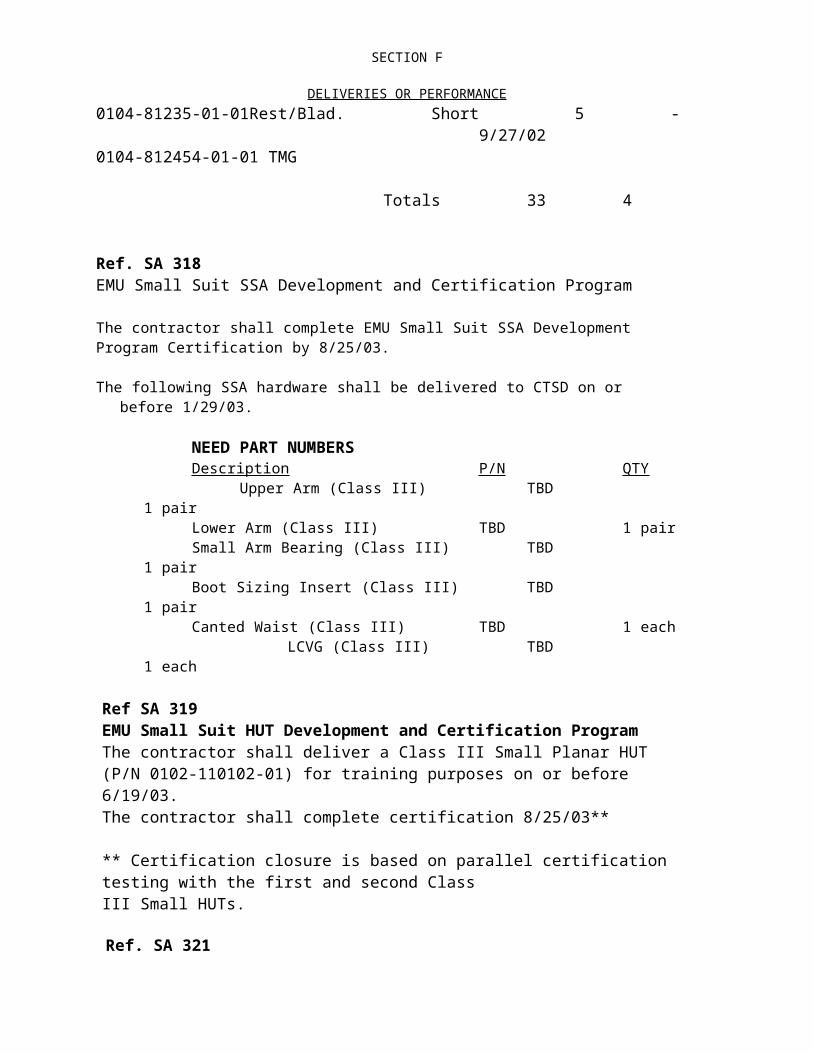
JSC DATA REQUIREMENTS LIST (DRL)a. Title of Contract, Project, SOW, etc. b. Contract/RFP No. c. DRL Date/Mod DateEMU Program Contract NAS 9-97150 3/21/97
1. Line item no.
2. DRD Title 3. Frequency 4. As-of-Date
5. 1st subm. date
6. Copies
a. type 1
b. number21 Predelivery Acceptance Test (PDA) AR Print: 4
Electronic: 17. Data type: X (1) Written approval (2) Mandatory Submittal (3) Submitted upon request
8. Distribution (Continue on a blank sheet if needed) 9. RemarksSSM SR&QAData Center S&MA
20 working days prior to start of test initiate procedures by TPS which will be approved at TRR.
1. Line item no. 2. DRD Title 3. Frequency 4. As-of- 5. 1st subm. 6. a. type b. number22 Hazardous Waste Quantity Report Annually Print: 1
Electronic: 17. Data type: (1) Written approval X (2) Mandatory Submittal (3) Submitted upon request
8. Distribution (Continue on a blank sheet if needed) 9. RemarksContracting Officer 90 days after contract definitization beginning of each calendar year.
1. Line item no. 2. DRD Title 3. Frequency 4. As-of- 5. 1st subm. 6. a. type b. number23 NASA/GIDEP Alert System Documentation AR Print: 5
Electronic: 17. Data type: (1) Written approval X (2) Mandatory Submittal (3) Submitted upon request
8. Distribution (Continue on a blank sheet if needed) 9. RemarksTechnical Manager S&MAContracting OfficerData CenterSSM
Alert report within 5 days of problem identification. Response to NASA alert within 21 days.
1. Line item no. 2. DRD Title 3. Frequency 4. As-of- 5. 1st subm. 6. a. type b. number24 Space Shuttle GFE Safety Analysis Report (SAR)
and Hazard Report (HR)Semi-Annually Print: 3
Electronic: 17. Data type: (1) Written approval X (2) Mandatory Submittal (3) Submitted upon request
8. Distribution (Continue on a blank sheet if needed) 9. RemarksSSM S&MAData CenterBAO/FEPC Configuration
15 working days prior to CDR along with DRD 34 with updates as required and 15 working days prior to PDR along with DRD 42.
JSC Form 2323 (Rev May 91) (MS Word Aug 95)
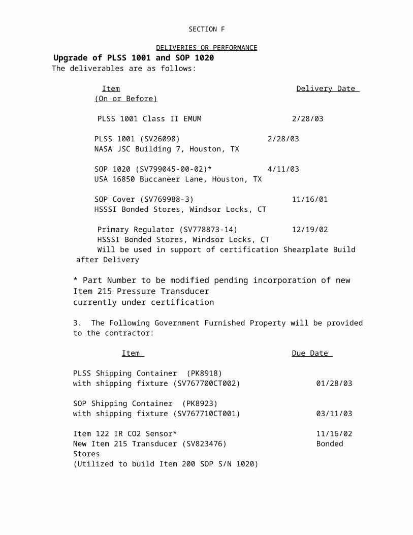
JSC DATA REQUIREMENTS LIST (DRL)a. Title of Contract, Project, SOW, etc. b. Contract/RFP No. c. DRL Date/Mod DateEMU Program Contract NAS 9-97150 3/21/97
1. Line item no.
2. DRD Title 3. Frequency 4. As-of-Date
5. 1st subm. date
6. Copies
a. type 2
b. number25 Accident/Incident Report and Safety Activities
ReportMonthly Print: 3
Electronic: 17. Data type: (1) Written approval X (2) Mandatory Submittal (3) Submitted upon request
8. Distribution (Continue on a blank sheet if needed) 9. RemarksTechnical ManagerContracting OfficerData Center
1. Line item no. 2. DRD Title 3. Frequency 4. As-of- 5. 1st subm. 6. a. type b. number26 Pressure Vessel Historical Data AR Print: 1
Electronic: 17. Data type: (1) Written approval X (2) Mandatory Submittal (3) Submitted upon request
8. Distribution (Continue on a blank sheet if needed) 9. RemarksData Center
1. Line item no. 2. DRD Title 3. Frequency 4. As-of- 5. 1st subm. 6. a. type b. number27 Pressure Vessel System Recertification AR Print: 3
Electronic: 17. Data type: (1) Written approval X (2) Mandatory Submittal (3) Submitted upon request
8. Distribution (Continue on a blank sheet if needed) 9. RemarksTechnical Manager S&MASSMData Center
1. Line item no. 2. DRD Title 3. Frequency 4. As-of- 5. 1st subm. 6. a. type b. number28 Space Station GFE Failure Modes and Effects
Analysis (FMEA) and Critical Items List (CIL)Semi-Annually Type 1, 2
Print: 47. Data type: X (1) Written approval X (2) Mandatory Submittal (3) Submitted upon request
8. Distribution (Continue on a blank sheet if needed) 9. RemarksTechnical Manager S&MA SSM Data Center
Note: FMEA is Type II document; CIL is Type I document; 15 working days prior to CDR along with DRD 34, with updates as required; and 15 working days prior to PDR along with DRD 42.
JSC Form 2323 (Rev May 91) (MS Word Aug 95)

JSC DATA REQUIREMENTS LIST (DRL)a. Title of Contract, Project, SOW, etc. b. Contract/RFP No. c. DRL Date/Mod DateEMU Program Contract NAS 9-97150 3/21/97
1. Line item no.
2. DRD Title 3. Frequency 4. As-of-Date
5. 1st subm. date
6. Copies
a. type 1
b. number29 Reliability & Maintainability Plan AR Print: 4
Electronic: 17. Data type: X (1) Written approval (2) Mandatory Submittal (3) Submitted upon request
8. Distribution (Continue on a blank sheet if needed) 9. RemarksTechnical Manager Data CenterSSMS&MA
90 days after contract definitization and all revisions.
1. Line item no. 2. DRD Title 3. Frequency 4. As-of- 5. 1st subm. 6. a. type b. number30 EEE Parts Data Requirements AR Print: 4
Electronic: 17. Data type: (1) Written approval X (2) Mandatory Submittal (3) Submitted upon request
8. Distribution (Continue on a blank sheet if needed) 9. RemarksSSM SR&QAData Center S&MA
Irregular EEE parts usage submit 21 days prior to parts procurement. EEE parts qualification test submit 20 working days prior to test. EEE parts specification submit 15 working days prior to PDR or 30 days after placement of order, whichever comes first. EEE part
1. Line item no. 2. DRD Title 3. Frequency 4. As-of- 5. 1st subm. 6. a. type b. number31 SR&QA Program Plan AR Print: 4
Electronic: 17. Data type: (1) Written approval X (2) Mandatory Submittal
(Ref. SA 285)(3) Submitted upon request
8. Distribution (Continue on a blank sheet if needed) 9. RemarksTechnical Manager Data CenterSSM SR&QA
90 days after contract definitization and all revisions.
1. Line item no. 2. DRD Title 3. Frequency 4. As-of- 5. 1st subm. 6. a. type b. number32 Acceptance Data Package (ADP) AR Print: 1
7. Data type: X (1) Written approval (2) Mandatory Submittal (3) Submitted upon request8. Distribution (Continue on a blank sheet if needed) 9. RemarksSee Section 9. One copy with each EMU hardware end item.
JSC Form 2323 (Rev May 91) (MS Word Aug 95)

JSC DATA REQUIREMENTS LIST (DRL)
a. Title of Contract, Project, SOW, etc. b. Contract/RFP No. c. DRL Date/Mod DateEMU Program Contract NAS 9-97150 3/21/97
1. Line item no.
2. DRD Title 3. Frequency 4. As-of-Date
5. 1st subm. date
6. Copies
a. type 2
b. number33 Authorized Change Record AR Print: 1
7. Data type: (1) Written approval X (2) Mandatory Submittal (3) Submitted upon request8. Distribution (Continue on a blank sheet if needed) 9. Remarks
Submitted as part of DRD 32.
1. Line item no. 2. DRD Title 3. Frequency 4. As-of- 5. 1st subm. 6. a. type b. number34 Critical Design Review Data Package AR Print: 20
Electronic: 1 (less drawings)7. Data type: (1) Written approval X (2) Mandatory Submittal (3) Submitted upon request
8. Distribution (Continue on a blank sheet if needed) 9. RemarksTechnical Manager SR&QASSM S&MAData Center
15 working days prior to CDR.
1. Line item no. 2. DRD Title 3. Frequency 4. As-of- 5. 1st subm. 6. a. type b. number35 Microfilming of Engineering and Associated Lists
DocumentAR Print: 2
7. Data type: (1) Written approval X (2) Mandatory Submittal (3) Submitted upon request8. Distribution (Continue on a blank sheet if needed) 9. RemarksData CenterBAO/FEPC Configuration
Released drawings and associated lists.
1. Line item no. 2. DRD Title 3. Frequency 4. As-of- 5. 1st subm. 6. a. type b. number36 Engineering Change Order AR Print: 2
7. Data type: (1) Written approval X (2) Mandatory Submittal (3) Submitted upon request8. Distribution (Continue on a blank sheet if needed) 9. RemarksData CenterBAO/FEPC Configuration
JSC Form 2323 (Rev May 91) (MS Word Aug 95)

JSC DATA REQUIREMENTS LIST (DRL)
a. Title of Contract, Project, SOW, etc. b. Contract/RFP No. c. DRL Date/Mod DateEMU Program Contract NAS 9-97150 3/21/97
1. Line item no.
2. DRD Title 3. Frequency 4. As-of-Date
5. 1st subm. date
6. Copies
a. type 2
b. number37 Engineering Drawings and Associated Lists Print: 2
7. Data type: (1) Written approval X (2) Mandatory Submittal (3) Submitted upon request8. Distribution (Continue on a blank sheet if needed) 9. RemarksData CenterBAO/FEPC Configuration
1. Line item no. 2. DRD Title 3. Frequency 4. As-of- 5. 1st subm. 6. a. type b. number38 Fracture Control Plan AR Print: 6
Electronic: 17. Data type: X (1) Written approval (2) Mandatory Submittal (3) Submitted upon request
8. Distribution (Continue on a blank sheet if needed) 9. RemarksTechnical Manager SR&QASSM Data CenterBAO/FEPC Configuration S&MA
90 days after contract definitization.
1. Line item no. 2. DRD Title 3. Frequency 4. As-of- 5. 1st subm. 6. a. type b. number39 Development Test(s) Plan AR Print: 5
Electronic: 17. Data type: X (1) Written approval (2) Mandatory Submittal (3) Submitted upon request
8. Distribution (Continue on a blank sheet if needed) 9. RemarksTechnical Manager SR&QASSMData Center
Plan Identified in 2 sections: Section 1 due with PDR package 15 working days prior to PDR along with DRD 42; Section 2 due 20 days prior to test.
1. Line item no. 2. DRD Title 3. Frequency 4. As-of- 5. 1st subm. 6. a. type b. number40 Material Control and Verification Program Plan
(MATCO)Print: 3Electronic: 1
7. Data type: X (1) Written approval (2) Mandatory Submittal (3) Submitted upon request8. Distribution (Continue on a blank sheet if needed) 9. RemarksTechnical Manager MaterialsData Center
90 days after contract definitization and all revisions.
JSC Form 2323 (Rev May 91) (MS Word Aug 95)

JSC DATA REQUIREMENTS LIST (DRL)
a. Title of Contract, Project, SOW, etc. b. Contract/RFP No. c. DRL Date/Mod DateEMU Program Contract NAS 9-97150 3/21/97
1. Line item no.
2. DRD Title 3. Frequency 4. As-of-Date
5. 1st subm. date
6. Copies
a. type 2
b. number41 Preliminary Design Review (PDR) and Critical
Design Review (CDR) ReportAR Print: 20
Electronic: 1 (less drawings)7. Data type: (1) Written approval X (2) Mandatory Submittal (3) Submitted upon request
8. Distribution (Continue on a blank sheet if needed) 9. RemarksTechnical Manager SR&QASSM S&MAData Center
Delivery 10 after RID or action items review.
1. Line item no. 2. DRD Title 3. Frequency 4. As-of- 5. 1st subm. 6. a. type b. number42 Preliminary Design Review Data Package AR Print: 20
Electronic: 1 (less drawings)7. Data type: (1) Written approval X (2) Mandatory Submittal (3) Submitted upon request
8. Distribution (Continue on a blank sheet if needed) 9. RemarksTechnical Manager SR&QASSM S&MAData Center
15 working days prior to PDR.
1. Line item no. 2. DRD Title 3. Frequency 4. As-of- 5. 1st subm. 6. a. type b. number43 Specification/Assembly Drawing (S/AD) AR Print: 5
7. Data type: (1) Written approval X (2) Mandatory Submittal (3) Submitted upon request8. Distribution (Continue on a blank sheet if needed) 9. RemarksSSMData Center BAO/FEPC ConfigurationSR&QA
Submit with PDR package 15 working prior to PDR along with DRD 42; submit with CDR package (DRD 34) 15 working days prior to CDR.
1. Line item no. 2. DRD Title 3. Frequency 4. As-of- 5. 1st subm. 6. a. type b. number44 Structural Stress Analysis Report AR Print: 3
Electronic: 17. Data type: X (1) Written approval (2) Mandatory Submittal (3) Submitted upon request
8. Distribution (Continue on a blank sheet if needed) 9. RemarksSSMData CenterS&MA
To be accomplished for all new or structural redesigned hardware.
JSC Form 2323 (Rev May 91) (MS Word Aug 95)

JSC DATA REQUIREMENTS LIST (DRL)
a. Title of Contract, Project, SOW, etc. b. Contract/RFP No. c. DRL Date/Mod DateEMU Program Contract NAS 9-97150 3/21/997
1. Line item no.
2. DRD Title 3. Frequency 4. As-of-Date
5. 1st subm. date
6. Copies
a. type 1
b. number45 System Design and Performance Requirements
Document (SN07800)AR Print: 5
Electronic: 17. Data type: X (1) Written approval (2) Mandatory Submittal (3) Submitted upon request
8. Distribution (Continue on a blank sheet if needed) 9. RemarksTechnical Manager SR&QASSM S&MAData Center
30 days after contract definitization and all revisions.
1. Line item no. 2. DRD Title 3. Frequency 4. As-of- 5. 1st subm. 6. a. type b. number46 Cleaning, Preservation, Packaging, Handling,
Storage, and Shipping ProcedureAR Print: 5
Electronic: 17. Data type: X (1) Written approval (2) Mandatory Submittal (3) Submitted upon request
8. Distribution (Continue on a blank sheet if needed) 9. RemarksTechnical Manager Data CenterSR&QA BAO/FEPC ConfigurationS&MA
15 working days prior to CDR with DRD 34.
1. Line item no. 2. DRD Title 3. Frequency 4. As-of- 5. 1st subm. 6. a. type b. number47 Maintenance and Repair Manual AR Print: 3
7. Data type: (1) Written approval X (2) Mandatory Submittal (3) Submitted upon request8. Distribution (Continue on a blank sheet if needed) 9. RemarksData CenterBAO/FEPC ConfigurationS&MA
1. Line item no. 2. DRD Title 3. Frequency 4. As-of- 5. 1st subm. 6. a. type b. number48 Safety Plan AR Print: 4
Electronic: 17. Data type: X (1) Written approval (2) Mandatory Submittal (3) Submitted upon request
8. Distribution (Continue on a blank sheet if needed) 9. RemarksTechnical Manager SR&QAData CenterS&MA
90 days after contract definitization and all revisions.
JSC Form 2323 (Rev May 91) (MS Word Aug 95)

JSC DATA REQUIREMENTS LIST (DRL)
a. Title of Contract, Project, SOW, etc. b. Contract/RFP No. c. DRL Date/Mod DateEMU Program Contract NAS 9-97150 3/221/97
1. Line item no.
2. DRD Title 3. Frequency 4. As-of-Date
5. 1st subm. date
6. Copies
a. type 1
b. number49 Material Review Board AR Print: 4
Electronic: 17. Data type: X (1) Written approval (2) Mandatory Submittal (3) Submitted upon request
8. Distribution (Continue on a blank sheet if needed) 9. RemarksTechnical Manager SR&QASSM Data CenterS&MA
Submitted as part of DRD 31.
1. Line item no. 2. DRD Title 3. Frequency 4. As-of- 5. 1st subm. 6. a. type b. number50 Pre-Installation Test/Acceptance Plan and
ProcedureAR Print: 3
Electronic: 17. Data type: X (1) Written approval (2) Mandatory Submittal (3) Submitted upon request
8. Distribution (Continue on a blank sheet if needed) 9. RemarksSSM S&MAData CenterSR&QA
Plan shall be included in each end item S/AD.
1. Line item no. 2. DRD Title 3. Frequency 4. As-of- 5. 1st subm. 6. a. type b. number51 Test Performance Sheet for Test Procedures AR
7. Data type: X (1) Written approval (2) Mandatory Submittal (3) Submitted upon request8. Distribution (Continue on a blank sheet if needed) 9. RemarksRetain at contractor facility. 20 working days prior to start of test.
1. Line item no. 2. DRD Title 3. Frequency 4. As-of- 5. 1st subm. 6. a. type b. number52 Test Readiness Review (TRR) Package AR Print: 4
Electronic: 17. Data type: X (1) Written approval (2) Mandatory Submittal (3) Submitted upon request
8. Distribution (Continue on a blank sheet if needed) 9. RemarksTechnical Manager SR&QASSM S&MAData Center
30 days prior to certification testing.
JSC Form 2323 (Rev May 91) (MS Word Aug 95)
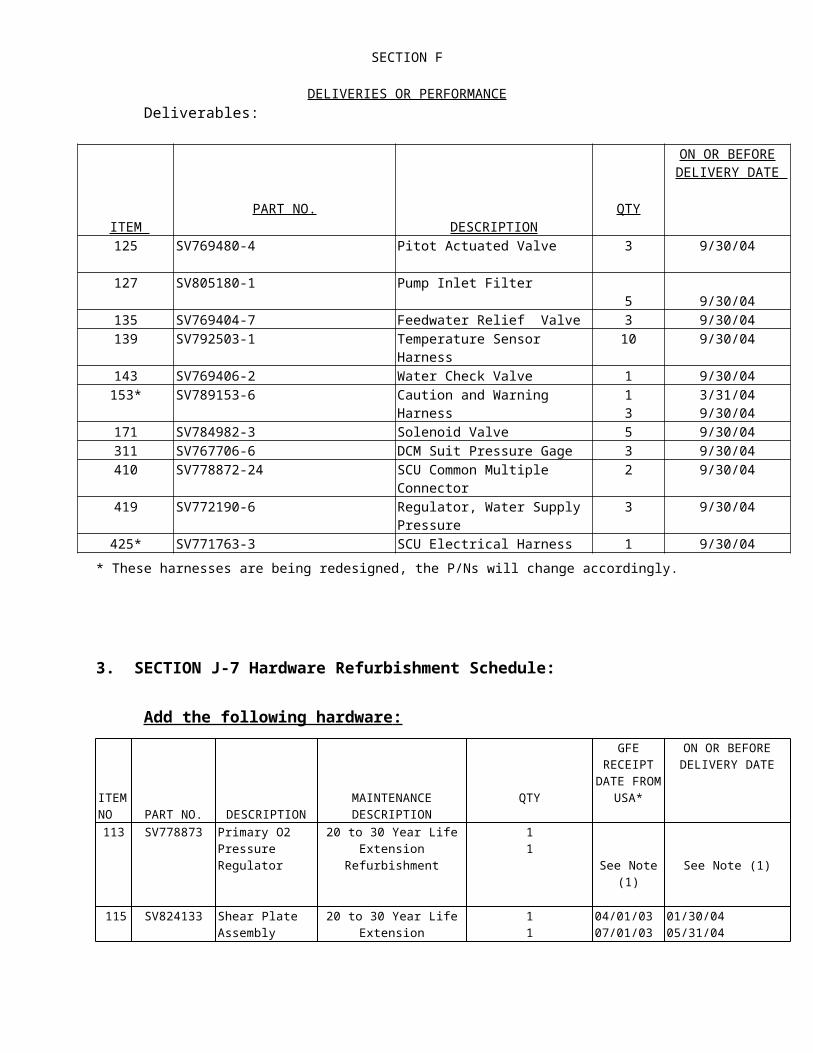
JSC DATA REQUIREMENTS LIST (DRL)
a. Title of Contract, Project, SOW, etc. b. Contract/RFP No. c. DRL Date/Mod DateEMU Program Contract NAS 9-97150 3/21/97
1. Line item no.
2. DRD Title 3. Frequency 4. As-of-Date
5. 1st subm. date
6. Copies
a. type 1
b. number53 Waiver/Deviation Request AR Print: 5
Electronic: 17. Data type: X (1) Written approval (2) Mandatory Submittal (3) Submitted upon request
8. Distribution (Continue on a blank sheet if needed) 9. RemarksTechnical Manager Data CenterContracting Officer SR&QASSM S&MA
Submit as part of CCBD.
1. Line item no. 2. DRD Title 3. Frequency 4. As-of- 5. 1st subm. 6. a. type b. number54 Geographic Economic Impact Reports Annually Print: 2
Electronic: 17. Data type: (1) Written approval X (2) Mandatory Submittal (3) Submitted upon request
8. Distribution (Continue on a blank sheet if needed) 9. RemarksContracting OfficerResource Analyst
Beginning of calendar year.
1. Line item no. 2. DRD Title 3. Frequency 4. As-of- 5. 1st subm. 6. a. type b. number55 Small Business, Women-Owned Small Business
and Small Disadvantaged Business concerns Plan/Reports
See 9 Print: 1Electronic: 1
7. Data type: (1) Written approval X (2) Mandatory Submittal (3) Submitted upon request8. Distribution (Continue on a blank sheet if needed) 9. RemarksContracting Officer SF294 - Semi-annually
SF295 - Quarterly
1. Line item no. 2. DRD Title 3. Frequency 4. As-of- 5. 1st subm. 6. a. type b. number56 Material Usage Agreement (MUA) AR Print: 3
Electronic: 17. Data type: (1) Written approval X (2) Mandatory Submittal (3) Submitted upon request
8. Distribution (Continue on a blank sheet if needed) 9. RemarksTechnical Manager S&MAData CenterMaterials
JSC Form 2323 (Rev May 91) (MS Word Aug 95)

JSC DATA REQUIREMENTS LIST (DRL)

JSC DATA REQUIREMENTS DESCRIPTION (DRD)
1. DRD Title 2. Current Version Date
3. DRL Line
RFP/Contract No.
PROGRAM MANAGEMENT PLAN 1/27/97 1 9-BL3-08-7-03P
4. Use (Define need for, intended use of, and/or anticipated results of data)This document shall be the master plan which describes the overall contractor system for the conduct and implementation of the contract statement of work.
5. DRD Category: (check one) Technical Administrative SR&QA6. References (Optional) 7. Interrelationships (e.g., with other DRDs) (Optional)CSD-SH-021, REV A8. Preparation Information (Include complete instructions for document preparation)
1. SCOPE: The Management Plan shall describe the basis for the contractor management organization, approach, and systems. It shall provide a comprehensive integration of all management systems of the prime, subcontractors, and major vendors. The systems will include those specifically required to accomplish the Statement of Work, as well as those systems and procedures that are to be set in place by the contractor.
2. CONTENT: The Management Plan shall address the contractor’s plans for work definition and authorization, scheduling, budgeting, data accumulation, Safety and Mission Assurance, Program recovery process, subcontract/material control, indirect cost management, baseline control, and organization structure.
This document shall be the master plan which describes the overall contractor system for the conduct and implementation of this program. The plan contents should be summary in nature but should provide sufficient information to define the concepts and techniques to be employed by the contractor in his approach to program management.
The plan shall consist of the requirements for each of the following areas and an index of the contractor’s internal operation plans, directives, and procedures for each of the following areas with a brief discussion as to how they will be utilized in managing the program and fulfilling the requirements:
a. Program Management b. Performance Management c. Configuration Management d. Risk Managemente. Data Managementf. Quality Assurance Managementg. Verification and Validation Management
Ref. h. Cleaning Test ManagementMod. 11 i. Reliability and Safety Management
j. Systems Engineering Management k. Project Engineering Management l. Subcontract Management m. Small Business Goals
n. Procurement Management o. Manufacturing Management
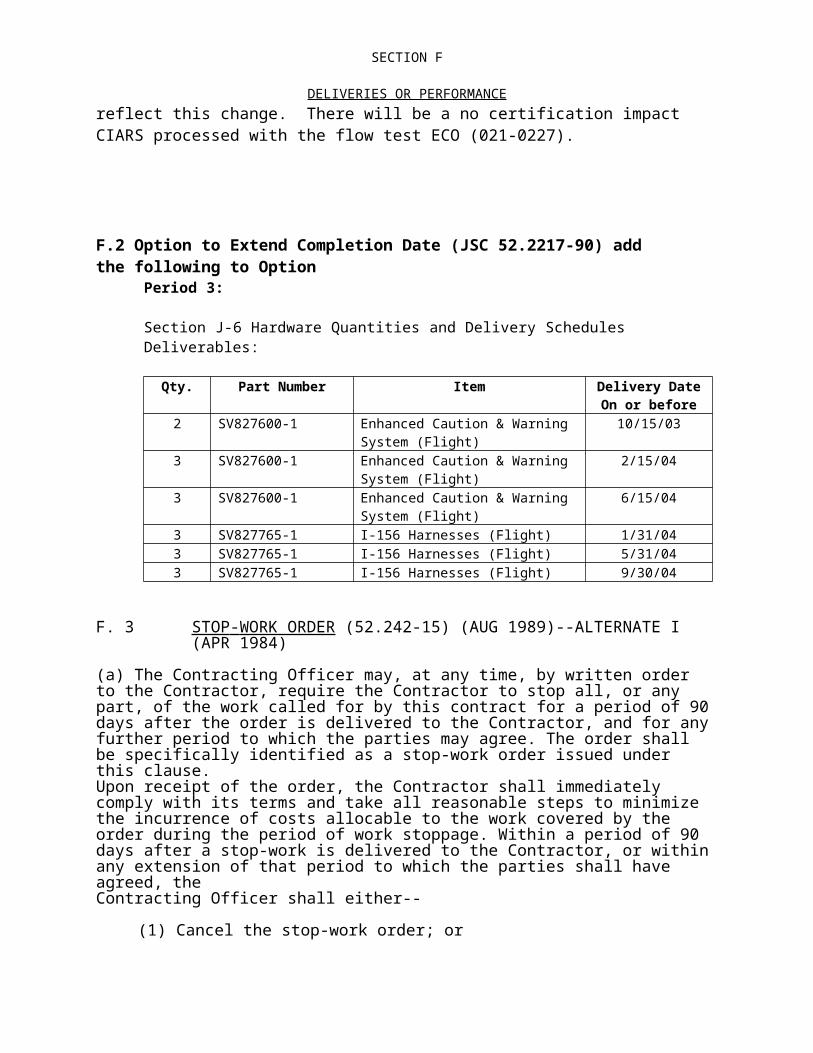
JSC DATA REQUIREMENTS DESCRIPTION (DRD)
p. Product Support Management q. Spares Logistics Management r. Transportation, Shipping, Receiving, Warehousing and Distribution Management
The contractor may add subject as deemed appropriate and necessary in order to convey his total program plan.
The plan shall include master phasing and milestone charts for the overall program which portray major milestones; e.g.,; beginning and completion of major activities; points at which major decisions must be made; and major action and events affecting the program requiring action by the Government as well as major subcontractors.
The plan shall include a current organization chart of that portion of your firm assigned responsibility for conducting the program. The chart shall show lines of authority and how the program fits within your corporate organization structure. In conjunction with this chart, the contractor shall identify by name the key management personnel in the functional areas of (a) Program Management; (b) Safety, Reliability, and Quality Assurance; (c) Systems Engineering; (d) Development; (e) Production; and (f) Product Support. Supporting documentation shall be furnished to show how you intend to blend the talents, skills, and experience of personnel in the various functional areas.
Upon NASA approval, the plan shall form the basis for the contractor’s overall program management system and shall be updated and submitted to NASA for approval as revisions are required.
This Data Requirement Description (DRD) establishes the requirement for the contractor to establish a detailed plan of operation for support at field sites.
This plan shall include, but not be limited to, the following:
a. Introduction - shall include the location and scope of operation for all support personnel.
b. Basic Requirements - shall describe the general approach to be used in implementation of this plan.
c. Management - shall describe the organization of the contractor and the field site personnel. This shall also include the general responsibilities of the field site personnel and the interfaces with NASA Safety, Reliability, and Quality Assurance (SR&OA) disciplines.
d. Data Control - shall describe the handling of technical documents, quality control documents, and engineering drawings by the field site personnel to ensure incorporation of all required changes with complete control and distribution thereof.
e. Control of Contractor-Acquired and Government-Furnished Property - shall describe the responsibilities and necessary steps in assuring Government property is received and maintained in good condition and repair in accordance with the Government-Furnished Property Clause.
f. Control of Contractor Fabricated Articles - shall describe the inspection and testing

JSC DATA REQUIREMENTS DESCRIPTION (DRD)
methods and procedures for fabricated articles.
g. Nonconforming Material Control - shall describe the various steps to take for nonconforming materials such as disposition of Discrepancy Reports (DR’s) follow-up action, recordkeeping, and requirements, etc.
h. Preservation, Packaging, Handling, Storing, and Shipping - shall describe the controls to be placed on these operations.
i. Training and Certification of Field Personnel - shall describe the training programs which shall be established to familiarize all concerned personnel with all equipment to which they may be exposed, methods of operation (with tests) showing personnel are certified by completion of training.
j. Data Reporting and Corrective Action - shall describe the responsibilities of personnel in relation to the collection, analysis, and follow-up of discrepancies and failures occurring in the field. This shall also include documents and records related to these discrepancies or failures.
k. Control of Ground Support Equipment (GSE) - shall describe the necessary steps and procedures to assure GSE is acceptable and maintained in good repair and that associated documentation is correct and properly maintained.
l. Testing - shall describe the responsibilities of personnel in support of all testing, requirements, and associated documentation is correct and properly maintained.
m. Logistics - shall describe personnel responsibilities in implementing all phases of logistics and associated documentation.
n. Engineering Data Center - shall describe the responsibilities of personnel and procedures used in establishing, storing, controlling, and distributing engineering data from a centrally established facility.
o. Spares - shall describe personnel responsibilities to ensure control and documentation of sparing requirements and that such documentation is maintained.
p. Other items as required.

JSC DATA REQUIREMENTS DESCRIPTION (DRD)(Based on JSC-STD-123)
1. DRD Title 2. Current Version Date
3. DRL Line Item No.
RFP/Contract No. (Procurement completes)
Work Breakdown Structure (WBS) and Dictionary
3/19/97 2 9-BL3-08-7-03P
4. Use (Define need for, intended use of, and/or anticipated results of data)The WBS and dictionary shall provide the framework for structuring the program implementation plans, establishing and tracking budgets, preparing schedules, developing work force and material estimates, preparing work authorization documents, and reporting contract performance.5. DRD Category: (check one) Technical Administrative SR&QA6. References (Optional) 7. Interrelationships (e.g., with other DRDs) (Optional)None None8. Preparation Information (Include complete instructions for document preparation)
1. SCOPE: The WBS shall encompass all the products required to achieve all the requirements of this contract. The WBS shall subdivide the work to be accomplished into elements that serve as the basis for detailed planning and control, and in addition, permit collection of cost and schedule data for each element.
2. APPLICABLE DOCUMENTS: None
3. CONTENTS: The WBS shall depict a family tree composed of all the work required by the contract. The dictionary contains a concise description of contract tasks to be performed an products to be delivered, subdivided by WBS element. A WBS element may represent an identifiable product, a set of data, a service, a task, or a budget function. The structure shall be at least at the level of detail in the RFP SOW with additional levels as required by the contract. Lower levels of detail, which the contractor uses for its own management purposes to validate information reported to NASA, shall be compatible with NASA requirements and be accessible to NASA. The relationship between the WBS and the contractor’s internal organizations and processes should also be provided.
4. FORMAT: The WBS tree is to be in organization chart format and the associated WBS narrative (WBS Dictionary) in text form an arranged as stated in “CONTENTS” of the DRD. The WBS tree and dictionary shall be provided in both electronic and hard copy form. Contractor shall conform to Government-approved style and layout formats per DRD 6 - Data Management Plan, or per Contracting Officer approval. Electronic data shall be formatted and delivered as the approved by the Contracting Officer. In case where format requirements conflict, Contractor shall obtain resolution from Contracting Officer.
5. MAINTENANCE: The WBS and WBS Dictionary shall be updated to reflect contract changes as they affect the WBS coverage. Revisions shall be incorporated by change page or complete reissue.
(Continue on a blank page if necessary)JSC Form 2341 (Rev Dec 91) MS Word (Aug 95)
J-1-196

JSC DATA REQUIREMENTS DESCRIPTION (DRD)(Based on JSC-STD-123)
1. DRD Title 2. Current Version Date
3. DRL Line
RFP/Contract No.
EARNED VALUE - FINANCIAL MANAGEMENT REPORT
1/23/97 3 9-BL3-08-7-03P
4. Use (Define need for, intended use of, and/or anticipated results of data)
Earned value reporting will provide contract performance and financial data to NASA in support of its insight responsibilities. 5. DRD Category: (check one) Technical Administrative SR&QA6. References (Optional) 7. Interrelationships (e.g., with other DRDs) (Optional) NPG 9501.2C; HSPPCS-TS6041 8. Preparation Information (Include complete instructions for document preparation)
1. SCOPE :
The contractor shall measure, analyze, and report EMU Program cost, schedule, and performance data on an earned value basis throughout the contract period of performance. Earned value reporting shall consist of integrate financial and performance measurement data which fully describes the interrelationship of these performance measurement variables. Variance analysis and recommended corrective action shall be provided for all unfavorable monthly cost and schedule variances with a value greater than 5% and $150K. Variance at completion analysis and recommended corrective action shall be required for all unfavorable cumulative variances with a value greater than 5% and $250K. Earned value reporting data shall correlate to all other contractor generated performance generated reporting and measurement reports.
2. CONTENT :
The contractor shall prepare financial management and performance measurement data in accordance with the NASA Contractor Financial Management Reporting, NASA Procedures and Guidelines (NPG) 9501.2C, (Current Version) and Hamilton Standard Program Planning Control System TS6040, respectively. Earned value data shall be reported on a cumulative basis from contract inception under each contract arrangement including Cost-Plus-Award-Fee, Cost-Plus-Incentive-Fee, and Cost-Plus-Fixed-Fee (Carry-Over).
Earned value reporting shall include, but not be limited to:
1. Baseline Program plans and schedules, as amended.2. Actual cost performance data measured against the contract value including
undefinitized contract actions, and against the budgeted cost of work performed. 3. Cost and man hour loading projections which demonstrate that resources are
adequate to meet program schedules requirements.4. Planning, monitoring, and controlling data used to manage program resources.
The data contained in the earned value reports must be auditable using Generally Accepted Accounting Principles. All supplemental cost performance reports submitted by the contractor will be reconcilable to the Earned Value Report. All costs will be reported on an accrual basis -
(Continue on a blank page if necessary)JSC Form 2341 (Rev Dec 91) MS Word (Aug 95)
J-1-197

JSC DATA REQUIREMENTS DESCRIPTION (DRD)(Based on JSC-STD-123)
cost to be reported in the period in which benefits are received without regard to time of payment.
3. FORMAT : - Earned Value Report Format
Column 7a (Budgeted Cost of Work Scheduled for the month) and 8a (Cumulative Budgeted Cost of Work Scheduled on Format 1) of the Earned Value Report represent the negotiated baseline plan for the contract. There may not be a relationship between the estimates provided in columns 7a and 8a of the Earned Value Report to columns 9a and 9b. Columns 7a and 8a represent the negotiated contract baseline plan plus all definitized contract changes.
Column 7a (Budgeted Cost of Work Scheduled for the month) and 8a (Cumulative Budgeted Cost of Work Scheduled on Format 2) of the Earned Value Report represent the performance measurement baseline for the contract. There may not be a relationship between the estimates provided in columns 7a and 8a of the Earned Value Report to columns 9a and 9b. Columns 7a and 8a represent the performance measurement baseline which includes all directed activity. Format 2 of the Earned Value Report will only include data associated with development tasks.
Short and long-term cost estimates, which include all data entered in columns 9a, 9b, and 10b on the Earned Value Report, shall be based on the most current and reliable information available.
Prior period cost adjustments should be reported in column 7c and 8c of Earned Value Report with a footnote discussing the reasons for and amounts of the adjustments.
Monthly earned value reporting is no longer required once the contract is physically complete, provided the final cost report includes actual cost only (no estimates or forecasts). The contractor must continue to submit monthly Earned Value Reports as long as estimates for the following period are included. If the final cost of a contract changes after the submission of the “final” contractor cost report, the contractor must submit a revised Earned Value Report in the month the cost change is recognized.
Earned value reporting shall be in Microsoft Excel format (numeric data) and Microsoft Word format (text) or a similar format which is accessible to NASA.
(Continue on a blank page if necessary)JSC Form 2341 (Rev Dec 91) MS Word (Aug 95)
J-1-198

JSC DATA REQUIREMENTS DESCRIPTION (DRD)(Based on JSC-STD-123)
1. DRD Title 2. Current Version Date
3. DRL Line
RFP/Contract No.
METRICS PACKAGE 1/27/97 4 9-BL3-08-7-03P
4. Use (Define need for, intended use of, and/or anticipated results of data)To provide the contractor’s plan for measuring key aspects of the EMU Program contract effort.
5. DRD Category: (check one) Technical Administrative SR&QA6. References (Optional) 7. Interrelationships (e.g., with other DRDs) (Optional)
DRD 1- Program Management Plan8. Preparation Information (Include complete instructions for document preparation)
1. SCOPE:
This document provides a description of the measurements that the contractor will use to manage the EMU Program contract including Program and Business Management, Engineering, hardware provisioning EUM enhancements, AEA Program implementation, and Safety, Mission, Assurance, and Product Assurance.
2. APPLICABLE DOCUMENTS:
JSC-36112 DA3 Development Project Metrics HandbookJSC-26010 DA3 Software Sustaining Engineering Metrics HandbookJSC-26458 DA3/SSO Sustaining and Operations Performance Management Metrics Handbook.
3. CONTENTS:
The Metric’s Package shall contain:
a. Metric description and rationaleb. Definition of supporting termsc. Mechanics of collecting and reporting the informationd. Correlation to other performance based reporting requirements - e.g.
Earned Value Report
4. FORMAT : - Contractor’s format is acceptable
5. MAINTENANCE: - Changes shall be incorporated as required, by change page or complete reissue
(Continue on a blank page if necessary)JSC Form 2341 (Rev Dec 91) MS Word (Aug 95)
J-1-199

JSC DATA REQUIREMENTS DESCRIPTION (DRD)(Based on JSC-STD-123)
1. DRD Title 2. Current Version Date
3. DRL Line Item No.
RFP/Contract No.
CONFIGURATION MANAGEMENT PLAN 1/27/97 5 9-BL3-08-7-03P
4. Use (Define need for, intended use of, and/or anticipated results of data)To describe the methods used in assuring proper configuration identification, control, and accounting during the program.
5. DRD Category: (check one) Technical Administrative SR&QA6. References (Optional) 7. Interrelationships (e.g., with other DRDs) (Optional)CSD-SH-021, REV. A8. Preparation Information (Include complete instructions for document preparation)
1. SCOPE: The contractor shall prepare and submit a Configuration Management Plan, which shall include the information necessary to demonstrate the understanding of configuration management. The plan shall detail the methods to be used in implementing configuration management during the program. The contractor shall define the methods described above in accordance with the provisions of CSD-SH-021. In addition, satisfaction of all requirements of the applicable documents shall be addressed within the Configuration Management Plan.
NOTE: Any desired deletions, modifications, etc., to these sections to make them appropriate for the program shall be outlined in the plan, as exceptions, for the procuring activity approval.
2. CONTENT: The contractor shall prepare and submit a Configuration Management Plan which shall conform, in general, to the following format. Deviations may be made to this format, and paragraphs shown may be further divided to more clearly present applicable procedures.
a. CONFIGURATION MANAGEMENT PLAN FORMAT
INTRODUCTION
1.0 PURPOSE
1.1 SCOPE
3.0 ORGANIZATION
Figure 1 Corporate OrganizationFigure 2 Organization of the Contractor’s EMU Program OfficeFigure 3 Organization of the Contractor’s EMU Configuration Management
Office
4.0 BASELINE CONTROLFigure 4 Baseline Management
5.0 SPECIFICATIONS/ASSEMBLY DRAWINGS AND DRAWINGS
(Continue on a blank page if necessary)JSC Form 2341 (Rev Dec 91) MS Word (Aug 95)
J-1-200

JSC DATA REQUIREMENTS DESCRIPTION (DRD)(Based on JSC-STD-123)
5.1 INTERFACE CONTROL
7.0 CONFIGURATION CONTROL
7.1 CONFIGURATION IDENTIFICATION
9.0 CONFIGURATION ACCOUNTING
9.1 SUBCONTRACTOR/VENDOR CONTROL
9.2 VERIFICATION MANAGEMENT
b. CONFIGURATION MANAGEMENT PLAN CONCEPT
1.0 PURPOSE
This section shall establish the purpose of the plan.
2.0 SCOPE
This section shall establish the scope of the contractor plan related to the contract, the contractor, and the end items to be controlled. This section shall include a specification list.
3.0 ORGANIZATION
3.1 Organizational Structure
The contractor shall prepare an organizational chart which illustrates the corporation structure for program management. The chart, either through the use of detailed narrative description or flow diagrams, shall illustrate the functional relationships in meeting the expressed contractual requirements. These organizational charts shall portray the contractor’s in-house design change control board or group and their relationship with other processing elements.
3.1.1 Relationship to Program Manager
The contractor shall present a description of the relationship of the Program Manager to the Configuration Management Organization indicating a direct line of authority to act for him in matters concerning configuration management.
3.2 Breakout and Responsibilities
The contractor shall identify the membership representation requirements within the in-house design control group as well as the lines of authority and responsibility. The control and
(Continue on a blank page if necessary)JSC Form 2341 (Rev Dec 91) MS Word (Aug 95)
J-1-201

JSC DATA REQUIREMENTS DESCRIPTION (DRD)(Based on JSC-STD-123)
administration shall indicate the relationship of change control to specification/assembly drawing preparation, engineering release ECP preparation, configuration management design reviews, first article configuration inspection, and configuration inspection, and configuration indexing and accounting.
3.3 Policy Directives
The contractor shall reference or incorporate those policies or policy directives which ensure the implementation of the configuration management program in accordance with contractual coverage. Specific management directives generated by this program shall be referenced. This plan shall indicate how planned directives are to accomplish an effective configuration management program and how management decisions are to be made in regard to engineering or design change.
4.0 BASELINE CONTROL
The contractor’s understanding of the baseline established and how the control techniques apply to these three baselines shall be described. The plan shall indicate a thorough understanding of the relationship of the specification/assembly drawings to configuration management, and demonstrate an adequate engineering release system to control these baselines. Reference shall be made to the requirements of the engineering release record requirements system of Section 6.0 with Sections 2.0 and 3.0 of CSD-SH-021.
4.1 Design Requirements Baseline
The contractor shall indicate an understanding of the design requirements baseline established at the beginning of the design phase and describe an intention to control changes to this baseline until CDR.
4.2 Certification Configuration Baseline
4.3 The plan shall show an understanding of the certification configuration baseline established at CDR and describe configuration management constraints and control of changes to this baseline until the product configuration baseline.
4.4 Product Configuration Baseline
4.5 The plan shall show the requirement for the normal configuration management constraints and an understanding of the exact meaning
(Continue on a blank page if necessary)JSC Form 2341 (Rev Dec 91) MS Word (Aug 95)
J-1-202
JSC DATA REQUIREMENTS DESCRIPTION (DRD)(Based on JSC-STD-123)
of the requirements in the specification part of the Specification/Assembly Drawing, drawings, and documentation. The contractor shall describe the control of changes to this baseline.
5.0 SPECIFICATION/ASSEMBLY DRAWINGS AND DRAWINGS
5.1 Engineering Drawings
The contractor’s understanding of the requirement to prepare engineering drawings in accordance with DOD-1000 and CSD-SH-021 and how reidentification and identification are related to the configuration management process shall be presented. The contractor shall also indicate his understanding of the interrelationship of the drawing system with the engineering release records described in Section 6.0 and with the identification requirements included in Sections 4.0 and 5.0 of CSD-SD-021.
5.2 Specification/Assembly Drawing
The contractor shall present an understanding of the specification/assembly drawing requirements for this program with particular emphasis on the end item specification/assembly drawing and how it is approved and updated, along with an understanding of the detailed end item specification/assembly drawing preparation and use.
6.0 INTERFACE CONTROL
The contractor’s understanding of how to accomplish the control of interface with the associated contracts and the integrating contractor on this program shall be presented.
6.1 Specification/Assembly Drawing Role
The plan shall provide for control of the interface through the specification / assembly drawing as established in CSD-SH-021. This shall include a discussion of the procedures required to control the end item detail specification/assembly drawings of Section 2.0 after the establishment of the product configuration baseline on how the interfaces are to be controlled through the hardware. The plan shall further establish the means for providing joint operating agreements with associated contractors which describe the interface requirements and relationships. This description shall include a requirement for integration of the various baselines between the associated contractors and, further the means, of communication to be used.
6.2 Role of Specification/Assembly Drawing Maintenance in Interface
(Continue on a blank page if necessary)JSC Form 2341 (Rev Dec 91) MS Word (Aug 95)
J-1-203

JSC DATA REQUIREMENTS DESCRIPTION (DRD)(Based on JSC-STD-123)
Control
The contractor shall describe an understanding of the specification/assembly drawing maintenance system of Section 2.0 and how the contractor design organization plans to use the specification/assembly drawing identification index as a working tool for review of interface changes. The contractor shall further describe how interface changes are to be jointly submitted between the associated contractors.
7.0 CONFIGURATION CONTROL
The contractor shall indicate the objectives for establishment, implementation and control coordination and/or approval of Class I, Class II, and Class III changes to contractor end items. He will indicate contractor change control procedures for in-house and field changes to EMU Hardware and specification/assembly drawing management.
8.0 CONFIGURATION IDENTIFICATION
The contractor shall indicate his method of configuration identification relative to assignment of identification numbers, use of the Engineering Release System, and formal reviews.
8.1 Role of the Index
The contractor shall detail the role and the purpose of configuration identification. The contractor shall describe a planned use of this method as a working tool in the control of the configuration. This shall also contain an understanding of the meaning of Sections 9.0 and 10.0 of CSD-SH-021 as related to contractor requirements.
8.2 Role of Configuration Accounting
The contractor’s plan shall describe an intention of implement the updating of the configuration accounting report and the internal means that are available to ensure incorporation of changes into the hardware. Also presented shall be the establishment of the joint operating agreements with the procuring activity and associated contractors whereby configuration identification and status accounting of all systems and end items are reviewed and reported expeditiously.
9.0 SUBCONTRACTOR/VENDOR CONTROL
The contractor shall indicate his proposed system from control over subcontractors and vendors. Particular emphasis shall be placed on the selection of subcontractors/vendors for their capability to support the
(Continue on a blank page if necessary)JSC Form 2341 (Rev Dec 91) MS Word (Aug 95)
J-1-204

JSC DATA REQUIREMENTS DESCRIPTION (DRD)(Based on JSC-STD-123)
requirements of configuration management. This shall include the requirement to comply with drawing and data requirements specified in CSD-SH-021. Provisions for review and approval of all Class I, Class II, and Class III changes of the subcontractor shall be included.
10.0 VERIFICATION MANAGEMENT
The plan shall describe the contractor’s program to ensure and demonstrate that the hardware/software processing requirements have been correctly implemented and to ensure and demonstrate that the hardware/software as-built configuration is in accordance with the approved requirements documents and the approved engineering. The plan shall also describe how identified “deltas” between the approved requirements/engineering will be handled including documenting the authority for any approved deltas.
The plan shall describe the contractor’s verification policies, procedures, implementation approach, and control systems that are to be used to ensure proper performance of all required contract VM activities. In addition, satisfaction of all the requirements of NSTS 07700, Volume XI shall be addressed within the VM plan.
EXHIBITS
The contractor may incorporate, as necessary, exhibits which will detail the requirements of the sections above. The exhibits shall provide sufficient insight into the contractor’s operating methods and controls which shall conform to the referenced or related documents or DRD/DRL’s.
(Continue on a blank page if necessary)JSC Form 2341 (Rev Dec 91) MS Word (Aug 95)
J-1-205
JSC DATA REQUIREMENTS DESCRIPTION (DRD)(Based on JSC-STD-123)
1. DRD Title 2. Current ersion Date
3. DRL Line
RFP/Contract No.
DATA MANAGEMENT PLAN 1/27/97 6 9-BL3-08-7-03P
4. Use (Define need for, intended use of, and/or anticipated results of data)To outline the contractor's planned method for preparation, release, change, revision, and control of data prepared in the performance of the contract5. DRD Category: (check one) Technical Administrative SR&QA6. References (Optional) 7. Interrelationships (e.g., with other DRDs) (Optional)CSD-SH-021, Rev. A8. Preparation Information (Include complete instructions for document preparation)
1. SCOPE:
This DRD delineates the requirements for the preparation of the contractor's Data Management Plan for management of all data generated under the contract.
2. CONTENT :
REQUIREMENTS
The plan shall contain details of the methods and procedures to be used to satisfy contractually imposed documentation requirements, including electronic mail, scheduling system, documentation system, budget planning, engineering databases, teleconferencing/video conferencing. The plan shall include policy and controls reflecting administrative and management approaches as well as detailed instructions for the handling of the data as defined herein. The plan shall include the following data management elements as a minimum:
a. Methods and procedures for providing EMU contract “look-In” capabilities including the real-time implementation of all contract changes.
b. Methods for management and control of data elements presented on the DRL as well as internal documents used in the performance of the contract, including internal distribution and control, external controls, schedules monitoring to assure timely deliveries of data, and the submittal of these schedules in the monthly progress report.
c. Methods and procedures for assuring implementation of data requirements on subcontractors / vendors to assure attainment of overall document objectives.
d. Methods and procedures for identification, definition, and justification of new data requirements. Requirements shall be the minimum necessary to satisfy the discipline requirements. Redundant requirements shall be combined in one document when practicable. The contractor's methods for reviewing and monitoring existing data for continuing needs shall be included.
(Continue on a blank page if necessary)JSC Form 2341 (Rev Dec 91) MS Word (Aug 95)
J-1-206

JSC DATA REQUIREMENTS DESCRIPTION (DRD)(Based on JSC-STD-123)
e. Organizational structure of the contractor's data management system, including responsibilities and lines of communication with the Program Manager and related disciplines.
f. Procedures for recall, replacement or change to released drawings, process specifications or other data to assure latest or proper documentation is being used during manufacture, test, maintenance, etc.
g. Methods and procedures for generating each DRL data requirement.
DEFINITIONS
The following definitions contain requirements applicable to JSC contractors:
a. Basic Issuance. Refers to the initial approved issuance of a drawing, specification assembly/drawing, or document.
b. Change. An official correction to a document resulting from changed conditions or from more complete information.
c. Change Sheet. A device for formally transmitting changes in content or corrections to an existing document.
d. Revision. A major change, extensive enough to require retype, reprint, and reissuance of an entire document. Revisions shall not normally be required or justified since the Document Change Notice (DCN) and Engineering Change Order procedures in CSD-SH-021 are designed to adequately reflect changes. No document revisions shall be prepared without the approval of the NASA JSC/CSD Data Manager.
e. Supplement. A collection of data, printed or otherwise, providing more detailed information on the subject of the basic document. Supplements may be too voluminous to be included in the general distribution of a document. Supplements, when printed and included in a document, will be a volume or part of the basic document.
DOCUMENT MAINTENANCE
a. Change sheets shall be prepared for each change.
b. Revisions shall require data manager approval, as stated in DEFINITIONS, paragraph d. Revision of this DRD. Revisions, when approved, shall be prepared in the same manner as basic documents. Previously modified page, paragraph and figure numbers, as well as previous change symbols, shall be eliminated. Change symbols shall identify new or revised material in the table of contents.
PROCEDURAL DOCUMENTS
(Continue on a blank page if necessary)JSC Form 2341 (Rev Dec 91) MS Word (Aug 95)
J-1-207
JSC DATA REQUIREMENTS DESCRIPTION (DRD)(Based on JSC-STD-123)
Documents containing procedures which require entry of accomplishment of observed values shall be prepared using test data sheets, prepared as attachments or prepared using the test Preparation Sheet in accordance with the DRL.
(Continue on a blank page if necessary)JSC Form 2341 (Rev Dec 91) MS Word (Aug 95)
J-1-208
JSC DATA REQUIREMENTS DESCRIPTION (DRD)(Based on JSC-STD-123)
1 DRD Title 2. Current Version Date
3. DRL Line
RFP/Contract No.
GOVERNMENT PROPERTY MANAGEMENT PLAN
1/27/97 7 9-BL3-08-7-03P
4. Use (Define need for, intended use of, and/or anticipated results of data)To describe the method of administering government real and personal property.
5. DRD Category: (check one) Technical Administrative SR&QA6. References (Optional) 7. Interrelationships (e.g., with other DRDs) (Optional)
8. Preparation Information (Include complete instructions for document preparation)
1. SCOPE: The Government Property Management Plan defines the contractor’s use, maintenance, repair, protection, and preservation of Government real and personal property.
2. APPLICABLE DOCUMENTS:
Federal Acquisition Regulation (FAR) Part 45NASA FAR Supplement (NFS) Part 1845NMI 4000.3 Supply and Equipment ManagementNHB 4100.1 NASA Materials Inventory Management ManualNHB 4200.1 NASA Equipment Management Manual User’s Handbook for
Property CustodiansNHB 4300.1 NASA Personal Property Disposal Manual
3. CONTENTS:
This plan shall consist of those procedures which constitute the contractor’s Property Management Manual and shall include at a minimum the following categories:
a. Property management i. Reportsb. Acquisition j. Consumptionc. Receiving k. Utilizationd. Identification l. Maintenancee. Records m. Subcontractor controlf. Movement n. Dispositiong. Storage o. Contractor close-outh. Physical Inventories p. Reconcile contractor records with
NASA’s financial records
4. FORMAT: Contractor format is acceptable.
5. MAINTENANCE:
(Continue on a blank page if necessary)JSC Form 2341 (Rev Dec 91) MS Word (Aug 95)
J-1-209

JSC DATA REQUIREMENTS DESCRIPTION (DRD)(Based on JSC-STD-123)
Changes shall be incorporated as required by change page or complete reissue.
(Continue on a blank page if necessary)JSC Form 2341 (Rev Dec 91) MS Word (Aug 95)
J-1-210

JSC DATA REQUIREMENTS DESCRIPTION (DRD)(Based on JSC-STD-123)
1. DRD Title 2. Current Version Date
3. DRL Line
RFP/Contract No.
LOGISTICS OPERATIONS REPORTING 1/27/97 8 9-BL3-08-7-03P
4. Use (Define need for, intended use of, and/or anticipated results of data)To monitor the volume of logistics activity onsite and off-site including contractor Government Owned Property reporting.
5. DRD Category: (check one) Technical Administrative SR&QA6. References (Optional) 7. Interrelationships (e.g., with other DRDs) (Optional)NHB 4100.1B NFSD Part 18-52.245 and Alternate #18. Preparation Information (Include complete instructions for document preparation)
I. On-Site Logistics Operations Reporting
The following reports are required to be prepared when onsite storage of material exceeds $20,000 for stores stock or $75,000 for program stock in one location (such as a storeroom):
1. Material Inventory Report (Line Items) - This semiannual report defines the following data elements as of March 15 and September 15 of each year: Total number of line items; total number of receipts during the past 6 months; total number of issues in the last 6 months; new line items added to the inventory; and items from inventory stock deleted since the last report.
2. Material Inventory Report (Dollar Value) - This semiannual report defines the following data elements as of March 15 and September 15 of each year: Starting price; price of receipts; price of issues; and ending price.
NOTE: This will be broken out by each Object Class code stocked in the storeroom. (See the JSC Stores Stock Catalog preface for a detailed explanation of these codes.)
3. Logistics Personnel Resources - This semiannual report identifies the number of man-hours expended by the contractor in their logistics functions: Equipment Management; NASA Equipment Management System (NEMS) Planning and Analysis; and Supervision. Productive man-hours only are to be shown. This report is to also include any off-site man-hours that may be devoted to operation of the onsite storeroom(s). The information required in this report applies only to those personnel who spend more than 50 percent of their time in support of onsite logistics operations.
4. Physical Inventory of Material Report - This report identifies the sampling inventory actions completed by the contractor. This report contains the following data by Object Class code: Line items and dollar value of items inventories; number of line items with variances; and dollar value of discrepant items, including overages, shortages, and gross discrepancies. This report shall also identify whether
(Continue on a blank page if necessary)JSC Form 2341 (Rev Dec 91) MS Word (Aug 95)
J-1-211

JSC DATA REQUIREMENTS DESCRIPTION (DRD)(Based on JSC-STD-123)
inventoried items are stores, program, or standby stock, and it will also identify the staff hours and dollar value expended in accomplishing and reconciling the inventory.
The report will also contain a brief explanation as to why the discrepancies arose and what will be done to minimize the chance for recurrences.
NOTE: Reports 1 through 4 above are to treat Contractor-Acquired Material (CAM) and Government-Furnished Material (GFM) as one lot.
5. Quarterly Report of CAM - This report will consist of two transfer documents (DD Form 1149 or similar) that identify material purchased and received by the contractor for onsite use. The two documents will be differentiated as follows:
a. Items bought for direct consumption onsite.
b. Items issued to the storeroom(s) that will impact the dollar value of assets on-hand.
The DD Form 1149 will be transferring accountability of these assets to NASA and will be accompanied be either attaching copies of the acquisition documentation or by including a listing that includes: Purchase Order number national stock number or Model Number (quantity and unit total value of items received; and date of receipt. DD Form 1149 will identify total number of line items and total value.
NOTE: All of these reports are to be submitted in the JSC Property Administer, Mail Code JB3, and are due 15 days after fiscal year quarters.
6. Contractor with Stock Valued at $20,000 and Over - Submit quarterly report consisting of DD Form 1149 indicating value of balance ( as of first period), receipts, issue, and new balance ( as of last day of period). This should be submitted to the Contacting Officer and Supply and Equipment Management Officer.
II. Off-Site Logistics Operations Reporting
1. NASA Form 1018, “Financial Reporting of NASA Property in the Custody of Contractors,” must be delivered to the JSC Financial Management Officer no later than October 5 of each year. The effective date of the report is to be September. See 18 -52.245.73 (September 1996)
2. Report of Offsite Physical Inventory Performance. Due annually (within 30 calendar days of inventory completion). This report will provide the date of inventory completion, discrepant line items discovered during the physical inventory, and summaries of completed and in-process efforts. Where in-process actions are shown, a completion schedule will be included. The materials inventory adjustments must be reported on NASA Form 1256; the equipment inventory adjustments will be reported in a format mutually agreed upon by the contractor and the cognizant Property Administrator.
(Continue on a blank page if necessary)JSC Form 2341 (Rev Dec 91) MS Word (Aug 95)
J-1-212

JSC DATA REQUIREMENTS DESCRIPTION (DRD)(Based on JSC-STD-123)
(Continue on a blank page if necessary)JSC Form 2341 (Rev Dec 91) MS Word (Aug 95)
J-1-213

JSC DATA REQUIREMENTS DESCRIPTION (DRD)(Based on JSC-STD-123)
1. DRD Title 2. Current Version Date
3. DRL Line
RFP/Contract No.
NEW TECHNOLOGY REPORT 1/27/97 9 9-BL3-08-7-03P
4. Use (Define need for, intended use of, and/or anticipated results of data)Provides NASA with technical information relating to the contractor's Technology Transfer Policy and Plan concerning any invention, discovery, improvement, or innovation made by a contractor in the performance of work under this contract for the purpose of disseminating this information to obtain increased use.
5. DRD Category: (check one) Technical Administrative SR&QA6. References (Optional) 7. Interrelationships (e.g., with other DRDs) (Optional)
8. Preparation Information (Include complete instructions for document preparation)
1. SCOPE:
The contractor shall submit New Technology Reports pertaining to activities conducted under the contractor's Technology Transfer Plan. These reports shall include technical detail as is necessary to identify and fully describe all "Reportable Items." These reports shall include all technology transfer activities that identify promising technologies having dual-use application developed under this contract.
2. APPLICABLE DOCUMENTS:
NFS 18-52.227-70 New Technology ClauseFAR 52.227-11 Patent Rights - Retention by Contractor (Short Form) (June 1989) - as modified by NASA FAR Supplement 1852.227-70
3. CONTENTS:
The report shall be limited to the following elements as appropriate. The report shall be accompanied by a copy of NASA Form 666A (April 1985) completed in accordance with instructions on the reverse of the form. Use of this form is optional, provided all information listed below is included in each report:
a Name and address of the contractor submitting the report.
b The contract number of the contract under which the report is being submitted.
c Title of the item reported.
d Brief (abstract) description of the item reported.
e Detailed description in the following order:
1) General purpose of the item (if not explained in the abstract description).
(Continue on a blank page if necessary)JSC Form 2341 (Rev Dec 91) MS Word (Aug 95)
J-1-214

JSC DATA REQUIREMENTS DESCRIPTION (DRD)(Based on JSC-STD-123)
2) Improvement and/or advantage over prior methods materials, or devices.
3) Principle of operation of device, details of the preparation of the process and/or materials, etc. Technical data, drawings, and sketches should be included as required to fully describe the item.
4) Feature of the item believed to be new.
5) Additional information needed to fully describe the item.
f. APPLICATIONS: Include possible industrial and other non-aerospace users. Identify specific industries, processes, or products in which the "Reportable Item" might find application or to which it might be related.
g. Description of possible extensions of this item.
h. Degree of development. Indicate applicable stage:
1) Concept only.2) Development completed, prototype available.3) Limited production.
i. Innovator's name(s) and social security number(s), mailing address, and telephone number.
j. Identification of any previous publication of the disclosure. List publications or reports pertaining to this item. If company-originated, state where they may be obtained; if not company-originated, indicate source and where publication may be obtained, if known.
k. Technical supervisor or innovator(s).
4. FORMAT:
The New Technology Reports shall bed in letter format commensurate with their intended use.
5. MAINTENANCE :
None required.
(Continue on a blank page if necessary)JSC Form 2341 (Rev Dec 91) MS Word (Aug 95)
J-1-215

JSC DATA REQUIREMENTS DESCRIPTION (DRD)(Based on JSC-STD-123)
(Continue on a blank page if necessary)JSC Form 2341 (Rev Dec 91) MS Word (Aug 95)
J-1-216

JSC DATA REQUIREMENTS DESCRIPTION (DRD)(Based on JSC-STD-123)
1. DRD Title 2. Current Version Date
3. DRL Line
RFP/Contract No.
EMU PROCESSING AND CONSTRAINTS DOCUMENT(FEMU-R-001)
1/27/97 10 9-BL3-08-7-03P
4. Use (Define need for, intended use of, and/or anticipated results of data)To provide processing/test requirements and information to the EMU processing contractor (FEPC)
5. DRD Category: (check one) Technical Administrative SR&QA6. References (Optional) 7. Interrelationships (e.g., with other DRDs) (Optional)
SEMU-43-001; SEMU-44-001; FEMU-R-0028. Preparation Information (Include complete instructions for document preparation)
1. The contractor shall prepare and submit a document covering the processing and between flight testing
of EMU hardware end items.
2. The document shall include, but not be limited to the following:
a. Special processing constraints unique to each end item.b. Ground test requirements for
1) Flight use2) Chamber use3) Post flight
c. Component change out retest requirement.d. Overall processing flow diagram.e. Detailed maintenance information on each EMU hardware end item.f. General information on WETF hardware maintenance.
3. This document must comply with the Volume X master verification plan for ground turnaround.
(Continue on a blank page if necessary)JSC Form 2341 (Rev Dec 91) (MS Word Aug 95) Page 217 of 8
JSC DATA REQUIREMENTS DESCRIPTION (DRD)(Based on JSC-STD-123)
1. DRD Title 2. Current Version Date
3. DRL Line
RFP/Contract No.
INTERFACE CONTROL DOCUMENTS (ICD)
1/27/97 11 9-BL-08-7-03P
4. Use (Define need for, intended use of, and/or anticipated results of data)Interface control documents shall be used to delineate the physical details and functional characteristics of an interface.
5. DRD Category: (check one) Technical Administrative SR&QA6. References (Optional) 7. Interrelationships (e.g., with other DRDs) (Optional)MIL-STD-100A8. Preparation Information (Include complete instructions for document preparation)
1. POLICY:
a This DRD establishes the requirement for preparation, review, approval, distribution, and subsequent revisions of interface control drawings or documents (ICD). This system of drawings, diagrams, facility construction drawings, and specifications shall record agreements between the contractor and the National Aeronautics and Space Administration (NASA).
b These data shall be prepared under instructions provided and in accordance with referenced documents above.
c The required drawings and documents shall show the configuration to which interfacing hardware is designed with the effectivity of that configuration specified. A change in design affecting existing interface agreements shall be added to the ICD.
d All contractor interface control documentation activity shall be coordinated internally. Contractor generated ICD’s will be added to specifications by formal change control.
e The contractor is responsible to ensure that all interface requirements of other contractors are properly documented and that such documentation is prepared, coordinated, and negotiated.
f Negotiations with NASA, or other contractors, required to obtain acceptance of the interface control agreement, shall be conducted by the contractor.
2. RELEASE:
a The contractor shall be responsible to ensuring the ICD’s are properly prepared and internally coordinated. He is further responsible for conducting all negotiations with NASA, and other contractors involved; these negotiations being required to obtain acceptance of interface control agreements.
b Following contractor review and approval of an ICD, and negotiations with the customer or with other contractors, the master of the ICD is to be forwarded to NASA, for their approval signatures. Such forwarding shall be by registered mail, “Return Receipt
(Continue on a blank page if necessary)JSC Form 2341 (Rev Dec 91) (MS Word Aug 95) Page 218 of 8

JSC DATA REQUIREMENTS DESCRIPTION (DRD)(Based on JSC-STD-123)
Requested.”
c The ICD shall be considered to be effective on the date of the final approval signature.
d The approved master is returned to the ICD originator for reviews for accuracy, completeness, etc., and a release letter, including a distribution list.
3. CONTENTS: The document shall contain the following, as applicable:
a Purpose and function of the interface.b Total system information flow across the interface.c Facility to systems interfaces—power, signal, grounding, physical, environmental, and
equipment layouts.d Data formats and data handling conventions between major systems and subsystem
interfaces, both hardware and software.e Physical and electrical characteristics between major systems and subsystem
interfaces logic levels, data rates, control mechanisms, timing, cable types, and impedence.
f Identification of applicable standards.g Identification of responsibilities of participating organizations.h Interface constraints.
ICD’s external to NASA shall be Data Type 1; all others shall be Data Type 2.
(Continue on a blank page if necessary)JSC Form 2341 (Rev Dec 91) (MS Word Aug 95) Page 219 of 8

JSC DATA REQUIREMENTS DESCRIPTION (DRD)(Based on JSC-STD-123)
1 DRD Title 2. Current Version Date
3. DRL Line
RFP/Contract No,
MASS PROPERTIES REPORT 2/5/97 12 9-BL3-08-7-03P
4. Use (Define need for, intended use of, and/or anticipated results of data)Present weight status, specification weights, current weights, changes, etc.
5. DRD Category: (check one) Technical Administrative SR&QA6. References (Optional) 7. Interrelationships (e.g., with other DRDs) (Optional)
8. Preparation Information (Include complete instructions for document preparation)
1. The contractor shall prepare a report in accordance with this DRD, which shall contain, but not be limited to, the following type of information: specification and current weights, current weight changes, discussion of changes, pending changes, problems, etc. As items progress from developmental to operational, individual status shall be shown as soon as the designs become distinguishable.
2. The format of these reports shall present the following minimum data:
a. Weight Summary Statement - per Sample Format ‘A’.
b. Current Change Analysis - A narrative discussion of significant changes. Number each change and cross reference changes to applicable entries in the Weight Summary Statement. Reference the authorization (letter, meeting, etc.) for each change. Identify changes previously listed as pending change. Reference drawing numbers of components changed.
c. Pending Changes - A narrative discussion of potential changes. Assign an identification number to each change. Changes should eventually be implemented or discarded. If implemented, reference identification number in Current Analysis. If discarded, retain identification number and note disposition. Reference the approximate date of item serial incorporated number when pending change will be
d. Discussion of Problem Areas.
(Continue on a blank page if necessary)JSC Form 2341 (Rev Dec 91) (MS Word Aug 95) Page 220 of 8

JSC DATA REQUIREMENTS DESCRIPTION (DRD)(Based on JSC-STD-123)
1. DRD Title 2. Current Version Date
3. DRL Line
RFP/Contract No.
CERTIFICATION PLAN / PROCEDURE/ REPORT
1/27/97 13 9-BL3-08-7-03P
4. Use (Define need for, intended use of, and/or anticipated results of data)To provide NASA/JSC with cognizance of the elements of the contractor's plan for hardware certification
5. DRD Category: (check one) Technical Administrative SR&QA6. References (Optional) 7. Interrelationships (e.g., with other DRDs) (Optional)ISO 90018. Preparation Information (Include complete instructions for document preparation)
1. The Certification Plan
The certification plan shall define the specific methods to be used to verify that the hardware meets the technical requirements of the applicable EMU hardware end item specification. When a method other than test is to be used, the specific method (i.e., stress analyses, thermal analyses, radiographic inspections, etc.) shall be identified, and the objectives of these methods shall be defined. The Certification Plan shall include the following as applicable:
a. Part name and number of the article being certified.
b. Serial and part numbers of drawing number of specimens to be tested.
c. Environments and life/cycle requirement.
d. Certification method (test, analysis, etc.) including sequence (include the supporting rationale when analysis is performed in lieu of test).
e. Environmental acceptance test requirements.
f. Statement of requirement for functional test prior to and following qualification test and list appropriate references.
g. Number of specimens and allocation to test.
h. Type of tests to be conducted.
i. Objective of the test.
j. Test duration.
k. Environmental and performance test condition (including pass/fail criteria and tolerance).
l. Operational mode of the equipment during test (on or off).
m. Retest requirement.
(Continue on a blank page if necessary)JSC Form 2341 (Rev Dec 91) (MS Word Aug 95) Page 221 of 8

JSC DATA REQUIREMENTS DESCRIPTION (DRD)(Based on JSC-STD-123)
n. Allowable maintenance during test.
o. Disposition of test specimen(s).
p. QTRR (qualification test readiness review) and QSA (qualification site approval).
Certification by test shall be in accordance with the specific contract requirements. Certification test hardware components which are to be disassembled after completion of testing for inspection (to determine margins of safety and potential failure modes) shall be identified in the Certification Plan.
Certification methods to verify that the hardware meets the technical requirements of the applicable EMU hardware end item specification shall be defined in a certification matrix which shall be prepared in accordance with the form shown in Figure 1 and included in the Certification Plan, except when the Plan is included in the specification Assembly Drawing.
2. Certification Procedure
This Data Requirement Description establishes the requirements for the preparation of Certification Test Procedures. The procedure format shall provide detailed documentation of all testing required to demonstrate that the item under test is in conformance with all applicable specification requirements.
The procedure shall contain a list of tests, sequence of tests, conditions to be established for each test, instrumentation requirements, detailed procedures to be followed in conducting each test, data recording requirements, values and tolerances required, and data sheets for recording values to be obtained. The procedure shall also contain a cross-reference to the applicable specification requirements governing the individual tests.
a. The procedure shall, in addition, include the following:
1) Assure the attainment of repeatable conditions both standard and simulated. 2) Establish and determine significant failure modes.3) Determine the effects of varied stress levels and performance parameter.4) Determine the effects of combinations of tolerances and drift of design parameters.
3. Certification Report
The report shall contain the formal certification data that is required to allow a hardware item to be certified. The report shall include complete results of the conducted tests and all analysis which were generated in lieu of test requirements.
a. The engineering analysis will contain:
1) Requirement definition.
2) Analysis objective.
(Continue on a blank page if necessary)JSC Form 2341 (Rev Dec 91) (MS Word Aug 95) Page 222 of 8

JSC DATA REQUIREMENTS DESCRIPTION (DRD)(Based on JSC-STD-123)
3) Analysis logic and details.
b. The test report shall include:
1) Test objective.
2) Test hardware description.
3) Test setup including photographs and drawings.
4) As-run test procedure with proper validations.
5) Failures, variance in hardware performance, departure from test procedure and anomaly details.
6) Test results and complete reduction of the test data; analysis and conclusions.
7) Laboratory notes with validation.
The certification report shall contain as a conclusion a formal certification recommendation. The certification plan shall be included as an appendix.
(Continue on a blank page if necessary)JSC Form 2341 (Rev Dec 91) (MS Word Aug 95) Page 223 of 8

JSC DATA REQUIREMENTS DESCRIPTION (DRD)(Based on JSC-STD-123)
1. DRD Title 2. Current Version Date
3. DRL Line
RFP/Contract No.
NASA EMU LSS & SSA DATA BOOK 1/27/97 14 9-BL3-08-7-03P
4. Use (Define need for, intended use of, and/or anticipated results of data)
To provide operational and technical information to assist in preparation of the Program Operations Handbooks.5. DRD Category: (check one) Technical Administrative SR&QA6. References (Optional) 7. Interrelationships (e.g., with other DRDs) (Optional)
8. Preparation Information (Include complete instructions for document preparation)
The contractor shall prepare and submit to NASA data pertaining to the description, operation and performance of all EMU hardware for which the contractor is responsible.
The following type of data shall be provided in the following areas:
a. Descriptive information, including pictorials and figures, about the EMU hardware and its subsystems.
b. Malfunction logic which encompasses the recognition, and diagnosis of system malfunctions.
c. Performance characteristics of the EMU hardware and its subsystems.
Narrative data shall be typed on 8.5” X 5.5” standard paper. Graphs, pictorials, and figures shall be of reproducible quality.
The data shall be transmitted in book form.
(Continue on a blank page if necessary)JSC Form 2341 (Rev Dec 91) (MS Word Aug 95) Page 224 of 8

JSC DATA REQUIREMENTS DESCRIPTION (DRD)(Based on JSC-STD-123)
1. DRD Title 2. Current
Version Date3. DRL
Line RFP/Contract No.
Safety & Mission Assurance Certification Approval Request (SMACAR)
016 Aug 96 15 9-BL3-08-7-03P
4. Use (Define need for, intended use of, and/or anticipated results of data)The SMACAR is the approval form for flight hardware certification.
5. DRD Category: (check one) Technical Administrative SR&QA6. References (Optional) 7. Interrelationships (e.g., with other DRDs) (Optional)
SAR8. Preparation Information (Include complete instructions for document preparation)
SCOPE: The SMACAR, with attached documentation, meets the information requirement for a certification approval request (CAR) as submittal and approval of the hardware certification. The SMACAR may serve as the certification report, when a formal certification report document is not submitted. The SMACAR may also serve as the certification requirements (CR), commonly documented in the program requirements document and the certification plan, when pre-approved as such.
CONTENTS: All sections shall be filled out unless they are marked N/A. As used in the SMACAR, “Test” document shows the test was done and verified. All documents listed in the SMACAR as verification of a requirement or specification must be attached to the SMACAR as part of this certification report.
FORMAT: The SMACAR was created using Microsoft Word for Windows 6.0. The form has also been converted for Macintosh Word 4.1. Conversion to other formats is available upon request. These forms and instructions are available upon request.
SAFETY & MISSION ASSURANCE CERTIFICATION APPROVAL REQUEST PageNASA - Johnson Space Center 225 of
Part Number Part Name System
Assemblies (Part Number | Part Name) for Certification and Shipping
Manifest Change Directiveand Board/Panel
Change Control Authority (Board Name)
Certification Plan
Requirements Document
ICD # CriticalityFunc/Hdwr
SSM/PE: Phone #: Mail Code:
# of 1st Limited Life Weight Dimensions FMEA/CIL Safety Analysis
(Continue on a blank page if necessary)JSC Form 2341 (Rev Dec 91) MS Word (Aug 95)
J-1-225

JSC DATA REQUIREMENTS DESCRIPTION (DRD)(Based on JSC-STD-123)
Missions Certified
Flight Document # Report Document #
Criticality Rationale Summary:
Does test hardware configuration differ from flight hardware configuration?Installation Information:
Mounted:
Locker Stowed:
Stowed Other:
Launch Location:
Crew Cabin:
Payload Bay:
Space Lab/Hab:
Other:
Landing Location: Same or list otherOperational Location:
Crew Cabin:
Payload Bay:
Space Lab/Hab:
Other:
General Operational Information:
Operational Performance Requirements:
Crew Procedures Data Book:Flight Rules (List all by FR# and Title):
Approvals:
Subsystem Manager Battery Manager
Materials Control Manager Structures
SR&QA Structures NS/Flight System Safety and Mission Assurance
JSC Form 1296
(Continue on a blank page if necessary)JSC Form 2341 (Rev Dec 91) MS Word (Aug 95)
J-1-226

JSC DATA REQUIREMENTS DESCRIPTION (DRD)(Based on JSC-STD-123)
SAFETY & MISSION ASSURANCE CERTIFICATION APPROVAL REQUEST PageNASA - Johnson Space Center 227 of
Part Number Part Name System
Materials: JSC Materials Certification Memorandum:(Signature Required if no Memo #)
MATL - MUA Numbers:
Materials compatible:
IVA:
EVA:
Other:
Electrical Interfaces: (List all power and signal interfaces to the Orbiter or other equipment, including battery size and type if applicable).Power Interface Location:(D&C Panel #)
Orbiter Circuit Protection:
Hardware Nominal Amps:
Bonding Verification:
Hardware Circuit Protection:
Batteries: Other:
Electromagnetic Compatibility Information: EMC/EMI TEST
24V to 32VDC Power Performance Test
Temperature Validation: QTT Range: QTT Test: Cycle
s:QTVT Range:
QTVT Test: Cycles:
Non-operating Temperature Limits:
Operating Temperature Limits:
Survivable Mission Operational Time Limit:Touch Temperature Test:
Acceptance Thermal:
(Continue on a blank page if necessary)JSC Form 2341 (Rev Dec 91) MS Word (Aug 95)
J-1-227

JSC DATA REQUIREMENTS DESCRIPTION (DRD)(Based on JSC-STD-123)
ATT Range: ATT Test: Cycles:
QATT Range:
QATT Test: Cycles:
ATVT Range:
ATVT Test:TPS
Cycles:
QATVT Range:
QATVT Test:
Cycles:
Structural Validation:Factor of Safety for Test: Factor of Safety for Analysis:Structural Integrity Verification Plan: Stress Analysis:Fracture Control Summary Report: Fracture Plan:QVT Amplitude:
QVT Test: Duration:
20G Crash Test:
Shock Test:
Limit Loads: Limit Loads Test:Life Cycles: Life Cycle Testing: Captive Fastener Cycle Life:
Fastener Life Traceability Per:
Pressure Systems:System Operational Pressure RangeProof Pressure:
Burst Pressure:
System Operational Pressure Range:
JSC Form 1296
(Continue on a blank page if necessary)JSC Form 2341 (Rev Dec 91) MS Word (Aug 95)
J-1-228

JSC DATA REQUIREMENTS DESCRIPTION (DRD)(Based on JSC-STD-123)
SAFETY & MISSION ASSURANCE CERTIFICATION APPROVAL REQUEST PageNASA - Johnson Space Center 229 of
Part Number Part Name System
Acceptance Vibration: AVT Amplitude: .04 g2/Hz (+ X,Y,Z) AVT Test: Duratio
n:1 min
QAVT Amplitude:
.067 g2/Hz (+ X,Y,Z) QAVT Test: Duration:
5 min
Acoustics/Noise:O/A dB Level Acoustics
TestTPS
Performance Verification:AcceptancePre-flight Testing Functional Checkout Procedure, ATP, or other/OMI/OMRSD
Interface Verification Test: IVT/SAIL/OMRSD/CEIT/etc.
Pre-flight Functional Checkout Procedure PIA/OMI/OMRSD/etc.
Other Functional performance testing
Waivers or Requirements Deviations:Requirement Waived:
CR#
If this certification is NOT for 100 Missions:Give the reason here for the limitation, and indicate which flights the hardware is approved for.
If no SAR or HAW, list potential hazards, controls, and verificationMaterials Flammability, Toxicity,
Offgassing Verified Controlled per Materials memo .
Mechanical Impact/Structural Failure Verified Controlled per Stress Analysis and testing listed.Physiological Sharp Edges/Corners/Pinch
PointsVerified Radius requirement from ( JSC 17481) listed on drawings
Physiological Acoustical Noise Verified controlled per acoustic test aboveElectrical EMI/EMC Verified Controlled per test data listed
(Continue on a blank page if necessary)JSC Form 2341 (Rev Dec 91) MS Word (Aug 95)
J-1-229

JSC DATA REQUIREMENTS DESCRIPTION (DRD)(Based on JSC-STD-123)
Physiological Hot/Cold Surfaces Verified Controlled per test data listedContamination Verified Controlled per Materials memo and Electrical Discharge/Shock Verified Controlled perExplosion Verified Controlled per
OtherOtherOther
To be completed by JSC FSS&MA:Did you inspect this hardware? Did you review the drawings?Is hazard analysis or certification mission specific?
If Yes, give reason why and list how this will be identified as open for other missions.
JSC Form 1296
(Continue on a blank page if necessary)JSC Form 2341 (Rev Dec 91) MS Word (Aug 95)
J-1-230

JSC DATA REQUIREMENTS DESCRIPTION (DRD)(Based on JSC-STD-123)
Instructions for the Safety and Mission Assurance Certification Approval Request.
The SMACAR is the approval form for certification. The SMACAR, with attached documentation, meets the NSTS 07700 Vol. V information requirement for a certification approval request (CAR) as submittal and approval of the hardware certification. The SMACAR may also serves as the certification report, when a formal certification report document is not submitted. The SMACAR may also serve as the certification requirements (CR), commonly documented in the program requirements document and the certification plan, when pre-approved as such. The form is submitted by Engineering to FSS&MA for review and approval. All sections must be filled out unless they are marked N/A. As used in the SMACAR, “Test” document may be a TPS or equivalent document, or a procedure, which shows the test was done and stamped off by Quality Assurance. All documents listed in the SMACAR as verification of a requirement or specification must be attached to the SMACAR as part of this certification report.
The SMACAR was created using Microsoft Word for Windows 6.0. The form has also been converted for Macintosh Word 4.1. Conversion to other formats is available upon request. These forms and instructions are available on the SR&QA file server BHFS03\SHUTTLE\SMACAR, or from JSC FSS&MA, Mail Code NS. Questions concerning data elements of this form should be directed to the FSS&MA subsystem engineer (SSE) responsible for that hardware, the SSEs Lead Engineer, the NS2 Section Lead, or any other NS2 SSE.
Assemblies (Part Number | Part Name) for Certification and ShippingList all assemblies and subassemblies that are covered by this certification. These are the only part numbers that will go into the SR&QA database and be approved for shipment. If it’s not in this list, it’s not certified.
Manifest Change Directiveand Board/Panel
Change Control Authority (Board Name)
Certification Plan
Requirements Document
ICD #
Give the directive # such as CCBD G4114, which manifests this hardware, along with the board or panel name that is responsible.
Give the board responsible for configuration control or change control.
Type the certification plan doc. number, or what document is used for this.
Type the PRD number or other document which defines the requirements.
Type the interface control doc. number if there is one.
SSM/PE: Phone #: Mail Code:
Type the name, phone # and mail code of the Subsystem Manager or Engineering Project Manager Responsible for the hardware.
# of Missions Certified
1st Flight Limited Life Weight Dimensions FMEA/CIL Document #
Safety Analysis Report Document #
(Continue on a blank page if necessary)JSC Form 2341 (Rev Dec 91) MS Word (Aug 95)
J-1-231
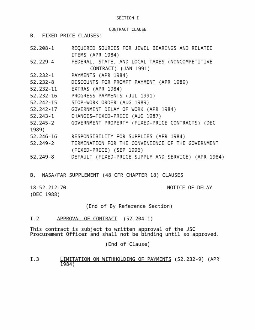
JSC DATA REQUIREMENTS DESCRIPTION (DRD)(Based on JSC-STD-123)
Type how many missions the design is certified for
Type the flight number for the first flight of the hardware.
List the limited life document or all items which do not meet the 10 years/100 missions design life.
List the hardware weight.
Type the dimensions and units (inches or cm) of the hardware.
Type the FMEA document number or indicate worksheets or other for the data.
Type the SAR document number or indicate if an HAW or other data is attached. The last page of the SMACAR may be used to substitute for a SAR.
Criticality Rationale Summary:Type the rationale for the criticality listed above.
Does test hardware configuration differ from flight hardware configuration? (Yes or No and indicate difference if no)
Installation Information:
Mounted:
Locker Stowed:
Stowed Other:
Launch Location:
Crew Cabin:
Payload Bay:
Space Lab/Hab:
Other:
Landing Location: Same or list otherOperational Location:
Crew Cabin:
Payload Bay:
Space Lab/Hab:
Other:
Choose the correct category to indicate how the hardware is installed, the launch, landing, and operational location. More than one category may be used for systems that are located in more than one location.
General Operational Information:Type the operational description of the hardware, crew interaction, activation, mission use, etc. This information is a detailed management summary of the hardware and operations that the certification covers.
Operational Performance Requirements:Type the operational performance requirements that are verified. These should be found in the Program requirements document or other specifications.
Crew Procedures Data Book:
Type the flight data file number where crew procedures are located.
Flight Rules (List all by FR# and Title): Type the flight rules by flight rule number and title. Ideally, this section will be the entire rule, pasted from the flight rules document located on the JSCDA8 file server.
Materials: JSC Materials Certification Memorandum:(Signature Required if no Memo #)
MATL - MUA Numbers:
Materials compatible:
IVA:
EVA:
Other
(Continue on a blank page if necessary)JSC Form 2341 (Rev Dec 91) MS Word (Aug 95)
J-1-232

JSC DATA REQUIREMENTS DESCRIPTION (DRD)(Based on JSC-STD-123)
:Type the material approval memo (ex. MATL-95-105) and any MUA’s for the hardware. Also, indicate the environment the material is approved for.If there is no approval memo, a signature from the JSC Materials Manager is required.
Electrical Interfaces: N/A if not applicable.(List all power and signal interfaces to the Orbiter or other equipment, including battery size and type if applicable).Power Interface Location:(D&C Panel #)
Type the Orbiter panel number for the switches, outlets, and circuit protection.
Orbiter Circuit Protection:
Type the rating of the fuse or breaker to protect the Orbiter wiring.
Hardware Nominal Amps:
Type the nominal operating current for the hardware.
Bonding Verification:
Type the documented test number or procedure which verifies Electrical bonding.
Hardware Circuit Protection:
Type the hardware circuit protection such as built in fuses or breakers.
Batteries: Type the quantity of cells, type of cells (D-cell), chemistry, voltage of battery pack,
Other: Type other pertinent electrical interface information not described in the other data fields.
Electromagnetic Compatibility Information: N/A if not applicable.EMC/EMI TEST
Type in the test document number that performed the EMC test.
24V to 32VDC Power Performance Test
Type in the test document number that performed the Voltage swing test and verified the hardware was operational at the required limits.
Temperature Validation: N/A if not applicable.QTT Range: Type the temperature
rangeQTT Test: Type in the test document
number that performed the test.
Cycles:
Type the number of cycles
QTVT Range:
Type the temperature range
QTVT Test: Type in the test document number that performed the test.
Cycles:
Type the number of cycles
Non-operating Temperature Limits:
Type the survivable temperature limits for the hardware when not activated.
Operating Temperature Limits: Type the survivable temperature limits for the hardware when activated.
Survivable Mission Operational Time Limit:
Type the worst case mission time limit for operation of the hardware based on temperature limits.
Touch Temperature Test: Type in the test document number that performed the test.
Acceptance Thermal: N/A if not applicable.ATT Range: Type the temperature
rangeATT Test: Type in the test document
number that performed the Cycles:
Type the number of cycles
(Continue on a blank page if necessary)JSC Form 2341 (Rev Dec 91) MS Word (Aug 95)
J-1-233

JSC DATA REQUIREMENTS DESCRIPTION (DRD)(Based on JSC-STD-123)
test.QATT Range:
Type the temperature range
QATT Test: Type in the test document number that performed the test.
Cycles:
Type the number of cycles
ATVT Range:
Type the temperature range
ATVT Test:TPS
Type in the test document number that performed the test.
Cycles:
Type the number of cycles
QATVT Range:
Type the temperature range
QATVT Test:
Type in the test document number that performed the test.
Cycles:
Type the number of cycles
Structural Validation: N/A if not applicable.Factor of Safety for Test: Type the required Factor of Safety Factor of Safety for Analysis: Type the required Factor of SafetyStructural Integrity Verification Plan: Type Document # Stress Analysis: Type Document # Fracture Control Summary Report: Type Document # Fracture Plan: Type Document #QVT Amplitude:
Type the spectrum information for the X,Y, & Z axis vibration spectrum.
QVT Test: Type in the test document number that performed the test.
Duration:
20G Crash Test:
Type in the test document number that performed the test.
Shock Test: Type in the test document number that performed the test.
Limit Loads: Type the “certified to” load limits information pertinent to the use of the hardware.
Limit Loads Test:
Type in the test document number that performed the test.
Life Cycles: Type the “certified to” life cycle limits. Life Cycle Testing:
Type in the test document number that performed the test.
Captive Fastener Cycle Life:
Indicate any cycle life limited items, such as captive fasteners, and how many cycles are acceptable.
Fastener Life Tracability Per:
Indicate how the installation/removal of limited cycle items, such as fasteners, are tracked.
Pressure Systems:
N/A if not applicable.System Operational Pressure Range
Acceptance Vibration: N/A if not applicable.AVT Amplitude: .04 g2/Hz (+ X,Y,Z) Type in
the acceleration amplitude if different from the normal AVT levels.
AVT Test: Type in the test document number that performed the test.
Duration:
Type the duration of the vibration test per axis. (ex. 1 min/axis)
QAVT Amplitude:
.067 g2/Hz (+ X,Y,Z) Type in the acceleration amplitude if different from the normal QAVT levels.
QAVT Test:
Type in the test document number that performed the test.
Duration:
Type the duration of the vibration test per axis. (ex. 1 min/axis)
Acoustics/Noise:
N/A if not applicable.
O/A dB Level Type the O/A level determined by Acoustics Type in the test document number
(Continue on a blank page if necessary)JSC Form 2341 (Rev Dec 91) MS Word (Aug 95)
J-1-234

JSC DATA REQUIREMENTS DESCRIPTION (DRD)(Based on JSC-STD-123)
the acoustic test. TestTPS that performed the test.
Performance Verification: N/A if not applicable.AcceptancePre-flight Testing Functional Checkout Procedure, ATP, or other/OMI/OMRSD
Interface Verification Test: IVT/SAIL/OMRSD/CEIT/etc.
Type in the test document number that performed the acceptance test.
Type in the test document number that performed the interface verification test.
Pre-flight Functional Checkout Procedure PIA/OMI/OMRSD/etc.
Other Functional performance testing
Type in the test document number that performed the pre-flight verification test.
Type in the test document number that performed the test.
Waivers or Requirements Deviations: N/A if not applicable.Requirement Waived:
Type requirement that was waived.
CR# Type in the Change Request number which documents the waiver approval.
If this certification is NOT for 100 Missions:Give the reason here for the limitation and indicate which flights the hardware is approved for.If the hardware is certified for one or more missions, but less than 100, indicate if the design is limited or each serial number is limited, and list the flights that the hardware is approved for. An example is if the hardware is certified for 1 mission, indicate if the design is limited to one specific mission or if each serial number is limited to one flight. (An item may be certified for one mission based on specific mission environmental or operational information and has only been tested or analyzed for that specific mission. This type of certification is a mission specific certification and the certification will be revoked after that mission. An item may be certified for one mission based on other factors such as qualification testing which only encompassed one missions worst case exposure. This type of certification is not mission specific and any serial number may be flown for one mission. This would be a limited life item that can be tracked.
If no SAR or HAW, list potential hazards, controls, and verificationMaterials Flammability, Toxicity,
Offgassing Verified Controlled per Materials memo.
Mechanical Impact/Structural Failure Verified Controlled per Stress Analysis and testing listed.Physiological Sharp Edges/Corners/Pinch
PointsVerified Radius requirement from ( JSC 17481) listed on drawings
Physiological Acoustical Noise Verified controlled per acoustic test aboveElectrical EMI/EMC Verified Controlled per test data listedPhysiological Hot/Cold Surfaces Verified Controlled per test data listed
Contamination Verified Controlled per Materials memo and Electrical Discharge/Shock Verified Controlled perExplosion Verified Controlled per
OtherOtherOther
A SAR is required for all hardware. The Safety Section above is only used when a SAR has not been provided as a separate document. The information contained in the SMACAR should provide verification of most hazard controls. If there is no SAR or HAW or other Safety analysis
(Continue on a blank page if necessary)JSC Form 2341 (Rev Dec 91) MS Word (Aug 95)
J-1-235

JSC DATA REQUIREMENTS DESCRIPTION (DRD)(Based on JSC-STD-123)
documentation submitted, the SMACAR can serve as the documentation but all information must be provided. Examples of the generic hazards to explore are indicated in the table above. List other hazards as appropriate and provide the verification of the controls.
(Continue on a blank page if necessary)JSC Form 2341 (Rev Dec 91) MS Word (Aug 95)
J-1-236

JSC DATA REQUIREMENTS DESCRIPTION (DRD)(Based on JSC-STD-123)
Acronyms
ATP - Acceptance Test ProcedureATT - Acceptance Thermal Test (See JSC-SP-T-0023)AVT - Acceptance Vibration Test (See JSC-SP-T-0023)CEIT - Crew Equipment Interface TestD&C - Display and ControlEMC - Electromagnetic Compatibility (See JSC-SL-E-0001 and SL-E-0002)EMI - Electromagnetic Interference (See JSC-SL-E-0001 and SL-E-0002)EVA - Extravehicular activityICD - Interface Control DocumentIVA - Intravehicular activityIVT - Interface Verification TestMUA - Materials usage agreement.OMRSD - Operations Maintenance Requirements Specification DocumentPDA - Pre Delivery AcceptancePIA - Pre Installation Acceptance QATT - Qualification Acceptance Thermal Test (See JSC-SP-T-0023)QAVT - Qualification Acceptance Vibration Test (See JSC-SP-T-0023)QTT - Qualification Thermal Test (See JSC-SP-T-0023)QTVT - Qualification Thermal Vacuum Test (See JSC-SP-T-0023)QVT - Qualification Vibration Test (See JSC-SP-T-0023)TPS - Test preperation sheet
(Continue on a blank page if necessary)JSC Form 2341 (Rev Dec 91) MS Word (Aug 95)
J-1-237

JSC DATA REQUIREMENTS DESCRIPTION (DRD)(Based on JSC-STD-123)
1 DRD Title RESERVED 2. Current Version Date
3. DRL Line
RFP/Contract No.
This plan shall include, but not be limited, the following:
1. DRD Title 2. Current Version Date
3. DRL Line
RFP/Contract No.
DEVELOPMENT AND DESIGN TEST PROCEDURES / REPORT
1/27/97 17 9-BL3-08-7-03P
4. Use (Define need for, intended use of, and/or anticipated results of data)These detailed procedures are to be followed in the performance of tests and reporting to be conducted in accordance with specification requirements to assure verification of design of the end item.
5. DRD Category: (check one) Technical Administrative SR&QA6. References (Optional) 7. Interrelationships (e.g., with other DRDs) (Optional)
8. Preparation Information (Include complete instructions for document preparation)
1. The contractor shall prepare and submit Design Verification Test (DVT) Procedures for each component, assembly, system, etc., to be tested as required by contract. The procedures shall provide detailed documentation of all testing required to demonstrate that the item is in compliance with all applicable specification requirements.
2. The procedure, in a format acceptable to the procuring activity, shall contain a list of tests, sequence of tests, conditions to be established for each test, instrumentation requirements, detailed procedures to be followed in conducting each test, data recording requirements, values and tolerances required, provisions for recording and evaluating non-conformances, data sheets for recording values to be obtained, and time duration of each test.
3. The procedure shall, in addition, including the following:
a. Assure the attainment of repeatable conditions both standard and simulated.
b. Establish and determine significant failure modes.
c. Determine the effects of varied stress levels and performance parameters.
d. Determine the affects of combinations of tolerances and drift of design parameters.
4. The contractor shall prepare and submit to NASA test reports covering the applicable testing program, in accordance with the following:
a. Except as otherwise specified on the applicable Data Requirements List (DRL), test
(Continue on a blank page if necessary)JSC Form 2341 (Rev Dec 91) MS Word (Aug 95)
J-1-238

JSC DATA REQUIREMENTS DESCRIPTION (DRD)(Based on JSC-STD-123)
reports shall be prepared in accordance with a standard format.
b. The report shall include complete descriptions of each test conducted. These descriptions shall cover the test objective, test procedure, test result, and discussion and significant events pertaining to the test.
c. The report shall include drawings, graphs, tables, photographs, etc., as necessary to show or support the test or equipment. These may also be provided to show or establish before-and-after conditions, results, requirements, etc.
When the test procedures are not included in the body of the report, the report shall include, as an appendix, the complete approved test procedure, and data sheets.
(Continue on a blank page if necessary)JSC Form 2341 (Rev Dec 91) MS Word (Aug 95)
J-1-239

JSC DATA REQUIREMENTS DESCRIPTION (DRD)(Based on JSC-STD-123)
1. DRD Title 2. Current Version Date
3. DRL Line
RFP/Contract No.
Problem Reporting and Corrective Action (PRACA)
29 Mar 96 18 9-BL3-08-7-03P
4. Use (Define need for, intended use of, and/or anticipated results of data)To report problems (as defined below) and describe their resolutions.
5. DRD Category: (check one) Technical Administrative SR&QA6. References (Optional) 7. Interrelationships (e.g., with other DRDs) (Optional)JSC 246368. Preparation Information (Include complete instructions for document preparation)
Reference Documents:a. JSC 24636, “JSC Orbiter and Government Furnished Equipment (GFE) Problem
Reporting and Corrective Action (PRACA) Requirements”
SCOPE:
PRACA reportable problems are defined as functional failures, overstress or potential overstress of hardware, unsatisfactory conditions, and unexplained anomalies which occur on flight products, flight-like products, or ground support equipment (GSE) during qualification testing and during or subsequent to acceptance testing. GSE reporting is limited to GSE problems which could result in injury, loss of personnel capability, or loss of vehicle systems.
CONTENTS:
A. Initial notification/report shall occur within 24 hours after isolation to the Line Replaceable Unit/Orbital Replacement Unit level or lower and shall include the following data:
1. A uniquely identifiable report number;2. The date the problem occurred if known, if unknown the date it was detected;3. The location at the time of occurrence/detection;4. The test or operation (code)* being performed at time of occurrence;5. The prevalent conditions (code)* at time of occurrence;6. The non-conforming product identification:
a. part name;b. part number;c. serial number, logistical control number, lot number, or version number (if
applicable);d. manufacturer.
7. Contractor end item model number;8. Brief narrative description of nonconformance, including comparison of expected events with actual events (or results);9. A brief title;10. Technical point of contact name;11. Technical point of contact phone number
(Continue on a blank page if necessary)JSC Form 2341 (Rev Dec 91) MS Word (Aug 95)
J-1-240

JSC DATA REQUIREMENTS DESCRIPTION (DRD)(Based on JSC-STD-123)
B. Additional preliminary data shall be delivered within 5 working days after the initial notification. Data shall include any additions/modifications to previous submittal plus:
1. Vehicle effectivity2. Subsystem(s) affected (if known);3 Next higher assembly (as applicable) identification:
a. part number;b. part name;c. serial number, logistical control number, or version number;d. manufacturer.
4. Time/cycles in use (if applicable);5. FMEA number (if applicable);6. Non-conforming product manufacturer’s CAGE code;7. Planned date of resolution;
C. The final resolution (close-out) shall include the following additional data:1. Resolution narrative which includes
a. Corrective action that has been established including reference to released documentation establishing this corrective action, or
b. When not establishing corrective action to preclude recurrence of the problem provide a narrative explanation which documents the rationale. This narrative shall also include the following:(1.) Effects on mission, if nonconformance recurred, and recommended
operational work around procedures;(2.) Methods of detecting the problem inflight/on-orbit. Indicate how the crew
will be made aware of the problem or what automatic system detects or corrects the problem;
(3.) When last test of product, prior to mission, is performed;(4.) Assurance that explanations using redundancy and/or alternate modes of
operation as one of the elements do not negate each other;2. Criticality or severity of the nonconformance with relationship to mission effects;3. All end items and/or missions that may be affected by the problem;4. Previous history of non-conforming product;5. Problem report numbers related to the same problem;6. Cause (code)* which indicates what action caused the failure;7. Defect (code)* which indicates what defect caused the failure;8. Material (code)* which indicates the material that failed;9. Recurrence control (code)* which indicates what action was taken as a result of the
nonconformance;10. Indication as to whether or not the problem will cause a revision to a CIL;11. Related document identification (waiver number, CCB directive, etc.);12. Date of resolution.
*Codes are per SSP 30524, D.1-3.1, Table F Type Element Code Translations
FORMAT:
(Continue on a blank page if necessary)JSC Form 2341 (Rev Dec 91) MS Word (Aug 95)
J-1-241

JSC DATA REQUIREMENTS DESCRIPTION (DRD)(Based on JSC-STD-123)
All problems common to the Shuttle Program GFE and Station Program GFE are entered initially into the ISS PRACA system. The ISS PRACA system can be accessed via the World Wide Web. To access PRACA reports or to submit failure reports use the PRACA on the WEB home page using the following address:http://issa-www.jsc.nasa.gov/ss/issapt/praca_on_the_web.html
If a message comes back "Forbidden" then apply for Space Station Team Page Bulletin Board access using the following URL address:
http://issa-www.jsc.nasa.gov/ss/admin/ro.html
MAINTENANCE: Update as required.
(Continue on a blank page if necessary)JSC Form 2341 (Rev Dec 91) MS Word (Aug 95)
J-1-242

JSC DATA REQUIREMENTS DESCRIPTION (DRD)(Based on JSC-STD-123)
1. DRD Title 2. Current Version Date
3. DRL Line
RFP/Contract No.
LIMITED-LIFE ITEM LIST 29 Mar 96 19 9-BL3-08-7-03P
4. Use (Define need for, intended use of, and/or anticipated results of data)Identify and control limited-life items.
5. DRD Category: (check one) Technical Administrative SR&QA6. References (Optional) 7. Interrelationships (e.g., with other DRDs) (Optional)below.8. Preparation Information (Include complete instructions for document preparation)
Reference Documents:a. NHB 5300.4, 1D-2, "Safety, Reliability, Maintainability, and Quality Provisions for the
Space Shuttle Program"b. JSC 17057, “GFE Limited Cycle Time/Age Life Items Requirements”
1. SCOPE: Identify time/cycle-sensitive components and age-controlled items and related requirements for inspection, maintenance, and replacement of these items. Limited-life items include limited-shelf life, limited-operating life, time-action control sensitive items, or a combination of these. Maintain time/cycle historical log evaluation of accrued time to determine remaining life.
2. FORMAT: Electronic tables for entry into NASA databases.
3. CONTENT: a. Items shall be identified by part name and number, life limit, life limiting parameter, or part/material; its function; any limitations on number of refurbishments; and any data related to operational use, test, handling, or inspection.
b. Requirements for maintenance of historical equipment data and records to verify that time/cycle- and age-sensitive items are controlled within acceptable limits. Entries to the equipment data records shall be complete and self-explanatory, and shall include, but not be limited to, the following:
Part Data:
Shuttle & Station: Part Name Part Number Serial number Date of manufacture Time (age) limit/cycle limit
Part instance limited-life data: Next higher assembly part number Part instance location code Part instance Logistics Control Number (LCN)
(Continue on a blank page if necessary)JSC Form 2341 (Rev Dec 91) MS Word (Aug 95)
J-1-243

JSC DATA REQUIREMENTS DESCRIPTION (DRD)(Based on JSC-STD-123)
Life-limit cycles Life-limit mean time between failures Mean time between failure units (e.g., hrs.) Beginning of life-limit accrual criteria Part instance "birthday"
Serialized Part Life Accrual Data: Next higher assembly part number Part instance location code Part instance Logistics Control Number (LCN) Accrued cycles Accrued In-service Time Date/Time of last accumulation Projected cycles remaining Projected life remaining Absolute life end date
c. The status reports shall include the accrued time and cycles for each item by part and/or serial number, location, and remaining life.
d. Waiver reports are required to document instances where an item has exceeded its time/cycle limit and rationale for accepting an item for flight or in support of flight. The waiver shall include item name, number, serial number, time or cycle limit, reason the item has (or will) exceed its time/cycle limit, and contractor rationale for accepting the item for flight or proposed action.
e. The Limited-Life Items List data requirements applies to all flight hardware. For Station, Limited-Life Items List data must be accessible in the Vehicle Master Database (VMDB) 145 days prior to the IDR that covers the first flight deployment of the hardware.
4. MAINTENANCE: Update as required. Multiple deliveries of the GFE do not require corresponding data deliveries.
(Continue on a blank page if necessary)JSC Form 2341 (Rev Dec 91) MS Word (Aug 95)
J-1-244

JSC DATA REQUIREMENTS DESCRIPTION (DRD)(Based on JSC-STD-123)
1. DRD Title 2. Current Version Date
3. DRL Line
RFP/Contract No.
MASTER AUTHORIZED CHANGE RECORD (MACR)
1/27/97 20 9-BL3-08-7-03P-
4. Use (Define need for, intended use of, and/or anticipated results of data)To provide a historical record of authorized Class I and Class III changes for interchangeable end items/components within one EMU hardware number
5. DRD Category: (check one) Technical Administrative SR&QA6. References (Optional) 7. Interrelationships (e.g., with other DRDs) (Optional)CSD-SH-021, REV A8. Preparation Information (Include complete instructions for document preparation)
1. A Master Authorized Change Record (MACR) shall be prepared for all deliverable contract end items or separable components having its own change tracking requirement within one EMU hardware number. The MACR shall be prepared for each serialized group of end items/components which are fully interchangeable as described in CSD-SH-021, as contractually applicable.
2. Class I and Class III changes shall be entered on the MACR when:
The change has been contractually authorized by issuance of a Contract Change Order (CCO) or Supplemental Agreement (SA) and:
a. When a change previously submitted as Class I has been approved as a Class II change and is for record purposes only; or
b. The authorization creates a new end item/component under the requirement of 1 above and a new MACR is prepared; or
c. The authorization is not effective to the total serialized end items of one EMU hardware number family, and a new MACR is prepared for the unique, non-interchangeable serialized group; or
d. The authorization changes the quantity of end items/components; or
e. The authorization requires a Class I or Class III change to engineering drawings; or
f. The change is effective to the Specification/Assembly Drawing (S/AD) but requires tracking for end item accomplishment; i.e., a change to a numerical value of the S/AD (torque, pressure, relief, etc.) for which the end item/component must be retested or adjusted; or
g. When a record of physical interface fit/function must be performed and recorded as completed.
3. The MACR shall provide the information as shown on the attached MACR form.
(Continue on a blank page if necessary)JSC Form 2341 (Rev Dec 91) MS Word (Aug 95)
J-1-245
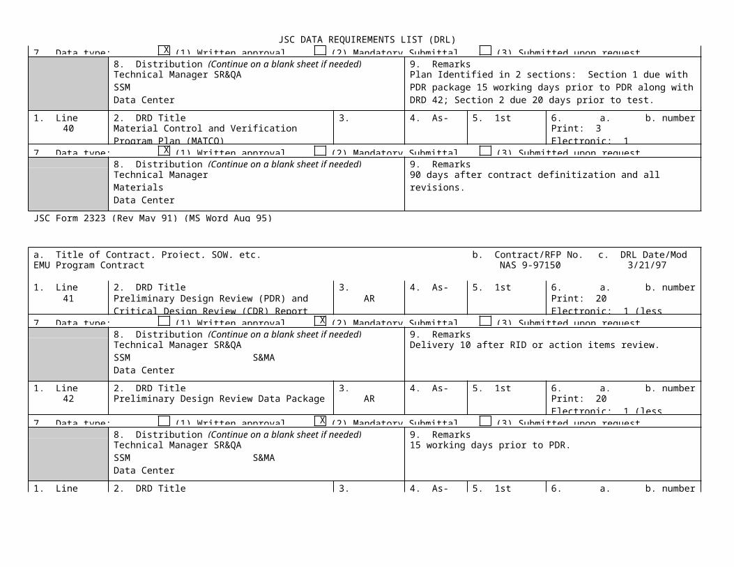
JSC DATA REQUIREMENTS DESCRIPTION (DRD)(Based on JSC-STD-123)
4. The MACR shall be provided by the responsible preparer to the organization responsible for maintenance of the end item/component ADP (Acceptance Data Package) or manufacturing record (when an ADP is not authorized) for updating of the end item/component ACR (Authorized Change Record).
5. The MACR shall be completed as follows:
a. Enter the end item name from the drawing.
b. Enter the serialized block of end items for this MACR effectivity.
c. Enter the approval authority of the MACR contractor’s Configuration Manager.
d. Enter page number and total pages.
e. Date of this issue.
f. This letter revision.
g. Superseded revision and date.
h. Contractual authorization for this line end item (contractors only).
i. The authorizing CCBD (JSC Configuration Change Board Decision) number.
j. The contractor’s responding or initiated ECP (Engineering Change Proposal).
k. The contractor’s or JSC document which releases the engineering change in total to all authorized end items of this MACR.
l. The dash number configuration created by incorporation of this Class I change. For a Class III change, enter the Top Assembly Drawing revision letter.
m. Short descriptive change title.
n. Enter pertinent remarks, i.e., “ECO13456 must be incorporated prior to incorporation of this change,” and number each note related to the line end item.
(Continue on a blank page if necessary)JSC Form 2341 (Rev Dec 91) MS Word (Aug 95)
J-1-246
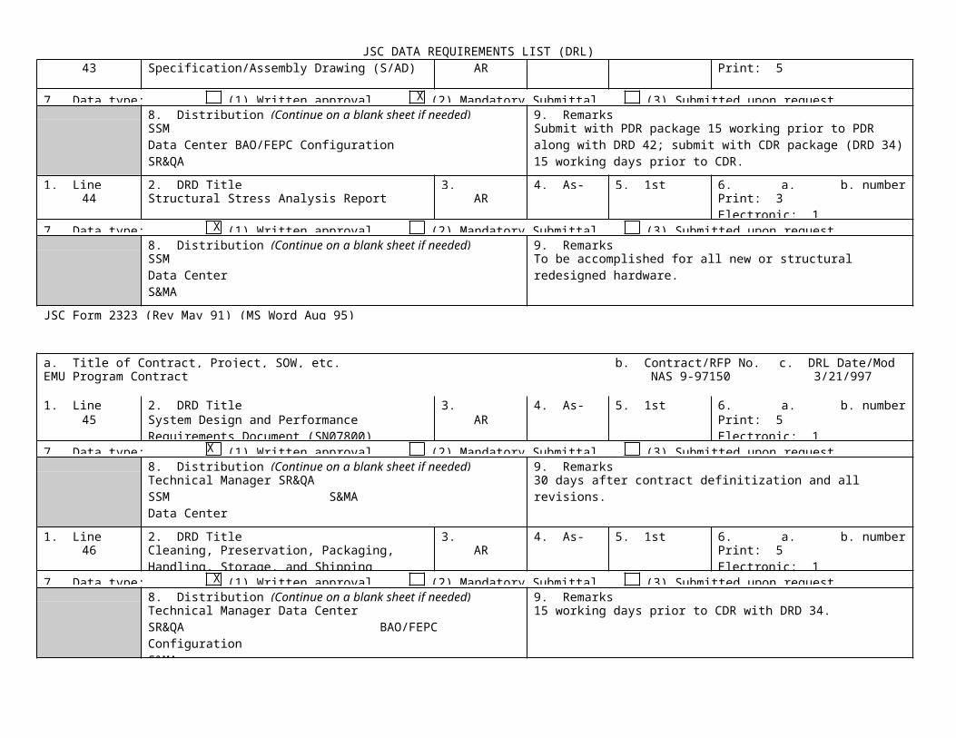
JSC DATA REQUIREMENTS DESCRIPTION (DRD)(Based on JSC-STD-123)
1. DRD Title 2. Current Version Date
3. DRL Line
RFP/Contract No.
PREDELIVERY ACCEPTANCE TEST PROCEDURE (PDA)
1/27/97 21 9-BL3-08-703P
4. Use (Define need for, intended use of, and/or anticipated results of data)To ensure that the end item conforms to the requirements of the applicable end item specification / assembly drawing.5. DRD Category: (check one) Technical Administrative SR&QA6. References (Optional) 7. Interrelationships (e.g., with other DRDs) (Optional)JSCM-5312, ISO 9001 NFSD Part 18-52.245 and Alternate #18. Preparation Information (Include complete instructions for document preparation)
1 This Data Requirement Description (DRD) establishes the requirements for the preparation of a procedure covering the test and inspection of EMU hardware to ensure compliance with specification/assembly drawing requirements prior to delivery.
2 The contractor shall prepare and submit to NASA a detailed test procedure for each contractually identified end item and its related support equipment. The procedures shall outline the contractual test program concepts, providing the methods for implementing the level(s) and type(s) of test requirements applicable to a specific end item and its related support equipment.
3 The end item test procedures shall include the detailed description of contractor testing and checkout of the end item utilizing its related support equipment from post manufacturing checkout through checkout prior to shipment to the NASA site. Specifically, the end item test procedures shall provide the following detailed information:
a. Test program mission objectives and related test philosophy, including various test relationships.
b. Measuring and test equipment to be used specifying range, accuracy, and type (specify the particular scale, dial, or device to be observed; if recording type, indicate details of tape, film, or sensitized paper).
c. EMU hardware and related support equipment configuration.
d. Support equipment requirements and configuration, including part number, serial number, nomenclature, drawing number, etc.
e. Identification of all applicable detailed operating procedures, process specifications, program description documents, test and inspection procedures, etc., including document number, revision, and title, and operational checks or preliminary calibration of test setup.
f. Exact method of inspecting or measuring, including necessary manipulation of
(Continue on a blank page if necessary)JSC Form 2341 (Rev Dec 91) MS Word (Aug 95)
J-1-247

JSC DATA REQUIREMENTS DESCRIPTION (DRD)(Based on JSC-STD-123)
controls on the article involved and on the measuring and test equipment.
g. Conditions that must be maintained during inspection and test, including ambient or environmental conditions, and precautions to be observed to prevent damage to the articles or instruments involved.
h. Criteria for passing or failing test, or for determining conformance or rejection of the article, including reference to workmanship inspection standards.
i. Details for sampling plans to be used, if applicable.
4 References to other contractor documentation is permissible, providing the references are adequate and include such identification elements as title, number, applicable revision, etc. When a document to be referenced would only be applicable to a minor or limited extent, the contractor shall make every effort to include the applicable requirement(s) and avoid direct reference. All referenced documentation shall be readily available to the procuring activity upon request.
(Continue on a blank page if necessary)JSC Form 2341 (Rev Dec 91) MS Word (Aug 95)
J-1-248

1. DRD Title 2. Current Version Date
3. DRL Line
RFP/Contract No.
HAZARDOUS WASTE QUANTITY REPORT
1/27/97 22 9-BL3-08-7-03P
4. Use (Define need for, intended use of, and/or anticipated results of data)To be used for hazardous waste management to help comply with regulations, executive orders and NASA goals by reports and forecasts of hazardous waste quantities
5. DRD Category: (check one) Technical Administrative SR&QA6. References (Optional) 7. Interrelationships (e.g., with other DRDs) (Optional)
SOW 4.5.18. Preparation Information (Include complete instructions for document preparation)
1. SCOPE: The report shall cover the total waste management in all areas of the program.
2. CONTENT : The Hazardous Waste Quantity Report shall provide:
a. Hazardous waste quantities that were transferred to the Government for disposal. The contractor shall make special note of unused materials due to expired shelf life or incorrect procurement.
b. Forecast of hazardous waste materials that will be transferred to the Government for the next quarter.
3. FORMAT: Contractor format is acceptable with NASA approval.
4. MAINTENANCE: Changes shall be incorporated as required by change page or complete reissue.

JSC DATA REQUIREMENTS DESCRIPTION (DRD)(Based on JSC-STD-123)
1. DRD Title 2. Current Version Date
3. DRL Line
RFP/Contract No.
NASA/GOVERNMENT INDUSTRY DATA EXCHANGE PROGRAM (GIDEP) ALERT SYSTEM DOCUMENTATION
1/27/97 23 9-BL3-08-7-03P
4. Use (Define need for, intended use of, and/or anticipated results of data)NASA/GIDEP distributed ALERTS identify hardware problems noted on other programs or projects and provide instructions for contractor investigation and response on usage on the Space Shuttle and International Space Station Programs with recommendations/corrective action information.
5. DRD Category: (check one) Technical Administrative SR&QA6. References (Optional) 7. Interrelationships (e.g., with other DRDs) (Optional)
6.18. Preparation Information (Include complete instructions for document preparation)
Documentation is to provide a controlled method for ALERT initiation, investigation, and response. The contractor shall be notified whenever an ALERT-reported part is identified within the EEE parts list submitted.
The contractor shall respond by summary status on the alert response form (attachment) to all NASA/GIDEP ALERT’s. Where use is identified investigate, resolve, and document parts and materials problem(s) dispositions by letter. Previously published ALERT’s shall be included in the investigation to assure that lots, batches, or groupings of hardware noted as suspected in the ALERT are not used.
When the contractor encounters a significant problem with a part or material which may adversely affect the equipment, the contractor shall initiate an ALERT and submits it to the NASA/JSC ALERT coordinator.
The contractor prepared ALERTS shall be submitted to NASA/JSC for formal approval and release on Department of Defense form DD-1938.
The ALERT system notifies all organizations of problems associated with flight hardware of GSE item which could cause loss of GSE, vehicle, or personnel.
(Continue on a blank page if necessary)JSC Form 2341 (Rev Dec 91) MS Word (Aug 95)
J-1-250

JSC DATA REQUIREMENTS DESCRIPTION (DRD)(Based on JSC-STD-123)
1. DRD Title 2. Current Version Date
3. DRL Line
RFP/Contract No.
Space Shuttle GFE Safety Analysis Report (SAR) and Hazard Report (HR)
28 Nov 95 24 9-BL3-08-7-03P
4. Use (Define need for, intended use of, and/or anticipated results of data)The SAR is used to document the safety analysis performed on a system. The HR is used to provide program management the change in risk.
5. DRD Category: (check one) Technical Administrative SR&QA6. References (Optional) 7. Interrelationships (e.g., with other DRDs) (Optional)below. S&MA-1, SMACAR8. Preparation Information (Include complete instructions for document preparation)
Reference Documents:a. NHB 5300.4 (1D-2), “Safety, Reliability, Maintainability and Quality Provisions for the
Space Shuttle Program”b. NSTS 22254, “Methodology for Conduct of Space Shuttle Program Hazard Analyses"c. JSC 17481A, "Safety Requirements Document for JSC Space Shuttle Flight Equipment"d. NSTS 07700, vol. V, "Information Management"
1. SCOPE : A SAR and HR's are applicable to all Government-furnished equipment (GFE) classified flight hardware.
2. FORMAT: The format of the SAR and HR's shall be in accordance with NSTS 22254.
3. CONTENTS : The hardware provider shall provide the SAR and HR's for program management visibility.
a. SAR: A safety analysis shall be performed in accordance with NSTS 22254 and a SAR shall contain the following as a minimum:
(1) System, subsystem, assembly, or item identifier (2) Event and mission phases considered. (3) Page, date, and revision number. (4) Identification of the preparer and approvals with signatures. (5) Description of the type of hazard analysis performed.
(6) Analysis of each generic hazard listed in JSC 17481A and unique hazards showing applicability or
inapplicability, controls, and verifications. (7) Safety matrix relating equipment subsystems to generic hazards. (8) Hazard list providing HR number, title, status, and classification for any baselined hazards. (9) Summary of open HR's with actions required for closure. (10) Summary of candidate accepted risks with acceptance rationale.
(Continue on a blank page if necessary)JSC Form 2341 (Rev Dec 91) MS Word (Aug 95)
J-1-251

JSC DATA REQUIREMENTS DESCRIPTION (DRD)(Based on JSC-STD-123)
The SAR may be sufficed by a properly and completely filled out hazard analysis worksheet or S&MA Certification Approval Request (SMACAR) in situations where the system, subsystem, assembly, or item is non critical, low cost, and not complex in design.
b. HR's: If HR's are required based on the safety analysis performed, the HR's shall comply with the requirements of NSTS 07700, volume V and NSTS 22254. The HR's shall contain, by attachment, documentation of work performed to support closure.
(Continue on a blank page if necessary)JSC Form 2341 (Rev Dec 91) MS Word (Aug 95)
J-1-252

JSC DATA REQUIREMENTS DESCRIPTION (DRD)(Based on JSC-STD-123)
1. DRD Title 2. Current Version Date
3. DRL Line
RFP/Contract No.
ACCIDENT, INCIDENT, AND SAFETY ACTIVITIES REPORT
1/27/97 25 9-BL3-08-7-03P
4. Use (Define need for, intended use of, and/or anticipated results of data)
5. DRD Category: (check one) Technical Administrative SR&QA6. References (Optional) 7. Interrelationships (e.g., with other DRDs) (Optional)
8. Preparation Information (Include complete instructions for document preparation)
ACCIDENT / INCIDENT REPORTING
1. IMMEDIATE NOTIFICATION: The contractor shall report immediately (24 hours) by telephone to JSC Operations Safety Branch (Extension 5231 or 6208) all accidents, incidents, and/or exposure which result in:
a. All fatalities.
b. All serious (hospitalization required) lost-time occupational injury and/or illness to employees.
c. Property damage of $25,000 or more associated with his operations.
d. Near-miss incidents with a hazard potential of a serious or significant nature.
All fires shall be reported immediately by telephone to the JSC Fire Department (extension 3333).
2. MONTHLY REPORT: A monthly report of all accidents (including vehicle accidents), incidents, injuries, and fires shall be submitted to the JSC Operations Safety Branch. The enclosed form 288, titled "Accident/Incident Statistics", is representative of a format acceptable to, and contains the minimum information to be transmitted to the Operations Safety Branch. Negative reports, which include hours worked, are required monthly. A description of safety activities that have been accomplished during the past month should be described. Each major section of the safety plan should be discussed, with significant accomplishments highlighted. Follow-up actions and following months planned activities should be included in the final paragraph of the report.
3. QUARTERLY REPORT: Send a NASA Form 345, Accident Cause Analysis Report, on a quarterly basis to the JSC Operations Safety Branch.
4. SAFETY ASSESSMENT REPORT: An annual written self-evaluation and assessment report shall be submitted during first quarter of the new year to the JSC Operations Safety Branch. The report shall include:
(Continue on a blank page if necessary)JSC Form 2341 (Rev Dec 91) MS Word (Aug 95)
J-1-253

JSC DATA REQUIREMENTS DESCRIPTION (DRD)(Based on JSC-STD-123)
a. The internal assessment of safety program effectiveness indicating areas of strength, weakness, goals, and objectives for the following report period.
b. Safety concerns and resolutions relating to JSC operations which may have been identified during the report period.
c. Unresolved safety concerns relating to JSC operations which the contractor feels merit attention of the JSC Operations Safety Branch.
(Continue on a blank page if necessary)JSC Form 2341 (Rev Dec 91) MS Word (Aug 95)
J-1-254

JSC DATA REQUIREMENTS DESCRIPTION (DRD)(Based on JSC-STD-123)
1. DRD Title 2. Current Version Date
3. DRL Line
RFP/Contract No.
PRESSURE VESSEL HISTORICAL DATA
1/27/97 26 9-BL3-08070-3P
4. Use (Define need for, intended use of, and/or anticipated results of data)To provide information demonstrating that acceptance requirements have been satisfied for deliverable pressure vessels.
5. DRD Category: (check one) Technical Administrative SR&QA6. References (Optional) 7. Interrelationships (e.g., with other DRDs) (Optional)
8. Preparation Information (Include complete instructions for document preparation)
1. SCOPE
The documentation shall be provided for flight or flight-type pressure vessels and pressure vessels installed in associated ground support equipment (GSE) which interfaces with flight hardware.
2. CONTENTS
a. First Article Pressure Vessel Data: The following documentation shall be provided indicating hardware effectivity:
(1) Manufacturing sequence of operations.
(2) Manufacturing and process specifications (includes chemical processes, cleaning, welding, heat treatment, etc.).
(3) Detail and assembly drawings, inspection methods and/or specifications.
(4) Fluid-to-fluid and fluid-to-materials compatibility.
(5) Design and qualification data.
b. Per Unit Pressure Vessel Data: The following documentation shall be provided for flight vehicle pressure vessels (with only Item (10) below applicable to GSE pressure vessels):
(1) Material composition and mechanical properties.
(2) Mechanical properties of forging and vessel.
(3) Heat treatment of forging and vessel.
(4) Fluid exposure and temperature during fabrication and testing.
(Continue on a blank page if necessary)JSC Form 2341 (Rev Dec 91) MS Word (Aug 95)
J-1-255

JSC DATA REQUIREMENTS DESCRIPTION (DRD)(Based on JSC-STD-123)
(5) Cleaning materials used, sequence of use, pressure, if applicable.
(6) Welding, weld joint preparation, cover and backup gases and controls, repair procedures and controls, filler wire composition.
(7) Inspection results.
(8) Discrepancy and MR records. (9) Pressurization Data Log delineating actual chronological tests and checkout
history, including all proof, leak, and cycling data along with the magnitude of pressure, type of pressurant, and number of pressure cycles to which the vessel was subjected.
(10) All GSE pressure vessels which have been designed, fabricated, and tested to the requirements of the ASME Code for Unfired Pressure Vessels, Section VIII, will have a certification of compliance to design, fabrication, and testing in accordance with the ASME Code.
3. FORMAT
Documentation shall be provided in contractor or subcontractor format.
4. MAINTENANCE
To be maintained by page revision/total reissuance, as applicable to the individual information element.
(Continue on a blank page if necessary)JSC Form 2341 (Rev Dec 91) MS Word (Aug 95)
J-1-256
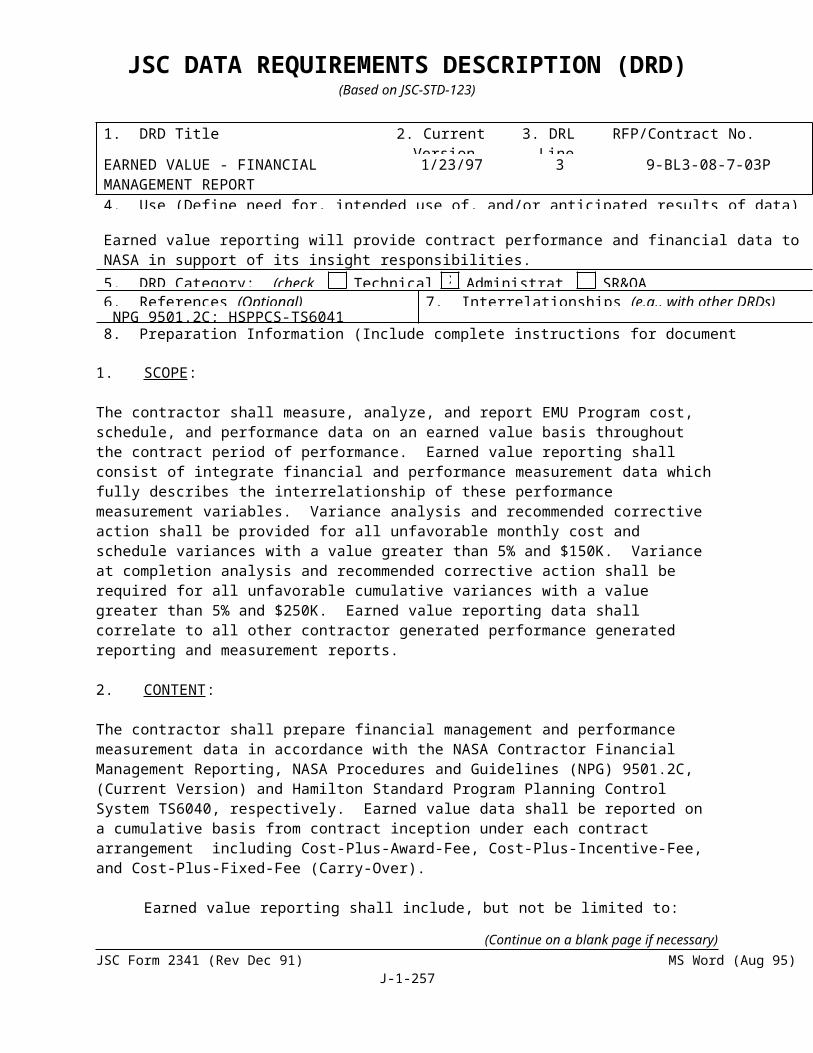
JSC DATA REQUIREMENTS DESCRIPTION (DRD)(Based on JSC-STD-123)
1. DRD Title 2. Current Version Date
3. DRL Line
RFP/Contract No.
PRESSURE VESSEL/SYSTEM RECERTIFICATION
1/27/97 27 9-BL3-08-7-03P
4. Use (Define need for, intended use of, and/or anticipated results of data)Data required to demonstrate implementation of NMI 1710.3 using the guidelines of NHB1700.6, to ensure that all ground-based pressure vessels and pressurized systems are certified safe to operate and are recertified periodically. 5. DRD Category: (check one) Technical Administrative SR&QA6. References (Optional) 7. Interrelationships (e.g., with other DRDs) (Optional)
8. Preparation Information (Include complete instructions for document preparation)
1. Scope - The Pressure Vessel/System Recertification covers all ground-based pressure vessels and pressurized systems under the contractor’s responsibility.
2. Applicable Documents - NMI 1710.3 Safety Program for Pressure Vessels and Pressurized SystemsNHB 1700.6 Guide for in-service Inspection of Ground-Based Pressure Vessels and Systems
3. Contents - In accordance with guidelines in NHB 1700.6.
4. Format - Contractor format is acceptable.
5. Maintenance - Changes shall be incorporated by change page or complete reissue.
(Continue on a blank page if necessary)JSC Form 2341 (Rev Dec 91) MS Word (Aug 95)
J-1-257

JSC DATA REQUIREMENTS DESCRIPTION (DRD)(Based on JSC-STD-123)
1. DRD Title 2. Current Version Date
3. DRL Line
RFP/Contract No.
Space Shuttle GFE Failure Modes and Effects Analysis (FMEA) and Critical Items List (CIL)[FMEA1]
28 Nov 95 28 9-BL3-08-7-03P
4. Use (Define need for, intended use of, and/or anticipated results of data)To identify to program management the risk associated with design, use, and failure of systems.5. DRD Category: (check one) Technical Administrative SR&QA6. References (Optional) 7. Interrelationships (e.g., with other DRDs) (Optional)below.8. Preparation Information (Include complete instructions for document preparation)
Reference Documents:
a. NHB 5300.4 (1D-2), “Safety, Reliability, Maintainability and Quality Provisions for the Space Shuttle Program”
b. NSTS 22206, “Instructions for Preparation of Failure Modes and Effects Analysis FMEA) and Critical Items List (CIL)
SCOPE: The FMEA and CIL are applicable to all Government-furnished equipment classified as flight hardware.
FORMAT: Electronic delivery or through data keyed directly into the NASA application. (JSC will identify the available application.) The format of the FMEA and CIL shall be in accordance with NSTS 22206. A suggested format is provided, with the numbers in parentheses corresponding to the data elements in NSTS 22206, table 3.0 for FMEAs and table 4.0 for CILs. Other formats are acceptable provided all FMEA data elements are included.
CONTENTS: The hardware provider shall provide FMEAs and CILs for project and program management.
An FMEA shall be performed on every system, subsystem, assembly, or item to identify failure modes and the effects thereof for support of additional design action, safety analysis, hardware/software interface analysis, test planning, mission planning, preparation of mandatory inspection points, fault detection and isolation, maintainability analysis and planning, maintenance planning, and logistics planning.
The FMEA shall be conducted and prepared in accordance with NSTS 22206. The FMEA may be sufficed by a properly completed criticality worksheet alone if the system, subsystem, assembly, or item under analysis is noncritical.
The CIL is used to identify critical items which require special risk assessments to support the activities supported by the FMEA and waivers to program requirements. The CIL shall be conducted and prepared in accordance with NSTS 22206.
(Continue on a blank page if necessary)JSC Form 2341 (Rev Dec 91) MS Word (Aug 95)
J-1-258

JSC DATA REQUIREMENTS DESCRIPTION (DRD)(Based on JSC-STD-123)
FAILURE MODE EFFECTS ANALYSIS/CRITICAL ITEMS LIST
FMEA NUMBER: ORIGINATOR PROJECT:PART NAME: LRUPART NUMBER: QUANTITY: PART NUMBER: LRU/ORU PART NAME: SYSTEM:LSC CONTROL NO: DRAWING/REF DESIGNATOR:
SUBSYSTEM:ZONE/LOCATION: EFFECTIVITY/AFFECT STAGE:
CRITICALITY:CRITICAL ITEM?
CRITICALITY CATEGORY____
REDUNDANCY SCREEN:
ORBITER/SPACE STATION
A -B - C -D.-
FUNCTION:
FAILURE MODE CODE:FAILURE MODE:
CAUSE:.
FAILURE DETECTION:REMAINING PATHS: EFFECT/ MISSION PHASE:
___________________________________________________________________________________________________________CORRECTIVE ACTION:
-FAILURE EFFECTS-
END ITEM/LRU/ORU/ASSEMBLY:
SUBSYSTEM/NEXT ASSEMBLY/INTERFACE:(Continue on a blank page if necessary)
JSC Form 2341 (Rev Dec 91) MS Word (Aug 95)J-1-259

JSC DATA REQUIREMENTS DESCRIPTION (DRD)(Based on JSC-STD-123)
SYSTEM/END ITEM/MISSION:
CREW/VEHICLE :
FAILURE MODE EFFECTS ANALYSIS/CRITICAL ITEMS LIST
FMEA NUMBER: ORIGINATOR PROJECT:PART NAME: LRUPART NUMBER: QUANTITY: PART NUMBER: LRU/ORU PART NAME: SYSTEM:LSC CONTROL NO: DRAWING/REF DESIGNATOR:
SUBSYSTEM:ZONE/LOCATION: EFFECTIVITY/AFFECT STAGE:
HAZARD INFORMATION: HAZARD: YES___ NO__
HAZARD ORGANIZATION CODE:
HAZARD NUMBER:TIME TO EFFECT:TIME TO DETECT:TIME TO CORRECT:FAILURE DETECTION/FLIGHT:
REMARKS:
-RATIONALE FOR ACCEPTABILITY-
(A) DESIGN:
(B) TEST:
(C) INSPECTION:
(D) FAILURE HISTORY:
(E) OPERATIONAL USE:
(F) MAINTAINABILITY:
PREPARED BY: REVISION:
DATE: WAIVER NUMBER
(Continue on a blank page if necessary)JSC Form 2341 (Rev Dec 91) MS Word (Aug 95)
J-1-260

JSC DATA REQUIREMENTS DESCRIPTION (DRD)(Based on JSC-STD-123)
1. DRD Title 2. Current Version Date
3. DRL Line
RFP/Contract No.
Reliability and Maintainability (R&M) Plan 14 Mar 96 29 9-BL3-08-7-03P
4. Use (Define need for, intended use of, and/or anticipated results of data)Used to assure proper implementation of R&M quantitative requirements. Used by program management to verify predictions, allocations, etc., are consistent with program requirements.
5. DRD Category: (check one) Technical Administrative SR&QA6. References (Optional) 7. Interrelationships (e.g., with other DRDs) (Optional)NHB 5300.4 (1A-1), NHB 5300.4 (1E), NHB 8. Preparation Information (Include complete instructions for document preparation)
Scope: Formulate an R&M Plan to serve as a master planning, program definition, and control document to govern the R&M quantitative-related activities required for the project.
Format: Each quantitative requirement shall be addressed in narrative form and in sufficient detail to describe the philosophy and approach for implementation. Existing policies and procedures can be used if in total compliance with the requirements stated below.
Contents: The plan shall identify and define the following as a minimum:
a) The work to be accomplished for each applicable task.
b) The time phasing and staff loading involved.
c) The organizational element assigned responsibility and authority for implementing the required task.
d) Lines of communication between the organizational element responsible for implementing the task and other interfacing organizational elements.
e) Appropriate NASA-contractor program milestone review points.
f) Method of control over subcontractor and vendor-related tasks.
g) The purpose and expected results of each task. Planned methods for monitoring, assessing, reporting, and taking appropriate action regarding status, accomplishments, and problems.
h) Specific techniques for allocating quantitative requirements to lower level functional elements of the system, subsystem, assembly, or components.
i) Specific techniques for making R&M predictions.
j) The method of data collection and analysis, and plan for ensuring an effective corrective action system.
(Continue on a blank page if necessary)JSC Form 2341 (Rev Dec 91) MS Word (Aug 95)
J-1-261

JSC DATA REQUIREMENTS DESCRIPTION (DRD)(Based on JSC-STD-123)
k) Data base requirements.
l) Contents and submittal schedules of the prediction, allocation, assessment, and verification reports.
m) Means by which demonstration and verification will be accomplished.
(Continue on a blank page if necessary)JSC Form 2341 (Rev Dec 91) MS Word (Aug 95)
J-1-262

JSC DATA REQUIREMENTS DESCRIPTION (DRD)(Based on JSC-STD-123)
SEE SA 285 FOR CHANGES TO THIS DRD1. DRD Title 2. Current
Version Date3. DRL
Line RFP/Contract No.
EEE PART DATA REQUIREMENTS 1/27/97 30 9-BL3-08-7-03P
4. Use (Define need for, intended use of, and/or anticipated results of data)Define documentation requirements for controlling and qualifying EEE Parts.
5. DRD Category: (check one) Technical Administrative SR&QA6. References (Optional) 7. Interrelationships (e.g., with other DRDs) (Optional)NHB 5300.4 (1D-2)8. Preparation Information (Include complete instructions for document preparation)
I. EEE PART SPECIFICATION
The specification shall completely describe performance, design, qualification, and quality assurance requirements for EEE parts specified in the end item design. EEE parts in the end item shall be purchased to a controlling specification. (Not required where existing JAN-TX and MIL-ER or other existing specifications satisfy NHB 5300.4 (1D-2) for this type documentation.)
The drawings/specifications shall delineate, as a minimum:
1. A complete identification of the part including generic equivalent, physical, environmental, and performance requirements; quality and reliability assurance requirements including inspections and tests for qualification, acceptance, and lot sampling where required; explicit requirements to be satisfied in accepting parts for use in the contract hardware including 100 percent screen and burn-in; packaging, storage, and handling requirements; traceability requirements; and data retention and submittal requirements.
2. Where a combination of specifications is used collectively to provide all the above requirements for a single part type, the detail specification (slash sheet, specification or source control drawing, etc.) for that part type shall provide detailed cross-reference to all other applicable specifications.
3. Each EEE parts drawing/specification shall be identified by a unique number and shall be subject to a formal system of change control.
4. Seller-originated requirements documents which are incorporated into the part specification by reference shall be submitted along with the part specification in order to facilitate review of the total requirements.
II. EEE PART QUALIFICATION TEST
The document will cover each new EEE part qualified by test to its specification. The test reports shall contain:
1. Reference to related qualification test plan/description of test.
(Continue on a blank page if necessary)JSC Form 2341 (Rev Dec 91) MS Word (Aug 95)
J-1-263

JSC DATA REQUIREMENTS DESCRIPTION (DRD)(Based on JSC-STD-123)
2. Sample size, measurements taken, test procedure, sequence, equipment used and acceptance criteria.
3. Identification of measurements outside acceptable criteria, identification of all failures, failure analysis.
4. Statement as to successfulness of test, and qualification status of the part.
5. Reference to the controlling specification to which the qualification is applicable.
III. EEE PART QUALIFICATION TEST PLAN/ REQUEST
The EEE Part Qualification Test Request/Plan serves as the vehicle for coordinating approval for expenditure of funds to qualify a part. The request for part qualification shall include the following.
1. Part identification and manufacturer.
2. Application (black box).
3. Tests required.
4. Tests not required on the basis of existing data.
5. Schedule impact.
6. Part specification.
The Parts Qualification Test Plan shall as a minimum describe the following:
1. Completed Parts Procurement Drawing/Specification for each part covered by the plan as a separate document.
2. Detail description of the test. Where appropriate, refer to MIL-STRD-202, etc., for test methods used. Where appropriate, identify the facility or agency that will do the test, the equipment to be used, and whether the agency is certified by NASA or the buyer.
3. Show a detailed schedule of events and show how part qualification meets end item schedules.
IV. EEE PART APPLICATION AND STRESS ANALYSIS
These data are to verify appropriate departing and stress conditions of EEE parts in design applications
These data shall document the results of EEE parts application and stress analysis reviews as follows:
(Continue on a blank page if necessary)JSC Form 2341 (Rev Dec 91) MS Word (Aug 95)
J-1-264

JSC DATA REQUIREMENTS DESCRIPTION (DRD)(Based on JSC-STD-123)
1. Determination of electrical upper thermal stresses experienced by parts in their equipment applications and verifications of compliance with derating requirements.
2. Consideration of functional adequacy and possible sensitivity of parts to specific applications.
V. EEE PART LISTS
1. The EEE parts list identifies EEE parts used in flight equipment and other contractor, subcontractor, and supplier equipment design applications. This list should be submitted a minimum of 3 times (PDR, CDR, and at hardware delivery) and should include as a minimum the requested data at the time of each submission.
2. The following information is to be submitted at PDR and amended as necessary during other requested submissions:
a. Identification of parts by generic part name, type, and common designator (e.g., diode, zener, 1N2970).
b. Specification control drawing numbers.
c. Manufacturer's name and production location. QPL parts also require the manufacturer's name.
d. Quantity used per application.
e. Component (black box) part number.
3. The information below with the exception of lot date code is to be submitted at CDR and again with any amendments at hardware delivery. The lot date code documenting the actual parts used in the hardware will be submitted at the time of hardware delivery.
a. Manufacturer's full part number or complete military part specification if the device is on the QPL.
b. Qualitication status. This is qualification at the part level, not the equipment level, and can be obtained by one of the following methods:
(1) Successful qualification testing of the part type to be used (parts listed in MIL-STD-975 or other MIL-SPEC parts procured from qualified product list sources meet this requirement).
(2) Documented similarity to a part that has been qualified by test. The similar part must include documents showing it was manufactured by the same supplier, on the same line, with the same processes and technology as the qualified part.
(3) Successful prior usage in a program with similar or higher reliability
(Continue on a blank page if necessary)JSC Form 2341 (Rev Dec 91) MS Word (Aug 95)
J-1-265

JSC DATA REQUIREMENTS DESCRIPTION (DRD)(Based on JSC-STD-123)
requirements. Available information should include program name, quantity used, estimate of part hours, and documented failure history.
c. IPAR/NSPAR number for irregular parts.
d. Any additional lot date code data on specific parts used is to be provided when available.
4. The following information on the LRU number and each specific serial number used shall be recorded and submitted as the as-built record upon hardware delivery:
a. Reference designator.b. Part number.c. Manufacturer's code.d. Lot date code/serial number for the specific part installed.
VI. REQUEST APPROVAL FOR IRREGULAR EEE PARTS USAGE AND WTSC (WET TANTALUM SLUG CAPACITOR) APPLICATION(S)
DEFINITION
Irregular parts: A part which is deficient in or lacking one or more of the following controls:1. Specification2. Qualification test to the specification3. Traceability4. Screen and burn-in
CONTENTS
1. Irregular parts usage request shall, as a minimum, contain the following information:
a. Equipment name, function and criticality, component number and serial number, supplier/subcontractor and effectivity.
b. Subassembly name, number, and criticality.
c. Part name, type and common designator (closest commercial equivalent), specification part and part manufacturer or parts contained in the as-designed equipment.
d. Irregular part number, part manufacturer and specification number, part name, part type, common designation (closest commercial equivalent).
e. Salient differences including SCD reliability and quality requirements and screening and burn-in between design baseline and irregular parts.
f. Qualification status and basis of qualification of irregular part.
(Continue on a blank page if necessary)JSC Form 2341 (Rev Dec 91) MS Word (Aug 95)
J-1-266

JSC DATA REQUIREMENTS DESCRIPTION (DRD)(Based on JSC-STD-123)
g. Limited life (yes, no).
h. Justification for use of the irregular part including technical adequacy.
Where a limited life item is affected, the contractor shall ensure that proper changes are made to limited life control lists.
2. The request to use WTSC parts shall as a minimum contain the following information:
a. Complete identification of proposed part.
b. The intended application of the part. For WTSC's a circuit diagram, and circuit analysis is required to demonstrate absence of adverse conditions on the WTSC such as reverse bias, ripple current, etc.
c. Part manufacturer(s).
d. Other type capacitors which could be used in lieu of the WTSC.
e. Justification for requiring the part.
f. Part specification.
g. Qualification status and schedule impact if qualification test is required.
FORMAT: Letter with enclosures as appropriate.
(Continue on a blank page if necessary)JSC Form 2341 (Rev Dec 91) MS Word (Aug 95)
J-1-267

JSC DATA REQUIREMENTS DESCRIPTION (DRD)(Based on JSC-STD-123)
1. DRD Title 2. Current Version Date
3. DRL Line
RFP/Contract No.
QUALITY PROGRAM PLAN 1/27/97 31 9-BL3-08-7-03P
4. Use (Define need for, intended use of, and/or anticipated results of data)To describe how the contractor will ensure compliance with cited quality requirements defining the total quality program from the initial phase throughout the development, fabrication, and delivery of articles of required quality.5. DRD Category: (check one) Technical Administrative SR&QA6. References (Optional) 7. Interrelationships (e.g., with other DRDs) (Optional)
8. Preparation Information (Include complete instructions for document preparation)
1. SITE PLANS - Separate quality program plans, or plan having separate parts, shall be prepared for the contractor's activities at the plant site and at each remote site.
2. QUALITY PROGRAM PLAN CONTENTS
a. Charts and narrative statements describing each element of the contractor's organization (e.g., procurement, engineering, reliability, fabrication, test, safety and quality assurance) which implement the quality program and detailed statements of duties, functions, and responsibilities relating to each quality program task. The plan shall show the relationship of the individual managing the quality program with each element performing quality program tasks, including his authority to control and monitor cited tasks.
b. Narrative descriptions which describe the contractor's execution and management of each task. These shall be detailed in terms of when, by which organizations, and by which methods each task will be accomplished. Applicable contractor policies and procedures shall be referenced in the plan.
c. Identification of those elements of the planned program which will utilize the contractor's existing quality program documents and operations and identification of those requiring change. Proposed changes needed to meet cited requirements and the time schedule for implementing such changes shall be delineated.
d. Manufacturing flow charts indicating the flow of fabrication and assembly operations and related inspection and test points will be maintained at the contractor's facility available for customer representative review.
3.0 QUALITY PROGRAM PLAN FORMAT
The plan shall, as a minimum, encompass the following format with attendant discussions of:
a. Quality Program Management
1. Flow charts depicting the contractor's proposed operations(Continue on a blank page if necessary)
JSC Form 2341 (Rev Dec 91) MS Word (Aug 95)J-1-268

JSC DATA REQUIREMENTS DESCRIPTION (DRD)(Based on JSC-STD-123)
2. Contractor's organizational and functional charts3. Quality status reporting4. Relationship with the reliability program5. Quality documentation change control6. Quality training program
b. Design and Development Control
1. Establishment, identification, review, change control, and effectivity of technical documents such as specifications, procedures, drawings, fabrication and planning documents, and process sheets defining characteristics and design criteria necessary for procurement, fabrication (including assembly) and inspection and test operations.
2. Quality support to design review.
c. Identification and Data Retrieval
1. Identification control method for ensuring assignment of unique part, serial, and lot numbers in a consecutive manner.
2. Identification list development to ensure that records and the related articles may be readily located and retrieval in the event that verification of, or removal of
articles or materials becomes necessary.
d. Procurement Controls
1. Selection of contractor procurement sources.
2. Procurement document review and control; control of supplier quality programs, including how basic technical and detailed quality requirements will be
delineated to suppliers.
3. Contractor quality assurance personnel at source, if applicable.
4. Methods for coordinating with Government personnel for which the Government agency elects Government source inspection.
5. Receiving inspection system including receiving records, supplier rating systems, post-award surveys of supplier operations, coordination of contractor/supplier inspections and tests, and nonconformance information feedback.
e. Fabrication Controls
1. Fabrication operations controls.2. Article and materials controls.3. Cleanliness controls and procedures; contamination controls, as applicable.
(Continue on a blank page if necessary)JSC Form 2341 (Rev Dec 91) MS Word (Aug 95)
J-1-269

JSC DATA REQUIREMENTS DESCRIPTION (DRD)(Based on JSC-STD-123)
4. Process controls and procedures.5. Workmanship standards.
f. Inspection and Tests
1. Inspection and test planning2. Test specifications3. Inspection and test procedures (These procedures shall insure that Government
qualityrepresentatives are notified 48 hours in advance of the time articles or materials
are planned for inspection or test).
4. End item inspection and test specifications, procedures, and controls5. Inspection and test performance controls6. Qualification test article controls, requalification, qualification based on similarity,
procedures, and controls7. End item inspection and test reports; end item reinspection and retest8. Inspection and test records and data9. Contractor quality assurance verification actions prior to, during, and
subsequent to testing10. Nondestructive evaluation (NDE)11. Quality program audits
g. Nonconforming Article and Material Control
1. Nonconforming documentation2. Remedial and preventive action3. Initial review dispositions4. Material review board5. Requests for NASA contracting officer approval6. Supplier material review boards
h. Metrology Controls
1. Acceptance and evaluation2. Article or material measurement processes3. Calibration measurement processes4. Traceability to NBS5. Handling, storage, and transportation6. Identification and labeling7. Establishment of calibration intervals8. Recall system9. Calibration records
10. Environmental requirements11. Remedial and preventive action
i. Inspection status stamp control
(Continue on a blank page if necessary)JSC Form 2341 (Rev Dec 91) MS Word (Aug 95)
J-1-270

JSC DATA REQUIREMENTS DESCRIPTION (DRD)(Based on JSC-STD-123)
j. Handling, storage, preservation, marking, labeling, packaging, packing, shipping, and documentation package
k. Sampling plans, statistical planning and analysis
l. Government property control
(Continue on a blank page if necessary)JSC Form 2341 (Rev Dec 91) MS Word (Aug 95)
J-1-271
JSC DATA REQUIREMENTS DESCRIPTION (DRD)(Based on JSC-STD-123)
1. DRD Title 2. Current Version Date
3. DRL Line
RFP/Contract No.
ACCEPTANCE DATA PACKAGE (ADP) 1/27/97 32 9-BL3-08-7-03P
4. Use (Define need for, intended use of, and/or anticipated results of data)The Acceptance Data Package (ADP) will provide complete documentation at the time of acceptance of the EMU hardware end item.
5. DRD Category: (check one) Technical Administrative SR&QA6. References (Optional) 7. Interrelationships (e.g., with other DRDs) (Optional)See Block 8.8. Preparation Information (Include complete instructions for document preparation)
REFERENCE:
SN-S-008 Software Data Package Requirements SpecificationSN-D-007 Acceptance Package RequirementsISO 9001
ADP shall be prepared in accordance with the referenced documents as appropriate.
PURPOSE
The purpose of this instruction is to establish the minimum requirements for the ADP delivered with each procured end item, in order that a chronological history of the equipment configuration and quality status will be available at all times.
SCOPE
This instruction provides guidance in establishing ADP requirements for spaceflight and equipment. ADP will be delivered with each functional end item.
GENERAL REQUIREMENTS
A. A DD 250/1149 (or other Government recognized “shipper” document, such as JSC Form 290), with quality control validation, will be required for all shipments. The shipper document will indicate nomenclature, part number, serial number, and quantity of hardware shipped. Shipping documents will identify any end item shortages, and reference all the applicable waivers. The shipper will list the ADP as being part of the shipment.
B. A chronological log of the equipment’s configuration and quality status; along with the DD 250/1149, is the minimum acceptance data that will accompany any shipment of functional hardware. A JSC Form 772, Functional Equipment Historical Record, or equivalent, will be used for this purpose. HS Tag SSS0006 will be used for all nonfunctional Hardware or when JSC Form 772 is not required for functional hardware. This tag will contain, as a minimum, the following information:
1. Acceptable (for its intended use)(Continue on a blank page if necessary)
JSC Form 2341 (Rev Dec 91) MS Word (Aug 95)J-1-272

JSC DATA REQUIREMENTS DESCRIPTION (DRD)(Based on JSC-STD-123)
2. Identification by part number and serial number3. Indication of Government acceptance4. Cleanliness certification5. Proof pressure loading certification (if applicable)6. Material certification (if applicable)
SPECIFIC REQUIREMENTS FOR FUNCTIONAL ITEMS
Each ADP will have, as a minimum, the following sections with data as applicable:
A. Index or Table of Contents
An index or inventory of the ADP contents, along with the brief description of each section. A negative statement at the beginning of a section is required if no entry is applicable. For example, if one of the following data requirements does not apply to a particular shipment, the section should be so noted.
B. Component/Equipment Historical Logs
During the acceptance testing and inspection, a log (JSC Form 772 Functional Equipment Historical Record, or equivalent) will be maintained to continuously document the history of the item or component. Each log will be chronologically maintained and will account for all periods of time, including idle time and movements of the item. Entries will be complete and self-explanatory and will reference the test and test results, configuration changes, special inspections, etc. The local Government Quality Assurance Representative will validate all entries.
C. Inventory of Serialized Components
A list of “field replaceable” serialized components will be included in the ADP. The list will contain the following:
1. Definitions - With respect to the succeeding paragraphs, the following definitions should be used:
a. End Item - An assemblage of nameplated, serialized components which has an acceptance data package meeting the requirements of the contract and which is shipped on a DD Form 250 to NASA/JSC. Spare parts and expendable components are not considered as end items for the purposes of this DRD.
b. Configuration - The end item as defined by a list of identified, part numbered, and serialized components.
c. Replacement - The process of component changeout, starting with removal of a named, part numbered, and serialized component. This may be followed by the replacement of either a different component after repair or refurbishment, for example. Replacement, as defined for purposes of this DRD, would not include changeout of expendable items such as batteries, lithium hydroxide cartridges, or other normally expended items. Replacement, as referred to in this DRD, would be appropriate for such situations as component failures, updating, or scheduled maintenance.
(Continue on a blank page if necessary)JSC Form 2341 (Rev Dec 91) MS Word (Aug 95)
J-1-273

JSC DATA REQUIREMENTS DESCRIPTION (DRD)(Based on JSC-STD-123)
d. Component - A subassembly of the end item which bears a nameplate, part number, and serial number. Screws, washers, shims, lengths of tubing, and housings are examples of items not included as components for the purposes of this DRD.
e. Authority - The identifying title and number of the working document which is used to effect the actual replacement operation. Examples of such paperwork are engineering work orders, test preparation sheets, discrepancy records, and material review board actions.
2. Configuration Record - A form shall be originated which carries a title block at the top of the page which contains the following information:
a. A descriptive title containing the words “configuration record.”
b. Words to the effect that NASA/JSC is the end item recipient.
c. Contract number.
d. The name of the end item.
e. The end item drawing number
f. Serial number of the end item.
Named columns shall be provided within which the following information may be recorded: Component names, part numbers and serial numbers, and a series of boxed spaces (no less than six) horizontally across from each numbered, serialized component listing. The column overseeing the boxes shall be entitled with words to the effect that this is the replacement column and that the replacement records should be consulted. As originally filled out, then the configuration record will have entries for all components with appropriate part numbers and serial numbers listed but with no entries in the boxes of the replacement column. As components are replaced, sequential entries are made in the boxes each time any of the components are removed and replaced. The sequential numbering is not in any way related to the order of the components or to the number of replacements for any one component. The first replacement would be noted with a “1” in the first box of that component. Replacement of another component midway down the page, for example, would result in a “2” being placed in the first box for this latter component. A repeat replacement of the first component would result in a “3” being placed in the second box for that component, and so on.
3. Replacement Record - The replacement record form shall have a title block containing the same information as the configuration record. The columns, however, should be so arranged as to give the following information (horizontally): replacement number (i.e., corresponding to the entries in the replacement section of the configuration record), part number of the “old” part, serial number of the “old” part, part number of the “new” part, serial number of the “new” part, site where replacement is made, place for QC stamp, date of replacement record columns would be blank. Referring back to the pervious example, the first component to be replaced would result in filling in of the first horizontal spaces in the columns of the replacement record. Replacement of the next failed component would occupy the second series of spaces, and repeat replacement of the first component would occupy the third series of spaces, and so on.
4. Miscellaneous - Use of the replacement record would commence during in-plant end item acceptance testing. Both the forms should be printed on paper suitable for reproduction (i.e., not a blue-line). Spaces for entry should be generous to allow for legible printing, as all entries will probably be made by hand in an ADP.
(Continue on a blank page if necessary)JSC Form 2341 (Rev Dec 91) MS Word (Aug 95)
J-1-274

JSC DATA REQUIREMENTS DESCRIPTION (DRD)(Based on JSC-STD-123)
D. Waivers/Deviations
A list of waivers/deviations will be provided, sequentially numbered or indexed, in order to determine the total number applicable to hardware. For Government-Furnished equipment, this information may be included in the JSC Form 772, System and Component Historical Record, or equivalent. Copies of the waivers/deviations will be included in the ADP.
E. Discrepancy Reports (DR’s)/Material Review Board (MRB) Actions
All MRB actions and open DR’s pertinent to EMU hardware or components being shipped will be provided in the same manner as E. above and included in the ADP.
F. Record Limited Life/Time and Cycle Requirements
A list of limited items will be included in the ADP and also a list of the critical time/cycle items, including the total time or cycles allowed and a record of the time or cycle used.
G. Nonflight or Temporary Installed Hardware
An itemized list of all nonflight or temporarily installed hardware will be provided. Such hardware will be suitably identified and logged to control the use and final removal. Serialized streamers will be attached to all nonflight items not requiring physical removal to complete flight installations except when the streamer might damage hardware.
H. Inspection and Test Procedures and Results
Identification of the final inspection and test procedures performed and a copy of the results thereto will be included in the ADP; i.e., predelivery acceptance (PDA), dimensional inspection, proof loading acceptance test or others, etc.
Acceptance test data sheets are included in acceptance test procedures as an attachment. One set of the acceptance test data sheets shall be filled out for each contract end item tested. The completed acceptance test data sheets for an end item shall become part of the acceptance data package of the part. Contractor to retain completed sheets for items using a Spacecraft Parts Tag (JSC Form 911) or equivalent.
The acceptance test data sheets shall include, but not be limited to, the following:
a) A heading with the document number, EMU hardware item nomenclature and providing space to record the date, part number, and serial number.
b) Reference the test procedure being accomplished along with acceptable values required.
c) Delineate each step of test inspection to be performed.
d) Columns for entries of initials or stamps, and dates, by the technician performing the step and by contractor quality representative and Government Quality Control (QC).
e) A column to record values experienced, and to indicate if the experienced values are accepted or rejected.
I. Certification of Compliance
The supplier will include in the ADP a certificate of compliance with the specifications and requirements of the contract.
(Continue on a blank page if necessary)JSC Form 2341 (Rev Dec 91) MS Word (Aug 95)
J-1-275

JSC DATA REQUIREMENTS DESCRIPTION (DRD)(Based on JSC-STD-123)
J. The following items are normally shipped as part of EMU hardware end items; however, if it is necessary to ship them separately, they will be accompanied by the data specified in the listings below:
PLSS Components
Item 111 SV778895 Primary Oxygen Bottle - Limited Life Data, Pressure Vessel Data
Item 120 SV785844 Dual Mode Relief Valve - Limited Life Data
Item 122 SV767798 CO2 Sensor - Limited Life Data, Calibration Data
Item 127 SV778543 Pump Inlet Filter - Limited Life Data
Item 131 SV769592 Primary Water Tank - Limited Life Data
Item 136 SV769512 Feedwater Pressure Regulator - Limited Life Data
Item 139 SV767796 Temperature Sensor - Limited Life Data or SV792503
Item 140 SV783850 Sublimator - Limited Life Data
Item 141 SV784943 Gas Trap - Limited Life Data
Item 145 SV785860 Relief Valve and Orifice - Limited Life Data
Item 146 SV787036 Positive Pressure Relief Valve - Limited Life Data
Item 147 SV767704 Negative Pressure Relief Valve - Limited Life Data or SV785927
Item 150 SV785970 Caution and Warning System - Limited Life Data
Item 112 SV778528 Primary Oxygen Pressure Sensor - Limited Life Data
Item 113 SV778873 Primary Pressure Control Module - Batch Control Data
Item 114 SV767788 Differential Pressure Sensor - Limited Life Data
Item 138 SV767793 Feedwater Pressure Sensor - Limited Life Data
SOP Components
Item 210 SV778880 Oxygen Bottle - Limited Life Data, Pressure Vessel Data
Item 213 SV778475 Secondary Oxygen Pressure Control Module - Limited Life Data, Batch Control Data
Item 215 SV778973 Pressure Transducer - Limited Life Data
DCM Components
Item 330 SV778872 Multiple Connector - Batch Control Data
Item 384 SV771987 Thermal Cover - Limited Life Data
(Continue on a blank page if necessary)JSC Form 2341 (Rev Dec 91) MS Word (Aug 95)
J-1-276

JSC DATA REQUIREMENTS DESCRIPTION (DRD)(Based on JSC-STD-123)
SCU Components
Item 410 SV778872 Multiple Connector - Batch Control Data
Item 420 SV778504 Oxygen Filter and Orifice - Batch Control Data
Item 424 SV784959 Potable Water Filter - Limited Life Data
Item 428 SV771749 SCU Sheath Assembly - Limited Life Data
EEH Components
SV76790 EEH Sheath Assembly - Limited Life Data
Battery Components
SV778526 Battery Relief Valve - Limited Life Data
The following components will require data packages containing the information noted:
Item 416 SV767709 Bacteria Cartridge
(a) Functional Equipment Historical Record (JSC Form 772)
(b) As-Built Parts list
(c) Data of Filter Medium Charging and Lot No.
(d) Shipping Paperwork
(e) Material Review Documentation
Item 350 SV792291 Electronic Assembly - Full Data Package
Item 385 SV779301 Oxygen, Water Manifold Assembly - Full Data Package
Item 123 SV787994 Fan/Separator/Pump Assembly
(a) Functional Equipment Historical Record (JSC Form 772)
(b) As-built Parts List
(c) Discrepancy Reports/MRB Actions
(d) Limited Life Information
(e) Test Procedures/Results
(f) Waiver Deviation Approval Request
Item 115 SV778540 Shear Plate Assembly
(a) Functional Equipment Historical Record (JSC Form 772)
(b) As-built Parts List
(Continue on a blank page if necessary)JSC Form 2341 (Rev Dec 91) MS Word (Aug 95)
J-1-277

JSC DATA REQUIREMENTS DESCRIPTION (DRD)(Based on JSC-STD-123)
(c) Discrepancy Reports/MRB Actions
(d) Limited Life Information
(e) Test Procedures/Results
(f) Batch Control Data
NOTE: These items are interchangeable items and, therefore, when shipped as part of the PLSS, an informational package for each will accompany the PLSS shipment.
(Continue on a blank page if necessary)JSC Form 2341 (Rev Dec 91) MS Word (Aug 95)
J-1-278

JSC DATA REQUIREMENTS DESCRIPTION (DRD)(Based on JSC-STD-123)
1 DRD Title 2. Current Version Date
3. DRL Line
RFP/Contract No.
AUTHORIZED CHANGE RECORD 1/27/97 33 9-BL3-08-7-03P
4. Use (Define need for, intended use of, and/or anticipated results of data)To provide a historical record of authorized changes and their incorporation into individual serialized end items or components.
5. DRD Category: (check one) Technical Administrative SR&QA6. References (Optional) 7. Interrelationships (e.g., with other DRDs) (Optional)
8. Preparation Information (Include complete instructions for document preparation)
1. An ACR (Authorized Change Record) shall be prepared and maintained for each deliverable contract end item or separable component.
2. Applicable changes to each end item/component shall be entered in the ACR in columns D through H from data presented on a MACR (Master Authorized Change Record) and will be a running lists of all Class I and Class III changes authorized for the particular individual serial number end item/component. Changes shall be entered on the ACR as MACR’s are received by the organization charged with maintenance of the end item/component ADP (Acceptance Data Package) or manufacturing records (when no AO ADP is required).
3. Changes incorporated into the end item/component shall be entered into columns I through L by the accomplishing organization with verification being entered in columns M and N by the applicable Quality Assurance/Inspection Agency.
4. The ACR shall be completed as follows:
a. End item/component nomenclature from drawing.b. End item/component serial number.c. Original issue date.d. Contract modification authorizing the change. e. JSC CCBD (Configuration Change Board Decision) number authorizing the contract
change.f. The number of the contractor initiated or responding ECP (Engineering Change
Proposal) describing the technical implementation of the changeg. The engineering release document number which incorporates the change into the
drawing for the total change incorporation.h. The new dash number generated by incorporation of this Class I change. For a
Class III change enter the top assembly drawing revision letter.i. The TPS (Test Preparation Sheet) (Ref. JSCM 5312) or contractor document
number which directs implementation of the authorized change into the end item/component.
j. The initials of the technician (or configuration manager) performing the work.k. The date of incorporation.
(Continue on a blank page if necessary)JSC Form 2341 (Rev Dec 91) MS Word (Aug 95)
J-1-279

JSC DATA REQUIREMENTS DESCRIPTION (DRD)(Based on JSC-STD-123)
l. The latest dash number created by incorporation of the Class I change. For a Class III change, enter the top assembly drawing revision letter which reflects that configuration.
NOTE
Items “i” through “n” are completed against the related line entry and shall indicatethe latest “AS BUILT” configuration. The latest configuration will always be minus (with open engineering changes) or equal to the “AS DESIGN” configuration. An example is the incorporation of the fourth of four changes authorized but not incorporated against a FACI baseline (-01), which, had all changes been incorporated sequentially would make the item a “-05.” In the case above, the item would become a “-05” configuration with the understanding that this configuration is minus or has three open engineering changes.
m. The inspector’s stamp who verifies the change was properly and completely incorporated.
n. The date of verification (if different than block k).
(Continue on a blank page if necessary)JSC Form 2341 (Rev Dec 91) MS Word (Aug 95)
J-1-280

JSC DATA REQUIREMENTS DESCRIPTION (DRD)(Based on JSC-STD-123)
1. DRD Title 2. Current Version Date
3. DRL Line
RFP/Contract No.
CRITICAL DESIGN REVIEW DATA PACKAGE
1/27/97 34 BL3-08-7-03P
4. Use (Define need for, intended use of, and/or anticipated results of data)To provide the documentation for review and analysis to establish a certification baseline of EMU hardware for a Critical Design Review.
5. DRD Category: (check one) Technical Administrative SR&QA6. References (Optional) 7. Interrelationships (e.g., with other DRDs) (Optional)CSD-SH-021 Rev A8. Preparation Information (Include complete instructions for document preparation)
1. SCOPE: The contractor shall prepare and submit a data package, including a complete documentation list, presenting the specification and drawing requirements necessary in establishing a certification baseline during the Critical Design Review (CDR).
2. CONTENT: The data package listing shall include, but not be limited to, the documentation indicated below. This documentation shall be approximately 90% complete or as otherwise indicated.
a. Logic diagrams or block diagrams of the system.b. Maintenance considerations.c. Data establishing compatibility with end item design criteria and end item functional
requirements.d. Schedule for equipment, fabrication, test readiness review, and testing.e. Handling and installation restrictions.f. Drawings and associated lists.g. Human factor considerations, including safety.h. Manufacturing considerations relative to unusual tooling or tolerance requirements.i. End item model specification (Part II) completed Specification/Assembly Drawing (S/AD).j. Acceptance test plan for EMU Hardware specification items.k. Reliability analysis, including math model if required.l. Summary of required state-of-the-art improvements.m. Test Plan for certification test for EMU Hardware specification items.n. Support data requirements and schedules for such items as instruction manuals,
maintenance manuals o. Contractor shall provide a list of all parts used in particular end items and their qualification
status in the following categories: Government and Industry Standard Parts, Vendor Parts, and Contractor Designed Parts. If a part has more than one identification number (contractor specification number and vendor part number), all numbers shall be listed and properly identified.
p. List of approved suppliers.q. Status of JSCM 8080 Standards Matrix as presented for compliance. Rationale and
waivers for noncompliance shall be a part of this package.
(Continue on a blank page if necessary)JSC Form 2341 (Rev Dec 91) MS Word (Aug 95)
J-1-281

JSC DATA REQUIREMENTS DESCRIPTION (DRD)(Based on JSC-STD-123)
3. FORMAT : The packages and listing shall be formulated by the top number precedence of the hardware downward to the last detailed item as contractually applicable.
(Continue on a blank page if necessary)JSC Form 2341 (Rev Dec 91) MS Word (Aug 95)
J-1-282

JSC DATA REQUIREMENTS DESCRIPTION (DRD)(Based on JSC-STD-123)
1. DRD Title 2. Current Version Date
3. DRL Line
RFP/Contract No.
MICROFILMING OF ENGINEERING DRAWINGS AND ASSOCIATED LISTS DOCUMENT
1/27/97 35 9-BL3-08-7-03P
4. Use (Define need for, intended use of, and/or anticipated results of data)To establish the procedure for the microfilming of engineering drawings and associated lists provided by a contractor
5. DRD Category: (check one) Technical Administrative SR&QA6. References (Optional) 7. Interrelationships (e.g., with other DRDs) (Optional)
8. Preparation Information (Include complete instructions for document preparation)
1. Prime Contractor Data : The contractor will provide a 35MM, Type I, Class I, silver halide first generation negative microfilm mounted in an aperture card for all engineering drawings, parts lists, specifications, and engineering changes in accordance with MIL-M-38761 and DOD-D1000B except as defined herein. A numerical index listing of all submitted aperture cards shall be provided. When more than one set of aperture cards is requested. Diazo type microfilm, Type II, Class 2, will be furnished for the quantities. Data shall be entered on NASA aperture cards by an automated keypunching system or manual typewriter in accordance with the following procedure:
a. Field One - Proprietary Designation (Column 1) - Do not use.
b. Field Two - Drawing Size (Column 2) - The drawing size designation letter as specified in standard MIL-STD-2 shall be used.
c. Field Three - Drawing Number (Columns 3-17) - Enter the documentation drawing number. When the drawing number is less than 15 digits, leave the columns to the right blank.
d. Field Four - Code Identification Number (Columns 18-22) - Enter the applicable manufacturer’s identification code number in accordance with federal handbook H4-1.
e. Field Five - Sheet Number (Columns 23-25) - Enter the documentation sheet number, right adjusted with zeros entered in the unused columns.
f. Field Six - Revision Letter (Columns 26-27) - Enter the documentation revision letter (or letter and number) of the sheet. When the revision is a single letter, it shall be entered in Column 27.
g. Field Seven - Number of Sheets (Columns 28-30) - Field seven is used only for the first sheet of documents. Enter the number of sheets of the document, right adjusted with zeros entered in the unused columns.
(Continue on a blank page if necessary)JSC Form 2341 (Rev Dec 91) MS Word (Aug 95)
J-1-283

JSC DATA REQUIREMENTS DESCRIPTION (DRD)(Based on JSC-STD-123)
h. Field Eight - Frame Number (Columns 31-32) - Enter the microfilm frame number. A single frame document shall have frame number “01” entered in this field. The last digit of the frame number of a multi-frame document (a drawing whose complete recording requires more than one frame of microfilm) shall be entered in column 32, right adjusted with zeros entered in the unused columns.
i. Field Nine - Number of Frames (Columns 33-34) - Enter the number of frames in this field. Entries shall be made for only the first frame of multi-frame document (a drawing whose complete recording required more than one frame of microfilm) shall be entered in Column 34, right adjusted with zeros entered in the unused columns.
j. Field Ten - Camera and Roll Number (Columns 35-40) - Do not use.
k. Field Eleven - Frame Sequence Number (Column 41-43) - Do not use.
l. Field Twelve - Project (Columns 44-45) - enter EMU project code number - OE.
m. Field Thirteen - Blank (Columns 46-47) - Do not use.
n. Field Fourteen - Control Activity (Columns 48-49) - Do not use.
o. Field Fifteen - Card Code (Columns 50-51) - Enter the letter A in Column 51. Do not use Column 50.
p. Field Sixteen - Security Classification (Column 52) - Enter the applicable security classification code letter as follows:
N - NoneC - ConfidentialM - Confidential - Modified handling authorizedS - SecretT - Top SecretE - Confidential - Restricted dataF - Secret - Restricted dataG - Top Secret - Restricted dataH - Confidential - Formerly restricted dataJ - Secret - Formerly restricted dataK - Top Secret - Formerly restricted data
q. Field Seventeen - Deck Code (Columns 78-80) - Do not use.
2. Vendor Data (All Tier Vendors) : The prime contractor shall provide in purchase order(s) or contract(s) to vendors a requirement for preparation of engineering data for all vendor item(s) in specified format, except when the vendor designs or develops an item, as a result of the prime contractor’s purchase order or contract, in which case drawings shall be prepared in vendor format.
(Continue on a blank page if necessary)JSC Form 2341 (Rev Dec 91) MS Word (Aug 95)
J-1-284
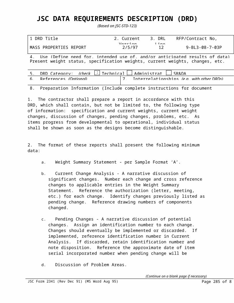
JSC DATA REQUIREMENTS DESCRIPTION (DRD)(Based on JSC-STD-123)
3. When standard commercial non-repairable items and hardware (such as hinges, locks, light bulbs, resistors, capacitors, tube sockets, hoses, nuts, bolts, and screws) not covered by Military Standards or Industrial Association Standards are used by the contractor exactly as procured from the supplier or manufacturer, Class I data need not be prepared for these parts provided they are described on the assembly drawing concisely with a commercial source. When the item is not described in accordance with this criteria, reference shall be made to the item, the supplier or manufacturer’s name, address, part number, and catalog number on the drawings, if the catalog defines the part in sufficient detail to enable the Government to identify and procure the item. If suitable catalog data is not available, or the manufacturer’s existent drawings does not comply with this requirement, a specification source control drawing shall be prepared for the item.
When the original drawings are to be furnished at the termination of the contract, or thirty (30) days prior to delivery of the last item unless otherwise stated on the NASA Form 2323, data Requirements List (DRL), none of the original drawings shall be folded, and they shall be shipped flat or rolled. They shall be shipped FOB (prime or vendor)/subcontractor) origin on U.S. Government Bills of Lading (GBL), commercial bills of lading, or when dimensions and cube size permit, by mailing indicia via U.S. Postal Service. Mailing indicia and U.S. GBL shall be obtained from the cognizant transportation officer. All modes of delivery are acceptable except regular railway freight.
(Continue on a blank page if necessary)JSC Form 2341 (Rev Dec 91) MS Word (Aug 95)
J-1-285
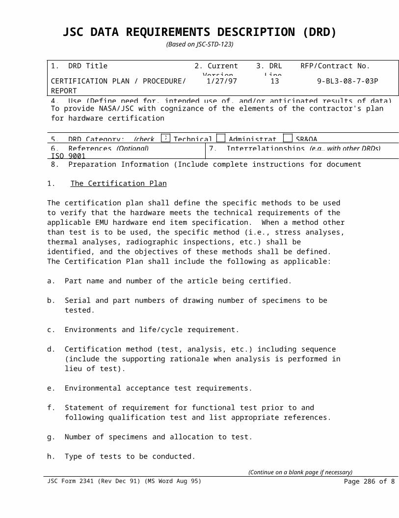
JSC DATA REQUIREMENTS DESCRIPTION (DRD)(Based on JSC-STD-123)
1. DRD Title 2. Current Version Date
3. DRL Line
RFP/Contract No.
ENGINEERING CHANGE ORDER 1/27/97 36 9-BL3-08-7-03P
4. Use (Define need for, intended use of, and/or anticipated results of data)To establish the policies required for originating and processing ECO’s (Engineering Change Orders) which initiate and change drawings, lists of materials and changes other related released documents which define a product configuration.
5. DRD Category: (check one) Technical Administrative SR&QA6. References (Optional) 7. Interrelationships (e.g., with other DRDs) (Optional)CSD-SH-021 Rev A8. Preparation Information (Include complete instructions for document preparation)
1. SCOPE :
The contractor shall prepare Engineering Change Orders which shall satisfy the requirements of CSD-SH-021.
2. CONTENT :
The contractor’s internal control procedures shall act to ensure the following:
a. Changes to engineering documentation defining a product configuration shall be accomplished only by a released ECO.
b. The use of marked drawings, specification/assembly drawings, and/or instructions for fabrication without an approved ECO is prohibited. Verbal requests for, or authorization of, engineering changes shall not be accepted or granted.
c. An ECO shall be used to effect authorized changes to existing documents and to document change proposals as an Engineering Change Proposal (ECP) to the customer.
d. No more than 10 ECO’s, Class I/II, shall accumulate against a released drawing without a revision incorporating the ECO’s. Class III ECO’s will not be accumulated. The drawings will be revised to incorporate each Class III ECO as it is approved.
e. Provide control of ECO’s through initiation and maintenance of an ECO log.f. Sequential numbering system for ECO and revision control.g. Documents submitted for changes to existing documents are authorized by an
approved ECO, and the required signatures are contained on appropriate documents.
The contractor will determine if a change is Class I, II, or III in accordance with CSD-SH-021.
3. FORMAT : The format of the ECO to be used shall contain the following data:
a. Drawing titleb. ECO No.c. Class of Changed. Authorizing/affected documents
(Continue on a blank page if necessary)JSC Form 2341 (Rev Dec 91) MS Word (Aug 95)
J-1-286
JSC DATA REQUIREMENTS DESCRIPTION (DRD)(Based on JSC-STD-123)
e. Drawing numberf. EMU hardware Numberg. Material dispositionh. Drawing revision
i. Effectivity - production/retrofitj. Reason and nature of changek. Technical descriptionl. ECP reference, if applicablem. Customer representative signature and date
The contractor may include data that is required for in-house control.
(Continue on a blank page if necessary)JSC Form 2341 (Rev Dec 91) MS Word (Aug 95)
J-1-287

JSC DATA REQUIREMENTS DESCRIPTION (DRD)(Based on JSC-STD-123)
1. DRD Title 2. Current Version Date
3. DRL Line
RFP/Contract No.
ENGINEERING AND ASSOCIATED LISTS DRAWINGS
1/27/97 37 9-BL3-07-703P
4. Use (Define need for, intended use of, and/or anticipated results of data)To establish the requirements for the preparation or revision of all (Type I) drawings and associated lists provided by a contractor (Type I drawings shall not be prepared for any end item not being developed by or for the Government).
5. DRD Category: (check one) Technical Administrative SR&QA6. References (Optional) 7. Interrelationships (e.g., with other DRDs) (Optional)CSD-SH-021/Rev A, MIL-STD-100B & 1000A8. Preparation Information (Include complete instructions for document preparation)
1. Prime Contractor Data. The contractor shall prepare a complete set of original engineering drawings in accordance with MIL-D-1000, CSD-SH-021, MIL-STD-100, and as contractually required and specified herein for the end item(s) under contract. The preparation, change, and format shall be, as a minimum, as defined in the following paragraphs. Drawings will be designated by NASA as Type I or Type II.
2 Vendor Data (all tier vendors). The prime contractor shall provide in purchase order(s) or contract(s) to vendors a requirement for preparation of engineering data for all vendor item(s) in specified format, except when the vendor designs or develops an end item, as a result of the prime contractor's purchase order or contract, in which case drawings shall be prepared in vendor format.
3 Standard Commercial Parts. When standard commercial non-repairable end items and hardware (such as hinges, locks, light bulbs, resist capacitors, tube sockets, hoses, nuts, bolts, and screws) not covered by Military Standards or Industrial Association Standards are used by the contractor exactly as procured from the supplier or manufacturer, type I data need not be prepared for these parts provided they are described on the assembly drawing in concise and sufficient detail to enable the government to identify and procure from commercial sources. When the end item is not described in accordance with this criteria, reference shall be made to the end item, the supplier or manufacturer's name, address, part number, and catalog number on the drawings, if the catalog defines the part in sufficient detail to enable the government to identify and procure the end item. If suitable catalog data is not available, or the manufacturer's existent drawing does not comply with this requirement, a specification source control drawing shall be prepared for the end item.
4 Interchangeability Marking. Engineering drawings required to be furnished for component parts shall be marked to indicate the approved interchangeability or replaceability status. The engineering drawings to be marked shall be limited to those parts required by MIL-STD-100 to be listed in the interchangeability and replaceability working list (when contractually required). New part numbers shall be assigned to identify parts which change status; i.e., configuration of end item is improved to a higher
(Continue on a blank page if necessary)JSC Form 2341 (Rev Dec 91) MS Word (Aug 95)
J-1-288

JSC DATA REQUIREMENTS DESCRIPTION (DRD)(Based on JSC-STD-123)
degree of replaceability, or from replaceable to interchangeable.
5 Revisions to Government-Furnished type I Data. When Type I engineering data exists for the end items being procured, the government will furnish to the contractor either reproducible (microfilm aperture cards, roll microfilm, or paper), nonreproducibles,, stable material reproductions, or the originals on a loan basis. When the originals are retained by the Government, all of the revised drawing(s) will be forwarded to the prime contractor, if required. When the contractor or vendor determines revisions to type I data are required, the prime contractor shall immediately prepare an engineering change request describing the changes required, and forward it to the procuring activity for approval. If needed, in order to fully describe the change, a marked-up, non-reproducible drawing or sketch shall also be forwarded. After approval, the contractor shall, when requested, prepare any new or revised drawing that may be required or which results from engineering or manufacturing process changes. This also applies to those changes that are not covered by Engineering Change Proposal (ECP) action.
NOTE
When revisions are not required, the contractor shall providea certification that no deviations have been made from, or modifications made to, the engineering drawings furnished to the contractor. If illustrated parts breakdown, technical manuals, or technical directives are changed to reflect changes that affect engineering drawings, the above paragraph
applies.
6 Drawing Number Assignments. Each contractor drawing shall be assigned a number by the contractor or vendor and should be recorded to prevent confusion, skipping, etc. A number once assigned shall never be reused for another assignment but shall be canceled when no longer required.
7 Federal Manufacturers Code. The code identification number data will be applied by the design activity responsible for the end item delineated on the drawing.
8 Application Information. Application and next higher assembly information shall be specified on all drawings in an appropriate block near or adjacent to the title block. Such information may, however, be recorded in list form. When in list form, it shall be cross-referenced to the applicable drawing. Top assembly drawings shall indicate "AS ALLOCATED" in the "NEXT ASSEMBLY" column of the application block.
10 Signature Approval. The signature of the draftsman, checker, and engineer shall be required to indicate the contractor(s) approval. The Government Design Activity's spaces shall provide NASA approval and authentication. Responsibility for NASA approval and authentication may be delegated to the NASA plant representative or DCMC.
11 The original drawings shall be furnished at the termination of the contract unless otherwise stated in the contract Data Requirement List (DRL).
(Continue on a blank page if necessary)JSC Form 2341 (Rev Dec 91) MS Word (Aug 95)
J-1-289

JSC DATA REQUIREMENTS DESCRIPTION (DRD)(Based on JSC-STD-123)
a. Packing the originals shall be Level "C" in accordance with specification MIL-D-1000.
b. None of the original drawings shall be folded and shall be shipped flat or rolled. The drawings shall be shipped FOB from the prime or vendor/subcontractor plant on U.S. Government Bills of Lading (GBL), commercial bills of lading, or when dimensions and cube size permit, by mailing indicia via U.S. Postal Service. Mailing indicia and U.S. GBL's shall be obtained from cognizant transportation officer. All modes of delivery are acceptable except regular railway freight.
12 The effectivity of drawings and associated lists for vehicle(s), stages, and other hardware shall be indicated as required.
(Continue on a blank page if necessary)JSC Form 2341 (Rev Dec 91) MS Word (Aug 95)
J-1-290

JSC DATA REQUIREMENTS DESCRIPTION (DRD)(Based on JSC-STD-123)
1 DRD Title 2. Current Version Date
3. DRL Line
RFP/Contract No.
FRACTURE CONTROL PLAN 1/27/97 38 9-BL3-08-7-03P
4. Use (Define need for, intended use of, and/or anticipated results of data)Prevention of structural failure due to crack-like flaws on pressure vessels designated critical to crew or vehicle survival by application of fracture control.
5. DRD Category: (check one) Technical Administrative SR&QA6. References (Optional) 7. Interrelationships (e.g., with other DRDs) (Optional)
8. Preparation Information (Include complete instructions for document preparation) 1. Pressure vessels are designated fracture critical. A pressure vessel is defined as a container for compressed fluid that would release more than 14.250 foot-pounds (0.01 pound equivalent of TNT) based on the adiabatic expansion of a perfect gas to ambient conditions. The equation to be used for this calculation is:
W = Po V Po 1- -1-1 PF
2. A Fracture Control Plan shall be prepared in accordance with SE-R-0006, paragraph 2.4, for all pressure vessels as defined in 1 above.
3. A Fracture Control Plan for composite pressure vessels metal liners with filament overwrap shall be prepared as follows:
a. Use the general requirements of SE-R-0006, paragraph 2.4.
b. In addition, composite pressure vessels shall be designed to have a leakage mode of failure in the liner at maximum operating pressure using fracture mechanics analyses.
(Continue on a blank page if necessary)JSC Form 2341 (Rev Dec 91) MS Word (Aug 95)
J-1-291

JSC DATA REQUIREMENTS DESCRIPTION (DRD)(Based on JSC-STD-123)
1. DRD Title 2. Current Version Date
3. DRL Line
RFP/Contract No.
DEVELOPMENT TEST(S) PLAN 1/27/97 39 9-BL3-08-7-03P
4. Use (Define need for, intended use of, and/or anticipated results of data)To provide the basic outline for definition of tests to be performed on all new or modified EMU hardware necessary to undergo development test and evaluation to be designed by NASA.
5. DRD Category: (check one) Technical Administrative SR&QA6. References (Optional) 7. Interrelationships (e.g., with other DRDs) (Optional)
8. Preparation Information (Include complete instructions for document preparation)
1. SCOPE :
The contractor shall prepare and submit a development test(s) plan outlining the overall contractual program test planning, including a description of individual test programs, planning factors, objectives, and relative schedules. This plan shall be in response to development tests requested by NASA.
2. CONTENT:
The plan shall be submitted in two sections. The first section, the development test requirements section, include the following for all development testing:
a. Introductionb. Purpose of documentc. Background (baseline information, prior tests, etc.)d. Approach (development only, pre-declared certification, similarity, analysis, etc.)e. Test objectivesf. Test article descriptiong. Facility requirements including special test equipment and instrumentationh. Organizational responsibilitiesi. Schedule
The second section, the implementation section, can be submitted for each test or collectively, and shall include the following:
a. Introduction (background, objectives, and product)b. Test description (overview and approach, test article definition)c. Test profile (environmental, etc.)d. Instrumentation (accuracy, calibration, quantity, location)e. Data processing (real-time, post-test)f. Real-time support responsibilitiesg. Analysis plan (pretest, real-time, post-test)h. Identification of hardwarei. Materials listsj. Pass/fail criteria
(Continue on a blank page if necessary)JSC Form 2341 (Rev Dec 91) MS Word (Aug 95)
J-1-292

JSC DATA REQUIREMENTS DESCRIPTION (DRD)(Based on JSC-STD-123)
3. WAIVER STATEMENT: For specific low fidelity testing (such as breadboard DCM), the NASA technical monitor may waiver the requirement for the second section.
(Continue on a blank page if necessary)JSC Form 2341 (Rev Dec 91) MS Word (Aug 95)
J-1-293

JSC DATA REQUIREMENTS DESCRIPTION (DRD)(Based on JSC-STD-123)
1. DRD Title 2. Current Version Date
3. DRL Line
RFP/Contract No.
MATERIALS CONTROL AND VERIFICATION PROGRAM PLAN / MATCO
1/27/97 40 9-BL3-08-703P
4. Use (Define need for, intended use of, and/or anticipated results of data)To define the objectives, procedures, logic, and management controls of the contractor’s material control and verification program, and the contractor’s interfaces with NASA necessary in the operation of the plan.
5. DRD Category: (check one) Technical Administrative SR&QA6. References (Optional) 7. Interrelationships (e.g., with other DRDs) (Optional)SE-R-0006B NHB 8060.1B Program Management Plan8. Preparation Information (Include complete instructions for document preparation)
1. Materials Control And Verification Plan
A document shall be provided which defines the objectives, logic procedures, required actions, responsibilities, and management controls the contractor shall use in establishing and maintaining a Materials Control and Verification Program. The plan shall describe the contractor’s activities involved in the identification, evaluation, documentation, and reporting usage of materials. It shall define the necessary interfaces with NASA in the operation of this plan. As a minimum, the plan shall cover the following:
a Contractor’s Organization - Authority shall be assigned to an individual or group who shall be responsible for review and approval of all materials called out on all drawings prior to release and that these materials meet the requirements of the reference documents.
b Materials Identification - Identification and documentation of material used, both in original design and in any change.
c Usage Evaluation - Documentation of material uses and the comparison of test data to establish selection and test requirements.
d Testing - Logic, procedures, and data documentation for any proposed test program to support materials screening and verification testing. Any material testing to be performed by the contractor will require prior NASA approval.
e Hazard Removal - Procedure involved in the removal of identified hazards.
f Deviation Procedures - Procedures involved in documenting and approving materials that do not meet the established requirements but are proposed for use in the spacecraft due to lack of replacement materials or other considerations.
g As-Built Control - Procedures involved in assuring that no material hazards are introduced between initial design and operational phase completion.
h Formal Review Procedures - Procedures used to summarize the status of materials to
(Continue on a blank page if necessary)JSC Form 2341 (Rev Dec 91) MS Word (Aug 95)
J-1-294

JSC DATA REQUIREMENTS DESCRIPTION (DRD)(Based on JSC-STD-123)
permit certification of acceptability of a given design or a given configuration at NASA designated hardware milestone reviews, such as PDR’s, CDR’s, CARR’s, FRR’s, etc. The contractor shall have available the following information in support of the end item milestone reviews as applicable: Standard Materials Worksheet packages, Materials Deviations Summary (Drawings and Drawing Tree), Material Test Data and Usage Rationale Summary, Materials Review Board Action Status, Preliminary Materials Lists, and Final Materials Lists.
i New Technology - Identify areas of new test technology or technique improvement for consideration.
The contractor shall define in the control plan a systematic and continuing program to report and control material use, status, test, evaluation, substitution, and verification. The final control plan shall be approved by NASA.
2. Materials Analysis, Tracking And Control (MATCO)
The MATCO system shall provide materials identification, tracking, usage control, and information retrieval related to both as-designed and as-built configurations, including any materials added by process specifications, engineering orders, material review dispositions, or repair actions.
MATCO materials usage evaluation and analysis information submitted for material control verification shall include the following information”
a Materials identification, including the contractor’s material index number, material manufacturer’s name, material designation, and material specification.
b Materials usage information, including detailed drawing and dash numbers, next assembly
drawing numbers, applicable material control requirements, vehicle effectivity, and end item usage quantities.
c Materials information, including materials weight (non-metals), surface area (non-metals), flammability usage evaluation, offgassing evaluation, thermal vacuum stability evaluation, age/limited use life evaluation, stress corrosion evaluation, material/fluid compatibility evaluation, corrosion evaluation, materials supporting documentation, materials test documentation, and applicable materials waivers or deviations.
(Continue on a blank page if necessary)JSC Form 2341 (Rev Dec 91) MS Word (Aug 95)
J-1-295

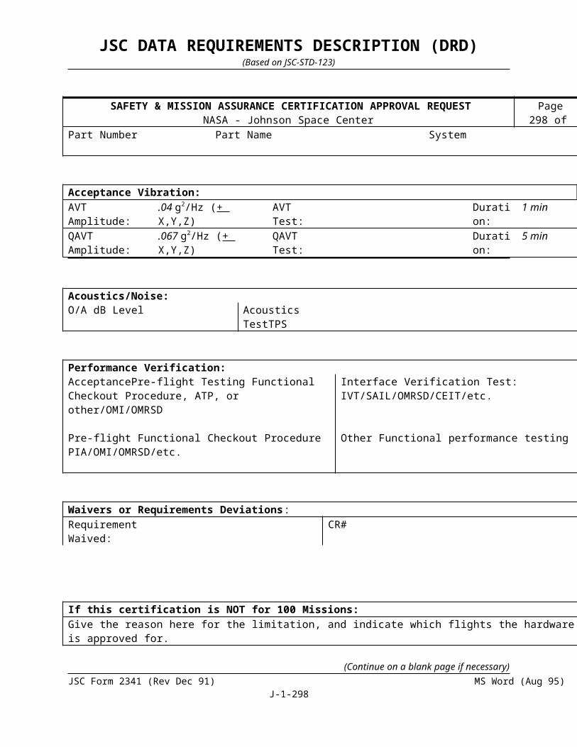
JSC DATA REQUIREMENTS DESCRIPTION (DRD)(Based on JSC-STD-123)
1. DRD Title 2. Current Version Date
3. DRL Line Item No.
RFP/Contract No.
PRELIMINARY DESIGN REVIEW AND CRITICAL DESIGN REVIEW REPORT
1/31/97 41 9-BL3-08-7-03P
4. Use (Define need for, intended use of, and/or anticipated results of data)To provide a summary of agreement, action approvals conclusions, and identification design changes resulting from the design review
5. DRD Category: (check one) Technical Administrative SR&QA6. References (Optional) 7. Interrelationships (e.g., with other DRDs) (Optional)CSD-SH-021, REV. A8. Preparation Information (Include complete instructions for document preparation)
1. CONTENT
a. The design review report shall contain, but not be limited to, the agenda, review topics, Review Item
Disposition (RID) log, a copy of each RID, and minutes of the review meeting. The report shall also contain summaries of all agreements for future actions, areas of major disagreements, identification of design changes, and conclusions reached during the review. The review report shall list all documents forming the basis for system criteria, definition of subsystem requirements, and the development of subsystem design. The conclusions of the review report shall be comprehensive and shall include the approvals issued by the design review board concerning the engineering effort.
b. The report shall document the rationale for the acceptance and rejection of the concepts considered during the review.
c. The Critical Design Review (CDR) report, in addition to the above, shall include as a minimum the following:
(1) Identify the item subjected to the CDR by drawing number, part number, and serial number.
(2) The CDR report shall identify in detail the certification baseline of each EMU hardware component subject to the CDR.
(3) Identification of all approved engineering data (i.e., drawings, specifications, deviations, etc.) required to fabricate the item subjected to CDR. Any special provisions made during procurement of the item shall be identified.
(4) Identification of the physical and functional interface relationship and the interface control document nomenclature (title and number).
(5) Identification of the applicable EMU hardware or S/AD for the CDR item(s). This shall include title, revision letter and date, and any other information to exactly define the issue approved at CDR.
(6) Date of the CDR and any other pertinent information related to the CDR that would prove of interest in evaluation of the CDR.
(Continue on a blank page if necessary)JSC Form 2341 (Rev Dec 91) MS Word (Aug 95)
J-1-298
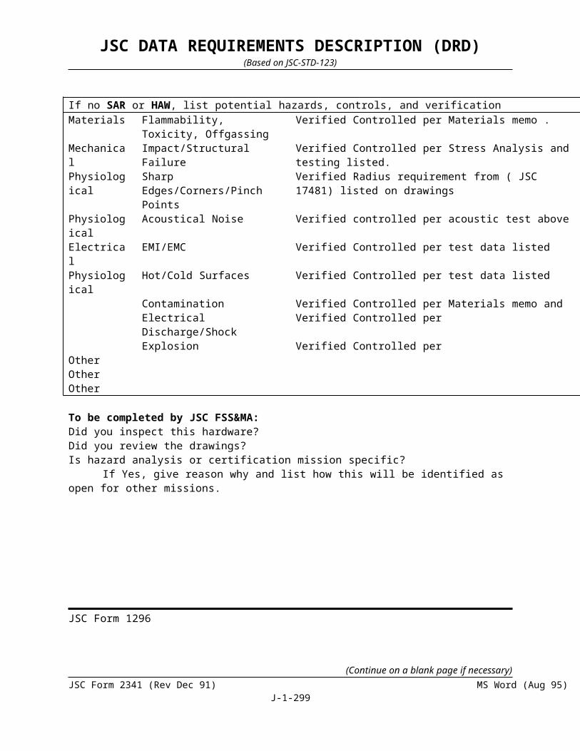
JSC DATA REQUIREMENTS DESCRIPTION (DRD)(Based on JSC-STD-123)
(7) All approved and released Class I engineering changes shall be identified by ECP and ECO number.
2. APPROVAL: The design review report shall be concurred upon by the contractor approval authority.
3. FORMAT: The report may be submitted in an outlined narrative form.
(Continue on a blank page if necessary)JSC Form 2341 (Rev Dec 91) MS Word (Aug 95)
J-1-299

JSC DATA REQUIREMENTS DESCRIPTION (DRD)(Based on JSC-STD-123)
1. DRD Title 2. Current Version Date
3. DRL Line
RFP/Contract No.
PRELIMINARY DESIGN REVIEW DATA PACKAGE
1/27/97 42 9-BL3-08-703P
4. Use (Define need for, intended use of, and/or anticipated results of data)To provide the preliminary design documentation for review and analysis of EMU hardware end item specification requirements.
5. DRD Category: (check one) Technical Administrative SR&QA6. References (Optional) 7. Interrelationships (e.g., with other DRDs) (Optional)CSD-SH-021 Rev A8. Preparation Information (Include complete instructions for document preparation)
1. The contractor shall prepare and submit a data package, including a complete documentation list, presenting for the PDR (Preliminary Design Review), the specification requirements for EMU hardware end item.
2. The data package listing shall include, but not be limited to, the documentation indicated below. This documentation shall be approximately 10-20 design complete.
a. Prescribed Program Development Plan(s).b. End Item Design Criteriac. Preliminary Interface Control Documentation.d. Model Specification Draft (Part II).e. Preliminary Layouts.f. Preliminary Schematics.g. Preliminary Engineering Analyses.h. End Item Functional Control.i. Preliminary Diagrams.j. Preliminary Charts.
3. The physical documents shall be in packages prepared in sufficient draft form and listed by the top number precedence of hardware downward to the last expectant component.
4. The document listing shall provide a contractor signature block to verify the contents and responsible area(s).
(Continue on a blank page if necessary)JSC Form 2341 (Rev Dec 91) MS Word (Aug 95)
J-1-300

JSC DATA REQUIREMENTS DESCRIPTION (DRD)(Based on JSC-STD-123)
1. DRD Title 2. Current Version Date
3. DRL Line
RFP/Contract No.
SPECIFICATION/ASSEMBLY DRAWINGS (S/AD)
1/27/97 43 9-BL3-08-7-03P
4. Use (Define need for, intended use of, and/or anticipated results of data)To provide instructions for preparation of S/AD's as to format, organization of date, and approval requirements. S/AD's contain essentially the same data as EMU hardware end item specifications, but in a more condensed format, thereby reducing document preparation and maintenance.5. DRD Category: (check one) Technical Administrative SR&QA6. References (Optional) 7. Interrelationships (e.g., with other DRDs) (Optional)NASA JSC 07700, Vol. IV and MIL-STD-1008. Preparation Information (Include complete instructions for document preparation)
1. S/AD's shall be prepared as depicted in the following paragraphs:
a. FORMAT
S/AD's shall be prepared on engineering drawing sheets described in MIL-STD-100. The first part of the S/AD will be the top assembly drawing. (If the data normally incorporated in the top assembly drawing extends to more than one sheet, all sheets must be the same size.) The second part of the S/AD will be the specification and may be of a different size. If the data in the specification part extends to more than one sheet, all these sheets must be the same size.
b. ORGANIZATION OF DATA
S/AD's shall conform in general to the drawing standard, except as described herein.
(1) Top Assembly Drawing
The top assembly drawing shall consist of the following (all references are to MIL-STD- 100):
(a) Title block (Fig. 7)
(b) Revision block (Fig. 9)
(c) Dimensional notes (Fig. 11)
(d) Application block (Fig. 12)
(e) Materials list providing configuration dash number, quantity per assembly of subordinate parts/materials, subordinate part numbers, materials standards, name and description, material types, and specification. When separate parts lists are used as part of the drawing system, this
(Continue on a blank page if necessary)JSC Form 2341 (Rev Dec 91) MS Word (Aug 95)
J-1-301
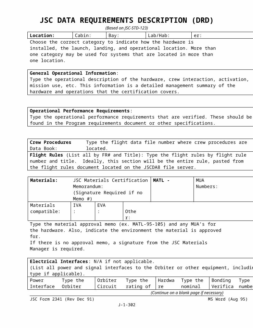
JSC DATA REQUIREMENTS DESCRIPTION (DRD)(Based on JSC-STD-123)
data shall be contained in the parts list and reference thereto made on the first sheet of the drawing.
(f) Flag notes applying to specific applications or parts indicated on the drawing, entered in numerical order.
(g) General notes applying in general to the assembly or specifying applicable documents, procedures, or specifications.
(h) A three view envelope drawing with all critical dimensions, interface points or other limits as may be required. This will indicate the ICD(s) affected should any parameter change. Should incorporation of the three view drawing on Sheet 1 require space allocated to items e, f, and g, the data of these items shall be incorporated on subsequent sheets.
(2) Specification
The format and requirements of the specification shall be as follows:
1.0 SCOPE
This S/AD establishes the requirements for design, performance, and testing of (enter official end item nomenclature).
(Mandatory statement)
2.0 APPLICABLE DOCUMENTS
Only those documents of the revision indicated hereon apply to the extent specified on the drawing. In case of conflict between the
drawing and referenced documents, the approved drawing shall take precedence. (Mandatory statement)
3.0 DESIGN REQUIREMENTS
This section shall have the following heading:
DESIGN DESIGN APPLICABLE TEST
NOTES REQUIREMENTS CERT PDA PIA
1. Design notes shall be in numerical order, provide the performance and design requirements as specified by
NASA for the component/end item. Each parameter which must be verified during any of the specific tests indicated in the right hand column shall require a numerical entry. The requirements to be listed include, but are not limited to:
Operational performancePressures, flows, outputs (mechanical or electrical) or other
(Continue on a blank page if necessary)JSC Form 2341 (Rev Dec 91) MS Word (Aug 95)
J-1-302

JSC DATA REQUIREMENTS DESCRIPTION (DRD)(Based on JSC-STD-123)
requirementsUseful life (include: shelf, operational, limited life items)Safety requirementsNatural and induced environmentsInterface requirementsReference specifications, documents, standards, etc., as
applicable within specific requirementsNon-metallic materials, parts, and processesElectromagnetic compatibilityCorrosion resistanceRiveting, fastening, or other critical assembly dataIdentification and marking criteriaWeight
(NOTE)
Entries under the above need not duplicate items which are displayed on other sheets of the drawing unless verification is required as a part of one of the tests.
2. Enter the specific test requirements where the criteria is to be verified. Items indicated for certification test are normally those associated with first article verification of design and performance. Items indicated under PDA and PIA are normally those associated with verification of as-designed vs. As-built configurations, plus those requirements to be reverified, e.g., antenna gain, or output.
4.0 TEST REQUIREMENTS AND PLAN
All testing shall be conducted with 100 percent quality assurance inspection in accordance with the contractor's Quality Plan (add document number). Verification of data shall be recorded on Test Data sheets. (Mandatory statement)
This section shall have the following heading:
TEST TEST REQUIREMENT/ DESIGN NOTE PERFORMNOTE PARAMETER VERIFIED AT
1. Indicate the test requirement/parameter/method to be used for verification of each design note of Section 3.C. List as many separate tests as may be required. Reference may be made to other approved test documentation if the test data verification is performed by that document, i.e., MIL-STD-810B, Method XXX. Provide quantitative data with tolerances, when applicable.
2. Provide the design note number of Section 3.0 to be verified and the
(Continue on a blank page if necessary)JSC Form 2341 (Rev Dec 91) MS Word (Aug 95)
J-1-303

JSC DATA REQUIREMENTS DESCRIPTION (DRD)(Based on JSC-STD-123)
test(s) at which it is performed. Test procedures shall be prepared with Test Data Sheets for PDA/PIA tests and ______________ for certification testing. These procedures shall provide the test performance steps, test setup, allow for insertion of observed data vs. Required data, serial numbers, part numbers, etc., and shall be cross referenced to this section. (Mandatory statement)
(NOTE)
Section 3.0 (Design Requirements) and Section 4.0 (Test Requirements and Plan) may be combined. When these sections are combined, the following heading/format for these two sections shall be used:
3.0/ 4.0 DESIGN DATA PACKAGE REQUIREMENTSDESIGN DESIGN TEST REQUIREMENTS PERFORMNOTES REQUIREMENTS AND PLAN AT
5.0 ACCEPTANCE DATA PACKAGE REQUIREMENTS
The ADP for each end item shall be initiated at completion of fabrication and shall contain: (list data specified by the contract). (Mandatory statement)
6.0 PROBLEM REPORTING
Problem reporting requirements are initiated at PDA and extend through end item useful life. Submit to: (Enter data specified in the contract). (Mandatory statement)
7.0 CHANGE CONTROL
Class I and II items are subject to formal change control.
8.0 PREPARATION FOR DELIVERY
CPPHSS (cleaning, preservation, packaging, handling, storage and shipping) requirements shall be indicated. Reference to a NASA approved CPPHSS Manual which includes the requirements for the end items may be made. Peculiar requirements should be included herein or provided as a separate portion of the CPPHSS Manual. These requirements may be the need for special containers, mounting fixtures, or procedures for transportation of dangerous or toxic items by commercial carriers.
9.0 CRITICALITY
(Continue on a blank page if necessary)JSC Form 2341 (Rev Dec 91) MS Word (Aug 95)
J-1-304

JSC DATA REQUIREMENTS DESCRIPTION (DRD)(Based on JSC-STD-123)
State that the end item is a criticality I, II, or III item. In accordance with the contract or data requirements give the document number for the single point FMEA and critical items list, and the safety hazard analysis; if these are not required, then so state.
10. SR&QA REQUIREMENTS
State the SR&QA requirements briefly, individually or combined. Reference may be made to other approved documentation.
Following paragraph 10.0, additional data such as tables may be included to provide a clear picture of requirements. These may be vibration, natural vs. Induced environments, etc. Reference to the tables shall be made in the applicable portions of 3.0 through 10.0 above.
Following the last portion of the specification data, include provisions for approval block signatures as indicated below:
PDR
Contractor - one spaceNASA - one space
CDR
Contractor - one spaceNASA - a minimum of six spaces
The CDR approval block shall replace the PDR approval block and be the only approval block on the specification portion.
2 The "specification data" shall be approved in two steps as follows:
a. PDR - That data necessary for "design and performance" of the end item shall be approved by the contractor's Program Manager and NASA's PDR Board Chairman.
b. CDR - The complete specification portion shall be approved by the contractor's Program Manager, the NASA Technical Monitor, CDR Board Chairman, Reliability and Quality Engineering representatives, Configuration Manager, and Shuttle Program Office representative.
c. The NASA technical monitor shall sign all sheets of the drawing at CDR prior to release.
3 S/AD is a Type I drawing subject to formal change control upon approval.
(Continue on a blank page if necessary)JSC Form 2341 (Rev Dec 91) MS Word (Aug 95)
J-1-305

JSC DATA REQUIREMENTS DESCRIPTION (DRD)(Based on JSC-STD-123)
(Continue on a blank page if necessary)JSC Form 2341 (Rev Dec 91) MS Word (Aug 95)
J-1-306

SECTION J
LIST OF ATTACHMENTS1. DRD Title 2. Current
Version Date3. DRL
Line RFP/Contract No.
STRUCTURAL STRESS ANALYSIS REPORT
1/27/97 44 9-BL3-08-7-03P
4. Use (Define need for, intended use of, and/or anticipated results of data)The stress analysis report is intended to demonstrate that the structural integrity of the hardware meets the design and certification requirements
5. DRD Category: (check one) Technical Administrative SR&QA6. References (Optional) 7. Interrelationships (e.g., with other DRDs) (Optional)ISO 90018. Preparation Information (Include complete instructions for document preparation)
1. The structural stress analysis report is a part of the certification process. The report is intended to demonstrate that the structural integrity of the hardware meets the design and certification requirements.
2. The report should be sufficiently detailed to show that the following have been complied with:
a Proper loads, loading paths, and support locations have been used based on the hardware requirements.
b That materials of construction have been adequately defined.
c Structural attachments, fitting factors, fatigue conditions, fracture mechanics, and stress corrosion factors have been considered. Note: Fracture mechanics will be considered for analysis involving pressure vessels only.
d The analytical approach used should be clearly defined, and it should identify all the assumptions made.
e Sufficient sketches should be included to clearly identify the structure being analyzed.
SECTION J
LIST OF ATTACHMENTS
1. DRD Title 2. Current Version Date
3. DRL Line
RFP/Contract No.
SYSTEM DESIGN AND PERFORMANCE REQUIREMENTS DOCUMENT
1/27/97 45 9-BL3-08-7-03P
4. Use (Define need for, intended use of, and/or anticipated results of data)The purpose of this document is to provide NASA with a current, integrated statement of the system design and performance requirements.
5. DRD Category: (check one) Technical Administrative SR&QA6. References (Optional) 7. Interrelationships (e.g., with other DRDs) (Optional)
8. Preparation Information (Include complete instructions for document preparation)
1. The System Design and Performance Requirements are set forth in this contract.
2. The initial iteration of this document will set forth the requirements now contained in this contract.
3. The contractor shall maintain this document through the contract period of performance in accordance engineering change orders.
4. This document is intended to provide NASA a current, integrated version of the System Design and Performance Requirements for use as a working tool. It is not intended to supersede, replace, or otherwise affect in a contractual manner the requirements set forth in the contract, or changes thereto made pursuant to the “changes” clause of the contract. Accordingly, in the event of any inconsistencies between this document and the contract or changes thereto, the latter shall control.
(Continue on a blank page if necessary)JSC Form 2341 (Rev Dec 91) (MS Word Aug 95) Page 308 of 1

SECTION J
LIST OF ATTACHMENTS
1. DRD Title 2. Current Version Date
3. DRL Line
RFP/Contract No.
CLEANING, PRESERVATION, PACKAGING, HANDLING, STORAGE, AND SHIPPING PROCEDURE
1/27/97 46 9-BL3-08-7-03P
4. Use (Define need for, intended use of, and/or anticipated results of data)To provide detailed procedures for cleaning, preserving, packing, handling, storing, and shipping all contract hardware end items
5. DRD Category: (check one) Technical Administrative SR&QA6. References (Optional) 7. Interrelationships (e.g., with other DRDs) (Optional)ISO 9001 MIL-STD-129F8. Preparation Information (Include complete instructions for document preparation)
1. The contractor shall prepare and submit a document containing detailed step-by-step procedures on cleaning, preservation, packaging, handling, and shipping all EMU hardware and related items.
2. The document shall include, but not be limited to, the following:a. Acceptable cleaners and all other items necessary to perform functions of the
document, such as cleaning pads, cleaning equipment, protective covers, bags, shipping containers, etc.
b. Locations to lift items and areas of precaution.c. Cleaning requirements and method of verification.d. Procedures of cleaning, including disassembly, cleaning, lubrication, and
reassembly.e. Method of packaging, including folding, protective covers, bags in which to place
the equipment, and bag sealing methods.f. Method of packing the bagged items in a carrying case.g. Documentation to place in the carrying case of each item.h. Method of marking in accordance with latest issue MIL-STD-129.
(Continue on a blank page if necessary)JSC Form 2341 (Rev Dec 91) (MS Word Aug 95) Page 309 of 1

SECTION J
LIST OF ATTACHMENTS
1DRD Title 2. Current Version Date
3. DRL Line
RFP/Contract No.
MAINTENANCE AND REPAIR MANUAL/ ILLUSTRATED PARTS LIST
1/27/97 47 9-BL3-08-7-03P
4. Use (Define need for, intended use of, and/or anticipated results of data)To provide maintenance and repair instructions for contract end items.
5. DRD Category: (check one) Technical Administrative SR&QA6. References (Optional) 7. Interrelationships (e.g., with other DRDs) (Optional)
8. Preparation Information (Include complete instructions for document preparation)
1. SCOPE: The contractor shall prepare and submit, to the NASA, a manual covering maintenance and repair of EMU hardware.
The manual shall include, but not be limited to the following:
a A list of special tools, support and facilities equipment, and all other materials necessary to perform maintenance.
b A schedule chart listing the time at which all maintenance is to be performed. This shall also include inspection for required repair, or maintenance or replacement of parts.
c Conditions of environment in which maintenance is to be performed.
d Detailed maintenance procedures which describe removal, disassembly, type of maintenance or repair, cleaning, reassemble, and reinstallation of all parts or subassemblies (also included shall be points of inspection and notes of caution).
e Illustrated part breakdowns showing the details of the part being worked upon.
The contractor shall prepare and submit to NASA a document which has the complete parts breakdown with illustrations showing all parts included in EMU hardware.
2. CONTENT:: The document shall include, but not be limited to, the following:
a. Illustration of EMU hardware with attached list of all assembly part numbers and associated hardware.
Continued breakdown of EMU hardware until all parts are included. All screws, adhesives, threads, etc., shall be identified.
(Continue on a blank page if necessary)JSC Form 2341 (Rev Dec 91) (MS Word Aug 95) Page 310 of 1

SECTION J
LIST OF ATTACHMENTS
1. DRD Title: 2. Current Version
3. DRL Line
RFP/Contract No.:
SAFETY PLAN 19 Mar 96 48 9-BL3-08-7-03P
4. Use: (Define need for, intended use of, and/or anticipated results of data)Establishes system safety tasks and activities to identify, evaluate, and eliminate, or control hazards associated with flight hardware and operations.
5. DRD Category: (check one) Technical Administrative SR&QA6. References: (Optional) 7. Interrelationships: (e.g., with other DRDs) (Optional)See “Reference Documents” under item 8 below.
SMACAR & HR
8. Preparation Information: (Include complete instructions for document preparation)
Reference Documents:NHB 1700.1, Volume 1, as revised, "NASA Safety Policy and Requirements Document"JSCM 1700.1, as revised, "JSC Safety Manual"MIL-STD-882B,"System Safety Program for Systems and Associated Subsystems
and Equipment, General Requirements for"NHB 5300.4, 1D-2,"Safety, Reliability, Maintainability, and Quality Provisions for the
Space Shuttle Program"JSC 17773, as revised, "Instruction for Preparation of Hazard Analyses for JSC
Ground Operations"JSC 17481, as revised, "Safety Requirements Document for Space Shuttle Flight
Equipment"NSTS 22254, as revised, "Methodology for Conduct of Space Shuttle Program
Hazard Analyses"NHB 1700.1 (V1-B & V2) “Guidelines for Mishap Investigation”
1. SCOPE:
The Safety Plan shall addresses safety policy, applicable documents, task descriptions, products, and processes during the design, development, test, production, and operational phases of flight hardware. The Safety Plan shall set forth safety tasks, products, and processes. It serves as a planning and management tool for ensuring safety tasks are performed as an integral part of the design, development, test, production, and operational phases of the end items. Implementation of the Safety Plan shall assure hazards and their consequences are identified, evaluated, and controlled throughout all phases of the program in accordance with NHB 1700.1 (V1-B), “NASA Safety Policy and Requirements Document,” paragraphs 104, 108, and 310. Safety Plans are to be tailored for individual safety engineering projects as integral parts of a formal, disciplined system safety program implemented by NASA and the contractor Safety Plan Requirements.
2. FORMAT and CONTENTS:
1. Introduction2. General. The Safety Plan shall be documented in narrative format and shall:2.a Describe the scope of the project for which the safety engineering activity is to be
(Continue on a blank page if necessary)JSC Form 2341 (Rev Dec 91) (MS Word Aug 95) Page 311 of 1
SECTION J
LIST OF ATTACHMENTStailored.
2.b Describe any interrelationships to other contract requirements, tasks and functional elements
including appropriate cross references to minimize duplication.2.c List the contractor and NASA documents which will be applied either as
directives or as guidance in the conduct of the Safety Plan and related system safety tasks.2.d Identify the system safety engineering requirements, tasks, and responsibilities on an
item-by-item basis in accordance with the schedule.
3.0 Safety Engineering Organization. The Safety Plan shall describe:3.0.a The system safety organization or function within the organization of the contract
including charts to show the organizational and functional relationships and lines of communication.
3.0.b The responsibility, authority, and accountability of system safety personnel and other contractor organizational elements (including subcontractors) involved in the system safety effort. Identify each organizational unit responsible for executing each task. Identify the authority in regard to resolution of all identified hazards. Include the title, address, and telephone number of the System Safety Program Manager.
3.0.c The staffing of the system safety organization for the duration of the project including manpower loading and qualifications of assigned key personnel.
3.0.d The procedures by which the contractor will integrate and coordinate the system safety efforts.
Include methods of dissemination of system safety requirements to action organizations and subcontractors; coordination of subcontractors' system safety programs; integration of hazard analyses; management and engineering reviews; program status reporting; and the identities and charters of any system safety groups.
3.0.e. The process through which contractor management decisions will be made to include notification and subsequent actions for the following: critical and catastrophic hazards; corrective actions taken; mishaps or malfunctions; waivers to safety requirements; and program deviations.
3.0.f. The interfaces between the system safety organization and all other applicable disciplines such as Engineering, Occupational Safety and Health, Reliability, Quality Assurance, Medical Support, etc., at all levels of the project (NASA, contractor, and subcontractor.)
3.1 Safety Project Milestones. The Safety Plan shall:3.1.a Identify safety milestones required to accomplish evaluations of the effectiveness of the
system safety effort at critical safety checkpoints (such as design reviews, self-evaluations, operational readiness reviews, audits, etc.)
3.1.b Provide a contract schedule of safety tasks showing start and completion dates, reports, reviews, and manloading, in relationship to other contract milestones.
3.1.c To preclude duplication, identify integrated system activities (i.e., design analyses, test, demonstrations, etc.) applicable to the system safety program but specified within other engineering tasks. Include as part of this section the estimated system safety manpower loading required to accomplish these integrated tasks.
3.2 Safety Requirements. The Safety Plan shall:
(Continue on a blank page if necessary)JSC Form 2341 (Rev Dec 91) (MS Word Aug 95) Page 312 of 1

SECTION J
LIST OF ATTACHMENTS3.2.a Describe or reference the methods that will be used to identify and apply hazard control
requirements and criteria for the design and operation of equipment, software, and facilities, and for procedures covering all phases of acquisition specified in the schedule. List the safety standards and system specifications which are the sources of safety requirements with which the contractor either is required to comply or intends to adopt as a requirement.
3.2.b Describe the risk assessment procedures including the hazard severity categories, hazard probability (or frequency) levels, the precedence to be followed in satisfying safety requirements. State any qualitative or quantitative measures of system safety which the contractor is required to meet, including a description of the acceptable risk levels. Include system safety definitions which are in addition to those in JSC documents or are unique to the project covered by the Safety Plan.
3.2.c Describe the management controls that shall be used to ensure compliance or justify waivers and deviations with general design and operational safety criteria and the closed loop procedures to ensure hazard resolution and control.
3.3 Hazard Analyses. The Safety Plan shall describe: 3.3.a The analysis techniques and format that will be used in qualitative and quantitative
analysis to identify hazards, their causes and effects, and recommended corrective actions.
3.3.b The depth to which each analysis technique will be used within the system, operation, or scenario being analyzed. This description will include identification of hazards associated with the system, subsystem, components, personnel, support equipment, government furnished equipment, facilities, and their interrelationships in the logistics support, training, maintenance, transportability, operational environments, and phase out or disposal.
3.3.c The integration of subcontractor hazard analyses and techniques within the overall project
including contractor hazard analyses.3.3.d The techniques to be used to establish a single closed loop tracking system.
3.4 Safety Data. The Safety Plan shall:3.4.a Describe the approach for researching, disseminating, and analyzing pertinent
historical hazard or mishap data.3.4.b Identify deliverable data and the level of approval required for customer acceptance.
Attach a copy of the appropriate sheets from the data requirements list (DRL) of the schedule.
3.4.c Identify safety related non-deliverable data and describe the procedures for accessibility by NASA and the retention of data.
3.5. Safety Verification and Audits. The plan shall describe:3.5.a The verification and audit requirements and procedures for ensuring that the objectives
and requirements of the system safety program have been adequately demonstrated and implemented.
3.5.b The procedures for ensuring feedback of safety-pertinent information for management and
engineering review and analysis.3.5.c The review procedures established by the contractor's system safety organization to
ensure safe
(Continue on a blank page if necessary)JSC Form 2341 (Rev Dec 91) (MS Word Aug 95) Page 313 of 1

SECTION J
LIST OF ATTACHMENTS conduct of hazardous tests with particular emphasis on those involving human test
subjects.
3.6 Training. Describe techniques and procedures to be used by the contractor to ensure that the objectives and requirements of the system safety program are implemented in training for engineers, test subjects, technicians, operators, and support (including maintenance) personnel.
4.0 Safety Review Process.4.0.a The safety process shall be based on the hardware design and development schedule.
Hardware and safety engineers will work all safety issues associated with the hardware. Safety analysis begins at the hardware’s concept phase and continues through the life cycle of the hardware.
4.0.b For Prime Contractor integrated hardware items, the safety process will include safety data deliveries to the Prime in support of the Safety Review Panel (SRP) and Incremental Design Review (IDR) flight group schedules. The Prime will perform the integrated safety analysis for this hardware and present the integrated safety analysis to the Safety Review Panel (SRP).
4.0.c For Non-Prime hardware items, phase safety data packages will be delivered 45 days prior to a scheduled SRP meeting.
4.1 Phase 0 Safety ProcessA Phase 0 Safety Review may be conducted after the Concept Design Review. The hardware and safety engineers will identify the applicable safety requirements and estimate the level and amount of documentation needed with a documentation deliverable schedule. A formal SRP presentation is not required, but may be beneficial for complex hardware items.
4.2 Phase I Safety Process4.2.a Prior to the Phase I Safety Review and the Preliminary Design Review (PDR), the
hardware and safety engineers will identify all potential inherent hazards, fault hazards, operational hazards and causes for hazards associated with the hardware. The hazards will then be assessed for severity and likelihood as defined in NSTS 22254 and SSP 30309. Low severity hazards (category III and lower) will result in documentation in the SAR. High severity hazards will be identified in the SAR with a formal hazard report written. Controls for hazards will be employed with preliminary methods identified to verify all hazard controls.
4.2.b At the PDR, when approximately 10% of the design is complete, all potential hazards, causes and effects will be documented. Review item discrepancies will be written when safety requirements have not been met or adequately controlled. The RID board will disposition the RIDs and determine if any design change solution is available.
4.2.c Once any changes from the RIDs and other comments have been incorporated, the SAR and HRs will be taken by the hardware engineer and the safety engineer to be reviewed by the ISS SRP or the Shuttle System Safety Review Panel (SSRP). The ISS SRP and the Shuttle SSRP have final signature authority for acceptance of the hazard reports for the Phase I level of maturity.
4.2.d The hardware engineer will continue with the design process for the hardware and perform the
necessary iterations of the hazard analysis as the design matures.
(Continue on a blank page if necessary)JSC Form 2341 (Rev Dec 91) (MS Word Aug 95) Page 314 of 1

SECTION J
LIST OF ATTACHMENTS4.3 Phase II Safety Process4.3.1 The Phase II Safety Review is conducted after the Critical Design Review (CDR) when approximately 90% of the design is complete. 4.3.2 The SAR and HRs shall be completed so that:4.3.2.a All system level, assembly, operational and interface hazards, and hazard causes
have been identified; 4.3.2.b A means for eliminating, reducing, or controlling the risk has been defined and
implemented; and 4.3.2.c Specific verification methods have been finalized. 4.3.3 The hazard reports will be formally presented during the CDR presentation.
Verification test procedures related to hazard controls and retention rationale will be reviewed as well. 4.3.4 The RID board will disposition new RIDs and determine if any design change solution is
available. Once any changes from the RIDs and other comments have been incorporated, the SAR and HRs will be taken by the hardware engineer and the safety engineer to be reviewed by the ISS SRP or the Shuttle SSRP.
4.3.4 The ISS SRP and the Shuttle SSRP have final signature authority for acceptance of the hazard reports for the Phase II level of maturity.
4.4 Phase III Safety Process4.4.a The Phase III Safety Review is accomplished after the Design Certification Review (DCR). The safety analysis and safety verification activities should be complete for the hardware to allow safety certification and program management acceptance. 4.4.b The hardware engineer, safety engineer, and the appropriate review panel approves the hardware certification report, and signs off the completed safety documentation. 4.4.c The hardware engineer is responsible for the technical content, the S&MA engineer verifies the information is correct, and the review panel provides the management signature.
5.0 Appendices5.1 Safety Analysis Report (SAR): See data requirements description on “SARs.”5.2 Hazard Report (HR): See data requirements description on “HRs.”5.3 Mishap and Investigation Reports: See data requirements description on “Mishap
and Investigation Reports.”
(Continue on a blank page if necessary)JSC Form 2341 (Rev Dec 91) (MS Word Aug 95) Page 315 of 1

SECTION J
LIST OF ATTACHMENTS
1. DRD Title 2. Current Version Date
3. DRL Line
RFP/Contract No.
MATERIAL REVIEW BOARD RECORDS 1/27/97 49 9-BL3-08-7-03P
4. Use (Define need for, intended use of, and/or anticipated results of data)To establish minimum requirements for MRB records.
5. DRD Category: (check one) Technical Administrative SR&QA6. References (Optional) 7. Interrelationships (e.g., with other DRDs) (Optional)
8. Preparation Information (Include complete instructions for document preparation)
This Data Requirements Description establishes the type information recorded on MRB report and support documentation associated with the MRB decision.
1. The MRB shall contain, but not be limited to:
a. A unique and traceable number
b. The nomenclature and identification of the non-conforming article or material.
c. A description of the nonconformance and the required characteristic or design criteria
d. Cause or reason for the nonconformance.
e. Remedial actions taken or recommended.
f. Disposition reference Non-conforming Material Report.
g. Initial Nonconformance Report number, if applicable.
h. Signatures of authorized personnel.
2. The contractor shall maintain a record of all decisions and support documentation associated with the MRB decision.
3. The MRB Report shall be prepared and submitted as specified on NASA Form 1106.
(Continue on a blank page if necessary)JSC Form 2341 (Rev Dec 91) (MS Word Aug 95) Page 316 of 1

SECTION J
LIST OF ATTACHMENTS
1. DRD Title 2. Current Version Date
3. DRL Line
RFP/Contract No.
PRE-INSTALLATION TEST/ACCEPTANCE PLAN AND PROCEDURE (PIA)
1/27/97 50 9-BL3-08-7-03P
4. Use (Define need for, intended use of, and/or anticipated results of data)To define the plan and procedural requirements for pre-installation acceptance of items prior to flight or test.5. DRD Category: (check one) Technical Administrative SR&QA6. References (Optional) 7. Interrelationships (e.g., with other DRDs) (Optional)JSCM 5312 ISO 9001 8. Preparation Information (Include complete instructions for document preparation)
1. This DRD establishes the requirements for the preparation of plans and procedures in a format acceptable to NASA which shall contain the inspection and test requirements to ensure that the equipment has not been degraded or damaged due to mishandling or excessive storage life.
2. The Plan shall provide:
a. Facility Requirementsb. Special tools and test equipmentc. Support Equipmentd. Test philosophye. Test objectivesf. Test requirementsg. Test methodsh. Retest requirementsi. Test sequencej. Acceptance and rejection criteriak. Failure notification criteria
3. The Procedure shall provide:
a. Test equipment validationb. Safety precautionsc. Related operating proceduresd. Test criteriae. Test setupf. Test conductg. Test data sheetsh. Cleaning requirementsi. Packaging requirementsj. Packaging requirements
(Continue on a blank page if necessary)JSC Form 2341 (Rev Dec 91) (MS Word Aug 95) Page 317 of 1

SECTION J
LIST OF ATTACHMENTS
1. DRD Title 2. Current Version Date
3. DRL Line
RFP/Contract No.
TEST PERFORMANCE SHEET FOR TEST PROCEDURES
1/27/97 51 9-BL3-08-7-03P
4. Use (Define need for, intended use of, and/or anticipated results of data)To prepare test procedures on TPS forms5. DRD Category: (check one) Technical Administrative SR&QA6. References (Optional) 7. Interrelationships (e.g., with other DRDs) (Optional)
8. Preparation Information (Include complete instructions for document preparation)
1. This DRD sets forth instructions for preparing test procedures by Test Performance Sheet (TPS), Form 1225 and TPS continuation sheet, Form 1225A (Rev Sep 76). NASA will furnish these forms to the contractor as required.
2. When a TPS is used in lieu of a formal test procedures document, the following shall be adhered to: the TPS must by self-sufficient in supplying detailed procedural instructions, test set-up requirements, special test equipment requirements, specifications, tolerances, drawings, sketches, recording of results, test constraint status, etc. All statements shall clear, brief and concise. At the conclusion of the test, an engineering evaluation sheet will be added, if required, to interpret the results.
3. The TPS is comprised of five (5) copies. Distribution will be as follows after test(s) completion and approval:
a) Copy (1) original Use for test reportb) Copy (2) green Originatorc) Copy (3) pink Field Support Engineering Data Centerd) Copy (4) blue Field Support Engineering Data Centere) Copy (5) hard copy Hard copy contractor’s completed work copy
1. The procedures shall be typed on the forms. A black ball point pen or typewriter shall be used in making entries, and the writer must use sufficient pressure on the pen to ensure a clear impression on the hard copy of the form. All blocks on the form must have a specific entry or work “none” or “N/A”. Complete and legible entries are of paramount importance for accurate interpretation and are to be as follows:
Block Entry1 N/A2 Originating organizations will enter document
number in order to maintain traceability. Document numbers will be controlled and assigned by one focal point.
3 N/A4 Enter the page number and total number of
pages.5 Enter date required for completion of test.
(Continue on a blank page if necessary)JSC Form 2341 (Rev Dec 91) (MS Word Aug 95) Page 318 of 1

SECTION J
LIST OF ATTACHMENTS6 When it is necessary to modify or change the
original TPS, enter the number of the original TPS followed by M-1, M-2, etc. Blocks 2, 20, and 21 on the modification sheets shall be identical to the original as practicable. When modification sheets are written, the M-1, M-2, etc., shall be entered in Block 6 of original TPS.
7 Enter contract number as appropriate8 Part Number and Nomenclature9 Enter name of Test Procedure.10 System and/or end item(s) serial number(s) will be
entered.11 N/A12 System nomenclature or end item nomenclature.13 The “short title” must by concise and descriptive.
Add DRL line item is applicable.14 See paragraph 2 above.15 Each step will be initiated by the technician
performing the test16 This entry is completed by Contractor Inspection if
appropriate and carries the imprint of the Inspector’s stamp and date of completion.
17 NASA JSC Quality Assurance or his designated representative stamps this block, signifying satisfactory completion and acceptance as applicable.
Block Entry18 Enter name of person preparing the TPS and the
date.19 Requires NASA or DCMC and contractor final
acceptance stamps.20 Contractor Signatures of authorized contractor system
engineer(s) and Program Manager.21 NASA NASA authorization per telecon.
NOTE: All blocks of the TPS shall have an entry or the statement “N/A” (not applicable).
(Continue on a blank page if necessary)JSC Form 2341 (Rev Dec 91) (MS Word Aug 95) Page 319 of 1
SECTION J
LIST OF ATTACHMENTS
1. DRD Title 2. Current Version Date
3. DRL Line
RFP/Contract No.
TEST READINESS REVIEW (TRR) PACKAGE
1/27/97 52 9-BL3-08-7-03P
4. Use (Define need for, intended use of, and/or anticipated results of data)To provide documented certification that a certification test article is ready for test
5. DRD Category: (check one) Technical Administrative SR&QA6. References (Optional) 7. Interrelationships (e.g., with other DRDs) (Optional)JSCM-53128. Preparation Information (Include complete instructions for document preparation)
1 This Data Requirement Description (DRD) establishes the requirements for the preparation of a data package that documents the readiness of the hardware for a certification test and all manned chamber tests.
2 The data package shall be prepared in format presenting the indicated data as follows:
1.0 EMU HARDWARE IDENTIFICATION
1.1 Name
1.2 Part Number (including dash number)
1.3 Serial Number
1.4 Configuration Description Summary
2.0 CHECKOUT SUMMARY
2.1 Checkout Anomalies
List information pertaining to all open checkout and/or inspection anomalies of the following hardware:
A. Test Hardware
B. Test Equipment and/or Setup
2.2 Checkout Waivers
List waivers and/or EMU hardware specification changes as a result of the checkout. List the change request documentation, describe change request, reason for change, and the anticipated effect of the change on EMU hardware performance.
3.0 TEST ARTICLES HISTORY
(Continue on a blank page if necessary)JSC Form 2341 (Rev Dec 91) (MS Word Aug 95) Page 320 of 1

SECTION J
LIST OF ATTACHMENTS3.1 Hardware Changes
List any hardware configuration changes since delivery from the contractor. A brief narrative statement should be provided delineating the reason for the change and stating the verification status.
3.2 Critical Limited Life Items
List information pertaining to all critical limited life items when limited life does not exceed the accumulated time/cycle usage and the expected test usage by a factor of two, include rationale supporting the decision to change or not to change the hardware prior to test.
3.3 Hardware Time/Cycles
Estimate time by hours or cycles to date on the EMU hardware's and summarize any prior significant usage or exposure of the EMU hardware.
4.0 DVT/CERTIFICATION TEST STATUS
Summarize all testing of similarly configured and similar EMU hardware's emphasizing testing accomplished, significant problems, and corrective actions.
5.0 TEST PROCEDURE
Review the test procedure to determine the adequacy of the procedure and the provisions for data recording and verification.
6.0 STATEMENT OF TEST WORTHINESS
The report shall close with a statement of test readiness of the EMU hardware. It shall be attested by the signature of a representative of the following respective responsible organizations.
6.1 Test Requirements
The CSD Technical Monitor or his designated representative shall be responsible for the adequacy of the test requirements and for the provision of test items of the appropriate configuration.
6.2 Test Article Configuration
The CSD Configuration Management Office or its designated representative shall be responsible for verifying that the materials and parts are in accordance with NASA requirements and that the as-designed configuration shown is correct.
6.3 Discrepancy Reports
(Continue on a blank page if necessary)JSC Form 2341 (Rev Dec 91) (MS Word Aug 95) Page 321 of 1
SECTION J
LIST OF ATTACHMENTSNASA Quality Control shall ensure that there are not open DR's on the test articles that constitute upon the test and that the total of incorporated and unincorporated changes equal the "as designed" configuration of the test article.
6.4 Waivers, Anomalies and Design Verification Tests
6.4.1 Waivers
Any waivers or specification requirement changes must be approved by NASAReliability prior to testing.
6.4.2 Anomalies and/or Failures
NASA Reliability and CSD Engineering shall be jointly responsible for closing any open anomalies, including failures on the test articles or like equipment prior to testing. NASA Reliability shall be responsible for determining that there are no open failures on the test hardware or other hardware which are constraints on the test.
6.4.3 Design Verification Tests
NASA Reliability shall ensure that adequate test article Design Verification Tests are completed prior to certification testing.
6.5 Test Procedure
NASA Quality Assurance shall ensure that any deviations from the test procedure are properly documented.
6.6 Test Equipment and Setup
The testing organization shall be responsible for providing the required test equipment, test setup, and operation.
NOTES
Usage of this format at facilities other than NASA/CSD:
a. DCMC shall be responsible for the generation and accounting of discrepancy reports (DR's)
(paragraph 6.3)b. Contractor Quality Assurance shall be responsible for the adequacy of procedures.
(paragraph 5.0)c. The Contractor Test Organization shall be responsible for the proper operation of test
equipment. (paragraph 6.6)
(Continue on a blank page if necessary)JSC Form 2341 (Rev Dec 91) (MS Word Aug 95) Page 322 of 1

SECTION J
LIST OF ATTACHMENTS
(Continue on a blank page if necessary)JSC Form 2341 (Rev Dec 91) (MS Word Aug 95) Page 323 of 1

SECTION J
LIST OF ATTACHMENTS
1. DRD Title 2. Current Version Date
3. DRL Line
RFP/Contract No.
WAIVER/DEVIATION REQUEST 1/27/97 53 9-BL3-08-7-3P
4. Use (Define need for, intended use of, and/or anticipated results of data)To submit written requests for acceptance of non-conformances5. DRD Category: (check one) Technical Administrative SR&QA6. References (Optional) 7. Interrelationships (e.g., with other DRDs) (Optional)
8. Preparation Information (Include complete instructions for document preparation)
Waiver/deviation requests shall be prepared and submitted to NASA/JSC for review and acceptance of non-conformances. A waiver is requested to authorize use or acceptance of hardware which does not meet specified requirements. A waiver is requested after the fact. A deviation is requested to authorize departure from particular requirements of specifications or related documents.
Each waiver/deviation request shall contain the following as a minimum:
a. Identification of the request as a waiver request or a deviation.b. Equipment name, part number, applicable serial numbers, and function and
criticality, and effectivity.c. Identification of the requirement to be waived or deviated from.d. If applicable, the name, part number, serial number, and function of affected
components.e. Salient differences between the design baseline and the requested configuration.f. Technical justification, including impact, supporting approval of the request.g. The contractor’s reliability evaluation of the request.
Affected processing, testing, acceptance, or shipment of applicable hardware shall not proceed until notification of approval of the waiver/deviation.
(Continue on a blank page if necessary)JSC Form 2341 (Rev Dec 91) (MS Word Aug 95) Page 324 of 1

SECTION J
LIST OF ATTACHMENTS
1. DRD Title 2. Current Version Date
3. DRL Line
RFP/Contract No.
Geographical Workforce Distribution Report
1/29/97 54 9-BL3-08-7-03P
4. Use (Define need for, intended use of, and/or anticipated results of data)The intent of this Data requirement is to capture total JSC employment associated with the EMU contract.
5. DRD Category: (check one) Technical X Administrative SR&QA6. References (Optional) 7. Interrelationships (e.g., with other DRDs) (Optional)None None8. Preparation Information (Include complete instructions for document preparation)
1. CONTENT
The Geographical Workforce Distribution Report shall provide the workforce (by Equivalent Person) by state and by program/activity associated with the EMU Contract. The Geographical Workforce Distribution Report consists of Format A (Total Workforce), Format B (On or Near Site Workforce), and Format C (Off Site Workforce). See attached formats.
The Geographical Workforce Distribution Report shall be delivered at the beginning of each Calendar Year. The data shall be based on a Fiscal Year with last year’s data based Fiscal Year (FY) actuals, current FY data reflecting the operating plan, and next FY data should reflect the POP request.
The units to be reported are equivalent workyears of employment. Account for all direct, indirect, first and subsequent tier subcontractors including vendors. The intent is to reflect total employment associated with the EMU Budget.
(Continue on a blank page if necessary)JSC Form 2341 (Rev Dec 91) (MS Word Aug 95) Page 325 of 1

SECTION J
LIST OF ATTACHMENTS
1. DRD Title 2. Current Version Date
3. DRL Line
RFP/Contract No.
SMALL BUSINESS, WOMEN-OWNED SMALL BUSINESS, AND SMALL DISADVANTAGED BUSINESS CONCERN PLAN / REPORTS
1/27/97 55 9-BL3-08-7-03P
4. Use (Define need for, intended use of, and/or anticipated results of data)Provide NASA with records of the contractor’s mall business and small disadvantaged business concerns subcontracting.
5. DRD Category: (check one) Technical x Administrative SR&QA6. References (Optional) 7. Interrelationships (e.g., with other DRDs) (Optional)
8. Preparation Information (Include complete instructions for document preparation)
1. PLAN
The contractor shall submit a subcontracting plan which details the approach that the contractor will use in the attaiment of the manditory contract Small Businesses, Small Women-Owned Business, And Small Disadvantaged Business goals.
Small Socially And Economically Disadvantaged Business Concerns are defined as organizations owned or controlled by socially and economically disadvantaged individuals, Historically Black Colleges and universities, and minority educational institutions. “Women-owned small business” shall be defined as a concern which at least 51 percent owned by one or more women, or in the case of any publicly owned business, at least 51 percent of the stock of which is owned by one or more women, and whose management and daily business operation are controlled by one or more women.
2. REPORT
Small Socially and Economically Disadvantaged Business Concerns reporting shall be submitted on Standard Forms [SF] 294 and 295) which will be prepared in accordance with the instructions on the reverse of the forms.
In addition the SF295 report shall be supplemnted with the following data:
a. State the total estimated dollar amount of subcontract awards in accordance with the contractor approved SB/WO/SDB plan.
b. Provide the total dollars awarded to SB/WO/SDB by the prime contractor.
c. Provide the total dollars awarded by small business subcontractors to SB/WO/SDB.
d. Provide the total dollars awarded by large business subcontractors to SB/WO/SDB.
e. Provide quarterly and cumulative total dollars awarded and percentage of accomplished objective for each category of reporting commencing with contract award. Add totals of b, c, and d above and divide by total award.
(Continue on a blank page if necessary)JSC Form 2341 (Rev Dec 91) (MS Word Aug 95) Page 326 of 1
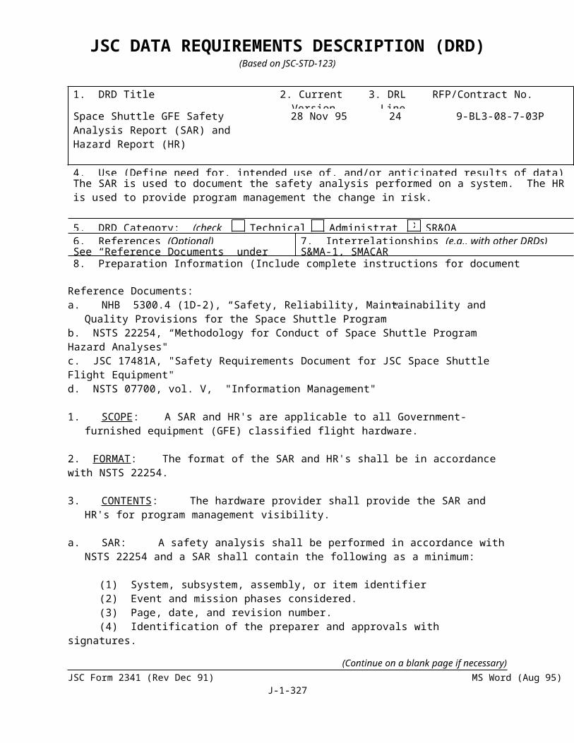
SECTION J
LIST OF ATTACHMENTSf. Provide a brief description of planned awards for the following quarter to SB/WO/SDB
plannedg. objective dollar award.
The SF294 shall be submitted semi-annually as described on the reverse of the form, and SF295 shall be submitted quarterly by the 30th day of the month following the close of the reporting period.
(Continue on a blank page if necessary)JSC Form 2341 (Rev Dec 91) (MS Word Aug 95) Page 327 of 1
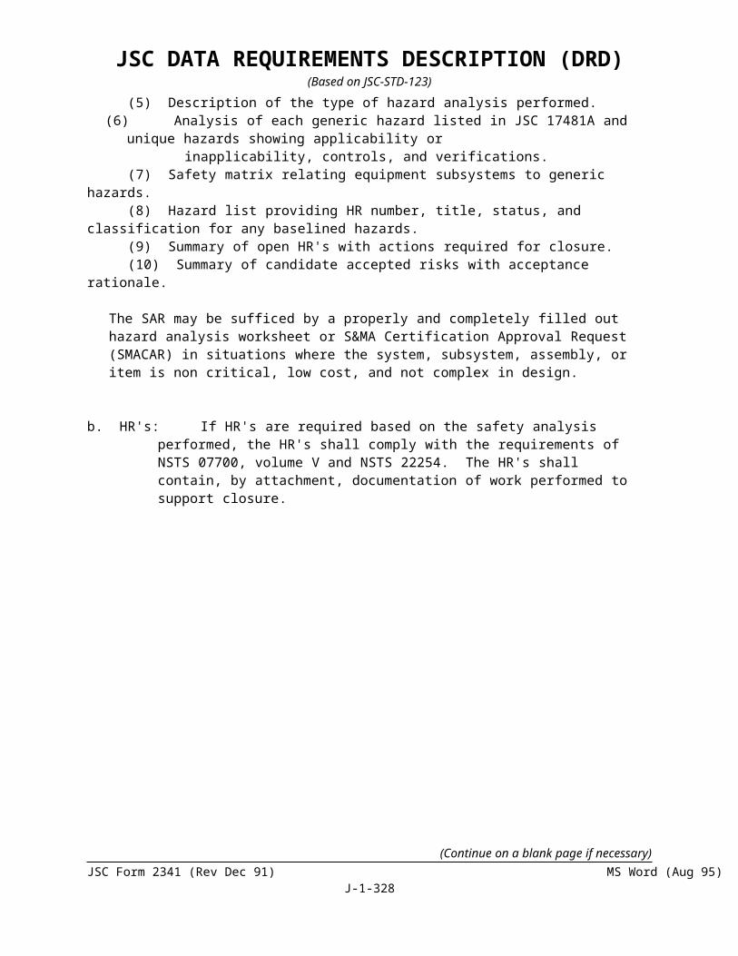
SECTION J
LIST OF ATTACHMENTS
1. DRD Title 2. Current Version Date
3. DRL Line
RFP/Contract No. (Procurement completes)
MATERIAL USAGE AGREEMENT (MUA) 1/27/97 56 9-BL3-08-03P
4. Use (Define need for, intended use of, and/or anticipated results of data)For NASA review and approval of all material usages and components which do not comply with contractual specification requirements.
5. DRD Category: (check one) Technical Administrative SR&QA6. References (Optional) 7. Interrelationships (e.g., with other DRDs) (Optional)See Block 8.8. Preparation Information (Include complete instructions for document preparation)
APPLICABLE DOCUMENTS:
SE-R-0006B, “General Specification NASA JSC Requirements for Materials and Processes.”
MSFC-SPEC-522A, “Design Criteria for Controlling Stress Corrosion Cracking.”
NHB 8060.1B, “Flammability, Odor, and Offgassing Requirements and Test Procedures for Materials in Environments That Support Combustion.”
SP-R-0022A, “General Specification Vacuum Stability Requirements of Polymeric Material for Spacecraft Application.”
JSC-09604/MSFC-HDBK-527, “Materials Selection List for Space Hardware Systems.”
PREPARATION INFORMATION:
1. SCOPE: This DRD establishes content, format, maintenance, and submittal requirements for MUA’s
2. CONTENTS: The MUA’s shall contain the information required by the NASA approved form (see JSC Form 1466, August 87) applicable block completed. The form shall be dated and submitted to ES5 with the program/project contract manager’s signature entered in the Program Manager block. Detailed treatment of the material application, color photographs, sketches, and rationale for usage acceptability shall be submitted to the extent and necessary for evaluation.
3. FORMAT: JSC Form 1466 (August 87) is the acceptable format for submittal of MUA data.
4. MAINTENANCE: The contractor shall maintain such files as necessary for tracking, reporting status, and traceability of submittals and responses for the MUA provided to NASA.
(Continue on a blank page if necessary)JSC Form 2341 (Rev Dec 91) (MS Word Aug 95) Page 328 of 1

SECTION J
LIST OF ATTACHMENTS
SECTION J-2
PROGRAM MANAGEMENT PLAN
TBD

SECTION J
LIST OF ATTACHMENTS
SECTION J-3
CONTRACT METRICS
Metric Standard
Cost Performance Contract Baseline
Failure Rates TBD
RDR Closure Time (Days) <180
LSS POS =>90
SSA POS =>80
HUT POS =>90
Change Proposal Metric (Days) <60
Subcontracting Goals 10% of Contract Value
Schedule Metrics
PDR IAW ContractBaseline
CDR IAW ContractBaseline
Certification Complete IAW ContractBaseline
Hardware Delivery IAW ContractBaseline
(Continue on a blank page if necessary)JSC Form 2341 (Rev Dec 91) (MS Word Aug 95) Page 330 of 1

SECTION J-4
PERFORMANCE EVALUATION (FEE) PLAN1.0 INTRODUCTION
In accordance with the provisions of NHB 5150.7E and FAR 16.404-2, an award fee evaluation procedure is hereby established for determination of award fees payable under this contract. The fee arrangement outlined in this plan has been established to motivate the contractor to strive for excellence in the quality and timeliness of work, safety, program provisioning, and subcontracting performance. All contract costs, with the exception of program provisioning, are subject to a separate cost incentive provision contained herein, and will not be evaluated as part of the award fee process.
The contractor ‘s performance will be evaluated to insure that activities performed under the contract are well balanced and that a high quality level of performance is consistently maintained. The payment of any award fee is contingent upon compliance with contractual requirements and successful performance as measured against the standards included in Appendix 1. The contractor may earn award fee from a minimum of zero dollars to a maximum stated in Clause B.3 of this contract. Any change in award fee provisions will be implemented via a bilateral modification, except for internal NASA processes and evaluation factors which are established unilaterally by NASA. Cost and fee adjustments to the contract will be reflected in Clause B.3.
Award Fee evaluations will be based upon subjective (qualitative) and objective (quantitative) analysis of the contractor’s performance for each evaluation period. Under the provisions of this plan, NASA may evaluate the contractor on any area of performance within the spectrum of the contract excluding costs determined under the separate incentive provisions. A significant element of any award fee evaluation shall be the contractor’s demonstrated performance in meeting or exceeding the SOW performance standards. Metrics have been established under the contract to support an objective assessment of the contractor’s performance (See Section J-3 Contract Metrics).
In addition to the award fee provision, this fee plan contains a separate cost incentive provision which will allow the contractor to earn additional fee should he underrun the contract cost baseline. Earned incentive fee will be based upon a cost sharing formula identified under Section 5.1 of this plan. It should be noted that this incentive provision does not apply to any costs associated with Government directed such as program provisioning. In addition, the incentive provision is subject to an award fee performance gate described under Section 5.2.
All fees payable throughout of the contract period of performance, including any negative fees, shall not exceed 15 percent of the estimated contract cost (less cost of money) or be less than zero.
All fees available for the current six month evaluation period are subject to Section 8.0 Fee Reduction for Catastrophic Loss.”
2.0 ORGANIZATIONAL STRUCTURE
The Performance Evaluation Board (PEB) will be established and approved by the Fee Determination Official (FDO) for the contract. The PEB will be comprised of NASA officials who are responsible for establishing specific evaluation criteria will assess the contractor’s performance related to the evaluation factors listed in Appendix 1. At the end of each six-month evaluation period (as identified in Attachment 2), the PEB will prepare a written report documenting its evaluation which shall include
(Continue on a blank page if necessary)JSC Form 2341 (Rev Dec 91) (MS Word Aug 95) Page 331 of 1
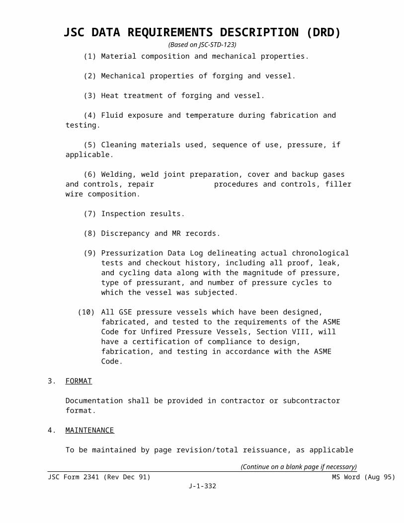
SECTION J-4
PERFORMANCE EVALUATION (FEE) PLANrecommendations for an adjective rating and numerical score to be assigned to the contractor’s performance during the evaluation period. This report as well as a PEB presentation will be provided to the FDO for his consideration.
The contractor may be given an opportunity to present information to the PEB prior to the PEB's making its fee recommendations to the FDO. The PEB shall consider the information submitted by the contractor and any other information available to the Board and shall submit its evaluation findings and recommendations to the FDO.
The contractor will be furnished a copy of the PEB's evaluation and conclusions and fee recommendation. The contractor shall be afforded an opportunity to submit for consid-eration of the FDO (a) proposed evaluations or conclusions; or (b) exceptions to the evaluations, conclusions, or fee recommendations of the PEB; and (c) supporting reasons for such exceptions or proposed evaluations or conclusions. The contractor’s submissions must be made in writing and must be submitted to the FDO within 10 calendar days from the date of contractor’s receipt of the PEB's findings and fee recommendation. The time for making such submissions may be extended at the discretion of the FDO.
After considering information submitted by the PEB, the PEB evaluations, conclusions, and fee recommendation; submissions to the FDO made by the contractor, if any; and other pertinent information available to the FDO, the FDO will make an award fee determination for the semiannual period covered by the PEB's fee recommendation. In the event the FDO has not received a submission from the contractor, the FDO will not make an award fee determination prior to the expiration of the 5-day period prescribed above for contractor submissions unless the contractor has affirmatively indicated, in writing, that no contractor submission will be made.
3.0 EVALUATION PROCEDURES
All 6-month performance evaluations will be interim pending a final determination at the end of the contract period of performance. A determination of the performance score and the related dollars earned for each evaluation period will be made by the FDO within 45 days after the end of the period. Procedures to be followed in monitoring, assessing, and evaluating contractor performance during each period, are described below.
No later than 45 calendar days prior to the start of each evaluation period, the contractor may submit to the Contracting Officer recommended areas of emphasis for the ensuing evaluation period that are within the general factors listed in Section 4.0 of this plan. Consideration will be given to the contractor’s recommendations; however, it is the Government’s responsibility to establish the specific areas of emphasis for each evaluation period.
No later than 15 days prior to the start of each new six-month evaluation period, the contractor will be notified by the Contracting Officer of the selected areas of emphasis for that period as well as any weightings NASA wishes to specify. Emphasis will be directed at particular areas under the contract which appear to the Government to be deserving of special attention and will be used in judging the contractor’s performance. These areas of emphasis may not cover the entire spectrum of performance that will be evaluated in determining award fee scores and dollars earned. Other pertinent factors included under the contract and general factors bearing upon overall performance will be considered.
(Continue on a blank page if necessary)JSC Form 2341 (Rev Dec 91) (MS Word Aug 95) Page 332 of 1

SECTION J-4
PERFORMANCE EVALUATION (FEE) PLANThe contractor shall receive a mid-point evaluation for each period and at other such times as is deemed appropriate to apprise the contractor of its performance assessment. These evaluations shall address specific areas where contractor performance requires improvement.
After the end of each evaluation period, the PEB shall meet to consider all the performance information it has obtained. At the meeting, the PEB will summarize its preliminary findings and recommendation in the Performance Evaluation Board Report (PEBR).
The contractor may furnish a self-evaluation report within 10 calendar days after the expiration of each evaluation period. This self-evaluation report shall not exceed 20 pages in length. The PEB will not submit its recommendation to the FDO until (1) the contractor’s self-evaluation report has been received and considered, or (2) the contractor has provided written notification that a self-evaluation report will not be submitted, or (3) the 10-day period provided for submission of the report has expired.
The PEB Chair is responsible for the preparation of the PEBR and will present the findings and recommendation to the FDO. The report will include an adjective rating and recommended overall performance and safety scores with supporting documentation. The contractor will be notified by the Contracting Officer of the PEB evaluation and recommended rating and score and will be provided a summary of the PEBR. The contractor may provide additional information for consideration by the FDO by notifying the Contracting Officer of its desire to do so. This is an opportunity for the contractor to provide any information which the contractor believes is relevant to its performance and which may affect the FDO’s determination. Any additional information should be provided to the Contracting Officer within 5 calendar days of contractor receipt of the PEB recommended rating and scores. This additional contractor information will be provided to the FDO by the Contracting Officer through the PEB Chair.
The FDO will consider the recommendation of the PEB, the PEBR, information provided by the contractor, if any, and any other pertinent information in determining the performance scores. The FDO’s determination of the scores will be stated in a written Award Fee Determination (AFD).
The Contracting Officer will issue a unilateral modification to recognize the award fee earned by the contractor in accordance with Appendix 1 which includes adjective ratings, as well as, a numerical scoring system from 0 - 100. Earned award fee dollars are calculated by applying the total numerical score to available dollars. Notwithstanding the preceding, the contractor will not earn award fee for any evaluation period when the performance score is “poor/unsatisfactory” (less than 61).
4.0 EVALUATION CRITERIA
Evaluation criteria against which the contractor’s performance will be evaluated are as follows:
QUALITY AND TIMELINESS OF WORK
SAFETY
PROGRAM PROVISIONING
(Continue on a blank page if necessary)JSC Form 2341 (Rev Dec 91) (MS Word Aug 95) Page 333 of 1

SECTION J-4
PERFORMANCE EVALUATION (FEE) PLANSMALL BUSINESS GOALS
Weightings for these evaluation criteria shall be identified in individual areas of emphasis letters provided to the contractor 15 days prior to the beginning of the applicable evaluation period. Reference Section 3.0
The contractor’s performance will be evaluated against the above criteria using the adjective ratings and definitions set forth in Appendix 1. The adjective rating for each evaluation criterion will be converted to a numerical grade. The award fee curve in Appendix 3. will be used to convert the numerical grade to the amount of award fee earned.
The above procedure will be followed for each evaluation period. The evaluation periods and the distribution of available maximum award fee are set forth in Appendix 2.
4.1 EVALUATION CRITERIA DEFINITIONS
a. Quality and Timeliness of Work
The contractor’s performance will be evaluated in the following areas: program management, engineering, design, development, test, analysis, AEA life extension activities, as well as, hardware repair, rework, and refurbishment. This includes an assessment of the contractor’s performance in the development, analysis and utilization of management data, total available resources, and program controls to effectively accomplish contract requirements. This will involve the assessment of contractor performance in planning, controlling, and managing Government property, as well as, contract and subcontract management.
The contractor will be evaluated against program schedules and key interim milestones, including non-recurring elements such as performance enhancements.In addition, the contractor will be assessed on the timely submittal and definitzation of change proposals, timely and accurate reporting of performance data; the processing of contract documentation deliverables, and the timely support of the NASA budget process.
b. Safety
Operational safety is of supreme importance to NASA. This includes flight safety issues involving the flight crew, potential risks to flight assets, and ground processing safety affecting personnel or facilities. Consideration will be given to the maintenance of process and product quality at all levels and assumes the implementation of performance measures as an indication of quality.
c. Program Provisioning
The contractor’s performance will be evaluated in the following areas: cost, field activities, special studies, special tests and supplier supportability and technology obsolescence as well as ISS and Shuttle Program interoperability support for international partners; manifesting, and scheduling issue resolution; international partner hardware and operational issues; EMU processing contractor issues; unscheduled EVA community meeting support; interface compatibility, and other unplanned EVA related activities as directed. The contractor’s response time to critical
(Continue on a blank page if necessary)JSC Form 2341 (Rev Dec 91) (MS Word Aug 95) Page 334 of 1
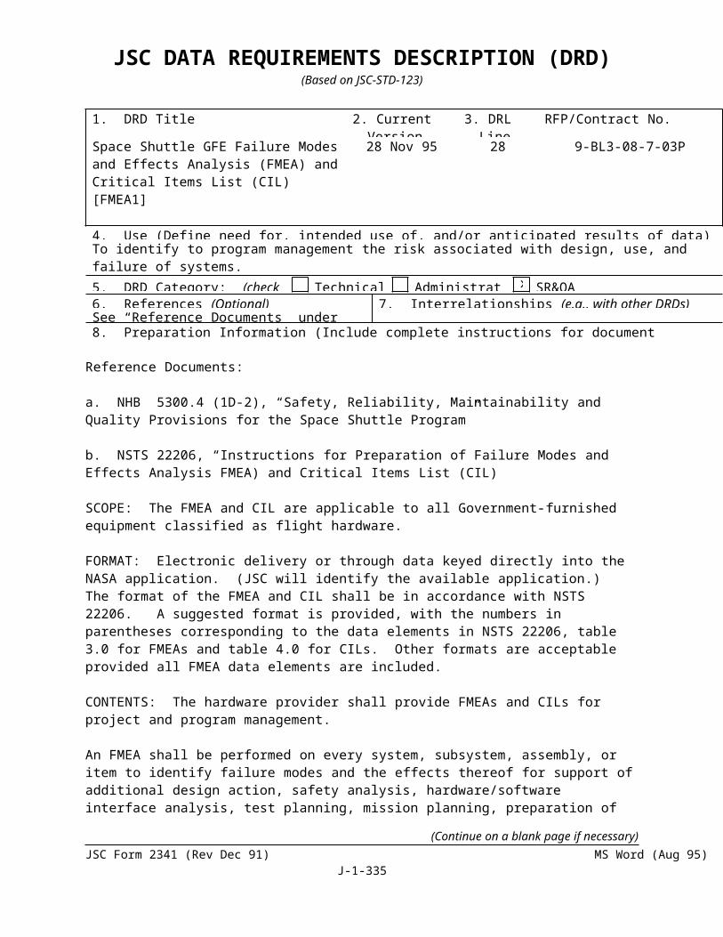
SECTION J-4
PERFORMANCE EVALUATION (FEE) PLANsituations will also be evaluated as well as the support of the annual program provisioning baseline negotiations.
d. Small Business Goals
The contractor will be evaluated on its efforts in achieving the contract subcontracting goals.
5.0 COST INCENTIVE FEE
A cost incentive fee is implemented under the contract to encourage effective contractor cost control. The contractor’s cost performance will be measured against the total contract target cost and will be payable in accordance with the provisions of FAR 52.216-10 --Incentive Fee.
If and when the contractor incurs any costs in any of the categories set forth in paragraph (e)(4) of referenced clause, the contractor shall notify the contracting officer of the amount of such cost together with such supporting detail as the contracting officer may reasonably require. Upon agreement or determination of the amount of such cost, Clause B.3 will be modified by the entry of a new line item titled, “Excluded Costs,” along with the amount of the cost determined or agreed to. This amount may be increased from time to time in the same manner. The total resulting amount will be included in the contract total estimated cost, but will not be included in the target cost, nor will it be considered in the determination of the Contractor’s incentive fee earning.
Costs associated with Government directed activities such as program provisioning, shall not be subject to the cost incentive feature of the contract. The contractor is required to account for such costs to support the computation of the earned incentive fee for each evaluation period.
The target cost for cost incentive fee purposes is found in Clause B.3. The maximum fee available on this contract is reflected in Clause B.3. There is no maximum cost incentive fee identified in Clause B.3 since the maximum cost incentive fee is flexible. The cost incentive fee at target is found in Clause B.3.
All fees payable under this contract, including any negative fees, shall not exceed 15
percent of the estimated contract cost (less cost of money) or be less than zero.
5.1 INCENTIVE SHARING ARRANGEMENT
The Contractor may share in cost overruns/underruns to target cost as follows:
a. Underrun to Target Cost
The Cost Incentive Fee payable under this contract shall be the target fee increased by $.30 cents for every dollar that total allowable cost subject to the incentive is less than target cost.
b. Overrun to Target Cost
(Continue on a blank page if necessary)JSC Form 2341 (Rev Dec 91) (MS Word Aug 95) Page 335 of 1

SECTION J-4
PERFORMANCE EVALUATION (FEE) PLANThe Cost Incentive Fee payable under this contract shall be the target fee decreased by $.30 cents for every dollar that the total allowable cost subject to the incentive is greater than the target cost.
5.2 AWARD FEE GATE
In order to qualify to earn a cost incentive fee in a given evaluation period, the Contractor must achieve an overall award fee score of at least 78 (SA 377). If the contractor has earned incentive fee for a period and has not received the minimum award fee score for that period, the amount of incentive fee that the contractor would have otherwise earned will be forfeited. Failure to qualify to receive a share of the underrun in a particular period does not prevent the Contractor from achieving a share of the projected underrun in other periods wherein the award fee gate is met.
5.3 PROVISIONAL PAYMENT OF COST INCENTIVE
Provisional cost incentive evaluations will be conducted in conjunction with the award fee evaluation periods indicated in Appendix 2. These evaluations will determine the amount of provisional cost incentive fee earned for the period based upon an underrun to the contract cost baseline. The basic tool to be used to determine the payment of provisional cost incentive fee based on underrun to target cost, or to reduce fees based on overruns to target cost, is contract earned value report. (Reference DRD No. 3)
In the event the Contractor does not meet an award fee gate indicated above for any evaluation period, the contractor shall forfeit all cost incentive fee for the period. If for any reason, the assessment by the Contacting Officer related to missed award fee gates identifies that the Contractor has been overpaid, the Contractor will repay the Government within 30 days.
Pending an interim determination of the amount of provisional cost incentive earned for a 6-month period, a portion of the available cost incentive fee for that period will be provisionally paid to the contractor on a monthly basis. For the first two evaluation periods, the portion paid will be 70 percent of the current period’s available amount. For all evaluation periods after the first two, the provisional payment will be based on an average of the two preceding periods. The provisional payment shall never exceed 80%. The amount of provisional fee which may be paid monthly in any evaluation period shall be prorated equally to the number of months in that period.
Should, at any time, the Contracting Officer determine that the contractor will not achieve a level of performance commensurate with the provisional rate, such rate may be reduced or discontinued.
The Contracting Officer shall notify the contractor, in writing, if it’s determined that a reduction or discontinuance is to be made.
5.4 TARGET FEE
The total target fee is delineated in Clause B.3.
6.0 AWARD FEE LOOK BACK PROVISION
(Continue on a blank page if necessary)JSC Form 2341 (Rev Dec 91) (MS Word Aug 95) Page 336 of 1

SECTION J-4
PERFORMANCE EVALUATION (FEE) PLANAll 6-month award fee determinations shall be provisional pending a final fee determination which will be made at contract completion. The final award fee determination will be based upon the contractor’s overall performance throughout the basic contract period of performance and any option period if exercised by the Government. At the conclusion of the last award fee period, the FDO shall assess the contractor’s overall performance under the contract in accordance with the award fee procedures contained herein. At the discretion of the FDO, the final determination may be based upon either an evaluation of individual periods or an overall assessment of the contractor’s performance.
The determination of the amount, if any, of any such adjustment shall be made on an assessment of the contractor’s total performance, as reflected in a final program audit, for the work covered by the contract period of performance. This assessment shall be based on the criteria set forth in paragraph 3.0. In the event the FDO, based upon information provided by the PEB and otherwise available, preliminarily determines that the contractor’s total performance warrants an adjustment, the contractor will be so notified and advised of the basis upon which such preliminary determination has been made. The contractor may, within 2 weeks after receiving such notification, provide the FDO any information considered relevant to the Total Performance Fee Determination. Any such information will be considered by the FDO, together with all other available, pertinent information, in making any adjustment as contemplated by this paragraph.
7.0 COST INCENTIVE DETERMINATION
All cost Incentive fee shall be provisional pending a final fee determination which will be made at contract completion. At the conclusion of the contract the contractor’s overall cost performance will be assessed in accordance with the cost incentive procedures contained herein. The amount of actual cost underrun, if any, will be allocated to each of the award fee periods based on the actual cost profile experienced by the contractor. If the contractor has met the award fee gate requirement for any period, he will earn the corresponding incentive fee based upon the share line indicated in section 5.1 above. If the contractor has not met the award fee gate for any award fee period and has experienced an underrun, he will forfeit any incentive fee that he would have otherwise have earned for that period. Failure to qualify to receive a share of the underrun In a particular period does not prevent the contractor from achieving a share of the projected underrun in other periods wherein the award fee gate is met.
In the event the parties are unable to agree on amounts to be so allocated, the Contracting Officer will determine the amounts.
8.0 FEE REDUCTION FOR CATASTROPHIC LOSS
All fees (award & incentive) available for a 6-month evaluation period are subject to a fee reduction assessed in the event of loss of life of a crew member when such loss is caused by the acts or omissions of the Contractor in performance of effort under this contract.
(Continue on a blank page if necessary)JSC Form 2341 (Rev Dec 91) (MS Word Aug 95) Page 337 of 1

SECTION J-4
PERFORMANCE EVALUATION (FEE) PLANAppendix 1
EVALUATION SCALE
ADJECTIVE RANGE OF RATING POINTS DESCRIPTION
Excellent 100 - 91 Of exceptional merit; exemplary performance in atimely, efficient manner; and economical manner, very minor (if any) deficiencies with no adverse effect on overall performance
Very Good 90 - 81 Very effective performance; fully responsive to contract requirements accomplished is a timely,efficient, and economical manner for the most part;only minor deficiencies.
Good 80 - 71 Effective performance; fully responsive to contract requirements; reportable deficiencies, but with little identifiable effect on overall performance.
Satisfactory 70 - 61 Meets or slightly exceeds minimum acceptablestandards; adequate results; reportable deficiencies with identifiable, but not substantial, effects on overall performance.
Poor/Unsatisfactory 60 - 0 Does not meet minimum acceptable standards in
one or more areas; remedial action required in oneor more areas; deficiencies in one or more areaswhich adversely affect performance.
(Continue on a blank page if necessary)JSC Form 2341 (Rev Dec 91) (MS Word Aug 95) Page 338 of 1

SECTION J-4
PERFORMANCE EVALUATION (FEE) PLAN Appendix 2Ref. SA 414
AWARD FEE EVALUATION PERIODS AND DISTRIBUTION
This Award Fee page jumps off of SA 413
(Continue on a blank page if necessary)JSC Form 2341 (Rev Dec 91) (MS Word Aug 95) Page 339 of 1
Date Program Non-Program Total Award FeePeriod Provisioning Provisioning Award Fee Earned
1 10/1/97-03/31/98 $553,016 $176,930 $729,946 $635,053 2 04/01/98-09/30/98 $440,684 $214,100 $654,784 $582,758 3 10/01/98-03/31/99 $483,419 $284,120 $767,539 $667,759 4 04/01/99-09/30/99 $723,902 $293,983 $1,017,885 $865,202 5 10/01/99-03/31/00 $655,370 $230,069 $885,439 $726,060 6 04/01/00-09/30/00 $580,880 $236,340 $817,220 $572,054 7 10/01/00-03/31/01 $583,411 $198,044 $781,455 $625,164 8 04/01/01-09/30/01 $536,699 $446,517 $983,216 $806,237 9 10/01/01-03/31/02 $735,270 $625,416 $1,360,686 $1,238,224
10 04/01/02-09/30/02 $687,732 $640,493 $1,328,225 11 10/01/02-03/31/03 $ - $595,905 $595,905 12 04/01/03-09/30/03 $ - $570,070 $570,070
Base Period Total $5,980,383 $4,511,987 $10,492,370
Option Period 313 10/01/03-03/31/04 $ - $451,247 $451,247 14 04/01/04-09/30/04 $ - $451,249 $451,249
Total $0 $902,496 $902,496
Total Award Fee $5,980,383 $5,414,483 $11,394,866

SECTION J-4
PERFORMANCE EVALUATION (FEE) PLAN
Appendix 3
AWARD FEE PERFORMANCE
POINTS ADJECTIVE GRADE RANGE % OF FEE
100 100.099 99.098 98.097 97.096 96.095 EXCELLENT 95.094 94.093 93.092 92.091 91.0
90 90.089 89.088 88.087 87.086 VERY GOOD 86.085 85.084 84.083 83.082 82.081 81.0
80 80.079 79.078 78.077 77.076 76.075 GOOD 75.074 74.073 73.072 72.071 71.0
70 70.069 69.068 68.067 67.066 66.065 SATISFACTORY 65.0
(Continue on a blank page if necessary)JSC Form 2341 (Rev Dec 91) (MS Word Aug 95) Page 340 of 1

SECTION J-4
PERFORMANCE EVALUATION (FEE) PLAN64 64.063 63.062 62.061 61.0
60 OR BELOW UNSATISFACTORY 0
(Continue on a blank page if necessary)JSC Form 2341 (Rev Dec 91) (MS Word Aug 95) Page 341 of 1

SECTION J-5
PROGRAM PROVISIONING WORK DESCRIPTIONS (PPWD)Ref. Mod. 11 Ref. SA 11 PPWD No. 98-01
TITLE EMU FIELD OPERATIONS
ESTIMATED COST $6,942,764DATE ISSUED October 1, 1997COMPLETION DATE September 30, 1998
WORK DESCRIPTION
I. PROGRAM MANAGEMENT FOR SHUTTLE EMU/EVA DEVELOPMENTALAND OUT OF FAMILY FIELD OPERATIONS
1. Manage EMU/EVA developmental/out-of-family field program.2. Maintain financial control and contract administration.3. Allocate resources based on program requirements.4. Establish and maintain task schedules.5. Manage and administer plans for travel, materials and other direct
costs.
II. EMU/EVA EQUIPMENT LOGISTICS/BONDED STORES/VAXSOFTWARE MAINTENANCE
1. Provide Bonded Stores transactions and Logistics for controlled EMU/EVA hardware and related equipment.
2. Maintain accountable property inventory control.3. Provide purchasing capability for purchases through GSA.4. Provide necessary VAX / Oracle Data Base maintenance required on a
periodic basis to update user screens, adjust data storage size allocations and provide software modifications to meet new requirements.
III. EMU DATA AND CONFIGURATION MANAGEMENT
1. Maintain Data Center records and prepare Test Readiness Review (TRR) packages for EMU/EVA development tests.
2. Maintain "Update and Distribution System" for CTSD EMU/EVA equipment Standard Procedures and drawings.
3. Maintain TPS, DR, DRL and drawing files.4. Maintain EMU flight configuration management system for CTSD assigned
EMU/EVA hardware.5. Process and track technical changes (CCBDs/ECOs), failure closures,
certifications/test plans and reports.6. Maintain flight hardware limited life item data and tracking, Yellow Tag
Notices (YTNs) and Service Instructions (SIs) for LSS and SSA CEIs assigned to CTSD.

SECTION J-5
PROGRAM PROVISIONING WORK DESCRIPTION (PPWD)7. Facilitate paper flow (RDRs, PDs, CCBDs, ECs) and problem resolutions
including CRM tasks.
IV. EMU AND RELATED EVA HARDWARE DEVELOPMENT
1. Incorporate ECs (Engineering Changes)into CTSD assigned EMU/EVA hardware.
2. Perform extended life testing and analysis.3. Perform EMU/EVA equipment certification testing.4. Generate and implement required DR dispositions on CTSD assigned EMU/
EVA hardware.5. Perform necessary CEI replacement, adjustment and retest.6. Provide engineering for EVA developmental activities at NASA NBL
facilities, on NASA zero G aircraft and at other facilities as directed by NASA.
7. Provide engineering for EMU engineering/test activities related to DTOs. 8. Perform other EMU/EVA development tasks as defined by the Subsystem
Manager.9. Identify space suit size requirements and verify assembly size.
10. Design, develop, fabricate and test developmental EMU/EVA related equipment.
11. Fabricate, test and checkout limited use developmental hardware for flight as related to EMU/EVA designs.
V. STS EMU MISSION MANAGERS
1. Provide day-to-day EMU and EMU related scheduling, coordination and technical oversight for the assigned STS mission(s). This includes oversight for technical changes (CCBDs/ECOs), failure closures, certifications, test plans and reports and support of FRR, V1103 testing and ETA vacuum runs.
2. Perform as single point of contact for all STS mission specific EMU/EVA issues between CTSD, the NASA Project Office, MOD, HS/WL Mission Point of Contact MPOC), ILC Dover, Boeing FEPC and other working partners.
3. Support Technical Program Reviews including the preparation of the EMU FRR presentation.
VI. ENVIRONMENTAL, HEALTH AND SAFETY (EH&S)
1. Maintain EH&S Plan2. Support the CTSD Facility Manager for EH&S issues.
VII. EMU AND EVA OUT-OF-FAMILY TECHNICAL OPERATIONS
1. Review proposed engineering changes for technical content and hardware/mission effectivity.
(Continue on a blank page if necessary)JSC Form 2341 (Rev Dec 91) (MS Word Aug 95) Page 343 of 1

SECTION J-5
PROGRAM PROVISIONING WORK DESCRIPTION (PPWD)2. Maintain effective communications between Field Sites, HS Windsor Locks,
ILC Dover and NASA JSC, and KSC. Provide interface coordination between Boeing FEPC, HS/WL, ILC, and CTSD on out-of-family tasks and problems.
3. Coordinate failure analysis activities between HS/WL, ILC-Dover and NASA, including preparation of field failure reports. Review FIAR/RDR corrective actions.
4. Review FEPC EMU Authorized Stowage List and Short EMU drawing for accuracy of configuration.
5. Coordinate preparation and review of CCBDs. Process RDRs, YTNs, EC/ECOs and program provisioning work descriptions.
6. Review and process WSTF test requests and MUAs.7. Provide expertise to Boeing FEPC when non-routine processing problems
are encountered (corporate memory, technical consultation).8. Initiate new processing requirements and procedures to implement failure
analysis corrective actions.9. Participate in the NASA Alerts review process and identify potential
impacts.10. Provide review input of NASA procedures, specifications as required.11. Provide assistance to NASA and prime contractors in resolving shuttle
vehicle interface (problems) and establishment of Interface Control Documents (ICDs).
12. Provide retrofit capability for all delivered hardware to the latest configuration. (At FEPC as directed).
13. Perform confidence testing of new and rebuilt flight hardware.14. Prepare and update flight hardware ground test procedures in accordance
with DRL 32 and 63.15. Attend meetings and provide technical expertise as directed by NASA.16. Provide technical review of new and changed BAO-FEPC test and
operation procedures.17. Review Boeing FEPC initiated performance related EMU DR dispositions.18. Coordinate maintenance of FEMU-R-001 per DRL 80.19. Provide status reports, performance evaluations and presentations on tasks
as directed by NASA. 20. Provide technical expertise for purchasing decisions and provide purchasing
capability for non-GSA purchases.21. Provide PAO presentations as directed by CTSD.22. Perform materials review prior to each vacuum chamber test.23. Perform other tasks as defined by the Subsystem Manager or COTR.24. Participate in the verification of EMU flight readiness for each mission
including support for the EMU FRR presentation and monitoring of KSC V1103 testing.
VIII. LABORATORY AND TEST EQUIPMENT MAINTENANCE
1. Maintain GSE configuration management system (CTSD).(Continue on a blank page if necessary)
JSC Form 2341 (Rev Dec 91) (MS Word Aug 95) Page 344 of 1

SECTION J-5
PROGRAM PROVISIONING WORK DESCRIPTION (PPWD)2. Review Boeing FEPC CCOs/ECMs for safety and upgrade
issues/incorporate changes as required.3. Perform EMU GSE maintenance, test, servicing, and calibration.4. Maintain CTSD EMU related labs and hardware.5. Update technician certification and maintain Cert data.6. Identify requirements for additional GSE and GSE spares as required.7. Fabricate and maintain test equipment as directed.8. Generate and update GSE documentation (drawings, FOMTS&Cs, hazard
analyses, non-metallic materials log sheets and special GSE procedures).9. Maintain Tool Crib for tools and expendables used for EMU/EVA
development and out of family problem resolutions.
IX. MISSION EVA OPERATIONS
1. Maintain a generic Mission Operations Plan and generate mission specific appendices which describe the real-time EVA mission related tasks, processes, and staffing information.
2. Provide real-time EVA mission related engineering and technical capabilities required to monitor EVA hardware performance and recommend corrective actions for anomalies or changes to the original mission plan.
3. Provide assistance to NASA and vehicle contractors for the preparation of flight checkout and flight maintenance procedures.
4. Maintain the CTSD EVA Operations Room.
X. SPACE SUIT ASSEMBLY SUBSYSTEM MANAGER
1. Provide day-to-day engineering and technical oversight/direction for the EMU SSA program.
2. Act as single point of contact for all SSA issues between NASA and plants and within NASA divisions.
3. Review/approve technical changes (CCBDs/ECOs), failure closures, certifications/test plans and reports.
4. Support Technical Program Reviews. XI. SPACE STATION EMU RELATED EVA DEVELOPMENT
1. Identify space suit size requirements and verify assembly size.2. Perform space suit component assembly, test, checkout for manned use,
and disassembly.3. Perform space suit repairs, maintenance and modifications.4. Provide manpower and expertise for EVA development activities at NASA
NBL facilities, on NASA zero G aircraft and at other JSC and remote facilities as directed by NASA.
5. Prepare test reports summarizing test result of activities.
(Continue on a blank page if necessary)JSC Form 2341 (Rev Dec 91) (MS Word Aug 95) Page 345 of 1

SECTION J-5
PROGRAM PROVISIONING WORK DESCRIPTION (PPWD)6. Provide technician manpower and expertise for the development,
maintenance, testing and evaluation of EVA equipment utilizing Space Shuttle Program designs and equipment.
XII. SPACE STATION EMU TECHNICAL COORDINATION
Provide technical coordination and support to identify and resolve issues relating to use of the EMU on Space Station. Tasks shall include the following:
1. Defining EMU provisioning guidelines (on orbit hardware quantities and stowage locations) required to support Space Station missions.
2. Ensuring compatibility and interoperability between the EMU and the Russian Orlan Space Suit, and the EMU related EVA Tools and Aids.
3. Identifying EMU to Space Station interfaces and EMU to Russian or EMU related EVA Tools and Aids interfaces, and support preparation of ICDs.
4. Defining requirements, procedures and support hardware (e.g., fixtures for dry-out of crew worn undergarments) for on orbit EMU maintenance, trouble-shooting and servicing, including microbial control.
5. Identifying new and revised ground processing requirements for EMU items for Space station.
6. Maintaining cognizance of Space Station schedule milestones so as to ensure that EMU hardware development, certification and production supports Space Station program needs.
7. Performing test planning, scheduling and coordination activities required to conduct system level certification and confidence tests of the EMU in support of Space Station
8. Performing test planning, scheduling and coordination activities required to conduct system level certification and confidence tests of the EMU in support of Space Station.
XIII. SPACE STATION EMU RELATED EVA DEVELOPMENT
1. Develop, fabricate, maintain, test and evaluate EMU related EVA hardware and EMU and ancillary equipment.
2. Process and deliver test ready EVA hardware for developmental activities at NASA NBL facilities, on NASA zero G aircraft and at other facilities as directed by CTSD.
3. Prepare test reports summarizing test results of activities. 4. Administer Bonded Stores/Logistics for non-EMU logistics tasks.
XIV. EMU RELATED EVA DEVELOPMENT
1. Provide engineering and technical support for in-house development, testing and evaluation of EVA hardware and related GSE and ancillary equipment.
2. Provide skilled manpower for the fabrication/sewing of extravehicular thermal crew protection development hardware.
(Continue on a blank page if necessary)JSC Form 2341 (Rev Dec 91) (MS Word Aug 95) Page 346 of 1

SECTION J-5
PROGRAM PROVISIONING WORK DESCRIPTION (PPWD)3. Purchase Enhanced SSA Hardware for CTSD as designated budget is
allocated.
XV. CREW ESCAPE EQUIPMENT EVA PRESSURE SUIT CONFIGURATION MANAGEMENT
1. Generate, update and maintain the CEE MACR.2. Generate CEE ACRs and maintain for CTSD hardware.3. Generate, process and track CEE Configuration Change Orders (CCOs).4. Process and track CEE CCBDs.5. Review CTSD TPSs for configuration impacts to CEE.6. Maintain computer data base and software for CEE configuration
applications.
XVI. EMU RELATED EVA DEVELOPMENT
1. Develop, fabricate, maintain, test and evaluate EVA hardware/equipmentand EMU and ancillary equipment.
2. Process and deliver test ready EVA hardware for developmental activities at NASA WETF facilities, on NASA zero G aircraft and at other facilities as directed by CTSD.
XVII. EMU RELATED EVA TOOLS DEVELOPMENT
1. Provide engineering for the development, fabrication, testing and certification of EMU related EVA tools and payload interface activity.
2. Coordinate preparation, review and NASA approvals of CCBDs for EMU related EVA Tools.
XVIII. EMU/EVA RELATED SOFTGOODS FABRICATION
1. Provide EMU/EVA softgoods for CTSD development, training and flighthardware as related to the EMU EVA activities.
XIX. ROBOTICS EVA EQUIPMENT LOGISTICS/BONDED STORES/VAX SOFTWARE MAINTENANCE
1. Provide Bonded Stores transactions and Logistics for controlled Robotics/EVA hardware and related equipment.
2. Provide necessary VAX / Oracle Data Base maintenance required on a periodic basis to update user screens, adjust data storage size allocations and provide software modifications to meet new requirements.
XX. EMU MISSION INTEGRATION
1. Conduct Technical Interchange Meetings with Russian counterparts.(Continue on a blank page if necessary)
JSC Form 2341 (Rev Dec 91) (MS Word Aug 95) Page 347 of 1

SECTION J-5
PROGRAM PROVISIONING WORK DESCRIPTION (PPWD)2. Maintain the EMU EVA design and verification requirements for STS-MIR experiments.3. Coordinate weekly Russian telecons and resolve EMU EVA related
technical problems.4. Define mission EMU EVA requirements to meet STS-MIR / ISS objectives.5. Define EMU hardware requirements for assigned missions.6. Develop EMU related EVA milestone schedule requirements in support of mission critical objectives.7. Conduct EMU EVA IPT meetings to comply with mission objectives.8. Present safety hazard analysis and flight readiness reviews to EVA CCB.
XXI. INTEROPERABLE HARDWARE
1. Determine need and feasibility of new or modified EMU interoperable hardware based on one suit per increment ISS crews.2. Define requirements for total inventory (including types, quantities,
and schedules) of EMU interoperable hardware to be produced for the ISS (Class I and III).
3. Perform EMU related fit checks in U.S. and Russia of OTA, UFR,MUT, Tool Carrier interfaces with Russian counterparts and hardware.
4. Interface directly with XA Integration and Operations office.5. Provide for one trip to Russia in support of EMU interoperable activities.
XXII. INTERFACE CONTROL DOCUMENTATION
1. Develop, update, and maintain EMU related ICDs between OTA, UFR, MUT, Tool Carrier and Russian hardware
XXIII. HARDWARE MISSION INTEGRATION
1. EMU flight requirements information exchange (attend/interface asnecessary with groups supporting CCR, CIR, FPSR, LSFR, DeltaLSFR, FM IPTs, POWGs, Flight Techniques, MICP).
2. EMU flight hardware information exchange (attend/interface asnecessary with groups supporting EMUB, EHB, EVA CCB, PRR, PDR,CDR, DCR, NBLs and other training events, SMART, PSRPs, OICB).
3. EMU flight hardware manifesting (attend/interface as necessary withgroups supporting mini-CEITs, CEITs, XA pre-bench review, FEPCbench review, EVA ORR, EVA FRR,EVA IPTs, EMU IPTs, MWGs,VMDB).
(Continue on a blank page if necessary)JSC Form 2341 (Rev Dec 91) (MS Word Aug 95) Page 348 of 1

SECTION J-5
PROGRAM PROVISIONING WORK DESCRIPTION (PPWD)4. EMU hardware availability evaluation, hardware stowage tracking and
coordination of pre-launch (mini-CEIT, CEIT, bench review) and post-launch (early vs. Standard destow) required shipments with CTSD,FEPC, KSC.
5. EMU technical order and MECSLSI review for accurate installation(attend/interface as necessary with groups supporting new PSA/TSAconfiguration fit checks and pull tests, DMICBs, USA CargoEngineering telecons).
6. EMU mission specific tools ESELs development, updating and maintenance.
7 ISS On-Orbit ESEL development, updating and maintenance.
8. Ensure manifested EMU related EVA hardware is on schedule to supportmilestone events (I.e., CEIT and Bench Review) as well as ensuring hardware is certified prior to shipment for flight (provide status to lead, EMU related EVA Hardware Development Group as required).
9. Fit Check Management.
a. Review test and verification requirements. b. Review hardware requirements including evaluation of hardware
availability. c. Review interface requirements. d. Develop, update and maintain flight specific fit check matrix. e. Coordinate pre-launch and post-launch hardware shipment.f. Coordinate approved fit check process (QA support, appropriate
documentation and tracking). g. Track and report failures and resolutions. h. Report status at EHB, EVA CCB, EVA AIT, OICB.
10. Maintain EMU related EVA Tool Logistics Database
a. FEPC/KSC Planning and Operations Meetings (Tuesdays). b. Perform periodic inventory to ensure configuration integrity.
11. Maintain EMU related EVA Tool Catalog
a. Develop/ Maintain/ Update configuration management process foron-line version.
b. Perform periodic inventory to ensure configuration integrity.
12. Generate / Process / Status CRs for the XA office (both I&O and Hardware groups)
(Continue on a blank page if necessary)JSC Form 2341 (Rev Dec 91) (MS Word Aug 95) Page 349 of 1

SECTION J-5
PROGRAM PROVISIONING WORK DESCRIPTION (PPWD) a. Internal EMU related EVA GFE CRs (prior to EHB CR process).b. Changes to PQDS, technical direction for manufacturing, cost increases, CARD changes, quantity changes, delivery date
changes, etc.
13. Coordinate with Boeing-Prime for changes to hardware deliverableto PGs.
14. Support hardware mission integration functions to assure accuratecompletion (i.e., ESELs, weight and volume of hardware).
15. Attend the EHB and CCB meetings for the XA Project Office.
a. Activities may include meeting minutes, agenda generation and distribution, scheduling, and general preparation for the aforementioned meetings.
16. XA Web construction, updates, and maintenance
17. Conduct two trips for fitcheck evaluations .
XXIV. INTEGRATE THE RUSSIAN SAFER (RSAFER) WITH THE RUSSIANORLAN SPACE SUIT FOR EVA
1. Weekly telecon/status support with EVA team members.2. Finalize Orlan DMA-HL integration at JSC.3. Support development of requirements and integration of the RSAFERwith the Orlan-M.4. Provide mock-up hardware required for Orlan-M engineering evaluations.5. Provide engineering coordination for EVA developmental activities at NASA NBL facilities, on NASA zero G aircraft and at other facilities for RSAFER
as directed by NASA.6. Provide support for fitchecks in U.S. and Russia of RSAFER interfaceswith Russian hardware7. Develop, review, redline, and obtain XA approval prior to obtainingRussian concurrence of the RSAFER Project Management Plan8. Develop, review, redline, and obtain XA approval prior to obtainingRussian concurrence of the RSAFER Project Technical Requirements
Specification.9. Develop, review, redline, and obtain XA approval prior to obtaining Russian concurrence of the RSAFER Prime Item Development Specifications10. Represent XA for Russian SAFER Project to review and coordinate FMEA/CIL, Hazard Reports, Certification Package (Operational Risk
(Continue on a blank page if necessary)JSC Form 2341 (Rev Dec 91) (MS Word Aug 95) Page 350 of 1

SECTION J-5
PROGRAM PROVISIONING WORK DESCRIPTION (PPWD) Assessment Executive Summary Report)11. Develop, review, redline, and obtain XA approval prior to obtaining Russian concurrence of the RSAFER Operations Manual12. Coordinate integration efforts of software and hardware of Russian SAFER Visual Reality lab for training purposes13. Coordinate development and certification of Orlan-M Interface Verification Tool for use in SAFER flight hardware fitchecks.
14. Provide for (2) trips and materials to support the aforementioned activities. Trips will be to Russia to support Technical Interchange meetings.15. Establish and maintain task schedules.16. Manage and plan this budget for travel, materials and other direct
costs.
PPWD No. 98-02
TITLE PREFLIGHT AND REAL-TIME MISSION SUPPORTESTIMATED COST $230,000DATE ISSUED October 1, 1997COMPLETION DATE September 30, 1998
WORK DESCRIPTION
The contractor will perform the following EVA preflight and real-time mission support activities:
1. Provide a mission point of contact at Hamilton Standard - Windsor Locks to interface with the field Mission Manager, participate in telecons, and interface with the field (HSMS, NASA, MOD, ILC) on mission specific issues before eachlaunch.
2. Research and answer action items associated with specific missions prior toFRR.
3. Prepare Hamilton Standard - Windsor Locks mission support coverage memo or GFY ’98 this includes 3 scheduled Shuttle EVA missions and 5 Shuttle missions without scheduled EVAs). This memo describes Shuttle launch and landing dates and times, dates and times of scheduled EVAs occurring (if applicable), and flight objectives to themission support staff and management.
4. Review and comment on field generated EVA Flight Readiness Review (FRR) presentation for each Shuttle flight (for GFY ’98 this includes 8 packages).
5. Provide real-time EVA support, including consumables (O2 usage(psi), battery
(Continue on a blank page if necessary)JSC Form 2341 (Rev Dec 91) (MS Word Aug 95) Page 351 of 1

SECTION J-5
PROGRAM PROVISIONING WORK DESCRIPTION (PPWD)amp. hours) used and CO2 removal capability left -BTUs(calculated from O2)),
monitoring, EMU analog from NASA and digital parameters, and answering real-time mechanical and electrical system action items from NASA (for GFY ’98 this includes 3 scheduled Shuttle EVA missions with 5 scheduled EVAs
6. Also included for GFY ’98 is one Flight Data System (FDS) upgrade to display additional parameters (Orbiter External Airlock Liquid Cooling Garment line temperature transducers, Metal Oxide starting CO2 capability-BTUs). No hardware or software architecture upgrades are included.
PPWD No. 98-03
TITLE SPECIAL STUDIES AND SPECIAL TESTING
ESTIMATED COST $1,975,000DATE ISSUED October 1, 1997COMPLETION DATE September 30, 1998
WORK DESCRIPTION
The contractor shall perform the following special studies and special testing activities:
1. Conduct evaluations, analyses and tests of proposed system changes for effects on safety, functionality, and/or cost effectiveness. Provide specialized information aiding in the utilization of the EMU under various conditions.
2. Fabricate prototype hardware to assist in analyses/evaluations.
3. Prepare and submit test plans to conduct special tests to NASA for approval.
4. Fabricate special fixtures/test set-ups to allow for completion of tests and conduct tests as defined by approved test plans.
5. Conducting tests as defined by approved test plans.
6. Analyze the results of special tests.
7. Prepare and submit reports (test reports, final reports) documenting resultsof analyses and/or evaluations.
8. Brief NASA on the results of analyses and/or evaluations.
9. Support/assist the completion of special tests performed at JSC with the EMUsystem, and equipment that interface with the EMU. Examples of equipment are
(Continue on a blank page if necessary)JSC Form 2341 (Rev Dec 91) (MS Word Aug 95) Page 352 of 1

SECTION J-5
PROGRAM PROVISIONING WORK DESCRIPTION (PPWD)the Phase VI Glove, Safer, and tools.
10. Support/conduct meetings where changes to the EMU system and/or interfaces to the EMU are being discussed/planned.
11. Prepare presentations of findings to support meetings at JSC where changes to the EMU are being discussed/planned.
12. Conduct evaluations and tests to assure EMU interoperability with the Russian Orlan suit and other Russian EVA related equipment.
13. Loads Evaluation
Provide definition of the maximum allowable hang weight in each stowage location of the vehicle upon incorporation of the Updated EMU Design Loads. Includes effort to finalize AAP and Planar HUT analyses based on the latest requirements received August 1, 1997 (reference EMU 7561, Direction for Shear Plate (I115) and AAP (I470) Structural Requirements Upon Incorporation of Updated EMU Design Loads).
a. Resolve factor of safety philosophy for multi-mission certification between Hamilton Standard and NASA.
b. Evaluate the EMU and AAP using the Updated EMU Design Loads as defined in EMU-7561, Direction for Shear Plate and AAP Structural requirements and cert criteria for Incorporation of Updated EMU Design Loads. Updated EMU Design Loads will be incorporated for STS-88, STS-90 and subsequent. STS-89 will use the same loads as were defined for STS-82 and are documented in EMU-7561. Hamilton Standard will provide the maximum allowable hang weight in each of the following stowage locations for launch and landing:
(1) External Airlock, Wall Mounted(2) Internal Airlock, Floor, Ceiling and Wall mounted(3) Middeck/No Airlock, Floor and Ceiling mounted
c. Evaluate the EMU and AAP against the EMU mission spectrum which is to be provided by NASA Structures. This evaluation will define the inspection intervals required on the EMU and AAP.
d. Deliverables: Deliver a contract letter to NASA for review and concurrence on the requirements. Additionally, Hamilton Standard will provide NASA with an engineering memorandum by March 2, 1998 defining the maximum allowable hang weight for each of the six stowage locations for launch and landing and recommended inspection intervals for the EMU and AAP.
14. Evaluation of AAP Latches and SCU Cams
(Continue on a blank page if necessary)JSC Form 2341 (Rev Dec 91) (MS Word Aug 95) Page 353 of 1

SECTION J-5
PROGRAM PROVISIONING WORK DESCRIPTION (PPWD)
Perform force tests on Airlock Adapter Plate latches (Reference RDR B-EMU-470-A001), and inspect and adjust the Service & Cooling Umbilical connector cams on the Shuttle Orbiters. The task includes perform the following:
a. Prepare documentation.
b. Inspect the axial play at the cam for the SCU Multiple Connector Latches and adjust them as necessary. Replace discrepant hardware as necessary. Also inspect and adjust as necessary the position of the Plunger Ball on the SCU Multiple Connector Latches.
c. Perform a latch handle force test on all Airlock Adapter Plates while applying a 20 lb axial load to the support pin.
d. Measure the clearance between the support pin and pin guide bushing "flats" to determine the present condition of the AAP Latches.
Due to Orbiter availability, it is expected that the above inspections will require two trips to KSC to complete. A Trip Report will be provided via an Engineering Memorandum.
15. EMU/Sprint AER CAM DTO Compatibility Test and Analysis
a. Review and analyze Sprint prototype RF data, test method, and instrumentation. Determine similarity of prototype equipment tested with Flight DTO equipment and adequacy of test. Compare results with EMU RF exposure limits.
b. Sprint RF compatibility test w/ EMU and/or evaluation in building 14.c. Issue Engineering Memorandum on findings and recommendations for STS-
87 mission.
16. Integration of a DTO Radiator into the EMU
Provide integration facilitation of the radiator. JSC will design and build the radiator, perform all testing and prepare all paper work necessary to fly the radiator. Support this task, which is in the pre CDR phase, by providing the following: a. Provide answers to system integration issues using analytical tools to verify
key parameters as required. Review the integration of the radiator with the EMU.
b. Review and approve CTSD’s certification plan. Agree what testing must be done to integrate the unit with the EMU i.e. Bench test to full scale to certification then SESL prior to flight. Review CTSD’s certification paperwork.
(Continue on a blank page if necessary)JSC Form 2341 (Rev Dec 91) (MS Word Aug 95) Page 354 of 1
SECTION J-5
PROGRAM PROVISIONING WORK DESCRIPTION (PPWD)It is assumed CTSD prepares all of the certification matrix closures. Review and approve CTSD’s certification report.
c. Continue to review candidate list of wetted materials/material coatings for DTO Radiator with respect to EMU compatibility. Identify any materials that are deemed incompatible and provide brief justification. Identify testing if necessary to insure sublimator compatibility with the selected materials in the radiator loop. Identify early on if Titanium is an acceptable material for this application.
d. Support a design review at JSC for the radiator.
e. Evaluate conditions to determine if any other EMU requirements will not be met with the radiator.
f. Review EMU (PLSS) Load capability and provide to NASA .
g. Provide a cognizant engineers (1) at HSMS and (1) at HSWL to support weekly telecons with CTSD . These engineers shall monitor and status progress of defined task actions.
h. HSMS to develop a plan to obtain a Multiple Connector . Write an RFS toBAO to obtain a DCM plug. CTSD will coordinate use of connector for this DTO. NASA is responsible for mating to multiple connector fittings withRadiator Umbilical, TMG, etc.
i. Draft memo notifying team of hose fitting interface so that appropriate length Titeflex hoses can be ordered in a timely manner. Use ISS EMU Umbilical TMG cover design for multiple connector if applicable.
j. Support
(1) 1-G fitchecks as necessary
(2) Thermal Vacuum Testing
(3) Related EMU interface issues such as the need for strain relief.
(4) Recommend optimum DTO radiator umbilical routing to 1) minimize chance of snagging and 2) yield least interference to crewman while maintaining position for ease of DCM mating.
17. Installation of SAAMD
Evaluate a suitable method of installation for use of the Stand Alone Acceleration Measurement Device (SAAMD) as follows:
(Continue on a blank page if necessary)JSC Form 2341 (Rev Dec 91) (MS Word Aug 95) Page 355 of 1

SECTION J-5
PROGRAM PROVISIONING WORK DESCRIPTION (PPWD)
a. Evaluate concepts for mounting SAAMD on the AAP and EMU. This task includes traveling to KSC to verify the vehicle configuration so that an appropriate available envelope could be defined for installing the SAAMD on the AAP.
b. Define final design concepts for SAAMD locations and drawings of the hardware.
c. HSMS to develop two sets of development hardware from detail drawings. A fitcheck of the hardware will be performed in Building 9 trainers at JSC
and the findings will be documented.
d. The design will be finalized based on fitcheck findings.
e. Deliverables: A memorandum will be delivered to NASA addressing the acceptability of flying the SAAMD. This memorandum will include the results of a fitcheck. Additionally, Hamilton Standard will provide two sets of development hardware to NASA
18. SSA Suit Sizing Document Analysis
a. Research of “as built” and “as measured” data on SSA components at ILC Dover.
b. Observe measurement of SSA components at BAO-FEPC in order to understand the differences between the ILC in-process restraint line measurements and BAO-FEPC pressurized component axial restraint line measurements.
c. Analyze the measurement data and submit a report detailing the findings and recommendations.
d. Revise the Enhanced Sizing Document to reflect the appropriate “as built” or “as measured” dimensions to produce a more “user friendly” document as required.
19. Evaluation of the CWR
Evaluate the use of the CWR with respect to sublimator performance. This includes the following:
a. 180-day water soak of the qualification CWR.b. Chemical analysis of the soak volumes.c. Sublimator testing on Rig 8 at HSSSI.d. Submittal of a final test report.
(Continue on a blank page if necessary)JSC Form 2341 (Rev Dec 91) (MS Word Aug 95) Page 356 of 1

SECTION J-5
PROGRAM PROVISIONING WORK DESCRIPTION (PPWD)
20. MMOD Risk Assessment & Mitigation
a. Maintenance of the MMOD management plan through 12/31/97.
b. Ttest programs to refine present understanding of EMU MMOD vulnerability.
(1) Recommend concepts, analyze concepts and assist in down-select process.
(2) Test definition and planning for penetration threshold refinement, andfor improved understanding of thresholds and criteria for “critical penetration.”
(3) Assist in text execution including real-time assessment of test results and provide input to test protocol modification as required.
(4) Data analysis including recommendation of specific areas for model refinement.
c. Prepare and publish Engineering Memorandums to correlate PNP/PNCP (old vs. New), supply inputs and recommendations based on Phase III hypervelocity impact testing and expansion of vulnerability definition to develop improved PNCP based on test results.
21. SPCE/EMU ICD
Support generation of an ICD to document the EMU-SPCE (Servicing, Performance, and Checkout Equipment) Interfaces. The ICD will consist of a drawing and an A-size specification. Upon completion of this effort, Hamilton Standard will deliver a released EMU/SPCE ICD to NASA.
22. SSA Glove Wrist Tether Loop Redesign
a. Define an upper strength limit for the glove wrist tether loop.b. Redesign the current wrist tether loop to meet the minimum and maximum
load requirementsc. Fabricate and testing of sample loops to verify the design meets all requirements.d. Preparation and submittal of a report identifying the new design and results of all testing including certification.f. Submittal of engineering documentation to incorporate the certified design.g. Provide a CCBD and recommendations to incorporate the new design for future flights.h. Redesign the tether strap to include the extended tether loop.
23. External Airlock-AAP Shear Plate & Planar HUT Model Verification
(Continue on a blank page if necessary)JSC Form 2341 (Rev Dec 91) (MS Word Aug 95) Page 357 of 1

SECTION J-5
PROGRAM PROVISIONING WORK DESCRIPTION (PPWD) Perform model verification testing on the AAP, Shear Plate and the Planar Hut
against the Performance Enhancements Loads.
a. Strain gage the AAP under the worst case load direction for the upper butt weld and the lower bend. The shear plate will be strained gaged and tested concurrently with the AAP to validate the test results obtained prior to STS-82.
b. As required, pull the AAP and shear plate until “permanent deformation” is apparent in the AAP and shear plate. Testing of the shear plate and AAP through permanent deformation will require two tests where each piece of hardware will be evaluated.
c. Perform a test on the Planar HUT to understand the load sharing between the two lower mounts of the PLSS/Planar HUT interface and the capability of the shell. As part of this effort, a stress coat and strain gage test will be performed. The worst case loading for the Planar HUT using the performance enhancement loads will be tested and will include a test up to the point where shell delamination occurs (or the design exceeds PEL requirements and no delamination occurs).
d. The following hardware will be used for these tests (the hardware below will be downgraded, as required, for this test series):
CRM Hardware:SOP Housing SV799044-1 s/n X5Y01SOP Housing Cover SV769988-3 s/n3261Tbonded Hardware: Shear Plate Adapters SV771957-1 & 957-2Spare Flight Shear Plate (inserts to be installed): SV771918-203 s/n 1 (The item will be downgraded for alternate use).
e. Upon completion, an Engineering Memorandum will be transmitted with final recommendations for the need for future design changes to the Shear Plate, AAP andPlanar HUT for a 310 pound EMU. Additionally, this information will be used to support the analyses of the maximum allowable hang weight in each of the EMU stowage locations.
24. EMU light Assembly Camera Assembly Harness
HSSSI and ILC Dover preparation for, attendance at, and follow-up for an ELCA Preliminary Requirements Review to be held at JSC on Thursday, October 9, 1997. HSSSI will send 1 Systems Engineer, 1 Electrical Design Engineer and 1 SSA Engineer. ILC Dover will send 1 Glove Engineer.
25. Reduced EMU Pre/Post Flight Ground Processing Effort
(Continue on a blank page if necessary)JSC Form 2341 (Rev Dec 91) (MS Word Aug 95) Page 358 of 1

SECTION J-5
PROGRAM PROVISIONING WORK DESCRIPTION (PPWD)Conduct phase 2 effort on redefining the EMU pre/post flight ground processing. Continue effort towards implementation for STS-91 with priority on the SEMU. Phase 2 will conclude with a presentation at JSC of the proposed document changes and a recommendation on STS-91 implementation and definition of any necessary actions for STS-91. The meeting is targeted to be conducted the week of January 5, 1998. Specific activity under this phase shall be:
a. Continue review and assessment of Criticality 1/1, 2/1R, 2/2 & 3/1R FMEAs, CILs, HRs, and previous RDRs
b. Draft of revised FEMU-R-001 reflecting new proposed process with logic flow chart *
c. Provide definition of revisions necessary to the existing FMEA, CIL, and HR documentation *
d. Review (and mark for change) Boeing FEPC hardware change out test matrix based on new process *
e. Assist Boeing FEPC in draft of test procedures (if required beyond the FEMU -R-001 definitions) *
f. Document meeting minutes, actions, and recommendations. Output will consist of:
(1) Draft of revisions for the following documents, FEMU-R-001, FMEA, CIL, HR
(2) Impact matrix against failure modes(3) An Engineering Memorandum summarizing this activity.
* Documentation for review by all approval organizations to support STS-91 effectivity CCBD.
26. Hand Molds for Phase VI Glove Candidates
As directed, obtain hand molds for use in building Phase VI Gloves for flights STS-92 (3A), STS-97 (4A), and STS-99 (6A). Three crew members have been identified on these three flights as requiring Phase VI Gloves. This task will consist of the following activities.
a. Travel for 2 ILC personnel to JSC for 1 week to obtain hand molds.b. Hand Mold Material Kit procurement. (enough for 12 pairs of hand molds)c. Processing effort necessary to prepare molds for use in Phase VI glove
builds.
(Continue on a blank page if necessary)JSC Form 2341 (Rev Dec 91) (MS Word Aug 95) Page 359 of 1

SECTION J-5
PROGRAM PROVISIONING WORK DESCRIPTION (PPWD)At the completion of this effort, 12 pairs of hand molds and 12 pairs of hand reproductions are to be retained at ILC-Dover for use in building Phase VI gloves. Also, an Engineering Memorandum will be generated comparing the actual data to the number of custom size Phase VI gloves necessary.
PPWD No. 98-04
TITLE EVA SUPPLIER SUPPORTABILITY AND TECHNOLOGY OBSOLESCENCE
ESTIMATED COST $2,552,236DATE ISSUED October 1, 1997COMPLETION DATE September 30, 1998
WORK DESCRIPTION
The contractor shall complete the following supplier supportability and technology obsolescence activities:
1. Research EMU material requirements and identify replacement materials.
2. Contact suppliers and/or other contractors for recommendation replacement materials or processes.
3. Obtain samples of replacement material candidates.
4. Prepare certification test plans, procedures, and reports as required.
5. Prepare samples and associated tooling / fixtures to support sample evaluation
6. Perform certification testing and/or testing to support certification by analysis, including the reduction and comparison of data to both requirements and previously certified materials/ components.
7. Perform process development testing as it relates to the implementation of aqueous-based precision cleaning technologies and item-specific compatibility testing.
8. Document changes including specifications, drawings, Limited Life List, FMECA (Failure Modes Effects and Criticality Analysis), Contamination Control Plan, Operation Sheets, Vendor Baselines, Parts Lists, CCBDs, and Engineering Changes.
9. Research industry for potential replacements for obsolete technologies, preparing documentation packages/ Requests for Information (RFI) and evaluation of responses for adequacy as replacement technologies/suppliers.
(Continue on a blank page if necessary)JSC Form 2341 (Rev Dec 91) (MS Word Aug 95) Page 360 of 1

SECTION J-5
PROGRAM PROVISIONING WORK DESCRIPTION (PPWD)10. Prepare of Requests for Quotation (RFQ), evaluation of respondents’ proposals
including technical evaluation and negotiations and placement of purchase orders.
11. Redesign activity as required to establish replacement technologies for those that have been determined to be obsolete. Oversight/ approval of Preliminary Design Reviews (PDR) and Critical Design Reviews (CDR) by selected suppliers of replacement technologies.
12. Fabricate and test development hardware and certify requirements associated with new technologies.
13. Evaluate the effect of changes to the following material changes on LSS hardware:
a. Braycote 601 manufacturing process has been modified and material is now labeled as Braycote 601 EF (Environmentally Friendly). It is used with the Item 115. Evaluate changes in Braycote 601 manufacturing process. Output: Analysis Report to NASA/XA.
b. CCC O-Ring compounds (L0737-60 and L0946-60) no longer available from Parker. Obtain cured sheet stock of new compound (L1223-60) for WSTF and HSD Materials Engineering testing. Output: WSTF test result and report to NASA/XA evaluating acceptability of new compound for EMU use and stating rationale.
c. Krytox AC240 manufacturing process has been modified to eliminate the use of ozone depleting compounds (ODC’s). It is used with the Item 137.
Output: Analysis Report to NASA/XA.
Ref. SA 87PPWD No. 99-01
TITLE EMU FIELD OPERATIONS
WORK DESCRIPTION
The contractor shall perform the following EMU field activities:
A. PROGRAM MANAGEMENT FOR SHUTTLE EMU/EVA DEVELOPMENTALAND OUT OF FAMILY FIELD OPERATIONS
1. Manage EMU/EVA developmental/out-of-family field program.2. Maintain financial control and contract administration.3. Allocate resources based on program requirements.4. Establish and maintain task schedules.5. Manage and administer plans for travel, materials and other direct
(Continue on a blank page if necessary)JSC Form 2341 (Rev Dec 91) (MS Word Aug 95) Page 361 of 1

SECTION J-5
PROGRAM PROVISIONING WORK DESCRIPTION (PPWD)costs.
6. Provide monthly Estimate-at-Completion report.
B. EMU/EVA EQUIPMENT LOGISTICS/BONDED STORES
1. Provide Bonded Stores transactions and Logistics for controlled EMU/EVA hardware and related equipment.
2. Maintain accountable property inventory control.3. Provide purchasing capability for purchases through GSA.4. The contractor shall secure applicable I/T plan numbers and CO approval before
any I/T related work is initiated including VAX / Oracle maintenance, and/or hardware or software updates and modifications.
C. EMU DATA AND CONFIGURATION MANAGEMENT
1. Maintain Data Center records and prepare Test Readiness Review (TRR) packages for EMU/EVA development tests.
2. Maintain "Update and Distribution System" for CTSD EMU/EVA equipment Standard Procedures and drawings.
3. Maintain TPS, DR, DRL and drawing files.4. Maintain EMU flight configuration management system for CTSD assigned
EMU/EVA hardware.5. Process and track technical changes (CCBDs/ECOs), failure closures,
certifications/test plans and reports.6. Maintain flight hardware limited life item data and tracking, Yellow Tag Notices
(YTNs) and Service Instructions (SIs) for LSS and SSA CEIs assigned to CTSD.7. Facilitate paper flow (RDRs, PDs, CCBDs, ECs) and problem resolutions including
CRM activities.
D. EMU AND RELATED EVA HARDWARE DEVELOPMENT
1. Incorporate ECs (Engineering Changes)into CTSD assigned EMU/EVA hardware.2. Perform extended life testing and analysis.3. Perform EMU/EVA equipment certification testing.4. Generate and implement required DR dispositions on CTSD assigned EMU/ EVA
hardware.5. Perform necessary CEI replacement, adjustment and retest.6. Provide engineering for EMU EVA developmental activities at NASA NBL facilities,
on NASA zero G aircraft and at other facilities as directed by NASA.7. Identify space suit size requirements and verify assembly size.8. Design, develop, fabricate and test developmental EMU/EVA related
equipment. 9. Provide engineering and technical support for in-house development, testing and
evaluation of EMU EVA hardware and related GSE and ancillary equipment. 10. Provide skilled manpower for the fabrication/sewing of extravehicular thermal crew
protection development hardware.11. Evaluate, test, human-rate and certify for flight newly developed/revised EMU and
related equipment.
(Continue on a blank page if necessary)JSC Form 2341 (Rev Dec 91) (MS Word Aug 95) Page 362 of 1

SECTION J-5
PROGRAM PROVISIONING WORK DESCRIPTION (PPWD)12. Perform the fabrication/sewing of enhanced extravehicular thermal crew protection
development hardware related to the EMU.
E. STS EMU MISSION MANAGERS
1. Provide day-to-day EMU and EMU related scheduling, coordination and technical oversight for the assigned STS mission(s). This includes oversight for technical changes (CCBDs/ECOs), failure closures, certifications, test plans and reports and support of FRR, V1103 testing and ETA vacuum runs.
2. Perform as single point of contact for all STS mission specific EMU/EVA issues between CTSD, the NASA Project Office, MOD, HS/WL Mission Point of Contact MPOC), ILC Dover, USA FCE and other working partners.
3. Generate and maintain EMU Standard Equipment Lists (ESELs), generate and maintain the Mission Manager Matrix and track flight hardware contractual mission specific delivery dates.
4. Support Technical Program Reviews including the preparation of the EMU FRR presentation.
F. ENVIRONMENTAL, HEALTH AND SAFETY (EH&S)
1. Maintain EH&S Plan2. Support the CTSD Facility Manager for EH&S issues.
G. EMU AND EVA OUT-OF-FAMILY TECHNICAL OPERATIONS
1. Review proposed engineering changes for technical content and hardware/mission effectivity.
2. Maintain effective communications between Field Sites, HS Windsor Locks, ILC Dover and NASA JSC, and KSC. Provide interface coordination between USA FCEFEPC, HS/WL, ILC, and CTSD on out-of-family tasks and problems.
3. Coordinate failure analysis activities between HS/WL, ILC-Dover and NASA, including preparation of field failure reports. Review FIAR/RDR corrective actions.
4. Coordinate preparation and review of CCBDs. Process RDRs, YTNs, EC/ECOs and program provisioning work descriptions.
5. Review and process WSTF test requests and MUAs.6. Provide expertise to USA FCE when non-routine processing problems are
encountered (corporate memory, technical consultation).7. Initiate new processing requirements and procedures to implement failure
analysis corrective actions.8. Participate in the NASA Alerts review process and identify potential impacts.
9. Provide review input of NASA procedures, specifications as required.10. Provide assistance to NASA and prime contractors in resolving shuttle vehicle
interface (problems) and establishment of Interface Control Documents (ICDs).11. Provide retrofit capability for all delivered hardware to the latest configuration. (At
FEPC as directed).12. Perform confidence testing of new and rebuilt flight hardware.13. Prepare and update flight hardware ground test procedures in accordance with
DRL 32 and 63.
(Continue on a blank page if necessary)JSC Form 2341 (Rev Dec 91) (MS Word Aug 95) Page 363 of 1

SECTION J-5
PROGRAM PROVISIONING WORK DESCRIPTION (PPWD)14. Attend meetings and provide technical expertise as directed by NASA.15. Provide technical review of new and changed BAO-FEPC test and operation
procedures.16. Review USA FCE initiated performance related EMU DR dispositions.17. Coordinate maintenance of FEMU-R-001 per DRL 80.18. Provide status reports, performance evaluations and presentations on tasks as
directed by NASA. 19. Provide technical expertise for purchasing decisions and provide purchasing
capability for non-GSA purchases.20. Provide PAO presentations as directed by CTSD.21. Perform materials review prior to each vacuum chamber test.22. Participate in the verification of EMU flight readiness for each mission including
support for the EMU FRR presentation and monitoring of KSC V1103 testing.
H. EMU LABORATORY AND TEST EQUIPMENT MAINTENANCE
1. Maintain GSE configuration management system (CTSD).2. Review USA FCE CCOs/ECMs for safety and upgrade issues/incorporate changes
as required.3. Perform EMU GSE maintenance, test, servicing, and calibration.4. Maintain CTSD EMU related labs and hardware.5. Update technician certification and maintain Cert data.6. Identify requirements for additional GSE and GSE spares as required.7. Fabricate and maintain test equipment as directed.8. Generate and update GSE documentation (drawings, Familiarization Operation
and Maintenance, Test, Service & Calibration (FOMTS&C), hazard analyses, non-metallic materials log sheets and special GSE procedures).
9. Maintain Tool Crib for tools and expendables used for EMU/EVA development and out of family problem resolutions.
10. Maintain technician certification and training.
I. EMU MISSION EVA OPERATIONS
1. Maintain a generic Mission Operations Plan and generate mission specific appendices which describe the real-time EVA mission related tasks, processes, and staffing information.
2. Provide real-time EVA mission related engineering and technical capabilities required to monitor EVA hardware performance and recommend corrective actions for anomalies or changes to the original mission plan.
3. Provide assistance to NASA and vehicle contractors for the preparation of flight checkout and flight maintenance procedures.
4. Maintain the CTSD EVA Operations Room.
J. EMU SPACE SUIT ASSEMBLY SUBSYSTEM MANAGER
1. Provide day-to-day engineering and technical oversight/direction for the EMU SSA program.
2. Act as single point of contact for all SSA issues between NASA and plants and within NASA divisions.
(Continue on a blank page if necessary)JSC Form 2341 (Rev Dec 91) (MS Word Aug 95) Page 364 of 1

SECTION J-5
PROGRAM PROVISIONING WORK DESCRIPTION (PPWD)3. Review/approve technical changes (CCBDs/ECOs), failure closures,
certifications/test plans and reports.4. Support Technical Program Reviews.
K. EMU LIFE SUPPORT SYSTEM SUBSYSTEM MANAGER
1. Provide day-to-day engineering and technical oversight/direction for the EMU LSS program.
2. Act as single point of contact for all LSS issues between NASA and plants and within NASA divisions.
3. Review/approve technical changes (CCBDs/ECOs), failure closures, certifications/test plans and reports.
4. Support Technical Program Reviews.
L. EMU RELATED EVA DEVELOPMENT - SPACE STATION
1. Identify space suit size requirements and verify assembly size.2. Perform space suit component assembly, test, checkout for manned use, and
disassembly.3. Perform space suit repairs, maintenance and modifications.4. Provide manpower and expertise for EMU EVA development activities at NASA
NBL facilities, on NASA zero G aircraft and at other JSC and remote facilities as directed by NASA.
5. Prepare test reports summarizing test result of activities.6. Provide technician manpower and expertise for the development, maintenance,
testing and evaluation of EMU EVA equipment utilizing Space Shuttle Program designs and equipment.
7. Develop, fabricate, maintain, test and evaluate EMU related EVA hardware and EMU and ancillary equipment.
8. Process and deliver test ready EVA hardware for developmental activities at NASA NBL facilities, on NASA zero G aircraft and at other facilities as directed by CTSD.
9. Prepare test reports summarizing test results of activities. 10. Administer Bonded Stores/Logistics for logistics tasks.
M. EMU TECHNICAL COORDINATION
Provide technical coordination and support to identify and resolve issues relating to use of the EMU on Space Station. Tasks shall include the following:
1. Defining EMU provisioning guidelines (on orbit hardware quantities and stowage locations) required to support Space Station missions.
2. Ensuring compatibility and interoperability between the EMU and the Russian Orlan Space Suit, and the EMU related EVA Tools and Aids.
3. Identifying EMU to Space Station interfaces and EMU to Russian or EMU related EVA Tools and Aids interfaces, and support preparation of ICDs.
4. Defining requirements, procedures and support hardware (e.g., fixtures for dry-out of crew worn undergarments) for on orbit EMU maintenance, trouble-shooting and servicing, including microbial control.
(Continue on a blank page if necessary)JSC Form 2341 (Rev Dec 91) (MS Word Aug 95) Page 365 of 1
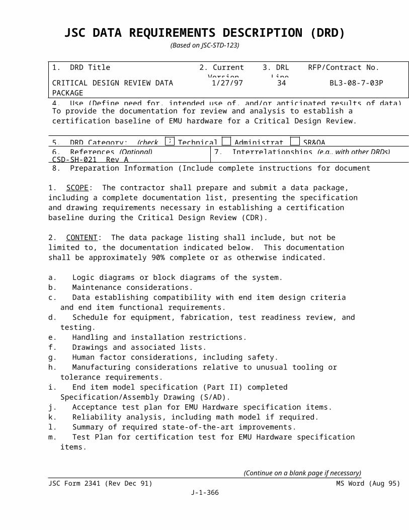
SECTION J-5
PROGRAM PROVISIONING WORK DESCRIPTION (PPWD)5. Identifying new and revised ground processing requirements for EMU items for
Space station.6. Maintaining cognizance of Space Station schedule milestones so as to ensure
that EMU hardware development, certification and production supports Space Station program needs.
7. Performing test planning, scheduling and coordination activities required to conduct system level certification and confidence tests of the EMU in support of Space Station
O. EMU RELATED EVA DEVELOPMENT
1. Develop, fabricate, maintain, test and evaluate EVA hardware/equipment and EMU and ancillary equipment.
2. Process and deliver test ready EVA hardware for developmental activities at NASA WETF facilities, on NASA zero G aircraft, and at other facilities as directed by CTSD.
P. EMU RELATED EVA TOOLS DEVELOPMENT
1. Provide engineering for the development, fabrication, testing and certification of EMU related EVA tools and payload interface activity.
2. Coordinate preparation, review and NASA approvals of CCBDs for EMU related EVA Tools.
Q. EMU/EVA RELATED SOFTGOODS FABRICATION
1. Provide EMU/EVA softgoods for CTSD development, training and flighthardware as related to the EMU EVA activities.
PPWD No. 99-02
TITLE PREFLIGHT AND REAL-TIME MISSION SUPPORT
WORK DESCRIPTION
The contractor shall perform the following EMU EVA preflight and real-time mission activities:
1. Provide a mission point of contact at Hamilton Standard - Windsor Locks to interface with the field Mission Manager, participate in telecons, and interface with the field (HSMS, NASA, MOD, ILC) on mission specific issues before eachlaunch.
2. Research and answer action items associated with specific missions prior toFRR.
3. Prepare HSSSI - Windsor Locks mission support coverage memo for GFY ’99, this includes 4 scheduled Shuttle EVA missions and 3 Shuttle missions without scheduled EVAs). This memo describes Shuttle launch and landing dates and times, dates and
(Continue on a blank page if necessary)JSC Form 2341 (Rev Dec 91) (MS Word Aug 95) Page 366 of 1

SECTION J-5
PROGRAM PROVISIONING WORK DESCRIPTION (PPWD)times of scheduled EVAs occurring (if applicable), and flight objectives to the mission support staff and management.
4. Review and comment on field generated EVA Flight Readiness Review (FRR) presentation for each Shuttle flight (for GFY ’99 this includes 7 packages).
5. Provide real-time EVA support, including consumables (O2 usage(psi), battery
amp. hours) used and CO2 removal capability left -BTUs(calculated from O2)),
monitoring, EMU analog from NASA and digital parameters, and answering real-time mechanical and electrical system action items from NASA (for GFY ’98 this includes 3 scheduled Shuttle EVA missions with 5 scheduled EVAs
6. Provide Flight Data System (FDS) upgrade to display additional parameters (Orbiter External Airlock Liquid Cooling Garment line temperature transducers, Metal Oxide starting CO2 capability-BTUs). This upgrade is a change from a Macintosh based operating system with LabView to a PC based operating system with LabView only. No hardware or software architecture upgrades are included. The contractor shall secure applicable I/T plan numbers and CO approval before work is initiated on the Flight Data System upgrade.
PPWD No. 99-03
TITLE SPECIAL STUDIES AND SPECIAL TESTING
WORK DESCRIPTION
The contractor shall perform the following special studies and special testing activities:
1. Conduct evaluations, analyses and tests of proposed system changes for effects on safety, functionality, and/or cost effectiveness. Provide specialized information aiding in the utilization of the EMU under various conditions.
2. Fabricate prototype hardware to assist in analyses/evaluations.
3. Prepare and submit test plans to conduct special tests to NASA for approval.
4. Fabricate special fixtures/test set-ups to allow for completion of tests and conduct tests as defined by approved test plans.
5. Conducting tests as defined by approved test plans.
6. Analyze the results of special tests.
7. Prepare and submit reports (test reports, final reports) documenting results of analyses and/or evaluations.
8. Brief NASA on the results of analyses and/or evaluations.
(Continue on a blank page if necessary)JSC Form 2341 (Rev Dec 91) (MS Word Aug 95) Page 367 of 1

SECTION J-5
PROGRAM PROVISIONING WORK DESCRIPTION (PPWD)9. Support/assist the completion of special tests performed at JSC with the EMU
system, and equipment that interface with the EMU.
10. Support/conduct meetings where changes to the EMU system and/or interfaces to the EMU are being discussed/planned.
11. Prepare presentations of findings to support meetings at JSC where changes to the EMU are being discussed/planned.
12. Conduct evaluations and tests to assure EMU interoperability with the Russian Orlan suit and other Russian EVA related equipment.
PPWD No. 99-04
TITLE EVA SUPPLIER SUPPORTABILITY AND TECHNOLOGY OBSOLESCENCE
WORK DESCRIPTION
The contractor shall complete the following supplier supportability and technology obsolescence activities:
1. Research EMU material requirements and identify replacement materials.
2. Contact suppliers and/or other contractors for recommendation replacement materials or processes.
3. Obtain samples of replacement material candidates.
4. Prepare certification test plans, procedures, and reports as required.
5. Prepare samples and associated tooling / fixtures to support sample evaluation.
6. Perform certification testing and/or testing to support certification by analysis, including the reduction and comparison of data to both requirements and previously certified materials/ components.
7. Perform process development testing as it relates to the implementation of aqueous-based precision cleaning technologies and item-specific compatibility testing.
8. Document changes including specifications, drawings, Limited Life List, FMECA (Failure Modes Effects and Criticality Analysis), Contamination Control Plan, Operation Sheets, Vendor Baselines, Parts Lists, CCBDs, and Engineering Changes.
9. Research industry for potential replacements for obsolete technologies, preparing documentation packages/ Requests for Information (RFI) and evaluation of responses for adequacy as replacement technologies/suppliers.
(Continue on a blank page if necessary)JSC Form 2341 (Rev Dec 91) (MS Word Aug 95) Page 368 of 1

SECTION J-5
PROGRAM PROVISIONING WORK DESCRIPTION (PPWD)10. Prepare of Requests for Quotation (RFQ), evaluation of respondents’ proposals
including technical evaluation and negotiations and placement of purchase orders.
11. Redesign activity as required to establish replacement technologies for those that have been determined to be obsolete. Oversight/ approval of Preliminary Design Reviews (PDR) and Critical Design Reviews (CDR) by selected suppliers of replacement technologies.
12. Fabricate and test development hardware and certify requirements associated with new technologies.
PPWD No. 99-05
TITLE ORLAN EXPERTISE
WORK DESCRIPTION
The contractor shall perform the followings Orlan expertise activities:
1. Develop Orlan technical expertise required to support pre-flight readiness and real-time mission support.
2. Develop a Orlan data book based upon the following technical data: Orlan flight rules, design requirements documentation, operations manuals, maintenance documentation, certification approach, FMEA, failure modes and system/mission impact, failure history, system nominal and expected range of performance and operating parameters. As directed, conduct system and/or component level testing to obtain necessary technical data that is not available through other means. Maintain technical data a controlled Orlan technical data system throughout the life of the program.
4. Provide technical support during real-time ISS missions and simulations. Provide real-time evaluation of technical anomalies and recommendations for appropriate course of action. Orlan expertise shall encompass a thorough understanding of the Russian “real time” support process and information available from orbit for both nominal and off-nominal conditions.
5. Provide a recommendation on the pre-launch and pre-EVA readiness of the Orlan EVA system. Define a Certification of Flight Readiness (COFR) process which includes configuration change history, failure documentation since the last review, and technical capability assessment of planned mission activity.
6. Develop and maintain an Orlan logistics plan for the use and resupply of Orlan consumables in support of ISS EVA as defined in the ISS EVA plan.
7. Provide flight-like mockups of Orlan EVA system hardware to support the development of technical expertise.
8. Provide Orlan systems and facility support for ground operations in vacuum chambers, NBL, and the KC-135. Provide ground support equipment (GSE), as directed, in support of Orlan systems and facility activities.
(Continue on a blank page if necessary)JSC Form 2341 (Rev Dec 91) (MS Word Aug 95) Page 369 of 1

SECTION J-5
PROGRAM PROVISIONING WORK DESCRIPTION (PPWD)
6. The following FY99 Program Provisioning Delivery Orders are incorporated by reference:
FY99 Program Provisioning Delivery Orders (PPDO) Summary Amount
2.2.1. Field Operations
99-2.2.1c-101 EMU Related EVA Development / Logistics (ED/ISS) $408,61699-2.2.1c-101R1 ISS Hardware Interface with EMU $65,15399-2.2.1c-102 EMU Related EVA Development / Technical Coordination $680,41499-2.2.1c-103 PLSS Mock-ups $40,62699-2.2.1c-104 EMU Related Equipment Interoperability (XA) $201,01099-2.2.1c-107 EMU to Star City Test and Integration $75,21499-2.2.1c-108 EMU Translation Path Evaluation $294,62199-2.2.1c-109 EVA Field Operations Russian SAFER (ISS) $59,95099-2.2.1c-110 EMU & Related Equipment Hardware Integration $779,77699-2.2.1c-111 EMU Project Office Board Coordination $82,00099-2.2.1c-112 EMU Related Hardware Logistics Database $119,14499-2.2.1c-113 Secondary Breathing Gas System $184,53399-2.2.1b-101 EMU Field Operations (Shuttle) $3,165,00099-2.2.1b-103 Bond/Logistics Bldg32 for EMU & EVA Related Equipment $106,36399-2.2.1b-102 EMU Related Development $600,62799-2.2.1C-107R1 EMU to Star City Test and Integration (Ref. SA 129) $099-2.2.1C-107R2 EMUs To STAR City Test And Integration (Ref. SA 139) $ 98,25499-2.2.1B-104 JSC/B7 Vax EMU Hardware Tracking System (HTS)
Conversion (Ref. SA 150)$254,341
99-2.2.1C-105 GCTC Class III EMU Hardware Sustaining Engineering (Ref. SA 150)
$196,045
99-2.2.1C-107R3 EMUs to Star City Test and Integration (Ref. SA 150) $5,12199-2.2.1C-107R4 EMUs To Star City Test and Integration (Ref. SA 161) $102,97899-2.2.1C-109R1 EVA Field Operations (ISS) Russian Safer (Ref. SA 161) $34,07099-2.2.1C-104R1 EMU Related Equipment Interoperability (XA) (Ref. SA 175) $83,48399-2.2.1C-108R1 EMU Translation Path Evaluation (Ref. SA 175) $111,31599.2.2.1C-112R1 EMU Related EVA Hardware Logistics Database Performance
Analysis (Ref. SA 175)$46,250
99-2.2.1C-110R1 EMU & EVA Related Equipment / Hardware Integration (Ref. SA 192)
$87,582
99-2.21C-111R1 EMU & EVA Related Equipment Project Office Board Coordination (Ref. SA 192)
$33,650
00-2.2.1B-201 EMU Field Shuttle (Ref. SA 203) $6,364,559 00-2.2.1B-203 Bonded Storage Bldg 32 (ER) (Ref. SA 203) $40,000 00-2.2.1C-201 EMU Development and Logistics (Ref. SA 203) $332,620 00-2.2.1C-202 EMU EVA Technical Coordination Field Station (Ref. SA 203) $701,461 00-2.2.1C-203 Emu Hardware Development (Ref. SA 203) $447,446 00-2.2.1C-204 EMU Equipment Interoperability (Ref. SA 203) $404,826 00-2.2.1C-208 EMU Translation Path (Ref. SA 203) $356,058 99-2.2.1C-108 R2 EMU Translation Path Evaluation (Ref. SA 203) $311
(Continue on a blank page if necessary)JSC Form 2341 (Rev Dec 91) (MS Word Aug 95) Page 370 of 1

SECTION J-5
PROGRAM PROVISIONING WORK DESCRIPTION (PPWD) 99-2.2.1C-108 R3 EMU Translation Path Evaluation (Ref. SA 203) $0 00-2.2.1C-209 Russian SAFER Development (Ref. SA 203) $159,780 99-2.2.1C-210 EVA Hardware Integration (Ref. SA 203) $1,036,431 00-2.2.1C-211 EMU Equip. Board Coordination (Ref. SA 203) $250,143 00.2.2.1C-212 Hardware Logistics Database / Data Admin (Ref. SA 203) $182,798 00.2.2.1C-112 R2 Hardware Logistics Database / Data Admin (Ref. SA 203) $0 00.2.2.1C-213 Enhanced Orlan Glove Thermal Vacuum Test (Ref. SA 203) $19,598 99-2.2.1C-214 EVA Fitchecks (Ref. SA 203) $577,075 00-2.2.1C-216 EMU EVA Intergation & Operations (Ref. SA 203) $1,362,186 00-2.2.1C-217 Class III EMU Helmets For SBGS (Ref. SA 203) $8,004 00-2.2.1C-231 Radiation Monitoring Experiment (Ref. SA 203) $56,00699-2.2.1C-112 R3 EMU Related Hardware Logistics Database (Ref. SA 206) $0
00-2.2.1C-232 ISS EMU Barcoding (Ref. SA 206) $80,703
99-2.2.1C-105 R1 GCTC Class III EMU Hardware Sustaining Engineering Activities (Ref. SA 219)
$196,020
00-2.2.1C-208 R1 EMU/EVA Translation Path Evaluation (Ref. SA 219) $10,771
00-2.2.1C-212 R1 EMU Related Hardware Logistics Database and Data Administration (Ref. SA 219)
$20,110
99-2.2.1C-105 R2 GCTC Class III EMU Hardware Sustaining Engineering Activities(Ref. SA 225)
$405
00-2.2.1C-208 R2 EMU/EVA Translation Path Evaluation (Ref. SA 225) ($10,771)
00-2.2.1C-211 R1 EMU and EVA Related Equipment Board Coordination (Ref. SA 225)
$64,987
00-2.2.1C-218 EMU and Orlan Ionizing Radiation Test Support Hardware(Ref. SA 225)
$34,899
00-2.2.1C-201 R1 EMU Related Development and Logistics Activities (Ref. SA 225)
$38,499
99-2.2.1C-108 R4 EMU Translation Path Evaluation (Ref. SA 241) $000-2.2.1B-203 R1 Bond/Logistics BLDG. 32 For EMU & EVA Related
Equipment(Ref. SA 241)
$0
00-2.2.1C-201 R2 EMU Related Development and Logistics Activities(Ref. SA 241)
$34,126
00-2.2.1C-212 R2 Related Hardware Logistics Database and Data Administration(Ref. SA 241)
$15,693
00-2.2.1C-214 R1 EMU and EVA Related Hardware Fitcheck Support(Ref. SA 241)
($49,985)
00-2.2.1C-222 Additional Relief Valves into the Class III EMU SBGS (Ref. SA 243)
$8,329.00
00-2.2.1C-219 GCTC Hydrolab Class III EMU Hardware Sustaining Engineering(Ref. SA 254)
$168,475.00
00-2.2.1C-224 EMU Safer HI-FI 1-G and NBL Mockup Refurbishment(Ref. SA 254)
$110,965.00
00-2.2.1C-223 Class III EMU Helmet Assembly Drawing(Ref. SA 254) $11,340.00
(Continue on a blank page if necessary)JSC Form 2341 (Rev Dec 91) (MS Word Aug 95) Page 371 of 1
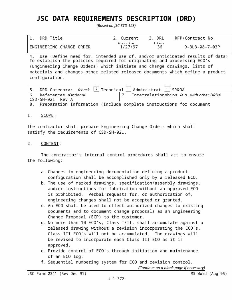
SECTION J-5
PROGRAM PROVISIONING WORK DESCRIPTION (PPWD)00-2.2.1C-220 SBGS Positive Locking Helmet Upgrade & Manifold
Support(Ref. SA 254)$85,087.00
00-2.2.1C-208 R4 EMU/EVA Translation Path Evaluation(Ref. SA 254) $10,127.0000-2.2.1B-201R1 EMU Field Operations (Shuttle)-4th Program Review (Ref. SA
267)$9,457.00
00-2.2.1C-203R1 EMU Related Hardware Development EC (Bldg 34) (Ref. SA 267)
$12,487.00
00-2.2.1C-204R1 EMU Related Equipment Interoperability & Increment Management (Ref. SA 267)
($341.00)
00-2.2.1C-211R2
EMU/EVA Related Equipment Board Coordination (Ref. SA 267)
$110,821.00
00-2.2.1C-212R3 EMU Related Hardware Logistics Database and Data Administration (Ref. SA 267)
$50,970.00
00-2.2.1C-214R2 EMU/EVA Related Hardware Fitcheck Support (Ref. SA 267)
($19,275.00)
01-2.2.1C-301 EMU Related Development and Logistics Activities (EC Station) Bldg. 7 (Ref. SA 267)
$421,433.00
01-2.2.1C-304
EMU Related Equipment Interoperability (Ref. SA 267) $113,468.00
01-2.2.1C-317 EMU Related Equipment Increment Management (Ref. SA 267)
$365,071.00
01-2.2.1C-302 EMU Related EVA Development and Technical Coordination (Ref. SA 269)
$713,000
00-2.2.1C-210R1 EMU EVA Related Equipment/Hardware Manager (Ref. SA283)
$120,675.00
Related Equipment/Hardware Manager
00-2.2.1C-212R4
EMU Related Hardware Logistics Database and Data Administration (Ref. SA283)
$84,112.00
00-2.2.1C-214R3 EMU EVA Related Hardware Fitcheck Support(Ref. SA283)
$120,172.00
00-2.2.1C-231R2 EMU SSA Hardware Modifications to Support the EVA Radiation Monitoring (EVARM) Experiment (Ref. SA283)
$143,540.00
01-2.2.1C-319 GCTC Hydrolab Class III EMU Hardware SustainingEngineering (Ref. SA283)
$258,083.00
01-2.2.1B-303 Bond/Logistics Bldg. 32 for EMU/EVA RelatedEquipment (ER/Shuttle) (Ref. SA 283)
$51,341.00
01-2.2.1C-301R1 EMU Related Development and Logistics Activities(EC Station) Bldg. 7 (Ref. SA 283)
$3,072.00
01-2.2.1C-303 EMU Related Hardware Development (EC Station)Bldg. 34 (Ref. SA 283)
$465,282.00
(Continue on a blank page if necessary)JSC Form 2341 (Rev Dec 91) (MS Word Aug 95) Page 372 of 1

SECTION J-5
PROGRAM PROVISIONING WORK DESCRIPTION (PPWD)01-2.2.1C-314 EMU/EVA Related Hardware Fitcheck Support
(Ref. SA 283)$467,465.00
01-2.2.1C-318 EMU/EVA Related Hardware Tool Request Support(Ref. SA 283)
$125,631.00
01-2.2.1C - 325 Support of EMU SAFER On-orbit Stowage Bag Station NASA Certification (Ref. SA 308)
$19,462.00
01-2.2.1C - 325 R1
Support of EMU Safer On-orbit Storage Bag Station NASA Certification (Ref. SA 308)
$50,290.00
01-2.2.3C -303 Manufacture and Test of Mock-up Insulating cover and sleeve for the IRCO2 sensor head and valve module inlet tube. (Ref. SA 308)
$63,843.00
00-2.2.1C-212R5
DATABASE AND DATA ADMINISTRATION EMU RELATED HARDWARE LOGISITICS (Ref. SA 334)
$ 16,301.00
02-2.2.1C-403 EMU/EVA RELATED EQUIPMENT BOND LOGISTICS BLDG. 32 (ER STATION) (Ref. SA 334)
$55,309.00
02-2.2.1C-402 R1 EMU Related EVA Development and Technical Coordination (XA Station) (Ref. SA 360)
$9,606
02-2.2.1B-404 EMU/EVA Metox Regeneration (Ref. SA 360) $27,851
02-2.2.1C-401R2 EMU RELATED DEVELOPMENT AND LOGISTICS ACTIVITIES (Ref. SA 382)
$27,178.00
02-2.2.1C-416 EMU EVA Translation Path Evaluation and Integration, Operations (Ref. SA 379)
$ 891,525
02-2.2.1B-401 EMU Field XA Shuttle $3,893,90202-2.2.1C-402 EMU Related EVA Development and Technical
Coordination (XA Station) (Ref. SA 379)$ 942,826
02-2.2.1C-401 EMU Related EVA Development and Logistics Activities EC Station Bldg. 7 and EC Station Bldg. 34 (Ref. SA 379)
$ 926,977
02-2.2.1C-410 EMU/EVA Equipment Hardware Integration/Logistics Database (Ref. SA 379)
$1,294,360
02-2.2.1C-417 EMU EVA Increment Management $ 817,408
02-2.2.1C-417R1 EMU/EVA Increment Management (Ref. SA 406) $77,879
02-2.2.1C-410 R1 EMU/EVA Related Equipment Hardware Integration (Ref. SA 406)
($32,578)
(Continue on a blank page if necessary)JSC Form 2341 (Rev Dec 91) (MS Word Aug 95) Page 373 of 1

SECTION J-5
PROGRAM PROVISIONING WORK DESCRIPTION (PPWD)
2.2.2. Pre-Flight and Real-Time Mission Support
99-2.2.2A-101 Pre-Flight and Real-time Mission Support $485,71799-2.2.3C-112 EMU & EVA Related Equipment Life Extension (Ref. SA 192) $25,19100-2.2.2A-201 Pre-Flight & Real Time Mission Support (Ref. SA 203) $796,96201-2.2.2A-301 EVA Pre-flight and Real Time Mission Support GFY 01
(Ref. SA 278)$633,373
01-2.2.2A-302 Technical Training on the Metal Oxide RegeneratorSystem and HSMS Technical Assistance for METOXChamber Testing (Ref. SA 283)
$43,985.00
01-2.2.2A-303 EMU LSS Battery (SV819600) Activation (Ref. SA 283) $16,990.0001-2.2.2A - 303 R1
EMU LSS Battery (SV819600) Activation (Ref. SA 308) $50,342.00
00-2.2.1C -212R7 EMU RELATED HARDWARE LOGISTICS DATABASE AND DATA ADMINISTRATION (Ref. SA 371)
$224,531.00
02-2.2.1C-401R1 EMU RELATED DEVELOPMENT AND LOGISTICS ACTIVITIES (Ref. SA 371)
($134,161.00)
02-2.2.1C-405 EMU/ORU MOCKUP HARDWARE (Ref. SA 371) $126,147.00
02-2.2.1B –403 DEVELOPMENT OF SAFER HAND CONTROLLER ACTUATION RIPCORD (Ref. SA 371)
$43,503.00
02-2.2.1B-405 EMU LOWER ARM CHANGE OUT DEVICE FEASIBILITY STUDY (Ref. SA 371)
$29,877.00
02-2.2.2A-401 Logistics, EVA Pre-Flight and Real Time Mission Support for GFY’ 02 (Ref. SA 379)
$ 623,381
02-2.2.1B-403R1 Development of SAFER Hand Controller Actuation Ripcord (Ref. SA 406)
($18,901)
02-2.2.1B-404R1 EMU/EVA Metox Regeneration (Ref. SA 406) $9,261
2.2.3. Special Studies and Special Test 99-2.2.3C-105 SSA Item 102 – Prototype Extra Large Planar HUT Rework
(Ref SA. 139)$171,352
(Continue on a blank page if necessary)JSC Form 2341 (Rev Dec 91) (MS Word Aug 95) Page 374 of 1

SECTION J-5
PROGRAM PROVISIONING WORK DESCRIPTION (PPWD)99-2.2.3A-102 EMU Power Harness $196,94399-2.2.3C-101 Protective Visor $13,93199-2.2.3C-102 Collapsible Water Reservoir $53,40399-2.2.3C-103 Caution and Warning System $90,72599-2.2.3C-104 EMU Hoist Integration Into SSATA $3,94299-2.2.3A-102R1 Power Harness FY 99 Change of Scope (Ref SA 120) $099-2.2.3C-108 Small Planar HUT & Arm, Canted Waist, Consolidated EMU
Electronics (DCM/CWS/RTDS), and improved Helmet Visibility (Ref. SA 169)
$293,991
99-2.2.3C-103R1 Caution and Warning System Software (Ref. SA 169) $099-2.2.3A-107 Small Planar HUT & Arm, Canted Waist, Consolidated EMU
Electronics (DCM/CWS/RTDS), and improved Helmet Visibility (Ref. SA 169)
$293,993
99-2.2.3C-110 EMU SSA Phase VI Glove Bladder Liner (Ref. SA 175) $88,61999-2.2.3D-101 CWS Redesign (Ref. SA 203) $376,092
99-2.2.3A-107 R2 Small HUT-Expanded Evaluation (Ref. SA 203) $667,050
99-2.2.3A-107 R3 Small HUT-Fitcheck C Hardware Fab (Ref. SA 203) $289,861
99-2.2.3A-111 In-Suit Doppler Design Study (Ref. SA 203) $39,175
99-2.2.3C-204 EMU/REBA/ERCA/SSER EMC Testing (Ref. SA 203) $69,855
99-2.2.5A-120 ILC Dover As a Licensed Production Source For Rucothane For The SSA Applications (Ref. SA 206)
$489,039
00-2.2.5D-206 EMU SSA ELVAX Evaluation on Mini-Sublimator (Ref. SA 206) $6,265
00-2.2.5D-207 EMU SSA ELVAX Certification (Ref. SA 206) $126,296
00-2.2.3A-205 EMU Phase VI Glove Subsystem Manager (Ref. SA 219) $54,885
00-2.2.3A-206 EMU SSA, Disposable In-Suit Drink Bag (DIDB) Location Study (Ref. SA 219)
$52,407
00-2.2.3C-202 CWR Evaluation for EMU Use (Ref. SA 219) $55,334
99-2.2.3A-107 R4 EMU Small HUT Prototype Arm Hardware (Ref. SA 225) $98,714
99-2.2.3C-112 R1 EMU and EMU Related Equipment Life Extension - Phase II (Ref. SA 225)
$54,950
00-2.2.3C-207 EMU AMS-02 Magnetic Exposure Evaluation (Ref. SA 225)
$50,481
00-2.2.5A-201A Phase I Spare PC Board Acquisition for EMU LSS Electrical Items (Ref. SA 241)
$498,669
00-2.2.5D-204 Structure EMU I-131 - Long Lead Material (Ref. SA 241) $33,93400-2.2.5D209 EMU SSA Replacement Material and Mold for BSC Seals
(Ref. SA 241)$89,352
00-2.2.3C-209 EMU RF Crew Protection Evaluation (Ref. SA 243) $80,809.0000-2.2.3C-208 EMU SSA Boot TMG Redesign Feasibility Study
(Ref. SA 243)$39,379.00
00-2.2.3C-207 R1 EMU AMS-02 Magnetic Exposure Evaluation (Ref. SA 243)
$63,667.00
(Continue on a blank page if necessary)JSC Form 2341 (Rev Dec 91) (MS Word Aug 95) Page 375 of 1

SECTION J-5
PROGRAM PROVISIONING WORK DESCRIPTION (PPWD)00-2.2.3C-211 EMU LSS Battery Charger Assembly (BCA) & Middeck
Charger Evaluation (Ref. SA 267)$90,253.00
00-2.2.5A-201R1 DCM/FPS Electronic Parts Procurement (Ref. SA 283) $425,183.00
01-2.2.5A-301 Spectra Webbing, Spectra Cord, Nomex Webbing-Manufacturer Relocation Evaluation (Ref. SA 283)
$50,372.00
00-2.2.3C-202R1 CWR Evaluation for EMU use (Ref. SA 308) ($145.00)01-2.2.3A - 307 Evaluation of New BTA Procedures (Ref. SA 308) $42,855.0001-2.2.3A - 309 Procurement of Training Materials and Instructions
$25,346.00for ASTM Training on Fire Hazards in Oxygen Systems(Ref. SA 308)
$25,346.00
01-2.2.3A - 315 EMU LSS Item 122 IRCO2 Sensor Analysis (Ref. SA 308) $12,696.0001-2.2.3C - 306 Battery Contingency Alternatives (Ref. SA 308) $100,366.0001-2.2.3A - 301 EMU – GENERATION OF GENERIC SPECIFICATION
FOR INTEGRATION OF GFE INTO THE VENILATION LOOP (Ref. SA 334)
$ 71,905.00
01-2.2.3A-306 EXPEDITED EMU TURNAROUND (EET) OF ORU COMPONENTS (Ref. SA 334)
$162,899.00
01-2.2.3A - 313 EMU SSA CLASS III AXIAL RESTRAINT BUFFER EVALUATION (Ref. SA 334)
$ 25,487.00
01-2.2.3C - 308 DEFINITION OF A NEW PREBREATHE VALIDATION TOOL (Ref. SA 334)
$ 86,353.00
01-2.2.3C-309 EVA CREW MEMBER EYE IRRITATION STUDY (Ref. SA 334)
$152,375.00
00-2.2.3A-209 Federal Standard 191A Textile Method Replacement SSA (Ref. SA 360)
$127,744
02-2.2.3C –401 EXTENDING THE USAGE OF CURRENTLY AVAILABLE INCREASED CAPACITY BATTERIES (Ref. SA 371)
$161,867.00
02-2.2.3A –401 PRODUCT PROTECTION ANALYSIS REVIEW (Ref. SA 371) $44,524.00
01-2.2.3C-308R1 DEFINITION OF A NEW PREBREATHE VALIDATION TOOL (Ref. SA 371)
$29,553.00
02-2.2.5D-403 EMU SSA LATEX FOAM REPLACEMENT (Ref. SA 371) $41,696.00
02-2.2.5D-404 EVA ANTI-FOG SURFACTANT REPLACEMENT (Ref. SA 371) $40,755.00
02-2.2.3C-403 DESTRUCTIVE ANALYSIS OF ICB S/N 2006 AND MANUFACTURE/FEASIBILITY TEST OF PROPOSED ICB CONFIGURATION CHANGES (Ref. SA 371)
$146,468.00
00-2.2.2A-201R1 EVA PREFLIGHT AND REAL TIME MISSION SUPPORT FOR GFY ’00 (Ref. SA 371)
($220,399.00)
01-2.2.3A-306R1 EXPEDITED EMU TURNAROUND (EET) OF ORU COMPONENTS) REMOVE OF KSC PATHFINDER FROM TASK) (Ref. SA 371)
($16,656.00)
02-2.2.5D-405 EMU SSA BIC PEN REFORMULATION (Ref. SA 371) $11,617.00
(Continue on a blank page if necessary)JSC Form 2341 (Rev Dec 91) (MS Word Aug 95) Page 376 of 1
SECTION J-5
PROGRAM PROVISIONING WORK DESCRIPTION (PPWD)02-2.2.3A -402 CHRONOLOGICAL LIFE EXTENSION OF SSA SOFT
GOODS (Ref. SA 382) $173,769.00
02-2.2.3C-402 TECHNICAL STUDY OF THE EFFECTS OF THE PHASE V IN-SUIT EXERCISE PREBREATHE PROTOCOL ON THE EMU (Ref. SA 382)
$39,363.00
02-2.2.3A-406R1Fabrication and Evaluation Dome Valve with Disposable In-suit Drink Bag (DIDB) (Ref. SA 406)
$81,972
02-2.2.3A-314 Technology Transfer Glove Study/EC (Ref. SA 406) $19,117
02-2.2.3A-406 Development of Optimized DIDB Requirements (Ref. SA 406)
$38,310
02-2.2.23A-407 EMU and EMU Related EVA Combined CO2/H20 Removal System Assessment (Ref. SA 406)
$106,311
02-2.2.3C-404 Phase VI In-Suit Exercise Pre-breathe Project Team (Ref. SA 406
$21,498
2.2.4. Supplier Supportability / Obsolescence
99-2.2.5a-103 Spacer Fabric Replacement $99,38999-2.2.5a-104 Non-Woven Dacron Fabric Replacement $86,83399-2.2.5a-105 Non-ODS Cleaning Process Fluid Development / Certification $467,63899-2.2.5a-106 DCM Volume Control / Display Intensity Control Potentiometer $56,30599-2.2.5a-107 Hall Effect Sensor $90,32199-2.2.5a-108 Redesign EMU Electrical Transducer Harness $61,18399-2.2.5a-109 Epon 815C $40,61899-2.2.5a-112 Silver Pen Replacement $23,07599-2.2.5a-113 EPI-Cure 3140 $11,08999-2.2.5a-115 Test Valve Replacement $29,20799-2.2.5a-117 Static Seal Material Replacement (Ref. SA 122) $193,25699-2.2.5A-110 Implementation of Replacement for Polyurethanes (Ref. SA
129)$153,222
99-2.2.5A-118 Implementation of Amercoat Replacement Items 121 & 123 (Ref. SA 129)
$9,292
(Continue on a blank page if necessary)JSC Form 2341 (Rev Dec 91) (MS Word Aug 95) Page 377 of 1
SECTION J-5
PROGRAM PROVISIONING WORK DESCRIPTION (PPWD)99-2.2.5A-119 EMU Static Seals, Use of Existing Gordon Rubber (Ref. SA
129) $17,831
99-2.2.5A-111 EMU, SSA, Teflon Coated Fiberglass Fabric Replacement (Ref. SA 175)
$53,299
99-2.2-5A-121 Certification of EVA Tubing (Ref. SA 175) $101,55500-2.2.3C-206 Increased Capacity Battery Wet-Life Extension (Ref. SA 206) $17,97200-2.2.5D-212 EMU SSA Class III Brief / Waist Zipper Replacement
(Ref. SA 254)$38,734.00
00-2.2.5D-214 EMU SSA New Supplier for Fresnel Lenses(Ref. SA 254) $38,367.0001-2.2.5A - 302 Aquapon Coating Replacement Evaluation (Ref. SA 308) $50,314.00
01-2.2.5D-304 EMU PR 420 PRIMER REPLACEMENT(Ref. SA 334) $112,389.0000-2.2.5D-211 Replacement of State Stamp Ink for LSS Hardware
(Ref. SA 360)$58,771
01-2.2.5D-305 Fixing Current I-113 Housing Anodize Process (Ref. SA 360) $91,73202-2.2.5D-401 Nylon Tricot Replacement (Ref. SA 406) $51,74702-2.2.5D-406 Resiweld Adhesive Replacement (Ref. SA 406) $55,838
2.2.6. Orlan Expertise
99-2.2.6A-101 Orlan Expertise $450,73899-2.2.6A-102 Orlan Expertise - Program Review Support $25,84699-2.2.6A-101R1 Orlan Expertise (Ref. SA 120) $099-2.2.6A-102R1 Orlan Expertise (Ref. SA 120) $24,99299-2.2.6A101R2 Orlan Expertise (Ref. SA 122) $40,57799-2.2.6A-103 Orlan Expertise (Ref. SA 162) $1,404,66699-2.2.6A-104 Itegration of ISS1 Crew Request For EMU Hardware Use in
Orlan (Ref. SA 192)$137,652
99-2.2.5A-125 Polymer Separator Material (Ref. SA 203) $48,53600-2.2.5D-203 SSA Glove Finger Material Replacement (Ref. SA 203) $297,77499-2.2.6A-103 R1 Orlan System Expertise (Ref. SA 225) $90,628
00-2.2.6A-202 Orlan-M EVA Information Transition Effort (Ref. SA 243) $269,609.0000-2.2.6A-207 Orlan RF Crew Protection Evaluation and Electro-
magnetic Compatibility Testing (Ref. SA 243)$123,623.00
00-2.2.6A-208 Orlan Micrometeoroid and Orbital Debris Crew ProtectionEvaluation (Ref. SA 243)
$22,480.00
00-2.2.6C-211 Orlan-M EVA System Expertise-Information Transition Effort(Ref. SA 254)
$474,955.00
00-2.2.6C-210 Enhanced Orlan Glove Interoperability(Ref. SA 254) $132,013.0001-2.2.6C-311 ORLAN-M EVA SYSTEMS EXPERTISE (Ref. SA 271) $1,247,790
99-2.2.6A 103 R2 ORLAN SYSTEM EXPERTISE (Ref. SA 334) ( $ 12.00)
01-2.2.6C-307 EMU TECHNICAL ASSISTANCE FOR METOX $ 73,149.00(Continue on a blank page if necessary)
JSC Form 2341 (Rev Dec 91) (MS Word Aug 95) Page 378 of 1
SECTION J-5
PROGRAM PROVISIONING WORK DESCRIPTION (PPWD)(Ref. SA 334)
01-2.2.6C-311 R1 ORLAN-M EVA SYSTEMS EXPERTISE (Ref. SA 334) ($ 2,209.00)
01-2.2.6C-314 EMU AND EMU RELATED EVA EQUIPMENT LAUNCH RESTRAINT FEASIBILITY STUDY (Ref. SA 334)
$265,762.00
02-2.2.6C-411 Orlan-M EVA Systems Expertise (Ref.. SA 379) $1,512,034
(Continue on a blank page if necessary)JSC Form 2341 (Rev Dec 91) (MS Word Aug 95) Page 379 of 1

SECTION J
LIST OF ATTACHMENTS
SECTION J-6
HARDWARE QUANTITIES AND DELIVERY SCHEDULES*
This attachment sets forth the delivery schedules for the contract end items to be delivered against the requirements of Statement of Work, Section C:
Description Part Number ITEMQTYFY98
QTYFY99
QTYFY00
QTY
FY01
Primary Oxygen Pressure Sensor SV778528-2 112 9Pressure Suit Sensor SV767788-2 114 1 6Shear Plate Assembly SV778540-49 115 2Pitot Actuated Valve SV769480-4 125 2 1 2Feedwater Supply Pressure Sensor SV767793-7 (ref. SA 31) 132 6Feedwater Relief Valve SV769404-7 135 2 2Water Relief Valve SV769405-3 142 1 1 1Water Check Valve SV769406-2 143 1 2 1Coolant Isolation Valve Assembly SV784998-2 171/1
722 1
Pressure Transducer & Connector SV785018-6 215 0 0 0 0(refSA 358)
Suit Pressure Gauge SV767706-5 311 2 2Purge Valve SV787027-3 314 1Volume Control SV767784-1 360
611/26/99Ref. SA
199 Display Intensity Control SV767785-1 361
611/26/99Ref. SA
199 EVC Mode Selector Switch SV767786-2 362 5Push-to-Talk Switch SV767794-2 365 6Fan Switch SV771887-3 366 4Feedwater Valve Switch SV767795-3 367 6Caution & Warning System Switch SV767792-2 368 5Increased Capacity Battery (ref. SA 32) SV819600-TBD 490 24 24Glove Customization (pairs) (less Wrist Bearings)
0106-212147Ref. SA 42/SA 85
2 19 0 0
Gloves (pairs) (less Wrist Bearings) 0106-812076 2 17 17 12Paraderm Comfort Glove (pairs) ST91G3045 50 100 1004750 TMG (pairs) 0106-811768 4 11 21 16
Spare Glove Bladders (pairs) 0106-811648 1 5 6 5Heater Electronic Systems (These items will be incorporated into the TMGs, Gloves, Glove Customizations)
0106-211745 7 33 44 32

SECTION J-5
PROGRAM PROVISIONING WORK DESCRIPTION (PPWD)Lower Arms (pairs) 0103-210152-XX-XX 5 5Arm Sizing Ring (pairs) 10146-03 2 3
Brief 0104-810598-03 2 2Thigh sizing Ring (pairs) 10159-02 2 3Boot Sizing Ring (sets) 10157-02, 10202-02,
10203-022 3
Legs (pairs) 0104-210575-XX-XX 3 4Boots Disconnect (pairs) 10154-02 2 2Boots (pairs) (Less disconnects) 0104-89652-XX/XX 2 3Waist Bearing 16” 10057-03 2 2D/S Wrist Disconnect (pairs) 10088-02 3 3Waist 16” (Restraints/ Bladders/TMGs) 0104-82347-XX-XX
0104-82692-XX-XX3
Delete (3)per
CCO 230
3 Delete
(3)per
CCO 230
LCVG assembly 0107-84029-18-XX 7 16 5BLVD 0107-81057-XX/XX-XX 8 16 6BSC 16” 9787-07 2 3 2SEMU (SSAPH) Wiring Harness (PRS) 0800-111983 13 12 6Arm (SSAPH) Wiring Harness (PRS) 0103-111984 24 44 15Visor (sets) Sun Visor Protective Visor
25747-123861-2
2 2 2 2
Gloves (pairs) (less Wrist Bearings) 0106-812076 8 8 5 3Paraderm Comfort Gloves (pairs) ST91G3045 50 50 50 254750 TMG (pairs) 0106-811768 7 2 2 1
Spare Glove Bladders (pairs) 0106-811648 2 1 1 1Heater Electronic Systems (These items will be incorporated into the TMGs, Gloves, Glove Customizations)
0106-211745 17 11 8 5
* All deliveries shall be “on or before” within fiscal year spending constraints.Ref. SA 6 Production and deliver of the following 16 HUT TMGs are as follows:
Description Part Number Quantity Delivery Date
HUT TMG, Training, Large TBD 2 1/1/98
HUT TMG, Training, Large TBD 2 8/15/98
HUT TMG, Flight, Large TBD 3 4/30/98 (Ref. SA 49)
HUT TMG, Flight, Large TBD 3 5/1/98
HUT TMG, Flight, Large TBD 1 10/1/98
(Continue on a blank page if necessary)JSC Form 2341 (Rev Dec 91) (MS Word Aug 95) Page 381 of 1

SECTION J-5
PROGRAM PROVISIONING WORK DESCRIPTION (PPWD)
HUT TMG, Flight, Large TBD 2 1/1/99
HUT TMG, Flight, Large TBD 1 3/1/98
HUT TMG, Training, Medium TBD 1 5/15/98
HUT TMG, Flight, Medium TBD 1 8/1/98
Ref. SA 12 Description Part Number Item Quantity Delivery Date
Vent Flow Sensor SV771836-29 121 1 8/31/99
Feedwater Shutoff Valve SV767660-10 137 2 4/30/99Feedwater Shutoff Valve SV767660-10 137 2 6/31/99Feedwater Shutoff Valve SV767660-10 137 2 8/31/99Feedwater Shutoff Valve SV767660-10 137 2 10/31/99
Ref. SA 128Positive Pressure Relief Valve SV787036-10 146 7 2/28/99Positive Pressure Relief Valve SV787036-10 146 2 4/30/99Positive Pressure Relief Valve SV787036-10 146 3 10/31/99
Ref. SA 128Negative Pressure Relief Valve SV785927-2 147 8 1/31/99Negative Pressure Relief Valve SV785927-2 147 3 3/31/99Negative Pressure Relief Valve SV785927-2 147 5 10/31/99
Purge Valve SV787027-3 314 5 1/31/99Purge Valve SV787027-3 314 6 10/31/99
Sublimator and Harness SV805280-3 139/140 1 5/31/00Sublimator and Harness SV805280-3 139/140 1 2/28/01
Gas Trap Details SV784939-1, SV784941-1 141 18 10/31/98
*Secondary Oxygen Pack SV799045-00-02 200 1 6/30/00
Oxygen Water Manifold SV779301-13 385 1 2/29/00
Ref. SA 77 EMU Electrical Harness SV767690-02 440 3 5/31/00EMU Electrical Harness SV767690-02 440 4 7/31/00EMU Electrical Harness SV767690-02 440 7 9/30/00EMU Electrical Harness SV767690-02 440 7 11/30/00*With Lemo CCA and bio-med connectors
Vent Flow Sensor Refurb SV771836-29 121 1 FY '98Vent Flow Sensor Refurb SV771836-29 121 1 FY '99
(Continue on a blank page if necessary)JSC Form 2341 (Rev Dec 91) (MS Word Aug 95) Page 382 of 1

SECTION J-5
PROGRAM PROVISIONING WORK DESCRIPTION (PPWD)Vent Flow Sensor Refurb SV771836-29 121 1 FY '00
Fan/Pump/Separator Refurb SV787994 123 1 FY '99Fan/Pump/Separator Refurb SV787994 123 1 FY '00
* The above estimated delivery date is contingent upon Hamilton Standard receiving the following hardware.
QTY DESCRIPTION PART NUMBER AVAILABLE LOCATION
NEED DATE
1 EMU Item 215 Transducer & Connector SOP
(S/N 2004-3-559) SV7850186
Bond H.S. 8/31/98
1 EMU Item 213 Pressure Control Module
(S/N 114) SV7990423
BAO/FEPC Call Task 4-164
8/31/98
1 EMU Item 210 Bottle Secondary, Oxygen
(S/Ns TBD) SV809816-1
Bond H.S. 8/31/98
1 EMU Item 200 Sub-assembly Bracket & Inserts, Mounting
SV789141-1 Bond H.S. 8/31/98
Ref. SA 13 *Retrofit ten (10) 02/H20 Manifold Assembly, SV7779301-9, Item 385Receipt of GFE (4/98, 8/98, 12/98, 4/99, 7/99, 12/99, 4/00, 8/00, 10/00, 3/01)
*Retrofit thirteen (13) Service & Cooling Umbilicals, SV767730-09, Item 400Receipt of GFE (9/98, 10/98, 11/98, 12/98, 1/99, 2/99, 3/99, 4/99, 9/99, 7/99, 12/99, 4/00, 5/00)
Delivery of the following hardware will be 1 unit per month starting November 1998 provided that the hardware (GFE) is received at least 3 months prior to ship date. If GFE not received as scheduled, there will be a corresponding slip in the delivery schedule.
*Retrofits are per FCCP-069. Work outside the scope defined within FCCP-069 will require equitable adjustment (Cost & Schedule)
Ref. SA 24Description Part Number Item Delivery DatePrimary Life Support Subsystem (PLSS) SV799100-11-00, S/N 1018 100 11/99
Delivery of the following hardware is contingent upon receipt of GFE prior to April 1, 1998 from Boeing. NASA to provide ORU component details for assembly April 1, 1999; under separate direction associated to EMU FCCP 075, Phase III Production of ORU Kits.
Item Number Part Number Description Quantity Required
(Continue on a blank page if necessary)JSC Form 2341 (Rev Dec 91) (MS Word Aug 95) Page 383 of 1

SECTION J-5
PROGRAM PROVISIONING WORK DESCRIPTION (PPWD)114 SV767788-2 Suit Pressure Sensor 1
115 SV778540-49 Shear Plate Assembly 1 121 SV771836-29 Check Valve and Vent Flow Sensor 1122 SV809286-4 CO2 Sensor 1123 SV787994-11 Fan/ Separator/Pump Assembly 1127/128 SV784996-5 Check Valve and Filter 1132 SV767793-7 Feedwater Pressure Sensor 2136 SV792528-5 Feedwater Pressure Regulator 1138 SV767793-8 Feedwater Pressure Sensor 1139/140 SV805280-3 Sublimator and Harness 1141 SV805257-1 Gas Trap 1142 SV769405-3 Water Relief Valve 1143 SV769406-2 Water Check Valve 1146 SV787036-10 Positive Pressure Relief Valve 1147 SV785927-2 Negative Pressure Relief Valve 1150 SV785970-13 Caution and Warning System 1156 SV789134-2 RTDS Harness 1171/172 SV784998-2 Coolant Isolation Valve Assembly 2174 SV791230-2 RTDS 1
SV809322-1 Impact Shield 1 SV798853-1 Small Bladder 2
SV798854-1 Large Bladder 1 SV771392-5 Striker Plate 2
Ref. SA 26 Description Part Number Size Qty. Delivery Date
Enhanced Lower Arm 0103-210152-05/06 02 1 pair 3/99(Without Fab Attach Rings) 0103-210152-05/06 03 1 pair 3/99
0103-210152-05/06 04 1 pair 3/99Enhanced Brief 0104-810598-05 03(16") 1 each 3/99(Without Fab Attach Rings & Brac)Enhanced Leg Assembly 0104-210575-01/02 02 1 pair 3/99Enhanced Leg Assembly 0104-210575-01/02 03 1 pair 3/99
Ref. SA 28 Description Part Number Quantity Delivery Date
EMU Battery SV767789-12-00 6 10/30/98EMU Battery SV767789-12-00 6 11/31/98EMU Battery SV767789-12-00 6 12/31/98
Ref. SA 29Description Part Number Quantity Delivery Date
(Continue on a blank page if necessary)JSC Form 2341 (Rev Dec 91) (MS Word Aug 95) Page 384 of 1

SECTION J-5
PROGRAM PROVISIONING WORK DESCRIPTION (PPWD)Retention Ring SV817711 3 PRS 5/31/98
9 PRS 7/31/9820 PRS 9/30/98
Ref. SA 30 Description Part Number Quantity Delivery Date
02 Frame & Filter Assemblies SV778902-1 10 7/30/98
Ref. SA 53Production of one (1) pair of size 6HR Phase VI Gloves to be built and placed in inventory. This includes the necessary non-recurring costs to rework the size 6HR palm molds. The existing molds, originally built for development and testing, will be updated to the current flight configuration. The TMG's require the incorporation of the current ORU features and palm area TMG updates.
Ref. SA 39Description Part Number Quantity Delivery Date
6HR Phase VI Gloves 0106-212147-01/02 1 pair 5/9/99 (Ref. SA 141)
Ref. SA 60 QuantityDescription Part Number CTSD BAO/FEPC Delivery by:
Static Seal, Arm Bearing 25570 12 ea 50 ea 9/13/98& Arm Sizing Ring
Static Seal, Thigh FAR 25410 12 ea 75 ea 9/13/98& Thigh Sizing Ring
Static Seal, Boot FAR 25417 16 ea 60 ea 9/13/98& Leg Sizing Ring
Ref. SA 73The Production of three (3) Combination Purge Valves (with orificies) and provide HSMS/ILC field support for flow testing of six (6) orifices at NASA/JSC. The three (3) CPV Orifices will be delivered for test by 10/13/98. The PDA Orifice testing, including three (3) spares at JSC will be completed by 10/31/98. The three (3) CPVs will be of the latest configuration after incorporation of the CPV Housing drawing change authorized by CCBD H6820 (Supplemental Agreement 50).
Description Part Number Quantity Delivery Date
Combination Purge Valve Assembly 9819-08 3 12/31/99 GFY GFY
Ref. SA 95 (Continue on a blank page if necessary)
JSC Form 2341 (Rev Dec 91) (MS Word Aug 95) Page 385 of 1

SECTION J-5
PROGRAM PROVISIONING WORK DESCRIPTION (PPWD) Description Part Number '00 '01 Total
Partial ORU PLSS Kit Details:Item 151 Maintainable Harness SV824051 12 3 15Item 152 Maintainable Harness SV824052 12 3 15 Electrical Bracket (151/152) SV819597 12 3 15
02 Hi-Pressure Housing AssemblySV822942 12 3 1502 Actuator Slide Assembly SV823932 12 3 15Connector Rotary AssistanceTabs, SV823037, SV823046, 12 3 15
SV823939
ORU HUT Kit Details:J10 Connector Cup SV823105 12 3 15Upper/Lower Planar HUT Mounts SV822967, 12 6 18w/Adjustable Nuts SV822968, SV822969
ORU DCM Kit Details:Item 391 Jumper Harness SV821755 12 2 14Item 392 Jumper Harness SV821756 12 2 14DCM Captivator Assembly SV823611, SV822972 12 2 14
CCV Handle Guard SV822933 12 2 14DCM Mode Selector Switch SV822970 12 2 14
Six (6) of the twelve (12) GFY ’00 deliveries will be delivered on or before 11/30/99.
One set of ORU PLSS Kit details will be delivered to HSSSI Bonded Stores for assembly into the PLSS S/N 1018 (currently at Windsor Locks). Individual details of this Kit may be delivered and assembled prior to Kit completion.
Two sets of Partial ORU PLSS Kit details will be delivered to HSSSI Bonded Stores for assembly into Shear Plate Assemblies (SV778940-49) required in Section J-6 of Contract NAS9-97150. Direction from NASA Contracting Officer will be required to add the ORU PLSS Kit details to the Shear Plate Assemblies.
REF. SA 100Item Part Number FY'98 FY'99
From: Legs (pairs) 0104-210575-03 3 4
Item Part Number Quantity Delivery Date
(Continue on a blank page if necessary)JSC Form 2341 (Rev Dec 91) (MS Word Aug 95) Page 386 of 1

SECTION J-5
PROGRAM PROVISIONING WORK DESCRIPTION (PPWD)To: Legs (pairs) 0104-210575-04-01 1 pair 08/30/99
Legs (pairs) 0104-210575-04-02 2 pair 09/30/99Legs (pairs) 0104-210575-04-03 4 pair 11/30/99
Item Part Number FY'98 FY'99
From: Boots (pairs) 0104-210895-09/10 or -11/12 2 3
Item Part Number Quantity Delivery Date
To: Boots (pairs) 0104-210895-15/16-01 1 pair 10/30/99Boots (pairs) 0104-210895-13/14-02 1 pair 11/30/99Boots (pairs) 0104-210895-13/14-02 3 pair 01/24/00
Item Part Number FY'98 FY'99
From: Brief 0104-810598-05 2 2
Item Part Number Quantity Delivery Date
To: Brief 0104-810598-06-03 2 pair 7/30/99Brief 0104-810598-06-03 2 pair 11/30/99
Item Part Number FY'98 FY'99
From: Lower Arms (pairs) 0103-210152-05/06 or 07/08 5 5
Item Part Number Quantity Delivery Date
To: Lower Arms (pairs) 0103-210152-13/14-01 2 pair 07/30/99Lower Arms (pairs) 0103-210152-13/14-02 1 pair 07/30/99Lower Arms (pairs) 0103-210152-13/14-02 2 pair 08/30/99Lower Arms (pairs) 0103-210152-13/14-03 2 pair 10/30/99Lower Arms (pairs) 0103-210152-15/16-04 2 pair 11/30/99Lower Arms (pairs) 0103-210152-15/16-05 1 pair 11/30/99
Ref. CCO 230
EMU SSA On-Orbit Adjustable Waist Certification and Production
The Contractor is directed to produce 37 Adjustable Waist Restraint/Bladder Assemblies and TMGs and revise the first flight to STS-104 (7A). With the revised first flight, a single mission certification is no longer required.
Deliverables are the following:USA CTSD Delivery
(Continue on a blank page if necessary)JSC Form 2341 (Rev Dec 91) (MS Word Aug 95) Page 387 of 1

SECTION J-5
PROGRAM PROVISIONING WORK DESCRIPTION (PPWD)Description Size Quantity Quantity Date
0104-81235-01-01Rest/Blad. Short 2 - 1/18/010104-812454-01-01 TMG
0104-81235-01-02 Rest/Blad. Long 2 - 2/15/010104-812454-01-02 TMG
0104-81235-01-01Rest/Blad. Short 1 1 3/15/010104-812454-01-01 TMG
0104-81235-01-02 Rest/Blad. Long 1 1 4/20/010104-812454-01-02 TMG
0104-81235-01-01Rest/Blad. Short 3 1 7/6/010104-812454-01-01 TMG
0104-812355-01-02 Rest/Blad. Long 3 1 9/13/010104-812454-01-02 TMG"
Ref. SA 322EMU SSA On-orbit Adjustable Waist Certification and Production
(Continue on a blank page if necessary)JSC Form 2341 (Rev Dec 91) (MS Word Aug 95) Page 388 of 1

SECTION J-5
PROGRAM PROVISIONING WORK DESCRIPTION (PPWD)
Ref. SA 253
The contractor is hereby directed to manufacture a new shear plate assembly (SV778540) configuration by replacing the two (2) front screws (NAS1189E06T6LK) with shorter screws (NAS1189E06T5LK) to secure the oxygen actuator assembly. The contractor is, therefore, directed to ship the following screw kits for incorporation into the shear plate assembly.
Description Part Number ITEMQTYFY98
QTYFY99
QTYFY00
QTYFY01
(Continue on a blank page if necessary)JSC Form 2341 (Rev Dec 91) (MS Word Aug 95) Page 389 of 1
Description SizeUSA
Quantity CTSD Quantity Delivery Date
0104-812355-01-01 Rest/Blad. 0104-812454-0101 TMG Short 2 0 01/18/2001
0104-812355-01-02 Rest/Blad. 0104-812454-01-02 TMG Long 2 0 02/15/2001
0104-812355-01-01 Rest/Blad. 0104-812454-0101 TMG Short 1 1 03/15/2001
0104-812355-01-02 Rest/Blad. 0104-812454-01-02 TMG Long 1 1 04/20/2001
0104-812355-01-01 Rest/Blad. 0104-812454-01-01 TMG Short 3 1 07/06/2001
0104-812355-01-02 Rest/Blad. 0104-812454-01-02 TMG Long 3 1 09/13/2001
0104-812355-01-01 Rest/Blad. 0104-812454-01-01 TMG Short 4 0 11/26/2001
0104-812355-01-02 Rest/Blad. 0104-812454-01-02 TMG Long 4 0 02/04/2002
0104-812355-01-01 Rest/Blad. 0104-812454-01-01 TMG Short 4 0 04/19/2002
0104-812355-01-02 Rest/Blad. 0104-812454-01-02 TMG Long 4 0 07/01/2002
0104-812355-01-01 Rest/Blad. 0104-812454-01-01 TMG Short 5 0 09/27/2002

SECTION J-5
PROGRAM PROVISIONING WORK DESCRIPTION (PPWD)
Retrofit Kit, O2 Actuator Assembly
SV28219 50 Kits*
*NOTE: One (1) Retrofit Kit contains two (2) screws (P/N NAS 1189E06T5LK).
Ref. SA 353 (CCO 281)Phase VI Spares
DESCRIPTION PART NUMBER SIZE CLASS QTY DELIVERY DATEPHASE VI: BLADDERS 0106-812537-01/02 6LA III 1 PAIR 3/28/01BLADDERS 0106-812537-01/02 6MA III 1 PAIR 3/16/01BLADDERS 0106-812537-01/02 6HR III 1 PAIR 3/16/01BLADDERS 0106-812537-01/02 6WS III 1 PAIR 4/4/01BLADDERS 0106-812537-01/02 6TA III 1 PAIR 4/2/01BLADDERS 0106-812537-01/02 6CR III 1 PAIR 7/28/01BLADDERS 0106-812537-01/02 6GH III 1 PAIR 3/16/01BLADDERS 0106-812537-01/02 6HM III 1 PAIR 4/14/01BLADDERS 0106-812537-01/02 6HD III 1 PAIR 6/27/01BLADDERS 0106-812537-01/02 6US III 1 PAIR 6/23/01BLADDERS 0106-812537-01/02 6PZ III 1 PAIR 6/22/01BLADDERS 0106-812537-01/02 6VS III 1 PAIR 9/23/01BLADDERS 0106-812537-01/02 6NO III 1 PAIR 3/29/01BLADDERS 0106-812537-01/02 6BB III 1 PAIR 9/30/01
TMG 0106-812107-01/02 6US III 1 PAIR 5/18/01TMG 0106-812107-01/02 6HR III 1 PAIR 6/25/01TMG 0106-812107-01/02 6VS III 1 PAIR 6/25/01TMG 0106-812107-01/02 6HM III 1 PAIR 6/25/01TMG 0106-812107-01/02 6HD III 1 PAIR 6/16/01TMG 0106-812107-01/02 6CR III 1 PAIR 6/29/01TMG 0106-812107-01/02 6RY III 1 PAIR 7/5/01TMG 0106-812107-01/02 6LA III 1 PAIR 7/14/01TMG 0106-812107-01/02 6TU III 1 PAIR 7/20/01TMG 0106-812107-01/02 6BC III 1 PAIR 7/20/01TMG 0106-812107-01/02 6MA III 1 PAIR 8/10/01TMG 0106-812107-01/02 6MA III 1 PAIR 8/24/01TMG 0106-812107-01/02 6NO III 1 PAIR 8/10/01TMG 0106-812107-01/02 6WS III 1 PAIR 8/24/01TMG 0106-812107-01/02 6WT III 1 PAIR 9/8/01TMG 0106-812107-01/02 6FN III 1 PAIR 9/28/01TMG 0106-812107-01/02 6MT III 1 PAIR 9/30/02
(Continue on a blank page if necessary)JSC Form 2341 (Rev Dec 91) (MS Word Aug 95) Page 390 of 1
SECTION J-5
PROGRAM PROVISIONING WORK DESCRIPTION (PPWD)
RESTRAINTS 0106-812810-03/04 6CR III 1 PAIR 8/9/01RESTRAINTS 0106-812810-03/04 6PZ III 1 PAIR 8/3/01RESTRAINTS 0106-812810-03/04 6MA III 1 PAIR 8/3/01RESTRAINTS 0106-812810-03/04 6MA III 1 PAIR 8/18/01RESTRAINTS 0106-812810-03/04 6US III 1 PAIR 8/9/01RESTRAINTS 0106-812810-03/04 6NO III 1 PAIR 8/9/01RESTRAINTS 0106-812810-03/04 6LA III 1 PAIR 8/22/01RESTRAINTS 0106-812810-03/04 6TA III 1 PAIR 8/9/01RESTRAINTS 0106-812810-03/04 6WS III 1 PAIR 8/9/01RESTRAINTS 0106-812810-03/04 6BB III 1 PAIR 9/19/01
Ref.: SA 287EMU LSS ORU TOOL DESIGN AND CERTIFICATION
The contractor is directed to fabricate and certify ORU change-out tools and aids necessary for flight STS-104/7A. These tools will be stowed in the EMU Servicing Kit via a Type “A” TPS. Three tool sets shall be delivered in accordance with the following delivery schedule:
Flight: Item: Class: Qty: Delivery Due Date:N/A Tool Set III 1 Set January 31, 2001STS-104/7A Tool Set I 1 Set February 16, 2001N/A Tool Set I 1 Set February 16, 2001
The following list and quantities represent three complete sets of ORU change-out tools and aids:
Hand Tools Drawing QuantityHex Head Drive, 3/8" Driver, 3/16" x 6" SED39136018 3
Ball Hex Head Driver, 3/8" Drive, 1/4" x 6 in.SED39136017-01 3
Ball Hex Head Driver, 3/8" Drive, 5/32" x 5 in.SED39136017-02 3
SOP Over-ride Protection Tool SED39136015 6DCM O2 Fill-Line O-Seal Spare STSV047AD011 6DCM O2 Fill-Line Back-up Ring Spare STSV058F11 or
STSV058G1112
PLSS Interface, FW 18 Filter, O-Seal Spare STSV047N112 6PLSS Interface, LCG Port, O-Seal Spare STSV047N016 24PLSS Interface, Vent Loop, O-Seal Spare STSV047N025 6PLSS Interface, Seondary, O-Seal Spare STSV047N049 6DCM Interface, FW O-Seal Spare STSV047N011 6DCM Interface, LCG Water, O-Seal Spare STSV047N014 24DCM Interface, Sense Port, O-Seal Spare STSV047N009 6DCM Interface, Purge Valve Port, O-Seal Spare STSV047N016 6DCM Interface, Secondary, O-Seal Spare STSV047N042 6
(Continue on a blank page if necessary)JSC Form 2341 (Rev Dec 91) (MS Word Aug 95) Page 391 of 1

SECTION J-5
PROGRAM PROVISIONING WORK DESCRIPTION (PPWD)SOP Interface O-Seal Spare STSV047N015 6
Teflon Squares, 2x2; 5x7SED39136016-01;-02 150
REF. SA 317ORU PLSS-SOP, DCM AND PLANAR HUT TMGS
The Contractor is directed to fabricate and ship flight & training ORU PLSS-SOP, DCM, and Planar HUT TMGs as follows:
TMG Description Class I QTY Class III QTY Delivery Date
DCM 3 3* 09/15/00
(P/N 0100-811998-01) 5* 1 12/15/00
6 03/31/013 05/31/01
3 07/31/01
PLSS 3 3* 11/15/00
(P/N 0100-811994-02) 1* 03/08/011*
03/26/011* 02/20/011* 03/02/012* 02/15/01
2 05/31/011
06/30/01 107/02/01
1 07/16/011 04/30/01
1 1 07/30/011
08/13/011 08/27/011 09/10/01
HUT 1 LG 10/31/00
(Continue on a blank page if necessary)JSC Form 2341 (Rev Dec 91) (MS Word Aug 95) Page 392 of 1

SECTION J-5
PROGRAM PROVISIONING WORK DESCRIPTION (PPWD)(Lg. P/N 0102-812000-02-03) 3 LG & 1 MED 1 LG 01/15/01
Med. 2 LG 2 LG & 2 MED 04/15/01
(P/N 0102-812000-02-02)1 LG & 1 MED 1 LG 06/30/01
2 LG & 1 MED 07/30/01
1 LG 2 LG 09/30/01
2 MED 1 MED 10/29/012 LG & 1 MED2 LG 2 LG 12/30/01
1 MED 01/28/02
1 MED 1 LG 02/28/02
1 MED 1 MED 04/1/02
*One (1) Class III PLSS TMG and DCM TMG will be delivered to CTSD for the ORU Hi Fi MockupOne (1) Class I PLSS TMG and DCM TMG will be delivered to CTSD for assembly into PLSS 1004 and DCM 2007Also, one (1) Class III DCM TMG will be delivered to MOD
NOTE: THE ABOVE DELIVERABLES MAY BE DELIVERED AS CLASS I IN LIEU OF CLASS III.
Ref. SA 327EMU SSA In-line Cable Voltage Regulator (ILCVR) Certification
Nomenclature Quantity Delivery Date
In-Line Cable Voltage 6 12/12/01 Regulator (0801-112983-01)
O2 Pocket Connector 6 12/12/01 Extension (0102-812936-01)
Certification closure by 11/1/01
Ref. SA 328ORU Tool Kit Design, Fabrication and Certification The delivery schedule for the ORU Tool Kits is as follows:
(Continue on a blank page if necessary)
JSC Form 2341 (Rev Dec 91) (MS Word Aug 95) Page 393 of 1
SECTION J-5
PROGRAM PROVISIONING WORK DESCRIPTION (PPWD)Quantity Class Delivery Date
1 Class III 04/05/02 (Ref. SA 355) 1 Class I 06/07/02 (Ref. SA 355) 2 Class I 08-21-02 (Ref. SA 355)
Certification approval by 04/30/02. (Ref. SA 355) Crew consensus required by 02/19/02. (Ref. SA 355)
Ref. SA 332
H7164 EMU HUT and DCM ORU Delta Certification for Space Shuttle Stowage as CEIsThe delivery schedule is as follows:
NOMENCLATURE DUE DATE Certification February 22, 2002. Hardware May 1, 2002 -Two kits of HUT
hardware. Hardware May 20, 2002 -Three kits of HUT
hardware and balance of hardware.
Ref. SA 336
The following are deliverables to support field retrofit of Class I and III enhanced Small Boot TMGs:
Quantity Nomenclature Due Date
14 pairs Toe spacers 2/12/2002
14 pairs Mod kits 2/12/2002
Certification closure by 12/17/01.
Ref. SA 338
Deliveries are revised to the following:Delivery on or
before6LE Class I gloves (Prime) with Newman (6LN) palm bars 10/23/01
(Continue on a blank page if necessary)JSC Form 2341 (Rev Dec 91) (MS Word Aug 95) Page 394 of 1

SECTION J-5
PROGRAM PROVISIONING WORK DESCRIPTION (PPWD)6LE Class I gloves (back up) with Newman (6LN) palm bars 12/08/016NM Class I gloves (back up) 12/08/01
REF. SA 342
Item Quantity Delivery Date12V Heater In-Line Cable 5 On or before 01 April 2001Voltage Regulator Assemblies
12V Heater In-Line Cable 1 On or before 11 May 2001Voltage Regulator Assembly
12V Heater In-Line Cable 2 On or before 11 June 2001Voltage Regulator Assemblies
Ref. SA 344For Use on
Item Class Quantity Flight
DIDB Bite Valve Guard III 10 N/A(Prototype P/N: SK8010-20317-04)
DIDB Bite Valve Guard (P/N: 0110-213024-01) I 20 7A
DIDB Bite Valve Guard (P/N: 0110-213024-01) I 50 7A.1
Ref. SA 345
Item Quantity Date
Prototypes for NBL Training ship to CTSD 12 9/26/01
Class I Unit to Support STS-108 (UF-1) flight 25 10/31/01
Class I Unit to Support STS-109(HST) training &flight 40 11/16/01
Certification closure by 10/23/01.(Continue on a blank page if necessary)
JSC Form 2341 (Rev Dec 91) (MS Word Aug 95) Page 395 of 1
SECTION J-5
PROGRAM PROVISIONING WORK DESCRIPTION (PPWD)
Ref. SA 346CCBD H7105
Item Delivery Date
S/N 008 On or before July 31, 2002 (GFE Required by 1/02) S/N 009 On or before October 31, 2004 (GFE Required by 3/04)
S/N 019 On or before October 31, 2004 (GFE Required by 3/04)
Ref. SA 352 (CCO 118 and Revisions)Phase VI Implementations
Customization Production:Crewmember Size Voltage Date DeliveredWhitson 6WT 12 6/29/00Mastracchio 6MT 12 11/3/00Coleman 6C 12 10/26/00A. Thomas 6TS 12 11/22/00Richards 6RH 12 3/8/01Forrester 6FR 12 4/2/01Linnehan 6LN 12 3/14/01Culbertson 6CU 12 6/22/01Magnus 6MG 12 8/8/01Newman 6NM 12 10/19/01Lu 6LL 12 11/16/01Currie 6CY 12 2/22/02Morin 6MO 12 2/1/02
Thomas, Don 6TM 12 3/1/02Pettit 6PT 12 7/13/02Robinson 6RB 12 3/22/02Williams J 6WL 12 8/9/02Piper 6PP 12 8/23/02
Flight (Class I) Production Gloves:Crewmember Size Voltage Date Delivered
Malenchenko 6MA 3 11/17/99Lu 6MA 3 9/30/99Malenchenko 6MA 3 11/9/99Williams 6MA 3 11/12/99Tanner 6TA 12 4/7/00Tanner 6TA 12 5/10/00Curbeam 6CR 12 5/19/00
(Continue on a blank page if necessary)JSC Form 2341 (Rev Dec 91) (MS Word Aug 95) Page 396 of 1
SECTION J-5
PROGRAM PROVISIONING WORK DESCRIPTION (PPWD)Curbeam 6CR 12 6/8/00Jones 6WS 12 6/16/00Jones 6WS 12 7/28/00Polansky 6BY 12 4/19/00 Switched
with reworked glove for Garneau
Usachev 6US 12 8/16/00Usachev 6US 12 10/10/00Helms 6HM 12 7/28/00Helms 6HM 12 8/18/00Hadfield 6HD 12 8/16/00Hadfield 6HD 12 9/6/00Parazynski 6PZ 12 9/21/00Parazynski 6PZ 12 10/23/00Voss (James) 6VS 12 11/20/00Voss (James) 6VS 12 12/4/00
Flight (Class I) Production Gloves Con’t:Crewmember Size Voltage Date
DeliveredRichards 6HR 12 11/22/00Richards 6HR 12 12/12/00A. Thomas 6US 12 11/21/00A. Thomas 6US 12 12/15/00Reilly 6RY 12 12/21/00Reilly 6RY 12 1/29/01Fincke 6FN 12 1/4/01Spare 6WS 12 12/14/00Phillips 6CR 12 1/29/01Onufriyenko 6NO 12 4/2/01Gernhardt 6GH 12 2/20/01Gernhardt 6GH 12 3/9/01Hobaugh 6PZ 12 2/23/01Spare 6PZ 12 2/27/01Spare 6BB 12 3/29/01Turin 6TU 12 4/20/01Barry 6BY 12 4/25/01Burbank 6BB 12 6/15/01Turin 6TU 12 5/8/01Fincke 6FN 12 5/18/01Massimino 6BB 12 7/5/01Bursch 6BC 12 6/8/01Burbank 6BB 12 7/26/01Onufriyenko 6NO 12 6/22/01Bursch 6BC 12 6/29/01Massimino 6BB 12 7/6/01Godwin 6HM 12 7/13/01Grunsfeld 6FO 12 7/20/01Padalka 6BB 12 7/27/01Godwin 6HM 12 8/3/01Grunsfeld 6FO 12 8/28/01Padalka 6BB 12 8/17/01Whitson 6WT 12 8/24/01Spare 6RS 12 8/31/01Linnehan 6BB 12 9/7/01
(Continue on a blank page if necessary)JSC Form 2341 (Rev Dec 91) (MS Word Aug 95) Page 397 of 1

SECTION J-5
PROGRAM PROVISIONING WORK DESCRIPTION (PPWD)Whitson 6WT 12 9/14/01Korzun 6MT 12 9/21/01Linnehan 6BB 12 9/28/01Spare 6MA 12 9/28/01Newman 6LE 12 10/19/01Korzun 6MT 12 10/12/01Newman 6LE 12 10/26/01Ross 6RS 12 10/19/01Newman 6NM 12 11/2/01Thomas, A 6TS 12 1/18/02Newman 6NM 12 11/29/01Nicollier 6NI 12 11/24/01Smith 6SM 12 12/1/01Korzun 6MT 12 12/8/01Thomas, A 6TS 12 12/8/01Spare 6MA 12 12/15/01Nicollier 6NI 12 12/15/01Smith 6SM 12 12/22/01
Flight (Class I) Production Gloves Con’t:Crewmember Size Voltage Date
DeliveredKorzun 6MT 12 1/4/02Spare 6MA 12 1/11/02Kelly 6RS 12 1/18/02Chang Diaz 6MT 12 1/25/02Bowersox 6BX 12 2/8/02Chang Diaz 6MT 12 2/15/02Wolf 6LA 12 2/1/02Bowersox 6BX 12 3/1/02Kaleri 6MT 12 3/9/02Kaleri 6MT 12 3/29/02Noguchi 6HD 12 4/6/02Spare 6NM 12 4/13/02Spare 6BY 12 4/27/02DESCRIPTION QTY DELIVERY DATEFlight Production Gloves 25 pr On or Before 9/30/02
Phase VI TMGs:Crewmember Size Voltage Date
DeliveredLu 6MA 3 8/1/99Williams 6MA 3 8/1/99Garneau 6BY 12 1/18/00Chiao 6CI 12 1/26/00Chiao 6CI 12 5/12/00Lopez- Alegria 6LA 12 1/26/00Lopez- Alegria 6LA 12 5/23/00McArthur 6MA 12 1/26/00McArthur 6MA 12 5/12/00Wisoff 6WS 12 2/4/00Wisoff 6WS 12 5/26/00Noriega 6NO 12 2/22/00
(Continue on a blank page if necessary)JSC Form 2341 (Rev Dec 91) (MS Word Aug 95) Page 398 of 1

SECTION J-5
PROGRAM PROVISIONING WORK DESCRIPTION (PPWD)Tanner 6TA 12 3/1/00Burbank 6CR 3 6/21/00Spare 6CR 12 6/27/00Spare 6BY 12 6/28/00Spare 6BY 12 7/25/00Spare 6GH 12 7/18/00Spare 6GH 12 11/15/00Spare 6HD 12 7/26/00Spare 6HD 12 11/21/00Spare 6HR 12 7/27/00Spare 6HR 12 11/15/00Spare 6HM 12 8/28/00Spare 6HM 12 11/21/00Spare 6US 12 8/14/00Spare 6US 12 12/21/00Spare 6JG 12 9/18/00Spare 6JG 12 12/21/00Spare 6LE 12 1/18/01Spare 6LE 12 11/7/00Spare 6RS 12 2/6/01Phase VI TMGs Con’t:Crewmember Size Voltage Date
DeliveredSpare 6RS 12 1/17/01Garneau 6MA 12 7/19/00Parazynski 6PZ 12 11/3/00Parazynski 6PZ 12 2/6/01Voss (James) 6VS 12 1/10/01Voss (James) 6VS 12 2/6/01Spare 6NO 12 11/21/00Spare 6NO 12 2/28/01Spare 6TA 12 2/27/01Spare 6TA 12 2/28/01Wisoff 6WS 3 8/28/00Lopez- Alegria 6LA 3 8/29/00Chiao 6CI 3 8/28/00Burbank 6BB 12 3/21/01Burbank 6BB 12 4/9/01Spare 6PZ 12 3/21/01Spare 6PZ 12 4/2/01Forrester 6MA 12 3/22/01Spare 6RY 12 4/9/01Spare 6BB 12 4/30/01Spare 6BB 12 5/25/01Spare 6RY 12 5/2/01Spare 6FN 12 5/2/01Spare 6FN 12 5/2/01Spare 6BB 12 6/15/01Spare 6BB 12 7/6/01Spare 6JG 12 5/25/01Spare 6PZ 12 6/15/01Spare 6BC 12 6/15/01Spare 6MA 12 7/6/01Spare 6TU 12 7/6/01Spare 6TU 12 7/27/01Spare 6BY 12 7/27/01
(Continue on a blank page if necessary)JSC Form 2341 (Rev Dec 91) (MS Word Aug 95) Page 399 of 1

SECTION J-5
PROGRAM PROVISIONING WORK DESCRIPTION (PPWD)Spare 6HM 12 7/27/01Spare 6HM 12 8/17/01Spare 6FO 12 8/17/01Spare 6BY 12 8/17/01Spare 6CR 12 9/7/01Spare 6FO 12 9/7/01Spare 6BB 12 9/7/01Spare 6BB 12 9/28/01Spare 6BC 12 9/28/01Spare 6MA 12 9/28/01Spare 6MA 12 10/19/01Spare 6WT 12 10/19/01Spare 6BB 12 10/19/01Spare 6WT 12 11/9/01Spare 6BB 12 11/9/01Spare 6RS 12 11/9/01Spare 6MT 12 11/20/01Spare 6LE 12 11/30/01Spare 6LE 12 12/21/01Spare 6MT 12 12/21/01Ross 6RS 12 11/30/01
Phase VI TMGs Con’tCrewmember Size Voltage Date
DeliveredNewman 6NM 12 1/19/02Nicollier 6NI 12 1/19/02Thomas, A 6TS 12 2/9/02Nicollier 6NI 12 2/9/02Newman 6NM 12 2/9/02Thomas, A 6TS 12 3/2/02Smith 6SM 12 3/2/02Morin 6MT 12 3/2/02Smith 6SM 12 3/23/02Spare 6MA 12 3/22/02Korzun 6MT 12 3/22/02Kelly 6RS 12 4/12/02Spare 6MA 12 4/12/02Spare 6MT 12 4/12/02Chang-Diaz 6MT 12 5/3/02Wolf 6LA 12 5/3/02Bowersox 6BX 12 5/3/02Chang-Diaz 6MT 12 5/24/02Wolf 6LA 12 5/24/02Bowersox 6BX 12 5/24/02Kaleri 6MT 12 6/14/02Noguchi 6HD 12 6/14/02Kaleri 6MT 12 7/5/02Spare 6NM 12 6/15/02Spare 6BY 12 7/6/02
DESCRIPTION QTY DELIVERY DATE(Continue on a blank page if necessary)
JSC Form 2341 (Rev Dec 91) (MS Word Aug 95) Page 400 of 1
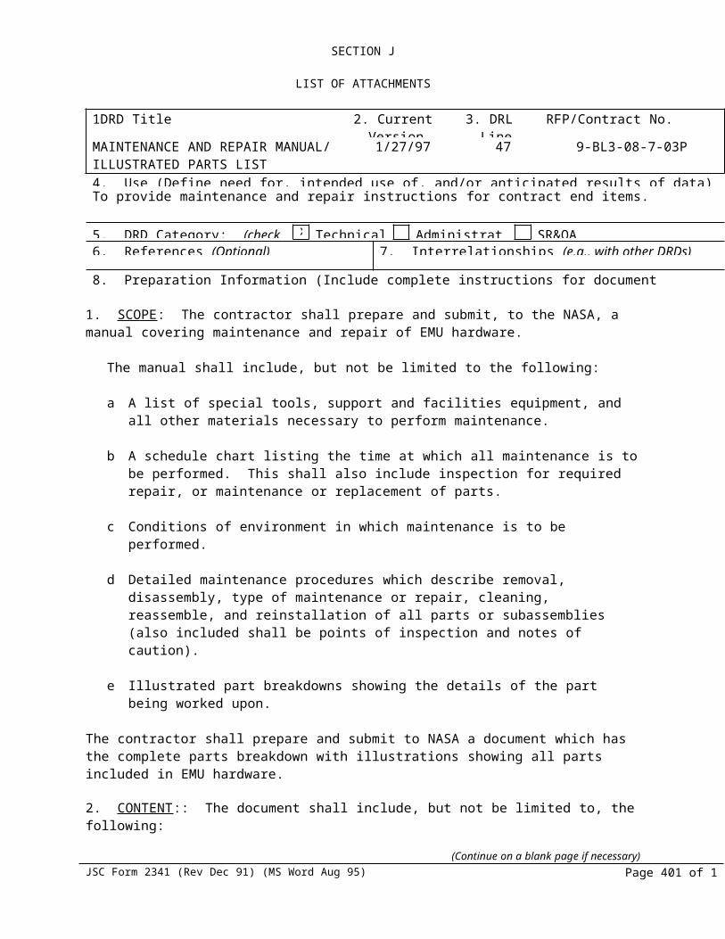
SECTION J-5
PROGRAM PROVISIONING WORK DESCRIPTION (PPWD)Phase VI TMGs 8 pr On or Before 9/30/02
Phase VI Bladders:Crewmember Size Date
DeliveredLu 6MA 4/28/00Spare 6BY 6/29/00Spare 6CR 7/26/00Spare 6GH 7/6/00Spare 6HD 7/26/00Spare 6HR 8/2/00Spare 6HM 10/2/00Spare 6US 1/18/01Spare 6CI 8/30/00Spare 6LA 8/30/00Spare 6WS 10/2/00Spare 6NO 10/2/00Spare 6TA 8/15/00Spare 6JG 10/31/00Spare 6LE 10/31/00Spare 6RS 10/25/00Phase VI Bladders Con’t:Crewmember Size Date
DeliveredParazynski 6PZ 11/6/00Voss (James) 6VS 1/10/01Burbank 6BB 2/8/01Spare 6RY 1/9/01Spare 6FN 12/8/00Spare 6TU 3/13/01Spare 6BC 2/27/01Spare 6CR 1/10/01Spare 6NO 1/18/01Spare 6HR 2/27/01Spare 6FO 5/2/01Spare 6WT 6/8/01Spare 6LA 6/29/01Spare 6MT 7/27/01Spare 6WS 7/27/01Thomas, A. 6TS 9/8/01Nicollier 6NI 9/8/01Smith 6SM 9/15/01Newman 6NM 1/12/02Bowersox 6BX 4/12/02Spare 6MT 5/28/02
DESCRIPTIONQTY DELIVERY DATEPhase VI Bladders 7 pr On or Before 9/30/02
4000 Series Gloves:Crewmember Size Voltage Date
DeliveredTMGs
(Continue on a blank page if necessary)JSC Form 2341 (Rev Dec 91) (MS Word Aug 95) Page 401 of 1

SECTION J-5
PROGRAM PROVISIONING WORK DESCRIPTION (PPWD)Barry ZG 3 3/31/99Malenchenko ZE 3 9/3/99Wisoff ZA 3 11/26/99Voss (James) ZH 3 3/10/00Horowitz ZG 3 3/10/00
GlovesWilliams ZF 3 9/3/99Lopez-Alegria ZG 3 11/26/99
Ref. SA 380Deferral Mod.
(Reference SA 352, Phase VI Implementation)
The following Quantities are revised:
FROM: FY 02
PVU Gloves 9 8Flight Gloves 52TMGs 44
Bladders 10
TO:FY 02
PVU Gloves 6 8Flight Gloves 38TMGs 42Bladders 8
Ref.: SA 363
This change reflects an equitable adjustment for effort associated with scrapping Protective Visor S/N 246. This Protective Visor was damaged during the coating process, which occurred on January 18, 2001 while being performed at Goddard Space Flight Center (GSFC).
SA 377N=124. SECTION J-6 Hardware Quantities and Delivery Schedule:
Add the following hardware:
ON OR BEFORE
(Continue on a blank page if necessary)JSC Form 2341 (Rev Dec 91) (MS Word Aug 95) Page 402 of 1

SECTION J-5
PROGRAM PROVISIONING WORK DESCRIPTION (PPWD)
ITEM PART NO.
DESCRIPTIONQTY
DELIVERY DATE
132 SV767793-7 Feedwater Supply Pressure Sensor 7 Shipped
153* SV789153-6ORU Kit consists of:SV823046-1 (Qty. 1)SV823046-2 (Qty. 1)AN565BC6H2 (Qty. 6)
Caution and Warning Harness 1 kit Shipped
176 SV821918-1 Filter, Water Inlet 2 Shipped314 SV787027-3 DCM Purge Valve 2
1ShippedShipped
(Continue on a blank page if necessary)JSC Form 2341 (Rev Dec 91) (MS Word Aug 95) Page 403 of 1

SECTION J
LIST OF ATTACHMENTS
SECTION J-7
HARDWARE REFURBISHMENT (LIFE EXTENSION)QUANTITIES AND SCHEDULES*
This attachment sets forth the delivery schedules for the contract end items to be refurbished against the requirements of Statement of Work, Section C:
Description Part Number ItemQTYFY 98
QTYFY99
QTYFY 00
QTYFY 01
QTYFY 02
Primary Pressure Control Module
SV778873-14 113 0 Ref. SA 193
0 Ref. SA 193 2 Ref. SA 193 1 Ref. SA 193
Shear Plate Assembly SV778540-49 115 2Check Valve and Vent Flow Sensor
SV771836-29 121 1
Fan/Separator/Pump Assembly
SV787994-12 123 2 2
Sublimator SV805280-4 140 0 Ref. SA 193
1 2 Ref. SA 193
Electronic Assembly SV792291-27 350 1 2 1Oxygen Filter and Orifice SV778504-2 420 2 2 2Airlock Adapter Plate SV767680-04-
00470 (2) 10/27/00*
(Ref. SA 204)(1)1/22/01*(Ref. SA 204)
Fleet Leader S/N 1006 shall be delivered 75 days after receipt of TD from NASA (Ref. SA 204)*GFE Shall be provided (from USA) 12 weeks in advance. (Ref. SA 204) All deliveries shall be “on or before” within fiscal year spending constraints.
Ref. SA 72Description Part Number Item Quantity Delivery
Dual Mode Relief Valves SV785844-16 120 2 9/30/99 Dual Mode Relief Valves SV785844-16 120 1 9/30/00
Delivery of the following hardware is contingent upon receipt (GFE from USA) of three (3) EMU item 120s (SV785844-12) with two (2) units in FY ’98 and one (1) unit in FY ’99.
Ref. SA 329SOP Regulator and Assemblies
Description P/N Qty Deliver on or before

SECTION J-5
PROGRAM PROVISIONING WORK DESCRIPTION (PPWD)
Retrofit Cold Traps SVSK125623 4 ea USA 03/24/02Retrofit Cold Traps SVSK125623 4 ea Bonded Stores 03/24/02SOP (clean only)* (S/N 1015)
SV799045 1 ea USA 11/30/01
SOP (clean only)*(S/N 1014)
SV799045 1 ea USA 02/15/02
SOP (clean only) *(S/N 1016, 1011, 1018, 1003, 1006, 1009, 1010, 1007, 1013, 1008, 1017)
SV799045 11 ea USA 10/01/01
Shear plates (clean and reassemble) S/Ns 004 & 012
SV778540 2 ea CRM Flight Stores (HS) 012 – 09/28/01USA 004 – 06/22/02
O2 Regulators (clean & reassemble)(S/Ns 114 & 115)
SV778873 2 ea These items will be included in the Shear plates above
Cold Traps (design & production)
SVSK125623 8 ea 10/1/01
Cryostats (procurement) TBD 13 ea Bonded Stores 10/30/01Flush Cart (procurement & design)
N/A 1 ea This item will be complete when all material has been received and accepted at HSSSI/Windsor Locks – 08/30/02
PLSS Regulator (S/N 107) Refurbish
SV778873 1ea This item will be delivered under the fleet leader evaluation task.
SOP Regulator (S/N 119) (Clean Only)
SV799042 1 ea CRM Flight Stores (HS) 12/31/01
* Validation of SOP cleanliness after field use, by removing a unit from field and inspecting and cleaning, is not included in this Supplemental Agreement.
SA 377N=12SECTION J-7 Hardware Refurbishment Schedule:
ITEM NO PART NO. DESCRIPTION
MAINTENANCE DESCRIPTION
QTY
GFE RECEIPT
DATE FROM USA*
ON OR BEFORE DELIVERY DATE
115 SV824133 Shear Plate Assembly
20 to 30 Year Life Extension Refurbishment
1 Received 09/30/02
420 SV778504 Filter Assembly, Oxygen and Orifice
15 to 25 Year Life Extension Refurbishment
22
Received06/01/02
05/30/0209/30/02
113 SV778873 Primary O2 Pressure Regulator
20 to 30 Year Life Extension Refurbishment
1
See Note (1) See Note (1)
(Continue on a blank page if necessary)JSC Form 2341 (Rev Dec 91) (MS Word Aug 95) Page 405 of 1

SECTION J-8
LIST OF ATTACHMENTS
HARDWARE PROVISIONING LIST
ITEM DESCRIPTION PART NUMBER
100 PRIMARY LIFE SUPPORT SUBSYSTEM (PLSS) SV799100 (S/AD)111 PRIMARY OXYGEN BOTTLE SV778895,SV784099112 PRIMARY OXYGEN PRESSURE SENSOR SV778528113 PRIMARY PRESSURE CONTROL MODULE SV778873113A CHECK VALVE SV778873113B RESTRICTION (FLOW) SV778873113C SHUTOFF VALVE SV778873113D SUIT PRESSURE REGULATOR SV778873113E WATER TANK PRESSURE REGULATOR SV778873114 PRESSURE SUIT SENSOR (psid) SV767788115 SHEAR PLATE ASSEMBLY SV778540116 EVA POSITION SWITCH SV789111120 DUAL MODE RELIEF VALVE SV785844120A BLEED ORIFICE SV785844120B DUAL MODE RELIEF VALVE SV785844120C FEEDWATER CHECK VALVE SV785844120D FLOW RESTRICTOR UNIT SV792686121 CHECK VALVE AND VENT FLOW SENSOR SV771836122 CARBON DIOXIDE TRANSDUCER SV809286123 FAN/SEPARATOR/PUMP ASSEMBLY SV787994123A FAN SV787994123B ROTARY WATER SEPARATOR SV787994123C WATER PUMP SV772277123D BRUSHLESS MOTOR SV787993125 PITOT ACTUATED VALVE SV769480127/128 CHECK VALVE SV784996127 PUMP INLET FILTER SV805180128 CHECK VALVE AND HOUSING SV767699131 PRIMARY WATER TANK #1 SV769592132 FEEDWATER SUPPLY PRESSURE SENSOR SV767793-1,-5,-7134 CONDENSATE WATER RELIEF VALVE SV769403135 FEEDWATER RELIEF VALVE SV769404136 FEEDWATER PRESSURE REGULATOR SV792528137 FEEDWATER SHUTOFF VALVE SV767660-4,-5,-9,-10138 FEEDWATER PRESSURE SENSOR SV767793-2,-6,-8139/140 SUBLIMATOR AND HARNESS SV805280139 TEMPERATURE SENSOR HARNESS SV792503140 SUBLIMATOR SV805279141 GAS TRAP SV805257-1142 WATER RELIEF VALVE SV769405143 WATER CHECK VALVE SV769406145 RELIEF VALVE AND ORIFICE SV785860146 POSITIVE PRESSURE RELIEF VALVE SV787036147 NEGATIVE PRESSURE RELIEF VALVE SV785927148 RESERVE WATER TANK SV769592150 CAUTION AND WARNING SYSTEM SV785970151 ELECTRICAL POWER HARNESS SV789151152 ELECTRICAL SIGNAL HARNESS SV789152
153 CAUTION AND WARNING HARNESS SV789153156 REAL TIME DATA SYSTEM HARNESS SV789134

SECTION J-5
PROGRAM PROVISIONING WORK DESCRIPTION (PPWD)ITEM DESCRIPTION PART NUMBER161 PLSS/SOP THERMAL COVER SV799043162 PRIMARY WATER TANK #2 SV769592171/172 COOLANT ISOLATION VALVE ASSEMBLY SV784998171 WATER SHUTOFF VALVE SV784982172 COOLANT RELIEF VALVE SV784985174 SIGNAL CONDITIONER (RTDS) SV791230101 COMMUNICATIONS CARRIER ASSY (CCA) 0101-10001 (S/AD)102 HARD UPPER TORSO (HUT) 0102-10002 (S/AD)602 HARD TORSO SHELL (HTS)
EXTRA SMALL SV772325 SMALL SV772335 MEDIUM SV772345 LARGE SV772375 EXTRA LARGE SV772385
103 ARM ASSEMBLY 0103-10003 (S/AD) UPPER ARM ASSEMBLY 0103-84025/
0103-810172 LOWER ARM ASSEMBLY 0103-84026 LOWER ARM ASSEMBLY 0103-89753103 ARM ASSEMBLY 0103-110103 (S/AD) UPPER ARM ASSEMBLY 0103-29958 LOWER ARM ASSEMBLY 0103-21052104 LOWER TORSO ASSEMBLY 0104-10004 (S/AD) WAIST RESTRAINT/BLADDER ASSEMBLY 0104-82347 WAIST RESTRAINT/BLADDER ASSEMBLY 0104-84402 WAIST RESTRAINT & BLADDER ASSY 0104-84811 WAIST TMG 0104-82692 WAIST TMG 0104-84386 WAIST TMG 0104-84905 TROUSER 0104-84027 BOOT ASSEMBLY 0104-84028 BOOT SIZING INSERT 0104-82664 BODY SEAL CLOSURE 9785,9787,9789,9791 WAIST BEARING 9698,9699,9714 WAIST BEARING 10043,10058,10057104 LOWER TORSO ASSEMBLY 0104-110104 (S/AD) BOOT SIZING INSERT 0104-89951 BOOT ASSEMBLY 0104-210895 LEG ASSEMBLY 0104-210575 BRIEF/WAIST ASSEMBLY 0104-210605105 HELMET 0105-10005 (S/AD)106 GLOVE ASSEMBLY S/N 1000 SERIES 0106-10006 (S/AD)106 MODIFIED GLOVE ASSEMBLY
S/N 3000 SERIES0106-16000 (S/AD)
106 4000 GLOVE ASSEMBLY 0106-19010 (S/AD)107 GLOVE ASSEMBLY S/N 5000 SERIES 0106110001(S/AD)
107 LIQUID COOLING & VENTILATION GARMENT (LCVG)
0107-10007 (S/AD)
BOOT LEG VENT DUCT (BLVD) 0107-81057 GARMENT ASSEMBLY 0107-84029108 EXTRAVEHICULAR VISOR ASSY (EVVA) 0108-10008 (S/AD)110 IN-SUIT DRINK BAG (IDB) 0110-10010 (S/AD)
(Continue on a blank page if necessary)JSC Form 2341 (Rev Dec 91) (MS Word Aug 95) Page 407 of 1

SECTION J-5
PROGRAM PROVISIONING WORK DESCRIPTION (PPWD)ITEM DESCRIPTION PART NUMBER200 SECONDARY OXYGEN PACK (SOP) SV799045 (S/AD)210 SECONDARY OXYGEN BOTTLE SV778880,SV809816213 SECONDARY OXYGEN PRESSURE
CONTROL MODULESV799042
213B O2 PRESSURE REGULATOR (1ST STAGE) SV799042213D 02 PRESSURE REGULATOR (2ND STAGE) SV799042213E PRESSURE GAGE SV799042213F HIGH PRESSURE FILL CONNECTOR SV799042213G INTERSTAGE PRESSURE GUAGE SV799042215 PRESSURE TRANSDUCER & CONNECTOR SV785018300 DISPLAY & CONTROLS MODULE (DCM)
S/N 2000 SERIESSV792294 (S/AD)
350 ELECTRONIC ASSEMBLY SV792291351 LCD MODULE SV792526384 DCM THERMAL COVER SV771987-11386 INTERNAL WIRING ASSEMBLY SV792293360 VOLUME CONTROL SV767784361 DISPLAY INTENSITY CONTROL SV767785362 EVC MODE SELECTOR SWITCH SV767786364 POWER MODE SWITCH SV778596365 PUSH-TO-TALK SWITCH SV767794366 FAN SWITCH SV771887-2367 FEEDWATER VALVE SWITCH SV767795-2368 CAUTION & WARNING SYSTEM
SWITCHSV767792
385 OXYGEN, WATER MANIFOLD ASSEMBLY SV779301311 SUIT PRESSURE GUAGE SV767706314 PURGE VALVE SV787027321 TEMPERATURE CONTROL VALVE SV789693387 EXTERNAL WIRING ASSEMBLY SV774161330 COMMON MULTIPLE CONNECTOR SV778872-17400 SERVICE AND COOLING UMBILICAL (SCU) SV767730 (S/AD)410 COMMON MULTIPLE CONNECTOR SV778872-18411 OXYGEN HIGH PRESSURE LINE SV778865412 WATER LINE SV771722412A POTABLE WATER LINE SV771722412B COOLING WATER IN-LINE SV771722412C COOLING WATER OUT-LINE SV771722416 BACTERIA FILTER SV767709418 CONDENSATE WATER REGULATOR SV771717419 WATER SUPPLY PRESSURE REGULATOR SV772190420 OXYGEN FILTER AND ORIFICE SV778504423 BACTERIA CARTRIDGE SV784967424 POTABLE WATER FILTER SV803691,SV803695
425 SCU ELECTRICAL HARNESS SV771763414 VEHICLE ELECTRICAL CONNECTOR SV764255-24426 CONNECTOR BACKSHELL SV787944427 SCU ELECTRICAL CONNECTOR SV785003428 SHEATH ASSEMBLY SV771749415 TETHER HOOK SV771749429 TETHER SHACKLE SV772134440 EMU ELECTRICAL HARNESS (EEH) SV767690 (S/AD)470 AIRLOCK ADAPTER PLATE (AAP) SV767680 (S/AD)480 CONTAMINANT CONTROL CARTRIDGE (CCC) SV792600 (S/AD)
(Continue on a blank page if necessary)JSC Form 2341 (Rev Dec 91) (MS Word Aug 95) Page 408 of 1

SECTION J-5
PROGRAM PROVISIONING WORK DESCRIPTION (PPWD)ITEM DESCRIPTION PART NUMBER
S/N 2000 SERIES490 BATTERY SV767789 (S/AD)491 BENDS TREATMENT ADAPTER (BTA) SV792740 (S/AD)492 PRESSURE GAUGE SV792695493 PRESSURE RELIEF VALVE SV792696495 SOP CHECKOUT FIXTURE (SCOF) SV799099 (S/AD)497 HELMET HOLDING FIXTURE SV809335498 EMU UMBILICAL SV819500
(Continue on a blank page if necessary)JSC Form 2341 (Rev Dec 91) (MS Word Aug 95) Page 409 of 1

SECTION J
LIST OF ATTACHMENTS
SECTION J-9
SAFETY AND HEALTH PLAN
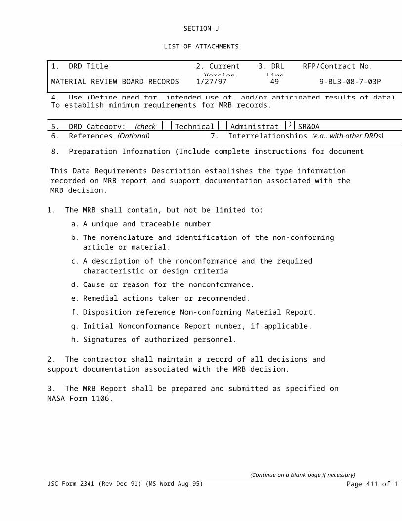
SECTION J
LIST OF ATTACHMENTS
SECTION J-10
GOVERNMENT FURNISHED PROPERTY
The Government Physical Inventory Report dated February 2, 1997(as revised) is hereby incorporated into the contract by reference.

SECTION J
LIST OF ATTACHMENTS
SECTION J-11
INSTALLATION PROVIDED PROPERTY
The JSC Custodian Account Quarterly Report dated 7/1/97 is hereby incorporated into the contract by reference.
(Continue on a blank page if necessary)JSC Form 2341 (Rev Dec 91) (MS Word Aug 95) Page 412 of 1

SECTION J
LIST OF ATTACHMENTSSECTION J-12
APPLICABLE DOCUMENTS
The following documents, of the exact issue shown, including documents referenced therein, form a part of this contract to the extent specified herein. In the event of conflict between these documents and any other provisions of this contract, the latter shall govern.
Note: All materials, parts, and processes shall conform to the requirements of SE-R-0006 or shall utilize specifications which satisfy SE-R-0006.
1.0 SPECIFICATIONS
1.1 NASA
SC-E-0006 MANNED SPACEFLIGHT EV/IV ACTIVITYDECEMBER 1,1972 SUPPORT EQUIPMENT, FUNCTIONAL DESIGN
REQUIREMENTS
JSC 26626A EXTRAVEHICULAR ACTIVITY (EVA) MAY 22, 1995 HARDWARE GENERIC DESCRIPTION
REQUIREMENTS DOCUMENT
SE-F-OO44B FILTERS. WIRE CLOTH TYPE, GENERALCHANGE 8, MAY 11,1987 SPECIFICATION
SE-G-OO20A LEAKAGE MEASUREMENT OF HELIUM ANDMARCH 17, 1972 NITROGEN TEST GASES
SE-R-OOO6B GENERAL SPECIFICATION, NASA JSCMARCH 29, 1976 REQUIREMENTS FOR MATERIALS AND
PROCESSES
SE-S-OO73D SPECIFICATION, NSTS FLUID PROCUREMENT CHANGE 33, CONTROL AND USE
MAY 11, 1987
SL-E-0002, REVISION B NSTS SPECIFICATION, ELECTROMAGNETIC CHANGE 13, MAY 11, 1987 CHARACTERISTICS REQUIREMENTS FORCHANGE 14, DECEMBER1, EQUIPMENT1987
APPLICABLE DOCUMENTS - Continued

SECTION J
LIST OF ATTACHMENTS
SN-C-0005 SPECIFICATION, CONTAMINATION CONTROL 1974 REQUIREMENTS FOR SPACE SHUTTLE
PROGRAM
SP-R-OO22A GENERAL SPECIFICATION VACUUM STABILITY REQUIREMENTS OF
POLYMERIC MATERIAL FOR SPACECRAFT APPLICATION
SP-T-OO23B ENVIRONMENTAL ACCEPTANCE TESTINGSEPTEMBER 1975 SPECIFICATION
ST-R-00001 SCAN MISS TEST OR X-RAY
1.2 MILITARY
DOD-D-lOOOA DRAWINGS. ENGINEERING AND ASSOCIATED AMENDMENT 3, LISTSMAY 13, 1983
MIL-A-8625D ANODIC COATINGS. FOR ALUMINUM ANDJUNE 30, 1985 ALUMINUM ALLOYS
MIL-B-5087B BONDING. ELECTRICAL AND LIGHTING AMENDMENT 3 PROTECTION FOR AEROSPACE SYSTEMS
DECEMBER 24, 1984
MIL-C-5541B CHEMICAL CONVERSION COATINGS ON ALUMINUM AND ALUMINUM ALLOYS
MIL-STD-2175 CASTINGS. CLASSIFICATION ANDOCTOBER 12, 1984 INSPECTION OF
MIL-I-26860B(2) INDICATOR, HUMIDITY PLUG, COLOR AMENDMENT 2 CHANGEAPRIL 25, 1974
MIL-L-38169, LENSES, GOGGLES, AND VISOR HELMETAMENDMENT 5 OPTICAL CHARACTERISTICS - CONTROLLED AUGUST 4, 1969 BY WRIGHT-PATTERSON AFB
(Continue on a blank page if necessary)JSC Form 2341 (Rev Dec 91) (MS Word Aug 95) Page 414 of 1

SECTION J
LIST OF ATTACHMENTSAPPLICABLE DOCUMENTS - Continued
MIL-M-38510A MILITARY SPECIFICATION MICROCIRCUITS GENERAL SPECIFICATION FOR
MIL-O-27210E, OXYGEN, AVIATORS BREATHING, LIQUID AND AMENDMENT 2 GASJANUARY 20, 1984
MIL-P-6906B, PLATES, IDENTIFICATION, AIRCRAFTNOTICE 2MARCH 10, 1981
MIL-S-7742B SCREW THREADS STANDARD, OPTIMUM SEPTEMBER 1, 1972 SELECTED SERIES
MIL-S-19500A SEMICONDUCTOR DEVICES, GENERALSPECIFICATION FOR
1.3 OTHER
MJ070-0001-1C ORBITER VEHICLE END ITEM JANUARY 3, 1983 SPECIFICATION FOR THE SPACE SHUTTLECHANGE 30 - NOV. 30, I987 SYSTEM, PART 1, DESIGN AND CHANGE 42 - JULY 11, 1986 PERFORMANCE REQUIREMENTS
STANDARDS
2.0 STANDARDS
2.1 NASAJSCM 1700 SAFETY MANUALNSTS 08080-1 MANNED SPACECRAFT DESIGN CRITERIA JUNE 1992 AND STANDARDS
2.2 FEDERAL
FED-STD-406A PLASTIC: METHODS OF TESTINGJANUARY 4, 1982
APPLICABLE DOCUMENTS - Continued
2.3 MILITARY(Continue on a blank page if necessary)
JSC Form 2341 (Rev Dec 91) (MS Word Aug 95) Page 415 of 1
SECTION J
LIST OF ATTACHMENTS
DOD-STD-100 C ENGINEERING DRAWING PRACTICESMIL-STD-129J MARKING FOR SHIPMENT AND STORAGENOVEMBER 6, 1986
MIL-STD-130F IDENTIFICATION AND MARKING OF U.S.MAY 1, 1986 MILITARY PROPERTY
MIL-STD-202F TEST METHODS FOR ELECTRONIC ANDNOTICE 8 ELECTRICAL COMPONENT PARTSAPRIL 11, 1986
MIL-STD-462 EMI CHARACTERISTIC MEASUREMENT OFAUGUST 4. 1986
MIL-STD-463A DEFINITION AND SYSTEM OF UNITS EMIJUNE 1, 1977 TECHNOLOGY
MIL-STD-750C TEST METHODS FOR SEMICONDUCTOR FEBRUARY 23. 1983 DEVICES
MIL-STD-810D ENVIRONMENTAL TEST METHODSNOTICE 1JULY 31, 1986
MIL-STD-883A TEST METHODS AND PROCEDURES FORMICROELECTRONICS
MIL-STD-1247B MARKINGS, FUNCTIONS & HAZARDDECEMBER 20, 1968 DESIGNATIONS OF HOSE, PIPE. AND
TUBE LINES
MIL-STD-1472C HUMAN ENGINEERING DESIGN CRITERIA FORNOTICE 3 MILITARY SYSTEMS, EQUIPMENT ANDMARCH 17, 1987 FACILITIES
MS-33540, REVISION J SAFETY WIRING AND COTTER PINNINGJULY 23, 1986
APPLICABLE DOCUMENTS - Continued
3.0 OTHER
(Continue on a blank page if necessary)JSC Form 2341 (Rev Dec 91) (MS Word Aug 95) Page 416 of 1
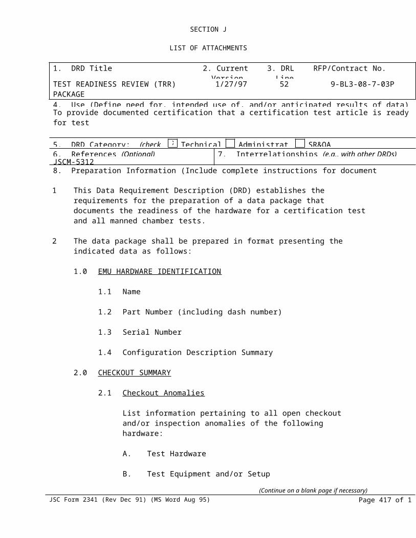
SECTION J
LIST OF ATTACHMENTS3.1 NASA
CSD-SH-021 REV. D CSD SPACE SHUTTLE PROGRAM CREW JSC 06997 RELATED GFE CONTRACTOR'S AUGUST 14, 1975 CONFIGURATION MANAGEMENT MANUAL
CSE-SH-028 DESIGN ENVIRONMENTS FOR CSD-JSC 08708 PROVIDED SPACE SHUTTLE HARDWARESEPTEMBER 11, 1975
ICD HDA04-SVHS 439-31, PLSS-EVCS ELECTRICAL FUNCTIONALCHANGE D, MAY 11, 1970 INTERFACE
NSTS-07700 -10-MVP-01 SHUTTLE MASTER VERIFICATION REVISIONREVISION D PLAN CHANGE 58
NHB-5300.4 (3A-1) JSC SUPPLEMENT TO NHB 5300.4 (3A)DECEMBER 1976 REQUIREMENTS FOR SOLDERED
ELECTRICAL CONNECTIONS
JSC-09604 MATERIALS SELECTION LIST FOR SPACEHARDWARE SYSTEMS
JSC-17057 GFE LIMITED LIFE CYCLE TIME/AGE LIFEREVISION 1, ITEMS REQUIREMENTS SEPTEMBER 1985
NHB 5150.7E PERFORMANCE EVALUATION
NHB 600.1B REQUIREMENTS FOR PACKAGING, HANDLINGJUNE 1976 AND TRANSPORTATION FOR AERONAUTICAL
AND SPACE SYSTEMS EQUIPMENT AND COMPONENTS
NHB 8060.1 FLAMMABILITY, ODOR, AND OFFGASSINGSEPTEMBER 1981 REQUIREMENTS AND TEST PROCEDURES
FOR MATERIALS IN ENVIRONMENTS THAT SUPPORT COMBUSTION
APPLICABLE DOCUMENTS - Continued
NHB 9501.2B PROCEDURES FOR CONTRACTOR (Continue on a blank page if necessary)
JSC Form 2341 (Rev Dec 91) (MS Word Aug 95) Page 417 of 1
SECTION J
LIST OF ATTACHMENTSFEBRUARY 1985 REPORTING OF CORRELATED COST
AND PERFORMANCE DATA
NSTS 07700, VOL. X, REV.L SPACE SHUTTLE FLIGHT & GROUND CHANGE 230 SYSTEMS SPECIFICATION NSTS 22206, MARCH 1996 REQUIREMENTS OF PREPARATIONREV. D, CHANGE 26 AND APPROVAL OF FAILURE MODES AND
EFFECTS ANALYSIS AND CRITICAL ITEMS LIST SPECIFICATION
NSTS 22254 METHODS FOR CONDUCT OF SPACE JUNE 1996, REV B, SHUTTLE PROGRAM HAZARD ANALYSISCHANGE 5
MSFC-SPEC-522A DESIGN CRITERIA FOR CONTROLLING STRESS CORROSION CRACKING
MSFC-HDBK-527 MATERIALS SELECTION LIST FOR SPACEHARDWARE SYSTEMS
3.2 MILITARY
AMRL TECHNICAL REPORT 70-5 ANTHROPOMETRY OF AIR FORCE APRIL 1972 WOMEN
WADC TECHNICAL REPORT 52-321 ANTHROPOMETRY OF USAF SEPTEMBER 1954 FLYING PERSONNEL1950
3.3 INDUSTRY
ANSI B46.1-62, CHANGE 2 SURFACE TEXTURE, SURFACE JANUARY 1978 ROUGHNESS, WAVINESS AND LAY
ANSI/ASQC Q9001-1994 QUALITY SYSTEM - MODEL FOR QUALITY ASSURANCE WITH DESIGN,
DEVELOPMENT, PRODUCTION, INSTALLATION, AND SERVICING
(Continue on a blank page if necessary)JSC Form 2341 (Rev Dec 91) (MS Word Aug 95) Page 418 of 1

SECTION J
LIST OF ATTACHMENTS

Section J-13Carry-Over Effort
Ref. SA 22Section J-13 is deleted in its entirety (with exception of SAs 35, 37 & 38) and thefollowing substituted herein:
I. IMPLEMENTATION EVA SSA ENHANCEMENTS
1. The contractor shall provide the following SSA hardware components in accordance with the unit pricing and delivery schedules indicated below: Unit Extended Delivery Item Quantity Price Price Date ARO*
Dual Seal Scye Bearings (w/Clamp Ring)P/N 10134-02 (w/23456) 4 pair $63,105 $252,420 3/12/98
Enhanced Lower ArmP/N 0103-210152 -XX-XX 16 pair $74,838 $1,197,408 2/12/99
Enhanced Shoulder P/N 0103-810576-01-04 4 pair $24,272 $97,088 2/12/99
Arm Sizing Rings P/N 10146-03 4 pair $16,183 $64,732 3/12/98
16" Enhanced Brief P/N 0104-810598-03 18 each $39,914 $718,452 2/12/99
16" Dual Seal Waist Bearing P/N 10057-03 5 each $69,903 $349,515 5/12/98
Dual Seal Wrist Bearing P/N 10088-02 1.5 pair $32,364 $48,546 3/12/98
Enhanced LegsP/N 0104-210575-XX-XX 14 pair $53,167 $744,338 2/12/99
Waist Restraint, Bladder & TMGP/N 0104-82347-XX-XX (Rest/Bladd
Unit Extended Delivery Item Quantity Price Price Date ARO*
P/N 0104-82692-
(Continue on a blank page if necessary)JSC Form 2341 (Rev Dec 91) (MS Word Aug 95) Page 420 of 1

Section J-13Carry-Over Effort
XX-XX (TMG) 23 each $12,046 $433,656 2/12/99(13 deleted per CCO 230)
Garment, LCVGP/N 0107-84029-18-XX 13 each $45,806 $595,478 2/12/99
BLVD, LCVGP/N 0107-81057-XX-XX-XX 9 pair $8,090 $72,810 2/12/99
Helmet (Less CPV)P/N 0105-10005-10 4 each $72,818 $291,272 6/12/98
Boot, Small(less Boot Discon.)P/N 0104-89652-07/08 2 pair $32,368 $64,736 2/12/99
Boot, Large(less Boot Discon.)P/N 0104-89652-05/06 4 pair $30,745 $122,980 2/12/99
Boot Sizing Rings P/N 10157-02, P/N 10202-02,P/N 10203-02 13 each $8,630 $112,190 3/12/98
Boot DisconnectsP/N 10154-02 5 pair $19,417 $97,085 3/12/98
2. Clause B.3 - Estimated Cost and Fee Arrangement is amended to reflect the cost and fee adjustments indicated below:
Negotiated Value NAS 9-97150 NAS 9-17873
Firm-Fixed-Price $ 6,472,527 $ 5,262,706 $ 1,200,0$ 1,209,821
On or Before Months After Receipt of Order
Ref. SA 181
The contractor shall make the configuration change to the Enhanced Shoulder, which eliminates a potential leak path through the shoulder scye bearing bladder flange. This change involves the application of Solu-bond adhesive to the flange edge to seal the leak path. This change will be incorporated in all new builds and can be incorporated into existing units, via depot maintenance at ILC/Dover, as necessary to maintain within specification leakage performance. In addition, an Enhanced Shoulder drawing and a
(Continue on a blank page if necessary)JSC Form 2341 (Rev Dec 91) (MS Word Aug 95) Page 421 of 1

Section J-13Carry-Over Effort
RPHG Enhanced Shoulder drawing shall be created to allow configuration control of this component.
II. PLANAR HARD UPPER TORSO PHASE III EFFORT
A. Description/Specifications/Work Statement: The purpose of this section is to define the requirements that must be met by the Extravehicular Mobility Unit (EMU) System contractor in the accomplishment of the Phase III Planar Hard Upper Torsos (HUT) effort. The Phase I and Phase II Planar HUT effort encompassed the design, development, manufacture, certification, and incorporation of the On-Orbit Replacement Unit (ORU) concept into the Planar HUT. The objective of Phase III Planar HUT effort is to provide Flight and Weightless Environment Training Facility (WETF) Neutral Buoyancy Lab (NBL) production units to support the Space Shuttle and International Space Station Programs.
The first Planar HUT production units shall be delivered to the NASA JSC Crew and Thermal System Division with the balance being delivered to the flight equipment processing contractor. Class I Planar HUT units shall be manufactured with all new hardware components. Class III Planar HUT units shall be manufactured using both new hardware components and GFE hardware obtained from existing Class III pivoted HUT units. Planar HUT units will be produced in two sizes - medium and large. The Planar HUT delivery schedule (F-1) calls for the delivery of HUT units beginning in GFY 1996 and continuing through GFY 2000.
B. Program Description/Requirements: The contractor shall provide all necessary resources to fabricate, assemble, acceptance test, and deliver Planar Hard Upper Torso (HUT) units in accordance with Specification/Assembly Drawing 0102-110102 Parts I & II. Planar HUT production units shall consist of 18 each Class I and 10 each Class III configurations as indicated in F-1. Planar HUT units shall be produced in two sizes -11 each medium and 17 each large .
The contractor shall accomplish predelivery acceptance testing on each HUT unit in accordance with Specification/Assembly Drawing 0102-110102 Parts I & II. The predelivery test is a functional test and inspection to verify that each Planar Hut unit is produced in accordance with the applicable specification and meets specific requirements for workmanship and performance. Class III hardware shall be manufactured in accordance with Hamilton Standard EMU Procedure 041A. The following GFE hardware will be provided to the contractor from existing Class I and Class III, Pivoted HUTs. Class I Pivoted HUTs will be downgraded to Class III status in the field prior to delivery to the contractor. This hardware will be used to build the 10 Class III Planar HUT units. GFE hardware components will be removed from Class III
(Continue on a blank page if necessary)JSC Form 2341 (Rev Dec 91) (MS Word Aug 95) Page 422 of 1

Section J-13Carry-Over Effort
Pivoted HUTs by the contractor and, if serviceable, will be incorporated into the Class III Planar HUTs. Additional GFE hardware components will be provided to the contractor to replace non-serviceable hardware components. All GFE hardware will be provided to the contractor 3 months prior to the delivery of each unit.
Government Furnished Property Description Part Number* Quantity
Helmet to Suit Disconnect (Neck Ring) A/L 9357-XX 10 Helmet Vent Seal Assembly A/L 9715-03 10 16” HUT Side Body Seal Closure (BSC) A/L 9786-XX 10 Water Line and Vent Tube Assembly 0102-82437-XX 10 Hut Side Multiple Water Connector A/L 9694-XX 10
*Dash numbers vary depending on which pivoted HUT is used.The contractor shall provide the following spare hardware components to maintain the Planar HUT mission probability of sufficiency at 90 percent: Spares Allocation Requirements
Description Part Number* Quantity
16” HUT Side Body Seal Closure A/L 9786-XX 7Helmet to Suit Disconnect (Neckring) A/L 9357-XX 7Water Line Vent Tube Assembly 0102-82437-XX 7HUT Side Multiple Water Connector A/L 9694-XX 7Helmet Vent Seal Assemblies A/L 9715-03 7
*Dash numbers vary depending on which pivoted HUT is used.
Description Part Number Quantity
Medium Size TMG 0102-811395-01-01 3Large Size TMG 0102-811395-01-02 4Medium Hard Torso Shell SV810002 3
Large Hard Torso Shell SV810003 4”
C. Planar Hut Phase III Delivery Schedule: Spares Allocation Requirements
Description Part Number* Quantity
16” HUT Side Body Seal Closure A/L 9786-XX 7Helmet to Suit Disconnect (Neckring) A/L 9357-XX 7Water Line Vent Tube Assembly 0102-82437-XX 7HUT Side Multiple Water Connector A/L 9694-XX 7Helmet Vent Seal Assemblies A/L 9715-03 7
(Continue on a blank page if necessary)JSC Form 2341 (Rev Dec 91) (MS Word Aug 95) Page 423 of 1

Section J-13Carry-Over Effort
*Dash numbers vary depending on which pivoted HUT is used.
Description Part Number Quantity
Medium Size TMG 0102-811395-01-01 3Large Size TMG 0102-811395-01-02 4Medium Hard Torso Shell SV810002 3
Large Hard Torso Shell SV810003 4”
GFY GFY GFY GFY GFYGFY SizePlanar HUTs 1996 1997 1998 1999 20002000 Total
Class I - Sizes - Large 0102-110102 - 2 - 2 1 1 5 -0 6 - Medium 0102-110102 - - 1 3 3 -0 6
Class III - Sizes
- Large 0102-110102 - 1 2 - 3 0 -0 3
- Medium 0102-110102 - - 2 1 1 -0 2
Totals - - 8 9 7 17
2. Cost Incentive Provision:
The fee payable under this provision for the Planar HUT Phase III effort as defined above shall be the target fee of $1,141,400 increased by $0.30 for every dollar that the total allowable cost is less than $16,637,000 or decreased by $0.30 for every dollar that the total allowable costs exceeds $16,637,000. In no event shall the incentive fee for Planar HUT Phase III be greater than $1,630,600 or less than $570,700.*Delivery of optional spares hardware, if option is exercised, shall be on or before September 30, 2000.
3. Clause B.3 - Estimated Cost and Fee Arrangement is amended to reflect the cost and fee adjustments indicated below:
Negotiated Value NAS 9-97150 NAS 9-17873
Cost $ 16,637,000 $ 8,007,386TBD $ 8,629,614Incentive Fee $ 1,141,400 $ 549,355 $ 592,045
Total $ 17,778,400 $ 8,556,741 $ 9,221,659
E. Option Quantity: (Continue on a blank page if necessary)
JSC Form 2341 (Rev Dec 91) (MS Word Aug 95) Page 424 of 1

Section J-13Carry-Over Effort
B.11 Options for Increased Quantity - Planar HUT Phase III - The Government may require the delivery of 7 spare Planar HUT hardware components. The contracting officer may unilaterally exercise this option by issuance of a contract modification no later than March 1,1998. Should this option be exercised, the resultant contract will include all terms and conditions of the basic (NAS9-17873) contract as it exists immediately prior to the exercise of the option except for the following changes:
1. As negotiated:
Target cost for the 7 spare Planar HUT components shall be $4,159,000. The target fee shall be $285,400. The total CPIF shall be $4,444,400.
1. The fee payable under this provision for the Planar HUT Phase III option effort as defined in herein shall be the target fee of $1,426,800 increased by $0.30 for every dollar that the total allowable cost is less than $20,796,000 or decreased by $0.30 for every dollar that the total allowable costs exceeds $20,796,000. In no event shall the incentive fee for Planar HUT Phase III be greater than $2,038,300 or less than $713,400.
III. ISS ORU CONFIGURATION, DESIGN, DEVELOPMENT CERTIFICATION AND PRODUCTION
1. The contractor shall complete Phase I, including completion of the design layout, mockup manufacture, PDR, CDR, retrofit of SEMU/ORU mockup, flight (Level III) drawings, HS/JSC mockup evaluations, manufacture and test of Design Verification Hardware, and release of flight drawings. Phase II shall include the manufacturing and certification testing of one set of ORU EMU Hardware for confidence flight on STS-99. Delivery shall be on or before April, 1998.
2. Clause B.3 - Estimated Cost and Fee Arrangement is amended to reflect the cost and fee adjustments indicated below:
Negotiated Value NAS 9-97150 NAS 9-17873
Cost $ 4,300,000 $ 952,058 $ 3,347,942Fixed Fee $ 285,600 $ 63,236 $ 222,364
Total $ 4,585,600 $ 1,015,294 $ 3,570,306
IV. INCREASED CAPACITY BATTERY CERTIFICATION AND PRODUCTION
1. The contractor shall provide the following hardware in accordance with the following schedule:
P/N Quantity Delivery (Ref. SA 148)
(Continue on a blank page if necessary)JSC Form 2341 (Rev Dec 91) (MS Word Aug 95) Page 425 of 1

Section J-13Carry-Over Effort
Battery SV819600-00 6 12/31/99Battery SV819600-00 6 02/29/00Battery SV819600-00 6 04/30/00Battery SV819600-00 6 06/30/00
Certification Effort
32 Cycle / 6 mos 12/31/98425 Day Wet Life 06/30/99
* No useful life
2. Clause B.3 - Estimated Cost and Fee Arrangement is amended to reflect the cost and fee adjustments indicated below:
Negotiated Value NAS 9-97150 NAS 9-17873
Cost $ 1,485,000 $ 829,567 $ 655,433Fixed Fee $ 101,700 $ 56,813 $ 44,887
Total $ 1,586,700 $ 886,380 $ 700,320
V. EMU UMBILICAL CERTIFICATION AND PRODUCTION
Ref. SA 187The contractor shall make a change to the P1 Umbilical backshell which incorporates an oblong cable entry area that will support a larger radius (.080” - .090”) leading into the backshell cavity. This is a change from the current backshell which has a small radius (.010” min) which could result in cold-flow to the wire insulation and/or conductors over an extended period of time. The contractor shall also revise the crewlock wall temperature in the Umbilical S/AD Table IV, design note 16.24 and 16.28 and 16.28 from +34 deg. F to +50 deg. F and changes design note 16.24 to reference design note 16.28 for radiation sink temperature. These requirements now reflect those in the Umbilical Requirements Document. In addition, the contractor shall change the method of certifying design note 16.8, shock, ground environments from test and analysis to analysis only. The requirement to certify by test was initially assigned before the shipping container was designed. Since then a container was designed and manufactured that permits certification by analysis only.
The Umbilical deliveries are shown below:
Quantity Description Delivery to GFE Hardware GFE Delivery to NASA Hamilton Sunstrand*
(Continue on a blank page if necessary)JSC Form 2341 (Rev Dec 91) (MS Word Aug 95) Page 426 of 1

Section J-13Carry-Over Effort
2 Flight Umbilical 12/31/99 (2) Umbilical Connector Manifold By 6/30/99P/N SEG 39128293-301
1 Flight Umbilical 1/31/00 (1) Umbilical Connector Manifold By 7/31/99P/N SEG 39128293-301
1 Flight Umbilical 2/28/00 (1) Umbilical Connector Manifold By 8/31/99P/N SEG 39128293-301
*Delays in receipt of acceptable GFE hardware by dates listed in this table will impact deliveries to NASA
ref SA 166
Description Qty Delivery to NASA GFE Hardware GFE Delivery to H.S.
Flight Umbilical 1 11/30/99 (1) Umbilical Connector Manifold By 4/30/99P/N SEG 39128293-301
Flight Umbilical 1 12/31/99 (1) Umbilical Connector Manifold By 5/31/99P/N SEG39128293-301
Flight Umbilical 1 1/31/00 (1) Umbilical Connector Manifold By 6/30/99 P/N SEG 39128293-301
Flight Umbilical 1 2/28/00 (1) Umbilical Connector Manifold By 7/31/99 P/N SEG39128293-301
*Initial delivery of one Umbilical by 3 months after receipt of GFE hardware to support EMI and SSATA testing with upgrade to flight and delivery by 10/31/98 or 5 months after SSATA testing, whichever is later.
Hamilton Standard deliverables:
Item Qty P/N Delivery
Report detailing the evaluation of routing 1 TBD No NBL evaluation and crew-lock stowage provisions planned to complete
this activity. QLR XL-97-42 transmitted 7/3/97 documents final locations of Umbilical restraints.
DCM Multiple Connector modified with 1 TBD 1/31/98(Continue on a blank page if necessary)
JSC Form 2341 (Rev Dec 91) (MS Word Aug 95) Page 427 of 1

Section J-13Carry-Over Effort
6" electrical pigtail to be used in GSE
GFE deliveries to support Hamilton Standard deliveries:
Item Qty P/N Delivery
Umbilical half of UIA Multiple Connector 1 TBD 11/30/97** (for Flight Umbilical)
Panel half of UIA Multiple Connector 1 TBD 11/30/97** for testing of Umbilical at HS)
Panel half of UIA Multiple Connector 1 TBD 11/30/97** (for installation into GSE for Acceptance Testing of Flight Umbilical at JSC)
Umbilical half of UIA Multiple Connector 2 TBD 6 months prior to (1 for on-orbit flight Umbilical, 1 for delivery of flight/cert certification) Umbilical (2/28/98)
Umbilical half of UIA Multiple Connector 2 TBD 6 months prior to (for On-orbit and SSATA flight Umbilical) Umbilical flight
Umbilical (3/31/98)
Umbilical half of UIA Multiple Connector 2 TBD 6 months prior to (for spare flight Umbilical) delivery of spare flight
Umbilical (4/30/98)
Attachment devices (hooks - 2 required 18 TBD 2 - 11/30/97 per Umbilical) 16 - 6 months prior to
delivery of flight Umbilicals
** GFE to support initial delivery of flight Umbilical for EMI and SSATA testing.
Certification closure date by 9/30/98.Hamilton Standard deliverables:
Item Qty P/N Delivery
Report detailing the evaluation of routing 1 TBD No NBL evaluation planned and crew-lock stowage provisions to complete this activity.
QLR XL-97-42 transmitted 7/3/97 documents final
locations of Umbilical restraints.
(Continue on a blank page if necessary)JSC Form 2341 (Rev Dec 91) (MS Word Aug 95) Page 428 of 1

Section J-13Carry-Over Effort
DCM Multiple Connector modified with 1 TBD 1/31/986" electrical pigtail to be used in GSE
Ref. SA 238The Contractor is directed to add a new umbilical configuration that adds a tether hook restraint on the umbilical TMG (SCU end only), keeping the hook secured to the TMG when not in use. In addition, a 3" X 8" hook side piece of velcro will be added to the center of the underside of the ISS EMU Umbilical (IEU) pouch to obtain better adhesion to the Crew / Lock wall. Also, the Contractor shall present IEU SMART Review no later than 6/30/00. The first flight has been changed to STS-100 (6A). The above modifications will be performed at JSC (by HSMS Personnel) for the following Umbilicals:
Description Qty Delivery to NASA (Ship in place)Hi-Fi Mockup Umbilicals 3 ea. 6/16/00Flight Umbilicals* 5 ea. 9/13/00Certification Umbilical* 1 ea. 9/13/00
* One (1) Flight Umbilical S/N 1001 and one (1) Certification Umbilical S/N 1002 will be shipped from HSSSI (Windsor Locks) to JSC/HSMS onsite for the above modifications for delivery to NASA by 9/13/00.
Certification Closure by 9/13/00.
2. Clause B.3 - Estimated Cost and Fee Arrangement is amended to reflect the cost and fee adjustments indicated below:
Negotiated Value NAS 9-97150 NAS 9-17873
Cost $ 829,000 $ 764,898 $ 64,102Fixed Fee $ 52,100 $ 48,071 $ 4,029
Total $ 881,100 $ 812,969 $ 68,131
VI. AEA ENVIRONMENTAL REGULATORY COMPLIANCE IMPACT 1. The contractor shall facilitate analysis and review, including identification, evaluation, certification / re-certification, and risk assessment in relation to environmental issues, and for following EMU material groups:
(Continue on a blank page if necessary)JSC Form 2341 (Rev Dec 91) (MS Word Aug 95) Page 429 of 1

Section J-13Carry-Over Effort
Group 1
Re-certification, by analysis, of the materials listed below:
MATCO Name EMU Component
597 Dry Film Lubricant Item 1153374 Primer T Item 3305062 Versilube F50 Silicone Lube Item 121 Check Valve and Vent
Flow SensorGroup 2
Identification, evaluation, and certification testing of replacements for materials that are currently unavailable or will require a prolonged effort to replace:
MATCO Name EMU Component
5015 Koropon 515-700 Item 100, 3005384 BR-127 Epoxy Item 100, 3005890 Catalyst Z Item 127/128 Check Valve and Inlet Filter5890 Catalyst Z Item 131 Primary Water Tank5890 Catalyst Z Item 136 Feedwater Pressure Regulator20286 Castall P1295 Item 300 DCM20475 EPON 815/Catalyst U Item 121, 123, and Planar and Pivoted
HUT20475 EPON 815 Item 121, 133, and Planar and Pivoted
HUT20529 Epoxy 923-35
(P.D. George) Item 100, 14020691 Amercote 383 Item 121 Check Valve and Sensor64883 Primer R513X366/
910X506 Item 122 IR CO2 Transducer HousingGroup 3
Investigation of 200 SSA/LSS non-metallic materials for risk from environmental regulations that will include the following activities:
a. Prioritize material listb. Obtain constituents of listed materials from suppliers/producers, including any
plans to cease production or to reformulate the productc. Establish a database of chemical components from (b) above, including key
information such as hazardous components, concentration, relevant legislation, allowable limits, and key contacts
d. Identify impacted materials, including materials and constituents considered to be HAPs (Hazardous Air Pollutants), VOCs (Volatile Organic Compounds), ODS (Ozone Depleting Substances), Heavy Metals or known carcinogens
(Continue on a blank page if necessary)JSC Form 2341 (Rev Dec 91) (MS Word Aug 95) Page 430 of 1
Section J-13Carry-Over Effort
e. Evaluate specific materials issues to segregate and focus on near-term or immediate issues
f. Summarize plans included in a final report.
2. Clause B.3 - Estimated Cost and Fee Arrangement is amended to reflect the cost and fee adjustments indicated below:
Negotiated Value NAS 9-97150 NAS 9-17873
Cost $ 721,000 $ 356,168 $ 364,832Fixed Fee $ 48,900 $ 24,155 $ 24,745
Total $ 769,900 $ 380,323 $ 389,577
VII. SSA POWER HARNESS HEATED GLOVE CERTIFICATION
1. The contractor shall provide the in-house design documentation of changes required to the Glove TMG, ORU Glove TMG and HUT TMG, fabrication of certification hardware, (one pair of Glove TMGs and retrofit of one HUT TMG), plant support of single mission certification testing, retrofit of 13 pairs of Glove TMGs and 6 HUT TMGs for STS-80 and STS-82, and vacuum bake-out of STS-82 flight Glove TMGs.Hardware and single mission certification closure for STS-80 shall be completed on or before 10/31/96 and STS-82 on or before 11/30/96.
The contractor shall complete approved design modifications to a certification unit to perform certification of the design based on flight experience. Approved design modification shall be completed on or before 9/30/98.
Full Certification will be to 25 EVA cycle rates including; secondary Restraint Redesign, Axial Restraint Redesign and Bartack Redesign, ORU TMG, Bladderrepair procedure. Single mission certification for STS-86, 87 & 88. Perform a CDR before commencing full certification at NASA/JSC.
2. Clause B.3 - Estimated Cost and Fee Arrangement is amended to reflect the cost and fee adjustments indicated below:
Negotiated Value NAS 9-97150 NAS 9-17873
Cost $ 600,000 $ 20,000 $ 580,000Fixed Fee $ 48,200 $ 1,609 $ 46,591
Total $ 648,200 $ 21,609 $ 626,591
VIII. SSA POWER HARNESS HEATED GLOVE PRODUCTION)
(Continue on a blank page if necessary)JSC Form 2341 (Rev Dec 91) (MS Word Aug 95) Page 431 of 1

Section J-13Carry-Over Effort
1. The contractor shall provide the following hardware components in accordance wit the following schedule:
Description Part Number Qty Delivery
Glove Assembly 0106-19010-88/99 7 25 Weeks ATP Glove Assembly 0106-19010-88/99 2 25 Weeks ATP Glove Assembly W/heated Glove Gauntlet 0105-111723 4 25 Weeks ATP 4750 Glove TMG 0106-811211-01/02 7 14 Weeks ATP 4750 Glove TMG W/heated Glove Gauntlet 0106-211768 15 14 Weeks ATP 4750 Glove TMG Pattern Development 0106-8112111-01/02 2 25 Weeks ATP Spare Glove Bladders 0106-88971-09/10 5 14 Weeks ATPSpare Glove Bladders 0106-88971-09/10 3 14 Weeks ATP
Description Part Number Qty Delivery
Glove Assembly 0106-19010-88/99 7 25 Weeks ATPGlove Assembly 0106-19010-88/99 2 25 Weeks ATPGlove Assembly W/heated Glove Gauntlet 0105-111723 4 25 Weeks ATP4750 Glove TMG 0106-811211-01/02 7 14 Weeks ATP4750 Glove TMG W/heated Glove Gauntlet 0106-211768 15 14 Weeks ATP4750 Glove TMG Pattern Development 0106-8112111-01/02 2 25 Weeks ATPSpare Glove Bladders 0106-88971-09/10 5 14 Weeks ATPSpare Glove Bladders 0106-88971-09/10 3 14 Weeks ATP
2. Clause B.3 - Estimated Cost and Fee Arrangement is amended to reflect the cost and fee adjustments indicated below:
Negotiated Value NAS 9-97150 NAS 9-17873
Cost $ 796,000 $ 130,437 $ 665,563Fixed Fee $ 64,400 $ 10,552 $ 53,848
Total $ $860,400 $ 140,989 $ 719,411
IX. DCM RETROFIT (Tri-Metal Gold)XI. DCM Retrofit (Tri-Metal Gold/ Power Mode Switch)
(Continue on a blank page if necessary)JSC Form 2341 (Rev Dec 91) (MS Word Aug 95) Page 432 of 1

Section J-13Carry-Over Effort
1. The contractor shall provide the retrofit of the following 15 flight DCMs that include the incorporation of the new Power Mode Switch, the replacement of various remaining DCM switches and potentiometers that are nearing the end of useful life, and the retrofit and incorporation of Tri-Metal Gold LCD Module.
2.Ref. SA 188The following DCM retrofits are rescheduled to support the Life Extension of the DCM Electronic Assembly and to align previously directed effort under the LCD Retrofit Program, which included Item 364 Power Mode Switch and Power Diode Replacement.2007, 2003, 2006 & 2014All work under this provision shall be completed by January 19, 2001. All other terms and conditions remain in full force and effect.
Ref. SA 83 S/N HS RECEIPT DATE EST SHIP ACTUAL SHIP
2015 (DR) 3/24/97 9/30/97 9/30/972002 (RDR) 3/6/97 11/31/97 11/24/972012 (RDR) 4/4/97 12/22/97 12/22/972008 (DR) 3/6/97 1/31/98 1/29/972011 11/19/97 3/9/98 2/24/982013 1/12/98 5/4/98 3/30/982010 (RDR) 3/19/98 6/19/98 6/10/982009 (DR) 6/1/98 9/17/98 9/4/982016 7/15/98 111 Days* Shipped2004 9/1/98 111 Days* Shipped2003 2/07/00 5/30/00 (Ref. SA 188)2005 Fleet Leader N/A (Ref. SA 188)2006 6/01/01 9/20/00 (Ref. SA 188)2014 9/29/00 1/19/01 (Ref. SA 188)2007 8/25/99 1/15/00 (Ref. SA 188)
* After Receipt of GFE
The above estimated delivery dates are contingent upon Hamilton Standard receiving flight DCM's, at the I-350 level (Electronic Assembly), on the above receipt dates. Receipt of DCM's not at the I-350 level or beyond the receipt dates listed above will require additional processing time and will result in changes to HS delivery dates to USA. Further, DCM's that are shipped to HS with non-conformances, known or unknown, will require amendment to the above delivery
dates. The exact order (S/N) of the DCM's may be substituted based on availability and resources.
The following documents will be updated to reflect the changes:
Electronics Assembly, SV792291Power Mode Switch, SV823136Switch Guard, SV771738Internal Wiring Assembly, SV792293Switch Nameplate, SV771741DCM Thermal Cover, SV771987DCM Housing and Inserts, SV791200DCM Electrical Schematic, SVSK110343 LCD Module, SV792526 LCD Module Procurement Specification, SVHS11100
(Continue on a blank page if necessary)JSC Form 2341 (Rev Dec 91) (MS Word Aug 95) Page 433 of 1

Section J-13Carry-Over Effort
* After Receipt of GFE
The above estimated delivery dates are contingent upon Hamilton Standard receiving flight DCM’s at the I-350 level (Electronic Assembly), on the above receipt dates. Receipt of DCM’s not at the I-350 level or beyond the receipt dates listed above will require additional processing time and will result in changes to HS delivery dates to Boeing. Further, DCM’s that are shipped to HS with non-conformances, known or unknown, will require amendment to the above delivery dates. The exact order (S/N) of the DCM’s may be substituted based on availability and resources.
a. The Government will provide a total of (20) switches , P/N ME452-0102-7801 by 11/31/97 to complete (with data packages) this effort.
Certification of the new Power Mode switches and Tri-Metal Gold Modules shall be completed on or before December 15, 1997. All work under this provision shall be completed by July 1, 2000.
2. Clause B.3 - Estimated Cost and Fee Arrangement is amended to reflect the cost and fee adjustments indicated below:
Negotiated Value NAS 9-97150 NAS 9-17873
Cost $ 1,070,000 $ 579,592 $ 490,408Fixed Fee $ 66,000 $ 35,752 $ 30,248
Total $ 1,136,000 $ 615,344 $ 520,656
X. EMU SSA SUN VISOR ALTERNATE THERMAL COATING CERTIFICATION AND IMPLEMENTATION
1. The Contractor shall perform additional certification testing, production of two additional Advanced Solar Control Coated (ASCC) Sun Visors for certification, and production of eleven additional ASCC Sun Visors to retrofit the existing EVVA fleet.
The deliverables are as follows:
Certification Closure date by 12/15/98.
ITEM QTY SCHEDULE
Visors 4 8/31/98 (REF. SA 58)Visors 2 11/30/99Visors 2 2/26/99Visors 2 4/30/99Visor 1 6/30/99
(Continue on a blank page if necessary)JSC Form 2341 (Rev Dec 91) (MS Word Aug 95) Page 434 of 1
Section J-13Carry-Over Effort
2. Clause B.3 - Estimated Cost and Fee Arrangement is amended to reflect the cost and fee adjustments indicated below:
Negotiated Value NAS 9-97150 NAS 9-17873
Cost $ 509,542 $ 494,159 $ 15,383Fixed Fee $ 40,815 $ 39,582 $ 1,233
Total $ 550,357 $ 533,741 $ 16,616
XI. PHASES I AND II (DEVELOPMENT AND CERTIFICATION) SYSTEM LEVEL ON-ORBIT REPLACEABLE UNIT (ORU) PROGRAM
1. The Contractor shall design, develop, and certify Phases I and II of the ORU Program for the Items 151 and 152 Maintenance Harnesses, ORU Trailer Hitch, seven-layer (Mylar) ORU TMG, purchase of ORU Mockup Demonstration Assembly/Disassembly Tools, and manufacture of flight Skid Plates. The deliverables are as follows:
ITEM QTY SCHEDULE
Maintenance Harness 2 April 30, 1998(SV824051) Item 151
Maintenance Harness 2 April 30, 1998(SV824052) Item 152
ORU Mockup Demonstration 1 set October 31, 1998*Assembly/Disassembly Tools*
Skid Plates 18 pairs April 30, 1998(SV822145 / SV822146)
*This schedule is contingent upon ILC receiving Mockup and Tools by 4/9/98.
2. Clause B.3 - Estimated Cost and Fee Arrangement is amended to reflect the cost and fee adjustments indicated below:
Negotiated Value NAS 9-97150 NAS 9-17873
Cost $ 585,000 $ 287,277 $ 297,723Fixed Fee $ 37,961 $ 18,641 $ 19,320
Total $ 622,961 $ 305,918 $ 317,043
XII. EMU SSA BLADDER CLOTH REPLACEMENT
1. The contractor shall identify a replacement Bladder Cloth material, conduct physical property test on selected samples, fabricate Design Verification Test (DVT) component
(Continue on a blank page if necessary)JSC Form 2341 (Rev Dec 91) (MS Word Aug 95) Page 435 of 1

Section J-13Carry-Over Effort
assemblies, conduct a DVT, present findings at a CDR, fabricate certification assembly components, and conduct certification testing.
Certification Closure date by July 10, 1998.
2. Clause B.3 - Estimated Cost and Fee Arrangement is amended to reflect the cost and fee adjustments indicated below:
Negotiated Value NAS 9-97150 NAS 9-17873
Cost $ 779,928 $ 540,340 $ 239,588Fixed Fee $ 62,943 $ 43,605 $ 19,338
Total $ 842,871 $ 583,945 $ 258,926
XIII. HARDWARE PROVISIONING LONG LEAD ITEMS
1. The contractor shall provide the following long lead hardware to insure Shuttle Flight Schedule requirements:
Description Quantity Schedule
Vent Flow Sensor, Item 121 1 11/30/97Life Extension Refurbishment
Fan /Pump, Item 123Life Extension Refurbishment 1 03/31/98
2. No adjustment in cost or fee.
XIV. AEA Priority C
1. The contractor shall perform the Fleet Leader Evaluation Program and Cycle Testing for certification activities in accordance with Book II - Life Extension Plan, Volumes 1 & 2 submitted to NASA JSC on October 1992. with a detailed explanation of the Fleet Leader Evaluation Program and Cycle testing for certification activities. Fleet Leader Evaluation and Cycle testing activities shall be conducted with the goal of extending life of the “Priority C” items from 15 years to 20 years or more.
2. AEA Life Extension Program hardware and schedules:
Item Description Schedule Task*
100 PLSS-Tank, ModuleTubes, etc. 2/28/98 Fleet Leader / Refurbishment
(Continue on a blank page if necessary)JSC Form 2341 (Rev Dec 91) (MS Word Aug 95) Page 436 of 1

Section J-13Carry-Over Effort
113 Primary O2 Bottle 1/31/98 Fleet Leader / Refurbishment
114 Suit Pressure Sensor 2/28/98 Fleet Leader
115 Shear Plate Assy 12/31/97 Fleet Leader / Refurbishment
132 Feedwater Supply 2/28/98 Fleet Leader Pressure SensorSV767793-7 Manufacture Replacement
136 Feedwater Pressure FY98 Cycle Testing Regulator
145 Relief Valveand Orifice 12/31/97 Fleet Leader / Refurbishment
150 CWS 12/31/97 Fleet Leader / Refurbishment
151 Harness 151, 3/31/98 Fleet Leader 152,153
156 RTDS Harness FY99 Life Extension
171/ Coolant Isolation172 Valve Assy 9/30/98 Fleet Leader / Refurbishment
200 SOP 12/31/97 Fleet Leader6/30/98 Refurbishment
Item Description Schedule Task* Ref. SA 193
213 SOP Regulator 9/30/01 Life Extension SV799042-2 or subsequent
314 DCM Purge Valve N/A Fleet Leader / Refurbishment
400 1400,416,420 6/30/98 Fleet Leader / Refurbishment
Ref. SA 193138 Feedwater Pressure 9/30/01 Fleet Leader Sensor
SV767793-8 or subsequent
Priority C Planning N/A Support / Planning Activities
*Fleet leader includes a fleet leader evaluation and report
(Continue on a blank page if necessary)JSC Form 2341 (Rev Dec 91) (MS Word Aug 95) Page 437 of 1

Section J-13Carry-Over Effort
2. Clause B.3 - Estimated Cost and Fee Arrangement is amended to reflect the cost and fee adjustments indicated below:
Negotiated Value NAS 9-97150 NAS 9-17873
Cost $ 3,833,973 $ 2,060,899 $ 1,773,074CPAF $ 256,843 $ 138,060 $ 118,783
Total $ 4,090,816 $ 2,198,959 $ 1,891,857
XV. GLOVE CUSTOMIZATION
1. The contractor is directed to deliver the following hardware:
Delivery DateDescription Part Number Qty. (On or Before)
Glove Customization (TBD) 0106-19010-89/90 1 pr. 35 Weeks ATP Glove Customization (TBD) 0106-19010-89/90 1 pr. 9/30/96Glove Customization (TBD) 0106-19010-89/90 1 pr. 3/31/96
2. Clause B.3 - Estimated Cost and Fee Arrangement is amended to reflect the cost and fee adjustments indicated below:
Negotiated Value NAS 9-97150 NAS 9-17873
Cost $598,300 $203,208 $395,092Fixed Fee $ 48,300 $ 16,408 $ 31,892
Total $646,600 $219,616 $426,984
XVI. DCM & MULTIPLE CONNECTOR FIXTURES
1. The contractor is directed to replace DCM Multiple connectors (MC’s) and DCM fixtures that are approaching their 15 - year life through FY 97 as follows:
MC’s whose design life expires between now and 1998 include three flight DCM 1-385’s and four DCM fixtures for testing of SCU 1.400. In addition, two each DCM and SCU MC’s shall be procured to minimize the impact of possible future corrosion issues as experienced with RDR J-EMU-400-A001. Retrofit of DCM’s will require only the O2/H2O Manifold Assembly to be returned to Hamilton Standard Windsor Locks.
Items to be retrofitted:
Description Part Number QTY Delivery Date (On or Before)
DCM 1-385 O2/H2O SV779301 3 September 30, 1997(Continue on a blank page if necessary)
JSC Form 2341 (Rev Dec 91) (MS Word Aug 95) Page 438 of 1

Section J-13Carry-Over Effort
Manifold Assemblies(S/N’s 006, 008, 009)
DCM Fixtures (@ H.S.) SV767730-CT207 1 September 30, 19987 DCM Fixtures SED3810634-304 3 September 30, 1998
(S/N’s 1004, 1007,1008) (@BAO)
DCM, Multiple Connector SV778872-19 2 September 30, 1998 (I.330)
SCU, Multiple SV778872-18 2 September 30, 1997Connector
2. Clause B.3 - Estimated Cost and Fee Arrangement is amended to reflect the cost and fee adjustments indicated below:
Negotiated Value NAS 9-97150 NAS 9-17873
Cost $ 642,600 $ 97,880 $ 544,720Fixed Fee $ 0 $ 0 $ 0Total $ 642,600 $ 97,880 $ 544,720
XVII. INCORPORATE LCVG BY PASS
1. The contractor shall design develop and certify the EMU Liquid Cooling and Ventilation Garment (LCVG) Bypass. This effort shall include redesigning the Temperature Control Valve (TVC) to reduce leakage rates, reviewing the bypass filter design with respect to 15-year life and DeltaP specification and designing the bypass plate for use on the Planar HUT. This technology shall improve crewmember thermal comfort while operating in a cold EVA environment by allowing the crewmember to shutoff flow to the LCVG.
The contractor shall manufacture, assemble, test, and deliver the hardware as follows:Description Part Number Qty. Delivery Date
Bypass Installation Kit(Less SV817801-1, SV817804-1STSV046B61 & SV817802-1) SV817803-1 1 10/31/96
Pivoted HUT Bypass Plates SV817800-2 8 10/31/97
Pivoted HUT Bypass plates, TBD 16 10/31/97(including 2 spares)
(Continue on a blank page if necessary)JSC Form 2341 (Rev Dec 91) (MS Word Aug 95) Page 439 of 1
Section J-13Carry-Over Effort
Temperature Control Valves SV789693-3 11 10/31/97(Including 2 spares) DESCRIPTION P/N QUANTITY SCHEDULE45532-01Kits Temperature Control Valve (TCV) SV789693-3 3 11/28/97
Temperature Control Valve (TCV) SV789693-3 3 1/15/98
Temperature Control Valve (TCV) SV789693-3 5 2/15/98
Pivoted Plate SV817800-1 8 11/28/97
Planar Plates SV822141-1 2 10/31/97
Planar Plates SV822141-1 12 1/15/98
Certification Closure Date by 1/15/98.
The following documents are affected as a result of incorporating the LCVG Bypass into the EMU:
PLSS S/AD SV799100/2DCM S/AD SV792294/2DCM S/AD SHVS7800DCM S/AD SVHS13896SEMU-47-001ICD-4-0013-0C-0SCU S/AD SV767730/2SCU S/AD SVHS8512SCU S/AD SVHS9446SCU S/AD SVHS10101SCU S/AD SVHS10115SCU S/AD SVHS7808PIVOTED HUT S/AD 0102-1000PLANAR HUT S/AD 0102-110102PDA SEMU-60-013ENHANCED PDA SEMU-60-020TEMPERATURE CONTROL VALUE SV789693-3 PRIMARYTEMPERATURE CONTROL VALUE SV789693-2 ALTERNATE
In order to meet the necessary certification closure date, these documents will be modified by 1/15/98.
2. Clause B.3 - Estimated Cost and Fee Arrangement is amended to reflect the cost and fee adjustments indicated below:
(Continue on a blank page if necessary)JSC Form 2341 (Rev Dec 91) (MS Word Aug 95) Page 440 of 1

Section J-13Carry-Over Effort
Negotiated Value NAS 9-97150 NAS 9-17873
Cost $880,000 $254,037 $625,963Fixed Fee $ 58,700 $ 16,948 $ 41,752
Total $938,700 $270,985 $667,715
XVIII. AEA HARDWARE PROCUREMENT AND REFURBISHMENT
1. The contractor shall provide efforts necessary to procure/refurbish EMU hardware as required to 1) extend the life beyond 15 years, 2) maintain flight inventory requirements, and 3) reduce program threats due to supplier supportability and technology obsolescence issues. The deliverables are as follows:
Description Part Number Item QTY Delivery Date
Check Valve & Vent Flow Sensor* SV771836-29/28 121 1 9/30/97Fan/Pump/Separator* SV787994-10/9/8/7 123 1 6/30/98SCU O2 Line** SV778865-2 411 3 1/31/98Feedwater Pressure Sensor** SV767793-7 132 2 9/30/97Feedwater Supply Sensor** SV767793-8 138 3 9/30/97Helmet Holding Fixture** SV809335-1,2 497 1 Set 9/30/97Pressure Transducer TBD 215 (2) 12/17/02,(4) 4/21/03 (Ref. SA 358) Revised
Hall Effect Sensor SV787984-6 N/A 40 12/31/98 Porous Plates SVS767723-4 N/A 15 9/30/97
Monoblock SV771879-9 N/A 39 9/30/97Linear OP Amp SV300A101-02B1A N/A 50 9/30/971Kx4 CMOS RAM SV300A246-02BVA N/A 50 9/30/97NAND Gate SV300A650-01BCA N/A 50 9/30/97D-Flip/Flop SV300A653-02BCA N/A 50 9/30/97Transistor SV3043055-8 N/A 50 9/30/9716 Channel MUX SV722645-61-23 N/A 15 9/30/978-BIT CPU, Dip SV722645-62-23 N/A 15 9/30/97Hex Inverter SV300A657-01BCA N/A 50 9/30/97Hex Inverter,Schmitt Trigger SV722645-73-23 N/A 50 9/30/97Serial UART SV722645-126-23 N/A 15 9/30/97Isolation Amp SV722645-127-23 N/A 15 9/30/97Hex Iverter,Schmitt Trigger SV328A84091CA01 N/A 50 9/30/97Oetal Buffer SV300A654-03BRA N/A 50 9/30/97OR Gate SV328A84045CA01 N/A 50 9/30/972Kx8 CMOS PROM SV805292-2-2 N/A 15 9/30/97
(Continue on a blank page if necessary)JSC Form 2341 (Rev Dec 91) (MS Word Aug 95) Page 441 of 1

Section J-13Carry-Over Effort
8-Bit CPU, Surface Mount SV722645-120-23 N/A 15 9/30/97 8-Bit RAM I/O Timer,
Surface Mount SV722645-121-23 N/A 15 1/31/98
8-Bit RAM I/O Timer, Dip SV805293-1-2 N/A 15 9/30/97
*Items 121 and 123 shall be refurbished. All other items are newly manufactureditems.**132,136, and 497 will be delivered to BAO FEPC. All remaining parts will bedirected to bonded stores at the Windsor Lock facility. Item 121 and 123 must be received by Hamilton by October 1996.
2. Clause B.3 - Estimated Cost and Fee Arrangement is amended to reflect the cost and fee adjustments indicated below:
Negotiated Value NAS 9-97150 NAS 9-17873
Cost $ 2,959,000 $ 1,307,293 $ 1,651,707Fixed Fee $ 198,600 $ 87,741 $ 110,859
Total $ 3,157,600 $ 1,395,034 $ 1,762,566
XIX. EMU UMBILICAL DESIGN, AND DEVELOPMENT
1. The contractor shall design and develop the EMU Umbilical for use on the International Space Station and manufacture low Fidelity WETF Umbilical mock-ups.Low-Fidelity Umbilical mockups 2 each 1/31/96for se in the WETF
2. Clause B.3 - Estimated Cost and Fee Arrangement is amended to reflect the cost and fee adjustments indicated below:
Negotiated Value NAS 9-97150 NAS 9-17873
Cost $ 872,000 $ 2,147 $ 869,853 Fixed Fee $ 63,100 $ 155 $ 62,945
Total $ 935,100 $ 2,302 $ 932,798
Ref. SA 70XX. SSA Limited Life Revision
1. The Contractor is directed to obtain final concurrence on the revised Limited Life List Development under Call Task 95-072 and an engineering change for initial release of this document. Delivery should be on or before7/1/97.
(Continue on a blank page if necessary)JSC Form 2341 (Rev Dec 91) (MS Word Aug 95) Page 442 of 1

Section J-13Carry-Over Effort
2. Clause B.3 - Estimated Cost and Fee Arrangement is amended to reflect the cost and fee adjustments indicated below:
CCBD Value NAS9-97150 NAS9-17873
Cost $39,945 $28,556 $11,389
The effort beyond GFY 1997 is associated with preparation of the Limited Life List.
XXI. Covers for SSA Enhancements Sizing Ring
1. The Contractor is authorized to design and develop Protective Covers for Sizing and Fabric Attachment Rings for SSA Enhancements. The contractor shall also establish sizing kits for the Enhanced SSA. Sizing kits will be defined for pairs of sizing rings, lower arms (with or without sizing rings) and legs (with or without sizing rings). This change is required for all missions manifesting spare SSA Enhancements.
2. Clause B.3 - Estimated Cost and Fee Arrangement is amended to reflect the cost and fee adjustments indicated below:
CCBD Value NAS9-97150 NAS9-17873
Cost: $5,851 $4,657 $1,194
XXII. SSAPH Production For STS-86, 87, 88
2. Clause B.3 - Estimated Cost and Fee Arrangement is amended to reflect the cost and fee adjustments indicated below:
CCBD Value NAS9-97150 NAS9-17873
Cost: $267,368 $36,564 $230,804
Deliverables have been shipped on 9/30/97. Effort beyond GFY 1997 is associated with control of documentation. This encompasses processing of all documentation to ensure that future builds are supported with current configuration.
XXIII. Boot Sizing Insert Production
1. The Contractor is directed to deliver the following hardware:
Description Part Number QTY Delivery Date(Continue on a blank page if necessary)
JSC Form 2341 (Rev Dec 91) (MS Word Aug 95) Page 443 of 1

Section J-13Carry-Over Effort
(On or Before)Large/Large Training BSI 0104-212080 2 3/9/98Large/Medium Training BSI 0104-212080 1 3/9/98Large/Small Training BSI 0104-212080 2 3/9/98Small/Medium Training BSI 0104-212080 1 3/9/98Large/Large Flight BSI 0104-212080 2 3/9/98Large/Medium Flight BSI 0104-212080 2 3/9/98Large/Small Flight BSI 0104-212080 2 3/9/98Small/Medium Flight BSI 0104-212080 2 3/9/98
109 Pair of production run will be delivered by 5/18/98
2. Clause B.3 - Estimated Cost and Fee Arrangement is amended to reflect the cost and fee adjustments indicated below:
CCBD Value NAS9-97150 NAS9-17873
Cost: $209,304 $208,809 $495
XXIV. EVVA Design Changes
1. The Contractor is directed to change the silver tape used on the front edge of the EVVA shell to aluminum tape used elsewhere on the EVVA and CPV. Also, allow the option to swap positions of the EVVA drive spacer and mounting plate spacer, at assembly, Certification Closure shall be on or before 11/30/96. Effort shall be completed on or before 12/31/97.
2. Clause B.3 - Estimated Cost and Fee Arrangement is amended to reflect the cost and fee adjustments indicated below:
CCBD Value NAS9-97150 NAS9-17873
Cost: $21,428 $3,434 $17,994
XXV. Increased Capacity IDB Production
1. The Contractor is directed to deliver the following hardware:
Description QTY Delivery Date(On or Before)
Flight IDBs 3 28 wks. ATP or 4/30/96
2. Clause B.3 - Estimated Cost and Fee Arrangement is amended to reflect the cost and fee adjustments indicated below:
(Continue on a blank page if necessary)JSC Form 2341 (Rev Dec 91) (MS Word Aug 95) Page 444 of 1

Section J-13Carry-Over Effort
CCBD Value NAS9-97150 NAS9-17873
Cost: $69,483 $29,988 $39,495
Effort beyond GFY 1997 is associated with delivery deferral of three (3) IDBs due to non-compliant bite valves from Boeing. (see attached letter FEPC-1628 dated 9/10/96 and memo to M. Mankin dated 5/16/96).
XXVI. SSA Life Extension Phase II
1. The Contractor is directed to implement a part marking/tracking system for items that are currently removed in the field and have no label/markings which would identify them for tracking purposes; and to implement part marking for polyester polyurethane environment seals. The following activities are authorized: 1. Age life extension of SSA hardgoods, 2. Cycle life extension of SSA hardgoods, 3. A review to determine if the maintenance interval can be extended to 270 days plus 60 days launch delay for items that currently limit the SSA on-orbit time, 4. Closure of Limited Life List action Items.
2. Clause B.3 - Estimated Cost and Fee Arrangement is amended to reflect the cost and fee adjustments indicated below:
CCBD Value NAS9-97150 NAS9-17873
Cost: $107,000 $65,672 $41,328
XXVII. DCM/TMG Safer Interface
1. The Contractor is directed to incorporate the change to the DCM TMG to add velcro for support of the SAFER hand control. The velcro will be added at the same location used on STS-76 and in conformance with ICD-4-0013-OC-O. Existing DCM TMGs will be retrofitted with this change in the field and new production units will have this change incorporated prior to delivery. Flights STS-86 through STS-89 (excluding STS-88) will be flown per a Type A TPs and Flights STS-90 and subsequent (including STS-88 and excluding STS-94) will be flown per the EC. Certification closure date by 1/10/98.
Part numbers: DCM Thermal Coating: SV771987-11, DCM Assembly: SV792294-06-01, DCM Thermal Cover: 0100-80299-11
2. Clause B.3 - Estimated Cost and Fee Arrangement is amended to reflect the cost and fee adjustments indicated below:
CCBD Value NAS9-97150 NAS9-17873(Continue on a blank page if necessary)
JSC Form 2341 (Rev Dec 91) (MS Word Aug 95) Page 445 of 1

Section J-13Carry-Over Effort
Cost: $24,698 $22,940 $1,758
XXVIII. EMU SSA Thermal Slippers, Design, Certification, Production
1. The Contractor is directed to deliver the following hardware:
Description Part Number Qty Delivery Date
(on or before)Lg. Shuttle Flight Slipper 0107-811710-XX 3 9/30/98 Lg. Shuttle Training Slipper 0107-811710-XX 3 9/30/98Lg. Crew and Thermal Slipper 0107-811710-XX 2 9/30/98Sm. BAO Slipper 0107-811710-XX 5 9/30/98Sm. Crew Thermal Slippers 0107-811710-XX 2 9/30/98
2. Clause B. 3 - Estimated Cost and Fee Arrangement is amended to reflect the cost and fee adjustments indicated below:
CCBD Value NAS9-97150 NAS9-17873
Cost: $56,671 $15,018 $41,653
XXIX. EMU SSA Disposable In-Suit Drink Bag Design, Development, Certification, and Implementation
The contractor shall design, develop, and certify a disposable 32 ounce IDB (DIDB), which is fully disposable with the drink valve heat sealed into the drink bag. This contractor is to produce a run of 500 and 30 restraints.
Description Qty Delivery
Ref. SA 153In-Suit Drink Bag (IDB) Class I Units 160 11/5/99In-Suit Drink Bag (IDB) Class I Units 300 12/3/99Restraint Flight 10 11/5/9Restraint Training 10 12/3/99
Certification Closure Date by 11/4/99.
2. Clause B.3 - Estimated Cost and Fee Arrangement is amended to reflect the cost and fee adjustments indicated below:
CCBD Value NAS9-97150 NAS9-17873
Cost: $260,684 $33,534 $227,150(Continue on a blank page if necessary)
JSC Form 2341 (Rev Dec 91) (MS Word Aug 95) Page 446 of 1

Section J-13Carry-Over Effort
XXX. ANOMALIES
RDR B-EMU-108-A007 Failure Inv. For EVVA Protective VisorRDR B-EMU-150-A004 CWS S/N 008 InvestigationRDR B-EMU-150-A004 Advanced Solar Control Coating Flight VisorRDR B-EMU-102-A029 HUT 1045 LeakageRDR B-EMU-300-A011 DCM 02/H2O Manifold S/N 007PD SSA 97-184 Lower Arm Adj. BracketRDR H-EMU-123-009 Circuit Boards From Item 123 FPS RDR H-EMU-321-C004 Temp. Control Valve S/N 026RDR J-EMU-103-015 Upper Arm Flange Leakage S/N 079RDR B-EMU-470-A002 AAP Latch Assy. Failure AnalysisRDR B-EMU-490-A026 S/N 1320 Battery Failure AnalysisRDR H-EMU-151-001 I-151 S/N 005 Harness Failure Analysis
2. Clause B.3 - Estimated Cost and Fee Arrangement is amended to reflect the cost and fee adjustments indicated below:
Total Value NAS9-97150 NAS9-17873
Cost: $106,235 $106,235 $0Fee: $7,382 $7,382 $0
Total for RDRs: $113,617 $113,617 $0
Ref. SA 35XXXI. EMU International Space Station Delta Certification and Evaluation.
1. Scope of Work:
The contractor is directed to update the EMU Contract End Item (CEI) and Specifications/Assembly Drawings (S/ADs) to include International Space Station (ISS) requirements. This includes the evaluation and certification of specific ISS Mission Models, accommodations, and environmental requirements.
2. Deliverables: Delivery Date
Task (On or Before)
a. Flight 3A Certification Analyses 11/27/98 (2 Reports)
Class I Engineering Changes 10/16/98
(Continue on a blank page if necessary)JSC Form 2341 (Rev Dec 91) (MS Word Aug 95) Page 447 of 1

Section J-13Carry-Over Effort
b. EMC Evaluation Test Report 10/29/98
Availability of all EMU 4/30/98 and GFE test items (provided by NASA)
c. Flight 7A Certification Analysis 5/27/99 (9 Reports)
Class I Engineering Changes 5/14/99
d. Glove Touch Temperature Report 5/14/99
e. Toxicology/ Offgassing Report 5/27/99
f. Impact Evaluation Report 1/19/98
g. Microbiology Testing Report 11/26/98
Ref. SA 37XXXII. EMU SSA LCVG Tubing, EVVA TMG Liner Cloth, Glove Restraint Fabric, and O-Ring Replacement .
1. Scope of Work:
(1) Evaluate and certify the current Liquid Cooling and Ventilation Garment (LCVG) tubing resin (ST18T1201-01) which is now being manufactured with a new initiator;
(2) Identify and certify an alternate vendor for the Extravehicular Visor Assembly (EVVA) Thermal Micrometeoroid Garment (TMG) Liner Cloth (ST12C753-01);
(3) Evaluate and certify a replacement material for the Glove Restraint fabric; and
(4) Certify an alternate vendor for a Dual Seal Arm Bearing O-ring.
2. Deliverables:
Item Part No. On or Before Date
a. LCVG Garment 0107-10007 6/30/98b. EVVA 0108-10008 11/30/97c. 4000 Series Glove 0106-19010 5/30/99d. Enhanced Arm Ass. 0103-110103 2/13/98
(Continue on a blank page if necessary)JSC Form 2341 (Rev Dec 91) (MS Word Aug 95) Page 448 of 1

Section J-13Carry-Over Effort
Ref. SA 221XXXII. EMU SSA LCVG TUBING, EVVA TMG LINER CLOTH, GLOVE RESTRAINT FABRIC AND O-RING REPLACEMENT
The Contractor shall delete the evaluation and certification effort associated with the replacement material for the Glove Restraint Fabric.
Ref. SA 247XXXII : INCORPORATION OF ELVAX TUBING INTO THE LCVG
The contractor is directed to delete the certification of tubing resin (ST18T1201-01) as originally directed via SA37. The contractor shall certify and incorporate ELVAX tubing resin (ST18T3704) into the Liquid Cooling Ventilation Garment, Waterline Vent Tube Assembly and the flight Cover Multiple Water Connector as an acceptable alternate material. The delivery dates associated with the LCVGs are revised as follows:
FROM:
DeliveryDescription: Part Number Size: Qty:
Date Due:
LCVG Garment Assembly 0107-84029 02 230 SEP 99
LCVG Garment Assembly 0107-84029 03 630 SEP 99
LCVG Garment Assembly 0107-84029 04 730 SEP 99
LCVG Garment Assembly 0107-84029 05 130 SEP 99
LCVG Garment Assembly 0107-84029 05 430 SEP 00
LCVG Garment Assembly 0107-84029 06 130 SEP 00
Total: 21
TO:
DeliveryDescription: Part Number Size: Qty:
Date Due:
LCVG Garment Assembly 0107-84029 02 113 NOV 00
(Continue on a blank page if necessary)JSC Form 2341 (Rev Dec 91) (MS Word Aug 95) Page 449 of 1

Section J-13Carry-Over Effort
LCVG Garment Assembly 0107-84029 02 120 NOV 00
LCVG Garment Assembly 0107-84029 03 122 NOV 00
LCVG Garment Assembly 0107-84029 03 105 DEC 00
LCVG Garment Assembly 0107-84029 03 118 DEC 00
LCVG Garment Assembly 0107-84029 03 102 JAN 01
LCVG Garment Assembly 0107-84029 03 115 JAN 01
LCVG Garment Assembly 0107-84029 03 124 JAN 01
LCVG Garment Assembly 0107-84029 04 107 FEB 01
LCVG Garment Assembly 0107-84029 04 120 FEB 01
LCVG Garment Assembly 0107-84029 04 101 MAR 01
LCVG Garment Assembly 0107-84029 04 112 MAR 01
LCVG Garment Assembly 0107-84029 04 126 MAR 01
LCVG Garment Assembly 0107-84029 04 109 APR 01
LCVG Garment Assembly 0107-84029 04 120 APR 01
LCVG Garment Assembly 0107-84029 05 107 MAY 01
LCVG Garment Assembly 0107-84029 05 116 MAY 01
LCVG Garment Assembly 0107-84029 05 129 MAY 01
LCVG Garment Assembly 0107-84029 05 111 JUN 01
LCVG Garment Assembly 0107-84029 05 125 JUN 01
LCVG Garment Assembly 0107-84029 06 109 JUL 01
Total: 21
2. As a result of the above change, the contractor is directed to revise the following documents:
(Continue on a blank page if necessary)JSC Form 2341 (Rev Dec 91) (MS Word Aug 95) Page 450 of 1

Section J-13Carry-Over Effort
Work Instructions for-
Paratube Manifold AssemblyLCVG Restraint Assembly Liquid Cooling Ventilation Garment
3. Certification date by May 17, 2000.
Ref. SA 38XXXIII. EMU On-Orbit Adjustable Waist
1. Scope of Work:
The contractor shall develop and certify an on-orbit adjustable waist configuration which will allow the re-sizing of the waist assembly while in-flight . This configuration shall allow crew members that are the same sizing range to utilize the same lower torso assembly. As part of this effort the contractor shall complete formal PDR and CDR reviews. The contractor shall refurbish ILC certification suit components, as required, to complete the on-orbit adjustable waist certification testing. The adjustable waist will interface with the baseline LTA which is acceptable for Class III use, however, a flight configuration of this combination will not be incorporated.
2. Schedule:
This effort shall be completed by on or before November 1, 1998.
Ref. SA 40XXXIV. EMU SSA Bladder Cloth Replacement into the contract.
1. Scope of Work
The contractor shall update all documentation required to incorporate the replacement bladder cloth material including: Baseline and Enhanced MM, HUT S/AD, Planar HUT S/AD, Enhanced Arm S/AD, 4000 Series Glove S/AD, LCVG S/AD, Enhanced LTA S/AD, FMEA/CIL and SAR. This effort shall be completed on or before December 31, 1998. Certification Closure date shall be on or July 10, 1998. The contractor shall support the Bladder Cloth Critical Design Review (CDR) at JSC.
Ref. SA 90
(Continue on a blank page if necessary)JSC Form 2341 (Rev Dec 91) (MS Word Aug 95) Page 451 of 1

Section J-13Carry-Over Effort
XXXV. EMU INTERNATIONAL SPACE STATION DELTA CERTIFICATION AND EVALUATION
From:
Task Delivery Date
EMC Evaluation Test Report 10/29/98
To:
Task Delivery Date
EMC Evaluation Test Report 5/6/99
The EMC Phase-2 testing at NASA JSC will be conducted using radiated susceptibility testing of the EMU in both self-powered and umbilical-powered modes. Test hardware includes the EMU with GFE SSER which consists of the front-end filter, and ISS EMU Umbilical incorporating GFE UCM and UCB. Test levels reflect current ISS requirements, FGB levels, and NASA defined safety factors on Shuttle requirements per NSTS 0700 CR 61035.
Ref. SA 91 XXXVI. EMU SSA LARGE PLANAR HUT RETROFIT
The contractor shall retrofit 20 Large Planar HUTs with a new Purge Duct, and Tube and Duct Shields. This new configuration provides additional interior volume. It will be performed on all Class I and Class III Large Planar HUTs and certification units. Engineering changes will be generated to incorporate the new configurations in the S/AD Part 1 and Enhanced Maintenance
Manual 0111-710111. Delivery of the 12 retrofited HUTs will be by 9/30/01.Certification closure date by 5/6/99.
Ref. SA 91 R1Description QTY On or beforeRetrofit HUTs 1 12/30/01
4 9/30/02*3 9/30/03**
* These dates are contingent upon receipt of 2 HUTs from USA by November 30, 2001 & 2 HUTs by March 30, 2002.** These dates are contingent upon receipt of 2 HUTs from USA by November 30, 2002 and 1 HUT by March 30, 2003.Ref. SA 380Deferral Mod.
(Continue on a blank page if necessary)JSC Form 2341 (Rev Dec 91) (MS Word Aug 95) Page 452 of 1

Section J-13Carry-Over Effort
(Reference SA 91 and 91R1 Section XXXII. EMU SSA LARGE PLANAR HUT RETROFIT)
The following deliverables are revised:
FROM: Description QTY On or beforeRetrofit HUTs 1 12/30/01
5 9/30/023 9/30/03
TO: Description QTY On or before Retrofit HUTs 1 12/30/01
1 3/28/03 (GFE Required by USA no later than 7/5/02
Ref. SA 93
XXXVII. EMU - ORU TMG CONFIGURATION REVISIONS
The contractor shall incorporate the ORU CDR TMG RID revisions as well as develop the medium ORU Planar HUT TMG and ORU Planar HUT Long Sleeve TMG Certification as outlined on the attached schedules. The following documents shall be changed to reflect these revisions as follows:
SV799100-11-00 ORU PLSSSV792294-08-00 ORU DCM0102-812000-01-02 Medium, Planar HUT TMG0102-812000-01-03 Large, Planar HUT TMGSVHS 7801 Space Shuttle Extravehicular Mobility Unit (EMU) System, GeneralSVHS 7802 Environmental Control Equipment Mobility Unit, General Mechanical
Specification forSV822071 Electronics Assembly, DCMSV824131 Water Tank AssemblySV824133 Shear Plate AssemblySV767690 ORU EEHSV822066 Manifold Assembly, Oxygen, WaterSV821992 Harness, Real Time Data System0111-71011 Enhanced Maintenance ManualSV824088-1 Harness ClampSV799045-00 SOPSV824051 Electrical Power HarnessSV824052 Electrical Signal HarnessSV824078 PLSS Thermal CoverSV824079 DCM Thermal Cover
(Continue on a blank page if necessary)JSC Form 2341 (Rev Dec 91) (MS Word Aug 95) Page 453 of 1

Section J-13Carry-Over Effort
ICD-4-0013-0C-0 EMU-SAFER InterfaceICD-HSD-4-0010-0C-0 Antenna EMU Mechanical Interface0102-110102-TBD-02 Medium, Planar HUT ORU0102-110102-TBD-03 Large, Planar HUT ORU
Certification closure for the ORU TMG Certification by 8/31/99.
Ref. SA 100 XXXVIII. IMPLEMENTATION EVA SSA ENHANCEMENTS
Item Part Number Quantity Delivery DateFrom: Enhanced Lower Arm 0103-210152-XX-XX 11 pair 20 months ARO
To: Enhanced Lower Arm 0103-210152-13/14-02 1 pair 05/30/99Enhanced Lower Arm 0103-210152-13/14-02 1 pair 06/06/99Enhanced Lower Arm 0103-210152-13/14-03 1 pair 06/12/99Enhanced Lower Arm 0103-210152-15/16-04 1 pair 06/18/99Enhanced Lower Arm 0103-210152-15/16-04 1 pair 06/24/99Enhanced Lower Arm 0103-210152-15/16-05 1 pair 06/28/99Enhanced Lower Arm 0103-210152-15/16-05 1 pair 07/03/99Enhanced Lower Arm 0103-210152-15/16-05 1 pair 07/09/99Enhanced Lower Arm 0103-210152-15/16-06 1 pair 07/15/99Enhanced Lower Arm 0103-210152-15/16-06 1 pair 07/21/99Enhanced Lower Arm 0103-210152-15/16-07 1 pair 07/25/99
Item Part Number Quantity Delivery Date
From: Enhanced Shoulder 0103-810576-01-04 4 pair 20 months ARO
To: Enhanced Shoulder 0103-810576-02-04 1 pair 06/21/99Enhanced Shoulder 0103-810576-02-04 1 pair 06/26/99Enhanced Shoulder 0103-810576-02-04 1 pair 06/31/99Enhanced Shoulder 0103-810576-02-04 1 pair 07/03/99
Item Part Number Quantity Delivery Date
From: Enhanced Brief 0104-810598-03 14 20 months ARO
To: Enhanced Brief 0104-810598-06 1 pair 04/15/99Enhanced Brief 0104-810598-06 1 pair 04/22/99Enhanced Brief 0104-810598-06 1 pair 04/29/99Enhanced Brief 0104-810598-06 1 pair 05/05/99Enhanced Brief 0104-810598-06 1 pair 05/13/99Enhanced Brief 0104-810598-06 1 pair 05/20/99Enhanced Brief 0104-810598-06 1 pair 05/27/99Enhanced Brief 0104-810598-06 1 pair 06/04/99
(Continue on a blank page if necessary)JSC Form 2341 (Rev Dec 91) (MS Word Aug 95) Page 454 of 1
Section J-13Carry-Over Effort
Enhanced Brief 0104-810598-06 1 pair 06/11/99Enhanced Brief 0104-810598-06 1 pair 06/18/99Enhanced Brief 0104-810598-06 1 pair 06/25/99Enhanced Brief 0104-810598-06 1 pair 07/01/99Enhanced Brief 0104-810598-06 1 pair 07/09/99Enhanced Brief 0104-810598-06 1 pair 07/16/99
Item Part Number Quantity Delivery Date
From: Enhanced Legs 0104-210575-XX-XX 8 pairs 20 months ARO
Item Part Number Quantity Delivery Date
To: Enhanced Legs 0104-210575-04-01 1 pair 02/26/99Enhanced Legs 0104-210575-04-02 1 pair 03/03/99Enhanced Legs 0104-210575-04-03 1 pair 03/11/99Enhanced Legs 0104-210575-04-03 1 pair 03/19/99Enhanced Legs 0104-210575-04-04 1 pair 04/01/99Enhanced Legs 0104-210575-04-04 1 pair 04/09/99Enhanced Legs 0104-210575-04-04 1 pair 04/17/99Enhanced Legs 0104-210575-04-04 1 pair 04/25/99
Item Part Number Quantity Delivery Date
From: Waist Restraint & Bladder 0104-82347-XX-XX 22 20 months ARO
Item Part Number Quantity Delivery Date
To: Waist Restraint & Bladder 0104-84811-08-04 1 pair 04/25/99Waist Restraint & Bladder 0104-84811-08-04 1 pair 05/01/99Waist Restraint & Bladder 0104-84811-08-04 1 pair 05/08/99Waist Restraint & Bladder 0104-84811-08-04 1 pair 05/15/99Waist Restraint & Bladder 0104-84811-08-04 1 pair 05/22/99Waist Restraint & Bladder 0104-84811-08-04 1 pair 05/29/99Waist Restraint & Bladder 0104-84811-08-04 1 pair 06/06/99Waist Restraint & Bladder 0104-82347-25 1 pair 06/13/99Waist Restraint & Bladder 0104-82347-25 1 pair 06/20/99Waist Restraint & Bladder 0104-82347-25 1 pair 06/29/99Waist Restraint & Bladder 0104-82347-26 1 pair 07/04/99Waist Restraint & Bladder 0104-82347-26 1 pair 07/11/99Waist Restraint & Bladder 0104-82347-26 1 pair 07/18/99Waist Restraint & Bladder 0104-82347-26 1 pair 07/25/99Waist Restraint & Bladder 0104-82347-26 1 pair 08/02/99Waist Restraint & Bladder 0104-82347-26 1 pair 08/09/99Waist Restraint & Bladder 0104-82347-27 1 pair 08/16/99Waist Restraint & Bladder 0104-82347-27 1 pair 08/23/99Waist Restraint & Bladder 0104-82347-27 1 pair 08/30/99Waist Restraint & Bladder 0104-82347-27 1 pair 09/06/99Waist Restraint & Bladder 0104-82347-32 1 pair 09/13/99
(Continue on a blank page if necessary)JSC Form 2341 (Rev Dec 91) (MS Word Aug 95) Page 455 of 1

Section J-13Carry-Over Effort
Waist Restraint & Bladder 0104-82347-32 1 pair 09/20/99
Item Part Number Quantity Delivery Date
From: Boot, Small 0104-89652-07/08 2 pair 20 months ARO
Item Part Number Quantity Delivery Date
To: Boot, Small 0104-210895-15/16-01 1 pair 05/28/99Boot, Small 0104-210895-15/16-01 1 pair 06/10/99
Item Part Number Quantity Delivery Date
From: Boot, Large 0104-89652-05/06 3 pair 20 months ARO
Item Part Number Quantity Delivery Date
To: Boot, Large 0104-210895-13/14-02 1 pair 06/20/99Boot, Large 0104-210895-13/14-02 1 pair 07/01/99Boot, Large 0104-210895-13/14-02 1 pair 07/11/99
Ref. SA 102 XXXIX. SSA BLADDER CLOTH REPLACEMENT
The contractor shall transfer two each large pivoted HUT bellows from HS/FEPC PO# SS5105 67 to EMU PO #88006 for placement use on the ILC certification suit. The current certification suit bellows are no longer functional.
Certification Closure Date by 2/15/99Ref. SA 109 XXXX. ORU INCORPORATE EMU POWER HARNESS AND CERTIFICATION DELTAS
The contractor shall do the following:
1. Incorporate Power Harness into ORU TMG design prior to Certification Closure
2. Retrofit ORU Hi-Fi mockup into pressurizable unit to support ORU TMG certification testing at ILC
3. Design & manufacture of tooling to support ORU Certification and flight hardware
4. Retrofit I-151 S/N 001 & 003 Harnesses with revised P9 backshell per EC 182135-098-024 &shims/lacing taper per EC 182135-098-026
TMG Certification Closure by 4/24/00 (Ref. SA 202)
Ref. SA 202 The contractor shall incorporate the following RID changes generated at the ORU TMG PDR on September 2, 1999.
(Continue on a blank page if necessary)JSC Form 2341 (Rev Dec 91) (MS Word Aug 95) Page 456 of 1

Section J-13Carry-Over Effort
RID #4 ORU TMG thickness at REBA Corners causes interference at Airlock WallRID #6 Increase Length of REBA Cover FlapRID #7 1G Support of REBA in ORU PLSS TMG RID #9 Velcro Pile Slave Patches for National Flag (HUT only), Mission Crew Patches
(DCM), and SEMU Patches, including rework of Certification and Confidence Flight DCM TMGs
RID #10 Implementation of REBA cable protective rails interferes with TMG Zipper and Snaps
RID # 11 Modify PLSS TMG Restraint Panel Closure by Zipper Relocation or Alternate Closure Mechanism
Ref. SA 137 XXXXI.
The contractor shall incorporate the replacement bladder cloth material into the Phase VI Glove Assembly, RPHG Glove Assembly, and all sizes of the RPHG Arm Assembly, except size –00. A new bladder cloth abrasion visual comparison standards shall be created in order to facilitate inspection of the bladders.
Certification closure by 5/19/99.
Ref. SA 251XXXXII: Phase VI Certification Effort
The Contractor is directed to perform the following activities in support of a 12 Volt Glove Heating System:
1. Redesign the lower harness heater system for the Phase VI Glove.*
2. Fabricate certification LAA and SEMU cables as required. Perform certification of the LAA and SEMU cables as part of the ORU TMG certification program.
3. Leave a pocket with the electrical connector for the future EVA display assembly in the same location as the current 3 Volt configuration.
4. Redesign the lower arm cable and SEMU cable to incorporate an additional conductor and new connectors.*
5. In addition to the Phase VI training gloves size 6HR and 6RS, 21 pairs of Phase VI training gloves will be delivered based on the 3 Volt configuration. In order to retrofit these 23 pairs for the 12 Volt system, a total of 92 connector halves of the new design shall be provided to CTSD.
6. Due to damage to a 3 Volt SSAPH sheath, the material of the sheath surrounding the 12 Volt SEMU cable will be changed from 103 x 110 yd per inch to 128 x 164 yd per inch.
(Continue on a blank page if necessary)JSC Form 2341 (Rev Dec 91) (MS Word Aug 95) Page 457 of 1

Section J-13Carry-Over Effort
7. Due to an unsatisfactory condition observed during DVT, the LAA cable will be lengthened to 1 inch with the exception of the –02. The –02 will be lengthened to 1 inch and a quarter.
8. Full certification closure date for the 12 Volt system by 8/31/00 which will address the ORU TMG (Planar HUT).
9. Interim certification closure date for the 12 Volt system by 6/16/00 which will address the non-ORU TMG (Planar and Pivoted HUTs).
10. The 3 Volt configuration shall be maintained until the completion of flight 4A.
*The redesign effort stated in items 1 & 4 are a continuation of effort that was initiated under NAS9-17873 (SA 292).
2. Employee Stock Ownership Plan ("ESOP") Costs Clause:
On 10 February 2000, the U.S. Government’s Corporate Administrative Contracting Officer issued an initial finding that United Technologies Corporation does not comply with Cost Accounting Standard 415.50(e)(1) regarding the measurement of costs on the Corporation’s ESOP. The Corporation disagrees with this finding. The parties to this contract agree that the estimated cost of this contract has been negotiated giving consideration to the disputed ESOP costs and the estimated costs of this contract is not subject to reduction on account of the alleged CAS 415 noncompliance. 3. The total cost and fee for this effort is indicated below as well as that portion definitized under contract NAS9-17873. The scope of work definitized under NAS9-17873 represents that effort that was completed through September30, 1997.
The total negotiated price reflects the following split for two (2) EMU Contracts as follows:
Total Cost NAS9-17873 NAS9-97150
Cost: $1,495,880 $56,611 $1,439,269Fixed Fee: $119,490 $4,585 $114,905
Total: $1,615,370 $61,196 $1,554,174
(Continue on a blank page if necessary)JSC Form 2341 (Rev Dec 91) (MS Word Aug 95) Page 458 of 1

SECTION J OF 9-BL3-08-7-03PLIST OF ATTACHMENTS
SECTION J-14
QUALITY PLAN
TBD
(Continue on a blank page if necessary)JSC Form 2341 (Rev Dec 91) (MS Word Aug 95) Page 459 of 1

SECTION J OF 9-BL3-08-7-03PLIST OF ATTACHMENTS
SECTION J-15
SA 145MASTER SUBCONTRACTING PLAN
FOR SMALL ANDSMALL DISADVANTAGED BUSINESSES
In accordance with FAR 52.219-9 and DLAM 9100.1, this subcontracting plan is in force for the life of all applicable individual proposals and contracts.
HAMILTON STANDARD SPACE SYSTEMS INTERNATIONAL, INC.(HSSSI)
H:RK/052298
(Continue on a blank page if necessary)JSC Form 2341 (Rev Dec 91) (MS Word Aug 95) Page 460 of 1
This plan affects all subcontract plans issued after May 5, 1998 and is effective through May 4, 1999
SECTION J OF 9-BL3-08-7-03PLIST OF ATTACHMENTS
MASTER SUBCONTRACTING PLANFor Small, Small Disadvantaged, and Women Owned Businesses
TOPIC PAGE
Approvals 3
Introduction 5
Flow Down Requirement Assurance 7
SUBCONTRACTING PLAN DETAILS 8 - 16FAR REFERENCE
52.219-9. (d). (1) Goals* 10, 14
52.219-9. (d). (2) Total Dollars to be Subcontracted. SB & SDB* 11, 15
52.219-9. (d). (3) Types of Supplies/Services to be Subcontracted 12, 16
52.219-9. (d). (4) Method Used to Develop Goals 17
52.219-9. (d). (5) Method Used to Develop Potential Sources 17
52.219-9. (d). (6) Indirect Costs in Establishing Subcontracting Goals18
52.219-9. (d). (7) Name of HSSSI Small Business Representative 18
52.219-9. (d). (8) Opportunities Offered to SB’s, SDB’s, and Women OwnedSmall Business Concerns
21
52.219-9. (d). (9) FAR Clause, “Utilization of SB, SDB, and Women Owned Small Business Concerns”
22
52.219-9. (d). (10) Studies, Surveys, Reports 22
52.219-9. (d). (11) Types of Records Maintained by Offerer 23
Management Involvement and Outreach 23
Recognition / Awards Received 24
Customer Approval 25
(Continue on a blank page if necessary)JSC Form 2341 (Rev Dec 91) (MS Word Aug 95) Page 461 of 1

SECTION J OF 9-BL3-08-7-03PLIST OF ATTACHMENTS
*Provided as a format.
(Continue on a blank page if necessary)JSC Form 2341 (Rev Dec 91) (MS Word Aug 95) Page 462 of 1

SECTION J OF 9-BL3-08-7-03PLIST OF ATTACHMENTS
APPROVALS
(Continue on a blank page if necessary)JSC Form 2341 (Rev Dec 91) (MS Word Aug 95) Page 463 of 1

SECTION J
LIST OF ATTACHMENTSMASTER SUBCONTRACTING PLAN
For Small, Small Disadvantaged, and Women Owned Businesses
This plan will be used by HSSSI in implementing the provisions of FAR 52.219-9 as they apply to Small Business, Small Disadvantaged Business, and Women Owned Business concerns owned and controlled by socially and economically disadvantaged individuals.
Prepared by: Approved by:
____________________________________ ____________________________________Richard H. Kaufman Date Elizabeth A. McClain
DateSmall Business Liaison Representative Small Business Liaison OfficerHamilton Standard Space Systems Hamilton Standard DivisionInternational, Incorporated United Technologies Corporation
Approved by: Approved by:
____________________________________ ____________________________________Lawrence A. Smith Date Kenneth Marcia DateManager, Purchasing Director, Aircraft Systems ProcurementHamilton Standard Space Systems Hamilton Standard DivisionInternational, Incorporated United Technologies Corporation
____________________________________ ____________________________________Carl E. Cromer Date Michael E. Olbrych DateAssistant Director for Small Business Divisional Administrative Contracting Officer

SECTION J OF 9-BL3-08-7-03PLIST OF ATTACHMENTS
DCMC Hartford Defense Logistics AgencyDefense Contract Management
CommandDCMC Hamilton Standard Division
465
SECTION J OF 9-BL3-08-7-03PLIST OF ATTACHMENTS
INTRODUCTION
466

SECTION J OF 9-BL3-08-7-03PLIST OF ATTACHMENTS
INTRODUCTION
This document presents HSSSI’s policy regarding the use of Small, Small Disadvantaged, and Women Owned Businesses. Whenever possible, and through normal operating procedures, HSSSI does, in fact, comply with the following references:
A. Public Laws:
95-507 Subcontracting Requirements relating to Small, Small Disadvantaged, and Women Owned Business Concerns
99-661 (Section 1207). Contract Goal for Minority firms
100-180 (Section 806). Requirement for Substantial Progress on Minority and Small Business Contract Awards.
100-165 (Section 9103). Incentive Payments under Section 504, Indian Financing Act of 1988
100-144 And its amended version of 101-507, NASA 8 percent goal
B. Contract Clauses: (Federal Acquisition Regulations (FAR))
Part 19 Small Business and Small Disadvantaged Business Concerns (specific paragraphs cited below):
19.001 DefinitionsSubpart 19.1 - Size standards (19.101 and 19.102)Subpart 19.2 - Policies (specific paragraphs 19.202-1 through 19.202-5(a))Subpart 19.7 - Subcontracting with Small Business, Small Disadvantaged Business, and Women Owned Small Business Concerns (specific paragraphs 19.3, 19.301, 19.304, 19.701, 19.705, 19.705-4, 19.705-5, and 19.708)
Part 52 Solicitation Provisions and Contract Clauses (specific paragraphs cited below):
52.219-8 - Utilization of Small, Small Disadvantaged and Women Owned Small Business Concerns52.219-9 - Small, Small Disadvantaged and Women Owned Small Business Subcontracting Plan
18-52.219-75 - Small Business and Small Disadvantaged Business Subcontracting Reporting
467

SECTION J OF 9-BL3-08-7-03PLIST OF ATTACHMENTS
C. Contract Clauses, NASA FAR Supplements (NFS) - Subpart 18-19.70 - NASA Small Disadvantaged Business Contracting and Subcontracting Goal, as applicable
18-19.7001 - Scope of Subpart18-19.7002 - Definitions18-19.7003 - General Policy18-19.7004 - Contract ClauseSubpart 18-52.219 - Small Business and Small Disadvantaged Business Concerns18-52.219-76 - NASA Small Disadvantaged Business Goal (1991)
D. HS Procurement Procedures entitled, “Small Business Program” (PM A-3a).
Hamilton Standard’s established program thus ensures that our best efforts are employed to utilize Small, Small Disadvantaged, and Women Owned Business.
FLOW DOWN REQUIREMENT ASSURANCE
Assurance is hereby provided that HSSSI will include the clause entitled “Utilization of Small, Small Disadvantaged and Women Owned Small Business Concerns (FAR 52-219-8) in all subcontracts which offer further subcontracting possibilities in the United States, and will require all subcontractors (except small business concerns) who receive subcontracts in excess of $500,000 or in case of contracts for construction of any public facility, $1,000,000, to adopt and comply with a subcontracting plan ( FAR 52-219-9) similar to the plan agreed to by HSSSI. All applicable requirements will be flowed to suppliers as required.
468

SECTION J OF 9-BL3-08-7-03PLIST OF ATTACHMENTS
SUBCONTRACTING PLAN DETAILS
469

SECTION J OF 9-BL3-08-7-03PLIST OF ATTACHMENTS
SUBCONTRACTING PLAN FORSMALL, SMALL DISADVANTAGED, AND WOMAN OWNED BUSINESS
Plan No.:
SS 728 Rev. G Date 1/15/99
Contracts Ref. No.:
Thru SA73,P.E.7/98 533
Contract Admin. Name:
L. LeBlanc
Mail Stop:
1A-2-W59 Ext.: 5546
SUBCONTRACTING PLAN SUBMITTED IN ACCORDANCE WITH PUBLIC LAW 95-507 1. Type of Contract Contract
Number(s)Model # EMU Carry Over
Prime Contract [ X ] NAS9-97150 Acct # 650057
Subcontract [ ]
Period of Performance
From 10/01/97 To 9/30/01
2. Contractor Name:
UNITED TECHNOLOGIES CORPORATION
HAMILTON STANDARD SPACE SYSTEMS INTERNATIONAL, INC.
3. Name of Individual Completing this Plan:Richard H. KaufmanSmall Business Liaison RepresentativeOne Hamilton RoadMail Stop 1A-3-Z65Windsor Locks, CT 06096
Telephone Number:
860-654-4002
4. Name and Address of Customer:
NASA, Lyndon B. Johnson Space Center
2101 NASA Road 1
Houston, Tx. 77058-3696
Attn: Robin Chapman BL13 281-483-1805
470

SECTION J OF 9-BL3-08-7-03PLIST OF ATTACHMENTS
Contracting Officer
471

SECTION J OF 9-BL3-08-7-03PLIST OF ATTACHMENTS
GOALS - FAR 52.219-9. (d)(1)
ESTIMATED CONTRACT PRICE AND SUBCONTRACT COST:
Total Estimated Budget Price: $ 15,082,000Total Estimated Subcontract Cost $ 4,139,920
PERCENTAGE GOALS AND DOLLARS OF SUBCONTRACTSExpressed as percentages of Total Estimated Subcontract Cost
Basis of goal is $ 4,139,920 planned subcontracts.Percent Goals Dollar Goals
Small Business ConcernsIncludes Small Disadvantaged andWomen Owned Small Business Concerns, and ILC 10.0 413,992Includes Indirect Allocation of $502,457
Small Disadvantaged Business Concerns N/A N/AIncludes Women Owned ConcernsExcludes Women Owned ConcernsIncludes Indirect Allocation of $
Women Owned Small Business Concerns N/A N/AIncludes Indirect Allocation of $
ALTERNATE GOALS, PER CONTRACT
PERCENTAGE GOALS AND DOLLARS OF SUBCONTRACTSExpressed as percentages of Total Estimated Contract Price
Basis of goal is budget price of $ 15,082,000.Percent Goals Dollar Goals
Small Business ConcernsIncludes Small Disadvantaged andWomen Owned Small Business Concerns N/A N/A
Small Disadvantaged Business Concerns, includes ILCX Includes Women Owned Concerns 8.0 $ 1,206,560
Excludes Women Owned ConcernsX Includes Indirect Allocation of $ 502,457
Women Owned Small Business Concerns N/A N/AIncludes Indirect Allocation of $
472
SECTION J OF 9-BL3-08-7-03PLIST OF ATTACHMENTS
Assurance is provided by HSSSI that consideration has been given to the requirements of NFS 18-19.7004 and that HSSSI has set the above goals with the intent of providing maximum support towards attaining the goals set forth in the NFS clause, if applicable.
TOTAL DOLLARS TO BE SUBCONTRACTED TO SMALL, SMALL DISADVANTAGED, AND WOMEN OWNED BUSINESSES - FAR 52.219.9. (d), (2), (i), (ii), (iii), (iv)
(i) TOTAL TO BE SUBCONTRACTED: $ 4,139,920(294rpt)98 2,455,960
99 1,489,96000 194,00001 0
Large BusinessSubcontracting is planned in the amount of HS Direct $ 2,688,249
98 1,022,249 Less ILC SB$ 618,930 * 99 1,472,000 Net Large $ 2,069,31900 194,00001 0
*Adjustment shown to avoid double counting of ILC SB/SDB/WOB dollars which are included in goals, and report results, as allowed by contract. (Net Large + SB = Total to be Subcontracted)
(ii) Small Business Concerns, includes ILCIncludes Small Disadvantaged and WomenOwned Small Business ConcernsSubcontracting is planned in the amount of $ 2,070,601
98 (IND) 502,457 (D) 931,930 (ILC) 618,930= 2,052,64199 0 17,960 0 = 17,96000 0 0 0 = 001 0 0 0 = 0
(iii) Small Disadvantaged Business Concerns, includes ILCX Includes Women Owned ConcernsX Includes Indirect Allocation of $ 502,457
Subcontracting is planned in the amount of $
1,676,039
98 (IND) 502,457 (D) 537,312 (ILC) 618,930= 1,658,69999 0 17,340 0 = 17,34000 0 0 0 = 001 0 0 0 = 0
REFERENCE ONLY(iv) Woman Owned Small Business Concerns, includes ILCX Includes Indirect Allocation of $ 502,457
473

SECTION J OF 9-BL3-08-7-03PLIST OF ATTACHMENTS
Subcontracting is planned in the amount of $
773,744
98 (IND) 502,457 (D) 253,947 (ILC) 0 = 756,40499 0 17,340 0 = 17,34000 0 0 0 = 001 0 0 0 = 0
TYPES OF SUPPLIES/SERVICES TO BE SUBCONTRACTED - FAR 52.219.9. (d), (3) (i), (ii), (iii)
(i) Typical areas in which we have been able to utilize Small Business concerns are as follows:
MachiningO2 BottlesGaskets, SealsMachining of structuresSensorsMachining
(ii) Typical areas in which we have been able to develop Small Disadvantaged Business Concerns are as follows:
MachiningFOIA b4 exemption Machining(vendor list) Fasteners, Hardware
Electronics, Connectors
(iii) Typical areas in which we have been able to develop Women Owned Small Business Concerns are as follows:
FOIA b4 exemption Machining(vendor list) Cloth Fabrications
Large businesses typically provide the following items and services:
SSA Program, engineering,FOIA b4 exemption field support, NRE, and
recurring suit hardware(vendor list) Valves, Regulators
O2 Bottles
474

SECTION J OF 9-BL3-08-7-03PLIST OF ATTACHMENTS
SUBCONTRACTING PLAN FORSMALL, SMALL DISADVANTAGED, AND WOMAN OWNED BUSINESS
Plan No.: SS 728 Rev. G, addendum a Date 1/15/99
Contracts Ref. No.: Thru SA22,P.E.4/98 533
Contract Admin. Name: L. LeBlanc
Mail Stop: 1A-2-W59 Ext.: 5546
SUBCONTRACTING PLAN SUBMITTED IN ACCORDANCE WITH PUBLIC LAW 95-507 1. Type of Contract Contract Number(s) Model # EMU Carry Over
Planar HUT Prime Contract [ X ] NAS9-97150 Acct # 650058
Subcontract [ ]
Period of Performance From 9/25/96 To 9/30/01Originally awarded under NAS9-17873
2. Contractor Name: UNITED TECHNOLOGIES CORPORATIONHAMILTON STANDARD SPACE SYSTEMS INTERNATIONAL, INC.
3. Name of Individual Completing this Plan:Richard H. KaufmanSmall Business Liaison RepresentativeOne Hamilton RoadMail Stop 1A-3-Z65Windsor Locks, CT 06096
Telephone Number: 860-654-4002
4. Name and Address of Customer:
475

SECTION J OF 9-BL3-08-7-03PLIST OF ATTACHMENTS
NASA, Lyndon B. Johnson Space Center
2101 NASA Road 1
Houston, Tx. 77058-3696
Attn: Robin Chapman BL13 281-483-1805 Contracting Officer
476
SECTION J OF 9-BL3-08-7-03PLIST OF ATTACHMENTS
GOALS - FAR 52.219-9. (d)(1)
ESTIMATED CONTRACT PRICE AND SUBCONTRACT COST:
Total Estimated Budget Price: $ 11,643,000Total Estimated Subcontract Cost $ 4,110,259
PERCENTAGE GOALS AND DOLLARS OF SUBCONTRACTSExpressed as percentages of Total Estimated Subcontract Cost
Basis of goal is $ 4,110,259 planned subcontracts.Percent Goals Dollar Goals
Small Business ConcernsIncludes Small Disadvantaged andWomen Owned Small Business Concerns, and ILC 10.0 411,025
Small Disadvantaged Business Concerns N/A N/AIncludes Women Owned ConcernsExcludes Women Owned ConcernsIncludes Indirect Allocation of $
Women Owned Small Business Concerns N/A N/AIncludes Indirect Allocation of $
ALTERNATE GOALS, PER CONTRACT
PERCENTAGE GOALS AND DOLLARS OF SUBCONTRACTSExpressed as percentages of Total Estimated Contract Price
Basis of goal is budget price of $ 11,643,000.Percent Goals Dollar Goals
Small Business ConcernsIncludes Small Disadvantaged andWomen Owned Small Business Concerns N/A N/A
Small Disadvantaged Business Concerns, includes ILCX Includes Women Owned Concerns 4.0 $ 465,720
Excludes Women Owned ConcernsIncludes Indirect Allocation of $
Women Owned Small Business Concerns N/A N/AIncludes Indirect Allocation of $
477

SECTION J OF 9-BL3-08-7-03PLIST OF ATTACHMENTS
Assurance is provided by HSSSI that consideration has been given to the requirements of NFS 18-19.7004 and that HSSSI has set the above goals with the intent of providing maximum support towards attaining the goals set forth in the NFS clause, if applicable.
TOTAL DOLLARS TO BE SUBCONTRACTED TO SMALL, SMALL DISADVANTAGED, AND WOMEN OWNED BUSINESSES - FAR 52.219.9. (d), (2), (i), (ii), (iii), (iv)
(i) TOTAL TO BE SUBCONTRACTED: $ 4,110,259Cum thru FY98(294rpt) 3,883,259
99 227,00000 001 0
Large BusinessSubcontracting is planned in the amount of HS Direct $ 3,159,300
98 2,934,300 Less ILC SB$ 969,492 *99 225,000 Net Large $ 2,189,80800 001 0
*Adjustment shown to avoid double counting of ILC SB/SDB/WOB dollars which are included in goals, and report results, as allowed by contract. (Net Large + SB = Total to be Subcontracted)
(ii) Small Business Concerns, includes ILCIncludes Small Disadvantaged and WomenOwned Small Business ConcernsSubcontracting is planned in the amount of $ 1,920,451
98 (D) 948,959 (ILC) 969,492 = 1,918,45199 2,000 0 = 2,00000 0 0 = 001 0 0 = 0
(iii) Small Disadvantaged Business Concerns, includes ILCX Includes Women Owned Concerns
Includes Indirect Allocation of $Subcontracting is planned in the amount of
$ 1,616,965
98 (D) 647,473 (ILC) 969,492 = 1,616,96599 0 0 = 000 0 0 = 001 0 0 = 0
REFERENCE ONLY(iv) Woman Owned Small Business Concerns, includes ILC
Includes Indirect Allocation of $
478

SECTION J OF 9-BL3-08-7-03PLIST OF ATTACHMENTS
Subcontracting is planned in the amount of $
431,928
98 (D) 431,928 (ILC) 0 = 431,92899 0 0 = 000 0 0 = 001 0 0 = 0
TYPES OF SUPPLIES/SERVICES TO BE SUBCONTRACTED - FAR 52.219.9. (d), (3) (i), (ii), (iii)
(i) Typical areas in which we have been able to utilize Small Business concerns are as follows:
FOIA b4 exemption Machining(vendor list)
(ii) Typical areas in which we have been able to develop Small Disadvantaged Business Concerns are as follows:
FOIA b4 exemption Machining(vendor list) Machining
Fasteners, Hardware
(iii) Typical areas in which we have been able to develop Women Owned Small Business Concerns are as follows:
FOIA b4 exemption Machining(vendor list)
Large businesses typically provide the following items and services:
FOIA b4 exemption SSA Program, engineering,(vendor list) field support, NRE, and
recurring suit hardware
479

SECTION J OF 9-BL3-08-7-03PLIST OF ATTACHMENTS
METHODS USED TO DEVELOP GOALS - FAR 52.219-9. (d). (4)
The proposed goals set forth in the individual subcontracting plan are developed in the following manner:
(A) The entire bill of material and/or purchasing history is reviewed by Procurement, Program Management, and the Small Business Liaison Representative to determine the types of products and services that can be supplied by Small, Small Disadvantaged, and Women Owned business concerns. For established programs, computer capabilities will be utilized to identify the major components of the end item to be produced. Using the available cost/pricing data or price history, procurement expenditures are projected by business type with maximum emphasis on utilization of Small, Small Disadvantaged and Women Owned Small Business goals in accordance with government requirements.
(B) Purchasing Requisitions are screened by Procurement Management, Buyers, and Subcontract Administrators with emphasis on providing opportunities for Small, Small Disadvantaged and Women Owned Small Businesses. When appropriate, additional potential suppliers are added to the Quality Approved Supplier Listing (QASL).
(C) In developing our goals, special consideration is given to certain commodities and services. Some of these include machine shops, electronics, facility improvements, i.e., architectural and engineering services; construction services, specialized laboratory equipment, and temporary technical services. HSSSI provides technical assistance to a number of these firms in order to increase and maintain our supplier base in this area.
METHODS USED TO DEVELOP POTENTIAL SOURCES - FAR 52.219-9. (d). (5)
(A) Unsolicited Supplier Inquiries
(B) Minority Business Directories
(C) Connecticut Minority Supplier Development Council
(D) United Technologies Small Business Council
480

SECTION J OF 9-BL3-08-7-03PLIST OF ATTACHMENTS
(E) NASA Space Flight Centers Small Business Office
(F) U.S. Small Business Administration
(F) Office of Business Development - New England States
481

SECTION J OF 9-BL3-08-7-03PLIST OF ATTACHMENTS
INDIRECT COSTS IN ESTABLISHING SUBCONTRACTING GOALS - FAR 52.219-9 (d). (6)
HSSSI will report all applicable indirect and overhead dollars issued to Small, Small Disadvantaged, and Women Owned business concerns through the required SF294 and SF295. Allocation of indirect costs will be provided on an as-needed basis, by program, to support contract commitments.
NAME OF SMALL BUSINESS OFFICER FAR 52.219-9 (d). (7)
SMALL BUSINESS LIAISON OFFICER
NAME:Elizabeth McClain TITLE: Small Business Liaison Officer (SBLO)ADDRESS: One Hamilton Road M/S 2MEE12
Windsor Locks, CT 06096TELEPHONE: 860-654-2962
The HS SBLO duties, as they relate to HSSSI Subcontracting Program, include but are not limited to: Coordinating and conducting compliance reviews with the appropriate federal
agencies. Coordinating and attending seminars, trade shows, exhibits, and buyer-seller
conferences held to promote Small, Small Disadvantaged, and Women Owned Business concerns.
Maintaining records of bid opportunities afforded Small, Small Disadvantaged, and Women Owned Business concerns.
Coordinating the database maintenance of equal opportunity and Small/Large/Small Disadvantaged and Woman Owned Business concerns.
Developing and disseminating lists of Small, Small Disadvantaged, and Women Owned Business concerns for use in Requests For Quote.
Conducting workshops for motivational training for Purchasing personnel regarding the intent of Public Laws 95-507, 99-661, 100-180, and 100-165.
Assuring that Small, Small Disadvantaged, and Women Owned Business concerns have an equitable opportunity to compete for solicitations for products or services which they are capable of providing.
Liaison with Purchasing activity and Small Business Administration in small business matters.
Maintaining records on all subcontract solicitations of $500,000 or more. Compliance with the contract clause entitled, “Utilization of Small Business
Concerns and Small Business Concerns Owned and Controlled by Socially and Economically Disadvantaged Individuals, Women Owned Small Business,” contained in this plan.
482

SECTION J OF 9-BL3-08-7-03PLIST OF ATTACHMENTS
Conducting a Small Disadvantaged Business Subcontracting Program which will enable these concerns to be considered fairly as subcontractors and suppliers.
Actively seeking out and locating qualified Small, Small Disadvantaged and Women Owned small businesses.
Arranging opportunities for disadvantaged firm representatives to meet with buyers to discuss potential subcontracting opportunities.
Provide general and specific assistance concerning applicable specifications and pertinent data to enable disadvantaged firms to intelligently prepare and submit responsive bids.
Obtaining information concerning capabilities of potential disadvantaged firms and providing such information to procurement groups on a periodic basis.
Arranging, where required, for the survey and visitation by procurement and Supplier Quality personnel of potential disadvantaged firms.
Assisting in the review of requirements for possible breakout of items suitable for acquisition from Small, Small Disadvantaged and Women Owned Business Concerns.
Ensuring that buyers have access to current directories of Small Disadvantaged and Women Owned Small Business Concerns.
Counseling and discussing subcontracting opportunities with representatives of Small, Small Disadvantaged, and Women Owned Small Business Concerns.
Provide management with periodic reports indicating extent of activity with Small Disadvantaged business concerns.
Request, as necessary, assistance or information from the Small Business Administration in identifying qualified Small, Small Disadvantaged, and Women Owned businesses.
483

SECTION J OF 9-BL3-08-7-03PLIST OF ATTACHMENTS
The designated individual within the employ of the prime contractor, building, or offerer who will administer the subcontracting program of this contract is:
NAME:Richard H. Kaufman
TITLE: Small Business Liaison Representative (SBLR)Hamilton Standard Space Systems International, Inc. (HSSSI)
ADDRESS: One Hamilton Road M/S 1A-3-Z65Windsor Locks, CT 06096
TELEPHONE: 860-654-4002
The Representative’s duties, as they relate to HSSSI Subcontracting Program, include but are not limited to: Generate HSSSI Master Subcontract Plans and specific Subcontract Plans for
programs and proposals. Monitor activities to evaluate to compliance with Subcontracting Plans. Generate (SF)294 Subcontracting Report for Individual Contracts reports; submit
to HSSSI contracts representatives to be forwarded to customers. Prepare and submit (SF)295 Summary Subcontract Report for HSSSI subcontract
activity to NASA. A file copy is retained, and one sent to the HS SBLO. Interface with potential, new Small, Small Disadvantaged, and Women Owned
Business sources that may have capabilities that would support HSSSI program needs.
Attend NASA conferences; support the HS SBLO at other Small, Small Disadvantaged, and Women Owned Business conferences, where required.
Support the HS SBLO during Government/Customer audits. Provide HSSSI management and the HS SBLO with periodic reports indicating
extent of activity with disadvantaged business concerns. Monitor and keep records of subcontract purchases. Review and approve any Subcontracting Plans submitted by our subcontractors. Support the HS SBLO with those duties as provided herein (reference pgs. 14
and 15). Represent HSSSI on the United Technologies Small Business Council.
484

SECTION J OF 9-BL3-08-7-03PLIST OF ATTACHMENTS
OPPORTUNITIES OFFERED TO SMALL, SMALL DISADVANTAGED, AND WOMEN OWNED BUSINESS - FAR 52.219-9. (d). (8)
The HSSSI Small Business Liaison Representative and Procurement supervisors are chartered with the responsibility of:
1. Ensuring that all procurement personnel are aware of and impressed with the need to develop sources for materials and services that include Small, Small Disadvantaged, and Women Owned Businesses to the greatest possible extent.
2. Ensuring that the separate percentage goals for the utilization of Small, Small Disadvantaged and Women Owned Business as subcontractors in the execution of a particular program are met.
3. Assisting Small, Small Disadvantaged, and Women Owned businesses by arranging solicitation and providing guidance to facilitate their participation in the competitive process.
4. Ensuring that any offerer (Large Business) responding to a Request For Quotation shall include the clause entitled, “Utilization of Small Business Concerns and Small Disadvantaged Business Concerns” in all lower tier subcontracts that offer subcontracting possibilities and assuring that any offerer is in compliance with Public Laws 95-507, 99-661, 100-180 (Section 806), and Federal Acquisition Regulation 52.219 and 19.7.
5. Provide notice to Subcontractors similar to that in the solicitation provision in 52.219-1, concerning penalties for misrepresentation of business status as Small Business or Small Disadvantaged Business or Women Owned Small Business Concern for the purpose of obtaining a subcontract supporting the subcontracting goals established in the contractor’s subcontracting plan.
6. Report to the Purchasing Manager, on a regular basis, their progress on any corrective action if required, to facilitate their participation in a Small, Small Disadvantaged, and Women Owned business support program.
HS’s established Small, Small Disadvantaged, and Women Owned Business Program ensures that a concerted effort will be made to utilize Small, Small Disadvantaged, and Women Owned Business Enterprises in the performance of this contract. HSSSI has designated a Small Business Liaison Representative who is the primary contact for the purpose of gathering and disseminating information concerning potential suppliers.
The HS Small Business Liaison Officer is responsible for training, auditing, and motivating all Purchasing personnel in addition to the responsibility regarding Purchasing Policy and Procedures. A thorough familiarization of PL 95-507, PL 99-661 and other Buyer training seminars related to Small, Small Disadvantaged, and Women Owned Businesses are included as part of the training program. This training provides guidance to HSSSI personnel in assisting Small, Small
485

SECTION J OF 9-BL3-08-7-03PLIST OF ATTACHMENTS
Disadvantaged and Women Owned Business concerns in competing for subcontract opportunities at HSSSI.
HSSSI provides technical assistance to Small, Small Disadvantaged, and Women Owned businesses when deficiencies are encountered during quality system reviews. Also, assistance is provided when suppliers are required to generate special procedures.
FAR CLAUSE, “UTILIZATION OF SMALL, SMALL DISADVANTAGED, AND WOMEN OWNED BUSINESS CONCERNS” - FAR 52.219-9. (d). (9)
Assurance is hereby provided that HSSSI will include the clause entitled, “Utilization of Small, Small Disadvantaged and Women Owned Business Concerns” (FAR 52.219-8) in all subcontracts which offer further subcontracting possibilities in the United States, and will require all subcontractors (except Small Business concerns) who receive subcontracts in excess of $500,000 or in the case of contracts for the construction of any public facility, $1,000,000 to adopt and comply with a subcontracting plan (FAR 52.219-9) similar to the plan agreed to by HSSSI.
The SBLR will review the subcontractor’s subcontracting plan for compliance with the provisions of Public Law 95-507 assuring that all minimum requirements of an acceptable subcontracting plan have been satisfied and/or as time and availability of funds permit, making periodic visits to the subcontractor’s facilities to review applicable records and subcontracting program progress. The failure of the subcontractor to comply, in good faith, with an approved plan in accordance with 52.219-9 shall be considered a breach of the contract.
STUDIES, SURVEYS, REPORTS - FAR 52.219-9. (d). (10). (i). (ii). (iii). (iv)
HSSSI will cooperate in any studies or surveys as may be required, submit periodic reports in order to allow HSSSI to determine the extent of compliance by the offerer with the subcontracting plan, ensure that the subcontractors agree to submit Standard Form (SF) 294, Subcontracting Report for Individual Contracts, semi-annually for the six months ending March 31 and September 30, and/or Standard Form (SF) 295 Summary Subcontract Report. The (SF)295 is prescribed for use in the collection of data from subcontractors which hold one or more contracts over $500,000 ($1 million for construction) and are required to subcontract with Small, Small Disadvantaged, and Women Owned Business Concerns under a subcontract plan per the Small Business Act of 1958 as amended by Public Law 95-507.
486

SECTION J OF 9-BL3-08-7-03PLIST OF ATTACHMENTS
TYPES OF RECORDS MAINTAINED, FAR 52.219-9. (d). (11). (i). (ii). (iii). (iv). (v)
HS and HSSSI will maintain the following records to demonstrate procedures that have been adopted to comply with the requirements and goals in this subcontracting plan.
(i). Source Lists. Guides and other data that identify Small, Small Disadvantaged and Women Owned Business concerns.
(ii). Organizations contacted in an attempt to locate sources that are Small, Small Disadvantaged, and Women Owned businesses.
(iii). Records on each subcontract solicitation resulting in an award of more than $100,000 indicating (a) whether Small business concerns were solicited and, (b) whether Small Disadvantaged business concerns were solicited and, (c) whether Women Owned small business concerns were solicited, and (d) if applicable, the reason award was not made to a small business concern.
(iv). Records of any outreach efforts to contact (a) trade associates, (b) business development organizations, and (c) conferences and trade fairs to locate Small, Small Disadvantaged, and Women Owned Small Business sources.
(v). Records of internal guidance and encouragement provided to buyers through (a) workshops, seminars, training, etc., and (b) monitoring performance to evaluate compliance with the program’s requirements.
MANAGEMENT INVOLVEMENT AND OUTREACH
Hamilton Standard has been, and continues to be, an active participant in seminars, workshops, and purchasing councils that foster and encourage the development of Small, Small Disadvantaged, and Women Owned Businesses. Participation and representation includes both managers and buying personnel from the division procurement departments.
The Small Business Liaison Officer, Small Business Liaison Representative, and other Hamilton Standard personnel participated in events such as the following, where they counseled, interviewed, furnished supplier questionnaires and assisted with programs which will provide a benefit to the owners and management of Small, Small Disadvantaged, and Women Owned Business concerns.
1993 OUTREACH EVENTS AND PROGRAMS
NASA / Arizona Regional Aerospace Procurement Conference (2/93) NASA / Illinois Procurement Conference (5/93) NASA / New England Procurement Conference (8/93) NASA / Missouri Procurement Conference (11/93)
487

SECTION J OF 9-BL3-08-7-03PLIST OF ATTACHMENTS
1994 OUTREACH EVENTS AND PROGRAMS
Business opportunities with NASA for Connecticut Small, Small Disadvantaged, and Women Owned Business Companies (3/94)
NASA / Arizona Regional Aerospace Procurement Conference (4/94) State of Vermont Business Exposition (5/94) NASA / New England Procurement Conference (8/94)
1995 OUTREACH EVENTS AND PROGRAMS
Sikorsky Aircraft SDB Trade Fair (3/95) Small Business Conference sponsored by Defense Logistics Agency and
Congressman Neal (Ma.) (11/95)Small Business Trade Fair sponsored by Congresswoman DeLaurno (Ct.) (12/95)
1996 OUTREACH EVENTS AND PROGRAMS
Sikorsky Aircraft SDB Trade Fair (3/96) Congressman Frank’s Trade Fair (Ct.) (4/96) SBA Small Business Week, Washington, D.C. (5/97) NASA Technology & Business Conference, Springfield, Ma. (8/96) CMPC Trade Fair, Southington, Ct. (9/96) MED Week, Washington, D.C.(9/96) Congressman Neal Trade Fair (Ma.) (11/96)
1997 OUTREACH EVENTS AND PROGRAMS TRIAD Meeting/Trade Fair, Orlando Fl. (1/97) Small Business Week, Washington, D.C. (4/97) CMSDC Trade Fair, Southington, Ct. (6/97) NASA Technology & Business Conference, Stamford, Ct. (8/97) HS sponsored CEO breakfast on behalf of CMSDC (11/97) HS sponsored Mentor-Protegee Forum for SB/SDB/WO Business (11/97)
RECOGNITION / AWARDS RECEIVED
A. SBA’s Region One “Corporate Award” 1991B. DLA’s “Award of Excellence” 1992C. Connecticut Minority Purchasing Council’s 1993 “Corporation of the Year” AwardD. DLA “Special Achievement” recognition for 1994 exceeding the 5% goal for Prime ContractorsE. SBA’s “Award of Distinction” 1994F. “Dwight D. Eisenhower Award of Excellence” 1995G DLA’s “Award of Excellence” 1995H. Rockwell International Space System Division’s 1995 “Exceptional Company Performance Award”I. NASA’s “Commitment to Excellence Award” 1995 for Small and Small Disadvantaged Business UtilizationJ. NASA’s “George M. Low” Award 1995
488

SECTION J OF 9-BL3-08-7-03PLIST OF ATTACHMENTS
MASTER SUBCONTRACTING PLANFOR SMALL, SMALL DISADVANTAGED, AND WOMEN OWNED BUSINESSES
In accordance with FAR 19.704(b), this Master Subcontracting Plan is in force for the life of all applicable individual proposals and contracts.
Approved by:
____________________________________________Customer NameTitleCustomer Address
Hamilton Standard Space Systems International, Inc.United Technologies CorporationOne Hamilton RoadWindsor Locks, CT 06096
489

SECTION J OF 9-BL3-08-7-03PLIST OF ATTACHMENTS
MASTER SUBCONTRACTING PLANFOR SMALL AND
SMALL DISADVANTAGED BUSINESSES
In accordance with FAR 52.219-9 and DLAM 9100.1, this subcontracting plan is in force for the life of all applicable individual proposals and contracts.
HAMILTON STANDARD SPACE SYSTEMS INTERNATIONAL, INC.(HSSSI)
H:RK/052298
This plan affects all subcontract plans issued after May 5, 1998 and is effective through May 4, 1999
27

SECTION J OF 9-BL3-08-7-03PLIST OF ATTACHMENTS
MASTER SUBCONTRACTING PLANFor Small, Small Disadvantaged, and Women Owned Businesses
TOPIC PAGE
Approvals 3
Introduction 5
Flow Down Requirement Assurance 7
SUBCONTRACTING PLAN DETAILS 8FAR REFERENCE
52.219-9. (d). (1) Goals* 10
52.219-9. (d). (2) Total Dollars to be Subcontracted. SB & SDB* 11
52.219-9. (d). (3) Types of Supplies/Services to be Subcontracted 12
52.219-9. (d). (4) Method Used to Develop Goals 13
52.219-9. (d). (5) Method Used to Develop Potential Sources 13
52.219-9. (d). (6) Indirect Costs in Establishing Subcontracting Goals14
52.219-9. (d). (7) Name of HSSSI Small Business Representative 14
52.219-9. (d). (8) Opportunities Offered to SB’s, SDB’s, and Women OwnedSmall Business Concerns
17
52.219-9. (d). (9) FAR Clause, “Utilization of SB, SDB, and Women Owned Small Business Concerns”
18
52.219-9. (d). (10) Studies, Surveys, Reports 18
52.219-9. (d). (11) Types of Records Maintained by Offerer 19
Management Involvement and Outreach 19
Recognition / Awards Received 20
Customer Approval 21
28

SECTION J OF 9-BL3-08-7-03PLIST OF ATTACHMENTS
*Provided as a format.
29

SECTION J OF 9-BL3-08-7-03PLIST OF ATTACHMENTS
APPROVALS
30

SECTION J
LIST OF ATTACHMENTSMASTER SUBCONTRACTING PLAN
For Small, Small Disadvantaged, and Women Owned Businesses
This plan will be used by HSSSI in implementing the provisions of FAR 52.219-9 as they apply to Small Business, Small Disadvantaged Business, and Women Owned Business concerns owned and controlled by socially and economically disadvantaged individuals.
Prepared by: Approved by:
____________________________________ ____________________________________Richard H. Kaufman Date Elizabeth A. McClain DateSmall Business Liaison Representative Small Business Liaison OfficerHamilton Standard Space Systems Hamilton Standard DivisionInternational, Incorporated United Technologies Corporation
Approved by: Approved by:
____________________________________ ____________________________________Lawrence A. Smith Date Kenneth Marcia DateManager, Purchasing Director, Aircraft Systems ProcurementHamilton Standard Space Systems Hamilton Standard DivisionInternational, Incorporated United Technologies Corporation
____________________________________ ____________________________________Carl E. Cromer Date Michael E. Olbrych DateAssistant Director for Small Business Divisional Administrative Contracting OfficerDCMC Hartford Defense Logistics Agency
Defense Contract Management CommandDCMC Hamilton Standard Division

SECTION J OF 9-BL3-08-7-03PLIST OF ATTACHMENTS
INTRODUCTION
32

SECTION J OF 9-BL3-08-7-03PLIST OF ATTACHMENTS
INTRODUCTION
This document presents HSSSI’s policy regarding the use of Small, Small Disadvantaged, and Women Owned Businesses. Whenever possible, and through normal operating procedures, HSSSI does, in fact, comply with the following references:
A. Public Laws:
95-507 Subcontracting Requirements relating to Small, Small Disadvantaged, and Women Owned Business Concerns
99-661 (Section 1207). Contract Goal for Minority firms
100-180 (Section 806). Requirement for Substantial Progress on Minority and Small Business Contract Awards.
100-165 (Section 9103). Incentive Payments under Section 504, Indian Financing Act of 1988
100-144 And its amended version of 101-507, NASA 8 percent goal
B. Contract Clauses: (Federal Acquisition Regulations (FAR))
Part 19 Small Business and Small Disadvantaged Business Concerns (specific paragraphs cited below):
19.001 DefinitionsSubpart 19.1 - Size standards (19.101 and 19.102)Subpart 19.2 - Policies (specific paragraphs 19.202-1 through 19.202-5(a))Subpart 19.7 - Subcontracting with Small Business, Small Disadvantaged Business, and Women Owned Small Business Concerns (specific paragraphs 19.3, 19.301, 19.304, 19.701, 19.705, 19.705-4, 19.705-5, and 19.708)
Part 52 Solicitation Provisions and Contract Clauses (specific paragraphs cited below):
52.219-8 - Utilization of Small, Small Disadvantaged and Women Owned Small Business Concerns52.219-9 - Small, Small Disadvantaged and Women Owned Small Business Subcontracting Plan
18-52.219-75 - Small Business and Small Disadvantaged Business Subcontracting Reporting
33

SECTION J OF 9-BL3-08-7-03PLIST OF ATTACHMENTS
C. Contract Clauses, NASA FAR Supplements (NFS) - Subpart 18-19.70 - NASA Small Disadvantaged Business Contracting and Subcontracting Goal, as applicable18-19.7001 - Scope of Subpart18-19.7002 - Definitions18-19.7003 - General Policy18-19.7004 - Contract ClauseSubpart 18-52.219 - Small Business and Small Disadvantaged Business Concerns18-52.219-76 - NASA Small Disadvantaged Business Goal (1991)
D. HS Procurement Procedures entitled, “Small Business Program” (PM A-3a).
Hamilton Standard’s established program thus ensures that our best efforts are employed to utilize Small, Small Disadvantaged, and Women Owned Business.
FLOW DOWN REQUIREMENT ASSURANCE
Assurance is hereby provided that HSSSI will include the clause entitled “Utilization of Small, Small Disadvantaged and Women Owned Small Business Concerns (FAR 52-219-8) in all subcontracts which offer further subcontracting possibilities in the United States, and will require all subcontractors (except small business concerns) who receive subcontracts in excess of $500,000 or in case of contracts for construction of any public facility, $1,000,000, to adopt and comply with a subcontracting plan ( FAR 52-219-9) similar to the plan agreed to by HSSSI. All applicable requirements will be flowed to suppliers as required.
34

SECTION J OF 9-BL3-08-7-03PLIST OF ATTACHMENTS
SUBCONTRACTING PLAN DETAILS
35

SECTION J OF 9-BL3-08-7-03PLIST OF ATTACHMENTS
SUBCONTRACTING PLAN FORSMALL, SMALL DISADVANTAGED, AND WOMAN OWNED BUSINESS
Plan No.:
SS 010 Rev. B Date 1/15/99
Contracts Ref. No.:
Thru SA73,P.E.7/98 533
Contract Admin. Name:
L. LeBlanc
Mail Stop:
1A-2-W59 Ext.: 5546
SUBCONTRACTING PLAN SUBMITTED IN ACCORDANCE WITH PUBLIC LAW 95-507 1. Type of Contract Contract
Number(s)Model # EMU
Prime Contract [ X ] NAS9-97150 Part # NEW PROGRAM
Subcontract [ ]
Period of Performance
From 10/01/97 To 9/30/01
2. Contractor Name:
UNITED TECHNOLOGIES CORPORATION
HAMILTON STANDARD SPACE SYSTEMS INTERNATIONAL, INC.
3. Name of Individual Completing this Plan:Richard H. KaufmanSmall Business Liaison RepresentativeOne Hamilton RoadMail Stop 1A-3-Z65Windsor Locks, CT 06096
Telephone Number:
860-654-4002
4. Name and Address of Customer:
NASA, Lyndon B. Johnson Space Center
2101 NASA Road 1
Houston, Tx. 77058-3696
Attn: Robin Chapman BL13 281-483-1805
36

SECTION J OF 9-BL3-08-7-03PLIST OF ATTACHMENTS
Contracting Officer
37

SECTION J OF 9-BL3-08-7-03PLIST OF ATTACHMENTS
GOALS - FAR 52.219-9. (d)(1)
ESTIMATED CONTRACT PRICE AND SUBCONTRACT COST:
Total Estimated Contract Price: $ 113,631,000Total Estimated Subcontract Cost $ 47,434,394
PERCENTAGE GOALS AND DOLLARS OF SUBCONTRACTSExpressed as percentages of Total Estimated Subcontract Cost
Basis of goal is $ planned subcontracts.Percent Goals
Dollar Goals
Small Business ConcernsIncludes Small Disadvantaged andWomen Owned Small Business Concerns N/A N/A
Small Disadvantaged Business Concerns N/A N/AIncludes Women Owned ConcernsExcludes Women Owned ConcernsIncludes Indirect Allocation of $
Women Owned Small Business Concerns N/A N/AIncludes Indirect Allocation of $
ALTERNATE GOALS, PER CONTRACT
PERCENTAGE GOALS AND DOLLARS OF SUBCONTRACTSExpressed as percentages of Total Estimated Contract Price
Basis of goal is contract price of $ 113,631,000.Percent Goals
Dollar Goals
Small Business ConcernsIncludes Small Disadvantaged andWomen Owned Small Business Concerns, and ILC 10.0 $ 11,363,100X Includes Indirect Allocation of
$7,006,287
Small Disadvantaged Business Concerns, includes ILC
Includes Women Owned Concerns 6.0 $ 6,817,860X Excludes Women Owned ConcernsX Includes Indirect Allocation of
$5,816,387
Women Owned Small Business Concerns, includes ILC
2.0 $ 2,272,620
38

SECTION J OF 9-BL3-08-7-03PLIST OF ATTACHMENTS
X Includes Indirect Allocation of $
1,189,900
39

SECTION J OF 9-BL3-08-7-03PLIST OF ATTACHMENTS
Assurance is provided by HSSSI that consideration has been given to the requirements of NFS 18-19.7004 and that HSSSI has set the above goals with the intent of providing maximum support towards attaining the goals set forth in the NFS clause, if applicable.
TOTAL DOLLARS TO BE SUBCONTRACTED TO SMALL, SMALL DISADVANTAGED, AND WOMEN OWNED BUSINESSES - FAR 52.219.9. (d), (2), (i), (ii), (iii), (iv)
(i) TOTAL TO BE SUBCONTRACTED: $ 47,434,394(294rpt)98 34,560,469
99 2,113,32500 5,652,30001 5,108,300
Large BusinessSubcontracting is planned in the amount of
HS Direct $ 35,865,450
98 28,673,556 Less ILC SB$ 3,881,225 *99 19,894 Net Large $ 31,984,22500 3,858,00001 3,314,000
*Adjustment shown to avoid double counting of ILC SB/SDB/WOB dollars which are included in goals, and report results, as allowed by contract. (Net Large + SB = Total to be Subcontracted)(ii) Small Business Concerns, includes ILC X Includes Small Disadvantaged and Women Owned Small Business Concerns X Includes Indirect Allocation of $ 7,006,287Subcontracting is planned in the amount of
$ 15,450,172
98 (IND) 1,623,387 (D) 4,263,529 (ILC) 3,881,225= 9,768,14199 1,794,300 299,131 0 = 2,093,43100 1,794,300 0 0 = 1,794,30001 1,794,300 0 0 = 1,794,300
(iii) Small Disadvantaged Business Concerns, includes ILCIncludes Women Owned Concerns
X Includes Indirect Allocation of $
5,816,387
Subcontracting is planned in the amount of $ 6,965,342
98 (IND) 893,387 (D) 305,035 (ILC) 137,223= 1,879,88799 1,641,000 162,455 0 = 1,803,45500 1,641,000 0 0 = 1,641,00001 1,641,000 0 0 = 1,641,000
(iv) Woman Owned Small Business Concerns, includes ILCX Includes Indirect Allocation of
$1,189,900
Subcontracting is planned in the amount of $ 2,323,600
40

SECTION J OF 9-BL3-08-7-03PLIST OF ATTACHMENTS
98 (IND) 730,000 (D) 995,164 (ILC) 40,530 = 1,765,69499 153,300 98,006 0 = 251,30600 153,300 0 0 = 153,30001 153,300 0 0 = 153,300
41

SECTION J OF 9-BL3-08-7-03PLIST OF ATTACHMENTS
TYPES OF SUPPLIES/SERVICES TO BE SUBCONTRACTED - FAR 52.219.9. (d), (3) (i), (ii), (iii)
(i) Typical areas in which we have been able to utilize Small Business concerns are as follows:
FOIA b4 exemption Machining(vendor list) O2 Bottles
Gaskets, SealsMachining of structuresSensorsMachining
(ii) Typical areas in which we have been able to develop Small Disadvantaged Business Concerns are as follows:
FOIA b4 exemption Machining(vendor list) Machining
Fasteners, HardwareElectronics, Connectors
(iii) Typical areas in which we have been able to develop Women Owned Small Business Concerns are as follows:
FOIA b4 exemption Machining(vendor list) Cloth Fabrications
Large businesses typically provide the following items and services:
FOIA b4 exemption SSA Program, engineering,
(vendor list) field support, NRE, andrecurring suit hardwareValves, RegulatorsO2 Bottles
42

SECTION J OF 9-BL3-08-7-03PLIST OF ATTACHMENTS
METHODS USED TO DEVELOP GOALS - FAR 52.219-9. (d). (4)
The proposed goals set forth in the individual subcontracting plan are developed in the following manner:
(A) The entire bill of material and/or purchasing history is reviewed by Procurement, Program Management, and the Small Business Liaison Representative to determine the types of products and services that can be supplied by Small, Small Disadvantaged, and Women Owned business concerns. For established programs, computer capabilities will be utilized to identify the major components of the end item to be produced. Using the available cost/pricing data or price history, procurement expenditures are projected by business type with maximum emphasis on utilization of Small, Small Disadvantaged and Women Owned Small Business goals in accordance with government requirements.
(B) Purchasing Requisitions are screened by Procurement Management, Buyers, and Subcontract Administrators with emphasis on providing opportunities for Small, Small Disadvantaged and Women Owned Small Businesses. When appropriate, additional potential suppliers are added to the Quality Approved Supplier Listing (QASL).
(C) In developing our goals, special consideration is given to certain commodities and services. Some of these include machine shops, electronics, facility improvements, i.e., architectural and engineering services; construction services, specialized laboratory equipment, and temporary technical services. HSSSI provides technical assistance to a number of these firms in order to increase and maintain our supplier base in this area.
METHODS USED TO DEVELOP POTENTIAL SOURCES - FAR 52.219-9. (d). (5)
(A) Unsolicited Supplier Inquiries
(B) Minority Business Directories
(C) Connecticut Minority Supplier Development Council
(D) United Technologies Small Business Council
(E) NASA Space Flight Centers Small Business Office
(F) U.S. Small Business Administration
(F) Office of Business Development - New England States
43

SECTION J OF 9-BL3-08-7-03PLIST OF ATTACHMENTS
INDIRECT COSTS IN ESTABLISHING SUBCONTRACTING GOALS - FAR 52.219-9 (d). (6)
HSSSI will report all applicable indirect and overhead dollars issued to Small, Small Disadvantaged, and Women Owned business concerns through the required SF294 and SF295. Allocation of indirect costs will be provided on an as-needed basis, by program, to support contract commitments.
NAME OF SMALL BUSINESS OFFICER FAR 52.219-9 (d). (7)
SMALL BUSINESS LIAISON OFFICER
NAME:Elizabeth McClain TITLE: Small Business Liaison Officer (SBLO)ADDRESS: One Hamilton Road M/S 2MEE12
Windsor Locks, CT 06096TELEPHONE: 860-654-2962
The HS SBLO duties, as they relate to HSSSI Subcontracting Program, include but are not limited to: Coordinating and conducting compliance reviews with the appropriate federal agencies. Coordinating and attending seminars, trade shows, exhibits, and buyer-seller
conferences held to promote Small, Small Disadvantaged, and Women Owned Business concerns.
Maintaining records of bid opportunities afforded Small, Small Disadvantaged, and Women Owned Business concerns.
Coordinating the database maintenance of equal opportunity and Small/Large/Small Disadvantaged and Woman Owned Business concerns.
Developing and disseminating lists of Small, Small Disadvantaged, and Women Owned Business concerns for use in Requests For Quote.
Conducting workshops for motivational training for Purchasing personnel regarding the intent of Public Laws 95-507, 99-661, 100-180, and 100-165.
Assuring that Small, Small Disadvantaged, and Women Owned Business concerns have an equitable opportunity to compete for solicitations for products or services which they are capable of providing.
Liaison with Purchasing activity and Small Business Administration in small business matters.
Maintaining records on all subcontract solicitations of $500,000 or more. Compliance with the contract clause entitled, “Utilization of Small Business Concerns
and Small Business Concerns Owned and Controlled by Socially and Economically Disadvantaged Individuals, Women Owned Small Business,” contained in this plan.
Conducting a Small Disadvantaged Business Subcontracting Program which will enable these concerns to be considered fairly as subcontractors and suppliers.
Actively seeking out and locating qualified Small, Small Disadvantaged and Women Owned small businesses.
44
SECTION J OF 9-BL3-08-7-03PLIST OF ATTACHMENTS
Arranging opportunities for disadvantaged firm representatives to meet with buyers to discuss potential subcontracting opportunities.
Provide general and specific assistance concerning applicable specifications and pertinent data to enable disadvantaged firms to intelligently prepare and submit responsive bids.
Obtaining information concerning capabilities of potential disadvantaged firms and providing such information to procurement groups on a periodic basis.
Arranging, where required, for the survey and visitation by procurement and Supplier Quality personnel of potential disadvantaged firms.
Assisting in the review of requirements for possible breakout of items suitable for acquisition from Small, Small Disadvantaged and Women Owned Business Concerns.
Ensuring that buyers have access to current directories of Small Disadvantaged and Women Owned Small Business Concerns.
Counseling and discussing subcontracting opportunities with representatives of Small, Small Disadvantaged, and Women Owned Small Business Concerns.
Provide management with periodic reports indicating extent of activity with Small Disadvantaged business concerns.
Request, as necessary, assistance or information from the Small Business Administration in identifying qualified Small, Small Disadvantaged, and Women Owned businesses.
45

SECTION J OF 9-BL3-08-7-03PLIST OF ATTACHMENTS
The designated individual within the employ of the prime contractor, building, or offerer who will administer the subcontracting program of this contract is:
NAME:Richard H. Kaufman
TITLE: Small Business Liaison Representative (SBLR)Hamilton Standard Space Systems International, Inc. (HSSSI)
ADDRESS: One Hamilton Road M/S 1A-3-Z65Windsor Locks, CT 06096
TELEPHONE: 860-654-4002
The Representative’s duties, as they relate to HSSSI Subcontracting Program, include but are not limited to: Generate HSSSI Master Subcontract Plans and specific Subcontract Plans for programs
and proposals. Monitor activities to evaluate to compliance with Subcontracting Plans. Generate (SF)294 Subcontracting Report for Individual Contracts reports; submit to
HSSSI contracts representatives to be forwarded to customers. Prepare and submit (SF)295 Summary Subcontract Report for HSSSI subcontract activity
to NASA. A file copy is retained, and one sent to the HS SBLO. Interface with potential, new Small, Small Disadvantaged, and Women Owned Business
sources that may have capabilities that would support HSSSI program needs. Attend NASA conferences; support the HS SBLO at other Small, Small Disadvantaged,
and Women Owned Business conferences, where required. Support the HS SBLO during Government/Customer audits. Provide HSSSI management and the HS SBLO with periodic reports indicating extent of
activity with disadvantaged business concerns. Monitor and keep records of subcontract purchases. Review and approve any Subcontracting Plans submitted by our subcontractors. Support the HS SBLO with those duties as provided herein (reference pgs. 14 and 15). Represent HSSSI on the United Technologies Small Business Council.
46
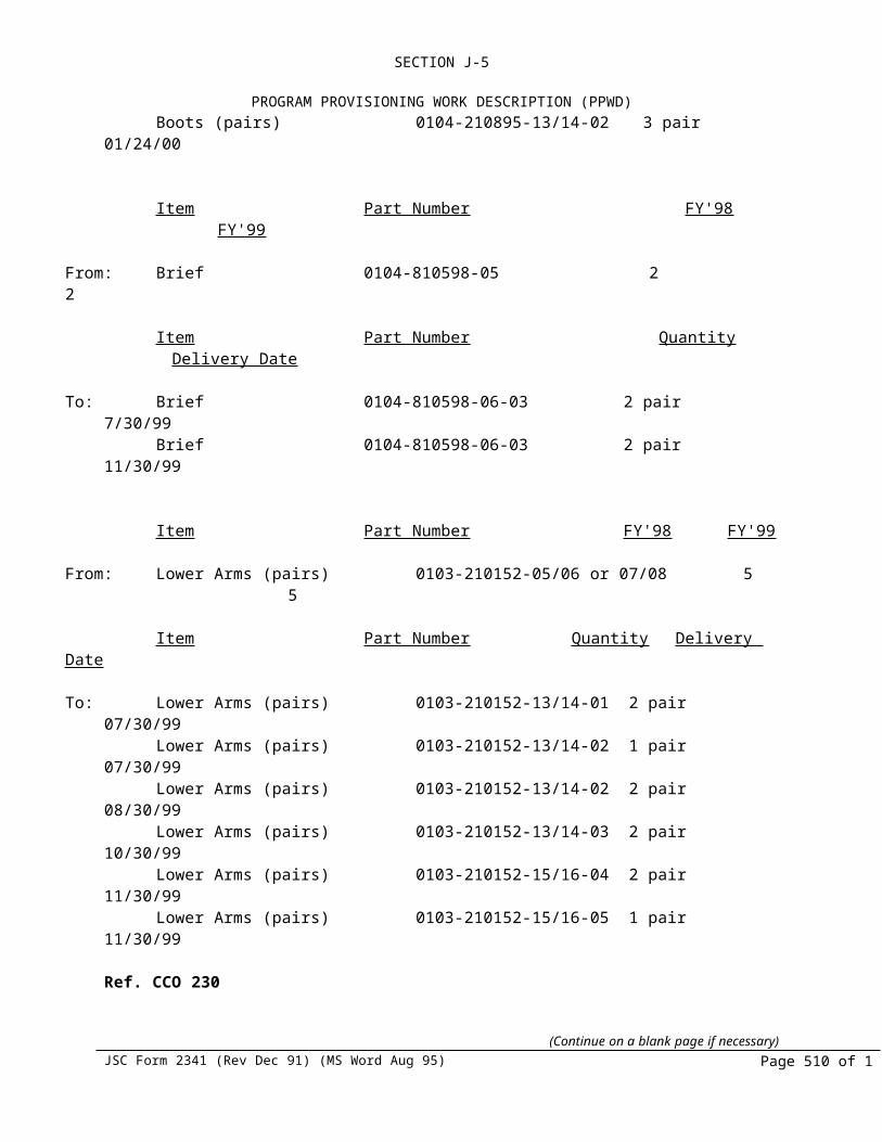
SECTION J OF 9-BL3-08-7-03PLIST OF ATTACHMENTS
OPPORTUNITIES OFFERED TO SMALL, SMALL DISADVANTAGED, AND WOMEN OWNED BUSINESS - FAR 52.219-9. (d). (8)
The HSSSI Small Business Liaison Representative and Procurement supervisors are chartered with the responsibility of:
1. Ensuring that all procurement personnel are aware of and impressed with the need to develop sources for materials and services that include Small, Small Disadvantaged, and Women Owned Businesses to the greatest possible extent.
2. Ensuring that the separate percentage goals for the utilization of Small, Small Disadvantaged and Women Owned Business as subcontractors in the execution of a particular program are met.
3. Assisting Small, Small Disadvantaged, and Women Owned businesses by arranging solicitation and providing guidance to facilitate their participation in the competitive process.
4. Ensuring that any offerer (Large Business) responding to a Request For Quotation shall include the clause entitled, “Utilization of Small Business Concerns and Small Disadvantaged Business Concerns” in all lower tier subcontracts that offer subcontracting possibilities and assuring that any offerer is in compliance with Public Laws 95-507, 99-661, 100-180 (Section 806), and Federal Acquisition Regulation 52.219 and 19.7.
5. Provide notice to Subcontractors similar to that in the solicitation provision in 52.219-1, concerning penalties for misrepresentation of business status as Small Business or Small Disadvantaged Business or Women Owned Small Business Concern for the purpose of obtaining a subcontract supporting the subcontracting goals established in the contractor’s subcontracting plan.
6. Report to the Purchasing Manager, on a regular basis, their progress on any corrective action if required, to facilitate their participation in a Small, Small Disadvantaged, and Women Owned business support program.
HS’s established Small, Small Disadvantaged, and Women Owned Business Program ensures that a concerted effort will be made to utilize Small, Small Disadvantaged, and Women Owned Business Enterprises in the performance of this contract. HSSSI has designated a Small Business Liaison Representative who is the primary contact for the purpose of gathering and disseminating information concerning potential suppliers.
The HS Small Business Liaison Officer is responsible for training, auditing, and motivating all Purchasing personnel in addition to the responsibility regarding Purchasing Policy and Procedures. A thorough familiarization of PL 95-507, PL 99-661 and other Buyer training seminars related to Small, Small Disadvantaged, and Women Owned Businesses are included as part of the training program. This training provides guidance to HSSSI personnel in assisting Small, Small Disadvantaged and Women Owned Business concerns in competing for subcontract opportunities at HSSSI.
47
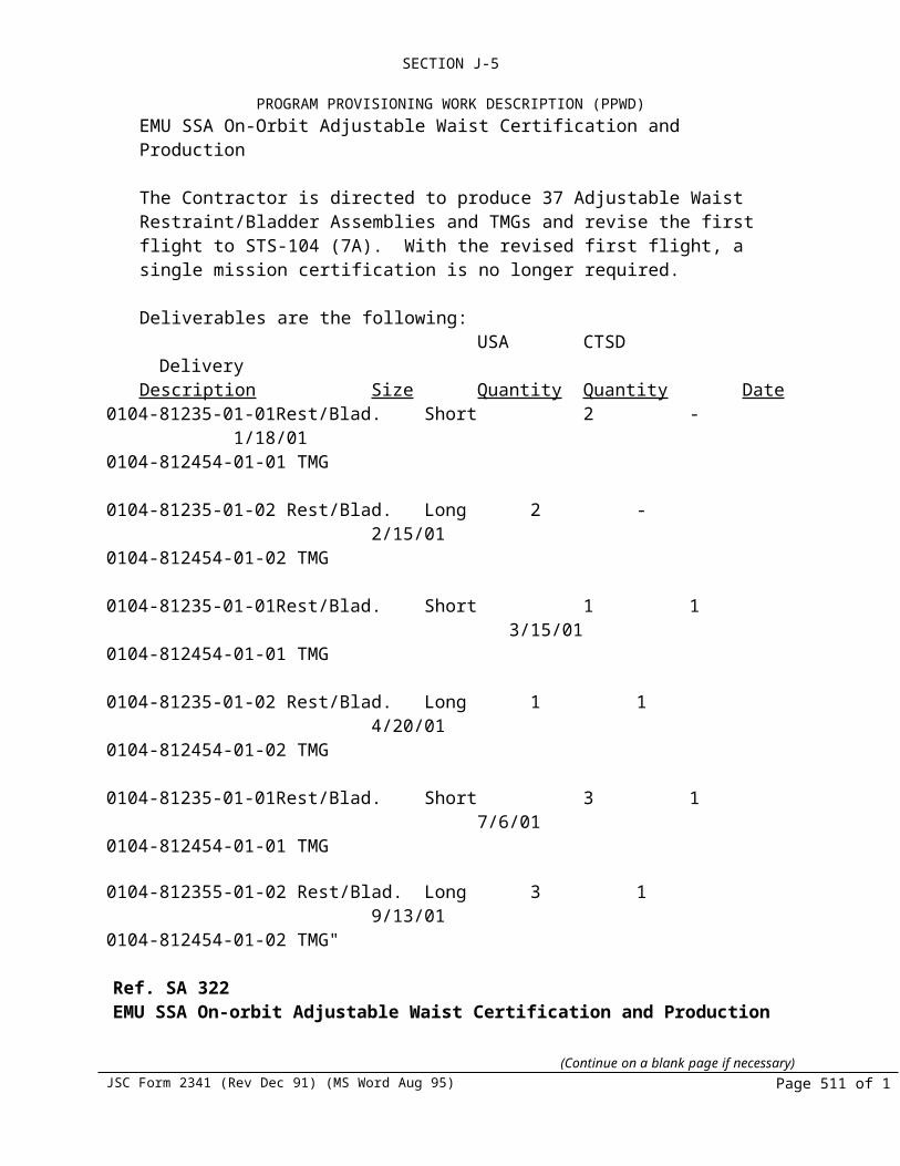
SECTION J OF 9-BL3-08-7-03PLIST OF ATTACHMENTS
HSSSI provides technical assistance to Small, Small Disadvantaged, and Women Owned businesses when deficiencies are encountered during quality system reviews. Also, assistance is provided when suppliers are required to generate special procedures.
FAR CLAUSE, “UTILIZATION OF SMALL, SMALL DISADVANTAGED, AND WOMEN OWNED BUSINESS CONCERNS” - FAR 52.219-9. (d). (9)
Assurance is hereby provided that HSSSI will include the clause entitled, “Utilization of Small, Small Disadvantaged and Women Owned Business Concerns” (FAR 52.219-8) in all subcontracts which offer further subcontracting possibilities in the United States, and will require all subcontractors (except Small Business concerns) who receive subcontracts in excess of $500,000 or in the case of contracts for the construction of any public facility, $1,000,000 to adopt and comply with a subcontracting plan (FAR 52.219-9) similar to the plan agreed to by HSSSI.
The SBLR will review the subcontractor’s subcontracting plan for compliance with the provisions of Public Law 95-507 assuring that all minimum requirements of an acceptable subcontracting plan have been satisfied and/or as time and availability of funds permit, making periodic visits to the subcontractor’s facilities to review applicable records and subcontracting program progress. The failure of the subcontractor to comply, in good faith, with an approved plan in accordance with 52.219-9 shall be considered a breach of the contract.
STUDIES, SURVEYS, REPORTS - FAR 52.219-9. (d). (10). (i). (ii). (iii). (iv)
HSSSI will cooperate in any studies or surveys as may be required, submit periodic reports in order to allow HSSSI to determine the extent of compliance by the offerer with the subcontracting plan, ensure that the subcontractors agree to submit Standard Form (SF) 294, Subcontracting Report for Individual Contracts, semi-annually for the six months ending March 31 and September 30, and/or Standard Form (SF) 295 Summary Subcontract Report. The (SF)295 is prescribed for use in the collection of data from subcontractors which hold one or more contracts over $500,000 ($1 million for construction) and are required to subcontract with Small, Small Disadvantaged, and Women Owned Business Concerns under a subcontract plan per the Small Business Act of 1958 as amended by Public Law 95-507.
48

SECTION J OF 9-BL3-08-7-03PLIST OF ATTACHMENTS
TYPES OF RECORDS MAINTAINED, FAR 52.219-9. (d). (11). (i). (ii). (iii). (iv). (v)
HS and HSSSI will maintain the following records to demonstrate procedures that have been adopted to comply with the requirements and goals in this subcontracting plan.
(i). Source Lists. Guides and other data that identify Small, Small Disadvantaged and Women Owned Business concerns.
(ii). Organizations contacted in an attempt to locate sources that are Small, Small Disadvantaged, and Women Owned businesses.
(iii). Records on each subcontract solicitation resulting in an award of more than $100,000 indicating (a) whether Small business concerns were solicited and, (b) whether Small Disadvantaged business concerns were solicited and, (c) whether Women Owned small business concerns were solicited, and (d) if applicable, the reason award was not made to a small business concern.
(iv). Records of any outreach efforts to contact (a) trade associates, (b) business development organizations, and (c) conferences and trade fairs to locate Small, Small Disadvantaged, and Women Owned Small Business sources.
(v). Records of internal guidance and encouragement provided to buyers through (a) workshops, seminars, training, etc., and (b) monitoring performance to evaluate compliance with the program’s requirements.
MANAGEMENT INVOLVEMENT AND OUTREACH
Hamilton Standard has been, and continues to be, an active participant in seminars, workshops, and purchasing councils that foster and encourage the development of Small, Small Disadvantaged, and Women Owned Businesses. Participation and representation includes both managers and buying personnel from the division procurement departments.
The Small Business Liaison Officer, Small Business Liaison Representative, and other Hamilton Standard personnel participated in events such as the following, where they counseled, interviewed, furnished supplier questionnaires and assisted with programs which will provide a benefit to the owners and management of Small, Small Disadvantaged, and Women Owned Business concerns.
1993 OUTREACH EVENTS AND PROGRAMS
NASA / Arizona Regional Aerospace Procurement Conference (2/93) NASA / Illinois Procurement Conference (5/93) NASA / New England Procurement Conference (8/93) NASA / Missouri Procurement Conference (11/93)
49

SECTION J OF 9-BL3-08-7-03PLIST OF ATTACHMENTS
1994 OUTREACH EVENTS AND PROGRAMS
Business opportunities with NASA for Connecticut Small, Small Disadvantaged, and Women Owned Business Companies (3/94)
NASA / Arizona Regional Aerospace Procurement Conference (4/94) State of Vermont Business Exposition (5/94) NASA / New England Procurement Conference (8/94)
1995 OUTREACH EVENTS AND PROGRAMS
Sikorsky Aircraft SDB Trade Fair (3/95) Small Business Conference sponsored by Defense Logistics Agency and
Congressman Neal (Ma.) (11/95)Small Business Trade Fair sponsored by Congresswoman DeLaurno (Ct.) (12/95)
1996 OUTREACH EVENTS AND PROGRAMS
Sikorsky Aircraft SDB Trade Fair (3/96) Congressman Frank’s Trade Fair (Ct.) (4/96) SBA Small Business Week, Washington, D.C. (5/97) NASA Technology & Business Conference, Springfield, Ma. (8/96) CMPC Trade Fair, Southington, Ct. (9/96) MED Week, Washington, D.C.(9/96) Congressman Neal Trade Fair (Ma.) (11/96)
1997 OUTREACH EVENTS AND PROGRAMS TRIAD Meeting/Trade Fair, Orlando Fl. (1/97) Small Business Week, Washington, D.C. (4/97) CMSDC Trade Fair, Southington, Ct. (6/97) NASA Technology & Business Conference, Stamford, Ct. (8/97) HS sponsored CEO breakfast on behalf of CMSDC (11/97) HS sponsored Mentor-Protegee Forum for SB/SDB/WO Business (11/97)
RECOGNITION / AWARDS RECEIVED
A. SBA’s Region One “Corporate Award” 1991B. DLA’s “Award of Excellence” 1992C. Connecticut Minority Purchasing Council’s 1993 “Corporation of the Year” AwardD. DLA “Special Achievement” recognition for 1994 exceeding the 5% goal for Prime ContractorsE. SBA’s “Award of Distinction” 1994F. “Dwight D. Eisenhower Award of Excellence” 1995G DLA’s “Award of Excellence” 1995H. Rockwell International Space System Division’s 1995 “Exceptional Company Performance Award”I. NASA’s “Commitment to Excellence Award” 1995 for Small and Small Disadvantaged Business UtilizationJ. NASA’s “George M. Low” Award 1995
50

SECTION J OF 9-BL3-08-7-03PLIST OF ATTACHMENTS
MASTER SUBCONTRACTING PLANFOR SMALL, SMALL DISADVANTAGED, AND WOMEN OWNED BUSINESSES
In accordance with FAR 19.704(b), this Master Subcontracting Plan is in force for the life of all applicable individual proposals and contracts.
Approved by:
____________________________________________Customer NameTitleCustomer Address
Hamilton Standard Space Systems International, Inc.United Technologies CorporationOne Hamilton RoadWindsor Locks, CT 06096
51