om, mcculloch, cabrio 433 l, 952715745, 2010-12, brush · pdf fileinstruction manual important...
TRANSCRIPT

115306026 Rev. 3 11/15/10 BRW
INSTRUCTION MANUALIMPORTANT INFORMATION: Please read these instructions carefully and makesure you understand them before using this unit. Retain these instructions for futurereference.
MANUEL D’INSTRUCTIONSRENSEIGNEMENTS IMPORTANTS: Avant d’utiliser cet appareil, veuillez lireatentivement les instructions et assurez--vous de les avoir comprises. Conservezles instructions pour référence ultérieure.
BETRIEBSANWEISUNGWICHTIGE INFORMATION: Lesen Sie diese Hinweise zur Handhabung desGeräts aufmerksam durch. Verwenden Sie es erst, wenn Sie sicher sind, daß Siealle Anweisungen verstanden haben und gut aufbewahren.
MANUAL DE INSTRUCCIONESINFORMACIÓN IMPORTANTE: Lea atentamente las instrucciones yasegúrese de entenderlas antes de utilizar esta aparato. Conserve las instruc-ciones para la referencia en el futuro.
GB
FR
DE
ES
2
TABLE OF CONTENTS
Identification (What is What?) 2Identification of Symbols 3Safety Rules 3Assembly 5Operation 9Maintenance 15
Service & Adjustments 16Storage 18Troubleshooting Table 19Declaration of Conformity 20Technical Data 21
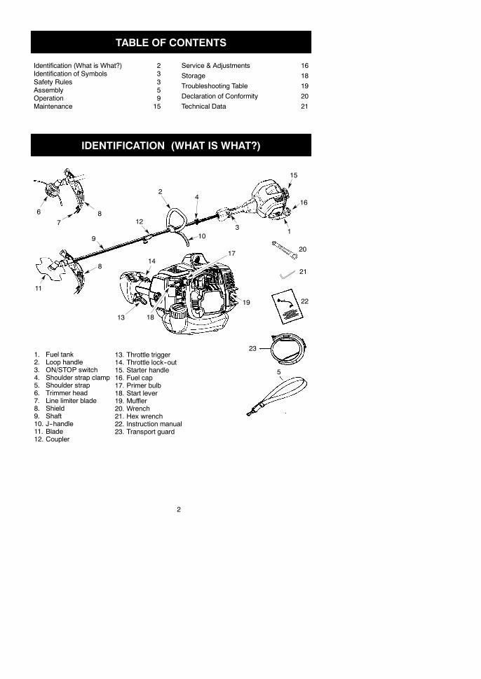
IDENTIFICATION (WHAT IS WHAT?)
310
1
416
14
20
19
7
2
17
8
6
9
18
21
5
13
15
11
12
22
8
231. Fuel tank2. Loop handle3. ON/STOP switch4. Shoulder strap clamp5. Shoulder strap6. Trimmer head7. Line limiter blade8. Shield9. Shaft10. J--handle11. Blade12. Coupler
13. Throttle trigger14. Throttle lock--out15. Starter handle16. Fuel cap17. Primer bulb18. Start lever19. Muffler20. Wrench21. Hex wrench22. Instruction manual23. Transport guard

3
IDENTIFICATION OF SYMBOLSA.
B.
C.
D.
E.
F.
G.
H.
I.
J.
K.
D. DANGER! Blade can thrust violently away frommaterial it does not cut. Blade thrustcan cause amputation of arms or legs. Keep people and animals 15 meters away.
E. WARNING! Blade/trimmer line can throw objects violently. You and others can beblinded or injured. Always wear eye protection and leg protection.
F. The operator of the machine must insure that no one comes within a 15 meter radiuswhile working. When several operators are working within the same area a safety dis-tance of at least 15 meters must be observed.
G. Use unleaded or quality leaded petrol and two--stroke oil mixed at a ratio of 2.5%.H. Assist handle to be positioned only below the arrow.I. Engine ON/STOP switch.J. Guaranteed sound power level according to Directive 2000/14/ECK. Maximum rotational frequency of the spindle, rpm
A. WARNING! This brushcutter can be dangerous! Careless or improper use cancause serious or even fatal injury.
B. Read and understand the instruction manual before using the brushcutter.C. Always use:
Ear protection, eye protection, head protection, boots, and gloves.
SAFETY RULES
WARNING: When using gardeningappliances, basic safety precautions should al-ways be followed to reduce the risk of fire andserious injury. Read and follow all instructions.
DANGER: This power tool can be dan-gerous! This unit can cause serious injury in-cluding amputation or blindness to the operatorand others. The warnings and safety instruc-tions in this manual must be followed to providereasonable safety and efficiency in using theunit. Theoperator is responsible for following thewarnings and instructions in this manual and onthe unit. Read the entire instruction manual be-fore assembling and using the unit! Restrict theuse of this unit to persons who read, under-stand, and follow the warnings and instructionsin this manual and on the unit. Never allow chil-dren to operate this unit.
SAFETY INFORMATIONON THE UNIT
INSTRUCTIONMANUAL
DANGER: Blade can thrust violentlyaway from material it does not cut. Bladethrust can cause amputation of arms or legs.Keep people and animals 15 meters away.
WARNING: Blade/trimmer line canthrow objects violently. You andothers canbeblinded or injured. Wear safety glasses andleg protection.
4
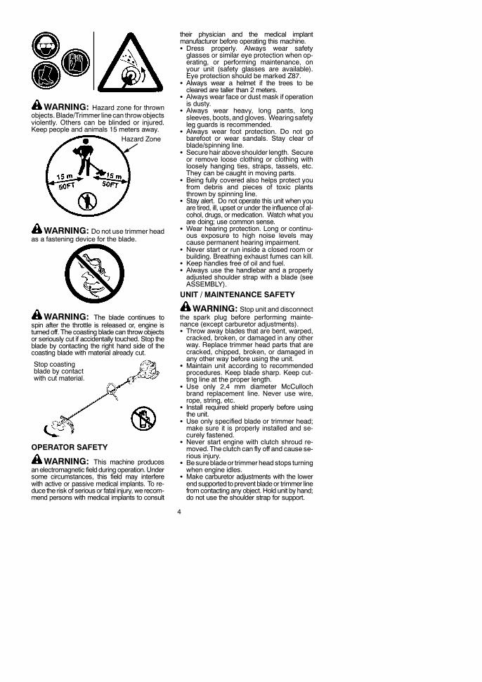
WARNING: Hazard zone for thrownobjects.Blade/Trimmer linecan throwobjectsviolently. Others can be blinded or injured.Keep people and animals 15 meters away.
Hazard Zone
WARNING: Do not use trimmer headas a fastening device for the blade.
WARNING: The blade continues tospin after the throttle is released or, engine isturned off. The coasting blade can throwobjectsor seriously cut if accidentally touched. Stop theblade by contacting the right hand side of thecoasting blade with material already cut.
Stop coastingblade by contactwith cut material.
OPERATOR SAFETY
WARNING: This machine producesanelectromagnetic fieldduring operation.Undersome circumstances, this field may interferewith active or passive medical implants. To re-duce the risk of serious or fatal injury, we recom-mend persons with medical implants to consult
their physician and the medical implantmanufacturer before operating this machine.S Dress properly. Always wear safetyglasses or similar eye protection when op-erating, or performing maintenance, onyour unit (safety glasses are available).Eye protection should be marked Z87.
S Always wear a helmet if the trees to becleared are taller than 2 meters.
S Always wear face or dust mask if operationis dusty.
S Always wear heavy, long pants, longsleeves, boots, and gloves. Wearingsafetyleg guards is recommended.
S Always wear foot protection. Do not gobarefoot or wear sandals. Stay clear ofblade/spinning line.
S Secure hair above shoulder length. Secureor remove loose clothing or clothing withloosely hanging ties, straps, tassels, etc.They can be caught in moving parts.
S Being fully covered also helps protect youfrom debris and pieces of toxic plantsthrown by spinning line.
S Stay alert. Do not operate this unit when youare tired, ill, upset or under the influence of al-cohol, drugs, or medication. Watch what youare doing; use common sense.
S Wear hearing protection. Long or continu-ous exposure to high noise levels maycause permanent hearing impairment.
S Never start or run inside a closed room orbuilding. Breathing exhaust fumes can kill.
S Keep handles free of oil and fuel.S Always use the handlebar and a properlyadjusted shoulder strap with a blade (seeASSEMBLY).
UNIT / MAINTENANCE SAFETY
WARNING: Stop unit and disconnectthe spark plug before performing mainte-nance (except carburetor adjustments).S Throw away blades that are bent, warped,cracked, broken, or damaged in any otherway. Replace trimmer head parts that arecracked, chipped, broken, or damaged inany other way before using the unit.
S Maintain unit according to recommendedprocedures. Keep blade sharp. Keep cut-ting line at the proper length.
S Use only 2,4 mm diameter McCullochbrand replacement line. Never use wire,rope, string, etc.
S Install required shield properly before usingthe unit.
S Use only specified blade or trimmer head;make sure it is properly installed and se-curely fastened.
S Never start engine with clutch shroud re-moved. The clutch can fly off and cause se-rious injury.
S Besurebladeor trimmer head stops turningwhen engine idles.
S Make carburetor adjustments with the lowerendsupported toprevent bladeor trimmer linefromcontacting any object. Hold unit by hand;do not use the shoulder strap for support.

5
S Keep others away whenmaking carbure-tor adjustments.
S Useonly recommendedMcCulloch accesso-ries and replacement parts.
S Have all maintenance and service not ex-plained in this manual performed by your au-thorized service dealer.
FUEL SAFETYS Mix and pour fuel outdoors.S Keep away from sparks or flames.S Use a container approved for fuel.S Do not smoke or allow smoking near fuel orthe unit.
S Avoid spilling fuel or oil. Wipe up all fuel spills.S Move at least 3 meters away from fuelingsite before starting engine.
S Stop engine and allow to cool before re-moving fuel cap.
S Always store petrol in a container approvedfor flammable liquids.
CUTTING SAFETY
WARNING: Inspect the area to be cutbefore each use. Remove objects (rocks,broken glass, nails, wire, string, etc.) whichcan be thrown or become entangled in theblade or trimmer head.S Keep others including children, animals,bystanders, and helpers at least 15metersaway. Stop engine immediately if you areapproached.
S Always keep engine on the right--hand sideof your body.
S Hold the unit firmly with both hands.S Keep firm footing and balance. Do notoverreach.
S Keep blade or trimmer head below waistlevel. Do not raise engine above your waist.
S Keep all parts of your body away from blade,trimmer head, and muffler when engine is
running. A hot muffler can cause seriousburns.
S Cut from your left to your right. Cutting onright side of the shield will throw debrisaway from the operator.
S Use only in daylight or good artificial light.S Use only for jobs explained in this manual.TRANSPORTING AND STORAGES Allow the engine to cool; secure unit beforestoring or transporting in vehicle.
S Empty fuel tank before storing or transportingthe unit. Use up fuel left in the carburetor bystarting engine and letting it run until it stops.
S Store unit and fuel in an areawhere fuel va-pors cannot reach sparks or open flamesfrom water heaters, electric motors orswitches, furnaces, etc.
S Store unit so line limiter cannot accidentallycause injury. Unit can be hung by the shaft.
S Always install transport guard on blade be-fore transporting or strorage.
S Store the unit out of the reach of children.S Secure the machine during transport.SPECIAL NOTICE: Exposure to vibra-tions through prolonged use of petrol pow-ered hand tools could cause blood vessel ornerve damage in the fingers, hands, andjoints of people prone to circulation disordersor abnormal swellings. Prolonged use in coldweather has been linked toblood vesseldam-age in otherwise healthy people. If symptomsoccur such as numbness, pain, loss ofstrength, change in skin color or texture, orloss of feeling in the fingers, hands, or joints,discontinue the use of this tool and seekmed-ical attention. An anti-vibration system doesnot guarantee the avoidance of these prob-lems. Users who operate power tools on acontinual and regular basis must monitorclosely their physical condition and the condi-tion of this tool.
ASSEMBLYCARTON CONTENTSCheck carton contents against the following list:S PowerheadS Trimmer attachmentS Trimmer head
S BladeS Cupped washerS Large nut for installing bladeS Combination shieldS BoltS Loop handleS Securing plateS BoltS Wing nut
S J--handleS Upper shoulder strap clampS Lower shoulder strap clampS Shoulder strap screws (2)S Shoulder strapS Hex wrenchS WrenchS Transport guard
WARNING: Always stop unit and dis-connect spark plug before performing any as-sembly procedures.
WARNING: If received assembled,repeat all steps to ensure your unit is properlyassembled and all fasteners are secure.Examine parts for damage. Do not use dam-aged parts.It is normal for the fuel filter to rattle in theempty fuel tank.Finding fuel or oil residue onmuffler is normaldue to carburetor adjustments and testingdone by the manufacturer.TOOLS REQUIREDS Hex wrench (provided)S Adjustable wrenchS Phillips screwdriver

6
INSTALLING TRIMMERATTACHMENT
WARNING: When installing attach-ment, place the unit on a flat surface for stabil-ity.1. Loosen the coupler by turning the knob
counterclockwise.
Shippingprotector
Coupler
Knob
LOOSEN
TIGHTEN2. Remove shipping protector from coupler.3. Remove the shaft cap from the attachment
(if present).4. Position locking/release button of attach-
ment into guide recess of coupler.5. Push the attachment into the coupler until
the locking/release button snaps into theprimary hole.
6. Before using the unit, tighten the knob se-curely by turning clockwise.
Coupler Primary Hole
UpperShaft
Locking/ReleaseButton
Attachment
Guide Recess
WARNING: Make sure the locking/release button is locked in the primary holeand the knob is securely tightened before op-erating the unit. All attachments are designedto be used in the primary hole unless otherwisestated in the applicable attachment instructionmanual. Using thewronghole could lead toseri-ous injury or damage to the unit.
Locking/ReleaseButton in Primary Hole
For optional attachments, see the ASSEMBLYsection of the applicable attachment instructionmanual.
ATTACHING THE HANDLE
DANGER: To avoid serious injury, thebarrier portion of the handlemust be installed asshown to provide a barrier between operatorand the spinning blade.1. Position the loop handle on the shaft. Note
that the handle must be mounted betweenthe arrows on the shaft.
Wrench
Handle Bolt
Securingplate
Nut
2. Install the bolt, securing plate and nut asshown in the illustration.
3. Make a final adjustment of the handle to acomfortableworking position. Tighten thenut firmly with wrench (provided).
ASSEMBLY OF SHOULDER STRAP1. Place the upper shoulder strap clamp
over the shaft.2. Position the lower shoulder strap clamp
under the shaft and align the upper andlower clamp screw holes.
Upper shoulderstrap clamp
ScrewsLower shoulderstrap clamp
3. Insert two screws into the screw holes.4. Secure shoulder strap clamp by tighten-
ing screws with a hex wrench.
WARNING: Proper shoulder strap andhandlebar adjustments must be made with theengine completely stopped before using unit.
7
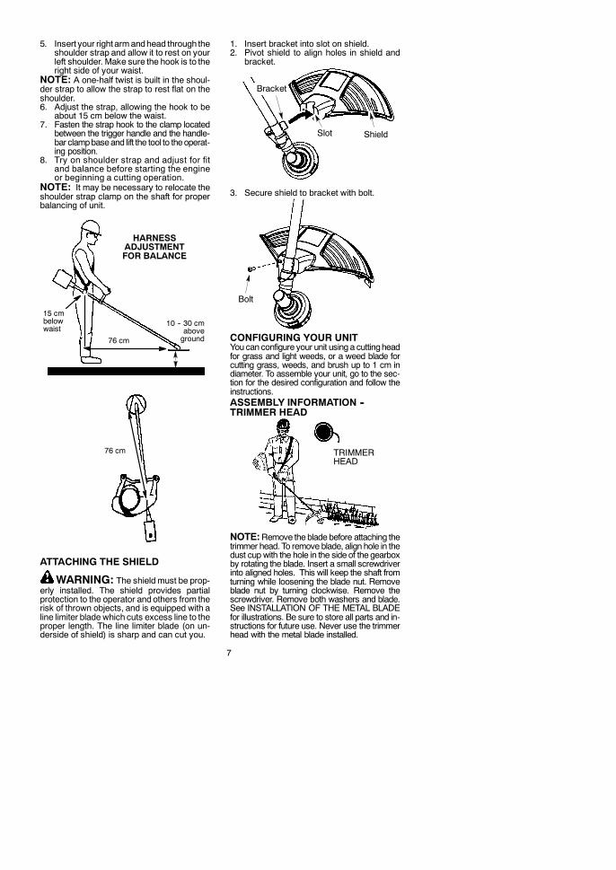
5. Insert your right armandhead through theshoulder strap and allow it to rest on yourleft shoulder. Make sure the hook is to theright side of your waist.
NOTE: A one-half twist is built in the shoul-der strap to allow the strap to rest flat on theshoulder.6. Adjust the strap, allowing the hook to be
about 15 cm below the waist.7. Fasten the strap hook to the clamp located
between the trigger handle and the handle-bar clampbaseand lift the tool to theoperat-ing position.
8. Try on shoulder strap and adjust for fitand balance before starting the engineor beginning a cutting operation.
NOTE: It may be necessary to relocate theshoulder strap clamp on the shaft for properbalancing of unit.
76 cm
HARNESSADJUSTMENTFOR BALANCE
10 -- 30 cmaboveground
15 cmbelowwaist
76 cm
ATTACHING THE SHIELD
WARNING: The shield must be prop-erly installed. The shield provides partialprotection to the operator and others from therisk of thrown objects, and is equipped with aline limiter blade which cuts excess line to theproper length. The line limiter blade (on un-derside of shield) is sharp and can cut you.
1. Insert bracket into slot on shield.2. Pivot shield to align holes in shield and
bracket.
Slot Shield
Bracket
3. Secure shield to bracket with bolt.
Bolt
CONFIGURING YOUR UNITYou can configure your unit using a cuttingheadfor grass and light weeds, or a weed blade forcutting grass, weeds, and brush up to 1 cm indiameter. To assemble your unit, go to the sec-tion for the desired configuration and follow theinstructions.ASSEMBLY INFORMATION --TRIMMER HEAD
TRIMMERHEAD
NOTE:Remove the blade before attaching thetrimmer head. To remove blade, align hole in thedust cup with the hole in the side of the gearboxby rotating the blade. Insert a small screwdriverinto aligned holes. This will keep the shaft fromturning while loosening the blade nut. Removeblade nut by turning clockwise. Remove thescrewdriver. Remove both washers and blade.See INSTALLATION OF THE METAL BLADEfor illustrations. Be sure to store all parts and in-structions for future use. Never use the trimmerhead with the metal blade installed.
8
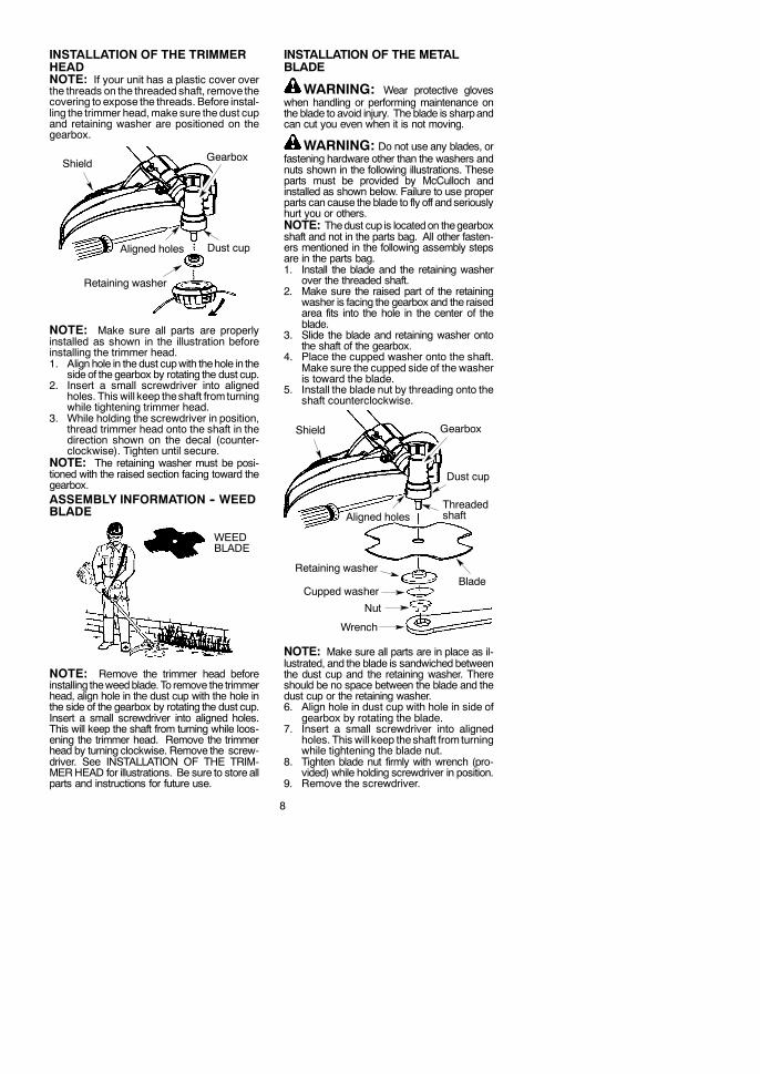
INSTALLATION OF THE TRIMMERHEADNOTE: If your unit has a plastic cover overthe threads on the threaded shaft, remove thecovering to expose the threads. Before instal-ling the trimmer head,make sure the dust cupand retaining washer are positioned on thegearbox.
Retaining washer
Dust cup
Gearbox
Aligned holes
Shield
NOTE: Make sure all parts are properlyinstalled as shown in the illustration beforeinstalling the trimmer head.1. Align hole in the dust cupwith thehole in the
side of the gearbox by rotating the dust cup.2. Insert a small screwdriver into aligned
holes. This will keep theshaft fromturningwhile tightening trimmer head.
3. While holding the screwdriver in position,thread trimmer head onto the shaft in thedirection shown on the decal (counter-clockwise). Tighten until secure.
NOTE: The retaining washer must be posi-tioned with the raised section facing toward thegearbox.ASSEMBLY INFORMATION -- WEEDBLADE
WEEDBLADE
NOTE: Remove the trimmer head beforeinstalling theweedblade.To remove the trimmerhead, align hole in the dust cup with the hole inthe side of the gearbox by rotating the dust cup.Insert a small screwdriver into aligned holes.This will keep the shaft from turning while loos-ening the trimmer head. Remove the trimmerhead by turning clockwise. Remove the screw-driver. See INSTALLATION OF THE TRIM-MERHEAD for illustrations. Be sure to store allparts and instructions for future use.
INSTALLATION OF THE METALBLADE
WARNING: Wear protective gloveswhen handling or performing maintenance onthe blade to avoid injury. The blade is sharpandcan cut you even when it is not moving.
WARNING: Do not use any blades, orfastening hardware other than the washers andnuts shown in the following illustrations. Theseparts must be provided by McCulloch andinstalled as shown below. Failure to use properparts can cause the blade to fly off andseriouslyhurt you or others.NOTE: Thedust cup is locatedon thegearboxshaft and not in the parts bag. All other fasten-ers mentioned in the following assembly stepsare in the parts bag.1. Install the blade and the retaining washer
over the threaded shaft.2. Make sure the raised part of the retaining
washer is facing the gearbox and the raisedarea fits into the hole in the center of theblade.
3. Slide the blade and retaining washer ontothe shaft of the gearbox.
4. Place the cupped washer onto the shaft.Make sure the cupped side of the washeris toward the blade.
5. Install the blade nut by threading onto theshaft counterclockwise.
Shield
BladeRetaining washer
Aligned holes
Cupped washer
Nut
Threadedshaft
Wrench
Dust cup
Gearbox
NOTE: Make sure all parts are in place as il-lustrated, and the blade is sandwiched betweenthe dust cup and the retaining washer. Thereshould be no space between the blade and thedust cup or the retaining washer.6. Align hole in dust cup with hole in side of
gearbox by rotating the blade.7. Insert a small screwdriver into aligned
holes. This will keep theshaft fromturningwhile tightening the blade nut.
8. Tighten blade nut firmly with wrench (pro-vided) while holding screwdriver in position.
9. Remove the screwdriver.
9
10. Turn blade by hand. If the blade bindsagainst the shield, or appears to be uneven,the blade is not centered, and you must re-install.
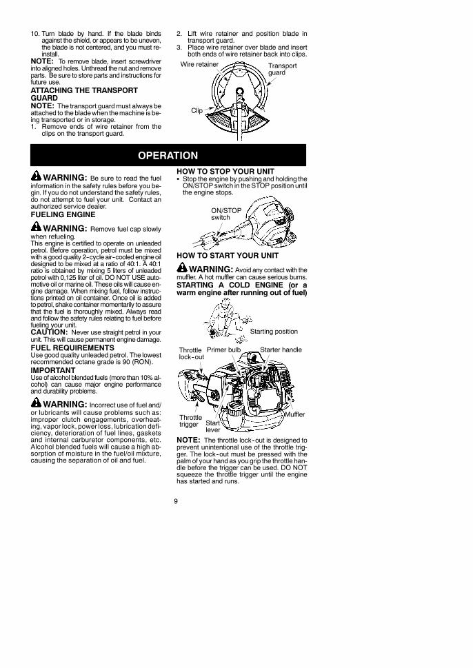
NOTE: To remove blade, insert screwdriverinto aligned holes. Unthread thenut and removeparts. Be sure to store parts and instructions forfuture use.ATTACHING THE TRANSPORTGUARDNOTE: The transport guardmust always beattached to the bladewhen themachine is be-ing transported or in storage.1. Remove ends of wire retainer from the
clips on the transport guard.
2. Lift wire retainer and position blade intransport guard.
3. Place wire retainer over blade and insertboth ends of wire retainer back into clips.
Wire retainer Transportguard
Clip
OPERATION
WARNING: Be sure to read the fuelinformation in the safety rules before you be-gin. If you do not understand the safety rules,do not attempt to fuel your unit. Contact anauthorized service dealer.FUELING ENGINE
WARNING: Remove fuel cap slowlywhen refueling.This engine is certified to operate on unleadedpetrol. Before operation, petrol must be mixedwith a goodquality 2--cycleair--cooled engineoildesigned to be mixed at a ratio of 40:1. A 40:1ratio is obtained by mixing 5 liters of unleadedpetrol with 0,125 liter of oil. DO NOT USE auto-motive oil ormarine oil. These oilswill causeen-gine damage. When mixing fuel, follow instruc-tions printed on oil container. Once oil is addedtopetrol, shakecontainermomentarily toassurethat the fuel is thoroughly mixed. Always readand follow the safety rules relating to fuel beforefueling your unit.CAUTION: Never use straight petrol in yourunit. This will cause permanent engine damage.FUEL REQUIREMENTSUse good quality unleaded petrol. The lowestrecommended octane grade is 90 (RON).IMPORTANTUseof alcohol blended fuels (more than 10%al-cohol) can cause major engine performanceand durability problems.
WARNING: Incorrect use of fuel and/or lubricants will cause problems such as:improper clutch engagements, overheat-ing, vapor lock, power loss, lubrication defi-ciency, deterioration of fuel lines, gasketsand internal carburetor components, etc.Alcohol blended fuels will cause a high ab-sorption of moisture in the fuel/oil mixture,causing the separation of oil and fuel.
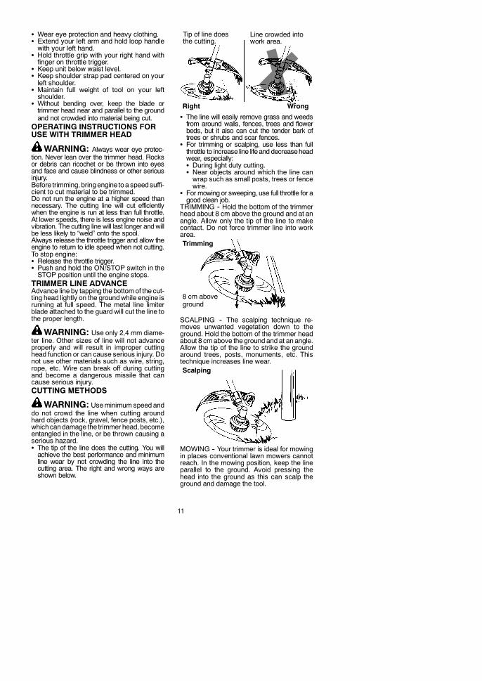
HOW TO STOP YOUR UNITS Stop the engine by pushing and holding theON/STOP switch in theSTOP position untilthe engine stops.
ON/STOPswitch
HOW TO START YOUR UNIT
WARNING: Avoid any contact with themuffler. A hot muffler can cause serious burns.STARTING A COLD ENGINE (or awarm engine after running out of fuel)
Starting position
MufflerStartlever
Starter handlePrimer bulb
Throttletrigger
Throttlelock--out
NOTE: The throttle lock--out is designed toprevent unintentional use of the throttle trig-ger. The lock--out must be pressed with thepalmof your hand as you grip the throttle han-dle before the trigger can be used. DO NOTsqueeze the throttle trigger until the enginehas started and runs.

10
1. Set unit on a flat surface.2. Slowly press the primer bulb 6 times.3. Move the start lever to the START position.4. Pull starter rope handle sharply until en-
gine starts and runs.5. Allow unit to run for 10--15 seconds, then
fully squeeze the throttle trigger to disen-gage the starting system.
STARTING A WARM ENGINEPull starter rope sharply until engine startsand runs.NOTE:Normally, the warm starting procedurecan be used within 5 -- 10 minutes after the unitis turned off. If the unit sits for more than 10min-utes without being run, it will be necessary tostart the unit by following the steps underSTARTING A COLD ENGINE or following thestarting instruction steps shown on the unit.STARTING A FLOODED ENGINEMove the start lever to the RUN position andfully squeeze throttle trigger. Pull the starterhandle repeatedly while squeezing throttletrigger until engine starts and runs. This couldrequire pulling the starter handle many times,depending on how badly the unit is flooded.If the unit still doesn’t start, refer to TROUBLE-SHOOTING TABLE.OPERATING THE COUPLERThis model is equipped with a coupler whichenables optional attachments to be installed.
WARNING: Always stop unit and dis-connect spark plug before removing or instal-ling attachments.REMOVING TRIMMER ATTACH-MENT (OR OTHER OPTIONAL AT-TACHMENTS)CAUTION: When removing or installing at-tachments, place the unit on a flat surface forstability.1. Loosen the coupler by turning the knob
counterclockwise.
Attachment
Coupler
Knob
LOOSEN
TIGHTEN
2. Press and hold the locking/release button.
Locking/ReleaseButton
Coupler Upper ShaftAttachment
3. While securely holding theengine andup-per shaft, pull the attachment straight outof the coupler.
INSTALLING OPTIONAL ATTACH-MENTS1. Remove the shaft cap from the attach-
ment (if present).2. Position locking/release button of attach-
ment into guide recess of coupler.3. Push the attachment into the coupler until
the locking/release button snaps into theprimary hole.
4. Before using the unit, tighten the knob se-curely by turning clockwise.
Coupler Primary Hole
UpperShaft
Locking/ReleaseButton
Attachment
Guide Recess
WARNING: Make sure the locking/release button is locked in the primary holeand the knob is securely tightened before op-erating the unit. All attachments are designedto be used in the primary hole unless otherwisestated in the applicable attachment instructionmanual. Using thewronghole could lead toseri-ous injury or damage to the unit.
Locking/ReleaseButton in Primary Hole
OPERATING POSITIONALWAYS WEAR:
Hearingprotection
Eye protection
Heavy,long pants
Boots
Cut from your left to your right.
Safety helmet
When operating unit, clip shoulder strap ontoclamp, stand as shown and check for the fol-lowing:
11
S Wear eye protection and heavy clothing.S Extend your left arm and hold loop handlewith your left hand.
S Hold throttle grip with your right hand withfinger on throttle trigger.
S Keep unit below waist level.S Keep shoulder strap pad centered on yourleft shoulder.
S Maintain full weight of tool on your leftshoulder.
S Without bending over, keep the blade ortrimmer head near and parallel to the groundand not crowded into material being cut.
OPERATING INSTRUCTIONS FORUSE WITH TRIMMER HEAD
WARNING: Always wear eye protec-tion. Never lean over the trimmer head. Rocksor debris can ricochet or be thrown into eyesand face and cause blindness or other seriousinjury.Before trimming, bringengine toa speedsuffi-cient to cut material to be trimmed.Do not run the engine at a higher speed thannecessary. The cutting line will cut efficientlywhen the engine is run at less than full throttle.At lower speeds, there is less engine noise andvibration. The cutting line will last longer andwillbe less likely to “weld” onto the spool.Always release the throttle trigger and allow theengine to return to idle speed when not cutting.To stop engine:S Release the throttle trigger.S Push and hold the ON/STOP switch in theSTOP position until the engine stops.
TRIMMER LINE ADVANCEAdvance line by tapping the bottomof the cut-ting head lightly on the groundwhile engine isrunning at full speed. The metal line limiterblade attached to the guard will cut the line tothe proper length.
WARNING: Use only 2,4 mm diame-ter line. Other sizes of line will not advanceproperly and will result in improper cuttinghead function or can cause serious injury. Donot use other materials such as wire, string,rope, etc. Wire can break off during cuttingand become a dangerous missile that cancause serious injury.CUTTING METHODS
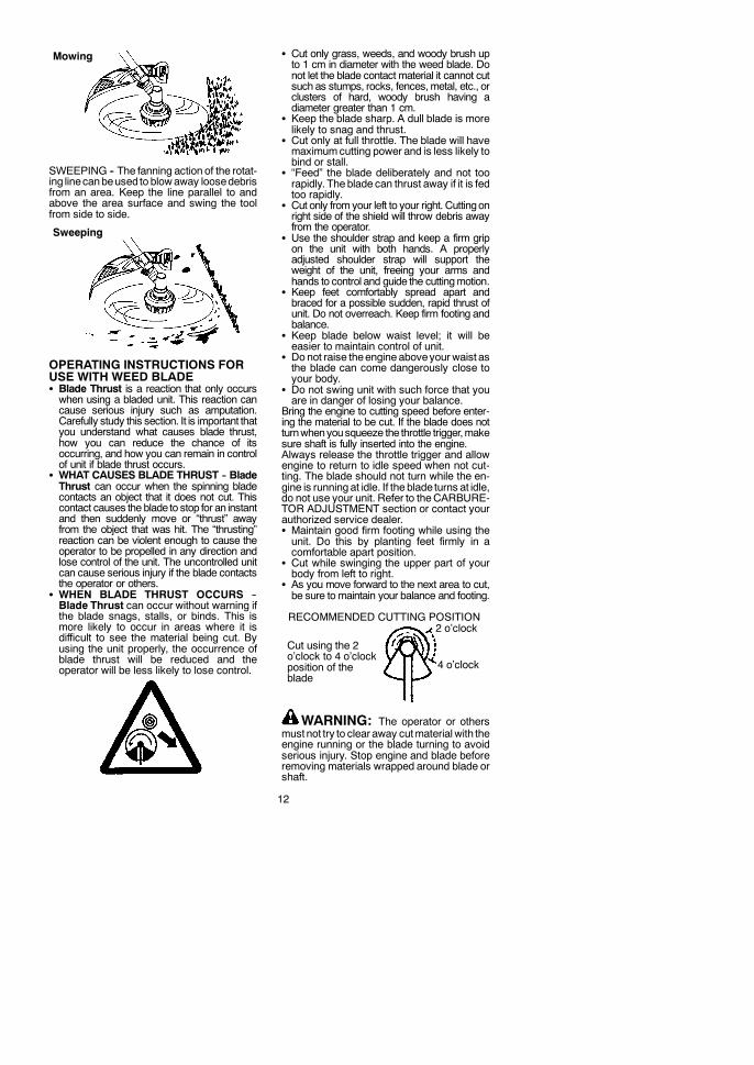
WARNING: Useminimum speed anddo not crowd the line when cutting aroundhard objects (rock, gravel, fence posts, etc.),whichcandamage the trimmer head, becomeentangled in the line, or be thrown causing aserious hazard.S The tip of the line does the cutting. You willachieve the best performance and minimumline wear by not crowding the line into thecutting area. The right and wrong ways areshown below.
Right Wrong
Tip of line doesthe cutting.
Line crowded intowork area.
S The line will easily remove grass and weedsfrom around walls, fences, trees and flowerbeds, but it also can cut the tender bark oftrees or shrubs and scar fences.
S For trimming or scalping, use less than fullthrottle to increase line lifeand decreaseheadwear, especially:S During light duty cutting.S Near objects around which the line canwrap such as small posts, trees or fencewire.
S For mowing or sweeping, use full throttle for agood clean job.
TRIMMING -- Hold the bottom of the trimmerhead about 8 cm above the ground and at anangle. Allow only the tip of the line to makecontact. Do not force trimmer line into workarea.Trimming
8 cm aboveground
SCALPING -- The scalping technique re-moves unwanted vegetation down to theground. Hold the bottom of the trimmer headabout 8 cmabove the ground and at an angle.Allow the tip of the line to strike the groundaround trees, posts, monuments, etc. Thistechnique increases line wear.Scalping
MOWING -- Your trimmer is ideal for mowingin places conventional lawn mowers cannotreach. In the mowing position, keep the lineparallel to the ground. Avoid pressing thehead into the ground as this can scalp theground and damage the tool.
12
Mowing
SWEEPING -- The fanning action of the rotat-ing linecanbeused to blowaway loosedebrisfrom an area. Keep the line parallel to andabove the area surface and swing the toolfrom side to side.
Sweeping
OPERATING INSTRUCTIONS FORUSE WITH WEED BLADES Blade Thrust is a reaction that only occurswhen using a bladed unit. This reaction cancause serious injury such as amputation.Carefully study this section. It is important thatyou understand what causes blade thrust,how you can reduce the chance of itsoccurring, and how you can remain in controlof unit if blade thrust occurs.
S WHAT CAUSES BLADE THRUST -- BladeThrust can occur when the spinning bladecontacts an object that it does not cut. Thiscontact causes the blade to stop for an instantand then suddenly move or “thrust” awayfrom the object that was hit. The “thrusting”reaction can be violent enough to cause theoperator to be propelled in any direction andlose control of the unit. The uncontrolled unitcan cause serious injury if the blade contactsthe operator or others.
S WHEN BLADE THRUST OCCURS --Blade Thrust can occur without warning ifthe blade snags, stalls, or binds. This ismore likely to occur in areas where it isdifficult to see the material being cut. Byusing the unit properly, the occurrence ofblade thrust will be reduced and theoperator will be less likely to lose control.
S Cut only grass, weeds, and woody brush upto 1 cm in diameter with the weed blade. Donot let the blade contact material it cannot cutsuch as stumps, rocks, fences,metal, etc., orclusters of hard, woody brush having adiameter greater than 1 cm.
S Keep the blade sharp. A dull blade is morelikely to snag and thrust.
S Cut only at full throttle. The blade will havemaximumcutting power and is less likely tobind or stall.
S “Feed” the blade deliberately and not toorapidly. The blade can thrust away if it is fedtoo rapidly.
S Cut only fromyour left to your right. Cuttingonright side of the shield will throw debris awayfrom the operator.
S Use the shoulder strap and keep a firm gripon the unit with both hands. A properlyadjusted shoulder strap will support theweight of the unit, freeing your arms andhands to control and guide the cuttingmotion.
S Keep feet comfortably spread apart andbraced for a possible sudden, rapid thrust ofunit. Do not overreach. Keep firm footing andbalance.
S Keep blade below waist level; it will beeasier to maintain control of unit.
S Donot raise theengine aboveyour waist asthe blade can come dangerously close toyour body.
S Do not swing unit with such force that youare in danger of losing your balance.
Bring the engine to cutting speed before enter-ing the material to be cut. If the blade does notturnwhenyousqueeze the throttle trigger,makesure shaft is fully inserted into the engine.Always release the throttle trigger and allowengine to return to idle speed when not cut-ting. The blade should not turn while the en-gine is running at idle. If the blade turns at idle,do not use your unit. Refer to theCARBURE-TOR ADJUSTMENT section or contact yourauthorized service dealer.S Maintain good firm footing while using theunit. Do this by planting feet firmly in acomfortable apart position.
S Cut while swinging the upper part of yourbody from left to right.
S As you move forward to the next area to cut,be sure to maintain your balance and footing.
Cut using the 2o’clock to 4 o’clockposition of theblade
2 o’clock
4 o’clock
RECOMMENDED CUTTING POSITION
WARNING: The operator or othersmust not try to clear away cutmaterial with theengine running or the blade turning to avoidserious injury. Stop engine and blade beforeremoving materials wrapped around blade orshaft.
13
ADDITIONAL SAFETY RULESFOR OPTIONAL ATTACHMENTS
WARNING: For each optional attach-ment used, read entire instruction manual be-fore use and follow all warnings and in-structions in manual and on attachment.
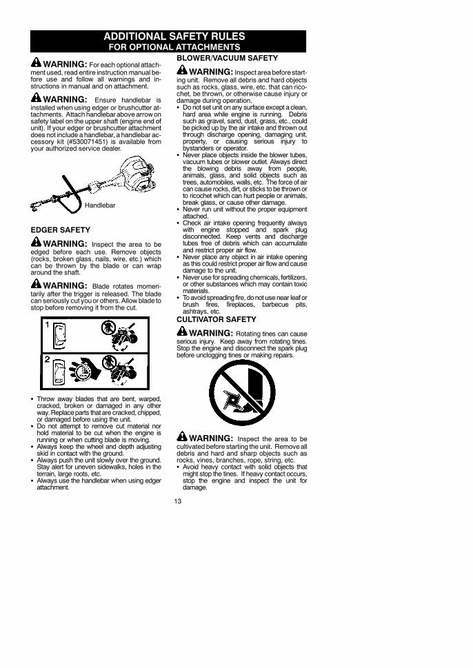
WARNING: Ensure handlebar isinstalled when using edger or brushcutter at-tachments. Attach handlebarabove arrowonsafety label on the upper shaft (engine end ofunit). If your edger or brushcutter attachmentdoes not include a handlebar, a handlebar ac-cessory kit (#530071451) is available fromyour authorized service dealer.
Handlebar
EDGER SAFETY
WARNING: Inspect the area to beedged before each use. Remove objects(rocks, broken glass, nails, wire, etc.) whichcan be thrown by the blade or can wraparound the shaft.
WARNING: Blade rotates momen-tarily after the trigger is released. The bladecan seriously cut youor others.Allow blade tostop before removing it from the cut.
S Throw away blades that are bent, warped,cracked, broken or damaged in any otherway.Replaceparts that are cracked, chipped,or damaged before using the unit.
S Do not attempt to remove cut material norhold material to be cut when the engine isrunning or when cutting blade is moving.
S Always keep the wheel and depth adjustingskid in contact with the ground.
S Always push the unit slowly over the ground.Stay alert for uneven sidewalks, holes in theterrain, large roots, etc.
S Always use the handlebar when using edgerattachment.
BLOWER/VACUUM SAFETY
WARNING: Inspect area beforestart-ing unit. Remove all debris and hard objectssuch as rocks, glass, wire, etc. that can rico-chet, be thrown, or otherwise cause injury ordamage during operation.S Donot set unit on any surface except aclean,hard area while engine is running. Debrissuch as gravel, sand, dust, grass, etc., couldbe picked up by the air intake and thrown outthrough discharge opening, damaging unit,property, or causing serious injury tobystanders or operator.
S Never place objects inside the blower tubes,vacuum tubes or blower outlet. Always directthe blowing debris away from people,animals, glass, and solid objects such astrees, automobiles, walls, etc. The force of aircan cause rocks, dirt, or sticks tobe thrownorto ricochet which can hurt people or animals,break glass, or cause other damage.
S Never run unit without the proper equipmentattached.
S Check air intake opening frequently alwayswith engine stopped and spark plugdisconnected. Keep vents and dischargetubes free of debris which can accumulateand restrict proper air flow.
S Never place any object in air intake openingas this could restrict proper air flow andcausedamage to the unit.
S Neveruse for spreading chemicals, fertilizers,or other substances which may contain toxicmaterials.
S Toavoidspreading fire, donot usenear leaf orbrush fires, fireplaces, barbecue pits,ashtrays, etc.
CULTIVATOR SAFETY
WARNING: Rotating tines can causeserious injury. Keep away from rotating tines.Stop the engine and disconnect the spark plugbefore unclogging tines or making repairs.
WARNING: Inspect the area to becultivated before starting the unit. Removealldebris and hard and sharp objects such asrocks, vines, branches, rope, string, etc.S Avoid heavy contact with solid objects thatmight stop the tines. If heavy contact occurs,stop the engine and inspect the unit fordamage.
14
S Never operate the cultivator without the tinecover in place and properly secured.
S Keep the tines and guard clear of debris.S After striking a foreign object, stop the engine,disconnect the spark plug and inspect thecultivator for damage. Repair beforerestarting.
S Disconnect attachment from the drive enginebefore cleaning the tines with a hose andwater to remove any build--up. Oil the tines toprevent rust.
S Always wear gloves when servicing orcleaning the tines. The tines become verysharp from use.
S Do not run unit at high speed unlesscultivating.
HEDGE TRIMMER SAFETY
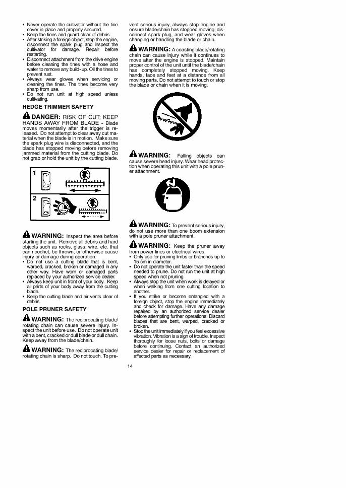
DANGER: RISK OF CUT; KEEPHANDS AWAY FROM BLADE -- Blademoves momentarily after the trigger is re-leased. Do not attempt to clear away cut ma-terial when the blade is in motion. Make surethe spark plug wire is disconnected, and theblade has stopped moving before removingjammed material from the cutting blade. Donot grab or hold the unit by the cutting blade.
WARNING: Inspect the area beforestarting the unit. Remove all debris and hardobjects such as rocks, glass, wire, etc. thatcan ricochet, be thrown, or otherwise causeinjury or damage during operation.S Do not use a cutting blade that is bent,warped, cracked, broken or damaged in anyother way. Have worn or damaged partsreplaced by your authorized service dealer.
S Always keep unit in front of your body. Keepall parts of your body away from the cuttingblade.
S Keep the cutting blade and air vents clear ofdebris.
POLE PRUNER SAFETY
WARNING: The reciprocating blade/rotating chain can cause severe injury. In-spect the unit before use. Do not operate unitwith a bent, cracked ordull bladeor dull chain.Keep away from the blade/chain.
WARNING: The reciprocating blade/rotating chain is sharp. Do not touch. To pre-
vent serious injury, always stop engine andensure blade/chain has stopped moving, dis-connect spark plug, and wear gloves whenchanging or handling the blade or chain.
WARNING: A coasting blade/rotatingchain can cause injury while it continues tomove after the engine is stopped. Maintainproper control of the unit until the blade/chainhas completely stopped moving. Keephands, face and feet at a distance from allmoving parts. Do not attempt to touch or stopthe blade or chain when it is moving.
WARNING: Falling objects cancause severe head injury. Wear head protec-tion when operating this unit with a pole prun-er attachment.
WARNING: Toprevent serious injury,do not use more than one boom extensionwith a pole pruner attachment.
WARNING: Keep the pruner awayfrom power lines or electrical wires.S Only use for pruning limbs or branches up to15 cm in diameter.
S Do not operate the unit faster than the speedneeded to prune. Do not run the unit at highspeed when not pruning.
S Always stop the unit when work is delayed orwhen walking from one cutting location toanother.
S If you strike or become entangled with aforeign object, stop the engine immediatelyand check for damage. Have any damagerepaired by an authorized service dealerbefore attempting further operations. Discardblades that are bent, warped, cracked orbroken.
S Stop theunit immediately if you feelexcessivevibration. Vibration is a sign of trouble. Inspectthoroughly for loose nuts, bolts or damagebefore continuing. Contact an authorizedservice dealer for repair or replacement ofaffected parts as necessary.
15
SNOW THROWER SAFETY
WARNING: Keep hands and feetaway from the rotor when starting or runningthe engine. Never attempt to clear the rotorwith the engine/motor running. Stop engineand disconnect spark plug before uncloggingsnow or debris from discharge chute or whenadjusting vanes.
WARNING: Never lean over dis-charge chute. Rocks or debris could bethrown into the eyes and face and cause seri-ous injury or blindness.
WARNING: Inspect the area wherethe unit is to be used. Remove objects thatcould be thrown or damage the unit. Someobjects may be hidden by fallen snow -- bealert for the possibility.S Direct material discharge away from glassenclosures, automobiles, etc.
S Do not run engine at high speed while notremoving snow.
S Be attentive when using the snowthrower,and stay alert for holes in the terrain and otherhidden hazards.
S Make sure the rotor will spin freely beforeattaching the snowthrower to the powerhead.
S If the rotor will not rotate freely due to frozenice, thaw the unit before thoroughly beforeattempting to operate under power.
S Keep the rotor clear of debris.S Do not throw snow near other people. Thesnow thrower could propel small objects athigh speed causing injury.
S After striking a foreign object, stop the engine,disconnect spark plug and inspect thesnowthrower for damage and repair ifnecessary before restarting unit.
S Never operate the snowthrower near glassenclosures, automobiles and trucks.
S Never attempt to use the snowthrower on aroof.
S Never operate the snowthrower near windowwells, dropoffs, etc.
S Never discharge snow onto public roads ornear moving traffic.
S Clear snow from slopes by going up anddown; never across. Use caution whenchanging directions. Never clear snow fromsteep slopes.
S Let snowthrower run for a few minutes afterclearing snow somoving parts do not freeze.
S Look behind and use care when backing up.Exercise caution to avoid slipping or falling,especially when operating in reverse.
S Know how to stop quickly.
MAINTENANCEThe life span of the machine can be reducedand the risk of accidents can increase if ma-chinemaintenance is not carried out correctlyand if service and/or repairs are not carriedout professionally. If you need further infor-mation, please contact your nearest autho-rised service dealer.
WARNING: Disconnect the sparkplug before performing maintenance exceptfor carburetor adjustments.CHECK FOR LOOSEFASTENERS AND PARTSS Spark Plug BootS Air FilterS Housing ScrewsS Handlebar ScrewsS Combination ShieldCHECK FOR DAMAGED ORWORN PARTSContact an authorized service dealer for re-placement of damaged or worn parts.S Fuel Tank -- Discontinue use of unit if fueltank shows signs of damage or leaks.
S Debris Shield -- Discontinue use of unit ifdebris shield is damaged.
INSPECT AND CLEAN UNIT ANDLABELSS After each use, inspect complete unit forloose or damaged parts. Clean the unit andlabels using a damp cloth with a mild deter-gent.
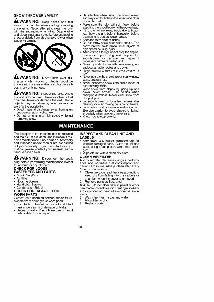
S Wipe off unit with a clean dry cloth.CLEAN AIR FILTERA dirty air filter decreases engine perform-ance and increases fuel consumption andharmful emissions. Always clean after every5 hours of operation.1. Clean the cover and the area around it to
keep dirt from falling into the carburetorchamber when the cover is removed.
2. Remove parts as illustrated.NOTE: Do not clean filter in petrol or otherflammablesolvent toavoid creatinga firehaz-ard or producing harmful evaporative emis-sions.3. Wash the filter in soap and water.4. Allow filter to dry.5. Replace parts.

16
Air filter
Air filter cover
Knob
REPLACE SPARK PLUGReplace the spark plug each year to ensurethe engine starts easier and runs better. Setspark plug gap at 0,6 mm. Ignition timing isfixed and nonadjustable.1. Twist, then pull off spark plug boot.2. Remove spark plug fromcylinder anddis-
card.3. Replace with Champion RCJ-6Y spark
plug and tighten securely with a 19 mmsocket wrench.
4. Reinstall the spark plug boot.
SERVICE AND ADJUSTMENTS
REPLACING THE LINE1. Press the tabs on the side of the trimmer
head and remove cover and spool.
TabTab
Cover
Spool
2. Remove any remaining line.3. Clean dirt and debris from all parts. Re-
place spool if it is worn or damaged.4. Replace with a pre-wound spool, or re-
place line using a 4,5 meters length of 2,4mm diameter McCulloch brand line.
WARNING: Never use wire, rope,string, etc., which canbreak off and becomeadangerous missile.5. When installing new line on an existing
spool, hold the spool as shown.6. Bend the line at the midpoint and insert
the bend into the slot in the center rim ofthe spool. Ensure line snaps into positionin the slot.
Slot
7. With your finger between the lines, wrapthe lines evenly and firmly around thespool in a clockwise direction.

17
8. Position the lines in the guide slots.
Guide slot
Guide slot
9. Place the spool in the cover as shownbelow.
10. Insert the ends of the lines through exitholes in the sides of the cover.
Line exit hole
Cover
11. Reinstall the spool and cover onto thetrimmer head. Push until cover snaps intoplace.
BLADE REPLACEMENTRefer to the ASSEMBLY section for blade re-placement instructions and illustrations.CARBURETOR ADJUSTMENT
WARNING: Keep others away whenmaking idle speed adjustments. The trimmerhead will be spinning during most of this pro-cedure. Wear your protective equipment andobserve all safety precautions. After makingadjustments, the trimmer head must notmove/spin at idle speed.The carburetor has been carefully set at thefactory. Adjustments may benecessary if younotice any of the following conditions:S Engine will not idle when the throttle is re-leased.
S The trimmer headmoves/spins at idle speed.Make adjustments with the unit supported sothe cutting attachment is off the ground andwill not make contact with any object. Holdthe unit by handwhile runningandmakingad-justments. Keep all parts of your body awayfrom the cutting attachment and muffler.Idle Speed AdjustmentAllow engine to idle. Adjust speed until engineruns without trimmer headmoving or spinning(idle speed too fast) or engine stalling (idlespeed too slow).S Turn idle speed screw clockwise to in-creaseenginespeed if enginestalls or dies.
S Turn idle speed screw counterclockwise todecrease engine speed if trimmer headmoves or spins at idle speed.
WARNING: Recheck the idle speedafter each adjustment. The trimmer headmust not move or spin at idle speed to avoidserious injury to the operator or others.

18
Air filtercover
Idle speed screwIf you require further assistanceor areunsureabout performing this procedure, contact anauthorized service dealer.
STORAGE
WARNING: Perform the followingsteps after each use:S Allow engine to cool before storing or trans-porting.
S Store unit and fuel in a well ventilated areawhere fuel vapors cannot reach sparks oropen flames from water heaters, electricmotors or switches, furnaces, etc.
S Empty fuel tank before storing or transport-ing the unit.
S Store unit and fuel well out of the reach ofchildren.
S Store unit with all guards in place. Positionunit so that any sharp object cannot acci-dentally cause injury.
SEASONAL STORAGEPrepare unit for storage at end of season or ifit will not be used for 30 days or more.If your unit is to be stored for a period of time:S Clean the entire unit before lengthy storage.S Store in a clean dry area.S Lightly oil external metal surfaces.
ENGINES Remove spark plug and pour 1 teaspoon of40:1, 2-cycle engine oil (air cooled) throughthe spark plug opening. Slowly pull thestarter rope 8 to 10 times to distribute oil.
S Replace spark plugwith new one of recom-mended type and heat range.
S Clean air filter.S Check entire unit for loose screws, nuts,and bolts. Replace any damaged, broken,or worn parts.
S At the beginning of the next season, useonly fresh fuel having the proper petrol to oilratio.
OTHERS Do not store petrol from one season toanother.
S Replace your petrol can if it starts to rust.

19
TROUBLE CAUSE REMEDYEngine will notstart.
1. Engine flooded.
2. Fuel tank empty.3. Spark plug not firing.4. Fuel not reachingcarburetor.
5. Carburetor requiresadjustment.
1. See “Starting a Flooded Engine” inOperation Section.
2. Fill tank with correct fuel mixture.3. Install new spark plug.4. Check for dirty fuel filter; replace.Check for kinked or split fuel line;repair or replace.
5. Contact an authorized service dealer.
Engine willnot idleproperly.
1. Carburetor requiresadjustment.
2. Crankshaft seals worn.3. Compression low.
1. See “Carburetor Adjustment” inService and Adjustments Section.
2. Contact an authorized service dealer.3. Contact an authorized service dealer.
1. Air filter dirty.2. Spark plug fouled.
3. Carburetor requiresadjustment.
4. Carbon build-up onmuffler outlet screen.
5. Compression low.
Engine will notaccelerate,lacks power,or dies undera load.
1. Clean or replace air filter.2. Clean or replace plugand regap.
3. Contact an authorized service dealer.
4. Contact an authorized service dealer.
5. Contact an authorized service dealer.Enginesmokesexcessively.
1. Fuel mixture incorrect.
2. Air filter dirty.3. Carburetor requiresadjustment.
1. Empty fuel tank and refill withcorrect fuel mixture.
2. Clean or replace air filter.3. Contact an authorized service dealer.
Engine runshot.
1. Fuel mixture incorrect.
2. Spark plug incorrect.3. Carburetor requiresadjustment.
4. Carbon build-up onmuffler outlet screen.
1. Empty fuel tank and refill withcorrect fuel mixture.
2. Replace with correct spark plug.3. Contact an authorized service dealer.
4. Contact an authorized service dealer.
WARNING: Always stop unit and disconnect spark plugbefore performingall of therecommended remedies below except remedies that require operation of the unit.
TROUBLESHOOTING TABLE

20
DECLARATION OF CONFORMITYEC Declaration of Conformity (Only applies to Europe)
We, Husqvarna AB, SE-561 82 Huskvarna, Sweden, tel: +46--36--146500, as authorisedrepresentative in the Community, declare that the brushcutter model McCulloch Cabrio433L with serial numbers dating from 2009 and onwards (the year is clearly stated on therating plate, followed by the serial number), comply with the requirements of theCOUNCIL’SDIRECTIVES:
of 17 May 2006 “relating to machinery” 2006/42/EC;
of 15December 2004 “relating to electromagnetic compatibility”2004/108/EC, andapplicablesupplements; and
of 8 May 2000 “relating to the noise emissions in the environment” in accordance with AnnexV of 2000/14/EC. For information relating to noise emissions, see Technical data section.
The following standards have beenapplied:EN ISO 12100-1/A1:2009,EN ISO12100-2/A1:2009,CISPR 12:2007, EN 11806:2008.
SMP, The Swedish Machinery Testing Institute, Fyrisborgsgatan 3 S--754 50 Uppsala,Sweden, has performed voluntary type examination on behalf of Husqvarna AB. Thecertificate(s) are numbered: SEC/09/2033.
09--11--01
Ronnie E. Goldman, Director of EngineeringAuthorized representative for Husqvarna AB andresponsible for technical documentation

21
TECHNICAL DATA
MODEL: Cabrio 433LENGINECylinder displacement, cm3 33At maximum engine power, rpm 7000Maximum rotational frequency of the spindle 10000Engine speed at recommended maximum spindlerotational frequency 7400Recommended speed idling, rpm 2900Maximum engine power, measured inaccordance with ISO 8893, kW 0,9Catalytic converter muffler YesIGNITION SYSTEMSpark plug Champion RCJ--6YElectrode gap, mm 0,6FUEL AND LUBRICATION SYSTEMFuel tank capacity, cm3 480WEIGHTWeight without fuel, cutting attachment and guard, kg 6,6NOISE EMISSIONS(see Note 1)Sound power level, measured dB(A) 112,3Sound power level, guaranteed LWA dB(A) 117NOISE LEVELS(see Note 2)Equivalent sound pressure level at the operators’ ear,measured according to EN/ISO 11806 and ISO 22868,dB(A)Equipped with grass blade (original) 102Equipped with trimmer head (original) 99,8VIBRATION LEVELS(see Note 3)Equivalent vibration levels (ahv,eq) at handles, measuredaccording to EN ISO 11806 and ISO 22867, m/s2
Equipped with grass blade (original), left/right 8,3/8,4Equipped with trimmer head (original), left/right 6,4/8,1
Note 1: Noise emissions in the environment measured as sound power (LWA) in conformitywith EC directive 2000/14/EC. Reported sound power level for the machine has beenmeasured with the original cutting attachment that gives the highest level. The differencebetween guaranteed and measured sound power is that the guaranteed sound power alsoincludes dispersion in the measurement result and the variations between different machinesof the same model according to Directive 2000/14/EC.
Note 2: Reported data for equivalent sound pressure level for the machine has a typicalstatistical dispersion (standard deviation) of 1 dB(A).
Note 3: Reported data for equivalent vibration level has a typical statistical dispersion(standard deviation) of 1 m/s2.
Model Cabrio 433L (3/8 LH arbor shaft thread)Centre hole in blades/cutters,∅ 25,4 mm
Approved accessories Type Cutting attachment /guard, part. no.
Grass blade/grass cutter Grass (∅ 20 cm, 4--teeth) 530 05 58 92 / 575 35 27 01
Trimmer head TNG7 (∅ 2,4 mm line) 537 41 92--02 / 575 35 27 01