okidata fax 2200, 2400,2600 service manual
DESCRIPTION
Service Manual for Okidata Fax 2200, 2400, 2600TRANSCRIPT

Page: 1
Service Guide OF2200/2400/2600Chapter 0 About This Manual
OKIFAX 2200 // 2400 // 2600Facsimile Products
Adobe Acrobat printable reference copy of the OKIDATA Service Training Manual.
09/17/97
Note: This Adobe Acrobat version of the Okidata Service Training Manual was built with the pictures rendered at 300 dpi, which is ideal for printing, but does not view on most displays well.
Copyright 1997, Okidata, Division of OKI America, Inc. All rights reserved. See the OKIDATA Business Partner Exchange (BPX) for any updates to this material. (http://bpx.okidata.com)
Table of Contents Page
Service Guide OF2200/2400/26000 About This Manual
Front Cover 1Copyright 2
1 Principles of Operation1.1 Principles Of Operation 3....1.1.01 Compatibility 4....1.1.02 Communications Mode 5....1.1.03 Modem Operation 6....1.1.04 Automatic Fall-Back Mode 7....1.1.05 Telephone Line Connection 8....1.1.06 Error Correction Mode (ECM) 9....1.1.07 Quick Scan Mode 10....1.1.08 Major Assemblies (Mechanical) - Cross-Section Diagram
11
....1.1.09 Major Assemblies (Electrical) 12
........Okifax 2200 - Copy Function Block Diagram 13
........Okifax 2400/2600 - Copy Function Block Diagram 14
........Okifax 2200 - Report Print Function Block Diagram 15
........Okifax 2400/2600 - Report Print Function Block Diagram 161.2 Transmitter Theory Of Operation 17........Okifax 2200 - 300 Bps Transmit Handshake Operation Diagram
18
........Okifax 2400/2600 - 300 Bps Transmit Handshake Operation Diagram
19
........Okifax 2200 - 300 Bps Receive Handshake Operation Diagram
20
........Okifax 2400/2600 - 300 Bps Receive Handshake Operation Diagram
21
........Okifax 2200 - G3 Transmit Functional Block Diagram 22
........Okifax 2400/2600 - G3 Transmit Functional Block Diagram 23
....1.2.02 Operator Panel Assembly (OPE) 24
....1.2.03 Automatic Document Feeder (ADF) 25
....1.2.04 Scanner Assembly 26
....1.2.05 Encoder 27
....1.2.06 Modem 28
....1.2.07 Network Control Unit (NCU) 29
....1.2.08 Line Interface Board 301.3 Receiver Theory Of Operation 31........Okifax 2200 - G3 Receive Operation Block Diagram 32........Okifax 2400/2600 - G3 Receive Operation Block Diagram 331.4 Led Printer - Principal Components 341.5 Printing Process - General Information 35....1.5.02 The Full Printing Process 36

Table of Contents Page
1.6 Sensors And Switches 37....Paper Inlet Jam 38....Paper Feed Jam 39....1.6.02 Toner Low Sensor 40
2 Failure Analysis2.1 Overview 412.2 Troubleshooting Updates 422.3 Reporting Problems 432.4 Troubleshooting Tips 442.5 Repair Analysis Procedures 45....2.5.02 RAP Index 46....Start Here Flowchart 47........RAP 01 No LCD Display 48........RAP 02 Alarm Led Is Lit 49........RAP 03 Print Test Failure 50........RAP 04 Local Copy Problem 51............Checking PC1 And PC2 52........RAP 05 Auto Dial Problem 53........RAP 06 Data Transmission Problem 54........RAP 07 Auto Reception Problem 55........RAP 08 Reception Problem 56........RAP 09 Scan Operation Test Failure 57........RAP 10 LED Test Failure 58........RAP 11 Tone Send Test Failure 59........RAP 12 High Speed Modem Test Failure 60........RAP 13 Multi-Frequency Send Test Failure 61........RAP 14 Voice Message Test Failure 62........RAP 15 No Acoustic Line Monitor 63........RAP 16 Document Does Not Feed 64........RAP 17 Multiple Document Feeds 65........RAP 18 Document Skews 66........RAP 19 Document Jams 67........RAP 20 Problems Shown On LCD Display 68............RAP 20A Cover Open 69............RAP 20B Printer Alarm 1 70............RAP 20C Printer Alarm 2 71............RAP 20D Printer Alarm 3 72............RAP 20E Printer Alarm 4 73............RAP 20F Paper Jam 74............RAP 20G No Paper Cassette 75............ Action Items For LCD Display Problems 76........RAP 21 Image Problems 77............RAP 21A Poor Print Quality (Images Light Or Blurred As A Whole)
78

Table of Contents Page
............RAP 21B Dark Background Density 79
............RAP 21C Printed Output Is Blank 80
............RAP 21D Vertical Black Stripes On Printed Output 81
............RAP 21E Repetitive Spaced Marks On Printed Output 82
............RAP 21F Vertical White Streaks On Printed Output 83
............RAP 21G Areas Missing From Printed Output 84
............RAP 21H Poor Fusing 852.6 Tests 86....2.6.01 Self-Diagnosis 87....2.6.02 Sensor Calibration / Scanning Check 88....2.6.03 LED Test 89....2.6.04 Tone Test 90....2.6.05 High-Speed Modem Transmit Test 91....2.6.06 High-Speed Modem Receive Test 92....2.6.07 Multi-Frequency Send Test 93....2.6.08 Print Test 94....2.6.09 Voice Message Test 952.7 Reports - General Information 96....2.7.02 Service Codes List (Activity Report) 97....2.7.03 Protocol Dump 98........Facsimile Control Field Conversion Table 992.8 Resets 100....2.8.01 General Information 101....2.8.02 Toner Counter Reset 102....2.8.03 Drum Counter Reset 103....2.8.04 Fuser Counter Reset 104....2.8.05 System Reset 1052.9 Technical Function Settings 106....List Of Technical Functions - Okifax 2200 107....List Of Technical Functions - Okifax 2400/2600 108....2.9.02 Service Bit / Service Parameter 109........Bit Assignments Table 1102.10 Tel / Fax Automatic Switching 1112.11 Touch Tone Mode 1122.12 Dialing Parameters 1132.13 User Functions 114....2.13.02 Dual Access Combination Table - Okifax 2400/2600 1152.14 General Operation Diagrams 116
3 Disassembly & MaintenanceDisassembly & Maintenance - General Information 1173.2 Disassembly/Assembly Procedures 118....3.2.01 Preliminary Items 119....3.2.02 Doc. Stay Guide Assembly; Rear And Terminal Cap Covers
120

Table of Contents Page
....3.2.03 Right Side Cover And Speaker 121
....3.2.04 Network Control Unit 122
....3.2.05 Left Side Cover Assembly 123
....3.2.06 Cradle Assembly 124
....3.2.07 Hook Switch Board 125
....3.2.08 Memory Board 126
....3.2.09 Control Panel Assembly And Paper Guide (U) 127
....3.2.10 Feed, Pinch Roller; Tension Arm; Adf Spring, B-Up Plate
128
....3.2.11 Separation Rubber 129
....3.2.12 Cover (U) 130
....3.2.13 ADF, SUB, And Sensor Rollers; Paper Guide & Releases
131
....3.2.14 Verification Stamp, Paper Guide (E), And Feed Roller(2)
132
....3.2.15 Contact Image Sensor Assembly 133
....3.2.16 Gear Frame Assembly And Scan Motor 134
....3.2.17 PC-1, PC-2, And Pinch Roller 135
....3.2.18 Release Guide Assembly And Sub-Cover (Right) 136
....3.2.19 Main Control Board, Second Tray Interface Board 137
....3.2.20 Lower Base Assembly 138
....3.2.21 Stacker Cover And Led Head 139
....3.2.22 Feed Guide, Eject Roller, And Fusing Unit Assemblies
140
....3.2.23 Motor Assembly, Resist Motor, And Main Motor 141
....3.2.24 Pressure & Transfer Rollers, Idle Gears, Cover Open Arm, Reset Levers
142
....3.2.25 Registration Roller, Sensor Plates, Damper Cover Arm, Gear
143
....3.2.26 Line Board And Network Control Board 144
....3.2.27 Printer Control Board And Fan 145
....3.2.28 PS Board, Cassette Tray Assm., & Cassette Sensor Plate
146
3.3 Adjustments And Service Settings 1473.4 Cleaning 1483.5 Lubrication 149
A Board DiagramsBoard Diagrams 150A.2 Index To Charts 151....A.2.01 Main Control Board (MCNT-250) Okifax 2200 152....A.2.02 Main Control Board (DFCU) Okifax 2400/2600 153....A.2.03 Printer Control Board (PCNT-250) Okifax 2200 154....A.2.04 Printer Control Board (DFPU) Okifax 2400/2600 155....A.2.05 Network Control Unit (NCU) 156

Table of Contents Page
....A.2.06 Power Supply Board (PWU) 157
....A.2.07 Memory Board (MT-25) Okifax 2200 158
....A.2.08 Memory Board (DFME) Okifax 2400/2600 159
....A.2.09 Line Interface Board (LINE) 160
....A.2.10 Connector Board (CB-250) 161
....A.2.11 Interconnect Diagrams (2200) 162
........Okifax 2200 - 2 Of 5 163
........Okifax 2200 - 3 Of 5 164
........Okifax 2200 - 4 Of 5 165
........Okifax 2200 - 5 Of 5 166
....A.2.12 Interconnect Diagrams (2400/2600) - 1 Of 6 167
........Okifax 2400/2600 - 2 Of 6 168
........Okifax 2400/2600 - 3 Of 6 169
........Okifax 2400/2600 - 4 Of 6 170
........Okifax 2400/2600 - 5 Of 6 171
........Okifax 2400/2600 - 6 Of 6 172B Illustrated Parts
B.1 Illustrated Parts Listing - General Information 173....B.1.02 Definitions Of Terms 174....B.1.03 Parts Ordering Information 175B.2 Charts 176....B.2.01 Cabinet Assembly (1 Of 2) 177....B.2.02 Cabinet Assembly (2 Of 2) 178....B.2.03 Control Panel Assembly (Okifax 2200) 179....B.2.04 Control Panel Assembly (Okifax 2400/2600) 180....B.2.05 Printer Assembly (1 Of 3) 181....B.2.06 Printer Assembly (2 Of 3) 182....B.2.07 Printer Assembly (3 Of 3) 183....B.2.08 Base Assembly (1 Of 2) 184....B.2.09 Base Assembly (2 Of 2) 185....B.2.10 Scan Assembly (1 Of 2) 186....B.2.11 Scan Assembly (2 Of 2) 187....B.2.12 Scan Unit (1 Of 3) 188....B.2.13 Scan Unit (2 Of 3) 189....B.2.14 Scan Unit (3 Of 3) 190....B.2.15 Upper Paper Guide Assembly (1 Of 2) 191....B.2.16 Upper Paper Guide Assembly (2 Of 2) 192....B.2.17 Cables 193....B.2.18 Options 194....B.2.19 Packaging 195....B.2.20 Consumables 196....B.2.21 Documentation 197B.2.3 UST-500 Illustrated Parts List 198....B.2.31 Assembly View 199

Table of Contents Page
....B.2.32 Section 1: Cabinet Assembly 200
....B.2.33 Section 2: Mechanical Unit 201
....B.2.34 Section 3: Cassette Assembly 202C Installation of Options
C.1 Overview 203C.2 Option Installation 204....C.2.02 UST-500 (Second Paper Cassette Unit) 205........UST-500 Testing Procedure 206....C.2.03 SIO-45 Board (RS232-C Interface) 207C.3 Telephone Answering Device (TAD) Interface 208

Page: 2
Service Guide OF2200/2400/2600Chapter 0 About This Manual
This document may not be reproduced without the written permission of the Okidata® Sales and Product Training Group. Every effort has been made to ensure the accuracy of the information contained in this training course. Okidata is not responsible for errors beyond its control.
© 1994 by Okidata All rights reserved.
First Edition January, 1994
Second Edition July, 1994
Written and produced by the Okidata Sales and Product Training
Please send any comments on this publication to the address listed below.
Okidata
Sales and Product Training
532 Fellowship Road
Mount Laurel, NJ 08054-3499
Facsimile Number: (609) 235-2600, ext. 7034.
Okilink Login Name: Technical Training
OKI is a registered trademark of Oki Electric Industry Company, Ltd.; marques deposee de Oki Electric Industry Company, Ltd.; marca registrada, Oki Electric Industry Company, Ltd.
OKIDATA is a registered trademark of Oki Electric Industry Company, Ltd.; marques deposee de Oki Electric Industry Company, Ltd.; marca registrada, Oki Electric Industry Company, Ltd.
OKIFAX is a registered trademark of Oki Electric Industry Company, Ltd.; marques deposee de Oki Electric Industry Company, Ltd.; marca registrada, Oki Electric Industry Company, Ltd.
Touch Tone is a registered trademark of American Telephone and Telegraph
Copyright 1997, Okidata, Division of OKI America, Inc. All rights reserved. See the OKIDATA Business Partner Exchange (BPX) for any updates to this material. (http://bpx.okidata.com)

Page: 3
Service Guide OF2200/2400/2600Chapter 1 Principles of Operation
1.1 PRINCIPLES OF OPERATION
This module contains three sections.
· Transmitter Theory of Operation
· Receiver Theory of Operation
· LED Printer Theory of Operation
Copyright 1997, Okidata, Division of OKI America, Inc. All rights reserved. See the OKIDATA Business Partner Exchange (BPX) for any updates to this material. (http://bpx.okidata.com)

Page: 4
Service Guide OF2200/2400/2600Chapter 1 Principles of Operation
1.1.01 Compatibility
The facsimile machine operates as a Group 3 (G3) facsimile device.
Copyright 1997, Okidata, Division of OKI America, Inc. All rights reserved. See the OKIDATA Business Partner Exchange (BPX) for any updates to this material. (http://bpx.okidata.com)

Page: 5
Service Guide OF2200/2400/2600Chapter 1 Principles of Operation
1.1.02 Communications Mode
The unit operates as a half-duplex facsimile transceiver. Transmit and receive operations cannot take place at the same time. However, documents can be prepared for transmission while the machine is engaged in message reception. These documents will be automatically transmitted upon completion of the receiving operation.
Copyright 1997, Okidata, Division of OKI America, Inc. All rights reserved. See the OKIDATA Business Partner Exchange (BPX) for any updates to this material. (http://bpx.okidata.com)

Page: 6
Service Guide OF2200/2400/2600Chapter 1 Principles of Operation
1.1.03 Modem Operation
The high-speed modem conforms to the following standards.
· CCITT Standard V.29 for 9600/7200 bps (bits per second) operation
· CCITT Standard V.27 ter. for 4800/2400 bps operation
· CCITT Standard for V.17 14400/12000 bps (Okifax 2400, 2600 only)
· CCITT Standard for V.33 14400/12000 bps (Okifax 2400, 2600 only)
The low-speed (300 bps) modem, which is used for handshaking, conforms to CCITT standard V.21 Channel 2 or equivalent.
Copyright 1997, Okidata, Division of OKI America, Inc. All rights reserved. See the OKIDATA Business Partner Exchange (BPX) for any updates to this material. (http://bpx.okidata.com)

Page: 7
Service Guide OF2200/2400/2600Chapter 1 Principles of Operation
1.1.04 Automatic Fall-back Mode
The unit will change the message transmitting speed according to the following fall-back plan. The first page of the message is transmitted at 14.4 kbps (Okifax 2200 communicates at 9600 bps maximum). The receiving station will continuously monitor the received data. If the receiving station detects six or more consecutive error lines during reception of a single page, or if the total number of errors detected during the reception of a single page exceeds 10% of the data on the transmitted page, it will return a Retrain Negative (RTN) signal to the transmitting station upon termination of the page reception. With an RTN signal received, the transmitting station will downgrade its speed by one level (to 12 kbps in this case) and continue transmission of the next page. Similarly, should the transmitting station again receive an RTN signal from the receiving station, it will downgrade the speed another level.
Copyright 1997, Okidata, Division of OKI America, Inc. All rights reserved. See the OKIDATA Business Partner Exchange (BPX) for any updates to this material. (http://bpx.okidata.com)

Page: 8
Service Guide OF2200/2400/2600Chapter 1 Principles of Operation
1.1.05 Telephone Line Connection
The facsimile machine is connected to the telephone line via the line interface board. Two RJ-11 connectors are provided. One connects to the telephone line. The other connects to an external telephone. A separate modular jack is provided for connection of the handset.
The unit will control the switching between the handset (or the external telephone) and the telephone line to permit use of the handset or telephone for voice communication.
Copyright 1997, Okidata, Division of OKI America, Inc. All rights reserved. See the OKIDATA Business Partner Exchange (BPX) for any updates to this material. (http://bpx.okidata.com)

Page: 9
Service Guide OF2200/2400/2600Chapter 1 Principles of Operation
1.1.06 Error Correction Mode (ECM)
Error Correction Mode (ECM) provides error-free transmission when communicating with a remote unit that also has ECM.
Here is an explanation of the ECM process.
· The transmit machine groups image data into blocks and transmits one block of data at a time to the receive machine. At the end of each block, a Partial Page Signal (PPS) is transmitted.
· The receive machine stores the data block in memory and checks each frame within that block for errors.
Modified Huffman assigns a binary code to consecutive recurring bits of white or black. The codes must add up to a total of 1728 bits, which is the Main Scan Rate established by CCITT.
Modified Read uses a comparison technique. The line being coded is compared to the previous line and differences are noted. Codes are then assigned to reflect the differences between the two lines.
· If no errors are detected, the receiver sends Message Confirmation (MCF). MCF requests the transmit machine to transmit the next data block.
· If an error is detected by the receive machine, the receive machine will transmit the frame number of the defective frame back to the transmit machine in a signal called Partial Page Request (PPR).
· The transmit machine will then re-transmit the frame to the receive machine as a Partial Page.
· The receive machine rechecks the Partial Page, and (if all frames are correct) the receive machine transmits MCF.
· The next data block is transmitted.
Copyright 1997, Okidata, Division of OKI America, Inc. All rights reserved. See the OKIDATA Business Partner Exchange (BPX) for any updates to this material. (http://bpx.okidata.com)

Page: 10
Service Guide OF2200/2400/2600Chapter 1 Principles of Operation
1.1.07 Quick Scan Mode
Both the Okifax 2400 and Okifax 2600 have quick scan capability. With MEM Transmission enabled, the units will scan documents placed on the ADF tray into memory. During a quick scan operation, each letter size page is scanned in approximately three seconds. Once the documents are stored in memory, the transmission is initiated, without requiring additional user action.
· Okifax 2200 Quick Scan = 7.6 seconds per page (@ Standard Resolution)
· Okifax 2400 Quick Scan = 6.0 seconds per page (@ Standard Resolution)
· Okifax 2600 Quick Scan = 3.0 seconds per page (@ Standard Resolution)
Copyright 1997, Okidata, Division of OKI America, Inc. All rights reserved. See the OKIDATA Business Partner Exchange (BPX) for any updates to this material. (http://bpx.okidata.com)

Page: 11
Service Guide OF2200/2400/2600Chapter 1 Principles of Operation
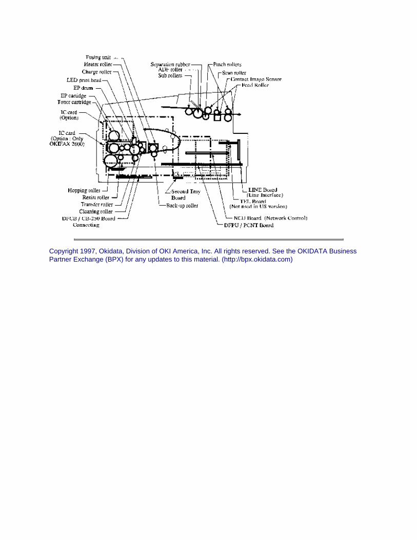
1.1.08 Major Assemblies (Mechanical)
The following major mechanical assemblies make up the facsimile machine.
· Automatic Document Feeder (ADF) Unit / Scan Unit· Printer Unit
Copyright 1997, Okidata, Division of OKI America, Inc. All rights reserved. See the OKIDATA Business Partner Exchange (BPX) for any updates to this material. (http://bpx.okidata.com)

Page: 12
Service Guide OF2200/2400/2600Chapter 1 Principles of Operation
1.1.09 Major Assemblies (Electrical)
The following major electrical assemblies make up the facsimile machine.
· Main Control Board (DFCU / MCNT)
· Printer Control Board (DFPU / PCNT)
· Network Control Board (NCU)
· Operator Panel Assembly Not Shown
· Power Supply Unit Not Shown
· Memory Board Not Shown
· Line Interface Board Not Shown
· Hook Switch Board Not Shown
· Connecting Board
· Second Paper Tray Mechanism Board
Copyright 1997, Okidata, Division of OKI America, Inc. All rights reserved. See the OKIDATA Business Partner Exchange (BPX) for any updates to this material. (http://bpx.okidata.com)

Page: 13
Service Guide OF2200/2400/2600Chapter 1 Principles of Operation
Okifax 2200 - Copy Function Block Diagram
Copyright 1997, Okidata, Division of OKI America, Inc. All rights reserved. See the OKIDATA Business Partner Exchange (BPX) for any updates to this material. (http://bpx.okidata.com)

Page: 14
Service Guide OF2200/2400/2600Chapter 1 Principles of Operation
Okifax 2400/2600 - Copy Function Block Diagram
Copyright 1997, Okidata, Division of OKI America, Inc. All rights reserved. See the OKIDATA Business Partner Exchange (BPX) for any updates to this material. (http://bpx.okidata.com)

Page: 15
Service Guide OF2200/2400/2600Chapter 1 Principles of Operation
Okifax 2200 - Report Print Function Block Diagram
Copyright 1997, Okidata, Division of OKI America, Inc. All rights reserved. See the OKIDATA Business Partner Exchange (BPX) for any updates to this material. (http://bpx.okidata.com)

Page: 16
Service Guide OF2200/2400/2600Chapter 1 Principles of Operation
Okifax 2400/2600 - Report Print Function Block Diagram
Copyright 1997, Okidata, Division of OKI America, Inc. All rights reserved. See the OKIDATA Business Partner Exchange (BPX) for any updates to this material. (http://bpx.okidata.com)
Page: 17
Service Guide OF2200/2400/2600Chapter 1 Principles of Operation
1.2 TRANSMITTER THEORY OF OPERATION
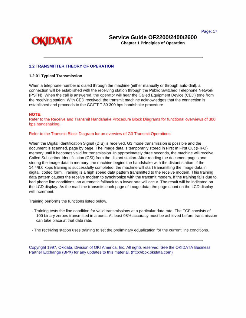
1.2.01 Typical Transmission
When a telephone number is dialed through the machine (either manually or through auto-dial), a connection will be established with the receiving station through the Public Switched Telephone Network (PSTN). When the call is answered, the operator will hear the Called Equipment Device (CED) tone from the receiving station. With CED received, the transmit machine acknowledges that the connection is established and proceeds to the CCITT T.30 300 bps handshake procedure.
NOTE:Refer to the Receive and Transmit Handshake Procedure Block Diagrams for functional overviews of 300 bps handshaking.
Refer to the Transmit Block Diagram for an overview of G3 Transmit Operations
When the Digital Identification Signal (DIS) is received, G3 mode transmission is possible and the document is scanned, page by page. The image data is temporarily stored in First In First Out (FIFO) memory until it becomes valid for transmission. In approximately three seconds, the machine will receive Called Subscriber Identification (CSI) from the distant station. After reading the document pages and storing the image data in memory, the machine begins the handshake with the distant station. If the 14.4/9.6 kbps training is successfully completed, the machine will start transmitting the image data in digital, coded form. Training is a high speed data pattern transmitted to the receive modem. This training data pattern causes the receive modem to synchronize with the transmit modem. If the training fails due to bad phone line conditions, an automatic fallback to a lower rate will occur. The result will be indicated on the LCD display. As the machine transmits each page of image data, the page count on the LCD display will increment.
Training performs the functions listed below.
· Training tests the line condition for valid transmissions at a particular data rate. The TCF consists of 100 binary zeroes transmitted in a burst. At least 98% accuracy must be achieved before transmission can take place at that data rate.
· The receiving station uses training to set the preliminary equalization for the current line conditions.
Copyright 1997, Okidata, Division of OKI America, Inc. All rights reserved. See the OKIDATA Business Partner Exchange (BPX) for any updates to this material. (http://bpx.okidata.com)

Page: 18
Service Guide OF2200/2400/2600Chapter 1 Principles of Operation
Okifax 2200 - 300 bps Transmit Handshake Operation Diagram
Copyright 1997, Okidata, Division of OKI America, Inc. All rights reserved. See the OKIDATA Business Partner Exchange (BPX) for any updates to this material. (http://bpx.okidata.com)

Page: 19
Service Guide OF2200/2400/2600Chapter 1 Principles of Operation
Okifax 2400/2600 - 300 bps Transmit Handshake Operation Diagram
Copyright 1997, Okidata, Division of OKI America, Inc. All rights reserved. See the OKIDATA Business Partner Exchange (BPX) for any updates to this material. (http://bpx.okidata.com)

Page: 20
Service Guide OF2200/2400/2600Chapter 1 Principles of Operation
Okifax 2200 - 300 bps Receive Handshake Operation Diagram
Copyright 1997, Okidata, Division of OKI America, Inc. All rights reserved. See the OKIDATA Business Partner Exchange (BPX) for any updates to this material. (http://bpx.okidata.com)

Page: 21
Service Guide OF2200/2400/2600Chapter 1 Principles of Operation
Okifax 2400/2600 - 300 bps Receive Handshake Operation Diagram
Copyright 1997, Okidata, Division of OKI America, Inc. All rights reserved. See the OKIDATA Business Partner Exchange (BPX) for any updates to this material. (http://bpx.okidata.com)
Page: 22
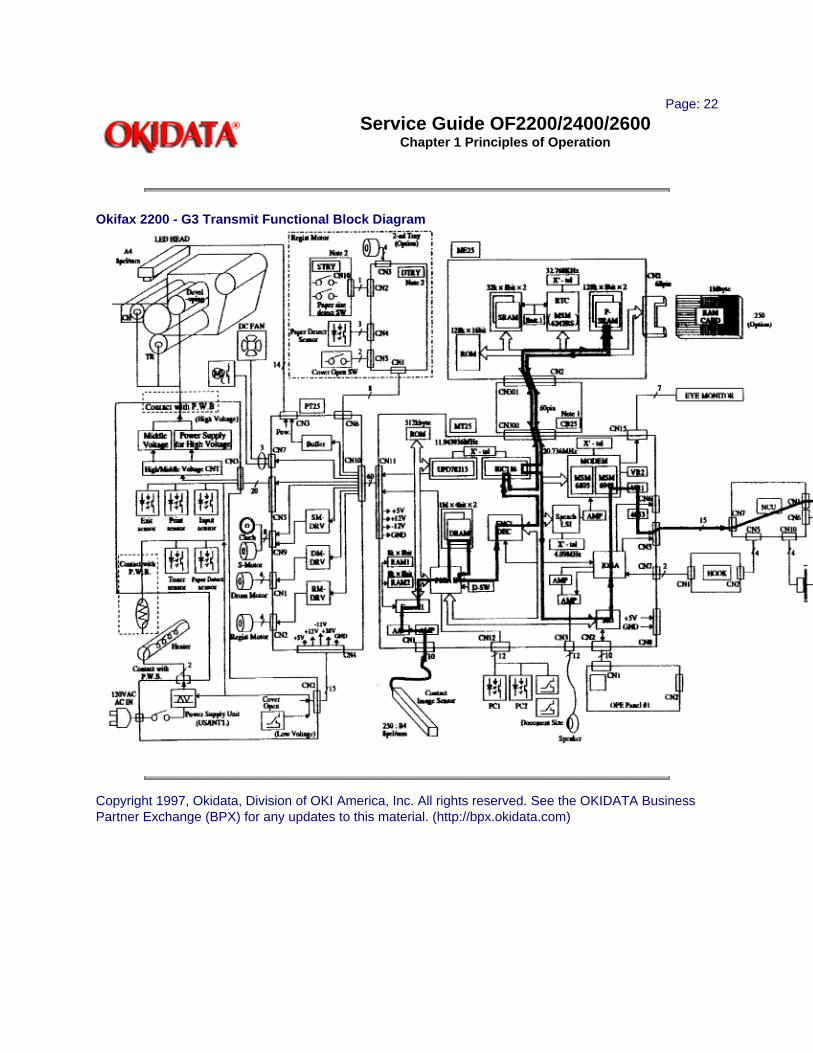
Service Guide OF2200/2400/2600Chapter 1 Principles of Operation
Okifax 2200 - G3 Transmit Functional Block Diagram
Copyright 1997, Okidata, Division of OKI America, Inc. All rights reserved. See the OKIDATA Business Partner Exchange (BPX) for any updates to this material. (http://bpx.okidata.com)

Page: 23
Service Guide OF2200/2400/2600Chapter 1 Principles of Operation
Okifax 2400/2600 - G3 Transmit Functional Block Diagram
Copyright 1997, Okidata, Division of OKI America, Inc. All rights reserved. See the OKIDATA Business Partner Exchange (BPX) for any updates to this material. (http://bpx.okidata.com)

Page: 24
Service Guide OF2200/2400/2600Chapter 1 Principles of Operation
1.2.02 Operator Panel Assembly (OPE)
Through the operator panel assembly, the end user initiates transmit and receive operations, sets desired options, programs telephone numbers and other data, and interfaces in all areas of the operation of the machine. The panel consists of an LCD display (two rows of 20 characters), a numeric key pad, nine LED indicators, and function keys. The functions of the keys and indicators are described in the Users Documentation.
Copyright 1997, Okidata, Division of OKI America, Inc. All rights reserved. See the OKIDATA Business Partner Exchange (BPX) for any updates to this material. (http://bpx.okidata.com)

Page: 25
Service Guide OF2200/2400/2600Chapter 1 Principles of Operation
1.2.03 Automatic Document Feeder (ADF)
The automatic document feeder transfers document sheets to the scan unit automatically, one at a time. The following diagram shows the mechanism used for detecting the leading and trailing edges of a document.
When a document is placed on the feeder, it is sensed by the document detect sensor (PC1). This causes the feed rollers to activate, feeding the document. The document is fed to the PC2 lever, where the leading edge of the document is detected. When transmit (or copy) begins, the document is fed by the transmit stepper motor to the start scan position. The documents trailing edge is detected when the PC2 lever is released. If another document is on the feeder, the process is repeated.
The Okifax 2200/2400/2600 also contain a B4 paper width sensor (PC1). The Okifax 2600 has an additional photosensor (PC1) to detect A3 paper width.
The separation rubber holds back the top originals and allows only one document to be fed into the scanner area. The separation rubber and automatic document feed rollers should be cleaned or replaced according to the cleaning schedule (in Module 3 of this manual) to assure proper operation.
The automatic document feed capacity is 50 pages of 20 pound paper. Place documents (on the feeder) image side DOWN. When feeding multiple pages, the bottom page is fed first, working toward the top.
Copyright 1997, Okidata, Division of OKI America, Inc. All rights reserved. See the OKIDATA Business Partner Exchange (BPX) for any updates to this material. (http://bpx.okidata.com)

Page: 26
Service Guide OF2200/2400/2600Chapter 1 Principles of Operation
1.2.04 Scanner Assembly
The Okifax 2200 and 2400 use a 2048-bit element direct contact type image scanning sensor. The Okifax 2600 uses a 2432-bit element direct contact image scanning sensor. LEDs are located at the bottom of the scan glass and image sensors are located at the top of the glass. When the document reaches the scanning unit, it passes directly in front of the image sensor. The LEDs illuminate the document and the light reflects back to the image sensors. This image data is sent to the printer control board via the main control board. The transmitted document length is limited to 14 inches; however, the machine can be modified for longer transmissions. (See Transmitting Long Documents in the Users Documentation).
Transmission will stop and a line disconnect will occur if the end of the document is not detected within 14 inches after scanning begins (unless the unit is set for unlimited transmission.) This message will be displayed if the document does not reach the scanning position within five seconds after the start of a document feed.
Okifax 2200 RELOAD DOCUMENTCONFIRM AND "STOP"
Okifax 2400/2600 (DATE/TIME, RX MODE)REMOVE DOCUMENT AND "STOP"
NOTE:When a jam condition is displayed on the operator panel during message transmission, the machine will stop, but its receiving capability will remain active.
Copyright 1997, Okidata, Division of OKI America, Inc. All rights reserved. See the OKIDATA Business Partner Exchange (BPX) for any updates to this material. (http://bpx.okidata.com)

Page: 27
Service Guide OF2200/2400/2600Chapter 1 Principles of Operation
1.2.05 Encoder
Scanned image data received by the board is sent to the encoder/decoder (ENC/DEC) integrated chip of the main control board. The image data is compressed by the ENC/DEC according to the Modified Huffman (MH) and Modified Read (MR) encoding scheme, or MH only. The use of MH only or both MH and MR is determined by a function setting. Data is then stored in the FIFO area in one byte units. Fill bits are inserted if the length of one encoded line is less than the minimum scan time of the remote unit. Data is transferred to the network control unit, then sent to the line interface board for transmission over the phone line.
Copyright 1997, Okidata, Division of OKI America, Inc. All rights reserved. See the OKIDATA Business Partner Exchange (BPX) for any updates to this material. (http://bpx.okidata.com)
Page: 28
Service Guide OF2200/2400/2600Chapter 1 Principles of Operation
1.2.06 Modem
The modem, located on the main control board, modulates the data in the correct G3 (14.4, 12, 9.6, 7.2, 4.8, or 2.4K bps) data rate that was determined during handshaking between the local machine and the remote receiver. Modulation is the process of converting the digital output of the scanner into an analog signal that can be transmitted over the telephone system.
Copyright 1997, Okidata, Division of OKI America, Inc. All rights reserved. See the OKIDATA Business Partner Exchange (BPX) for any updates to this material. (http://bpx.okidata.com)

Page: 29
Service Guide OF2200/2400/2600Chapter 1 Principles of Operation
1.2.07 Network Control Unit (NCU)
The network control unit receives the modulated data from the main control board and transfers the data to the line interface board.
The network control unit performs the following functions during the transmit operation.
· Unit connection / disconnection to the telephone line via the CML Relay
· Dial pulse generation
· PIS tone detection
· OFF-HOOK detection (Line Current Detector)
· TX output signal attenuation (normally 9 decibel output)
· Separation of the TX and RX signals (performed by the Hybrid Transformer)
· Impedance matching (the 600 ohm impedance of the telephone line)
Copyright 1997, Okidata, Division of OKI America, Inc. All rights reserved. See the OKIDATA Business Partner Exchange (BPX) for any updates to this material. (http://bpx.okidata.com)

Page: 30
Service Guide OF2200/2400/2600Chapter 1 Principles of Operation
1.2.08 Line Interface Board
The line interface board provides the RJ-11 connection used to transmit data to the PSTN, PBX, or Leased Line.
Copyright 1997, Okidata, Division of OKI America, Inc. All rights reserved. See the OKIDATA Business Partner Exchange (BPX) for any updates to this material. (http://bpx.okidata.com)
Page: 31
Service Guide OF2200/2400/2600Chapter 1 Principles of Operation
1.3 RECEIVER THEORY OF OPERATION
1.3.01 Operator PanelThrough the operator panel, the user initiates manual receive operations and sets auto-answer options.
1.3.02 Line Interface BoardThe line interface board provides the RJ-11 connection used to receive data from the PSTN, PBX, or Leased Line.
1.3.03 Network Control Board (NCU)The network control unit receives the modulated data from the line interface board and sends it to the modem (located on the main control board). The operation of the network control unit in the receive mode is very similar to the transmit mode. However, during receive operations, the network control unit also functions as an amplifier for the received signal.
1.3.04 ModemThe modem demodulates the data from the G3 (14.4, 12, 9.6, 7.2, 4.8, or 2.4K bps) scheme that was determined during handshaking. The data is then sent to the RAM memory for temporary storage. The storage time is dependent on whether the machine is printing real-time or from memory.
1.3.05 DecoderThe decoder decodes the MH, MR, or MMR data from the RAM into lines of picture data that are 1,728 bits in length. After the data has been received, demodulated, and decoded, it is transferred to the printer control board.
1.3.06 Document SizeSince the available printing area of the printer is smaller than the paper size, document contents may be missed on both sides of the paper, or a document image having the same length as the printing paper may be split into separate pages during printing. To prevent this, the unit automatically sets the proper reduction ratio within the range of 76 to 100% if the RX REDUCTION function has been set ON. If a received document image is longer than the available printing length, the excess part of the image is eliminated. If the SPLIT PRINT function has been set ON, the excess image will be printed on the next page.
Copyright 1997, Okidata, Division of OKI America, Inc. All rights reserved. See the OKIDATA Business Partner Exchange (BPX) for any updates to this material. (http://bpx.okidata.com)

Page: 32
Service Guide OF2200/2400/2600Chapter 1 Principles of Operation
Okifax 2200 - G3 Receive Operation Block Diagram
Copyright 1997, Okidata, Division of OKI America, Inc. All rights reserved. See the OKIDATA Business Partner Exchange (BPX) for any updates to this material. (http://bpx.okidata.com)
Page: 33
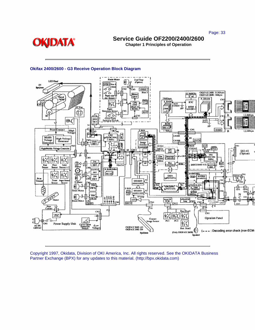
Service Guide OF2200/2400/2600Chapter 1 Principles of Operation
Okifax 2400/2600 - G3 Receive Operation Block Diagram
Copyright 1997, Okidata, Division of OKI America, Inc. All rights reserved. See the OKIDATA Business Partner Exchange (BPX) for any updates to this material. (http://bpx.okidata.com)

Page: 34
Service Guide OF2200/2400/2600Chapter 1 Principles of Operation
1.4 LED PRINTER
1.4.01 Principal ComponentsThe principal hardware components of the printer unit are listed below.
· Printer Control Board
· Power Supply Unit
· Fuser Unit
· Main Motor
· LED Head
· Registration Motor
· DC Fan
· Second Paper Tray Mechanism (option)
1.4.02 Printer Control BoardThe printer control board contains a printer unit gate array, 7.5 megahertz microprocessor, send motor driver (transistor array), registration motor driver integrated circuit, drum motor driver integrated circuit, and fan motor driver transistors.
This board controls the paper feed and paper transport functions. It also activates the LED array diodes, which leave a latent electrostatic image on the photosensitive drum. This latent image is printed by fusing toner to the paper.
1.4.03 Power Supply UnitThe power supply is a switching-type unit, which generates the following voltages from the AC input voltage.
· + 5 vdc : Printer Logic
· + / - 12 vdc: Interface Signal Levels
· + 38 vdc: Transmit Stepper Motor, Registration / Drum Motor Drive, Fan Drive, High-Voltage Source.
When the board enables the HEATON signal, the power supply provides the AC voltage to the fuser lamp.
1.4.04 Power Supply Board Components and FunctionsThe power supply consists of integrated circuit 1 (a one-chip CPU), a cover-open switch, the high, medium, and low voltage generation circuits and photosensors.

Photosensors
· Outlet Sensor (PS1) ON: Paper is presentDetects paper jams at the paper exit path.
· Paper Sensor (PS2) ON: Paper is presentAlong with the outlet sensor, is used to monitor paper feed and paper length.
· Inlet Sensor 1 (PS3) ON: Paper is presentDetects the leading edge of the paper. Used to determine when to switch from the hopping to the feeding operation.
· Paper End Sensor (PS4) ON: Paper is presentDetects the presence of paper in the cassette.
· Inlet Sensor 2 (PS5) ON: A4 or largerDetects the width of the receive paper.
· Toner Low Sensor (PS6)Detects a low toner condition
Cover Open SwitchWhenever the stacker cover is opened, the cover open switch is turned OFF. This removes the + 38 vdc source voltage from the high-voltage generation circuit. As a result, all high-voltage outputs are disabled. The CVOPN signal is sent to the main control board and the cover open routine is performed. The message COVER OPEN will be displayed on the operator panel.
High-Voltage CircuitsThe following voltages are generated for use in the electrostatic printing process.
OUTPUT VOLTAGE USE
SB1/SB2 - 450 vdc Toner Supply Roller
DB1/DB2 +/- 300 vdc Toner Development Roller
TR1/TR2 + 1 Kvdc/-750 vdc Transfer Roller
CH - 1.3 Kvdc Charging Roller
CB + 400 vdc Toner Cleaning Roller
1.4.05 Fuser UnitThe fuser unit is controlled by a thermistor, the printer interface gate array (PIGA), an LSI, and the CPU to keep the heat roller surface temperature within a predetermined range (about 150 degrees Celsius). A thermal fuse within the fuser unit prevents abnormal temperature rises in case the thermistor fails.
NOTE:The CPU checks for an open circuit in the thermistor at power-on. A fuser alarm is set if this error is detected.
The CPU also sets a fuser alarm if the proper temperature is not attained within a specified period of time after power-on.

Upon detecting a fuser alarm, the CPU will stop printing (after printing the current page).
1.4.06 Main Motor (Drum Motor)The main motor is controlled by the motor control LSI, on the main control board via the printer control board. The motor used is a four-phase motor, driven by the motor driver integrated circuit located on the printer control board.
1.4.07 LED ArrayThe printer control board provides serial transfer of print data (HDDT0) to the LED array. The signal HDCLK provides data transfer timing. 1728 bits of data are shifted into the LED array registers. Then, the signal HDLD loads this data into the latch circuits. This enables the individual LEDs.
1.4.08 DC FanThe fan is controlled by the FAN ON-P signal from the main control board via the printer control board. In order for the facsimiles printer to operate, the signal FAN SENSE-N must be active.
NOTE:The fuser and the fan are not enabled when the cover is open. If the fan fails to run, the fuser will turn off and the message PRINTER ALARM 3 will be displayed. Printing is disabled.
1.4.09 Registration MotorThe registration motor is driven clockwise for initial receive paper loading. It is driven counter-clockwise for paper feeding. The motor is controlled by the motor control LSI on the main control board and is driven by the motor driver integrated circuit on the printer control board.
Copyright 1997, Okidata, Division of OKI America, Inc. All rights reserved. See the OKIDATA Business Partner Exchange (BPX) for any updates to this material. (http://bpx.okidata.com)

Page: 35
Service Guide OF2200/2400/2600Chapter 1 Principles of Operation
1.5 PRINTING PROCESS - General Information
1.5.01 General Information
Hopping and feeding are controlled by a single registration motor.
Turning the registration motor in the "A" direction drives the hopping roller.
Turning the registration motor in the "B" direction drives the registration roller.
The registration gear and hopping gear contain one-way bearings. Turning each of these gears in the reverse direction will NOT turn the corresponding roller.
Printing Process Diagram

### Printing Process Overview ####
Copyright 1997, Okidata, Division of OKI America, Inc. All rights reserved. See the OKIDATA Business Partner Exchange (BPX) for any updates to this material. (http://bpx.okidata.com)

Page: 36
Service Guide OF2200/2400/2600Chapter 1 Principles of Operation
1.5.02 Hopping
Hopping loads paper from the paper cassette.
During the hopping operation, the registration motor turns in a clockwise direction. This motor drives the hopping roller, which in turn advances the paper until the inlet sensor 1 switches ON. The registration gear turns, but the one-way bearing does not allow the registration roller to turn.After inlet sensor 1 switches ON, the paper is advanced a predetermined length (until the paper reaches the registration roller).
1.5.03 FeedingFeeding transports paper through the printer.
After the completion of hopping, the registration motor turns in a counter-clockwise direction. This counter-clockwise motion drives the registration roller and advances the paper. The hopping gear turns, but the one-way bearing does not allow the hopping roller to turn.
1.5.04 ChargingCharging applies -1.3 Kvdc to the charge roller. The charge roller contacts the image drum surface.
The charge roller has two layers: a conductive layer and a surface protective layer. The surface layer is flexible, which assures proper contact with the photosensitive drum.

1.5.05 ExposingThe image drum has four layers.
· Carrier Transfer Layer (CTL)
· Carrier Generation Layer (CGL)
· Underlayer (UL)
· Aluminum Base
The CTL and CGL make up the organic photo conductor layer (OPC), which is about 20 micrometers (mm) thick.
When light from the LED head irradiates the image drum surface, the light energy generates positive and negative carriers in the CGL. The positive carriers are moved to the CTL by an electrical field acting on the image drum. The negative carriers flow into the aluminum layer (ground).
The positive carriers moved to the CTL combine with the negative charges on the image surface (accumulated by the contact charge of the charge roller), lowering the potential on the image drum surface. The resultant drop in the potential of the irradiated part of the image drum surface forms an electrostatic latent image on it. The surface potential on this irradiated part of the image drum is approximately -100 vdc.

1.5.06 DevelopingThe electrostatic latent image formed on the image drum surface is developed into a visible image. Developing takes place when contact is made between the image drum and the developing roller.
As the toner supply roller rotates, toner is absorbed into the sponge type roller material.
A charged particle will be attracted to a particle having a MORE POSITIVE charge than its own.The developing roller surface is charged to -300 vdc and the toner supply roller is charged to -450 vdc. Since the development roller is charged more positive than the toner supply roller, the toner on the toner supply roller is attracted to the developing roller. The toner on the developing roller contacts the doctor blade, forming a thin coat of toner on the developing roller surface.
1.5.07 TransferThe transfer roller is made of a conductive sponge material. The roller keeps the paper in constant contact with the image drum. Paper is placed over the image drum surface. A positive charge (opposite in polarity to the toner) is applied to the paper from the reverse side.A charged particle will be attracted to a particle having a MORE POSITIVE charge than its own.A high positive charge is applied to the transfer roller by the power supply board. This induced charge (on the surface of the transfer roller) is transferred to the paper when contact is made between the transfer roller and the paper. The lower side of the paper is positively charged. The negatively charged toner (on the photosensitive drum) is transferred to the upper side of the paper because of the positive charge on the lower side of the paper.

The exposed portion of the image drum contains a more positive charge than the development roller (-100 vdc vs -300 vdc). Therefore, toner is attracted to the exposed areas of the image drum, making the electrostatic latent image visible.
NOTE:The toner supply roller and the developing roller are supplied with the bias voltages required during the developing process. The toner supply roller is charged to -450 vdc. The developing roller is charged to -300 vdc.
1.5.10 PrintingRefer to the Printing Process Diagram.
Printing is accomplished as follows.
· Approximately - 1.3 Kvdc is supplied to the charge roller. This causes the drum to charge to approximately - 750 vdc.
· The LED head is turned ON by the printer control board in accordance with signals from the main control board. This causes a latent electrostatic image to be formed on the surface of the drum.
· Through the development process, a toner image replaces the electrostatic image.

· A + 1 Kvdc charge is applied to the transfer roller. This causes the toner image to be transferred to the receive paper.
· Heat and pressure cause the toner image to become fused to the receive paper. The 150 degree Centigrade fusing temperature is attained by turning a 400 watt halogen lamp ON. The fusing temperature is controlled by a thermistor. In the event of a thermistor failure, a temperature fuse will OPEN, turning off the quartz lamp, and preventing equipment damage.
· The residual toner is removed from the drum.
Printing Process Diagram
Copyright 1997, Okidata, Division of OKI America, Inc. All rights reserved. See the OKIDATA Business Partner Exchange (BPX) for any updates to this material. (http://bpx.okidata.com)

Page: 37
Service Guide OF2200/2400/2600Chapter 1 Principles of Operation
1.6 SENSORS AND SWITCHES
1.6.01 Paper Jam DetectionPaper jam detection monitors the location of paper when the printer is powered ON and during printing. If any of the following jams are present, the printing process is interrupted and the message PAPER JAM will be displayed on the LCD.
To return to the printing process, the paper jam condition MUST be cleared. This is accomplished by opening the upper cover, clearing the jam, and closing the cover.
Paper Outlet JamThis jam occurs if the paper does NOT pass over the outlet sensor within a pre-determined period of time. However, the paper has already passed over the paper sensor.
Paper Size ErrorThe time interval between when the paper contacts the paper sensor and the outlet sensor determines which size (length) paper is being used.This error occurs if the paper size of the loaded paper differs by + 45 mm or more from the paper size set by the menu.
Cover Open SwitchWhen the stacker cover is opened, the cover open microswitch on the power supply unit is deactivated. This disables the + 38 vdc and the high voltage power supply circuit. As a result, all high voltage outputs are interrupted. At the same time, the CVOPN signal is sent to the main control board main control board to notify it of the OFF state of the microswitch. The main control board executes the cover open routine. The operation panel displays the message COVER OPEN.

Copyright 1997, Okidata, Division of OKI America, Inc. All rights reserved. See the OKIDATA Business Partner Exchange (BPX) for any updates to this material. (http://bpx.okidata.com)

Page: 38
Service Guide OF2200/2400/2600Chapter 1 Principles of Operation
Paper Inlet Jam
This jam occurs when either of the following situations occur.
· When the printer is powered ON, paper is at inlet sensor 1.
· After the hopping operation is attempted three times, the leading edge of the paper does NOT reach inlet sensor 1.
Copyright 1997, Okidata, Division of OKI America, Inc. All rights reserved. See the OKIDATA Business Partner Exchange (BPX) for any updates to this material. (http://bpx.okidata.com)

Page: 39
Service Guide OF2200/2400/2600Chapter 1 Principles of Operation
Paper Feed Jam
This jam occurs when either of the following conditions occur.
· The paper does not pass over the paper sensor within a pre-determined period of time.
· The leading part of the paper does not reach the outlet sensor within a pre-determined period of time after the paper has passed over the paper sensor.
Paper Feed Jam Timing Diagram
Copyright 1997, Okidata, Division of OKI America, Inc. All rights reserved. See the OKIDATA Business Partner Exchange (BPX) for any updates to this material. (http://bpx.okidata.com)

Page: 40
Service Guide OF2200/2400/2600Chapter 1 Principles of Operation
1.6.02 Toner Low Sensor
The toner well of the image drum cartridge contains a toner agitator. Whenever the image drum rotates, the toner agitator attempts to turn. A spring clip in the bottom of the toner well (along with the proper amount of toner) holds the agitator at the bottom of the well. However, when toner is distributed unevenly or an insufficient amount of toner is in the well, the toner agitator will rotate. Therefore, as long as the toner well contains an adequate supply of evenly distributed toner, the toner agitator will not rotate.
The toner sensor lever has a magnet embedded in it. Whenever the toner agitator is positioned at the bottom of the toner well, the toner sensor lever is magnetically attracted to the toner agitator. This causes the toner sensor lever to be lifted from the path of the toner sensor.
During a low toner condition (less than 20 grams of toner remaining), the toner agitator will rotate continuously . This causes the toner sensor to turn ON / OFF as the image drum rotates. The operator panel will then display the TONER LOW message.
During an unevenly distributed toner condition, the toner agitator will rotate until the toner is distributed sufficiently . This causes the toner sensor to turn ON / OFF for only a few image drum rotations. The operator panel will not display an error message since this is normal printer operation.
Copyright 1997, Okidata, Division of OKI America, Inc. All rights reserved. See the OKIDATA Business Partner Exchange (BPX) for any updates to this material. (http://bpx.okidata.com)

Page: 41
Service Guide OF2200/2400/2600Chapter 2 Failure Analysis
2.1 OVERVIEW
2.1.01 IntroductionThis section is used to isolate problems to the assembly level. Application problems and detection of faulty components on the printed circuit boards are not addressed.
When troubleshooting a defective unit, refer first to Module 2.4 of this Service Handbook . This section contains tips on preventing problems as well as a list of common problems.
Next, refer to Module 2.5. Repair Analysis Procedures - RAPs ) will ask you questions or require you to make observations. The answers to these questions and the results of your observations determine your next course of action. Use the RAP Index to identify which RAP should be used to resolve the problem with the machine.
If you encounter a situation that is not addressed by the documentation in this kit, please report the problem to Okidata. Send your report to the Okidata Technical Training Group. Refer to the Service Center Reference Guide for information on contacting Okidata.
The following information is provided to detect and analyze failures.
1. Okilink II, Faxable Facts, Technical Service Bulletins
2. Troubleshooting Tips / Common Problems
3. Repair Analysis Procedures
4. Tests
5. Reports
6. Resets
7. Technical Functions
8. TEL / FAX Automatic Switching
9. Touch Tone Mode
10. User Functions
11. Dialing Parameters
Copyright 1997, Okidata, Division of OKI America, Inc. All rights reserved. See the OKIDATA Business Partner Exchange (BPX) for any updates to this material. (http://bpx.okidata.com)

Page: 42
Service Guide OF2200/2400/2600Chapter 2 Failure Analysis
2.2 TROUBLESHOOTING UPDATES
2.2.01 General InformationOkidata distributes updated troubleshooting information in three ways.
1. Okilink II
2. Faxable Facts
3. Technical Service Bulletins
2.2.02 Okilink IIOkilink II is Okidata's Bulletin Board Service. This service is available to all Okidata Certified Service Technicians. Okilink II provides additional troubleshooting and service information. Technicians can download files, ask questions of Okidata's technical support personnel, and participate in round table discussions about Okidata products and services. Technical Service Bulletins, Recommended Spare Parts Lists, Printer Drivers, Product Specifications, and Service Training Information are also available.
Refer to the Service Center Reference Guide for information on accessing Okilink II.
2.2.03 Faxable FactsOkidata's Faxable Facts is an automated fax document retrieval system. It is maintained by Okidata's Customer Information Center. Answers to common questions about Okidata products are available through faxable facts.
Refer to the Service Center Reference Guide for information on accessing Faxable Facts.
2.2.04 Technical Service BulletinsOkidata's Technical Service Bulletins (TSBs) contain technical information obtained after product release. Firmware updates, part number changes, and procedural changes are some of the subjects covered by these bulletins. The TSBs are distributed through Okilink II.
Refer to the Service Center Reference Guide for information on accessing Okilink II.
Copyright 1997, Okidata, Division of OKI America, Inc. All rights reserved. See the OKIDATA Business Partner Exchange (BPX) for any updates to this material. (http://bpx.okidata.com)

Page: 43
Service Guide OF2200/2400/2600Chapter 2 Failure Analysis
2.3 REPORTING PROBLEMS
2.3.01 General InformationOkidata strives to provide accurate and detailed service information through its training materials. The Technical Training Group realizes that service technicians have valuable experience, knowledge, and opinions. Okidata strongly encourages you to report any problems you may encounter when using the materials of this training kit. Please be as specific and detailed as possible. Your comments, suggestions, and criticisms are used to update and revise training kits.
You should reference the training materials when servicing Okidata products. Most problems can be solved by using the information provided in the training materials. If you encounter a situation that cannot be solved, please let Okidata know.
Refer to the Service Center Reference Guide for information on contacting Okidata.
2.3.02 Problem ListsTechnicians frequently request a list of common problems specific to a product. Technical Training Kits are written before a product is shipped to customers. Therefore, such information is not available when a product is first released.
However, Okidata wants to respond to these requests. Okilink II provides round-table discussions on technical problems. Errors and corrections in the training materials are listed in the Training Section of Okilink II. The Technical Service Bulletins (also known as Okidata's Monthly Mail) are available via Okilink II. Situations that are not addressed in the reference documentation, Technical Service Bulletins, or round tables may be reported to the Dealer Service and Support Engineers (DSSEs) or the Technical Training Group. You will receive a response to your message within one business day.
The information on Okilink II is the most accurate and up-to-date technical information available from Okidata. This is only possible with your assistance. By reporting your suggestions, concerns, and problems, Okidata can provide the best possible information.
Your cooperation is greatly appreciated. Thank you for your help!
2.3.03 Reporting MethodsOkilink IIYou may use Okilink II to report your findings. Refer to the Service Center Reference Guide for information on using Okilink II.
Course CritiqueUse the Course Critique to report any problems you find as you are completing the self-paced training.
Fax NumberIf you wish to fax your response, please use the numbers listed in the Service Center Reference Guide.
Mailing AddressIf you respond by mail, please use the appropriate address listed in the Service Center Reference Guide.

Information ProvidedPlease provide the following information when reporting problems.
1. Okidata Dealer Number
2. Technicians Name
3. Company Name
4. Company's Address (Street, City, State/Province, ZIP / Postal Code, Country)
5. Telephone and Fax Numbers (with area / country access codes)
6. Product Name
7. Units Serial Number
8. Description of Problem
9. Document Name (with page number or procedure) with error or problem.
Copyright 1997, Okidata, Division of OKI America, Inc. All rights reserved. See the OKIDATA Business Partner Exchange (BPX) for any updates to this material. (http://bpx.okidata.com)
Page: 44
Service Guide OF2200/2400/2600Chapter 2 Failure Analysis
2.4 TROUBLESHOOTING TIPS
2.4.01 Preliminary Checks
1. Is the unit operated under the proper ambient conditions?
2. Is the paper being used made specifically for xerographic printing?
3. Have the toner cartridge and image drum been replaced as recommended?
4. Has the image drum cartridge been installed properly?
5. Is Okidata toner being used?
2.4.02 Tips for Preventing Image Problems
1. Do not let anything touch the surface of the image drum.
2. NEVER expose the image drum to direct sunlight.
3. Do not touch the fusing unit. Oil from your skin can cause fusing temperature variation.
4. Do not expose the image drum to light for more than five minutes.
5. Do not touch the transfer roller. Touching the transfer roller may cause incomplete toner transfer, resulting in faded output.
2.4.03 Common Problems
1. The display is blank.
- Check that the power switch is ON.
- Check that the power cord is firmly plugged into the unit and the wall outlet, and make sure that power is supplied to the wall outlet.
- Make sure the memory board is properly connected.
2. Nothing happens when you press the operator panel keys.
- Power OFF the unit, wait 10 seconds, then power ON the unit.
- Check that the power cord is firmly plugged into the unit and the wall outlet.
- Verify that the ROMs on the memory board are installed properly.
3. The display tells you to replace paper even though there is paper in the cassette.
- Remove the paper cassette and make sure that the paper is firmly stacked in the cassette. Push the paper under the tabs on the sides of the paper cassette.
4. Your original document jams.
- Make sure the document is not wider than the width of the document feeder.
- Check the document for wrinkles, tears, or other damage.
- Make sure there are no staples or paper clips attached to the paper, and that the paper is clean and dry.
- Check for contaminants on the contact image sensor.
- Make sure the feed rollers and separator pad are clean and free of contaminants.
- If the problem persists, copy the document on a photocopier and fax the copy.
5. Your unit will not dial.
- Make sure the telephone line is connected to the line jack at the rear of the unit.
- Lift the handset and check for a dial tone. If you do not hear one, there may be a problem with your telephone line.
- If you hear a dial tone, you may be using the wrong dial method (pulse or tone) for your area.
- Make sure the telephone jack is an RJ-11C.
6. The display shows a communication error.
- You may be trying to communicate with a non-group 3 facsimile machine.
- The remote machine may not be able to perform the function that you want (such as polling or confidential reception).
- The remote machine may be out of paper or experiencing a paper jam.
- Bad telephone lines can cause communication errors. Try sending the fax again.
- The receiving facsimile machine may have a service problem. Send a fax to a different location to test your unit.
7. You sent a fax, but it was received completely blank.
- Make sure that you have loaded your document face-down.
8. You keep getting reports that you do not want.
- Check the User Function settings and disable all unwanted reports.

9. When you receive long faxes or make copies of long documents, the bottom is always cut off.
- Try enabling the RX SPLIT PRINT or COPY SPLIT PRINT User Functions. These functions will split long documents across two pages.
10. You sent a fax, but the image the remote fax received was very poor quality.
- If your document has small type, complex illustrations, photographs or was extremely light or dark, try changing the TRANSMIT RESOLUTION and TYPE OF ORIGINAL settings.
- Copy the document on the unit to see how well it copies. If the copy looks good, the problem may be telephone line interference or a defective facsimile machine at the receiving side.
11. Your unit does not receive faxes.
- Check which reception mode is set on your unit. The mode will be displayed in the upper right-hand corner of the LCD when the unit is in idle mode.
12. The image received on your unit is very poor.
- If your document has small type, complex illustrations, photographs or was extremely light or dark, ask the person sending the fax to change the TRANSMIT RESOLUTION and TYPE OF ORIGINAL Settings.
- Copy a similar document to test your unit. If the copy looks good, the problem may be telephone line interference or a defective facsimile machine at the transmitting side.
13. You tried dialing with a one touch key or an auto dial code but nothing happened.
- Check that the One Touch or Auto Dial key being used has a programmed number.
- Check the telephone number to make sure it was entered correctly.
- When you are dialing with an Auto Dial Code, be sure to press the Auto Dial Key before you enter the code.
- If your unit has the AUTO START feature disabled, you must press START to begin dialing (refer to Dialing Parameters in the Users Documentation for AUTO START information).
- Confirm that the correct dial method is set (pulse or tone).
14. You set your unit for delayed transmission but nothing happened.
- Verify that the DATE and TIME are correctly set.
15. Your received documents are light or have vertical white streaks on them and you are not out of toner.
- You may need to replace the image drum unit.
16. Your unit disconnected before you could answer a voice request.

- You have only 15 seconds to answer a voice request. Once you hear the warbling tone, pick up the handset, then press the VOICE REQUEST.
17. Your unit will not poll the remote fax machine.
- Call the person at the remote fax machine and make sure they have loaded documents and placed their machine in the Polling Transmission Mode.
- Make sure that the remote machines polling number matches the password that you entered.
18. Someone tried to send you a confidential fax but nothing happened.
- You must set up a confidential mailbox and enter a 4-digit password before anyone can send you a confidential fax.
- If your message is left in the unit for more than the specified amount of days, your fax machine will erase it.
Okifax 2200: Ten days
Okifax 2400/2600: Twenty days
19. Your received faxes sometimes look distorted.
- If the received document is wider/longer than the paper loaded in the paper cassette, the unit will automatically reduce the width/length of the document to fit.
- This could also be caused by communication problems.
20. Your unit is connected to a PBX and cannot dial out.
- You must enter your access digit(s) before the telephone number for each number that you dial or program into your machine.
- Use the "Pause" Character after the access digits. This allows time for the PBX to switch to an outside line.
- You should enable the PBX Function.
Okifax 2200: Dialing Parameter Settings
Okifax 2400/2600: Technical Function 61.
21. You want to answer the phone but your unit always answers first.
- If you are using an external telephone, change the units RING RESPONSE setting.
Okifax 2200: User Function 24
Okifax 2400/2600: Technical Function 65
- If you are using the Telephone/Fax Reception Mode, and require more time

to answer the telephone before the unit switches back to fax mode, modify the TEL/FAX TIMER PRG.
Okifax 2200: User Function 10
Okifax 2400/2600: Technical Function 64
22. The unit is too loud.
- Adjust the Monitor Volume
Okifax 2200: User Function 05
Okifax 2400/2600: Technical Function 10
- Adjust the Incoming Ring Volume. The volume switch is at the rear of the unit.
- Adjust the Buzzer Volume.
Okifax 2200: User Function 16
Okifax 2400/2600: Technical Function 11
- Change the Key Touch Response.
Okifax 2200: User Function 16 (Buzzer Volume)
Okifax 2400/2600: Technical Function 12
- Change the No Paper Call Feature. (The unit warbles when it is out of paper).
Okifax 2200: User Function 11.
Okifax 2400/2600: Not applicable. Saves to memory.
23. The machine wont program. (Okifax 2200)
- During multiple location polling reception or multiple location memory transmission, the program menus cannot be accessed. Try again after the operation is completed.
24. Transmission of a fax has been stopped. The ALARM is on and the document cannot be removed. (Okifax 2200)
- Press STOP. This deactivates the ALARM.
- Press STOP.
- Remove the document.
25. The fax machine will not allow user operation. (Okifax 2200)
- A department id has been programmed. Enter the four digit department ID, then

proceed.
- If a department ID is not in use, power OFF the unit. Wait ten seconds. Power ON the unit.
26. The unit is connected to an answering machine and it doesnt work.
- Enable the Telephone Answering Device (TAD) Mode.
Okifax 2200: Technical Function 45
Okifax 2400/2600: TAD Mode is not used
Copyright 1997, Okidata, Division of OKI America, Inc. All rights reserved. See the OKIDATA Business Partner Exchange (BPX) for any updates to this material. (http://bpx.okidata.com)

Page: 45
Service Guide OF2200/2400/2600Chapter 2 Failure Analysis
2.5 REPAIR ANALYSIS PROCEDURES
2.5.01 General InformationWhen using the Repair Analysis Procedures (RAPs), follow these steps.
1. Work through the Start Here Flowchart. If the problem is not resolved, proceed to the next step.
2. Use the RAP Index to find the RAP which is associated with the units problem.
3. Go to the appropriate RAP.
4. All of the RAPs will begin with a START Statement, followed by either questions or another type of statement.
Copyright 1997, Okidata, Division of OKI America, Inc. All rights reserved. See the OKIDATA Business Partner Exchange (BPX) for any updates to this material. (http://bpx.okidata.com)
Page: 46
Service Guide OF2200/2400/2600Chapter 2 Failure Analysis
2.5.02 RAP Index
RAP & Description
01 No LCD Display
02 Alarm LED is lit
03 Printing Test Failure
04 Local Copy Problem
05 Auto Dial Problem
06 Data Transmission Problem
07 Auto Reception Problem
08 Reception Problem
09 Scan Operation Test Failure
10 LED Test Failure
11 Tone Send Test Failure
12 High-Speed Modem Test Failure
13 Multi-frequency Send Test Failure
14 Voice Message Test Failure
15 No Acoustic Line Monitor
16 Document Does Not Feed
17 Multiple Document Feeds
18 Document Skews
19 Document Jams
20 Problems Shown on LCD Display
20A Cover Open
20B Printer Alarm 1
20C Printer Alarm 2
20D Printer Alarm 3
20E Printer Alarm 4
20F Paper Jam
20G No Paper
21 Image Problems
21A Poor Print Quality
21B Dark Background Density
21C Printed Output is Blank
21D Vertical Black Stripes
21E Repetitive Spaced Marks
21F Vertical White Stripes
21G Areas Missing
21H Poor Fusing
Copyright 1997, Okidata, Division of OKI America, Inc. All rights reserved. See the OKIDATA Business Partner Exchange (BPX) for any updates to this material. (http://bpx.okidata.com)

Page: 47
Service Guide OF2200/2400/2600Chapter 2 Failure Analysis
Start Here Flowchart
START
Does the LCD operate?NO Refer to RAP 01 .YES Does the ALARM LED light?
YES Refer to RAP 02 .NO Press SELECT FUNCTION. Does the appropriate message appear on the LCD?
Okifax 2200: POLLING RXOkifax 2400/2600: SELECT FUNCTION (OT)
NO Replace the operation panelHas the problem been resolved?
YES End of procedure.NO Replace the main control board.
YES Perform Self DiagnosisGo to A
APerform the Print Test. Are the results satisfactory?NO Refer to RAP 03 .YES Go to the next step listed below.Is the ROM check OK?
NO Replace the ROM on the printer control board. Then, replace the ROM(s) on the memory board.
YES Go to the next step listed below.
Is the RAM check OK?NO Replace the following in the listed order
1. Memory Board2. Main Control Board3. Printer Control Board
YES Is the Local Copy OK?NO Refer to RAP 04 (No Local Copy) .YES Go to the next step listed below.
Is the Auto Dial OK?NO Refer to RAP 05 (Auto Dial Failure) .YES Is there a data transmission problem?
YES Refer to RAP 06 (Data Transmission Problem) .NO Go to the next step listed below.
Is Auto Reception OK?

NO Refer to RAP 07 (Auto Reception Failure ).YES Is there a reception problem?
YES Refer to RAP 08 (Reception Problem) .NO Verify symptom and refer to the appropriate RAP.
Copyright 1997, Okidata, Division of OKI America, Inc. All rights reserved. See the OKIDATA Business Partner Exchange (BPX) for any updates to this material. (http://bpx.okidata.com)

Page: 48
Service Guide OF2200/2400/2600Chapter 2 Failure Analysis
RAP01 No LCD Display
START
Is the LCD lit?
NO Is the unit powered ON?
NO Power ON the unit. Verify that the memory board is properly installed.
YES Go to CHECK 1.
YES Press SELECT FUNCTION. Does the appropriate message appear on the LCD?
Okifax 2200: POLLING RX
Okifax 2400/2600: SELECT FUNCTION (OT)
YES End of procedure.
NO Go to CHECK 1.
CHECK 1
Is +5 vdc present at pins 7, 8, 14, 15 of CN4 on the printer control board?
NO Go to CHECK 2
YES Is +5 vdc present at pin 2 of CN1 on the operator panel board?
YES Replace the operation panel.
NO Go to CHECK 2.
CHECK 2
Make sure the main control board and the operator panel board, and their connecting cables are properly installed. Then, replace the power supply board.
Has the problem been resolved?
YES End of procedure.
NO Replace the main control board.
Has the problem been resolved?

YES End of procedure.
NO Check that the memory board is properly connected. If the problem remains, replace the memory board.
Copyright 1997, Okidata, Division of OKI America, Inc. All rights reserved. See the OKIDATA Business Partner Exchange (BPX) for any updates to this material. (http://bpx.okidata.com)

Page: 49
Service Guide OF2200/2400/2600Chapter 2 Failure Analysis
RAP 02 Alarm LED Is Lit
START
Is the problem a communication error?
NO Go to CHECK 1.
YES Press the STOP key.
Does the ALARM LED go OFF?
YES End of procedure.
NO Go to CHECK 1.
CHECK 1
Is "COVER OPEN" displayed on the LCD?
YES Refer to RAP 20A .
NO Is "PRINTER ALARM (1-4)" displayed on the LCD?
YES Refer to the appropriate RAP. (20B , C , D , or E )
NO Is "PAPER JAM" displayed on the LCD?
YES Refer to RAP 20F .
NO Go to the next step listed below.
Is "NO TONER" displayed on the LCD?
YES Perform each of the following until the problem is resolved.
Replace the toner cartridge.
Try a known "good" drum cartridge.
Replace the printer control board.
NO Is "DOCUMENT JAM" displayed on the LCD?
YES Refer to RAP 20F .
NO End of procedure.
Copyright 1997, Okidata, Division of OKI America, Inc. All rights reserved. See the OKIDATA Business Partner Exchange (BPX) for any updates to this material. (http://bpx.okidata.com)

Page: 50
Service Guide OF2200/2400/2600Chapter 2 Failure Analysis
RAP 03 Print Test Failure
START
Perform the Self Diagnosis Test.
Is the Self Diagnosis Test OK?
YES End of procedure.
NO Perform the Print Test.
Is the Print Test OK?
NO Refer to the RAP 21.
YES Replace the printer control board.
Has the problem been resolved?
YES End of procedure.
NO Replace the main control board.
Copyright 1997, Okidata, Division of OKI America, Inc. All rights reserved. See the OKIDATA Business Partner Exchange (BPX) for any updates to this material. (http://bpx.okidata.com)

Page: 51
Service Guide OF2200/2400/2600Chapter 2 Failure Analysis
RAP 04 Local Copy Problem
START
Perform the Self Diagnosis Test. Are the results satisfactory?
NO Refer to RAP 03.
YES Load a document.
Does the document reach PC1 photocoupler?
NO Perform each of the following until the problem is resolved.
Check PC1.
Replace the main control board.
Verify that the scan motor assembly is operating properly.
YES Is the document fed about three inches and stops with
"SELECT LOCATION" displayed on the LCD?
NO Perform each of the following until the problem is resolved.
Check PC2.
Replace the main control board.
YES Go to the next step listed below.
Press the COPY key. Is the copied document all black?
YES Verify that -12 vdc is present at Pin 9 of CN2 of the power supply board.
If the voltage is not present, replace the power supply board.
NO Is the quality of the copy acceptable?
YES End of procedure.
NO Perform a Scan Adjustment.
Has the problem been resolved?
YES End of procedure.
NO Perform each of the following until the problem is resolved.
Replace the main control board.
Replace the contact image sensor assembly.
Copyright 1997, Okidata, Division of OKI America, Inc. All rights reserved. See the OKIDATA Business Partner Exchange (BPX) for any updates to this material. (http://bpx.okidata.com)
Page: 52
Service Guide OF2200/2400/2600Chapter 2 Failure Analysis
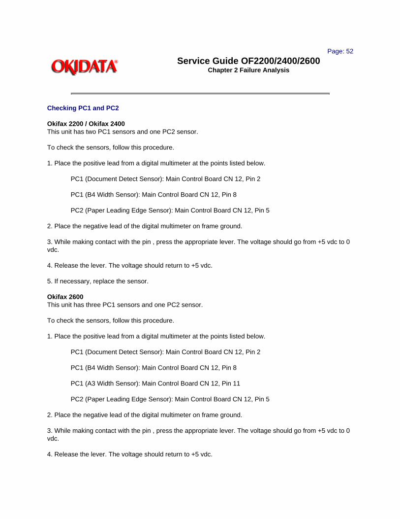
Checking PC1 and PC2
Okifax 2200 / Okifax 2400This unit has two PC1 sensors and one PC2 sensor.
To check the sensors, follow this procedure.
1. Place the positive lead from a digital multimeter at the points listed below.
PC1 (Document Detect Sensor): Main Control Board CN 12, Pin 2
PC1 (B4 Width Sensor): Main Control Board CN 12, Pin 8
PC2 (Paper Leading Edge Sensor): Main Control Board CN 12, Pin 5
2. Place the negative lead of the digital multimeter on frame ground.
3. While making contact with the pin , press the appropriate lever. The voltage should go from +5 vdc to 0 vdc.
4. Release the lever. The voltage should return to +5 vdc.
5. If necessary, replace the sensor.
Okifax 2600This unit has three PC1 sensors and one PC2 sensor.
To check the sensors, follow this procedure.
1. Place the positive lead from a digital multimeter at the points listed below.
PC1 (Document Detect Sensor): Main Control Board CN 12, Pin 2
PC1 (B4 Width Sensor): Main Control Board CN 12, Pin 8
PC1 (A3 Width Sensor): Main Control Board CN 12, Pin 11
PC2 (Paper Leading Edge Sensor): Main Control Board CN 12, Pin 5
2. Place the negative lead of the digital multimeter on frame ground.
3. While making contact with the pin , press the appropriate lever. The voltage should go from +5 vdc to 0 vdc.
4. Release the lever. The voltage should return to +5 vdc.

5. If necessary, replace the sensor.
Copyright 1997, Okidata, Division of OKI America, Inc. All rights reserved. See the OKIDATA Business Partner Exchange (BPX) for any updates to this material. (http://bpx.okidata.com)

Page: 53
Service Guide OF2200/2400/2600Chapter 2 Failure Analysis
RAP 05 Auto Dial Problem
Make sure that the selected dialing method (tone/pulse) is appropriate for the TELCO / PBX needs. Refer to the Dialing Parameters in the Users Documentation.
START
Does the manual dial function properly?
NO Can a dial tone be heard when the handset is picked up?
NO Check the line cable and the exchange.
YES Check for closed network, method of dialing, dial rate.
YES Replace the problem unit with a known " good" unit. Does the "good" unit dial?
NO Go to LOCATION PROBLEM.
YES Does "DIALING" appear on the LCD display?
YES End of procedure.
NO Does "TELEPHONE BUSY" appear on the LCD display?
NO End of procedure.
YES Hang up the external telephone set.
Has the problem been resolved?
YES End of procedure.
NO Replace the following.
Network control board
Main control board
LOCATION PROBLEM
Check the following.
One Touch and Auto Dial parameters
OFF-Hook Bypass

Has the problem been resolved?
YES End of procedure.
NO Contact Technical Support.
Copyright 1997, Okidata, Division of OKI America, Inc. All rights reserved. See the OKIDATA Business Partner Exchange (BPX) for any updates to this material. (http://bpx.okidata.com)

Page: 54
Service Guide OF2200/2400/2600Chapter 2 Failure Analysis
RAP 06 Data Transmission Problem
This section explains how to localize the cause of problems occurring after completion of connection with a remote station.
START
Adjust send signal power level.
Okifax 2200: Technical Function 21
Okifax 2400/2600: Technical Function 57
Has the problem been resolved?
YES End of procedure.
NO Set SHORTEN PROTOCOL to OFF.
Okifax 2200: Technical Function 08
Okifax 2400/2600: Technical Function 76
Has the problem been resolved?
YES End of procedure.
NO Set CCITT ECM to OFF.
Okifax 2200: Technical Function 30
Okifax 2400/2600: Technical Function 77
Has the problem been resolved?
YES End of procedure.
NO Set IGNORE 1ST DIS to ON.
Okifax 2200: Technical Function 14
Okifax 2400/2600: Technical Function 78
Has the problem been resolved?
YES End of procedure.

NO Set PROTECTIVE TONE to ON (for international calling)
Okifax 2200: Technical Function 16
Okifax 2400/2600: Technical Function 80
Has the problem been resolved?
YES End of procedure.
NO Set MH ONLY to ON.
Okifax 2200: Technical Function 07
Okifax 2400/2600: Technical Function 75
Has the problem been resolved?
YES End of procedure.
NO Change the HIGH-SPEED MODEM RATE as follows.
Okifax 2200: 4800 bps - Technical Function 13
Okifax 2400/2600: 9600 bps - Technical Function 86
Has the problem been resolved?
YES End of procedure.
NO Replace the problem unit with a known "good" unit. Follow the preceding steps.
Does the replaced fax unit transmit normally?
NO Check the line and the network of the problem fax.
YES Replace the main control board of the problem fax.
Has the problem been resolved?
YES End of procedure.
NO Replace the NCU board.
Copyright 1997, Okidata, Division of OKI America, Inc. All rights reserved. See the OKIDATA Business Partner Exchange (BPX) for any updates to this material. (http://bpx.okidata.com)

Page: 55
Service Guide OF2200/2400/2600Chapter 2 Failure Analysis
RAP 07 Auto Reception Problem
START
Is the manual reception OK?
NO Does the handset /telephone ring when a call arrives?
NO Perform the following
Check the handset/telephone set, the line, and the exchange.
YES Answer the call. Then, check the following items.
Is the unit placed in the manual receive mode?
Was the START key pressed to answer the call?
Is the closed network ON? Is the remote phone number registered in one touch keys or three-digit auto dial codes?
YES Is machine in the auto receive mode? If not, place the unit in auto receive mode by pressing AUTO REC key.
Has the problem been resolved?
YES End of procedure.
NO Set CLOSED NETWORK to OFF.
Okifax 2200: User Function 08
Okifax 2400/2600: User Function 21
Has the problem been resolved?
YES End of procedure.
NO Is the ringing signal detected at Pin 9 of CN7 of the network control unit board?
YES Replace the main control board.
NO Replace network control unit board.
Has the problem been resolved?

YES End of procedure.
NO Replace the line board.
Has the problem been resolved?
YES End of procedure.
NO Contact Technical Support.
Copyright 1997, Okidata, Division of OKI America, Inc. All rights reserved. See the OKIDATA Business Partner Exchange (BPX) for any updates to this material. (http://bpx.okidata.com)

Page: 56
Service Guide OF2200/2400/2600Chapter 2 Failure Analysis
RAP 08 Reception Problem
This section explains how to localize the cause of problems occurring after completion of connection with a remote station.
START
Adjust the equalizing level.
Okifax 2200: Technical Function 22
Okifax 2400/2600: Technical Function 60
Has the problem been resolved?
YES End of procedure.
NO Set CED-DIS INTERVAL to 1.5 seconds.
Okifax 2200: Technical Function 15
Okifax 2400/2600: Technical Function 79
Has the problem been resolved?
YES End of procedure.
NO Set SHORTEN PROTOCOL to OFF.
Okifax 2200: Technical Function 08
Okifax 2400/2600: Technical Function 76
Has the problem been resolved?
YES End of procedure.
NO Set CCITT ECM to OFF.
Okifax 2200: Technical Function 30
Okifax 2400/2600: Technical Function 77
Has the problem been resolved?
YES End of procedure.

NO Set MH ONLY to ON.
Okifax 2200: Technical Function 07
Okifax 2400/2600: Technical Function 75
Has the problem been resolved?
YES End of procedure.
NO Change the HIGH-SPEED MODEM RATE as follows.
Okifax 2200: 4800 bps - Technical Function 13
Okifax 2400/2600: 9600 bps - Technical Function 86
Replace the problem unit with a known "good" unit. Then repeat the preceding procedures.
Does the replaced unit receive normally?
NO Check the line and the network of the problem unit.
YES Replace the main control board of the problem unit.
Copyright 1997, Okidata, Division of OKI America, Inc. All rights reserved. See the OKIDATA Business Partner Exchange (BPX) for any updates to this material. (http://bpx.okidata.com)

Page: 57
Service Guide OF2200/2400/2600Chapter 2 Failure Analysis
RAP 09 Scan Operation Test Failure
NOTE:Set SENSOR CALIBRATION to ON.
Okifax 2200: Technical Function 25
Okifax 2400/2600: Technical Function 84
START
Perform the Sensor Calibration Adjustment.
Does "SCANNING ERROR" appear on LCD while adjusting?
YES Check that white plain bond paper of correct size is loaded on the feeder.
Okifax 2200: B4 size
Okifax 2400: B4 size
Okifax 2600: A3 size
Disconnect the cable from connector CN4 on the printer control board and leave the other end connected to CN2 on the power supply board. Voltage measurements should be taken from this cable. Check -12 vdc at Pin 9. If -12 vdc is not present, replace the power supply board.
Has the problem been resolved?
YES End of procedure.
NO Replace the following in the order listed.
1. Printer Control Board
2. Contact Image Sensor Assembly
3. Main Control Board
NO Are there document feeding problems during the scanning check?
YES Refer to the appropriate RAP, depending on the type of abnormal feed.
NO End of procedure.
Copyright 1997, Okidata, Division of OKI America, Inc. All rights reserved. See the OKIDATA Business

Partner Exchange (BPX) for any updates to this material. (http://bpx.okidata.com)

Page: 58
Service Guide OF2200/2400/2600Chapter 2 Failure Analysis
RAP 10 LED Test Failure
START
Perform the LED TEST.
Do all of the listed LEDs light?
Okifax 2200
ALARM > PHOTO >DARK > NORMAL> LIGHT> AUTO REC
Okifax 2400/2600
ALARM > PHOTO > EX.FINE > FINE > STD> LIGHT> NORMAL> DARK >AUTO REC
YES End of procedure.
NO Replace the operator panel board.
Has the problem been resolved?
YES End of procedure.
NO Check the connection cable between the main control board and the operator panel unit.
Has the problem been resolved?
YES End of procedure.
NO Replace the main control board.
End of procedure.
Copyright 1997, Okidata, Division of OKI America, Inc. All rights reserved. See the OKIDATA Business Partner Exchange (BPX) for any updates to this material. (http://bpx.okidata.com)

Page: 59
Service Guide OF2200/2400/2600Chapter 2 Failure Analysis
RAP 11 Tone Send Test Failure
START
Is the Line Monitor Volume adjusted so the tone will be audible?
Okifax 2200: Technical Function 05
Okifax 2400/2600: Technical Function 10
NO Modify the appropriate Technical Function.
YES Is CN3 (Speaker Harness) connected to CN3 of the main control board?
YES Replace the main control board.
NO Connect the cable.
End of procedure.
Copyright 1997, Okidata, Division of OKI America, Inc. All rights reserved. See the OKIDATA Business Partner Exchange (BPX) for any updates to this material. (http://bpx.okidata.com)

Page: 60
Service Guide OF2200/2400/2600Chapter 2 Failure Analysis
RAP 12 High Speed Modem Test Failure
START
Perform the High Speed Modem Send Test for the transmitter.
Perform the High Speed Modem Receive Test for the receiver.
If you are in RX mode, go to A. If you are in the TX mode, continue here.
Does the modem signal (.14 vac) appear at Pin 1 and 4 of CN7 (network control board)?
YES Replace network control board.
Has the problem been resolved?
YES End of procedure.
NO Replace the main control board.
NO Check for +12 vdc and -12 vdc on the main control board.
+ 12 vdc present at CN5 Pin 14. - 12 vdc present at CN5 Pin 15
Do +12 vdc and -12 vdc appear at these points?
NO Disconnect the cable from CN4 of the printer control board and measure the voltage at pin 14 and 15 of the disconnected cable.If +/-12 vdc are not present, replace the power supply board.
YES Replace the main control board.
ADoes the receive signal (.9 vac) appear between L1 and L2 on the line-JU board?
NO Check the line.
YES Does the receive signal (.12 vac) appear between CN7-2 (R) and CN7-1 (GND) of network control board?
YES Replace the main control board.
NO Is +12 vdc present at CN7- Pin 14 and -12 vdc present at CN7- Pin 15 of the network control board?
YES Replace the network control board.

Has the problem been resolved?
YES End of procedure.
NO Replace the line board.
Has the problem been resolved?
YES End of procedure.
NO Checking CN5 on the main control board, is -12 vdc present at Pin 14 and +12 vdc present at Pin 15?
YES Check the route of these voltages (cable between the network control board and the main control board).
NO Disconnect the cable from CN4 of the printer control board and measure the voltage at pin 14 and 15 of the connecting cable. If +/-12 vdc are not present, replace the power supply board.
Check the cables and the route of these voltages (main control, network control, and printer control boards).
Has the problem been resolved?
YES End of procedure.
NO Replace the main control board.
End of procedure.
Copyright 1997, Okidata, Division of OKI America, Inc. All rights reserved. See the OKIDATA Business Partner Exchange (BPX) for any updates to this material. (http://bpx.okidata.com)

Page: 61
Service Guide OF2200/2400/2600Chapter 2 Failure Analysis
RAP 13 Multi-frequency Send Test Failure
START
Detach the phone line from the unit.
Remove the right side and rear covers.
Set up an oscilloscope as listed below.
Set the time / div to .5 ms / division. Set Channel 1 volts / div to .1 volt / division.
Perform MF Send Test.
Place the oscilloscope probe on pin 1 of CN3 on the main control board.
Is a .15 v analog signal present?
YES Replace the speaker.
NO Replace the main control board.
Is the problem resolved?
YES End of procedure.
NO Replace the operator panel assembly.
Is the problem resolved?
YES End of procedure.
NO Contact Okidata Technical Support.
Copyright 1997, Okidata, Division of OKI America, Inc. All rights reserved. See the OKIDATA Business Partner Exchange (BPX) for any updates to this material. (http://bpx.okidata.com)

Page: 62
Service Guide OF2200/2400/2600Chapter 2 Failure Analysis
RAP 14 Voice Message Test Failure
START
Perform the Voice Message Test.
Has the Monitor Volume been set to LOW or HIGH?
Okifax 2200: User Function 05
Okifax 2400/2600: Technical Function 10
NO Set Monitor Volume to LOW or HIGH.
YES Replace the main control board.
Has the problem been resolved?
YES End of procedure.
NO Replace the speaker.
Copyright 1997, Okidata, Division of OKI America, Inc. All rights reserved. See the OKIDATA Business Partner Exchange (BPX) for any updates to this material. (http://bpx.okidata.com)

Page: 63
Service Guide OF2200/2400/2600Chapter 2 Failure Analysis
RAP 15 No Acoustic Line Monitor
There are two source routes of the acoustic line monitor.
General communication signal
DP pulse signal
START
Has the Monitor Volume been set to LOW or HIGH?
Okifax 2200: User Function 05
Okifax 2400/2600: Technical Function 10
NO Set Monitor Volume to LOW or HIGH.
YES Replace the main control board.
Has the problem been resolved?
YES End of procedure.
NO Replace the speaker.
Copyright 1997, Okidata, Division of OKI America, Inc. All rights reserved. See the OKIDATA Business Partner Exchange (BPX) for any updates to this material. (http://bpx.okidata.com)

Page: 64
Service Guide OF2200/2400/2600Chapter 2 Failure Analysis
RAP 16 Document Does Not Feed
START
Place document(s) on the ADF tray.
Does the ADF roller rotate?
NO Check that the scan motor is properly connected to CN8 of the printer control board.
Is the problem resolved?
YES End of procedure.
NO Does PC1 function properly?. (Refer to RAP 04)
NO Replace PC1
YES Replace the following in the listed order.
1. Printer Control Board
2. Scan Motor
YES Is the control panel unit properly closed?
NO Properly close the control panel unit.
YES Is the leading edge of document curled or folded?
YES Load a document that is not curled or folded.
NO Verify that there are not too many documents loaded. Verify that the paper thickness does not exceed 0.15 mm.
Do the documents meet the above criteria?
NO Use documents that meet the above criteria.
YES Are the paper paths of the scanning route blocked?
YES Clear the scanning route.
NO Replace the following in the order listed.
(1) ADF Roller, (2) Sub-Roller, (3) Separation Rubber

Copyright 1997, Okidata, Division of OKI America, Inc. All rights reserved. See the OKIDATA Business Partner Exchange (BPX) for any updates to this material. (http://bpx.okidata.com)

Page: 65
Service Guide OF2200/2400/2600Chapter 2 Failure Analysis
RAP 17 Multiple Document Feeds
START
Are the leading edges of the documents aligned?
NO Align them.
YES Is the separation rubber dirty?
YES Clean it with water.
NO Does the separation rubber assembly return to its original position when pushed?
NO Check the ADF spring, the tension arm, and the back-up plate.
YES Replace the separation rubber.
Has the problem been resolved?
YES End of procedure.
NO Clean the ADF roller assembly.
End of procedure.
Copyright 1997, Okidata, Division of OKI America, Inc. All rights reserved. See the OKIDATA Business Partner Exchange (BPX) for any updates to this material. (http://bpx.okidata.com)

Page: 66
Service Guide OF2200/2400/2600Chapter 2 Failure Analysis
RAP 18 Document Skews
START
Are the document guides set to meet the document width? Are the documents properly loaded along the guides?
NO Set the guides to meet the document width. Load the documents properly along the guides.
YES Are all of the documents the same width?
NO Load ONLY documents of the same width.
YES Check the thickness of the document(s). Is the thickness within specifications?
Multiple documents: 0.06 to 0.13 mm
Single documents: 0.05 to 0.15 mm
NO Use documents of the proper specification.
YES Are the documents normal?
NO Use a carrier sheet.
YES Check for the following:
Adhesive (paste, tape) on the surface of the documents.
The leading edge(s) of the document(s) are uneven.
Is the control panel unit closed firmly?
NO Close the control panel unit firmly.
YES Is the paper path obstructed?
YES Remove the obstructions.
NO Is the separation rubber dirty?
YES Clean it with water.
NO Press on the pinch rollers. When released, do they return to their normal positions?

NO Set them properly.
YES Are the feed rollers dirty?
YES Clean them.
NO Are the feed rollers worn or slippery?
YES Replace them.
NO Go to the next step.
Is the ADF roller or the sub-roller dirty?
YES Clean them.
NO Replace the following in the listed order
ADF Roller
Sub-Roller
Feed Rollers
Pinch Rollers
End of procedure.
Copyright 1997, Okidata, Division of OKI America, Inc. All rights reserved. See the OKIDATA Business Partner Exchange (BPX) for any updates to this material. (http://bpx.okidata.com)

Page: 67
Service Guide OF2200/2400/2600Chapter 2 Failure Analysis
RAP 19 Document Jams
START
Load a document.
Does the document feed?
NO Perform each of the following until the problem is resolved.
1. Check PC1. Refer to RAP 04.
2. Replace main control board.
3. Verify correct power supply voltages.
4. Replace the gear frame assembly.
YES Does the unit feed the document about 7 cm, then stop with SELECT LOCATION displayed on the LCD?
NO Perform each of the following until the problem is resolved.
1. Check PC2. Refer to RAP 04.
2. Replace main control board.
YES Press COPY.
Document has jammed.
Are the documents abnormal?
YES Check for the following:
1. Adhesive (paste, tape) on the surface of the documents.
2. Abnormal thickness (less than 0.06 mm).
3. Uneven leading edge(s).
4. Length too great (longer than 500 mm).
5. Obstacles in the document path.

Corrective Actions
For 1, clean surface and photocopy the document. Use the copy for faxing.
For 2, use documents of the specified thickness and photocopy the document. Use the copy for faxing.
For 3, cut the leading edge(s) to make them even.
For 4, use document within length specified.
For 5, clear obstacles from the document path.
NO Is the paper path blocked?
YES Clear the paper path.
NO Are the parts in the paper path worn or damaged?
YES Replace them.
NO Are the feed rollers dirty?
YES Clean them.
NO Replace the feed roller(s).
End of procedure.
Copyright 1997, Okidata, Division of OKI America, Inc. All rights reserved. See the OKIDATA Business Partner Exchange (BPX) for any updates to this material. (http://bpx.okidata.com)

Page: 68
Service Guide OF2200/2400/2600Chapter 2 Failure Analysis
RAP 20 Problems Shown On LCD Display
NOTE:The Action Items referred to in RAP 20A through RAP 20G are listed at the end of the LCD Problem Charts.
Category LCD Message Display Trouble Trouble-shooting Flowchart Number
Cover Open COVER OPEN [FAX] CLOSE COVER
The cover (copy stacker) is open.
20A
Printer Interface Error
PRINTER ALARM 1 [TEL] CONFIRM AND "STOP"
Error in the interface between the fax unit and the printer unit.
20B
Engine Errors
PRINTER ALARM 2 [TEL] CONFIRM AND "STOP"
Engine controller error (ROM/RAM error)
20C
^ PRINTER ALARM 3 [TEL] CONFIRM AND "STOP"
Fan motor rotation error
20D
^ PRINTER ALARM 4 [TEL] CONFIRM AND "STOP"
Fuser unit thermal error
20E
Recording Paper/Jam Error
PAPER JAM [TEL] CONFIRM AND STOP
Recording paper feed jam transport jam ejection jam recording size error
20F
Paper Cassette Request
NO PAPER [TEL] REPLACE PAPER
No recording paper cassette or no recording paper.
20G
Daily Status
01/31/93 23:59 [T/F] WAIT A MOMENT
The printer is warming up.
N/A
^ NO TONER [FAX] REPLACE TONER CART.
Toner is running out.
N/A
Copyright 1997, Okidata, Division of OKI America, Inc. All rights reserved. See the OKIDATA Business Partner Exchange (BPX) for any updates to this material. (http://bpx.okidata.com)

Page: 69
Service Guide OF2200/2400/2600Chapter 2 Failure Analysis
RAP 20A Cover Open
START
"COVER OPEN" appears on the LCD display.
Close the cover (copy stacker).
Has the problem been resolved?
YES End of procedure.
NO Has the fan motor stopped?
YES Is the cover open switch connector out of position?
YES Connect the cover open switch connector.
NO Refer to Action Item 2.
NO Check the power supply at CN4, Pins 1, 2, and 3 for +38 vdc. Refer to Appendix A.
If not present, replace the power supply.
End of procedure.
Copyright 1997, Okidata, Division of OKI America, Inc. All rights reserved. See the OKIDATA Business Partner Exchange (BPX) for any updates to this material. (http://bpx.okidata.com)

Page: 70
Service Guide OF2200/2400/2600Chapter 2 Failure Analysis
RAP 20B Printer Alarm 1
START
"PRINTER ALARM 1" appears on LCD display.
Power OFF the unit, the power ON.
Does "PRINTER ALARM 1" remain on display?
NO Refer to Action Item 3.
YES Are the connections of the interface cable between the main control board (CN11) and the printer control board (CN10) correctly made?
NO Correctly make the connections.
YES Refer to Action Item 4.
End of procedure.
Copyright 1997, Okidata, Division of OKI America, Inc. All rights reserved. See the OKIDATA Business Partner Exchange (BPX) for any updates to this material. (http://bpx.okidata.com)

Page: 71
Service Guide OF2200/2400/2600Chapter 2 Failure Analysis
RAP 20C Printer Alarm 2
START
"PRINTER ALARM 2" appears on the LCD display.
Power OFF the unit, then power ON.
Does "PRINTER ALARM 2" remain on the LCD display?
NO Refer to Action Item 5.
YES Refer to Action Item 6.
Copyright 1997, Okidata, Division of OKI America, Inc. All rights reserved. See the OKIDATA Business Partner Exchange (BPX) for any updates to this material. (http://bpx.okidata.com)

Page: 72
Service Guide OF2200/2400/2600Chapter 2 Failure Analysis
RAP 20D Printer Alarm 3
START
"PRINTER ALARM 3" appears on the LCD display.
Open the cover, then close the cover.
Has the fan motor stopped?
NO Refer to Action Item 7 .
YES Is the fan motor connector properly connected to the printer control board?
NO Connect the fan motor connector properly.
YES Refer to Action Item 8 .
Copyright 1997, Okidata, Division of OKI America, Inc. All rights reserved. See the OKIDATA Business Partner Exchange (BPX) for any updates to this material. (http://bpx.okidata.com)

Page: 73
Service Guide OF2200/2400/2600Chapter 2 Failure Analysis
RAP 20E Printer Alarm 4
START
"PRINTER ALARM 4" appears on the LCD display.
Power OFF, then power ON.
After a short delay, does "PRINTER ALARM 4" appear on the LCD display?
YES Remove the fuser assembly for testing (Refer to the Action Items Diagram). Check the resistance between the thermistor contacts. At room temperature, it should read approximately 200 Kohms.
Is the resistance correct?
NO Replace the fusing unit.
YES Does the thermistor contact correctly touch the contact assembly when the fusing unit is installed? (Refer to the Action Items Diagram)
NO Adjust the contacts as necessary.
YES Refer to Action Item 9.
Replace the printer control board.
NO Does PRINTER ALARM 4 occur approximately 60 seconds after powering ON the unit?
YES Is the heater lamp of the fusing unit ON? To check, remove the stacker cover. Overide the cover interlock. Light can be seen from the ends of the fuser when the heater lamp is ON.
NO Is the heater or thermistor open? Measure the resistance between the two heater contacts. Normal resistance is approximately 0 ohms.
YES Replace the fusing unit.
NO Is the AC voltage from the fuser present at the contact assembly?
NO Replace the printer control board. If the problem persists, replace the power supply board.
YES Replace the fusing unit.
NO Refer to Action Item 9.

Copyright 1997, Okidata, Division of OKI America, Inc. All rights reserved. See the OKIDATA Business Partner Exchange (BPX) for any updates to this material. (http://bpx.okidata.com)

Page: 74
Service Guide OF2200/2400/2600Chapter 2 Failure Analysis
RAP 20F Paper Jam
START
"REMOVE THE PAPER AND PRESS STOP" appears on the LCD.
Is the paper cassette loaded properly?
NO Load it properly.
YES Is the paper of the correct specified size? Check both the first and second (optional) tray paper sizes.
NO Replace with paper of the correct specified size
or
Reprogram correct size for appropriate cassette.
YES Does the same error occur frequently?
NO Remove the jammed paper.
YES Does the error occur while paper is in the paper cassette?
YES Refer to Action Item 10.
NO Does the error occur while the paper is under the image drum?
YES Refer to Action Item 11.
NO Does the error occur while the paper is being ejected?
YES Refer to Action Item 12.
NO Refer to Action Item 13.
End of procedure.
Copyright 1997, Okidata, Division of OKI America, Inc. All rights reserved. See the OKIDATA Business Partner Exchange (BPX) for any updates to this material. (http://bpx.okidata.com)

Page: 75
Service Guide OF2200/2400/2600Chapter 2 Failure Analysis
RAP 20G No Paper Cassette
START
"NO PAPER REPLACE PAPER" appears on the LCD display.
Has the paper cassette been loaded?
YES Load recording paper.
NO Refer to Action Item 14. .
Copyright 1997, Okidata, Division of OKI America, Inc. All rights reserved. See the OKIDATA Business Partner Exchange (BPX) for any updates to this material. (http://bpx.okidata.com)

Page: 76
Service Guide OF2200/2400/2600Chapter 2 Failure Analysis
Action Items for LCD Display Problems
Number Action 1 Replace printer control board. If the problem persists, replace power supply board.
2 Check power supply voltages, cover open switch, and cover open switch arm. Replace printer control board.
3 Check installation of the main control board, connection of connector CN11.
4 Try the following:
1. Check power supply voltages.2. Replace printer board. 3. Replace main control board.
5 Check installation of printer control board, power supply board.
6 Replace printer control board.
7 Check fan motor, printer control board connectors, power supply voltages.
8 Replace fan motor, printer control board, power supply board.
9 Check electrical connection between power supply board and the contact assembly.
10 Check entrance sensor lever, hopping roller, resist motor, power supply board, cover open switch actuator.
11 Check image drum, cover open switch actuator, drum motor, drum motor gear, printer control board.
12 Check exit sensor lever, cover open switch actuator, power supply board.
13 Replace printer control board, main control board, power supply board.
14 Check paper sensor lever, power supply board, printer control board, main control board.
Action Items DiagramHigh voltage outputs (and measurement points) are connected to the contact assembly as shown in the diagram below.

Copyright 1997, Okidata, Division of OKI America, Inc. All rights reserved. See the OKIDATA Business Partner Exchange (BPX) for any updates to this material. (http://bpx.okidata.com)
Page: 77
Service Guide OF2200/2400/2600Chapter 2 Failure Analysis
RAP 21 Image Problems
NOTE:It is recommended that the image drum area and the contact assembly are kept clean.
Index to Image Problems
Symptom Reference Figure Flowchart Number Poor Print Quality (images are Figure A 21Alight or blurred as a whole)
Dark Background Density Figure B 21B
Blank Output Figure C 21C
Vertical Black Stripes Figure D 21D
Repetitive Marks Figure E 21E
Vertical White Stripes Figure F 21F
Areas Missing N/A 21G
Poor Fusing (image smears when touched) N/A 21H
Sample Outputs

Copyright 1997, Okidata, Division of OKI America, Inc. All rights reserved. See the OKIDATA Business Partner Exchange (BPX) for any updates to this material. (http://bpx.okidata.com)

Page: 78
Service Guide OF2200/2400/2600Chapter 2 Failure Analysis
RAP 21A Poor Print Quality (Images Light or Blurred as a Whole)
NOTE:If the output is of poor print quality upon receiving a fax, make a local copy before assuming that the unit is defective. It is possible that the transmitting facsimile is defective.
START
Is the TONER LOW message displayed?
YES Add toner.
NO Is the paper used designed for xerographic printing?
NO Use xerographic paper.
YES Is the LED head dirty?
YES Clean it.
NO Are the LED head and cable properly connected? Check the LED head connector and connector CN3 of the printer control board for proper connection.
YES End of procedure.
NO Properly connect the LED head and cable.
NO Are the contacts of the transfer roller clean and properly touching the high-voltage contact assembly?
NO Clean / Replace the high-voltage contact assembly.
YES Replace the transfer roller.
Has the problem been resolved?
YES End of procedure
NO Replace the image drum cartridge.
Has the problem been resolved?
YES End of procedure.

NO Replace the power supply board.
Has the problem been resolved?
YES End of procedure.
NO Replace the printer control board.
Copyright 1997, Okidata, Division of OKI America, Inc. All rights reserved. See the OKIDATA Business Partner Exchange (BPX) for any updates to this material. (http://bpx.okidata.com)

Page: 79
Service Guide OF2200/2400/2600Chapter 2 Failure Analysis
RAP 21B Dark Background Density
NOTE:If a received fax has a dark background, make a local copy before assuming that the unit is defective. It is possible that the transmitting facsimile is defective.
START
Has the image drum been exposed to external light?
YES Place the image drum cartridge into the unit and wait about 30 minutes before testing or replacing image drum.
NO Is the fuser roller of the fusing unit dirty?
YES Clean the roller.
NO Is the cleaning roller contact (of the image drum) clean and properly touching the high-voltage contact assembly?
NO Clean / Replace the high-voltage contact assembly.
YES Replace the image drum cartridge.
Has the problem been resolved?
YES End of procedure.
NO Verify LED Head Timing Adjustment and correct if necessary.
Has the problem been resolved?
YES End of procedure.
NO Replace the power supply board.
Has the problem been resolved?
YES End of procedure.
NO Replace the printer control board.
Copyright 1997, Okidata, Division of OKI America, Inc. All rights reserved. See the OKIDATA Business Partner Exchange (BPX) for any updates to this material. (http://bpx.okidata.com)

Page: 80
Service Guide OF2200/2400/2600Chapter 2 Failure Analysis
RAP 21C Printed Output is Blank
NOTE:If a fax is received, and the output has black vertical stripes, make a local copy before assuming that the unit is defective. It is possible that the transmitting facsimile is defective.
STARTIs the LED head correctly connected? Check the LED Head connector and connector CN3 on the printer control board.
NO Connect the LED head.
YES Is the image drum cartridge touching the ground contact on the high-voltage contact assembly?
NO Clean / Replace the high-voltage contact assembly and clean the image drum contacts.
YES Replace the LED head.
Has the problem been resolved?
YES End of procedure.
NO Replace the printer control board.
Has the problem been resolved?
YES End of procedure.
NO Replace the power supply board.
Has the problem been resolved?
YES End of procedure.
NO Replace the main control board.
Copyright 1997, Okidata, Division of OKI America, Inc. All rights reserved. See the OKIDATA Business Partner Exchange (BPX) for any updates to this material. (http://bpx.okidata.com)

Page: 81
Service Guide OF2200/2400/2600Chapter 2 Failure Analysis
RAP 21D Vertical Black Stripes on Printed Output
NOTE:If a fax is received, and the output has black vertical stripes, make a local copy before assuming that the unit is defective. It is possible that the transmitting facsimile is defective.
START
Is the TONER LOW message displayed?
YES Add toner.
NO Replace the image drum cartridge.
Has the problem been resolved?
YES End of procedure.
NO Replace the LED head.
Has the problem been resolved?
YES End of procedure.
NO Replace the printer control board.
Has the problem been resolved?
YES End of procedure.
NO Replace the power supply board.
Copyright 1997, Okidata, Division of OKI America, Inc. All rights reserved. See the OKIDATA Business Partner Exchange (BPX) for any updates to this material. (http://bpx.okidata.com)

Page: 82
Service Guide OF2200/2400/2600Chapter 2 Failure Analysis
RAP 21E Repetitive Spaced Marks on Printed Output
NOTE:If a fax is received, and the output has repetitive spaced marks a local copy before assuming that the unit is defective. It is possible that the transmitting facsimile is defective. STARTMeasure the distance between marks to identify the problem
Distance Between Marks
Problem Corrective Action
1.66 inches 42.2 mm Developing roller inside image drum cartridge
Replace or clean the image drum cartridge.
3.71 inches 94.2 mm Image drum in image drum cartridge
Replace the image drum cartridge.
2.27 inches 58 mm Rollers in image drum cartridge
Replace the image drum cartridge.
1.56 inches 40 mm ^ Replace the image drum cartridge.
1.24 inches 31.5 mm ^ Replace the image drum cartridge.
2.01 inches 51 mm Transfer roller Replace the transfer roller.
2.47 inches 63 mm Heater roller inside fusing unit
Replace the fusing unit assembly.
2.23 inches 57 mm Pressure roller Replace the pressure roller.
2.72 inches Pressure roller Replace the pressure roller.
Copyright 1997, Okidata, Division of OKI America, Inc. All rights reserved. See the OKIDATA Business Partner Exchange (BPX) for any updates to this material. (http://bpx.okidata.com)

Page: 83
Service Guide OF2200/2400/2600Chapter 2 Failure Analysis
RAP 21F Vertical White Streaks on Printed Output
NOTE:If a fax is received, and the output has vertical white streaks, make a local copy before assuming that the unit is defective. It is possible that the transmitting facsimile is defective.
START
Is the LED head dirty?
YES Clean the LED head.
NO Is the contact of the transfer roller clean and properly touching the high-voltage contact assembly?
NO Clean / Replace the high-voltage contact assembly.
YES Replace the transfer roller.
Has the problem been resolved?
YES End of procedure.
NO Is the LED head properly installed? Check the LED Head connector and connector CN3 on the printer control board
NO Install the LED head properly.
YES Replace the image drum cartridge.
Has the problem been resolved?
YES End of procedure.
NO Replace the LED head.
Has the problem been resolved?
YES End of procedure.
NO Replace the printer control board.
Copyright 1997, Okidata, Division of OKI America, Inc. All rights reserved. See the OKIDATA Business Partner Exchange (BPX) for any updates to this material. (http://bpx.okidata.com)

Page: 84
Service Guide OF2200/2400/2600Chapter 2 Failure Analysis
RAP 21G Areas Missing From Printed Output
NOTE:If a fax is received, and the output has missing print, make a local copy before assuming that the unit is defective. It is possible that the transmitting facsimile is defective.
START
Check to see if there is a sufficient amount of toner in the image drum cartridge. If not, replace the toner cartridge.
Are the contacts of the transfer roller, developing roller, image drum, and charging roller clean and properly touching the contact assembly?
NO Clean / Replace the high-voltage contact assembly.
YES Replace the image drum cartridge.
Has the problem been resolved?
YES End of procedure.
NO Is the LED head installed properly? Check the LED Head connector and connector CN3 on the printer control board.
NO Properly install the LED head.
YES Replace the LED head.
Has the problem been resolved?
YES End of procedure.
NO Replace the printer control board.
Has the problem been resolved?
YES End of procedure.
NO Replace the power supply board.
Has the problem been resolved?
YES End of procedure.
NO Replace the main control board.

Copyright 1997, Okidata, Division of OKI America, Inc. All rights reserved. See the OKIDATA Business Partner Exchange (BPX) for any updates to this material. (http://bpx.okidata.com)

Page: 85
Service Guide OF2200/2400/2600Chapter 2 Failure Analysis
RAP 21H Poor FusingNOTE:
If the fusing unit is not functioning, the message PRINTER ALARM 4 will be displayed on the LCD. Refer to RAP 20E.
Use RAP 21H when printed output smears when touched.
STARTIs the paper used designed for use in xerographic printers?NO Use paper designed for use in xerographic paper.YES Are the springs for the pressure roller functioning properly? Do they compress when pushed?
NO Replace the springs.YES Replace the printer control board.
Has the problem been resolved?YES End of procedure.
NO Replace the power supply board.Has the problem been resolved?
YES End of procedure.NO Replace the fuser assembly.
Copyright 1997, Okidata, Division of OKI America, Inc. All rights reserved. See the OKIDATA Business Partner Exchange (BPX) for any updates to this material. (http://bpx.okidata.com)

Page: 86
Service Guide OF2200/2400/2600Chapter 2 Failure Analysis
2.6 TESTS
General Information
NOTE:Before running the tests, the unit MUST be in the idle mode.
The operator or service technician can perform the following tests by using the numeric key pad.
1. Self-Diagnosis
2. Scan Operation / CIS Calibration
3. LED Test
4. Tone Send Test
5. High-Speed Modem Transmission Test
6. High-Speed Modem Reception Test
7. Multi-Frequency Send Test
8. Print Test
9. Voice Message Test
Copyright 1997, Okidata, Division of OKI America, Inc. All rights reserved. See the OKIDATA Business Partner Exchange (BPX) for any updates to this material. (http://bpx.okidata.com)
Page: 87
Service Guide OF2200/2400/2600Chapter 2 Failure Analysis
2.6.01 Self-Diagnosis
General InformationThe Self-Diagnosis verifies operation of the printer unit, and confirms the presence of Random Access Memory (RAM) and Read-Only Memory (ROM). The ROM Version is also printed.
Procedure
1. Press SELECT FUNCTION.
2. Press COPY twice.
3. Press LEFT ARROW three times.
After approximately __________ seconds, the test results will be printed.
Okifax 2200: 2.5 minutes
Okifax 2400/2600: 90 seconds
4. Press SELECT FUNCTION to exit the test.
Interpret the report (refer to the sample) as follows.
1. Pattern 1 - All White Image for 64 lines
2. Pattern 2 - Alternating Black/White Image (64 columns by 64 lines)
3. Pattern 3 - All Black Image for 64 lines
4. Pattern 4 - Gray Image for 128 lines
5. Pattern 5 - All White Image for 64 lines
6. M-ROM Version (Main Controller)
7. M-ROM Check (Main Controller)
8. M-RAM Check (Main Controller)
9. P-ROM Version (Printer Controller)
10. P-ROM Check (Printer Controller)
11. P-RAM Check (Printer Controller)

12. Status of optional RAM card (if installed)
13. Printout of TX and RX Counters
Copyright 1997, Okidata, Division of OKI America, Inc. All rights reserved. See the OKIDATA Business Partner Exchange (BPX) for any updates to this material. (http://bpx.okidata.com)
Page: 88
Service Guide OF2200/2400/2600Chapter 2 Failure Analysis
2.6.02 Sensor Calibration / Scanning Check
General Information
This test has two parts.Sensor Calibration calibrates the contact image sensor (CIS).
1. Okifax 2200
2. Okifax 2400/2600
Scanning Check checks the operation of the automatic document feed system (ADF).
3. Okifax 2200 ONLY
Each part can be run without running the other.
On the Okifax 2200, both the Service Bit and the Sensor Calibration MUST be ON.
On the Okifax 2400/2600, the Sensor Calibration must be ON.
Refer to RAP 09 if the Sensor Calibration / Scanning Check fails.
NOTE:The Service Bit on the Okifax 2200 must be set to ON before performing the Scan Operation Test.
Okifax 2200: Technical Function 27
Sensor Calibration must be set to ON before performing the Scan Operation Test.
Okifax 2200: Technical Function 25
Okifax 2400/2600: Technical Function 84
Sensor Calibration
Okifax 2200
1. Press SELECT FUNCTION.
2. Press COPY twice.
3. Press LEFT ARROW twice.
4. Press RIGHT ARROW
5. Load a sheet of white letter size paper in the document feed area. The longer edge MUST be the leading edge.
6. Press LEFT ARROW.
The unit will calibrate the contact image sensor and display the sequence of messages listed below.
Refer to RAP 09 should sensor calibration fail.
Sensor Calibration will be automatically set to OFF upon completion of the sensor calibration.
SENSOR CALIBRATION
CALIBRATING
SENSOR CALIBRATION
RESULT = OK
SCANNING CHECK
YES NO
7. Press RIGHT ARROW to remove the document
OR
Press LEFT ARROW to run the Scanning Check.
(Refer to Scanning Check, from Point A).
8. Press SELECT FUNCTION to exit the test.
Okifax 2400/2600
1. Press SELECT FUNCTION.
2. Press COPY twice.
3. Press LEFT ARROW twice.
4. Press RIGHT ARROW
5. Load a sheet of white paper in the document feed area.
Okifax 2400: Letter Size
Okifax 2600: A3 Size (8.5 inches x 11.7 inches)
The longer edge MUST be the leading edge.
The unit will calibrate the contact image sensor and display the sequence of messages listed below.
Refer to RAP 09 should sensor calibration fail.
Sensor Calibration will be automatically set to OFF upon completion of the sensor calibration.
ADJUSTING FOR LEVEL
ADJUSTING [A3]
ADJUST FOR LEVEL
RESULT = OK
1: LOCAL TEST?
YES ( ¬ ) NO( ® )
6. Press SELECT FUNCTION to exit the test.
Scanning Check (ADF Test)
Okifax 2200
1. Press SELECT FUNCTION.
2. Press COPY twice.
3. Press LEFT ARROW twice.
4. Press RIGHT ARROW.
5. Load a sheet of white letter size paper in the document feed area.
6. Press RIGHT ARROW.
7. Press LEFT ARROW.
Point A
The Okifax 2200 will allow you to feed paper continually.
During the test, the following message will be displayed.
SCANNING CHECK
SCANNING [Page Count Increments]
8. Press STOP to end the test (after the paper has been fed through).
9. Press SELECT FUNCTION to exit the test.

Okifax 2400/2600
The Okifax 2400/2600 does not utilize the scanning check (ADF Test).
Copyright 1997, Okidata, Division of OKI America, Inc. All rights reserved. See the OKIDATA Business Partner Exchange (BPX) for any updates to this material. (http://bpx.okidata.com)

Page: 89
Service Guide OF2200/2400/2600Chapter 2 Failure Analysis
2.6.03 LED Test
General InformationThe LED Test verifies the operation of the LEDs on the operator panel.
Procedure
1. Press SELECT FUNCTION.
2. Press COPY twice.
3. Press LEFT ARROW twice.
4. Enter the appropriate number from the numeric keypad.
Okifax 2200: 3
Okifax 2400/2600: 03
5. Press LEFT ARROW.
The following message will be displayed.
3: LED TESTBLINKING
In turn, each LED will light for approximately one second the order listed below.
Okifax 2200
ALARM ® PHOTO ® EX.FINE ® FINE ® STD ® DARK ® NORMAL ® LIGHT ® AUTOREC ® All LEDs lit ® All LEDs not lit
Okifax 2400/2600
ALARM ® PHOTO ® EX.FINE ® FINE ® STD ® LIGHT ® NORMAL ® DARK ® AUTO REC ® All LEDs lit ® All LEDs not lit
6. Press STOP to end the test.
7. Press SELECT FUNCTION to exit the test.
Copyright 1997, Okidata, Division of OKI America, Inc. All rights reserved. See the OKIDATA Business Partner Exchange (BPX) for any updates to this material. (http://bpx.okidata.com)

Page: 90
Service Guide OF2200/2400/2600Chapter 2 Failure Analysis
2.6.04 Tone Test
General InformationThe Tone Test allows service technicians to test the frequencies used in handshaking.
ProcedureOkifax 2200
1. Press SELECT FUNCTION.
2. Press COPY twice.
3. Press LEFT ARROW twice.
4. Enter the "4" from the numeric keypad.
5. Press LEFT ARROW.
The CML Relay will energize, connecting the unit to the phone line. Each frequency will be sent from the LINE terminal for about five seconds. After the 1100 hz tone is sent, the CML Relay will de-energize automatically.
6. Press STOP to end the test.
7. Press SELECT FUNCTION to exit the test.
Okifax 2400/2600
1. Press SELECT FUNCTION.
2. Press COPY twice.
3. Press LEFT ARROW twice.
4. Enter "04" from the numeric keypad.
5. Press LEFT ARROW.
6. Press RIGHT ARROW to select each frequency.
7. Press LEFT ARROW.
8. Press STOP to end the test.
9. Press SELECT FUNCTION to exit the test.

Copyright 1997, Okidata, Division of OKI America, Inc. All rights reserved. See the OKIDATA Business Partner Exchange (BPX) for any updates to this material. (http://bpx.okidata.com)

Page: 91
Service Guide OF2200/2400/2600Chapter 2 Failure Analysis
2.6.05 High-Speed Modem Transmit Test
General InformationThis test must be run in conjunction with an unit at a remote location. The remote unit must be set up to run the High Speed Modem Receive Test before transmission begins.
ProcedureOkifax 2200
1. Press SELECT FUNCTION.
2. Press COPY twice.
3. Press LEFT ARROW twice.
4. Enter "5" from the numeric key pad.
5. Press LEFT ARROW.
The following message will be displayed.
MODEM RATE?(XXXX) YES ( ¬ ) NO ( ® )XXXX = Frequency
6. Press RIGHT ARROW until desired frequency appears on the LCD display.
7. Press LEFT ARROW.
8. Press STOP to end the test
9. Press SELECT FUNCTION to exit the test.
Okifax 2400/2600
1. Press SELECT FUNCTION.
2. Press COPY twice.
3. Press LEFT ARROW twice.
4. Enter "07" from the numeric key pad.
5. Press LEFT ARROW.
The following message will be displayed.
MODEM SEND TEST[ XXXX] YES ( ¬ ) NO ( ® )XXXX = Frequency
6. Press RIGHT ARROW until desired frequency appears on the LCD display.
7. Press LEFT ARROW.
8. Press LEFT ARROW.
The following message will be displayed.
MODEM SEND TESTTX / WW / XX YY" ZZZZWW = Data RateXX = Communication Duration in minutesYY = Communication Duration in secondsZZZZ = Error Count
9. Press STOP to end the test
10. Press SELECT FUNCTION to exit the test.
Copyright 1997, Okidata, Division of OKI America, Inc. All rights reserved. See the OKIDATA Business Partner Exchange (BPX) for any updates to this material. (http://bpx.okidata.com)

Page: 92
Service Guide OF2200/2400/2600Chapter 2 Failure Analysis
2.6.06 High-Speed Modem Receive Test
General InformationThis test must be run in conjunction with an unit at a remote location. The remote unit must be set up to run the High Speed Modem Transmit Test before transmission begins.
ProcedureOkifax 2200
1. Press SELECT FUNCTION.
2. Press COPY twice.
3. Press LEFT ARROW twice.
4. Enter "6" from the numeric key pad.
5. Press LEFT ARROW.
The following message will be displayed.
MODEM REC. TESTRec. / WW / XX YY" ZZZZWW = Data RateXX = Communication Duration in minutesYY = Communication Duration in secondsZZZZ = Error Count
6. Press STOP to end the test
7. Press SELECT FUNCTION to exit the test.
Okifax 2400/2600
1. Press SELECT FUNCTION.
2. Press COPY twice.
3. Press LEFT ARROW twice.
4. Enter "08" from the numeric key pad.
5. Press RIGHT ARROW until the desired frequency is selected.
6. Press LEFT ARROW.
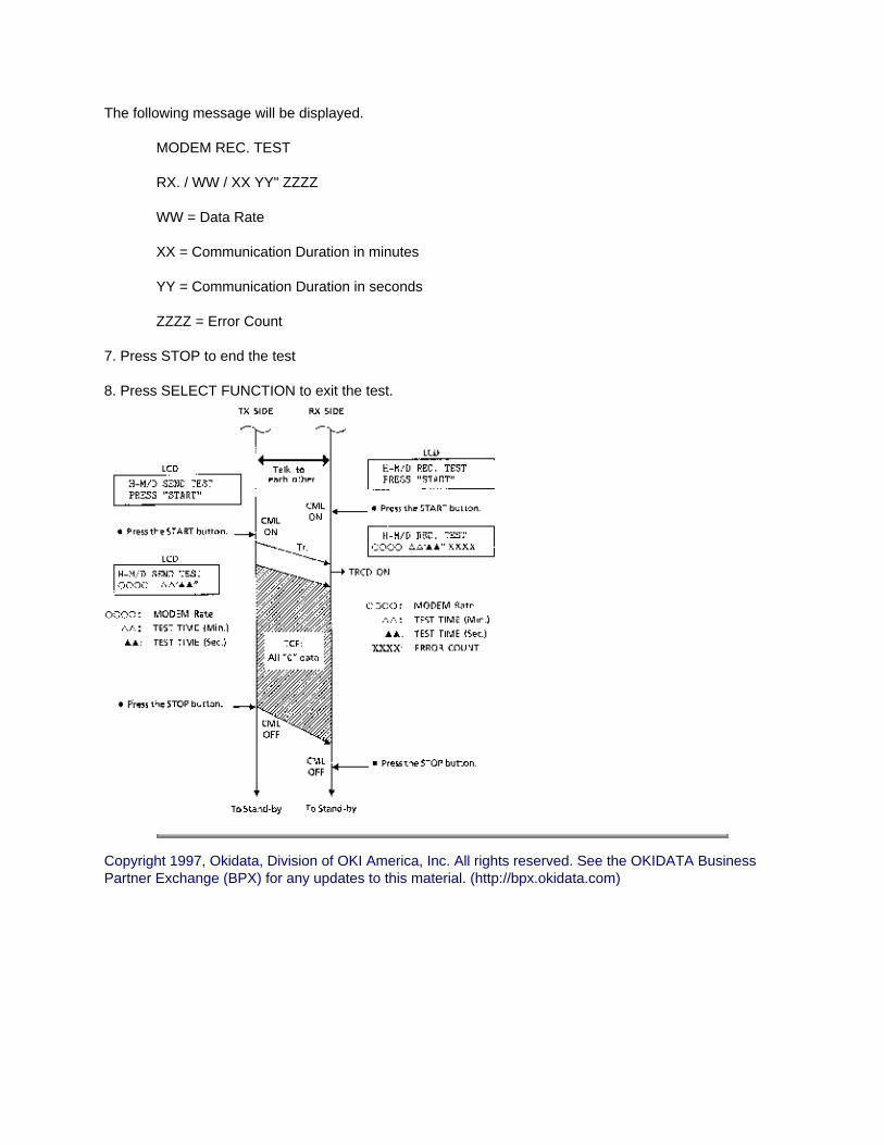
The following message will be displayed.
MODEM REC. TEST
RX. / WW / XX YY" ZZZZ
WW = Data Rate
XX = Communication Duration in minutes
YY = Communication Duration in seconds
ZZZZ = Error Count
7. Press STOP to end the test
8. Press SELECT FUNCTION to exit the test.
Copyright 1997, Okidata, Division of OKI America, Inc. All rights reserved. See the OKIDATA Business Partner Exchange (BPX) for any updates to this material. (http://bpx.okidata.com)

Page: 93
Service Guide OF2200/2400/2600Chapter 2 Failure Analysis
2.6.07 Multi-Frequency Send Test
General InformationThis test is used to verify the operation of the multi-frequency touch-tone signals from the LINE terminal.
Procedure1. Press SELECT FUNCTION.
2. Press COPY twice.
3. Press LEFT ARROW twice.
4. Enter the appropriate number from the numeric pad.
Okifax 2200: 7
Okifax 2400/2600: 05
5. Press LEFT ARROW.
6. Press each key of the ten-key pad keys.
The multi-frequency signal of the key will be continuously sent after each key is pressed.
7. Press STOP to end the test.
8. Press SELECT FUNCTION to exit the test.
Copyright 1997, Okidata, Division of OKI America, Inc. All rights reserved. See the OKIDATA Business Partner Exchange (BPX) for any updates to this material. (http://bpx.okidata.com)

Page: 94
Service Guide OF2200/2400/2600Chapter 2 Failure Analysis
2.6.08 Print Test
General InformationThis tests the printer unit separately from the facsimile device.
If the test fails, refer to RAP 14.
Procedure
1. Press SELECT FUNCTION.
2. Press COPY twice.
3. Press LEFT ARROW twice.
4. Enter the appropriate number from the ten-key pad.
Okifax 2200: 8
Okifax 2400/2600: 10
5. Press LEFT ARROW. After approximately 30 seconds, the test will print.
6. Press STOP once to halt printing.
Printing will continue until the print buffer is empty.
7. Press SELECT FUNCTION to exit the test.
Copyright 1997, Okidata, Division of OKI America, Inc. All rights reserved. See the OKIDATA Business Partner Exchange (BPX) for any updates to this material. (http://bpx.okidata.com)

Page: 95
Service Guide OF2200/2400/2600Chapter 2 Failure Analysis
2.6.09 Voice Message Test
General InformationThis voice message test verifies the proper operation of the units voice message capability. All languages are tested, regardless of the selected language. The voice message function is used in the TEL/FAX Mode.
Procedure
1. Press SELECT FUNCTION.
2. Press COPY twice.
3. Press LEFT ARROW twice.
4. Enter the appropriate number from the ten-key pad.
Okifax 2200: 9
Okifax 2400/2600: 09
5. Press LEFT ARROW.
The following message will be displayed.
9: VOICE MSG. TEST
MESSAGE SENDING
6. Press STOP to end the test.
7. Press SELECT FUNCTION to exit the test.
Copyright 1997, Okidata, Division of OKI America, Inc. All rights reserved. See the OKIDATA Business Partner Exchange (BPX) for any updates to this material. (http://bpx.okidata.com)

Page: 96
Service Guide OF2200/2400/2600Chapter 2 Failure Analysis
2.7 REPORTS
2.7.01 General InformationReports can be used to check operations, settings, and activities of the facsimile machine.This section provides the Service Codes used in the Activity Report and information on the Protocol Dump Report. All other reports are covered in the Users Guides. Please refer to the Users Guides for further details.
The available reports are listed below.
1. Active Memory Files
2. Activity
3. Auto Dial Directory
4. Box List
5. Cancel
6. Communication Codes
7. Configuration
8. Confirmation of Entry
9. Confirmation
10. Error Log
11. Memory Entry
12. Message Confirmation
13. Multiple Location Message Confirmation Report
14. One Touch Directory
15. Personal Box RX
16. Protocol Dump
17. Relay Broadcast
18. Result Codes
Copyright 1997, Okidata, Division of OKI America, Inc. All rights reserved. See the OKIDATA Business Partner Exchange (BPX) for any updates to this material. (http://bpx.okidata.com)

Page: 97
Service Guide OF2200/2400/2600Chapter 2 Failure Analysis
2.7.02 Service Codes List (Activity Report)
The Service Codes are the same for the Okifax 2200, Okifax 2400, and Okifax 2600.
Service Code Type Service Code Group
Normal Termination Service Code (in all modes) 0000
Error While Dialing Phase A 1xxx
G3 Transmission Phase B 2xxx
G3 Reception Phase C 3xxx
G3 Transmission Phase D 41xx
Miscellaneous Service Codes 6xxxx and 9xxx
Code Description
0000 Successful end of communication
1080 STOP key has been pressed while calling a remote fax
10A2 Busy tone detected
14A3 Second dial tone not detected
14C0 Dial tone not detected
14C1 Line current not detected
14C2 Calling-and-waiting for line connection time out
14C3 Dialing limit time out
21A0 Received signal other than DIS/DTC
21A1 Contents of received DIS/DTC are faulty
21A2 TCF is sent three times and DIS/DTC is received each time in response
21A3 TCF is sent three times and the receiver has not responded
21A4 TCF fall-back is not possible

21A5 Received signal other than the desired signal in response to sending TCF
21B0 Transmitter tried to perform Confidential Transmission but the remote receiver is not capable of Confidential Reception
21B1 Transmitter tried to transmit by Broadcast Initiate Function but the remote fax is not capable of Broadcast
21C0 In Closed Network Setting TSI/CIG/CST is either not received or if received it is not authorized
22A6 Tried to perform Polling Reception but could not communicate because the remote fax is G2
22B0 Tried to perform Confidential Transmission but could not communicate because the remote fax is G2
22B1 Tried to perform Relay Broadcast Initiate but could not communicate because the remote fax is G2
22B2 Tried to perform Broadcast but could not communicate because the remote fax is G2
29B1 Confidential Reception was specified by transmitter in Phase B but the amount of available memory was insufficient
29B6 In Confidential Reception the mail box specified by the transmitter is not set up and open
39A0 The number of continuous-error lines have exceeded the specified limit
39A1 The number of random-error lines have exceeded the specified limit
39B0 Memory Overflow has occurred while receiving in memory
39B1 Memory Overflow occurred during Confidential Reception
39C0 Decoder hardware error. (Cannot reproduce picture)
39C1 Decoder hardware error. (Cannot detect end of picture)
41A0 There was no response to the post command in three attempts.
41A3 RTN received in response to the post command
41A6 Received a signal other than the desired signal in response to the post command
41A9 Fall-back in Phase C is not possible
41AA Received PIN for the post command
41C8 T5 time out
41CC Received a signal other than the desired signal in response to RNR
41CD Command not received in response to RNR

41CE Received negative signal in response to the post command
41DB CTC baud rate mismatched
60A0 Broadcast completed
6803 DCN received in response to NSF/DIS without sending a single picture
68A0 Multiple Polling Reception completed
9080 STOP key was pressed during a transmission
9081 T1 time out
9082 T2 time out
9083 T3 time out
9084 No recording paper
9087 Document jam
9088 60 minute or 70 minute time out
9089 Document length has exceeded its maximum limit
908E Recording paper jam
9090 Received DCN
9091 Voltage reversal was detected because of line disconnection
90B1 Picture memory checksum error
90C1 Document removed prior to transmission
90C6 Normal or error-free lines not received for 13 seconds
90C7 Error frame protocol received
90D0 Encoder hardware error (Picture storage fault)
90D1 Encoder hardware error (Cannot detect the end of picture)
90D2 Encoder hardware error (Cannot detect completion of transmission)
90D3 Hardware error in transmission system (Sending protocol signals not completed)
90D4 Hardware error in transmission system (Response of modem not detected)
90E0 Decoder hardware error (Picture storage fault)
90E6 Occurrence of AC power failure
90F0 Engine error
90F1 Fan motor error
90F2 Fuser error
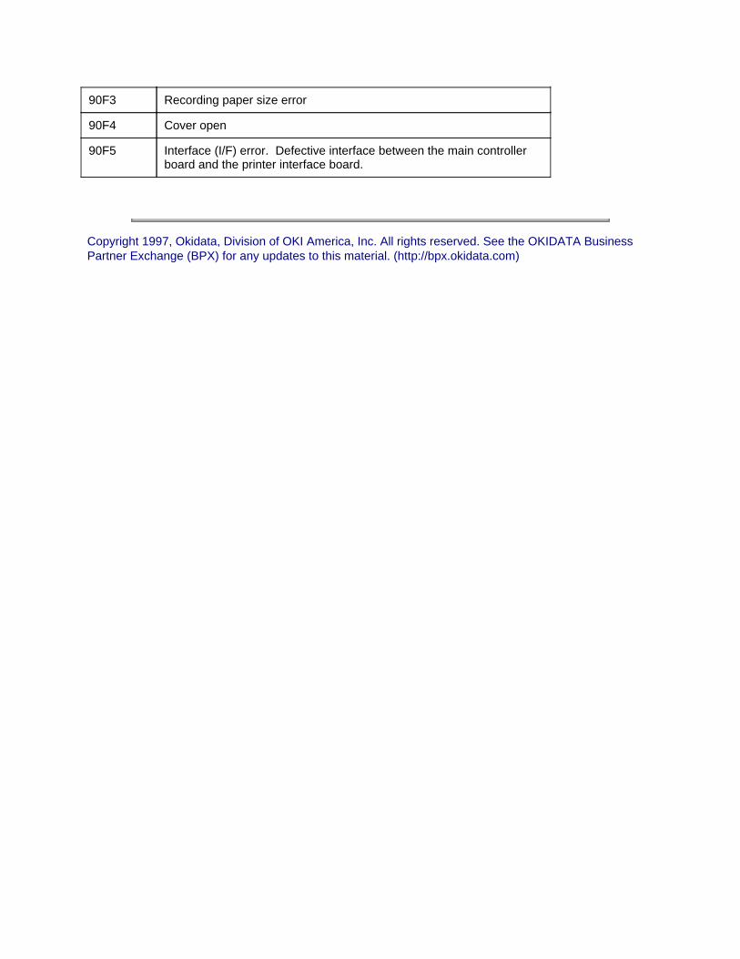
90F3 Recording paper size error
90F4 Cover open
90F5 Interface (I/F) error. Defective interface between the main controller board and the printer interface board.
Copyright 1997, Okidata, Division of OKI America, Inc. All rights reserved. See the OKIDATA Business Partner Exchange (BPX) for any updates to this material. (http://bpx.okidata.com)

Page: 98
Service Guide OF2200/2400/2600Chapter 2 Failure Analysis
2.7.03 Protocol Dump
General InformationThe Protocol Dump Report provides the service technician with a tool to analyze the control signals of G3 protocol transmissions and receptions. This report can be generated manually or automatically (Okifax 2200 ONLY). The Service Bit (Okifax 2200) or the appropriate bit of the Service Parameter (Okifax 2400/2600) must be ON in order to print this report.
Okifax 2200: The Service Bit is Technical Function 27.
Okifax 2400/2600: The Service Parameter is Technical Function 91.
Refer to Section 2.9 for information on setting Technical Functions .
Manual Generation1. Press SELECT FUNCTION.
2. Press the appropriate key.
Okifax 2200: RIGHT ARROW
Okifax 2400/2600: One Touch Key 25
3. Press the appropriate key.
Okifax 2200: "*"
Okifax 2400/2600: "07" from the numeric key pad.
4. Okifax 2400/2600 ONLY
Press RIGHT ARROW
5. Press LEFT ARROW.
6. Press STOP to exit.
Automatic Generation
Okifax 22001. Set Technical Function 02 to ON. Refer to Module 2.9
Okifax 2400/26001. Automatic generation is not possible. This report is only available through a manual generation.

Copyright 1997, Okidata, Division of OKI America, Inc. All rights reserved. See the OKIDATA Business Partner Exchange (BPX) for any updates to this material. (http://bpx.okidata.com)

Page: 99
Service Guide OF2200/2400/2600Chapter 2 Failure Analysis
Facsimile Control Field Conversion Table
This table shows all facsimile control field (FCF) signals which are needed to analyze the printed protocol dump data.
Some signals have two different hexadecimal codes, in accordance with the calling party or called party.
The signals are the same for the Okifax 2200, Okifax 2400, and Okifax 2600.
Abbreviation Hexadecimal Codes
Description of Function
NSF 04 Non-Standard Facilities
CSI 02 Called Subscriber Identification
DIS 01 Digital Identification Signal
NSC 84 Non-Standard Facilities Command
CIG 82 Calling Subscriber Identification
DTC 81 Digital Transmit Command
NSS 44 C4 Non-Standard Set-up
TSI 42 C2 Transmitting Subscriber Identification
DCS 41 C1 Digital Command Signal
CFR 21 A1 Confirmation to Receive
MCF 31 B1 Message Confirmation
FTT 22 A2 Failure to Train
MPS 72 F2 Multi-Page Signal
EOM 71 F1 End of Message
EOP 74 F4 End of Procedure
RTP 33 B3 Retrain Positive
RTN 32 B2 Retrain Negative
PIP 35 B5 Procedure Interrupt Positive
PIN 34 B4 Procedure Interrupt Negative
PRI-MPS 7A FA Procedure Interrupt-MPS
PRI-EOM 79 F9 Procedure Interrupt-EOM

PRI-EOP 7C FC Procedure Interrupt-EOP
DCN AF DF Disconnect
CRP 58 D8 Command Repeat
CTC 48 C8 Continue to Correct
CTR 23 A3 Response to Continue to Correct
EOR 73 F3 End of Retransmission
ERR 38 B8 Response to End of Retransmission
FCD 60 Facsimile Coded Data
PPS 7D FD Partial Page Signal
PPR 3D BD Partial Page Request
RCP 61 Return to Control for Partial Page
RNR 37 B7 Receive Not Ready
RR 76 F6 Receive Ready
Copyright 1997, Okidata, Division of OKI America, Inc. All rights reserved. See the OKIDATA Business Partner Exchange (BPX) for any updates to this material. (http://bpx.okidata.com)

Page: 100
Service Guide OF2200/2400/2600Chapter 2 Failure Analysis
2.8 RESETS
WARNING:Although there is a PRINTER COUNTER RESET available, DO NOT reset the counter. This counter is used to keep track of the total number of printed pages.
The Service Bit (Okifax 2200) or the appropriate bit of the Service Parameter (Okifax 2400/2600) must be set to ON before resetting any counters.
Okifax 2200: Technical Function 27
Okifax 2400/2600: Technical Function 91
Refer to Module 2.9 for information regarding the Service Bit / Service Parameter.
Copyright 1997, Okidata, Division of OKI America, Inc. All rights reserved. See the OKIDATA Business Partner Exchange (BPX) for any updates to this material. (http://bpx.okidata.com)

Page: 101
Service Guide OF2200/2400/2600Chapter 2 Failure Analysis
2.8.01 General Information
The following unit counters must periodically be reset.
1. Toner Counter
2. Drum Counter
3. Fuser Counter
Viewing the CountersTo view the counters (without resetting), follow this procedure.
Okifax 2200
1. Press SELECT FUNCTION.
2. Press RIGHT ARROW.
3. Press LEFT ARROW.
4. Enter the appropriate number from the numeric keypad.
6 Print Counter
7 Drum Counter
8 Fuser Counter
9 Toner Counter
5. Press LEFT ARROW or number of counter.
The counter displays for five seconds.
6. Press SELECT FUNCTION to exit OR Enter the number of another counter to view.
Okifax 2400/2600
1. Press SELECT FUNCTION.
2. Press One Touch Key 28.
The following message will appear.
1. PRINT COUNT

NEXT ( ¬ / 1-4 ) CLEAR ( ® )
3. Press LEFT ARROW or number of counter to view.
1 Print
2 Toner
3 Drum
4 Fuser
4. Press SELECT FUNCTION to exit OR Enter the number of another counter to view.
Copyright 1997, Okidata, Division of OKI America, Inc. All rights reserved. See the OKIDATA Business Partner Exchange (BPX) for any updates to this material. (http://bpx.okidata.com)

Page: 102
Service Guide OF2200/2400/2600Chapter 2 Failure Analysis
2.8.02 Toner Counter Reset
General InformationReset the Toner Counter whenever a new toner cartridge is installed.
ProcedureTo reset this counter, perform the following actions.
NOTE:The Service Bit (Okifax 2200) or the appropriate bit of the Service Parameter (Okifax 2400/2600) must be set to ON to reset this counter. (Refer to Module 2.9 )
Okifax 2200 1. Press SELECT FUNCTION.
2. Press RIGHT ARROW twice.
3. Enter "8" from the numeric keypad.
4. Press LEFT ARROW.
The following message will be displayed.
1: TONER COUNT CLEAR?YES ( ¬ ) NO ( ® 1-4)
5. Press LEFT ARROW.
The following message will be displayed.
ARE YOU SURE?YES ( ¬ ) NO ( ® )
6. Press LEFT ARROW to reset the counter.
7. Press SELECT FUNCTION to exit the procedure.
Okifax 2400/2600
1. Press SELECT FUNCTION.
2. Press One Touch Key 28.
3. Enter "2" from the numeric keypad.

The following message will be displayed.
2: TONER COUNT = XXXXXXNEXT ( ¬ / 1 - 4 ) CLEAR ( ®)
4. Press RIGHT ARROW.
The following message will be displayed.
2: TONER COUNT CLEAR?YES ( ¬ ) NO ( ® )
5. Press LEFT ARROW.
The following message will be displayed.
ARE YOU SURE?YES ( ¬ ) NO ( ® )
6. Press LEFT ARROW to reset the toner counter.
7. Press SELECT FUNCTION to exit the procedure.
Copyright 1997, Okidata, Division of OKI America, Inc. All rights reserved. See the OKIDATA Business Partner Exchange (BPX) for any updates to this material. (http://bpx.okidata.com)

Page: 103
Service Guide OF2200/2400/2600Chapter 2 Failure Analysis
2.8.03 Drum Counter Reset
General InformationReset the Drum Counter whenever image drum cartridge is replaced.
ProcedureTo reset this counter, perform the following actions.
NOTE:The Service Bit (Okifax 2200) or the appropriate bit of the Service Parameter (Okifax 2400/2600) must be set to ON to reset this counter. (Refer to Module 2.9)
Okifax 2200
1. Press SELECT FUNCTION.
2. Press RIGHT ARROW twice.
3. Enter "8" from the numeric keypad.
4. Press LEFT ARROW.
The following message will be displayed.
1: TONER COUNT CLEAR?YES ( ¬ ) NO ( ® 1-4)
5. Enter "2" from the numeric keypad.
6. Press LEFT ARROW.
The following message will be displayed.
ARE YOU SURE?YES ( ¬ ) NO ( ® )
7. Press LEFT ARROW to reset the counter.
8. Press SELECT FUNCTION to exit the procedure.
Okifax 2400/2600
1. Press SELECT FUNCTION.
2. Press One Touch Key 28.

3. Enter "3" from the numeric keypad.
The following message will be displayed.
3: DRUM COUNT = XXXXXXNEXT ( ¬ / 1 - 4 ) CLEAR ( ®)
4. Press RIGHT ARROW.
The following message will be displayed.
3: DRUM COUNT CLEAR?YES ( ¬ ) NO ( ® )
5. Press LEFT ARROW.
The following message will be displayed.
ARE YOU SURE?YES ( ¬ ) NO ( ® )
6. Press LEFT ARROW to reset the counter.
7. Press SELECT FUNCTION to exit the procedure.
Copyright 1997, Okidata, Division of OKI America, Inc. All rights reserved. See the OKIDATA Business Partner Exchange (BPX) for any updates to this material. (http://bpx.okidata.com)
Page: 104
Service Guide OF2200/2400/2600Chapter 2 Failure Analysis
2.8.04 Fuser Counter ResetGeneral InformationReset the Fuser Counter whenever the Fuser Unit is replaced.
ProcedureTo reset this counter, perform the following actions.
NOTE:The Service Bit (Okifax 2200) or the appropriate bit of the Service Parameter (Okifax 2400/2600) must be set to ON to reset this counter. (Refer to Module 2.9)
Okifax 2200
1. Press SELECT FUNCTION.
2. Press RIGHT ARROW twice.
3. Enter "8" from the numeric keypad.
4. Press LEFT ARROW.
The following message will be displayed.
1: TONER COUNT CLEAR?YES ( ¬ ) NO ( ® 1-4)
5. Enter "3" from the numeric keypad.
6. Press LEFT ARROW.
The following message will be displayed.
ARE YOU SURE?YES ( ¬ ) NO ( ® )
7. Press LEFT ARROW to reset the counter.
8. Press SELECT FUNCTION to exit the procedure.
Okifax 2400/2600
1. Press SELECT FUNCTION.
2. Press One Touch Key 28.
3. Enter "4" from the numeric keypad.

The following message will be displayed.
4: FUSER COUNT = XXXXXXNEXT ( ¬ / 1 - 4 ) CLEAR ( ®)
4. Press RIGHT ARROW.
The following message will be displayed.
4: FUSER COUNT CLEAR?YES ( ¬ ) NO ( ® )
5. Press LEFT ARROW.
The following message will be displayed.
ARE YOU SURE?YES ( ¬ ) NO ( ® )
6. Press LEFT ARROW to reset the counter.
7. Press SELECT FUNCTION to exit the procedure.
Copyright 1997, Okidata, Division of OKI America, Inc. All rights reserved. See the OKIDATA Business Partner Exchange (BPX) for any updates to this material. (http://bpx.okidata.com)

Page: 105
Service Guide OF2200/2400/2600Chapter 2 Failure Analysis
2.8.05 System Reset
General Information
CAUTION:Performing a System Reset will cause the loss of all programmed user and service data.ALL programmable feature are reset to factory default settings.
Print a copy of the reports listed below before resetting the system. These reports provide a record of all programmed features.
Configuration Report
Auto Dial List
One Touch List
A System Reset clears the Random Access Memory (RAM)
The Service Bit (Okifax 2200) or the appropriate bit of the Service Parameter (Okifax 2400/2600) must be set to ON to reset this counter. (Refer to Module 2.9)
ProcedureIn order to perform a system reset, follow this procedure.
1. Print the Configuration Report, the Auto Dial List, and the One Touch List.
2. Press SELECT FUNCTION.
3. Press COPY twice.
4. Press the "3" key.
The following message will be displayed.
SYSTEM RESET ?
5. Press LEFT ARROW.
6. Press one of the following keys.
Okifax 2200
Press LEFT ARROW: ALL DATA CLR.

Press the "2" key: LOCATION DATA CLR.
Press the "3" key: CONFIG DATA CLR.
Press the "4" key: TX PAGES CLR.
Press the "5" key: RX PAGES CLR.
Okifax 2400/2600
Press LEFT ARROW: ALL DATA CLR.
Press the "2" key: LOCATION DATA CLR.
Press the "3" key: MESSAGE DATA CLR.
Press the "4" key: CONFIG DATA CLR.
Press the "5" key: TX PAGES CLR.
Press the "6" key: RX PAGES CLR.
7. Press LEFT ARROW.
The following message will be displayed.
ARE YOU SURE?
8. Press LEFT ARROW to CLEAR the selected data
9. Press SELECT FUNCTION to exit the procedure.
Copyright 1997, Okidata, Division of OKI America, Inc. All rights reserved. See the OKIDATA Business Partner Exchange (BPX) for any updates to this material. (http://bpx.okidata.com)

Page: 106
Service Guide OF2200/2400/2600Chapter 2 Failure Analysis
2.9 TECHNICAL FUNCTION SETTINGS
2.9.01 Accessing the Technical Function Settings
In order to access the Technical Function settings, perform the following actions.
1. Press SELECT FUNCTION.
2. Press COPY twice.
3. Press LEFT ARROW.
4. Press RIGHT ARROW.
5. Press LEFT ARROW.
The following message will be displayed.
Okifax 2200FUNCTION NUMBER? [ ]01 - 45
Okifax 2400/2600FUNCTION NUMBER? [ ]01 - 91
6. Enter the number of the desired technical function ("01" not "1")
7. Press RIGHT ARROW to select the desired setting for the Technical Function.
8. Press LEFT ARROW to store the selected setting and display the next function.
9. Press SELECT FUNCTION to exit the procedure.
Copyright 1997, Okidata, Division of OKI America, Inc. All rights reserved. See the OKIDATA Business Partner Exchange (BPX) for any updates to this material. (http://bpx.okidata.com)

Page: 107
Service Guide OF2200/2400/2600Chapter 2 Failure Analysis
List of Technical Functions - Okifax 2200
Name Purpose Default
01 Line Monitor Control Selects the monitoring range. <R> ON Off-Hook to DCN<R>OFF: Off-Hook to DIS
OFF
02 Automatic Protocol Dump Select
Reports handshaking and protocol data for each communication
OFF
03 Automatic MCF Enables automatic printout of the Message Confirmation Report upon detecting a communication error
ON
04 TSI Print Selects the printing of TSI data from the sending FAX on the received picture. TSI is printed at the leading edge of the first page only.
ON
05 Reverse Polling Selects the reverse poll function<R> OFF
06 Continuous Polling Placing a document on the ADF tray selects the polling mode without operating the SELECT FUNCTION Key.<R>Allows continuous loop RX poll of auto-dial group.
OFF
07 MH Only Limits image compression to Modified Huffman Code only.<R>
OFF
08 Shorten Protocol Shortens protocol to save transmission time.<R> ON
09 Call-Back Message Enables sending a voice callback request when the remote station does not respond to a Voice Request.
ON
10 Personal ID Enables the transmission of the upper 16 characters of the sender ID as the Personal ID. The Personal ID will appear on the remote station's display and on the remote station's Activity Report.
ON
11 Relay Broadcast Initiate
Enables/disables Relay Broadcast Function prompts.
ON
12 Confidential TX Enables the Confidential TX Function. ON
13 H-Modem Rate Selects the modem's starting speed: 9600 or 4800 bps.
9600

14 Ignoring the First DIS
This function can be selected to compensate for poor phone line quality.<R>This function causes the Okifax 2200 to ignore the first DIS and "listen" for the second DIS. This allows time for line echo to settle so a clear DIS can be recognized.
OFF
15 Interval Between CED and DIS
Settings: 75 ms or 1.5 seconds. Use 1.5 Seconds if poor quality phone lines are encountered.
75 ms
16 Protective Tone Against the Echo Suppresser
This tone enables the telco echo suppressers to compensate for echo on overseas lines. Please note that this is a "global" setting affecting all calls. This function is also available as a one-touch parameter.
OFF
17 Manual TX CNG Used in selecting the function of the CNG signal from the transmitter during manual transmission.
ON
18 Manual RX CED Used in selecting the function of the CED signal from the receiver during manual reception.
OFF
19 Off-Hook Bypass Allows communications to be established without having the handset installed.
OFF
20 Long Document TX Long Document Transmission Select:<R>ON: 60 minutes maximum<R>OFF: 14 inches maximum
OFF
21 Attenuator Adjusts the attenuation of the transmit signal power level.<R>Settings: 0 to 15 dB (in 1 dB increments).
10 dB
22 Non-Loaded (NL) Equalizer
Selects the equalizing level of the received signal. Settings: 0 4 8 or 12 dB.
4 dB
23 Document Top Feed Adjusts the Start of Scan Position of the ADF.<R>Settings: -7 to +10 mm (in 1 mm increments.)
0 mm
24 Document End Feed Adjusts the End of Scan Position of the ADF.<R>Settings: -7 to + 10 mm (in 1 mm increments).
0 mm
25 Sensor Calibration Select ON to enable calibration of the scanner sensor (CIS).<R>This setting returns to OFF once the scanner calibration procedure has been executed.
OFF
26 Phone Dial Switches the alternate FAX telephone number to a regular phone number for voice communication.
OFF
27 Service Bit ON: Technician's features are available.<R>OFF: Technician's features are not available.
OFF

28<$!B02>
Video Parameter<$!B02>
FACTORY USE ONLY<R><$!B02> N/A<$!B02>
29 MDY / DMY Selects the format of the date displayed on the operator panel and printed on reports.<R>Settings:<R><_><_>MDY: Month/Day/Year<R><_><_>DMY: Day/Month/Year
MDY
30 CCITT ECM Enables the use of the CCITT Error Correction Mode.
ON
31 Receive in Memory Enables the Memory RX Function when the following occur.<R><_><_>NO PAPER<R><_><_>COVER OPEN<R><_><_>PAPER JAM
ON
32 Page Retransmission
Enables page retransmission from memory if a communications error exists in non-ECM mode.
ON
33 Local Date and Time Print
Prints the Date/Time at the top of the first received page.<R>Settings: OFF ONCE ALL
OFF
34 T1<_>T0 Value Selects the time duration (in seconds) that the Okifax 2200 will wait for a remote station's answer.
000
35 Receive in Memory when Low Toner Condition Exists
Enables the Memory RX Function when a low toner condition exists.
ON
36 RX Error Message Print
Enables printing the message RECEIVE STOPPED when reception is interrupted.
ON
37 MMR Function Enables/disables MMR communication ON
38 75% Reduction Enables/disables 75% reduction (legal to letter reduction)
ON
39 Print Counter on LCD in the stand-by mode
Displays the value of the print counter on the operator panel while the Okifax 2200 is in the idle mode.
OFF
40 Voice Message Attenuator<R><R><R>
Adjusts the attenuation for the voice message power level. Settings: 0 to 15 dB (in one dB increments).
10 dB
41 Real-time Dialing Selects one of three dialing capabilities. TYPE 2
TYPE 1: Dialing is available when the handset is OFF-HOOK.
TYPE 2: Dialing is available when the handset is OFF-HOOK or press the HOOK Key.

OFF
42 Ring Duration Detection Time
Selects the minimum Ring Detection Time.<R>Settings: 10 msec. to 120 msec. (in 10 msec. increments).
120 msec.
43 CML Timing Sets the time from the end of the ring to CML ON.<R>Settings: 00 to 990 msec. (in 10 msec. increments.)
300 msec.
44 Activity Report Distant ID Printing
For security purposes enables/disables the printing of the distant ID in the activity report. This function applies to message confirmation reports confidential receive reports and power off reports.
ON
45 TAD Mode Enables/disables the TAD Mode. TAD Mode is activated when Auto RX Mode is selected.
ON
Copyright 1997, Okidata, Division of OKI America, Inc. All rights reserved. See the OKIDATA Business Partner Exchange (BPX) for any updates to this material. (http://bpx.okidata.com)

Page: 108
Service Guide OF2200/2400/2600Chapter 2 Failure Analysis
List of Technical Functions - Okifax 2400/2600
# Name Specifications Default
01 Message Confirmation Report (Single Location)
Enables (ON) or disables (OFF) the automatic printing of the Message Confirmation Report after a single location call.
OFF
02 Message Confirmation Report (Multiple Locations)
Enables (ON) or disables (OFF) the automatic printing of the Message Confirmation Report after a broadcast or multiple polling.
ON
03 Error Report (MCF) Enables (ON) or disables (OFF) printing the Message Confirmation Report when a communication error occurs.
ON
04 Message in Error Report (MCF)
Enables (ON) or disables (OFF) printing the Disconnected message in the Error Report when Technical Functions 1 or 3 show a communication error in memory TX.
ON
05 Personal Box Reception Report
Enables (ON) or disables (OFF) the automatic printing of the Reception Report when a confidential message is received in the personal box.
ON
06 Entry Report Enables (ON) or disables (OFF) the automatic printing of the Entry Report. This report prints when a delayed transmission occurs. This includes batch transmissions batch receptions broadcasts or multi-polling receptions.
ON
07 Cover Letter Enables (ON) or disables (OFF) printing a message on the cover letter. The available messages are listed below. NO: No message printed. CB: PLEASE CALL BACK printed. URG: URGENT printed. CONF: CONFIDENTIAL printed.
OFF
08 Activity Report (Full Print)
Enables (ON) or disables (OFF) the automatic printing of the Activity Report when 50 (NORMAL) or only error (ERROR) communications have been recorded in the internal memory.
NORM

09 Distant Station ID Enables (ON) or disables (OFF) printing the distant station ID on reports (Activity and Message Confirmation). This is often used as a security measure.
ON
10 Line Monitor Volume Controls the volume. Settings: OFF LOW or HIGH
LOW
11 Buzzer Volume Adjusts the volume of the following: touch tone of each key end of communication buzzer voice request buzzer and off-hook alarm. Settings: HIGH or LOW.
LOW
12 Key Touch Response Enables (ON) or disables (OFF) the volume of the tone of each touch key.
ON
13 Sender ID The unit can transmit a programmed alphanumeric message (such as a company's name) 32 characters in length. This known as the Sender ID. The Sender ID may be printed inside (IN) or outside (OUT) of the copied documentation area. Settings: OUT IN OFF
OUT
14 TX Mode Default Selects the default transmission mode. Settings: (a) NORMAL LIGHT or DARK (b) STD FINE or EX. FINE (c) PHOTO or non-PHOTO( if FINE is selected).
NORMAL STD and non- PHOTO
15 Memory and Feeder Selection Switching
Selects the transmission method Settings: MEM or FEED NOTE: If Verification Stamp (Technical Function 18) is set to ON Technical Function 15 - MEMORY transmit will be disabled. To perform a MEMORY (Quick Scan) transmission while Verification Stamp is ON load the document press SELECT FUNCTION then press One Touch Key 01. This will allow a one time memory transmit session.
MEM.
16 No Reduction Transmission
When this function is enabled (ON) the following occurs. If the width of the document being sent is larger than the receiving station's capabilities only the center area of the document is scanned and transmitted. No reduction occurs. Text outside of the receiver's capabilities is lost.
OFF
17 Long Document TX Enables (ON) or disables (OFF) transmitting long sized documents. ON: 60 minutes maximum. OFF: 500 mm minimum.
OFF

18 Verification Stamp Enables (ON) or disables (OFF) printing a circular mark near the bottom of the page when an MCF RTP or PIP is received in response to a page being sent. A printed stamp indicates successful TX. NOTE: If Verification Stamp (Technical Function 18) is set to ON Technical Function 15 - MEMORY transmit will be disabled. To perform a MEMORY (Quick Scan) transmission while Verification Stamp is ON load the document press SELECT FUNCTION then press One Touch Key 01. This will allow a one time memory transmit session.
OFF
19 Page Re-transmission Enables (ON) or disables (OFF) page retransmission from memory if a communications error exists in non-ECM mode.
ON
20 Communication Error Redial
Enables (ON) or disables (OFF) redialing when memory transmission fails.
ON
21 Closed Network Reception
The lower four digits of the TSI/CSI (from the remote station) are compared with the registered one touch and auto dial numbers of the local station. If the numbers do not match the communication will disconnect.
OFF
22 Relay Station Okifax 2600 ONLY
Enables (ON) or disables (OFF) the relay key station function.
OFF
23 Print Relay Message Okifax 2600 ONLY
Enables (ON) or disables (OFF) printing the relay message when the fax handled the message as a relay station. This function is available ONLY on the Okifax 2600.
OFF
24 Relay Key Word Okifax 2600 ONLY
Sets the relay key word four digit password for relay operation for relay transmission.
0000
25 Print Forward Message Enables (ON) or disables (OFF) printing the forward message when the forward message communication is completed.
OFF
26 No Paper Reception Enables (ON) or disables (OFF) storing received messages in memory when the reception mode (One Touch Key 21) is selected as print mode.
ON
ON: RX messages are stored in memory when the following occur: No Paper Cover Open Paper Jam.
OFF: Messages are not stored.
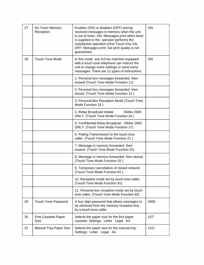
27 No Toner Memory Reception
Enables (ON) or disables (OFF) storing received messages in memory when the unit is out of toner. ON: Messages print when toner is supplied or the operator performs the substitutive operation (One Touch Key 24). OFF: Messages print but print quality is not guaranteed.
ON
28 Touch Tone Mode In this mode any G3 fax machine equipped with a touch tone telephone can instruct the unit to change some settings or send some messages. There are 11 types of instructions.
ON
1. Personal box messages forwarded then erased (Touch Tone Mode Function 11)
2. Personal box messages forwarded then stored. (Touch Tone Mode Function 12 )
3. Personal Box Reception Mode (Touch Tone Mode Function 15 )
4. Relay Broadcast Initiate Okifax 2600 ONLY. (Touch Tone Mode Function 16 )
5. Confidential Relay Broadcast Okifax 2600 ONLY. (Touch Tone Mode Function 17)
6. Polling Transmission to the touch tone caller (Touch Tone Mode Function 21 )
7. Message in memory forwarded then erased. (Touch Tone Mode Function 31)
8. Message in memory forwarded then stored. (Touch Tone Mode Function 32 )
9. Temporary cancellation of closed network. (Touch Tone Mode Function 81 )
10. Reception mode set by touch tone caller. (Touch Tone Mode Function 91)
11. Personal box reception mode set by touch tone caller. (Touch Tone Mode Function 92)
29 Touch Tone Password A four digit password that allows messages to be retrieved from the memory reception box by a touch-tone caller.
0000
30 First Cassette Paper Size
Selects the paper size for the first paper cassette. Settings: Letter Legal A4.
LET
31 Manual Tray Paper Size Selects the paper size for the manual tray. Settings: Letter Legal A4.
LEG

32 NOT USED NOT USED
33 Copy Split Printing In the copy mode a document longer than the printing length of the recording paper is printed on multiple pages.
ON
ON: Split printing occurs.
OFF: The part of the document beyond the first recording page will not be printed.
34 RX Split Printing When a received document is longer than the available printing length of the recording paper the document prints on two or more pages.
ON
ON: Split printing occurs.
OFF: The part of the document beyond the first recording page will not be printed.
35 RX Reduction Printing Specifies the maximum reduction ratio used when printing a received message or disables the RX reduction printing function. Settings: 90% 76% OFF.
76%
36 Repeat Printing When a document is split and printed on two or more pages the end of the preceding page will be printed at the top of the following page. Settings: 5 mm 10 mm OFF.
10 mm
37 Date and Time Printing Enables (ON) or disables (OFF) printing the local date and time at the top of each received page.
OFF
38 TSI Printing Enables (ON) or disables (OFF) printing TSI data on the received page. TSI is printed at the leading edge of each page. (Set at receiver.)
ON
39 Stop Message Printing (RX Error Message Printing)
Enables (ON) or disables (OFF) printing "RECEIVE STOP" on the last page printed when reception is interrupted.
ON
40 Sorting Copies Enables (ON) or disables (OFF) sorting copies when multiple copies are programmed for multiple documents.
ON
41 MF (Tone) or DP (Pulse)
Selects multi-frequency or dial pulse dialing. MF
42 DP (Pulse) Rate Selects the dialing pulse rates. Settings: 10 16 or 20 pps
10 PPS
43 Redial Times Selects the redial times according to the installed country's regulations. Settings: 0 to 15 tries (one try increments).
3 tries.

44 Redial Interval Switches the redial interval to meet the installed country's regulations. Settings: 0 to 15 minutes (one minute increments).
3 min.
45 Timeout Timer Defines the interval between completion of dialing and the start of TX or polling RX communication AND the line hold time for a telephone call in ON-HOOK. Settings: 20 to 90 seconds (one second increments).
59 sec.
46 Parameters for One Touch or Auto Dial Keys
Selects the One Touch Keys or the Auto Dial Keys. Assigns the following features to each One Touch Key and each Auto Dial Key. (a) Starting Modem Rate <_><_>Settings: 14.4 9.6 or 4.8 kbps (b) Ignoring the 1st DIS. <_><_>ON: 1st DIS ignored. <_><_>OFF: 1st DIS is not ignored. (c) Protective Tone (d) MH Only <_><_>ON: Coding scheme is MH only. <_><_>OFF: Either MH MR or MMR
14.4 kbps OFF OFF OFF
47 Department ID This function can restrict operation to only authorized users. It can also record user / department identifiers. Settings: OFF ON Restrict Access ON Restrict Access OFF. When Department ID is ON and Restrict Access is ON unit operation is restricted to authorized users. Users must enter a pre-registered code to operate the unit. Twenty-four codes (01 to 24) can be entered. Each code is a four digit number (0000 to 9999). The twenty-four digit codes and their four digit numbers appear on the Activity Report. NOTE: Service technicians can enter "****' from the operator panel (when the Department ID and Restrict Access are set to ON) to access unit functions.
OFF
48 Message Save Days Selects the period for keeping received messages in the memory. When set to OFF messages are retained in memory indefinitely. Settings: OFF 10 20 or 30 days
20 days
49 Time Out Message Settings: ERASE or PRINT. After being held in memory for the interval specified by Technical Function 48 one of the following will occur. ERASE: Messages erased without printing. PRINT: Messages print and then are erased.
50 Remote Diagnosis Enables (ON) or disables (OFF) the remote diagnosis function.
OFF
51 Power Save Mode Enables (ON) or disables (OFF) the power save mode.
OFF

ON: The fax unit receives all messages in memory reception mode. Print starts at the end of reception and after completion of fuser preheat.
OFF: Power Save Mode disabled.
52 Calendar Format Selects the format of the date displayed on the operator panel and printed on reports. Settings: <_><_>D/M/Y Day Month Year <_><_>Y/M/D Year Month Day <_><~><~>M/D/Y Month Day Year
M/D/Y
53 Continuous Polling RX Enables (ON) or disables (OFF) continuous polling rx. During continuous polling RX the unit polls multiple locations one after another in a loop until the STOP key is pressed.
OFF
54 Priority Copy Enables (ON) or disables (OFF) continuing local copy when an incoming call arrives.
OFF
ON: The incoming call is held until copying is complete. If the call is continued after the end of copy reception starts.
OFF: The copy is stopped when incoming call arrives and automatic restart of copy is not allowed.
55 Select Language Selects the language for operator panel and print messages. Settings: English German Dutch Italian French Swedish Norwegian Danish
ENGLISH
56 Select Voice Message Selects the language of the voice message which responds to the calling station's operator in TEL/FAX switching mode. Settings: English German Dutch Italian French Swedish Norwegian Danish American or OFF
American
57 Modem Attenuator Adjusts the attenuation (dB) for the message send signal power level. The maximum send signal power level (dB) of the fax is 0 dB. Settings: 0 to 15 dB (in 0.5 dB increments). NOTE: The send signal power level must meet your country's regulations. Some countries may specify the input power level at a telephone exchange. In that case subtract the specified level from the line cable attenuation to determine the send level of your fax.
11 dB

58 MF Attenuator Adjusts the attenuation (dB) for the MF tone send signal power level. Settings: 0 to 15 dB (in one dB increments).
3 dB
59 Voice Attenuator Adjusts the attenuation (dB) for the voice message send signal power level. Settings: 0 3 6 9 12 or 15 dB.
12 dB
60 Non-Loaded (NL) Cable Equalizer
Determines the equalizing level of the receiving signal. The equalizing level is the difference of gains of signal between 0.3 kHz and 3.4 kHz Settings: 0 4 8 and 12 dB. NOTE: By this adjustment you can give the inverse characteristics of the non-loaded cable.
4 dB
61 PBX Mode ON: Function enabled. <_><_> Unit connected to a private branch exchange. OFF: Function disabled. <_><_> Unit connected to an outside line.
OFF
62 PBX/PTT Change Selects the PBX type to meet the exchange requirements. Settings: NORMAL GROUND or FLASH.
NORMAL
63 Access Digit Prefix dialing digits used by PBX to connect fax to the public line.
OFF
64 Telephone/Fax Automatic Switch Over Timer
Specifies the time interval when the fax alerts you to the reception of a call in the telephone/fax automatic switch-over mode. Settings: OFF 20 sec. or 35 sec.
20 sec.
65 Ring Response Time Selects the ring response time. Settings: 1 ring 5 10 15 20 25 or 30 sec.
1 ring
66 Auto Start Enables (ON) or disables (OFF) of dialing without pressing the START key in one touch dial and three-digit auto dial mode.
ON
67 Busy Tone Detect Selects the busy tone detection. AUTO
AUTO: This function is enabled or disabled by the PTT parameter setting (One Touch Key 40).
OFF: This function is ignored.
68 Dial Tone Detect Selects the dial tone detection. OFF
AUTO: This function is enabled or disabled by the PTT parameter setting (One Touch Key 40).
OFF: This function is ignored.

69 RS-232-C Mode Specifies the RS-232-C mode.
NOTE: This setting is available to the operator ONLY when the optional RS-232-C board is installed in the unit.
A.<_>OFF OFF
B.<_>Encryption Mode
C.<_>Modem MUX Mode: CE / CF Mode
CF
<_><_>TX Rate: 9.6 7.2 4.8 or 2.4 kpbs 9.6 kpbs
D.<_>Dump Mode
Scanner Mode: Local or Remote Local
Printer Mode: Resolution: STD or FINE STD
Scanner and Printer Mode: TX Rate: 9.6 7.2 4.8 or 2.4 kpbs
9.6 kpbs
E.<_>ASCII Printer Mode
Bell 212A XON - XOFF or DTR Mode XON - XOFF
Stop Bit: 1 or 2 bit 1 bit
TX Rate: 4.8 2.4 1.2 0.3 kpbs 4.8 kpbs
70 Not assigned
71 Not assigned
72 Not assigned
73 Not assigned
74 Line Monitor Control Changes the audible monitoring range. ON: CML-ON to DCN<_><_><_><_><_>OFF: CML-ON to DIS
OFF
75 MH Only When enabled image compression is limited to Modified Huffman (MH) Code ONLY. ON: MH only.<_><_><_><_><_><_><_><_>OFF: MH MR or MMR.
OFF
76 Shorten Protocol When enabled shortens protocol to save transmission time. Protocols are Short Cut and High Speed.
ON
77 CCITT ECM Enables (ON) or disables (OFF) the use of the CCITT Error Correction Mode.
ON

78 Ignoring the first DIS This function can be selected to compensate for poor phone line quality. It causes the unit to ignore the first DIS and "listen" for the second DIS. This allows time for the line echo to settle so a clear DIS can be recognized.
OFF
79 Interval between CED and DIS
Selects the length of the interval between CED and DIS. Use 1.5 seconds if phone lines are poor quality. Settings: 75 ms or 1.5 seconds.
75 ms
80 Protective Tone against the Echo Suppresser
This tone enables the telco echo suppressers to compensate for echo on overseas lines. This function is available as a one touch parameter. NOTE: This is a "global" setting. It affects all calls.
OFF
81 Off-Hook Bypass Allows communications to be established without having the handset installed.
OFF
82 Leased Line Enables (ON) or disables (OFF) the function of the leased line.
OFF
83 PIS/CNG Change Selects a PIS signal or a CNG signal for the leased line mode. PIS: Procedure interrupt signal CNG: Calling tone
PIS
84 Sensor Calibration When set to ON the unit can perform a calibration of the scanner sensor (CIS). This setting returns to OFF once the scanner calibration procedure has been executed.
OFF
85 Scatter Error Specifies the allowable percentage of line error for one page of the document during reception. Settings: 5 to 15% (in 1% increments).
7%
86 High-Speed Modem Rate
Specifies the modem's starting speed. Settings: 14.4k 9.6k or 4.8 kbps.
14.4 kbps
87 National Code A choice of 23 countries. This function selects each country's telephone network condition automatically to meet PTT approval. Settings: U.K. Norway Sweden Australia U.S.A Belgium Netherlands Switzerland Austria Spain Italy Greece Denmark Germany France Int'l-A China Canada New Zealand Finland Ireland Japan
U.S.A.
88 Document Top Feed Adjusts the start of scan position of the ADF. Settings: -6 to +10 mm (in 1 mm increments)
2 mm
89 Document End Feed Adjusts the end of scan position of the ADF. Settings: -10 to +10 mm (in 1 mm increments)
-3 mm
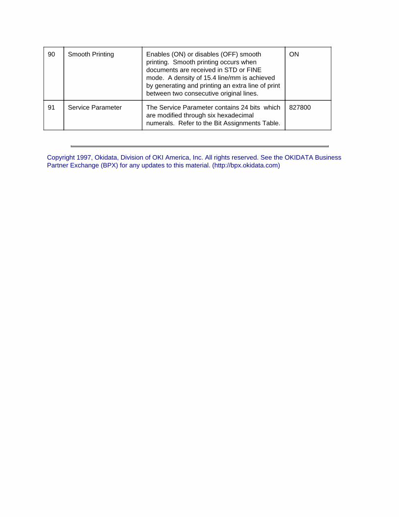
90 Smooth Printing Enables (ON) or disables (OFF) smooth printing. Smooth printing occurs when documents are received in STD or FINE mode. A density of 15.4 line/mm is achieved by generating and printing an extra line of print between two consecutive original lines.
ON
91 Service Parameter The Service Parameter contains 24 bits which are modified through six hexadecimal numerals. Refer to the Bit Assignments Table.
827800
Copyright 1997, Okidata, Division of OKI America, Inc. All rights reserved. See the OKIDATA Business Partner Exchange (BPX) for any updates to this material. (http://bpx.okidata.com)

Page: 109
Service Guide OF2200/2400/2600Chapter 2 Failure Analysis
2.9.02 Service Bit / Service Parameter
Okifax 2200 (Technical Function 27)
General InformationThe Service Bit enables or disables the following functions.
1. Drum Counter Display
2. Fuser Counter Display
3. Toner Counter Display
4. Service Default Report
5. Protocol Dump
6. Ring Response Time
7. Dial Parameters
8. Clearing the Printer Counters
Procedure
1. Press SELECT FUNCTION.
2. Press COPY twice.
3. Press LEFT ARROW.
4. Enter "2" from the numeric keypad.
5. Press LEFT ARROW.
6. Follow the appropriate steps for the unit you are working on.
7. Enter "27" from the numeric keypad.
The following message will be displayed.
27: SERVICE BIT?[ X } YES ( ¬ ) NO ( ® )X = ON or OFF.
8. Press RIGHT ARROW until ON appears.

9. Press LEFT ARROW to store the selected setting and display the next function.
10. Press SELECT FUNCTION to exit.
Okifax 2400/2600 (Technical Function 91)
General InformationThe Service Parameter is comprised of 24 bits.
Each bit controls one function. Each function has two states (1 or 0).
Groups of four bits are controlled by one hexadecimal number.
The Service Parameter enables or disables the following functions.
1. Drum Counter Display
2. Fuser Counter Display
3. Toner Counter Display
4. Service Default Report
5. Protocol Dump
6. Ring Response Time
7. Dial Parameters
8. Clearing the Printer Counters
Procedure
1. Refer to the Bit Assignments Table.
2. Select the bit(s) to be changed.
3. Determine the desired state (1 or 0) of the bit(s) being changed.
4. Add the values of the four bits of each hexadecimal numeral.
This number is the decimal equivalent of the desired hexadecimal numeral.
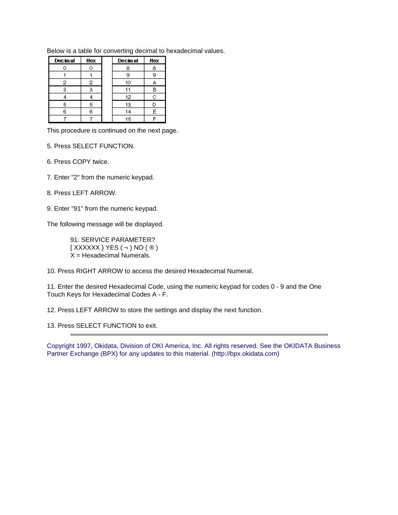
Below is a table for converting decimal to hexadecimal values.
This procedure is continued on the next page.
5. Press SELECT FUNCTION.
6. Press COPY twice.
7. Enter "2" from the numeric keypad.
8. Press LEFT ARROW.
9. Enter "91" from the numeric keypad.
The following message will be displayed.
91: SERVICE PARAMETER?[ XXXXXX } YES ( ¬ ) NO ( ® )X = Hexadecimal Numerals.
10. Press RIGHT ARROW to access the desired Hexadecimal Numeral.
11. Enter the desired Hexadecimal Code, using the numeric keypad for codes 0 - 9 and the One Touch Keys for Hexadecimal Codes A - F.
12. Press LEFT ARROW to store the settings and display the next function.
13. Press SELECT FUNCTION to exit.
Copyright 1997, Okidata, Division of OKI America, Inc. All rights reserved. See the OKIDATA Business Partner Exchange (BPX) for any updates to this material. (http://bpx.okidata.com)
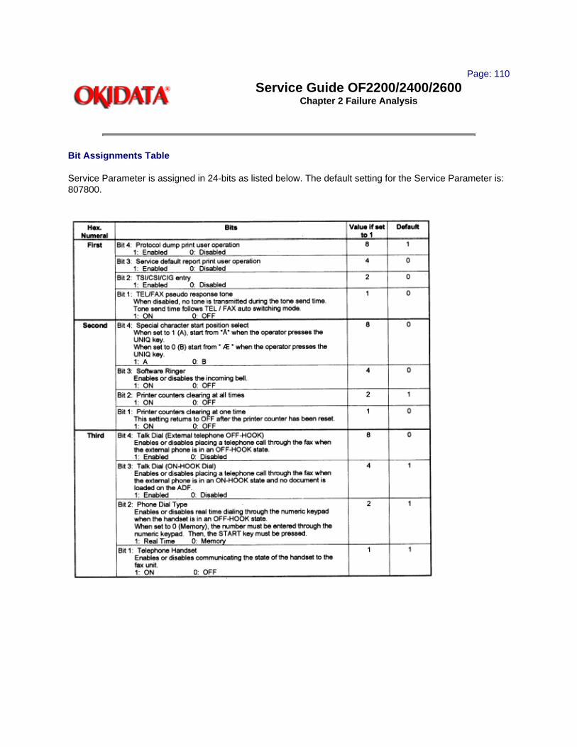
Page: 110
Service Guide OF2200/2400/2600Chapter 2 Failure Analysis
Bit Assignments Table
Service Parameter is assigned in 24-bits as listed below. The default setting for the Service Parameter is: 807800.

Copyright 1997, Okidata, Division of OKI America, Inc. All rights reserved. See the OKIDATA Business Partner Exchange (BPX) for any updates to this material. (http://bpx.okidata.com)

Page: 111
Service Guide OF2200/2400/2600Chapter 2 Failure Analysis
2.10 TEL / FAX AUTOMATIC SWITCHING
2.10.01 General InformationThe unit can automatically distinguish between voice and fax telephone calls. If the incoming call is a voice call, the unit will play a message asking the caller to wait while it rings to tell the user to pick up the handset. If the user does not answer, the unit automatically switches back to the facsimile mode to allow the calling party to manually send a fax. The TEL / FAX Timer function controls how long the unit waits before switching back to facsimile mode to receive a manually-sent fax. When the TEL / FAX Timer function is set to OFF, the unit will not switch back to facsimile reception mode.
Refer to the Users Guide for further information.
Copyright 1997, Okidata, Division of OKI America, Inc. All rights reserved. See the OKIDATA Business Partner Exchange (BPX) for any updates to this material. (http://bpx.okidata.com)

Page: 112
Service Guide OF2200/2400/2600Chapter 2 Failure Analysis
2.11 TOUCH TONE MODE
2.11.01 General InformationThis mode allows the unit to be controlled from a remote location through a touch-tone keypad (telephone or fax unit).
Refer to the Users Guide for further information.
Copyright 1997, Okidata, Division of OKI America, Inc. All rights reserved. See the OKIDATA Business Partner Exchange (BPX) for any updates to this material. (http://bpx.okidata.com)

Page: 113
Service Guide OF2200/2400/2600Chapter 2 Failure Analysis
2.12 DIALING PARAMETERS
2.12.01 General Information
There are four ways of dialing a number through the fax unit.
1. Numeric Keypad
2. External Telephone
3. One Touch Keys
4. Auto Dial Keys
The One Touch and Auto Dial Keys allow the operator to program numbers into the fax machines.
Refer to the Users Guide for further information.
Copyright 1997, Okidata, Division of OKI America, Inc. All rights reserved. See the OKIDATA Business Partner Exchange (BPX) for any updates to this material. (http://bpx.okidata.com)

Page: 114
Service Guide OF2200/2400/2600Chapter 2 Failure Analysis
2.13 USER FUNCTIONS
2.13.01 General Information
There are 25 programmable User Functions in the Okifax 2200.
There are 83 programmable User Functions in the Okifax 2400/2600.
The operator can program / set these functions to customize the operation of the unit.
Refer to the Users Guide for further information.
Copyright 1997, Okidata, Division of OKI America, Inc. All rights reserved. See the OKIDATA Business Partner Exchange (BPX) for any updates to this material. (http://bpx.okidata.com)

Page: 115
Service Guide OF2200/2400/2600Chapter 2 Failure Analysis
2.13.02 Dual Access Combination Table - Okifax 2400/2600
NOTE:Dual Access is available ONLY with the Okifax 2400 and Okifax 2600 units.

O Available
X Not Available
\ Not Applicable
D Available with some limitations
Priority of copy set in user/service settings
ON: Copy priority. No auto receive. Equivalent of X.
OFF: Receive priority. Copy interrupted and transition made to auto receive. In this case, copy operation does not automatically resume after completion of receive operation.
¨ Available with some limitations
Printing operation interrupted at end of the page and memory TX scanning is prioritized. After the completion of memory TX scanning, printing resumes.
Copyright 1997, Okidata, Division of OKI America, Inc. All rights reserved. See the OKIDATA Business Partner Exchange (BPX) for any updates to this material. (http://bpx.okidata.com)

Page: 116
Service Guide OF2200/2400/2600Chapter 2 Failure Analysis
Load from ventura if possible...
2.14 GENERAL OPERATION DIAGRAMS
2.14.01 General Information
The following pages are a graphical representation of the access path for the various functions of the facsimile unit.
For detailed information on each function, refer to the appropriate Users Documentation or section of this Service Handbook.
Okifax 2200
When the unit is in standby mode, two options are available.
1. A document is loaded into the ADF.
2. No document is loaded.
If a document is loaded, go to DOCUMENT LOADED for the available options.
If a document is not loaded, press SELECT FUNCTION.From this point, three options are available.
3. Printout of message in memory (if present).
4. Confidential message printout (if present).
5. Polling Reception
From this point, four options are available.
Press LEFT ARROW.
Press RIGHT ARROW.
Press AUTO DIAL.
Press COPY twice.
Pressing the LEFT ARROW or AUTO DIAL leads you to a single feature (Password or Auto Dial numbers.
Pressing RIGHT ARROW (once) or COPY (twice) leads you to several features.
Document Loaded
Document Loading Date & Time / Select Location Broadcast / (Memory TX) Long Document TX Delayed Memory TX Select Group Delayed TX Confidential TX Relay Broadcast Initiate - TX Polling RX
Document Not Loaded
Document Not Loaded
Press SELECT FUNCTION.
Printout of MSG in Memory (if present)
Confidential MSG Printout (if present)
Polling RX
Press LEFT ARROW
Password is OK
Press AUTO DIAL
Enter the two digit number (01 - 70) to access each Auto Dial Setting.
Press copy twice.
Technical Program [Access by pressing and holding COPY during Power ON]
Press LEFT ARROW to enter the Technical Program.
Press 1, 2, or 3 to access the Local Test, Technical Functions, or System Reset.
1. Local Test
Press LEFT ARROW to access tests.
Then, enter the test number.
1. Self Diagnosis
2. Scan Operation
3. LED Test
4. Tone Send Test
5. Modem Send Test
6. Modem Rec Test
7. MF (Tone) Send Test
8. P.Unit Print Test

9. Voice Msg Send Test
2. Technical Function
Press LEFT ARROW to access functions.
Then, enter the function number. Refer to Module 2.9.
3. System Reset
Press LEFT ARROW to access resets.
Then, enter the reset number.
1. All Data Clear
2. Location Data Clear
3. Config Data Clear
4. TX Pages Clear
5. RX Pages Clear
Press RIGHT ARROW
Press LEFT ARROW to access Report Printout. Press RIGHT ARROW to access User Program.
Report Printout
Press LEFT ARROW to access reports.
Then, enter the report number.
1. Activity Report
2. Broadcast MCF
3. Multi-Polling MCF
4. Phone Directory
5. Configuration
6. Print Counter DSP
7. Drum Counter DSP ** Service Bit set ON **
8. Fuser Counter DSP ** Service Bit set ON **
9. Toner Counter DSP ** Service Bit set ON **
0. Service Default ** Service Bit set ON **

*. Protocol Dump ** Service Bit set ON **
User Program [Access by pressing and holding SELECT FUNCTION during Power ON)
Press LEFT ARROW to access programs.
Then, enter the program number.
1. One Touch Key Prg
2. Two Digit Auto Dial Prg
3. Group Setting
4. Function Program
Press LEFT ARROW to access programs.
Then, enter the program number (01 - 25). Refer to User's Functions in the User's Guide.
5. Data Programming
Press LEFT ARROW to access programs.
Then, enter the program number.
1. Clock Adjustment
2. System Data Program
Press RIGHT ARROW to access features.
Then, press ARROW to reach the desired feature.
TSI /CSI
Sender ID
CBM Phone No.
3. Dial Parameter
Press RIGHT ARROW to access features.
Then, press LEFT ARROW to reach the desired feature.
PTT Parameter ** Service Bit set ON **
Redial Tries ** Service Bit set ON **
Redial Interval ** Service Bit set ON **
Busy Tone Detect ** Service Bit set ON **

MF (TONE) or DP (Pulse)
Pulse Dial Rate ** Service Bit set ON **
Pulse Make Ratio ** Service Bit set ON **
Pulse Dial Type ** Service Bit set ON **
MF (Tone) Duration ** Service Bit set ON **
PBX Line ** Service Bit set ON **
Access Digit
Flash / Earth / Normal ** Service Bit set ON **
Dial Tone Detect ** Service Bit set ON **
Auto Start
6. Program Password
Press LEFT ARROW to access.
Mail Box No. / Mail Box Password
7. Department ID Prg
Press LEFT ARROW to access.
Restrict Access
Restrict No.
8. Printer Counter Clear ** Service Bit set ON **
Press LEFT ARROW to access programs.
Then, enter the program number.
1. Toner Counter
2. Drum Counter
3. Fuser Counter
4. Print Counter

Copyright 1997, Okidata, Division of OKI America, Inc. All rights reserved. See the OKIDATA Business Partner Exchange (BPX) for any updates to this material. (http://bpx.okidata.com)
Page: 117
Service Guide OF2200/2400/2600Chapter 3 Disassembly & Maintenance
3.1 MAINTENANCE
3.1.01 General InformationThis section lists the parts replacement, adjustment, cleaning, and lubrication procedures.Disassembly should not be performed unless absolutely necessary. NEVER perform disassembly on a malfunctioning unit until you have followed the failure analysis procedures in Module Two of this Service Handbook.
Follow the procedures listed in Adjustments and Service Settings . Counters may have to be reset and adjustments may be required when either consumables or parts are replaced. Failure to perform these procedures could result in unnecessary service calls.
The facsimile unit is a xerographic device. Cleaning procedures must be performed correctly if high print quality is to be achieved.
3.1.02 Maintenance ToolsThe following tools are required to service the unit.
· #2 Phillips tip screwdriver (with magnetic tip)
· Straight-slot screwdriver
· Needle nose pliers (4 inch)
· Diagonal Cutters
· Digital multimeter
· Shop vacuum with toner filter
· Soft, lint-free cloth
· All-purpose cleaner
· Dow Corning Molycoat BR-2 or Molycoat EM-300L or equivalent
3.1.03 Maintenance Precautions
· Do not disassemble the unit if it is operating normally.
· Before starting disassembly or assembly, always power OFF the unit and detach the AC power cord.
· Detach all telephone lines, if installed.
· Do not remove parts unnecessarily: try to keep disassembly to a minimum.
· Use the recommended maintenance tools.
· When disassembling, follow the listed sequence. Failure to follow

the correct sequence may result in damaged parts.
· Since screws, collars, and other small parts are easily lost, they should be temporarily attached to the original positions.
· When handling circuit boards, use extreme care. Integrated circuits (microprocessors, ROM, and RAM) can be destroyed by static electricity.
· Do not place printed circuit boards directly on conductive surfaces.
· Follow the recommended procedures when replacing assemblies or units.
Copyright 1997, Okidata, Division of OKI America, Inc. All rights reserved. See the OKIDATA Business Partner Exchange (BPX) for any updates to this material. (http://bpx.okidata.com)

Page: 118
Service Guide OF2200/2400/2600Chapter 3 Disassembly & Maintenance
3.2 DISASSEMBLY/ASSEMBLY PROCEDURES
General InformationThis section contains the disassembly procedures. Only the removal procedures are explained here. Reverse the procedure for the installation.
This Service Handbook lists the disassembly procedures for major components of the unit. Be sure to read all notes, cautions, and warnings, as they contain important information regarding disassembly / assembly.
Copyright 1997, Okidata, Division of OKI America, Inc. All rights reserved. See the OKIDATA Business Partner Exchange (BPX) for any updates to this material. (http://bpx.okidata.com)

Page: 119
Service Guide OF2200/2400/2600Chapter 3 Disassembly & Maintenance
3.2.01 Preliminary Items
1. Press the AC switch and power OFF the unit.
2. Detach the AC power cord.
3. Detach the modular telephone cord.
4. Remove the handset cord (1) and handset (2).
5. Remove the document stacker tray (3).
6. Remove the paper cassette assembly (4).
7. Raise the document table (5).
8. Press the buttons and raise the copy stacker (6).
9. Remove the image drum with toner cartridge.
NOTES:
Refer to Module 3.4 of this Service Handbook for cleaning details.
Refer to Module 2.8 of this Service Handbook for Toner and Drum Counter Information.
P/N 53549709 Handset RSPL B.2.01
P/N 56628101 Cord: Handset RSPL B.2.01
P/N 56116901 Kit: Image Drum Consumable B.2.05 , B.2.20
P/N 52106701 Kit: Toner Cartridge Consumable B.2.05 , B.220
P/N 56618901 Cord: AC Power RSPL B.2.01 , B.2.17
P/N 56621001 Cord: Modular Telephone RSPL B.2.01 , B.2.17
P/N 50218501 Cassette: Universal (Assembly) RSPL B.2.01
Includes the items listed below.
N/A Cassette: Universal
N/A Guide: Universal (R)
N/A Guide: Universal (L)
N/A Rack

N/A Pinion
N/A Plate: Sheet
P/N 51113110 Cork: Friction
N/A Guide: Universal (T)
P/N 70026101 Tray: Legal/Universal Paper Option B.2.18 (100 Sheet Capacity)
P/N 50105501 Stacker: Universal (Assembly) RSPL B.2.01 Includes the items listed below.
P/N N/A Stacker: Universal
P/N N/A Sub: Stacker
Copyright 1997, Okidata, Division of OKI America, Inc. All rights reserved. See the OKIDATA Business Partner Exchange (BPX) for any updates to this material. (http://bpx.okidata.com)

Page: 120
Service Guide OF2200/2400/2600Chapter 3 Disassembly & Maintenance
3.2.02 Document Stay Guide and Assembly; Rear and Terminal Cap Covers
1. Open the document guide assembly.
2. Remove the two screws from the document guide stay.
3. Remove the document guide stay.
4. Spread one end of the document guide assembly outward until it clears the scanner hinge, pivot the other end up and out, then remove the document guide assembly.
NOTE:The document guide assembly includes the left and right document guides, document table guide, and the document guide cover, pinion gear. To replace any of these parts, order the assembly.
5. Remove the two screws that retain the rear cover.
6. Remove the rear cover and the terminal cap cover.
7. Remove the screw, then remove the terminal cap cover from the rear cover.
P/N N/A Plate: Model Name 2200 B.2.01
P/N N/A Plate: Model Name 2400 B.2.01
P/N N/A Plate: Model Name 2600 B.2.01
P/N N/A Screw B.2.10
P/N 50806201 Stay: Document Guide RSPL B.2.10
P/N 53070206 Cover: Terminal Cap RSPL B.2.01
P/N 53071501 Cover: Rear RSPL B.2.01
P/N 51013401 Document: Guide Assembly RSPL B.2.01 Includes the items listed below.
P/N N/A Guide: Document (L)
P/N N/A Guide: Document (R)
P/N N/A Cover: Document Guide
P/N N/APinion
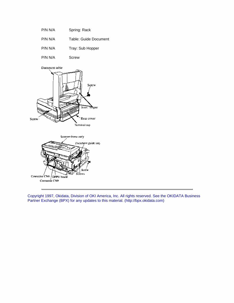
P/N N/A Spring: Rack
P/N N/A Table: Guide Document
P/N N/A Tray: Sub Hopper
P/N N/A Screw
Copyright 1997, Okidata, Division of OKI America, Inc. All rights reserved. See the OKIDATA Business Partner Exchange (BPX) for any updates to this material. (http://bpx.okidata.com)

Page: 121
Service Guide OF2200/2400/2600Chapter 3 Disassembly & Maintenance
3.2.03 Right Side Cover and Speaker
CAUTIONDo NOT attempt to remove the right side cover until all memory cards have been removed.If the right side cover is removed too quickly, the speaker wires could be damaged.To completely remove the right side cover, you must also remove the speaker.
1. Perform procedure 3.2.02 .
2. Raise the document guide table.
3. Remove the IC card cover by lifting up, then out.
4. Remove the two screws, using a small flat screw driver detach the right side cover assembly by lifting up, then out.
5. Disconnect the speaker connector CN3 on the main control board.
6. Remove the screw, and remove the bracket and the speaker.
NOTE:The speaker harness goes to connector CN3 of the main control board.
P/N 51709701 Bracket: Speaker B.2.02
P/N 53071211 Cover: Side (Right) 2200/2400 RSPL B.2.02
P/N 53071201 Cover: Side (Right) 2600 RSPL B.2.02
P/N 53071801 Cover: IC Card RSPL B.2.02
P/N 57001401 Speaker RSPL B.2.02 ,B.2.17

Copyright 1997, Okidata, Division of OKI America, Inc. All rights reserved. See the OKIDATA Business Partner Exchange (BPX) for any updates to this material. (http://bpx.okidata.com)

Page: 122
Service Guide OF2200/2400/2600Chapter 3 Disassembly & Maintenance
3.2.04 Network Control Unit
1. Perform procedure 3.2.02.
2. Detach the fan connector from the printer control board.
3. Remove the two screws.
4. Remove the network control unit by pulling it toward you.
5. Disconnect the three connectors from the NCU-U board.
6. Remove the network control unit and package shelf.
P/N 50106701 Package: Shelf B.2.08
P/N 55073401 PCB: Line-JU RSPL B.2.08
P/N 55073501 PCB: NCU-U RSPL B.2.08
P/N N/A Screw B.2.08
Copyright 1997, Okidata, Division of OKI America, Inc. All rights reserved. See the OKIDATA Business Partner Exchange (BPX) for any updates to this material. (http://bpx.okidata.com)

Page: 123
Service Guide OF2200/2400/2600Chapter 3 Disassembly & Maintenance
3.2.05 Left Side Cover Assembly
1. Perform procedure 3.2.02.
2. Open the document stacker cover and the document table.
3. Detach the two pin connector cable from the main control board.
4. Slide the cables from the network control board towards the left side cover until the cables are free.
5. Remove the two screws, then detach the left side cover by lifting it up and outward.
6. Remove the left side cover and cradle assembly.
P/N 53071401 Cover: Side (Left) RSPL B.2.02
P/N 56630301 Cable: Hook Switch MT-25/DFCU B.2.17
Copyright 1997, Okidata, Division of OKI America, Inc. All rights reserved. See the OKIDATA Business Partner Exchange (BPX) for any updates to this material. (http://bpx.okidata.com)

Page: 124
Service Guide OF2200/2400/2600Chapter 3 Disassembly & Maintenance
3.2.06 Cradle Assembly
1. Perform the procedures
3.2.01.
3.2.02.
3.2.05.
2. Remove the two screws from the inner side of the left side cover.
3. Detach the cradle assembly from the three hooks and remove the cradle cover.
4. Remove the two screws on the underside of the cradle base.
5. Use a small flat screw driver and detach the three hooks.
6. Remove the cradle base.
P/N 50317201 Cover: Cradle RSPL B.2.02
P/N 53071401 Cover: Side (Left) RSPL B.2.02
P/N 53071601 Cover: Cradle Base RSPL B.2.02
Copyright 1997, Okidata, Division of OKI America, Inc. All rights reserved. See the OKIDATA Business Partner Exchange (BPX) for any updates to this material. (http://bpx.okidata.com)

Page: 125
Service Guide OF2200/2400/2600Chapter 3 Disassembly & Maintenance
3.2.07 Hook Switch Board
1. Perform procedures
3.2.01.
3.2.02.
3.2.05.
3.2.06.
2. Detach the cables and take out the modular jack.
3. Remove the two screws that retain the hook switch board.
4. Remove the hook switch board.
5. Detach the two connectors.
P/N 55074002 PCB: Hook Switch RSPL B.2.02
Copyright 1997, Okidata, Division of OKI America, Inc. All rights reserved. See the OKIDATA Business Partner Exchange (BPX) for any updates to this material. (http://bpx.okidata.com)

Page: 126
Service Guide OF2200/2400/2600Chapter 3 Disassembly & Maintenance
3.2.08 Memory Board
1. Perform procedures
3.2.02.
3.2.03.
3.2.08.
2. Remove the three screws (A) that retain the memory board bracket.
3. Detach the memory board with the memory board bracket from the connection board.
4. Remove the four mounting screws(B), then remove the memory board from the bracket.
P/N 51710401 Bracket: DFME B.2.10
P/N 55075201 PCB: ME 250 2200 RSPL B.2.10
P/N 55075402 PCB: DFME-2 2400 RSPL B.2.10
P/N 55075401 PCB: DFME 2600 RSPL B.2.10
Copyright 1997, Okidata, Division of OKI America, Inc. All rights reserved. See the OKIDATA Business Partner Exchange (BPX) for any updates to this material. (http://bpx.okidata.com)

Page: 127
Service Guide OF2200/2400/2600Chapter 3 Disassembly & Maintenance
3.2.09 Control Panel Assembly and Paper Guide (U)
1. Perform procedure 3.2.02.
2. Open the control panel assembly.
3. Remove the two screws that retain the ground cables.
4. Remove the two scanner hinges.
5. Detach the control panel cable from connector CN2 of the main control board.
6. Remove the paper guide (u) and the control panel assembly.
7. Remove the two screws on the underside of the control panel assembly and cut the tie wrap.
8. Release the two hooks and remove the control panel assembly.
NOTE:The longer scanner hinge is on the right side.
P/N 50806301 Hinge: Scanner (R) B.2.10
P/N 50806302 Hinge: Scanner (L) B.2.10
P/N 50105601 Panel: Control (Assembly) 2200 RSPL B.2.03
Includes all of the items listed below.
P/N N/A Cover: Expanded (B) 2200/2400 B.2.03 , 04
P/N N/A Label: Ten-Key 2200 B.2.03
P/N N/A Sheet: Function 2200 B.2.03
P/N 53072001 Sheet: One-Touch (U) 2200 RSPL B.2.03
P/N 51013601 Guide: Paper Upper RSPL B.2.16
P/N 53071901 Cover: One-Touch RSPL B.2.03 , 04
P/N 50105611 Panel: Control (Assembly) 2400 RSPL B.2.04
Includes all of the items listed below . P/N N/A Cover: Expanded (B) 2200/2400 B.2.03 , 04 P/N N/A Sheet: Function (1) 2400 B.2.04

P/N N/A Label: Ten-Key 2400/2600 B.2.04 P/N 51013601 Guide: Paper Upper RSPL B.2.16 P/N 53071901 Cover: One-Touch RSPL B.2.03 , 04 P/N 53072011 Sheet: One-Touch (U) 2400/2600 RSPL B.2.04 P/N 50105610 Panel: Control (Assembly) 2600 RSPL B.2.04
Includes all of the items listed below. P/N N/A Label: Ten-Key 2400/2600 B.2.04 P/N N/A Sheet: Function (1) 2600 B.2.04 P/N 51013601 Guide: Paper Upper RSPL B.2.16 P/N 53071901 Cover: One-Touch RSPL B.2.03 , 04 P/N 53072011 Sheet: One-Touch (U) 2400/2600 RSPL B.2.04 P/N 53072102 Cover: Expanded (A) 2600 B.2.04 P/N 53072201 Sheet: One-Touch (D) 2600 B.2.04
Copyright 1997, Okidata, Division of OKI America, Inc. All rights reserved. See the OKIDATA Business Partner Exchange (BPX) for any updates to this material. (http://bpx.okidata.com)

Page: 128
Service Guide OF2200/2400/2600Chapter 3 Disassembly & Maintenance
3.2.10 Feed (1) and Pinch Rollers; Tension Arm; ADF Spring and Back Up Plate
1. Perform procedure 3.2.09.
2. Remove the four screws.
3. Remove the two upper releases.
4. Remove the four screws from the support plate.
5. Use needle nose pliers to remove the spring.
6. Fold back the two adhesive static brushes.
7. Remove the support plate.
8. Remove the feed roller assembly.
9. Slide out the pinch roller from the support plate.
10. Remove the ADF spring, tension arm, and ADF back up plate.
NOTE:When cleaning, refer to Module 3.4 of this Service Handbook.
CAUTION:When performing this procedure, the static brushes must be replaced.
P/N 51113001 Shaft: Pinch Roller B.2.15
P/N 50926101 Spring: Sub Pinch RSPL B.2.15

P/N 50218701 Release: Upper RSPL B.2.15
P/N 50406201 Roller: Pinch B.2.15
P/N 50926001 Spring: ADF RSPL B.2.15
P/N 50926601 Spring: Upper Pinch (L) B.2.15
P/N 50926602 Spring: Upper Pinch (R) B.2.15
P/N 51304701 Brush: Static (A) B.2.15
P/N 51304801 Brush: Static (B) B.2.15
P/N 51710601 Bracket: Pinch Roller B.2.15
P/N 53061201 Arm: ADF Tension RSPL B.2.15
P/N 53339201 Plate: Support B.2.15
P/N 53339401 Plate: Earth (ADF) (L) B.2.15
P/N 53339402 Plate: Earth (ADF) B.2.15
P/N 53339801 Plate: ADF Back-Up RSPL B.2.15
P/N 50406801 Roller: Feed (Assembly) RSPL B.2.12
Includes the items listed below.
P/N N/A Bearing B.2.12
P/N N/A Roller: Feed (2) B.2.12
P/N N/A Gear: Z21 B.2.12
P/N N/A Washer: Compression B.2.12
P/N 50407601 Roller: Feed (Assembly) 1 RSPL B.2.15
Includes the items listed bel ow .
P/N N/A Roller: Feed (1) B.2.15
P/N N/A Bearing B.2.15
P/N N/A Gear: (Z30) B.2.15
P/N 50219201 Assembly: Sub and Pinch Roller Guide RSPL B.2.15
Includes the items listed below .
P/N N/A Guide: Sub Pinch Roller B.2.15
P/N N/A Roller: Sub Pinch B.2.15
Copyright 1997, Okidata, Division of OKI America, Inc. All rights reserved. See the OKIDATA Business Partner Exchange (BPX) for any updates to this material. (http://bpx.okidata.com)
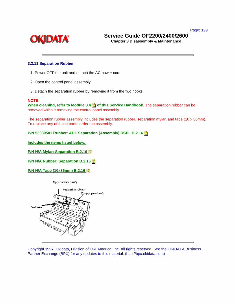
Page: 129
Service Guide OF2200/2400/2600Chapter 3 Disassembly & Maintenance
3.2.11 Separation Rubber
1. Power OFF the unit and detach the AC power cord.
2. Open the control panel assembly.
3. Detach the separation rubber by removing it from the two hooks.
NOTE:When cleaning, refer to Module 3.4 of this Service Handbook. The separation rubber can be removed without removing the control panel assembly.
The separation rubber assembly includes the separation rubber, separation mylar, and tape (10 x 36mm). To replace any of these parts, order the assembly.
P/N 53339501 Rubber: ADF Separation (Assembly) RSPL B.2.16
Includes the items listed below.
P/N N/A Mylar: Separation B.2.16
P/N N/A Rubber: Separation B.2.16
P/N N/A Tape (10x36mm) B.2.16
Copyright 1997, Okidata, Division of OKI America, Inc. All rights reserved. See the OKIDATA Business Partner Exchange (BPX) for any updates to this material. (http://bpx.okidata.com)

Page: 130
Service Guide OF2200/2400/2600Chapter 3 Disassembly & Maintenance
3.2.12 Cover (U)
1. Perform procedure 3.2.09.
2. Remove the two screws.
3. Remove the cover (U).
P/N 53071701 Cover: (U) RSPL B.2.10
Copyright 1997, Okidata, Division of OKI America, Inc. All rights reserved. See the OKIDATA Business Partner Exchange (BPX) for any updates to this material. (http://bpx.okidata.com)

Page: 131
Service Guide OF2200/2400/2600Chapter 3 Disassembly & Maintenance
3.2.13 ADF Roller, Sub Roller, and Sensor Roller; Paper Guide (M); Release Springs, and Release Levers
1. Perform procedure 3.2.12.
2. Remove the four screws.
3. Detach the two claws from the left side of the paper guide (M).
4. Remove the paper guide (M).
5. Remove the two screws, then remove the two release springs.
6. Detach the two release levers.
7. Remove the sensor roller assembly and the sub-roller assembly.
8. Detach the connector.
9. Remove the ADF roller.
NOTE:When cleaning, refer to Module 3.4 of this Service Handbook.
When lubricating, refer to Module 3.5 of this Service Handbook.
P/N 50806501 Tie: Wire (Goes on Paper Guide M) RSPL B.2.10
P/N 50926201 Spring: Release RSPL B.2.13

P/N 51013701 Guide: Paper (M) RSPL B.2.10
P/N N/A Cable: Ground B.2.10
P/N 50218801 Release: Lower RSPL B.2.13
P/N 50406701 Roller: Sub (Assembly) RSPL B.2.13
Includes all of the items listed below.
P/N N/A Bearing B.2.13
P/N N/A Roller: Sub B.2.13
P/N N/A Gear: A (Z20) B.2.13
P/N N/A Washer: Compression B.2.12
P/N 50407101 Roller: ADF Assembly RSPL B.2.13
Includes all of the items listed below .
P/N N/A Bearing B.2.13
P/N N/A Shaft: ADF B.2.13
P/N N/A Roller: ADF Feed B.2.13
P/N N/A Gear: (Z28) B.2.13
P/N N/A Clutch B.2.13
P/N N/A Washer: Compression B.2.12
P/N 50407201 Roller: Sensor Assembly RSPL B.2.13
Includes all of the items listed below.
P/N N/A Roller: Sensor B.2.13
P/N N/A Gear: Z21 B.2.13
P/N N/A Bearing B.2.13
P/N N/A Collar B.2.13
P/N N/A Washer: Compression B.2.12
P/N N/A Collar B.2.13
Copyright 1997, Okidata, Division of OKI America, Inc. All rights reserved. See the OKIDATA Business Partner Exchange (BPX) for any updates to this material. (http://bpx.okidata.com)

Page: 132
Service Guide OF2200/2400/2600Chapter 3 Disassembly & Maintenance
3.2.14 Verification Stamp, Paper Guide (E), and Feed Roller(2)
1. Perform procedure 3.2.13.
2. Remove the two screws.
3. Remove the paper guide (E).
4. Remove the verification stamp from the scanner frame.
5. Remove the feed roller (2)
NOTE:When cleaning, refer to Module 3.4 of this Service Handbook.
P/N 51013501 Guide: Paper (E) 2200/2400 RSPL B.2.10
P/N 51013502 Guide: Paper (E) 2600 RSPL B.2.10
P/N 50708301 Stamp: Verification 2400/2600 RSPL B.2.12 , 17
P/N 50708412 Ink: Verification Stamp 2400/2600 RSPL B.2.12
P/N 50707201 Pad: Verification Stamp 2400/2600 RSPL B.2.12
P/N 50406801 Roller: Feed (Assembly) RSPL B.2.12
Includes the items listed below.
P/N N/A Bearing B.2.12
P/N N/A Roller: Feed (2) B.2.12
P/N N/A Gear: Z21 B.2.12
P/N N/A Washer: Compression B.2.12

Copyright 1997, Okidata, Division of OKI America, Inc. All rights reserved. See the OKIDATA Business Partner Exchange (BPX) for any updates to this material. (http://bpx.okidata.com)

Page: 133
Service Guide OF2200/2400/2600Chapter 3 Disassembly & Maintenance
3.2.15 Contact Image Sensor Assembly
1. Perform procedure 3.2.14.
2. Detach the connector and remove the four screws.
3. Cut the tie wrap, then remove the contact image sensor assembly.
NOTE:When cleaning, refer to Module 3.4 of this Service Handbook .
P/N 50407502 Sensor: Image (B4) Assembly 2200/2400 RSPL B.2.14
Includes the items listed below.
P/N N/A Sensor: B4 2200/2400 B.2.14
P/N N/A Plate: Ground (SR) B.2.14
P/N N/A Holder: Sensor B.2.14
P/N N/A Plate: Ground (SL) B.2.14
P/N N/A Screw B.2.14
P/N 50407501 Sensor: Image (A3) (Assembly) 2600 RSPL B.2.14
Includes the items listed below.
P/N N/A Sensor: A3 2600 B.2.14
P/N N/A Plate: Ground (SR) B.2.14
P/N N/A Holder: Sensor B.2.14
P/N N/A Plate: Ground (SL) B.2.14
P/N N/A Screw B.2.14

Copyright 1997, Okidata, Division of OKI America, Inc. All rights reserved. See the OKIDATA Business Partner Exchange (BPX) for any updates to this material. (http://bpx.okidata.com)

Page: 134
Service Guide OF2200/2400/2600Chapter 3 Disassembly & Maintenance
3.2.16 Gear Frame Assembly and Scan Motor
1. Perform procedure 3.2.13.
2. Remove the three screws.
3. Remove the gear frame assembly.
4. Remove the two mounting screws.
5. Remove the cable from the scan motor, then detach the scan motor from the gear frame assembly.
NOTE:When lubricating, refer to Module 3.5 of this Service Handbook.
P/N 53345002 Frame: Gear Assembly 2200 RSPL B.2.14
Includes the items listed below.
P/N N/A Gear: Frame B.2.14
P/N N/A Gear (Z17/26) B.2.14
P/N N/A Gear: (Z45) B.2.14
P/N N/A Gear: Idle (Z30) B.2.14
P/N N/A Gear: (Z19/52) B.2.14
P/N 56511501 Motor: Scan 2200 RSPL B.2.14
P/N N/A Screw B.2.14
P/N N/A Screw B.2.14
P/N 53345001 Frame: Gear Assembly 2400/2600 RSPL B.2.14
Includes the items listed below.
P/N N/A Gear: Frame B.2.14
P/N N/A Gear (Z17/26) B.2.14
P/N N/A Gear: (Z45) B.2.14
P/N N/A Gear: Idle (Z30) B.2.14
P/N N/A Gear: (Z19/52) B.2.14
P/N 56511401 Motor: Scan 2400/2600 RSPL B.2.14
P/N N/A Screw B.2.14

P/N N/A Screw B.2.14
Copyright 1997, Okidata, Division of OKI America, Inc. All rights reserved. See the OKIDATA Business Partner Exchange (BPX) for any updates to this material. (http://bpx.okidata.com)

Page: 135
Service Guide OF2200/2400/2600Chapter 3 Disassembly & Maintenance
3.2.17 PC-1, PC-2, and Pinch Roller
NOTE:There are two PC-1 sensors (Doc. Detect & B4 Size) on the OF 2200/2400.
There are three PC-1 sensors (Doc. Detect & B4 Size & A3 Size) on the OF 2600.
All three products contain one PC-2 sensor (Read Station).
Each sensor has one hook and one connector.
1. Perform this procedure: 3.2.13.
2. Disconnect the three connectors on the 2200 and 2400 units, the OF 2600 has four connectors.
3. Using a straight-slot screwdriver, open the sensor latches
4. Remove the PC1 sensors and the PC2 sensor.
5. Push the two pinch springs and slide out the pinch roller shaft.
6. Remove the pinch roller.
P/N 50407301 Sensor: PC1/B4/A3 (Assembly) RSPL B.2.13
Includes the items listed below .
P/N N/A Bracket: PC B.2.13
P/N N/A Sensor: Photo B.2.13
P/N N/A Lever: PC1 B.2.13
P/N 50407401 Sensor: PC2 (Assembly) RSPL B.2.13
Includes the items listed below.
P/N N/A Bracket: PC B.2.13
P/N N/A Lever: PC2 B.2.13
P/N N/A Sensor: Photo B.2.13

Copyright 1997, Okidata, Division of OKI America, Inc. All rights reserved. See the OKIDATA Business Partner Exchange (BPX) for any updates to this material. (http://bpx.okidata.com)

Page: 136
Service Guide OF2200/2400/2600Chapter 3 Disassembly & Maintenance
3.2.18 Release Guide Assembly and Sub-Cover (Right)
1. Perform procedures
3.2.05
3.2.08
3.2.09
2. Detach the release guide assembly from the left and right scanner base.
3. Remove the release guide spring and the release guide assembly.
4. Open the stacker cover and release the inner cover.
5. Remove the four screws and detach the right sub-cover.
P/N 53069701 Cover: Inner RSPL B.2.05
P/N 53071301 Cover: Sub (R) RSPL B.2.09
P/N 50927701 Spring: Release Guide (R) RSPL B.2.10
P/N 52202801 Mylar: Exit Strip (Guide Rel Assy)RSPL B.2.10
P/N 51012801 Guide: Release Assembly RSPL B.2.10
Includes the items listed below.
P/N N/A Bias: Spring B.2.10
P/N N/A Guide: Release B.2.10
P/N N/A Roller: Eject B.2.10

Copyright 1997, Okidata, Division of OKI America, Inc. All rights reserved. See the OKIDATA Business Partner Exchange (BPX) for any updates to this material. (http://bpx.okidata.com)

Page: 137
Service Guide OF2200/2400/2600Chapter 3 Disassembly & Maintenance
3.2.19 Main Control Board, Second Tray Interface Board
1. Perform procedures
3.2.03
3.2.08
2. Remove the three screws (A).
3. Lift the main control board, and remove the connectors.
4. Remove the main control board.
5. Disconnect the connector.
6. Remove the screw (B), then remove the second tray interface board.
P/N 55076001 PCB: MT-25 2200 B.2.11
P/N 55076102 PCB: DFCU/MCNT-350 2400/2600 B.2.11
P/N 55073901 PCB: Second Tray Interface RSPL B.2.11
P/N 55075901 PCB: CB -250 2200 B.2.11
P/N 55076202 PCB: CB -350 2400/2600 B.2.11
P/N 51710701 Edge Saddle B.2.11
P/N N/A Screw B.2.11
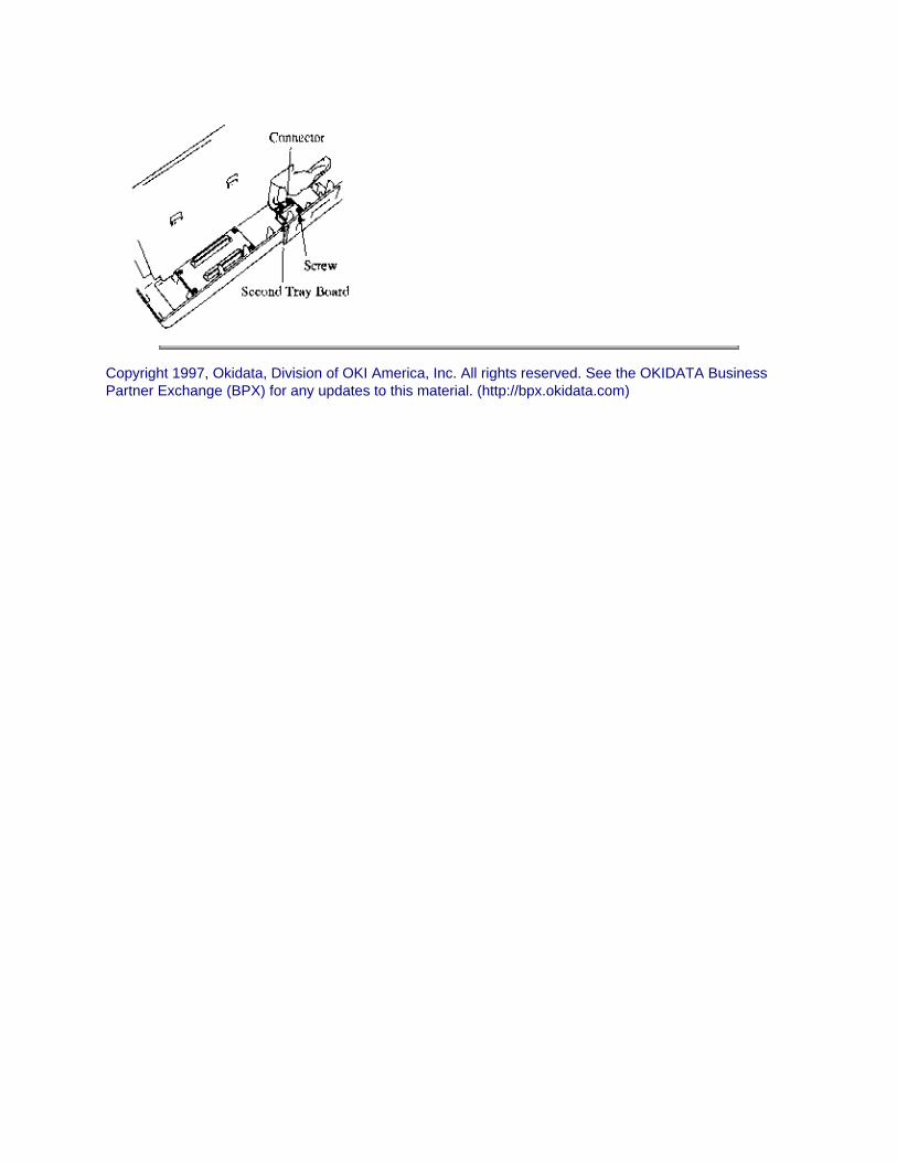
Copyright 1997, Okidata, Division of OKI America, Inc. All rights reserved. See the OKIDATA Business Partner Exchange (BPX) for any updates to this material. (http://bpx.okidata.com)
Page: 138
Service Guide OF2200/2400/2600Chapter 3 Disassembly & Maintenance
3.2.20 Lower Base Assembly
1. Perform procedures
3.2.02
3.2.03
3.2.05
3.2.18
2. Open the stacker cover.
3. Disconnect the two stepper motor connectors CN1, CN2, and the LED head cable from connector CN3 of the printer control board.
4. Remove the seven screws.
5. Remove the lower base.
P/N N/A Screw B.2.05
P/N N/A Screw B.2.05
P/N N/A Screw B.2.05
P/N 50217601 Frame: Lower Base Assembly RSPL B.2.05
Includes the items listed below .
P/N 53344501 Plate: Transfer Contact B.2.05
P/N 53344301 Plate: Ground (RE) B.2.05
P/N 53344401 Plate: Ground (BU) B.2.05

Copyright 1997, Okidata, Division of OKI America, Inc. All rights reserved. See the OKIDATA Business Partner Exchange (BPX) for any updates to this material. (http://bpx.okidata.com)

Page: 139
Service Guide OF2200/2400/2600Chapter 3 Disassembly & Maintenance
3.2.21 Stacker Cover and LED Head
1. Perform procedures
3.2.03
3.2.05
3.2.19 (except when removing LED Head).
2. Open the copy stacker, by pushing the buttons.
3. Disconnect the flat cable from the PC connector.
4. Remove the LED head while spreading the retainer on the copy stacker.
5. Press inward on the two hooks until the copy stacker is free from the two reset levers.
6. Spread the copy stacker until its free from the lower base, then remove the copy stacker.
NOTES:Be sure not to touch the lens portion of the LED head.
Under normal circumstances, the PC connector should NOT be removed from the LED head. If it is removed, use caution NOT to lose the connector pins.
When the LED head is replaced, the LED Head Drive Time may need to be set. Refer to Module 3.3 of this Service Handbook.
When cleaning, refer to Module 3.4 of this Service Handbook.
P/N N/A Cover: Stacker B.2.05
P/N 53069002 Cover: Face Down Stacker (Assembly) RSPL B.2.05
P/N 50104801 Tray: Stacker Cover Extension RSPL B.2.05
P/N 51013801 Guide: Wire RSPL B.2.05
P/N 56111202 LED Head Assembly RSPL B.2.05
Includes the items listed below.
P/N 51014601 Contact: Ground Clip RSPL B.2.05
P/N 56730201 Connector: PC RSPL B.2.05
P/N 56629102 Cable: LED Head RSPL B.2.05

Copyright 1997, Okidata, Division of OKI America, Inc. All rights reserved. See the OKIDATA Business Partner Exchange (BPX) for any updates to this material. (http://bpx.okidata.com)
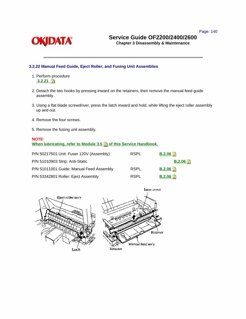
Page: 140
Service Guide OF2200/2400/2600Chapter 3 Disassembly & Maintenance
3.2.22 Manual Feed Guide, Eject Roller, and Fusing Unit Assemblies
1. Perform procedure 3.2.21
2. Detach the two hooks by pressing inward on the retainers, then remove the manual feed guide assembly.
3. Using a flat blade screwdriver, press the latch inward and hold, while lifting the eject roller assembly up and out.
4. Remove the four screws.
5. Remove the fusing unit assembly.
NOTE:When lubricating, refer to Module 3.5 of this Service Handbook.
P/N 50217501 Unit: Fuser 120V (Assembly) RSPL B.2.06
P/N 51010903 Strip: Anti-Static B.2.06
P/N 51011001 Guide: Manual Feed Assembly RSPL B.2.06
P/N 53342801 Roller: Eject Assembly RSPL B.2.06

Copyright 1997, Okidata, Division of OKI America, Inc. All rights reserved. See the OKIDATA Business Partner Exchange (BPX) for any updates to this material. (http://bpx.okidata.com)
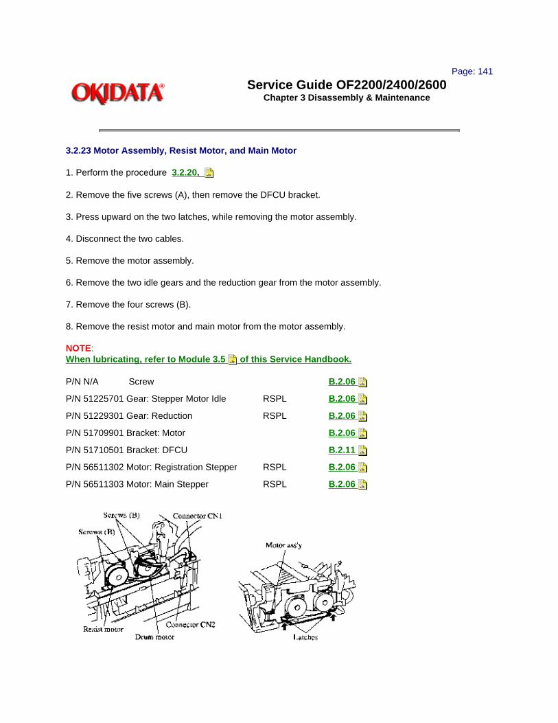
Page: 141
Service Guide OF2200/2400/2600Chapter 3 Disassembly & Maintenance
3.2.23 Motor Assembly, Resist Motor, and Main Motor
1. Perform the procedure 3.2.20.
2. Remove the five screws (A), then remove the DFCU bracket.
3. Press upward on the two latches, while removing the motor assembly.
4. Disconnect the two cables.
5. Remove the motor assembly.
6. Remove the two idle gears and the reduction gear from the motor assembly.
7. Remove the four screws (B).
8. Remove the resist motor and main motor from the motor assembly.
NOTE:When lubricating, refer to Module 3.5 of this Service Handbook.
P/N N/A Screw B.2.06
P/N 51225701 Gear: Stepper Motor Idle RSPL B.2.06
P/N 51229301 Gear: Reduction RSPL B.2.06
P/N 51709901 Bracket: Motor B.2.06
P/N 51710501 Bracket: DFCU B.2.11
P/N 56511302 Motor: Registration Stepper RSPL B.2.06
P/N 56511303 Motor: Main Stepper RSPL B.2.06

Copyright 1997, Okidata, Division of OKI America, Inc. All rights reserved. See the OKIDATA Business Partner Exchange (BPX) for any updates to this material. (http://bpx.okidata.com)

Page: 142
Service Guide OF2200/2400/2600Chapter 3 Disassembly & Maintenance
3.2.24 Pressure Roller, Transfer Roller and Gear, Idle Gears, Cover Open Arm, and Reset Levers
CAUTION:Do NOT touch the transfer roller! Touching the transfer roller may cause incomplete toner transfer, resulting in faded output.
1. Perform procedure 3.2.23.
2. Press down and hold the pressure roller, while removing the left reset lever and the right reset lever, remove the spring and cover open arm with the left reset lever.
3. Lift the pressure roller and remove it with the two springs and bushings.
4. Remove the eject roller gear.
5. Detach the hook on the gear side of the printer unit.
6. Lift the transfer roller from the gear side of the printer unit. Then, carefully remove the transfer roller and transfer roller gear.
NOTE:LubricationLightly lubricate the channels of the reset levers, as necessary. Refer to Module 3.5 of this Service
Handbook for lubrication details.
P/N 50406901 Roller: Pressure RSPL B.2.07
P/N 50805801 Lever: Reset (Left) RSPL B.2.07
P/N 50805901 Lever: Reset (Right) RSPL B.2.07
P/N 50924201 Spring: Stacker Cover Reset RSPL B.2.07
P/N 50926401 Spring: Pressure Roller Bias B.2.07
P/N 51229001 Gear: Transfer Roller RSPL B.2.07
P/N 51229101 Gear: Fuser Roller Idle RSPL B.2.07
P/N 51229201 Gear: Eject Roller Idle RSPL B.2.07
P/N 51607402 Bearing RSPL B.2.06 , 07
P/N 51607601 Bushing: Pressure Roller RSPL B.2.07
P/N 53068901 Arm: Cover Open RSPL B.2.07
P/N 53342601 Roller: Transfer RSPL B.2.07

Copyright 1997, Okidata, Division of OKI America, Inc. All rights reserved. See the OKIDATA Business Partner Exchange (BPX) for any updates to this material. (http://bpx.okidata.com)

Page: 143
Service Guide OF2200/2400/2600Chapter 3 Disassembly & Maintenance
3.2.25 Registration Roller, Sensor Plates, Damper Cover Arm and Gear
1. Perform procedures
3.2.20,
3.2.24.
2. Detach the one-way clutch gear.
3. Remove the resist roller.
4. Detach the one-way clutch gear and bearing.
5. Remove the hopping roller.
6. Each sensor plate has two hooks. Release the hooks and remove the toner sensor plate, the three inlet sensor plates, and the outlet sensor plate.
7. Remove the mounting screw, then remove the damper arm. Detach the damper gear.
8. Remove the two idle gears.
CAUTION:When lubricating, refer to Module 3.5 of this Service Handbook.Do NOT lubricate the sensor plates.
P/N 50219601 Assembly: Hopping Roller 2200 RSPL B.2.06
Includes the items listed below .
P/N N/A Shaft: Hopping Roller B.2.06
P/N N/A Rubber: Hopping Roller B.2.06
P/N 50405501 Sensor: Toner RSPL B.2.06
P/N 50407001 Roller: Registration (F) RSPL B.2.06
P/N 51010701 Plate: Sensor (Inlet) RSPL B.2.06
P/N 51010801 Plate: Sensor (Outlet) RSPL B.2.06
P/N 51011401 Plate: Paper Supply Sensor RSPL B.2.09
P/N 51011501 Plate: Cassette Sensor RSPL B.2.09
P/N 51228901 Gear: Hopping Roller Clutch RSPL B.2.06
P/N 51229401 Gear: Stacker Cover Damper RSPL B.2.06

P/N 51607402 Bearing RSPL B.2.06 , 07
P/N 51607501 Bearing: Registration Roller B.2.06
P/N 53069101 Arm: Stacker Cover Damper RSPL B.2.06
Copyright 1997, Okidata, Division of OKI America, Inc. All rights reserved. See the OKIDATA Business Partner Exchange (BPX) for any updates to this material. (http://bpx.okidata.com)

Page: 144
Service Guide OF2200/2400/2600Chapter 3 Disassembly & Maintenance
3.2.26 Line Board and Network Control Board
1. Perform procedures
3.2.02
3.2.04
2. Remove the connector.
3. Remove the three screws(A) and the ground cable.
4. Remove the line board.
5. Remove the connectors and the four screws (B), then remove the network control board from the package shelf.
NOTE:When lubricating, refer to Module 3.5 of this Service Handbook.
P/N 55073401 PCB: Line-JU RSPL B.2.08
P/N 55073501 PCB: NCU-U RSPL B.2.08
P/N N/A Screw B.2.08

Copyright 1997, Okidata, Division of OKI America, Inc. All rights reserved. See the OKIDATA Business Partner Exchange (BPX) for any updates to this material. (http://bpx.okidata.com)

Page: 145
Service Guide OF2200/2400/2600Chapter 3 Disassembly & Maintenance
3.2.27 Printer Control Board and Fan
1. Perform procedures
3.2.02
3.2.04
2. Detach the two connectors CN2 and CN3 from the power supply board.
3. Remove the two screws.
4. Disconnect the fan cable from CN7 of the printer control board.
5. Remove the remaining connectors from the printer control board.
6. Remove the printer control board.
7. Remove the two screws. Then, remove the fan.
P/N N/A Screw B.2.08
P/N 55075301 PCB: PCNT-250 2200 RSPL B.2.08
P/N 55075501 PCB: DFPU 2400/2600 RSPL B.2.08
P/N 56511201 Fan RSPL B.2.08 , 17

Copyright 1997, Okidata, Division of OKI America, Inc. All rights reserved. See the OKIDATA Business Partner Exchange (BPX) for any updates to this material. (http://bpx.okidata.com)

Page: 146
Service Guide OF2200/2400/2600Chapter 3 Disassembly & Maintenance
3.2.28 Power Supply Board, Cassette Tray Assembly, and Cassette Sensor Plate
1. Perform procedure
3.2.02
3.2.03
3.2.04
3.2.05
3.2.12
3.2.27
2. Remove the screw (A).
3. Lift and remove the AC inlet and plate.
4. Remove the five screws (B).
5. Remove the power supply board / contact assembly.
6. Release the two hooks and detach the contact assembly.
7. Release the hook and detach the cassette sensor plate, then remove the sensor plate.
8. Remove the paper cassette assembly.
9. Remove the two screws (C), and detach the left and right cassette guides from the base plate.
NOTE:The cassette tray assembly includes the left and right universal guides, separation spring, left and right
paper racks. To replace any of these parts, order the assembly.

P/N 50218501 Cassette: Universal (Assembly) RSPL B.2.01
Includes the items listed below.
N/A Cassette: Universal
N/A Guide: Universal (R)
N/A Guide: Universal (L)
N/A Rack N/A Pinion
N/A Plate: Sheet
P/N 51113110 Cork: Friction
N/A Guide: Universal (T)
P/N 50516501 Spacer B.2.09
P/N 50926301 Spring: Separation (F) RSPL B.2.09
P/N 51014201 Plate: Base B.2.09
P/N 51113110 Cork: Friction B.2.09
P/N 51710101 Bracket: Inlet B.2.09
P/N 51710201 Insulator B.2.09
P/N 51710301 Insulator (S) B.2.09
P/N 52202601 Tape: Teflon B.2.09
P/N 56413401 Unit: Power Supply (120V) RSPL B.2.09
P/N 56730001 Assembly: Contact RSPL B.2.09
P/N 57001501 Indicator: Paper Supply RSPL B.2.09
P/N 50219401 Assembly: Cassette Guide (Left) RSPL B.2.08
Includes the items listed below.
P/N N/A Lever: Cassette Lock B.2.08
P/N N/A Spring: Lock B.2.08

P/N 50806104 Rubber: Foot B.2.08
P/N N/A Spring: Sheet B.2.08
P/N 53345201 Block: Link Pull RSPL B.2.08
P/N N/A Guide: Cassette (L) B.2.08
P/N N/A Link: Sheet (L) B.2.08
P/N N/A Washer: Universal B.2.08
P/N 50219501 Assembly: Cassette Guide (Right) RSPL B.2.08
Includes the items listed below.
P/N N/A Guide: Cassette (R) B.2.08
P/N N/A Lever: Cassette Lock B.2.08
P/N N/A Spring: Lock B.2.08
P/N 50806104 Rubber: Foot B.2.08
P/N N/ALink: Sheet (R) B.2.08
P/N N/A Spring: Sheet B.2.08
P/N 53345201 Block: Link Pull RSPL B.2.08
P/N N/A Washer: Universal B.2.08
P/N 50219101 Assembly: Cassette Separator RSPL B.2.08
Includes the items listed below.
P/N N/A Frame: Separation (F) B.2.08
P/N N/A Rubber: Separation (F) B.2.08
Copyright 1997, Okidata, Division of OKI America, Inc. All rights reserved. See the OKIDATA Business Partner Exchange (BPX) for any updates to this material. (http://bpx.okidata.com)
Page: 147
Service Guide OF2200/2400/2600Chapter 3 Disassembly & Maintenance
3.3 ADJUSTMENTS AND SERVICE SETTINGS
3.3.01 General InformationThe Okifax 2200/2400/2600 requires one adjustment, the LED Head Drive Time setting. This adjustment is performed by setting positions 1 through 4 of Switch 1. On the Okifax 2200, this switch is located on the main controller board. On the Okifax 2400 and Okifax 2600, this switch is located on the printer controller board.
3.3.02 LED Head Drive TimeGeneral InformationThis procedure is used to set the LED head drive time. The LED head drive time must be set when the following occur.
1. When the intensity rating of the new LED head is different from the intensity rating of the replaced LED head.
2. When the main controller board is replaced. (Okifax 2200).
3. When the printer controller board is replaced. (Okifax 2400/2600).
LED Head Intensity RatingThe last three numbers of the label on the LED head are the LED intensity rating. Use the LED Intensity Rating / Dip Switch Settings Table to determine the drive time associated with the intensity rating of the LED head.
Procedure
1. Determine the LED head intensity rating of the installed LED head. The last three numbers of the label on the LED head are the rating.
2. Determine the dip switch settings associated with the head intensity rating. Use the LED Intensity Rating / Dip Switch Settings Table to determine the drive time associated with the intensity rating of the LED head.
3. Power OFF the unit.
4. Set the four positions of DIP Switch 1 to match the requirements for the LED intensity rating of the installed LED head.
5. Assemble the unit.
LED Intensity Rating / Dip Switch Settings Table

0 = Switch ON
Copyright 1997, Okidata, Division of OKI America, Inc. All rights reserved. See the OKIDATA Business Partner Exchange (BPX) for any updates to this material. (http://bpx.okidata.com)

Page: 148
Service Guide OF2200/2400/2600Chapter 3 Disassembly & Maintenance
3.4 CLEANING
3.4.01 General Information
CAUTION:If you use a vacuum cleaner that does not have a toner filter, you may severely damage the vacuum cleaner.
Do NOT touch the transfer roller! Touching the transfer roller may cause incomplete toner transfer, resulting in faded output.
Routine inspection and cleaning should be performed every six months or as needed.
1. Remove any dropped toner or dust.
2. Clean inside and around the printer with a vacuum cleaner (designed to pick-up toner) when necessary.
3.4.02 LED HeadThe LED head should be cleaned when either of the following occur.
1. A new toner cartridge is installed.
2. Vertical white lines or stripes (voids and / or light printing) appear on the output.
To clean the LED head, follow this procedure.
1. Use the cleaning pad supplied in the toner cartridge kit, or use lens tissue and ethyl alcohol.
2. Slide the cleaner pad across the lens array several times to clean the head. Use a clean portion of the pad on each pass.

3. Discard the used pad.
3.4.03 Printer Unit
1. Clean the inside of the unit with a vacuum cleaner designed to handle toner.
2. Be sure to thoroughly vacuum around all sensors.
CAUTION:If you use a vacuum cleaner that does not have a toner filter, you may severely damage the vacuum cleaner.
Do NOT touch the transfer roller! Touching the transfer roller may cause incomplete toner transfer, resulting in faded output.
3.4.04 Covers
1. Clean the covers using a soft, lint-free cloth and an all-purpose cleaner.
Copyright 1997, Okidata, Division of OKI America, Inc. All rights reserved. See the OKIDATA Business Partner Exchange (BPX) for any updates to this material. (http://bpx.okidata.com)

Page: 149
Service Guide OF2200/2400/2600Chapter 3 Disassembly & Maintenance
3.5 LUBRICATION
3.5.01 General Information
CAUTION:Do NOT touch the transfer roller! Touching the transfer roller may cause incomplete toner transfer, resulting in faded output.
Lubrication should be performed once a year or as necessary.
Use Dow Corning Molycoat BR-2 or Molycoat EM-30L or equivalent. When applying the molycoat, do NOT over lubricate. Use molycoat sparingly!
Do NOT allow lubricant to contact the surface of any rollers or paper guides.
Lubricate the items listed in the table below.
Lubrication Table
Item Disassembly Procedure
ADF roller gear 3.2.13
All gears of the gear frame assembly 3.2.16
Transmit stepper motor gear 3.2.16
Eject roller assembly (where roller shafts contact the assembly) 3.2.22
Eject roller assembly idle gear 3.2.22
*** Fuser idle gear 3.2.22
Registration and main stepper motor idle gears and shafts 3.2.23
Gear on the shaft of the main stepper motor 3.2.23
Gear on the shaft of the registration stepper motor 3.2.23
Reset levers - mounting shafts and channels 3.2.24
Transfer roller gear (Do NOT allow grease to contact the roller!) 3.2.24
*** Ends of pressure roller (also referred to as back-up roller) shaft 3.2.24
Inside of the pivot points of the reset levers 3.2.24
Inside of bearings of transfer roller 3.2.24
Stacker cover damper gear 3.2.24 , 3.2.25
ADF idle gear 3.2.25

Gear on the damper stacker arm 3.2.25
Inside of bearings of shaft assembly 3.2.25
shaft, above the fins 3.2.25
Teeth of the reduction gear 3.2.26
*** Requires Dow Corning Molycoat "HP-3001" high temperature conductive grease
Copyright 1997, Okidata, Division of OKI America, Inc. All rights reserved. See the OKIDATA Business Partner Exchange (BPX) for any updates to this material. (http://bpx.okidata.com)

Page: 150
Service Guide OF2200/2400/2600Chapter A Board Diagrams
A.1 BOARD DIAGRAMSA.1.01 General Information
This section describes the characteristics of the major printed circuit board assemblies used in the products. The following areas are covered.
· Function
· Firmware
· Fuses
· Jumpers
· Switches
· Sensors
· Test Points
Where an item is not applicable, the word NONE will be listed.
This Appendix also includes Interconnect Diagrams for the Okifax 2200, as well as the Okifax 2400/2600. The diagrams should be quite helpful when troubleshooting these products.
Copyright 1997, Okidata, Division of OKI America, Inc. All rights reserved. See the OKIDATA Business Partner Exchange (BPX) for any updates to this material. (http://bpx.okidata.com)

Page: 151
Service Guide OF2200/2400/2600Chapter A Board Diagrams
A.2 INDEX TO CHARTS


Item Description Board Designation Applicable Product
Appendix A Reference
Main Control Board MCNT-250 2200 A.2.01
Main Control Board DFCU 2400/2600 A.2.02
Printer Control Board PCNT-250 2200 A.2.03
Printer Control Board DFPU 2400/2600 A.2.04
Network Control Unit Board
NCU 2200/2400/2600 A.2.05
Power Supply Unit PWU 2200/2400/2600 A.2.06
Memory Board MT-25 2200 A.2.07
Memory Board DFME 2400/2600 A.2.08
Line Interface Board LINE 2200/2400/2600 A.2.09
Connector Board CB250 2200/2400/2600 A.2.10
Interconnect Diagrams N/A 2200 A.2.11
Interconnect Diagrams N/A 2400/2600 A.2.12
Copyright 1997, Okidata, Division of OKI America, Inc. All rights reserved. See the OKIDATA Business Partner Exchange (BPX) for any updates to this material. (http://bpx.okidata.com)

Page: 152
Service Guide OF2200/2400/2600Chapter A Board Diagrams
A.2.01 Main Control Board (MCNT-250) Okifax 2200
FunctionThe main control board contains an IC that provides voice answering in the TEL/FAX Mode in accordance with the INPUT/OUTPUT Gate Array and the microprocessor. This board converts parallel send data to serial data, converts serial receive data to parallel data, modulates/demodulates data, and generates multi-frequency signals for tone dialing. It amplifies signals and sends the amplified signals to a speaker. The main control board houses an 8 MHz Microprocessor, static RAM, ENCODER/DECODER, and a modem IC. This board also monitors the status of the PC1, PC2, and B4 photosensors.
FirmwareROM: 512 KbytesContains Print Control ProgramLocation on board designated by "ROM"
FusesNONE
JumpersNONE
SensorsNONE
SwitchesSW1Used to modify the LED Head Drive Time.
Test PointsCN 5 Pin 1: GROUNDCN 5 Pin 13: +5 vdcCN 5 Pin 14: +12 vdcCN 5 Pin 15: -12 vdcCN 12 Pin 2, 5, 8, 11: +5 vdc
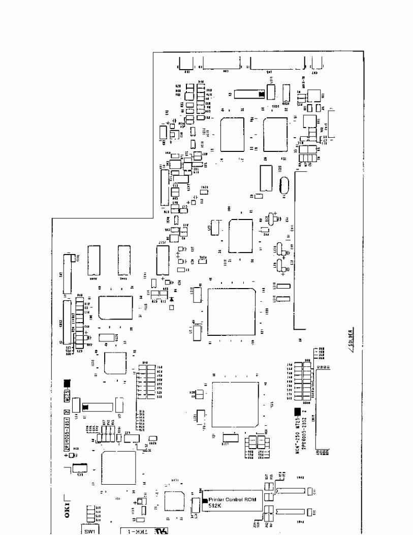

Copyright 1997, Okidata, Division of OKI America, Inc. All rights reserved. See the OKIDATA Business Partner Exchange (BPX) for any updates to this material. (http://bpx.okidata.com)

Page: 153
Service Guide OF2200/2400/2600Chapter A Board Diagrams
A.2.02 Main Control Board (DFCU) Okifax 2400/2600
FunctionThe main control board contains an IC that provides voice answering in the TEL/FAX Mode in accordance with the INPUT/OUTPUT Gate Array and the microprocessor. This board converts parallel send data to serial data, converts serial receive data to parallel data,
modulates/demodulates data, and generates multi-frequency signals for tone dialing. It amplifies signals and sends the amplified signals to a speaker. The main control board houses an 8 MHz Microprocessor, static RAM, ENCODER/DECODER, and a modem IC. This board also monitors the status of the PC1, PC2, B4, and A3 photosensors.
FirmwareNONE
FusesNONE
JumpersNONE
SensorsNONE
SwitchesNONE
Test PointsCN 5 Pin 1: GROUNDCN 5 Pin 13: +5 vdcCN 5 Pin 14: +12 vdcCN 5 Pin 15: -12 vdcCN 12 Pin 2, 5, 8, 11: +5 vdc


Copyright 1997, Okidata, Division of OKI America, Inc. All rights reserved. See the OKIDATA Business Partner Exchange (BPX) for any updates to this material. (http://bpx.okidata.com)

Page: 154
Service Guide OF2200/2400/2600Chapter A Board Diagrams
A.2.03 Printer Control Board (PCNT-250) Okifax 2200
FunctionThe printer control board contains ICs and transistors that drive the registration motor, verification stamp, clutch, and transmit stepper motor, drum motor, and DC fan. This board activates the LED Head in accordance with signals received from the main control board.
FirmwareNONE
FusesNONE
JumpersNONE
SensorsNONE
SwitchesNONE
Test PointsCN 4: Pins 7, 8, 14, 15: +5 vdcCN 4: Pin 9: -12 vdcCN 4: Pin 11: +12 vdcCN 4: Pin 1, 2, 3: +38 vdcCN 4: Pin 4, 5, 6: GROUND


Copyright 1997, Okidata, Division of OKI America, Inc. All rights reserved. See the OKIDATA Business Partner Exchange (BPX) for any updates to this material. (http://bpx.okidata.com)

Page: 155
Service Guide OF2200/2400/2600Chapter A Board Diagrams
A.2.04 Printer Control Board (DFPU) Okifax 2400/2600
FunctionThe printer control board contains ICs and transistors that drive the registration motor, verification stamp, clutch, and transmit stepper motor, drum motor, and DC fan. This board activates the LED Head in accordance with signals received from the main control board.
FirmwareROM: Location O1A: 256 Kbytes: contains Printer Control Program
FusesNONE
JumpersNONE
SensorsNONE
SwitchesDSW1: Used to set the LED Print Head Drive Time.
Test PointsCN 4: Pins 7, 8, 14, 15: +5 vdcCN 4: Pin 9: -12 vdcCN 4: Pin 11: +12 vdcCN 4: Pin 1, 2, 3: +38 vdcCN 4: Pin 4, 5, 6: GROUND


Copyright 1997, Okidata, Division of OKI America, Inc. All rights reserved. See the OKIDATA Business Partner Exchange (BPX) for any updates to this material. (http://bpx.okidata.com)

Page: 156
Service Guide OF2200/2400/2600Chapter A Board Diagrams
A.2.05 Network Control Unit (NCU)
FunctionThis board detects the OFF-HOOK condition, converts received analog data to digital signal levels, generates dial pulses, and detects incoming ring signals when a ring signal of 20 Hz at 25 Vrms is input to line terminals L1 and L2.
FirmwareNONE
FusesNONE
JumpersNONE
SensorsNONE
SwitchesNONE
Test PointsCN 7 Pin 1: GROUNDCN 7 Pin 13: +5 vdcCN 7 Pin 14: +12 vdcCN 7 Pin 15: -12 vdc

Copyright 1997, Okidata, Division of OKI America, Inc. All rights reserved. See the OKIDATA Business Partner Exchange (BPX) for any updates to this material. (http://bpx.okidata.com)

Page: 157
Service Guide OF2200/2400/2600Chapter A Board Diagrams
A.2.06 Power Supply Board (PWU)
FunctionThe power supply board converts the AC input voltage into +5 vdc, +/-12 vdc and +38 vdc for use throughout the printer. This board generates the high voltages needed for the electrostatic printing process.
FirmwareNONE
FusesF1: 6.3 amp AC line fuseF2: 3.15 amp protects the +38 vdc circuitryF3: 5 amp protects the +5 vdc circuitry
JumpersNONE
SensorsPS1: Paper Exit SensorPS2: Paper Sensor (detects the leading edge of the paper)PS3: Inlet Sensor #1PS4: Paper End Sensor (detects the presence of paper in the installed cassette)PS5: Paper Width SensorPS6: Toner Low Sensor
SwitchesSW1: AC Power SwitchSW2: Cover Open Switch
Test PointsCN 4: Pins 7, 8, 14, 15: +5 vdcCN 4: Pin 9: -12 vdcCN 4: Pin 11: +12 vdcCN 4: Pin 1, 2, 3: +38 vdcCN 4: Pin 4, 5, 6: GROUND
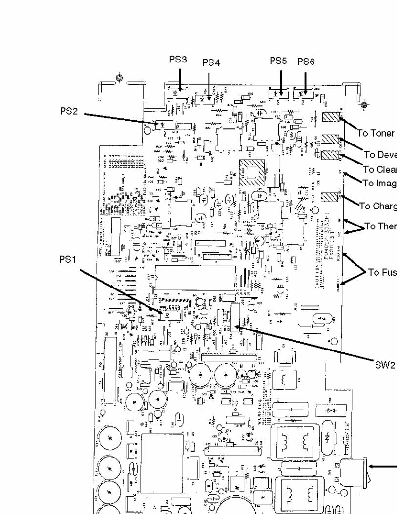

Copyright 1997, Okidata, Division of OKI America, Inc. All rights reserved. See the OKIDATA Business Partner Exchange (BPX) for any updates to this material. (http://bpx.okidata.com)

Page: 158
Service Guide OF2200/2400/2600Chapter A Board Diagrams
A.2.07 Memory Board (MT-25) Okifax 2200
NOTE:The unit MUST be reprogrammed when this board is replaced.
FunctionThe memory board stores system memory data picture memory for ECM send/receive mode, picture memory for memory transmission mode, picture memory for the retransmission of data, and image memory for reception in memory. All system data is stored on this board. A 3.25 volt lithium battery provides battery back-up for all system data.
FirmwareROM1 - 27C010ROM2 - 27C010
FusesNONE
JumpersNONE
SensorsNONE
SwitchesNONE
Test PointsROM 1, 2 or 3: Pin 40 + 5 vdc


Copyright 1997, Okidata, Division of OKI America, Inc. All rights reserved. See the OKIDATA Business Partner Exchange (BPX) for any updates to this material. (http://bpx.okidata.com)

Page: 159
Service Guide OF2200/2400/2600Chapter A Board Diagrams
A.2.08 Memory Board (DFME) Okifax 2400/2600
NOTE:The unit MUST be reprogrammed when this board is replaced.
FunctionThe memory board stores system memory data picture memory for ECM send/receive mode, picture memory for memory transmission mode, picture memory for the retransmission of data, and image memory for reception in memory. A 4.8 Volt battery retains all of this information when AC power is disrupted or removed. All system data is stored on this board. A 3.25 volt lithium battery provides additional battery power for system data back-up.
FirmwareROM1 - 27C4096ROM2 - 27C4096ROM3 - 27C4096
FusesNONE
JumpersNONE
SensorsNONE
SwitchesNONE
Test PointsROM 1, 2 or 3: Pin 40 + 5 vdc


Copyright 1997, Okidata, Division of OKI America, Inc. All rights reserved. See the OKIDATA Business Partner Exchange (BPX) for any updates to this material. (http://bpx.okidata.com)

Page: 160
Service Guide OF2200/2400/2600Chapter A Board Diagrams
A.2.09 Line Interface Board (LINE)
FunctionThis board sends and receives data from the telephone line.
FirmwareNONE
FusesNONE
JumpersNONE
SensorsNONE
SwitchesSW1Ring Volume AdjustmentThree Positions: Low, Medium, High
Test PointsCN 2: Pin 4 + 12 vdcCN 5: Pins 1, 2 - 8 vdc
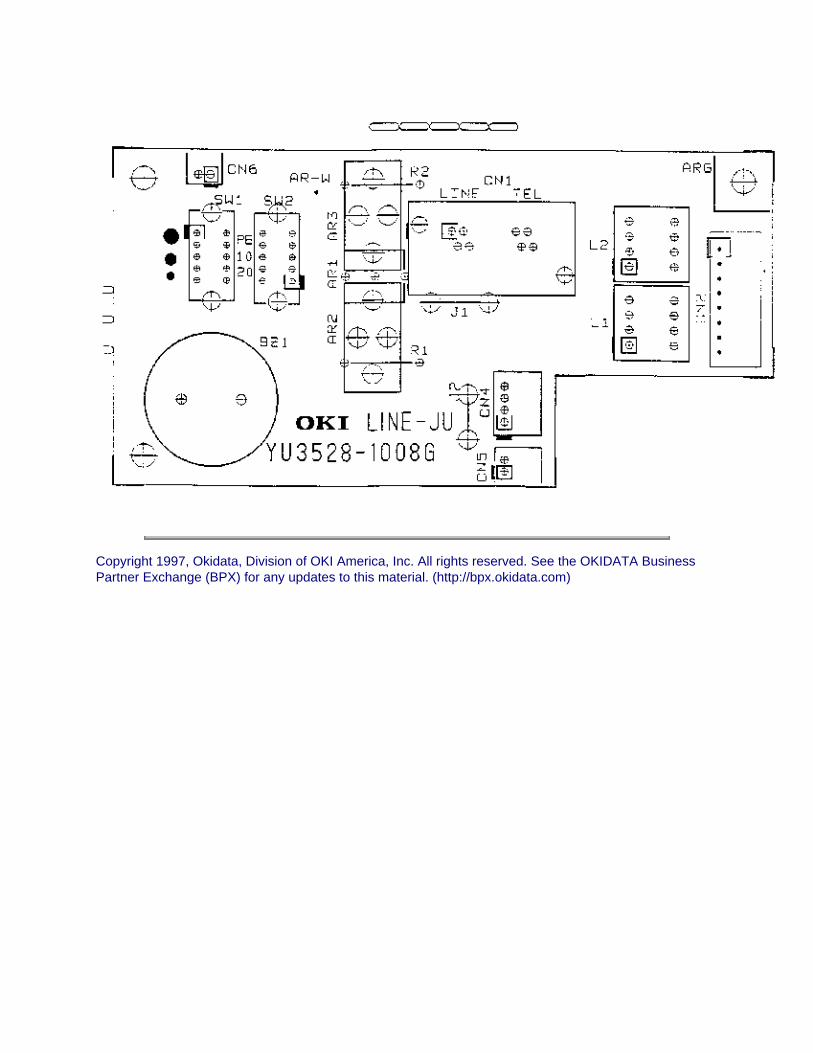
Copyright 1997, Okidata, Division of OKI America, Inc. All rights reserved. See the OKIDATA Business Partner Exchange (BPX) for any updates to this material. (http://bpx.okidata.com)

Page: 161
Service Guide OF2200/2400/2600Chapter A Board Diagrams
A.2.10 Connector Board (CB-250)
FunctionThis board connects the unit to the optional paper tray.FirmwareNONEFusesNONEJumpersNONESensorsNONESwitchesNONETest PointsNONE
Copyright 1997, Okidata, Division of OKI America, Inc. All rights reserved. See the OKIDATA Business

Partner Exchange (BPX) for any updates to this material. (http://bpx.okidata.com)

Page: 162
Service Guide OF2200/2400/2600Chapter A Board Diagrams
Okifax 2200 - 1 of 5


Copyright 1997, Okidata, Division of OKI America, Inc. All rights reserved. See the OKIDATA Business Partner Exchange (BPX) for any updates to this material. (http://bpx.okidata.com)

Page: 163
Service Guide OF2200/2400/2600Chapter A Board Diagrams
Okifax 2200 - 2 of 5


Copyright 1997, Okidata, Division of OKI America, Inc. All rights reserved. See the OKIDATA Business Partner Exchange (BPX) for any updates to this material. (http://bpx.okidata.com)

Page: 164
Service Guide OF2200/2400/2600Chapter A Board Diagrams
Okifax 2200 - 3 of 5


Copyright 1997, Okidata, Division of OKI America, Inc. All rights reserved. See the OKIDATA Business Partner Exchange (BPX) for any updates to this material. (http://bpx.okidata.com)
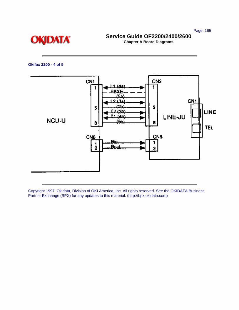
Page: 165
Service Guide OF2200/2400/2600Chapter A Board Diagrams
Okifax 2200 - 4 of 5
Copyright 1997, Okidata, Division of OKI America, Inc. All rights reserved. See the OKIDATA Business Partner Exchange (BPX) for any updates to this material. (http://bpx.okidata.com)

Page: 166
Service Guide OF2200/2400/2600Chapter A Board Diagrams
Okifax 2200 - 5 of 5
Copyright 1997, Okidata, Division of OKI America, Inc. All rights reserved. See the OKIDATA Business Partner Exchange (BPX) for any updates to this material. (http://bpx.okidata.com)

Page: 167
Service Guide OF2200/2400/2600Chapter A Board Diagrams
A.2.12 Interconnect Diagrams (2400/2600)
Okifax 2400/2600 - 1 of 6


Copyright 1997, Okidata, Division of OKI America, Inc. All rights reserved. See the OKIDATA Business Partner Exchange (BPX) for any updates to this material. (http://bpx.okidata.com)

Page: 168
Service Guide OF2200/2400/2600Chapter A Board Diagrams
Okifax 2400/2600 - 2 of 6


Copyright 1997, Okidata, Division of OKI America, Inc. All rights reserved. See the OKIDATA Business Partner Exchange (BPX) for any updates to this material. (http://bpx.okidata.com)

Page: 169
Service Guide OF2200/2400/2600Chapter A Board Diagrams
Okifax 2400/2600 - 3 of 6
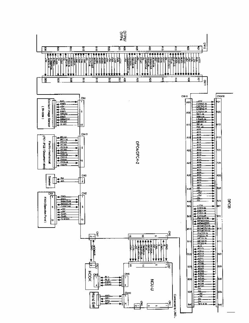

Copyright 1997, Okidata, Division of OKI America, Inc. All rights reserved. See the OKIDATA Business Partner Exchange (BPX) for any updates to this material. (http://bpx.okidata.com)

Page: 170
Service Guide OF2200/2400/2600Chapter A Board Diagrams
Okifax 2400/2600 - 4 of 6
Copyright 1997, Okidata, Division of OKI America, Inc. All rights reserved. See the OKIDATA Business Partner Exchange (BPX) for any updates to this material. (http://bpx.okidata.com)

Page: 171
Service Guide OF2200/2400/2600Chapter A Board Diagrams
Okifax 2400/2600 - 5 of 6
Copyright 1997, Okidata, Division of OKI America, Inc. All rights reserved. See the OKIDATA Business Partner Exchange (BPX) for any updates to this material. (http://bpx.okidata.com)

Page: 172
Service Guide OF2200/2400/2600Chapter A Board Diagrams
Okifax 2400/2600 - 6 of 6


Copyright 1997, Okidata, Division of OKI America, Inc. All rights reserved. See the OKIDATA Business Partner Exchange (BPX) for any updates to this material. (http://bpx.okidata.com)

Page: 173
Service Guide OF2200/2400/2600Chapter B Illustrated Parts
B.1 ILLUSTRATED PARTS LISTING
B.1.01 General InformationThis appendix will assist you in identifying the assemblies and parts of the units. Once you have used Module Two (Failure Analysis) to find a defective part, you can locate the part number in this section. This appendix is cross-referenced to Section Three (Maintenance) to assist you in servicing the printers.
The format for this appendix is a series of tables with diagrams. The table contains the item reference number, the Okidata and Oki-Japan (Oki-J) part numbers, the part description, a comments section, and the disassembly procedure. Items with the comment RSPL (Recommended Spare Parts List), Consumable, or Option are available from Okidata. Items without these comments are usually not stocked. Also note that some items are only available as assemblies. Every effort has been made to clearly indicate which items are in assemblies and which are not.
N/A will appear where a part number is not available.
Please read the Definition of Terms in the following section carefully. It is important that you understand the different types of classifications and their availability.
Please refer to the following resources for current part numbers and pricing.
· Okidata's Bulletin Board (Okilink II) contains current part numbers, prices, and recommended stocking levels for each item listed as a recommended spare part. For instructions on accessing Okilink II, refer to the Service Center Reference Guide.
· Okidata's Faxable Facts is an automated fax document retrieval system. Part numbers and pricing are available through Faxable Facts. For instructions on accessing Faxable Facts, refer to the Service Center Reference Guide.
· Okidata's Technical Information Group is a telephone support line reserved for Authorized Dealers. Part numbers and pricing are available through Technical Information. For instructions on accessing Technical Information, refer to the Service Center Reference Guide.
REMEMBERCurrent part numbers, recommended stocking levels, and pricing information are available through Okilink II, Faxable Facts, and Technical Information. Refer to the Service Center Reference Guide for information on accessing these resources.
Copyright 1997, Okidata, Division of OKI America, Inc. All rights reserved. See the OKIDATA Business Partner Exchange (BPX) for any updates to this material. (http://bpx.okidata.com)

Page: 174
Service Guide OF2200/2400/2600Chapter B Illustrated Parts
B.1.02 Definitions of Terms
RSPLOkidata recommends that this part/assembly be on hand for servicing.
ConsumableA consumable is a supply item which has a specified life and needs to be replaced periodically. It is purchased and installed by the end user. Okidata machines are designed to work exclusively with Okidata consumables. By using genuine Okidata consumable products, the investment made in the equipment will be protected.
OptionAn option is a part/assembly which is added to a product and expands the products functionality. An option may or may not be installed by the end-user. Instructions for installation accompany each option.
Option RSPLOkidata recommends that this part/assembly be on hand for servicing installed options.
DocumentA document is a printed item which supports the service and marketing of a product. Various documents are available from Okidata.
BlankOkidata does not recommend stocking this item. This item should be purchased on an As Required Basis ONLY . The availability of this item is NOT guaranteed by Okidata.
2200This part is found ONLY in the Okifax 2200.
2400This part is found ONLY in the Okifax 2400.
2600This part is found ONLY in the Okifax 2600.
Serial Number IdentificationTo identify the revision level of a unit, record the serial number from the back of the unit. Refer to the following to decode the serial number.
Example Serial Number: 401A0154693Date Code 401 (4 = year. 01 = month)Revision ASerial Number 0154693
NOTE:Please refer to the parts lists for parts differentiation. Please be sure of the parts you need before

ordering to avoid confusion and incorrect parts orders.
Copyright 1997, Okidata, Division of OKI America, Inc. All rights reserved. See the OKIDATA Business Partner Exchange (BPX) for any updates to this material. (http://bpx.okidata.com)

Page: 175
Service Guide OF2200/2400/2600Chapter B Illustrated Parts
B.1.03 Parts Ordering Information
Service Center Reference GuideAll authorized Okidata Dealers may order spare parts and consumables for Okidata products. Orders are placed through Okidata's Logistics Department.
When a technician has successfully completed a product certification course and the Dealer has become service authorized, an information package will be provided to the Dealer. The Okidata Service Center Reference Guide outlines the following.
· Responsibilities of Okidata Service Centers
· Spare parts and consumables information
· Procedures for warranty repairs
· Product training, certification, and authorization
· Product support information
· Okidata depot information and services
· Third party service information
· Information about Okidata's Customer Information Center
· Okidata service and support telephone numbers.
The Service Center Reference Guide contains detailed procedures to follow when ordering parts. Please read, understand , and follow these procedures. Service authorization for a specific product must be obtained before a Dealer can submit warranty claims.Questions regarding the Service Center Reference Guide should be directed to Okidata Dealer Service.
Placing a Parts OrderPlease refer to the Service Center Reference Guide for details on ordering parts.The following information MUST be available before an order is placed.
· Okidata Dealer Authorization Number
· Purchase Order number
· Serial Number / Revision Level of the unit(s)
· Okidata Part Number(s)
Use this Appendix, Okilink II, Faxable Facts, or Technical Information to find the correct part number. Refer to the Service Center Reference Guide for information on contacting Okidata.
Copyright 1997, Okidata, Division of OKI America, Inc. All rights reserved. See the OKIDATA Business Partner Exchange (BPX) for any updates to this material. (http://bpx.okidata.com)
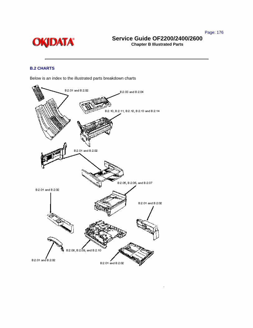
Page: 176
Service Guide OF2200/2400/2600Chapter B Illustrated Parts
B.2 CHARTS
Below is an index to the illustrated parts breakdown charts
.

Description Section
Cabinet Assembly (1 of 2) B.2.01
Cabinet Assembly (2 of 2) B.2.02
Control Panel Assembly (Okifax 2200) B.2.03
Control Panel Assembly (Okifax 2400/2600) B.2.04
Printer Assembly (1 of 3) B.2.05
Printer Assembly (2 of 3) B.2.06
Printer Assembly (3 of 3) B.2.07
Base Assembly (1 of 2) B.2.08
Base Assembly (2 of 2) B.2.09
Scan Assembly (1 of 2) B.2.10
Scan Assembly (2 of 2) B.2.11
Scan Unit (1 of 3) B.2.12
Scan Unit (2 of 3) B.2.13
Scan Unit (3 of 3) B.2.14
Upper Paper Guide Assembly (1 of 2) B.2.15
Upper Paper Guide Assembly (2 of 2) B.2.16
Cables B.2.17
Options B.2.18
Packaging B.2.19
Consumables B.2.20
Documentation B.2.21
Copyright 1997, Okidata, Division of OKI America, Inc. All rights reserved. See the OKIDATA Business Partner Exchange (BPX) for any updates to this material. (http://bpx.okidata.com)

Page: 177
Service Guide OF2200/2400/2600Chapter B Illustrated Parts
B.2.01 Cabinet Assembly (1 of 2)
Part numbers are subject to change. Refer to Section B.1.01 for finding current information.


Copyright 1997, Okidata, Division of OKI America, Inc. All rights reserved. See the OKIDATA Business Partner Exchange (BPX) for any updates to this material. (http://bpx.okidata.com)

Page: 178
Service Guide OF2200/2400/2600Chapter B Illustrated Parts
B.2.02 Cabinet Assembly (2 of 2)
Part numbers are subject to change. Refer to Section B.1.01 for finding current information.

Item
Okidata P/N Oki-J P/N
Description Comments Refer to B.1.02
Disassembly Procedure
9 53071801 2PP4136-1008P001
Cover: IC Card RSPL 3.2.03
10 53071211 1PP4136-1004P011
Cover: Side (Right) 2200/2400
RSPL 3.2.03
10 53071201 1PP4136-1004P001
Cover: Side (Right) 2600
RSPL 3.2.03
11 57001401 4YB3527-1025P001
Speaker RSPL 3.2.03
12 51709701 4PP3512-4707P001
Bracket: Speaker 3.2.03
14 53071401 1PP4136-1006P001
Cover: Side (Left) RSPL 3.2.05 , 3.2.06
17 53071601 1PP4136-1009P001
Cover: Cradle Base RSPL 3.2.06
20 50317201 1PP3529-5016P001
Cover: Cradle RSPL 3.2.06
19 55074002 4YB3529-1030P002
PCB: Hook Switch RSPL 3.2.07
18 56629501 4YS4011-4565P001
Cable: (Modular NCU / TEL)
29 N/A 4PB4083-2500P010
Screw
Copyright 1997, Okidata, Division of OKI America, Inc. All rights reserved. See the OKIDATA Business Partner Exchange (BPX) for any updates to this material. (http://bpx.okidata.com)

Page: 179
Service Guide OF2200/2400/2600Chapter B Illustrated Parts
B.2.03 Control Panel Assembly (Okifax 2200)
Part numbers are subject to change. Refer to Section B.1.01 for finding current information

.

Item
Okidata P/N Oki-J P/N
Description Comments Refer to B.1.02
Disassembly Procedure
1 50105601 4YA4136-1002G201
Panel: Control (Assembly) 2200
RSPL Inc. all items shown
3.2.09
2 N/A 2PP4014-4800P002
Cover: Expanded (B) 2200/2400
Inc. in 1 3.2.09
3 53071901 3PB4014-4777P001
Cover: One-Touch RSPL Inc. in 1 3.2.09
4 53072001 3PB4014-4778P201
Sheet: One-Touch (U) 2200
RSPL Inc. in 1 3.2.09
6 N/A 3PB4014-4769P201
Sheet: Function 2200 Inc. in 1 3.2.09
7 N/A 4PB4014-4776P201
Label: Ten-Key 2200 Inc. in 1 3.2.09
Copyright 1997, Okidata, Division of OKI America, Inc. All rights reserved. See the OKIDATA Business Partner Exchange (BPX) for any updates to this material. (http://bpx.okidata.com)

Page: 180
Service Guide OF2200/2400/2600Chapter B Illustrated Parts
B.2.04 Control Panel Assembly (Okifax 2400/2600)
Part numbers are subject to change. Refer to Section B.1.01 for finding current information


.
Item Okidata P/N Oki-J P/N
Description Comments Refer to B.1.02
Disassembly Procedure
1 50105611 4YA4136-1002G101
Panel: Control (Assembly) 2400
RSPL Inc. all items shown
3.2.09
1 50105610 4YA4136-1002G001
Panel: Control (Assembly) 2600
RSPL Inc. all items shown
3.2.09
2 N/A 2PP4014-4800P002
Cover: Expanded (B) 2200/2400
Inc. in 1 3.2.09
2 53072102 2PP4014-4771P002
Cover: Expanded (A) 2600
Inc. in 1 3.2.09
3 53071901 3PB4014-4777P001
Cover: One-Touch RSPL Inc. in 1 3.2.09
4 53072011 3PB4014-4778P011
Sheet: One-Touch (U) 2400/2600
RSPL Inc. in 1 3.2.09
5 53072201 3PB4014-4779P001
Sheet: One-Touch (D) 2600
Inc. in 1 3.2.09
6 N/A 3PB4014-4769P101
Sheet: Function (1) 2400
Inc. in 1 3.2.09
6 N/A 3PB4014-4769P001
Sheet: Function (1) 2600
Inc. in 1 3.2.09
7 N/A 4PB4014-4776P001
Label: Ten-Key 2400/2600
Inc. in 1 3.2.09
Copyright 1997, Okidata, Division of OKI America, Inc. All rights reserved. See the OKIDATA Business Partner Exchange (BPX) for any updates to this material. (http://bpx.okidata.com)

Page: 181
Service Guide OF2200/2400/2600Chapter B Illustrated Parts
B.2.05 Printer Assembly (1 of 3)
Part numbers are subject to change. Refer to Section B.1.01 for finding current information.

Item Okidata P/N Oki-J P/N
Description Comments Refer to B.1.02
Disassembly Procedure
29 56116901 4YA4083-6300G020
Kit: Image Drum Consumable 3.2.01
30 52106701 4YA4083-6400G020
Kit: Toner Cartridge Consumable 3.2.01
28 53069002 2PA4083-6160G002
Cover: Face Down Stacker (Assembly)
RSPL Inc. 45 - 47
3.2.01 , 3.2.21
45 N/A 1PP4083-6161P001
Cover: Stacker Inc. in 28 3.2.01 , 3.2.21
46 50104801 2PP4083-6162P001
Tray: Stacker Cover Extension
RSPL Inc. in 28 3.2.21
47 51013801 4PB3517-1567P001
Guide: Wire RSPL Inc. in 28 3.2.21
35 53069701 2PP3529-5025P001
Cover: Inner RSPL 3.2.18
41 N/A +T2P4-12-HHC Screw 3.2.20
42 N/A +P(SW+2W)3-25-HHC
Screw 3.2.20
44 N/A +D3-8-G Screw 3.2.20
32 50217601 2PP4083-6801G1
Frame: Lower Base Assembly
RSPL Inc. 36 37 and 40
3.2.20
36 53344301 4PP4083-6033P001
Plate: Ground (RE) Inc. in 32 3.2.20
37 53344401 4PP4083-6056P1
Plate: Ground (BU) Inc. in 32 3.2.20
40 53344501 4PP4083-6043P001
Plate: Transfer Contact
Inc. in 32 3.2.20
31 56111202 3YX4083-6245G2
LED Head Assembly RSPL Inc. 50 51
3.2.21
50 51014601 4PP4083-6173P1
Contact: Ground Clip Not Shown
RSPL Inc. in 31 3.2.21
51 56730201 224A1286P0140
Connector: PC Not Shown
RSPL Inc. in 31 3.2.21
53 56629102 238A1071P0008
Cable: LED Head RSPL 3.2.21

Copyright 1997, Okidata, Division of OKI America, Inc. All rights reserved. See the OKIDATA Business Partner Exchange (BPX) for any updates to this material. (http://bpx.okidata.com)

Page: 182
Service Guide OF2200/2400/2600Chapter B Illustrated Parts
B.2.06 Printer Assembly (2 of 3)
Part numbers are subject to change. Refer to Section B.1.01 for finding current information.


Item Okidata P/N Oki-J P/N
Description Comments Refer to B.1.02
Disassembly Procedure
27 51011001 2PA4083-6130G1
Guide: Manual Feed Assembly
RSPL 3.2.22
21 51010903 4PB4083-3182P003
Strip: Anti-Static 3.2.22
26 53342801 2PA4083-6120G1
Roller: Eject Assembly
RSPL 3.2.22
25 50217501 2YX4083-6100G1
Unit: Fuser 120V (Assembly)
RSPL 3.2.22
22 56511302 4PB4122-1243P002
Motor: Registration Stepper
RSPL 3.2.23
23 51225701 4PP4083-2593P1
Gear: Stepper Motor Idle
RSPL 3.2.23
24 51229301 3PP4083-6076P1
Gear: Reduction RSPL 3.2.23
43 N/A +P(SW)3-4-HHC
Screw 3.2.23
38 51709901 3PP4083-6071G001
Bracket: Motor 3.2.23
39 56511303 4PB4122-1243P003
Motor: Main Stepper RSPL 3.2.23
4 51228901 4PB4083-6024P1
Gear: Hopping Roller Clutch
RSPL 3.2.25
5 50407001 3PB4122-1281P001
Roller: Registration (F)
RSPL 3.2.25
6 51607501 4PP4083-6031P001
Bearing: Registration Roller
3.2.25
18 51010701 4PP4083-6083P1
Plate: Sensor (Inlet) RSPL 3.2.25
19 51010801 4PP4083-6085P1
Plate: Sensor (Outlet)
RSPL 3.2.25
20 50405501 4PP4083-6086G1
Sensor: Toner RSPL 3.2.25
33 53069101 4PP4083-6191G1
Arm: Stacker Cover Damper
RSPL 3.2.25
34 51229401 4PB4083-6197P1
Gear: Stacker Cover Damper
RSPL 3.2.25
3 51607402 4PP4083-6022P2
Bearing RSPL 3.2.24 ,25
49 50219601 3PA4122-1295G001
Assembly: Hopping Roller
RSPL Inc. 1 and 2 3.2.25
1 N/A 3PP4083-6020P001
Shaft: Hopping Roller
Inc. in 49 3.2.25
2 N/A 4PB4122-1280P001
Rubber: Hopping Roller
Inc. in 49 3.2.25
Copyright 1997, Okidata, Division of OKI America, Inc. All rights reserved. See the OKIDATA Business Partner Exchange (BPX) for any updates to this material. (http://bpx.okidata.com)

Page: 183
Service Guide OF2200/2400/2600Chapter B Illustrated Parts
B.2.07 Printer Assembly (3 of 3)
Part numbers are subject to change. Refer to Section B.1.0 1 for finding current information.


Item Okidata P/N Oki-J P/N
Description Comments Refer to B.1.02
Disassembly Procedure
3 51607402 4PP4083-6022P2
Bearing RSPL 3.2.24 , 3.2.25
7 53342601 4YB4083-6040P1
Roller: Transfer RSPL 3.2.24
8 51229001 4PP4083-6042P1
Gear: Transfer Roller RSPL 3.2.24
9 50406901 3PB4122-1244P001
Roller: Pressure RSPL 3.2.24
10 50926401 4PP4122-1273P001
Spring: Pressure Roller Bias
3.2.24
11 51607601 4PP4083-6052P1
Bushing: Pressure Roller
RSPL 3.2.24
12 50805801 3PP4083-6053P1
Lever: Reset (Left) RSPL 3.2.24
13 50805901 3PP4083-6054P1
Lever: Reset (Right) RSPL 3.2.24
14 53068901 3PP4083-6058P1
Arm: Cover Open RSPL 3.2.24
15 50924201 4PP4083-6057P1
Spring: Stacker Cover Reset
RSPL 3.2.24
16 51229101 4PP4083-6080P1
Gear: Fuser Roller Idle
RSPL 3.2.24
17 51229201 4PP4083-6081P1
Gear: Eject Roller Idle
RSPL 3.2.24
Copyright 1997, Okidata, Division of OKI America, Inc. All rights reserved. See the OKIDATA Business Partner Exchange (BPX) for any updates to this material. (http://bpx.okidata.com)

Page: 184
Service Guide OF2200/2400/2600Chapter B Illustrated Parts
B.2.08 Base Assembly (1 of 2)
Part numbers are subject to change. Refer to Section B.1.01 for finding current information.

Item Okidata P/N Oki-J P/N
Description CommentsRefer to B.1.02
Disassembly Procedure
37 55073501 4YU3528-1017G002
PCB: NCU-U RSPL 3.2.04 , 3.2.26
38 55073401 4YU3528-1008G002
PCB: Line-JU RSPL 3.2.04 , 3.2.26
43 N/A 4PB4013-3102P002
Screw 3.2.04 ,3.2.26
35 50106701 2PP4122-1148P001
Package: Shelf 3.2.04
28 56511201 3PB4076-5290P001
Fan RSPL 3.2.27
31 55075301 4YA4134-1006G001
PCB: PCNT-250 2200
RSPL 3.2.27
31 55075501 4YA4135-1009G001
PCB: DFPU 2400/2600
RSPL 3.2.27
41 N/A +P(SW+2W)3-30-HHC
Screw 3.2.27
47 50219101 3PA4122-1312G002
Assembly: Cassette Separator
RSPL Inc. 16 and 17
3.2.28
16 N/A 3PP4122-1169P001
Frame: Separation (F)
Inc. in 47 3.2.28
17 N/A 4PP4122-1188P001
Rubber: Separation (F)
Inc. in 47 3.2.28

46 50219501 2PA4122-1313G001
Assembly: Cassette Guide (Right)
RSPL Inc. 2 - 8 40
3.2.28
2 N/A 1PP4122-1163P001
Guide: Cassette (R) Inc. in 46 3.2.28
3 N/A 4PP4122-1184P001
Lever: Cassette Lock Inc. in 45 46 3.2.28
4 N/A 4PP4122-1185P001
Spring: Lock Inc. in 45 46 3.2.28
5 50806104 4PB4016-1960P004
Rubber: Foot Inc. in 45 46 3.2.28
6 N/A 4PP4122-1176G001
Link: Sheet (R) Inc. in 46 3.2.28
7 N/A 4PP4122-1177P001
Spring: Sheet Inc. in 45 46 3.2.28
8 53345201 4PP4122-1170P001
Block: Link Pull RSPL Inc. in 45 46
3.2.28
40 N/A 4PB4013-3501P003
Washer: Universal Inc. in 45 46 3.2.28
45 50219401 2PA4122-1314G001
Assembly: Cassette Guide (Left)
RSPL Inc 3-5 7 8 21 22 40
3.2.28
21 N/A 1PP4122-1164P001
Guide: Cassette (L) Inc. in 45 3.2.28
22 N/A 4PP4122-1175G001
Link: Sheet (L) Inc. in 45 3.2.28
Copyright 1997, Okidata, Division of OKI America, Inc. All rights reserved. See the OKIDATA Business Partner Exchange (BPX) for any updates to this material. (http://bpx.okidata.com)

Page: 185
Service Guide OF2200/2400/2600Chapter B Illustrated Parts
B.2.09 Base Assembly (2 of 2)
Part numbers are subject to change. Refer to Section B.1.01 for finding current information.


Item Okidata P/N Oki-J P/N
Description Comments Refer to B.1.02
Disassembly Procedure
1 53071301 1PP4136-1005P001
Cover: Sub (R) RSPL 3.2.18
24 51011401 4PP4083-6082P1
Plate: Paper Supply Sensor
RSPL 3.2.25
26 51011501 3PP4083-6154P1
Plate: Cassette Sensor
RSPL 3.2.25
9 * N/A 1PP4122-1165P001
Cassette: Universal Inc. in 13 of p. B-8 3.2.28
10 * N/A 3PP4122-1166P001
Guide: Universal (R) Inc. in 13 of p. B-8 3.2.28
11 * N/A 3PP4122-1167P001
Guide: Universal (L) Inc. in 13 of p. B-8 3.2.28
12 * N/A 3PP4083-2327P001
Rack Inc. in 13 of p. B-8 3.2.28
13 * N/A 4PP4083-2328P001
Pinion Inc. in 13 of p. B-8 3.2.28
14 * N/A 2PP4122-1172P001
Plate: Sheet Inc. in 13 of p. B-8 3.2.28
15 * 51113110 4PB4083-2104P010
Cork: Friction Inc. in 13 of p. B-8 3.2.28
20 * N/A 3PP4122-1168P001
Guide: Universal (T) Inc. in 13 of p. B-8 3.2.28
18 50926301 4PP4122-1178P001
Spring: Separation (F)
RSPL 3.2.28
19 57001501 3PP4122-1171P001
Indicator: Paper Supply
RSPL 3.2.28
23 * *
51014201 1PP4122-1144P001
Plate: Base 3.2.28
25 * *
52202601 4YC4061-5115P001
Tape: Teflon 3.2.28
27 51710101 4PP4122-1151P001
Bracket: Inlet 3.2.28

29 51710201 2PB4122-1145P001
Insulator 3.2.28
30 51710301 3PB4122-1271P001
Insulator (S) 3.2.28
32 50516501 4PB4122-1245P001
Spacer 3.2.28
33 56730001 3PA4083-6090G1
Assembly: Contact RSPL 3.2.28
34 56413401 4YB4049-1820P001
Unit: Power Supply (120V)
RSPL 3.2.28
42 N/A +P(SW+2W)4-8-HHC
Screw 3.2.28
43 N/A 4PB4013-3102P002
Screw
44 N/A 4PP4083-6228P001
Spring 3.2.28
Copyright 1997, Okidata, Division of OKI America, Inc. All rights reserved. See the OKIDATA Business Partner Exchange (BPX) for any updates to this material. (http://bpx.okidata.com)
Page: 186
Service Guide OF2200/2400/2600Chapter B Illustrated Parts
B.2.10 Scan Assembly (1 of 2)
Part numbers are subject to change. Refer to Section B.1.01 for finding current information.


Item Okidata P/N Oki-J P/N
Description Comments Refer to B.1.02
Disassembly Procedure
18 70027001 4YA4135-1014G002
RS232 Interface Kit Option N/A
19 50219001 2PP4122-1190P001
Base: Scanner (L)
3 50218901 2PP4122-1189P001
Base: Scanner (R)
21 50806201 3PP4122-1159P001
Stay: Document Guide
RSPL 3.2.02
24 N/A 4PP4083-2500P008
Screw 3.2.02
11 55075201 4YA4134-1005G001
PCB: ME 250 2200 RSPL 3.2.08
11 55075402 4YA4135-1008G002
PCB: DFME-2 2400 RSPL 3.2.08
11 55075401 4YA4135-1008G001
PCB: DFME 2600 RSPL 3.2.08
12 51710401 2PP4122-1147P001
Bracket: DFME 3.2.08
2 50806301 4PP4122-1336P001
Hinge: Scanner (R) 3.2.09
20 50806302 4PP4122-1336P002
Hinge: Scanner (L) 3.2.09
10 53071701 2PP4122-1158P001
Cover: (U) RSPL 3.2.12

1 51013701 1PP4122-1091P001
Guide: Paper (M) RSPL 3.2.13
25 N/A 4PP3529-5115P001
Cable: Ground 3.2.13
26 50806501 4LP-1466
Tie: Wire (Goes on Paper Guide M)
RSPL 3.2.13
22 51013501 1PP3527-5225P001
Guide: Paper (E) 2200/2400
RSPL 3.2.14
22 51013502 1PP3527-5225P002
Guide: Paper (E) 2600
RSPL 3.2.14
5 50927701 4PP4122-1290P1
Spring: Release Guide (R)
RSPL 3.2.18
27 52202801 4PB4122-1288P1
Mylar: Exit Strip (Guide Rel Assy)
RSPL 3.2.18
6 51012801 3PA3529-5076G1
Guide: Release Assembly
RSPL Inc. 7 - 9 3.2.18
7 N/A 1PP3529-5029P001
Guide: Release Inc. in 6 3.2.18
8 N/A 4PP3529-5137P001
Bias: Spring Inc. in 6 3.2.18
9 N/A 4PP4083-2024P001
Roller: Eject Inc. in 6 3.2.18
Copyright 1997, Okidata, Division of OKI America, Inc. All rights reserved. See the OKIDATA Business Partner Exchange (BPX) for any updates to this material. (http://bpx.okidata.com)
Page: 187
Service Guide OF2200/2400/2600Chapter B Illustrated Parts
B.2.11 Scan Assembly (2 of 2)
Part numbers are subject to change. Refer to Section B.1.01 for finding current information.
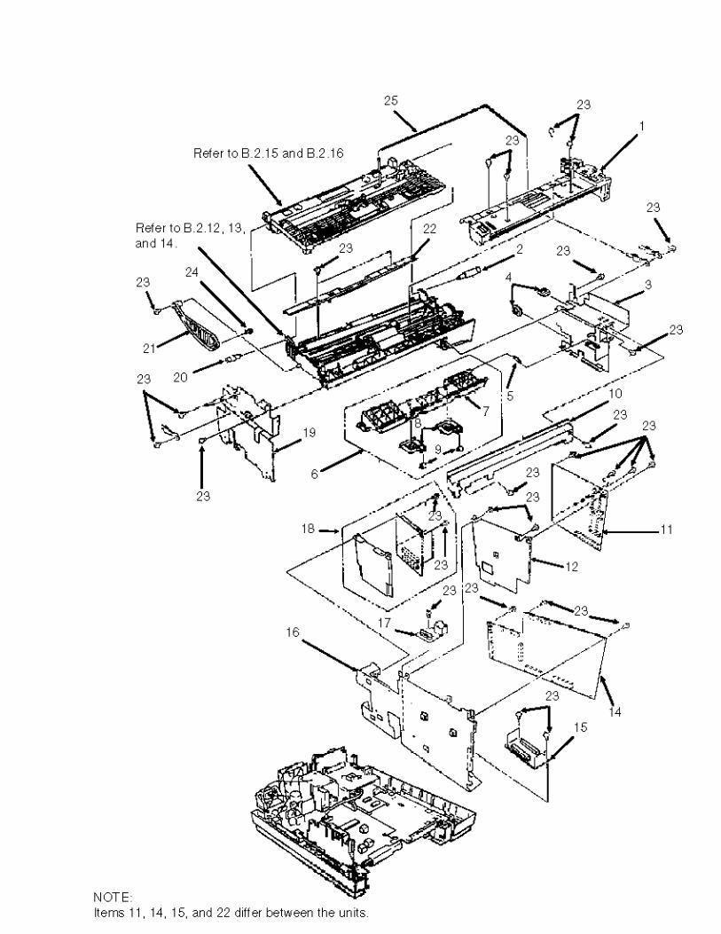

Item Okidata P/N Oki-J P/N
Description Comments Refer to B.1.02
Disassembly Procedure
4 51710701 4PB3527-5800P001
Edge Saddle 3.2.19
15 55075901 N/A PCB: CB -250 2200 3.2.19
15 55076202 N/A PCB: DFCB-2 2400/2600
3.2.19
23 N/A 4PP4013-3102P002
Screw 3.2.19
14 55076001 N/A PCB: MT-25 2200 3.2.19
14 55076102 N/A PCB: DFCU/MCNT-350 2400/2600
3.2.19
16 51710501 1PP4122-1146P001
Bracket: DFCU 3.2.23
17 55073901 4YB3529-1037P001
PCB: Second Tray Interface
RSPL 3.2.19
Copyright 1997, Okidata, Division of OKI America, Inc. All rights reserved. See the OKIDATA Business Partner Exchange (BPX) for any updates to this material. (http://bpx.okidata.com)
Page: 188
Service Guide OF2200/2400/2600Chapter B Illustrated Parts
B.2.12 Scan Unit (1 of 3)
Part numbers are subject to change. Refer to Section B.1.01 for finding current information.

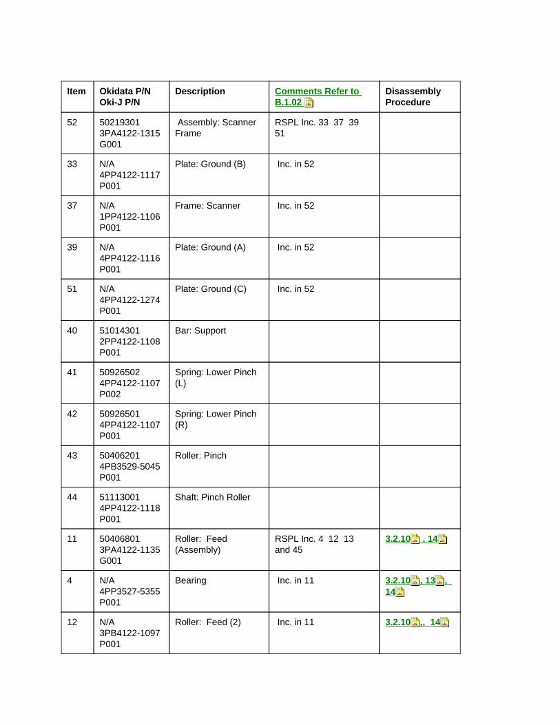
Item Okidata P/N Oki-J P/N
Description Comments Refer to B.1.02
Disassembly Procedure
52 50219301 3PA4122-1315G001
Assembly: Scanner Frame
RSPL Inc. 33 37 39 51
33 N/A 4PP4122-1117P001
Plate: Ground (B) Inc. in 52
37 N/A 1PP4122-1106P001
Frame: Scanner Inc. in 52
39 N/A 4PP4122-1116P001
Plate: Ground (A) Inc. in 52
51 N/A 4PP4122-1274P001
Plate: Ground (C) Inc. in 52
40 51014301 2PP4122-1108P001
Bar: Support
41 50926502 4PP4122-1107P002
Spring: Lower Pinch (L)
42 50926501 4PP4122-1107P001
Spring: Lower Pinch (R)
43 50406201 4PB3529-5045P001
Roller: Pinch
44 51113001 4PP4122-1118P001
Shaft: Pinch Roller
11 50406801 3PA4122-1135G001
Roller: Feed (Assembly)
RSPL Inc. 4 12 13 and 45
3.2.10 , 14
4 N/A 4PP3527-5355P001
Bearing Inc. in 11 3.2.10 , 13 , 14
12 N/A 3PB4122-1097P001
Roller: Feed (2) Inc. in 11 3.2.10 ,, 14
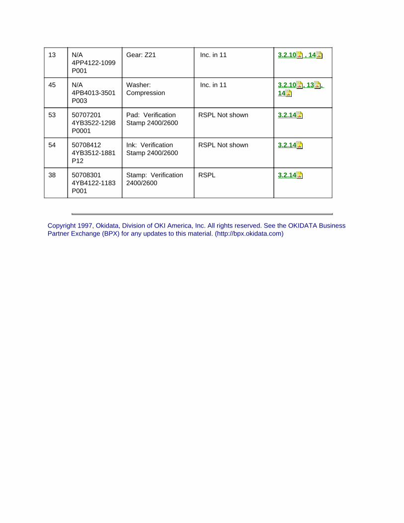
13 N/A 4PP4122-1099P001
Gear: Z21 Inc. in 11 3.2.10 , 14
45 N/A 4PB4013-3501P003
Washer: Compression
Inc. in 11 3.2.10 , 13 , 14
53 50707201 4YB3522-1298P0001
Pad: Verification Stamp 2400/2600
RSPL Not shown 3.2.14
54 50708412 4YB3512-1881P12
Ink: Verification Stamp 2400/2600
RSPL Not shown 3.2.14
38 50708301 4YB4122-1183P001
Stamp: Verification 2400/2600
RSPL 3.2.14
Copyright 1997, Okidata, Division of OKI America, Inc. All rights reserved. See the OKIDATA Business Partner Exchange (BPX) for any updates to this material. (http://bpx.okidata.com)

Page: 189
Service Guide OF2200/2400/2600Chapter B Illustrated Parts
B.2.13 Scan Unit (2 of 3)
Part numbers are subject to change. Refer to Section B.1.01 for finding current information.


Item Okidata P/N Oki-J P/N
Description Comments Refer to B.1.02
Disassembly Procedure
1 50407201 2PA4122-1131G001
Roller: Sensor Assembly
RSPL Inc. 2 - 5 45 and 49
3.2.13
2 N/A 2PB4122-1092P001
Roller: Sensor Inc. in 1 3.2.13
3 N/A 4PP4122-1099P001
Gear: Z21 Inc. in 1 3.2.13
4 N/A 4PP3527-5355P001
Bearing Inc. in 1 18 23 3.2.103.2.13 3.2.14
5 N/A 4PB4013-4107P001
Collar Inc. in 1 3.2.13
45 N/A 4PB4013-3501P003
Washer: Compression
Inc. in 1 18 23 3.2.10 3.2.13 3.2.14
49 N/A 4PB4013-4107P002
Collar Inc. in 1 3.2.13
50 50926201 4PP4122-1272P001
Spring: Release RSPL 3.2.13
23 50406701 3PA4122-1134G001
Roller: Sub (Assembly)
RSPL Inc. 4 24 25 and 45
3.2.13
24 N/A 3PB4122-1098P001
Roller: Sub Inc. in 23 3.2.13
25 N/A 4PP3527-5027P001
Gear: A (Z20) Inc. in 23 3.2.13
18 50407101 3YX4122-1133G001
Roller: ADF Assembly
RSPL Inc. 4 19-22 45
3.2.13
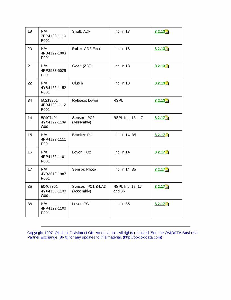
19 N/A 3PP4122-1110P001
Shaft: ADF Inc. in 18 3.2.13
20 N/A 4PB4122-1093P001
Roller: ADF Feed Inc. in 18 3.2.13
21 N/A 4PP3527-5029P001
Gear: (Z28) Inc. in 18 3.2.13
22 N/A 4YB4122-1152P001
Clutch Inc. in 18 3.2.13
34 50218801 4PB4122-1112P001
Release: Lower RSPL 3.2.13
14 50407401 4YX4122-1139G001
Sensor: PC2 (Assembly)
RSPL Inc. 15 - 17 3.2.17
15 N/A 4PP4122-1111P001
Bracket: PC Inc. in 14 35 3.2.17
16 N/A 4PP4122-1101P001
Lever: PC2 Inc. in 14 3.2.17
17 N/A 4YB3512-1987P001
Sensor: Photo Inc. in 14 35 3.2.17
35 50407301 4YX4122-1138G001
Sensor: PC1/B4/A3 (Assembly)
RSPL Inc. 15 17 and 36
3.2.17
36 N/A 4PP4122-1100P001
Lever: PC1 Inc. in 35 3.2.17
Copyright 1997, Okidata, Division of OKI America, Inc. All rights reserved. See the OKIDATA Business Partner Exchange (BPX) for any updates to this material. (http://bpx.okidata.com)

Page: 190
Service Guide OF2200/2400/2600Chapter B Illustrated Parts
B.2.14 Scan Unit (3 of 3)
Part numbers are subject to change. Refer to Section B.1.01 for finding current information.
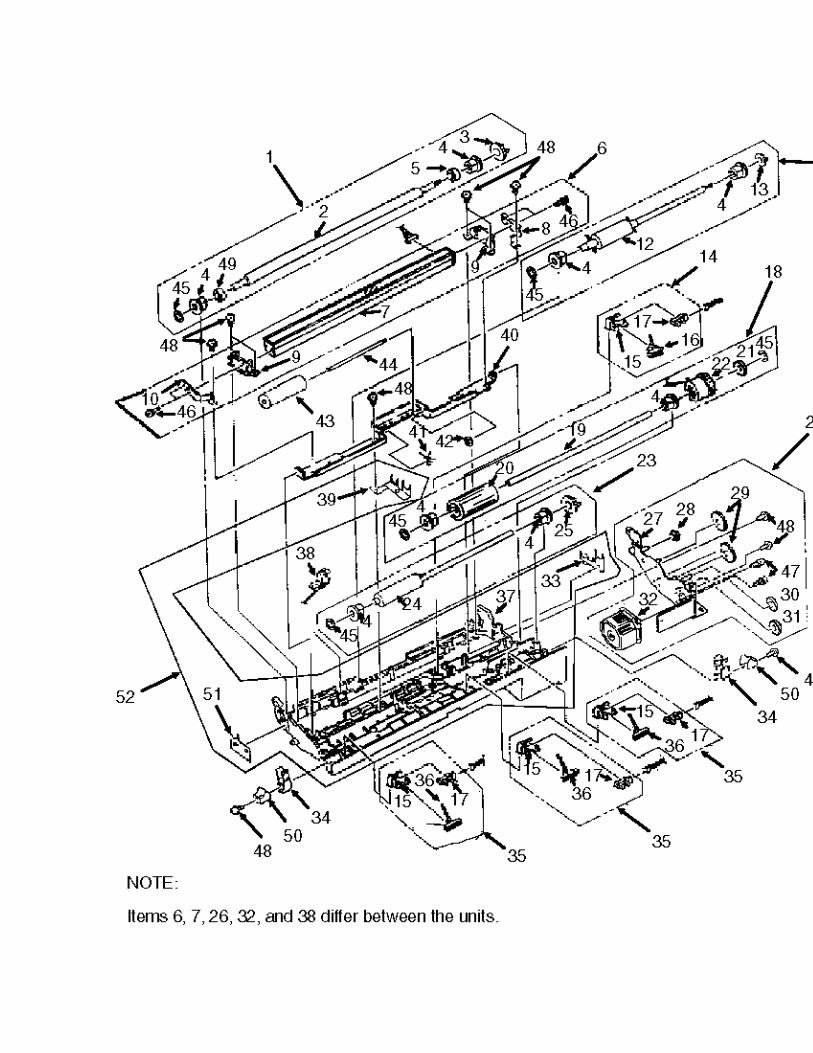

Item Okidata P/N Oki-J P/N
Description Comments Refer to B.1.02
Disassembly Procedure
6 50407502 3YX4122-1137G002
Sensor: Image (B4) Assembly 2200/2400
RSPL Inc. 7 - 10 46 and 48
3.2.15
6 50407501 3YX4122-1137G001
Sensor: Image (A3) Assembly 2600
RSPL Inc. 7 - 10 46 and 48
3.2.15
7 N/A 4YB4122-1264P001
Sensor: B4 2200/2400
Inc. in 6 3.2.15
7 N/A 4YB4122-1266P001
Sensor: A3 2600 Inc. in 6 3.2.15
8 N/A 4PP4122-1122P001
Plate: Ground (SR) Inc. in 6 3.2.15
9 N/A 3PP3527-5224P001
Holder: Sensor Inc. in 6 3.2.15
10 N/A 4PP4122-1121P001
Plate: Ground (SL) Inc. in 6 3.2.15
46 N/A 4PB4013-3099P008
Screw Inc. in 6 3.2.15
26 53345002 3YX4122-1136G002
Frame: Gear Assembly 2200
RSPL Inc. 27 - 32 47 & 48
3.2.16
26 53345001 3YX4122-1136G001
Frame: Gear Assembly 2400/2600
RSPL Inc. 27 - 32 47 & 48
3.2.16
27 N/A 3PP4122-1140G001
Gear: Frame Inc. in 26 3.2.16
28 N/A 4PP4122-1119P001
Gear (Z17/26) Inc. in 26 3.2.16
29 N/A 4PP4122-1104P001
Gear: (Z45) Inc. in 26 3.2.16

30 N/A 4PP4122-1102P001
Gear: Idle (Z30) Inc. in 26 3.2.16
31 N/A 4PP4122-1103P001
Gear: (Z19/52) Inc. in 26 3.2.16
32 56511501 4YB4122-1182P001
Motor: Scan 2200 RSPL Inc. in 26 3.2.16
32 56511401 4YB4122-1181P001
Motor: Scan 2400/2600
RSPL Inc. in 26 3.2.16
47 N/A + P (SW) 3-6 HHC
Screw Inc. in 26 3.2.15 16
48 N/A 4PB4013-3102P002
Screw Inc. in 6 26 3.2.15 16
Copyright 1997, Okidata, Division of OKI America, Inc. All rights reserved. See the OKIDATA Business Partner Exchange (BPX) for any updates to this material. (http://bpx.okidata.com)

Page: 191
Service Guide OF2200/2400/2600Chapter B Illustrated Parts
B.2.15 Upper Paper Guide Assembly (1 of 2)
Part numbers are subject to change. Refer to Section B.1.01 for finding current information.


Item Okidata P/N Oki-J P/N
Description Comments Refer to B.1.02
Disassembly Procedure
1 50406201 4PP3529-5045P001
Roller: Pinch 3.2.10
2 51113001 4PP4122-1118P001
Shaft: Pinch Roller 3.2.10
3 50926601 4PP4122-1089P001
Spring: Upper Pinch (L)
3.2.10
4 50926602 4PP4122-1089P002
Spring: Upper Pinch (R)
3.2.10
5 51710601 4PP4122-1120P001
Bracket: Pinch Roller 3.2.10
6 53339201 2PP3527-5228P001
Plate: Support 3.2.10
7 53339402 4PP3527-5236P002
Plate: Earth (ADF) 3.2.10
8 53339401 4PP3527-5236P001
Plate: Earth (ADF) (L)
3.2.10
9 50407601 3PA4122-1141G001
Roller: Feed (Assembly) 1
RSPL Inc. 10 - 12 27 3.2.10
10 N/A 3PB4122-1096P001
Roller: Feed (1) Inc. in 9 3.2.10
11 N/A 4PP3527-5355P001
Bearing Inc. in 9 3.2.10
12 N/A 4PP3527-5028P001
Gear: (Z30) Inc. in 9 3.2.10
27 N/A 4PB4013-3501P003
Washer: Compression
Inc. in 9 3.2.10

13 50926001 4PP3527-5244P001
Spring: ADF RSPL 3.2.10
14 53061201 4PP3527-5221P1
Arm: ADF Tension RSPL 3.2.10
15 50218701 4PB4122-1105P001
Release : Upper RSPL 3.2.10
16 51304801 4PB4122-1162P001
Brush: Static (B) 3.2.10
25 53339801 4PP3527-5153P1
Plate: ADF Back-Up RSPL 3.2.10
26 51304701 4PB4122-1161P001
Brush: Static (A) 3.2.10
28 N/A 4PB4013-3102P002
Screw 3.2.10
29 50219201 4PA3527-5267G001
Assembly: Sub and Pinch Roller Guide
RSPL Inc. 22 and 23 3.2.10
22 N/A 3PP3527-5216P001
Guide: Sub Pinch Roller
Inc. in 29 3.2.10
23 N/A 4PP3527-5217P001
Roller: Sub Pinch Inc. in 29 3.2.10
Copyright 1997, Okidata, Division of OKI America, Inc. All rights reserved. See the OKIDATA Business Partner Exchange (BPX) for any updates to this material. (http://bpx.okidata.com)

Page: 192
Service Guide OF2200/2400/2600Chapter B Illustrated Parts
B.2.16 Upper Paper Guide Assembly (2 of 2)
Part numbers are subject to change. Refer to Section B.1.01 for finding current information.


Item Okidata P/N Oki-J P/N
Description Comments Refer to B.1.02
Disassembly Procedure
17 51013601 1PP4122-1090P001
Guide: Paper Upper RSPL 3.2.09
24 50926101 4PP3527-5165P001
Spring: Sub Pinch RSPL 3.2.10
18 53339501 4PA3527-5266G1
Rubber: ADF Separation (Assembly)
RSPL Inc. 19 - 21 3.2.11
19 N/A 4PP3527-5249P001
Rubber: Separation Inc. in 18 3.2.11
20 N/A NITTO NO. 513
Tape (10x36mm) Inc. in 18 3.2.11
21 N/A 4PP3527-5346P001
Mylar: Separation Inc. in 18 3.2.11
Copyright 1997, Okidata, Division of OKI America, Inc. All rights reserved. See the OKIDATA Business Partner Exchange (BPX) for any updates to this material. (http://bpx.okidata.com)

Page: 193
Service Guide OF2200/2400/2600Chapter B Illustrated Parts
B.2.17 Cables
Part numbers are subject to change. Refer to Section B.1.01 for finding current information.


Item Okidata P/N Oki-J P/N
Description Comments Refer to B.1.02
Disassembly Procedure
4 70027001 4YA4135-1014G002
RS232 Interface Kit Option Inc. 4A
4A N/A 4YS3512-1688P003
Cable: SIO-DFCU Option Inc. in 4
6 56629601 4YS4111-2926P001
Cable: NCU-MT25/DFCU (15 Pin)
7 57001401 4YB3527-1025P001
Speaker RSPL 3.2.03
8 56629701 4YS4111-4378P001
Cable: Flat (PT25-MT25) 2200
8 56629801 4YS4111-4368P001
Cable: Flat (DFPU-DFCU) 2400/2600
9 56629901 4YS4111-2927P001
Cable: PT25/DFPU- 2nd Tray
10 56630001 4YS4111-2919P001
Cable: PWU-PT25/DFPU
11 56630101 4YS4111-4367P001
Cable: Flat (PWU-PT25/DFPU)
12 56511201 3PB4076-5290P001
Fan RSPL 3.2.27
13 50708301 4YB4122-1183P001
Stamp: Verification 2400/2600
RSPL 3.2.14
14 56630202 4YS4111-2925P002
Cable: Motor/Clutch - PT25 2200
14 56630201 4YS4111-2925P001
Cable: Motor/Clutch - DFPU 2400/2600

15 56630301 4YS4111-2932P001
Cable: Hook Switch MT-25/DFCU
3.2.05
16 56629501 4YS4011-4565P001
Cable: Modular-NCU / TEL
18 56630501 4YS4111-2918P001
Cable: CIS-MT25/DFCU
19 56630602 4YS4111-2917P002
Cable: PC1 2 / Size-MT25/DFCU 2200/2400
19 56630601 4YS4111-2917P001
Cable: PC1 2 / Size-MT25/DFCU 2600
20 56630701 4YS4111-2923P001
Cable: OPE-MT25/DFCU
23 56630801 4YS4111-2920P001
Cable: NCU-Line (8 Pin)
25 56630901 4YS4111-2921P001
Cable: Hook Switch NCU / TEL
26 56631001 4YS4111-2924P001
Cable: NCU-Line (2 Pin)
27 56621001 236A3161P0002
Cord: Modular Telephone
RSPL 3.2.01
28 56618901 4YS3512-1485P001
Cord: AC Power RSPL 3.2.01
Copyright 1997, Okidata, Division of OKI America, Inc. All rights reserved. See the OKIDATA Business Partner Exchange (BPX) for any updates to this material. (http://bpx.okidata.com)

Page: 194
Service Guide OF2200/2400/2600Chapter B Illustrated Parts
B.2.18 Options
Part numbers are subject to change. Refer to Section B.1.01 for finding current information.
Item Okidata P/N Oki-J P/N
Description CommentsRefer to B.1.02
Disassembly Procedure
1 70026101 4YA4083-6250G20
Tray: Legal/Universal Paper (100 Sheet Capacity)
Option 3.2.01
2 70025301 4YA3529-1069G1
1 MB Memory Expansion Kit
Option N/A
2 70026801 4YA3529-1069G002
2 MB Memory Expansion Kit
Option N/A
2 70026901 4YA3529-1069G003
4 MB Memory Expansion Kit
Option N/A
3 70025401 N/A UST-250 Second Tray
Option N/A
4 70026601 4YA4122-1248G002
UST-500 Second Tray
Option N/A

5 70027001 4YA4135-1014G002
RS232 Interface Kit Option N/A
Copyright 1997, Okidata, Division of OKI America, Inc. All rights reserved. See the OKIDATA Business Partner Exchange (BPX) for any updates to this material. (http://bpx.okidata.com)

Page: 195
Service Guide OF2200/2400/2600Chapter B Illustrated Parts
B.2.19 Packaging
Part numbers are subject to change. Refer to Section B.1.01 for finding current information.


Item Okidata P/N Oki-J P/N
Description Comments Refer to B.1.02
Disassembly Procedure
1 53557121 4PP4025-3117P211
Sheet: Top Cardboard
N/A
2 53574701 3PP4136-1031P001
Tray: Accessory N/A
3 53574801 3PP4136-1030P001
Foam: Packaging (Set)
Inc. 4 5 6 and 7 N/A
4 N/A Left Cushion Top N/A
5 N/A Right Cushion Top N/A
6 N/A Left Cushion Bottom N/A
7 N/A Right Cushion Bottom
N/A
8 N/A Poly Bag N/A
9 53570101 4PP4099-1045P005
Box: Graphic N/A
11 52051701 Label: Box ABCD N/A
12 52031630 4PP3522-3260P025
Label: Doc Cert. N/A
Copyright 1997, Okidata, Division of OKI America, Inc. All rights reserved. See the OKIDATA Business Partner Exchange (BPX) for any updates to this material. (http://bpx.okidata.com)
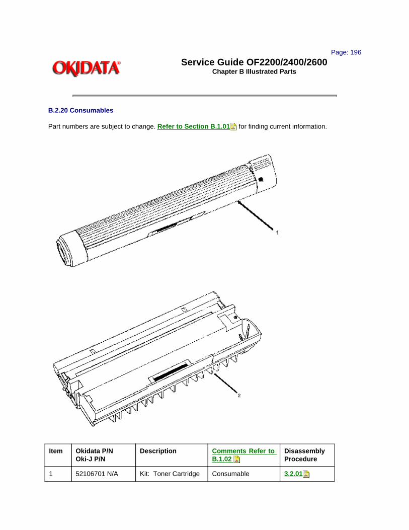
Page: 196
Service Guide OF2200/2400/2600Chapter B Illustrated Parts
B.2.20 Consumables
Part numbers are subject to change. Refer to Section B.1.01 for finding current information.
Item Okidata P/N Oki-J P/N
Description Comments Refer to B.1.02
Disassembly Procedure
1 52106701 N/A Kit: Toner Cartridge Consumable 3.2.01

2 56116901 N/A Kit: Image Drum Consumable 3.2.01
Copyright 1997, Okidata, Division of OKI America, Inc. All rights reserved. See the OKIDATA Business Partner Exchange (BPX) for any updates to this material. (http://bpx.okidata.com)

Page: 197
Service Guide OF2200/2400/2600Chapter B Illustrated Parts
B.2.21 Documentation
Part numbers are subject to change. Refer to Section B.1.01 for finding current information
* To order Marketing Literature, complete an Okidata Marketing Literature Order Form. Fax the completed form to Okidata Marketing Communications.
* * An Okidata Marketing Literature Order Form can be obtained by faxing your request to Okidata Marketing Communications.
Refer to the Service Center Reference Guide for information on contacting Okidata.
Item Okidata P/N Oki-J P/N
Description Comments Refer to B.1.02
Disassembly Procedure
1 58234202 N/A Okifax 2200/2400/2600 Service Training Kit
Document N/A
2 58234301 N/A Okifax 2200 User's Documentation Package
Documentation Inc. 3 4 and 5
N/A
3 58302101 N/A Kraft Bag Document N/A
4 58301401 N/A Quick Reference Guide 2200
Document N/A
5 59262401 N/A Operator's Guide 2200
Document N/A
6 58234401 N/A Okifax 2400/2600 User's Documentation Package
Documentation Inc. 7 8 and 9
7 58302101 N/A Kraft Bag Document N/A
8 58301501 N/A Quick Reference Guide 2400/2600
Document N/A
9 59263301 N/A Operator's Guide 2400/2600
Document N/A

10 58302502 Installation Instructions for Second Tray
Document N/A
11 N/A N/A Okifax Marketing Literature
Document N/A
12 N/A N/A Okidata Marketing Literature Order Form
Document N/A
Copyright 1997, Okidata, Division of OKI America, Inc. All rights reserved. See the OKIDATA Business Partner Exchange (BPX) for any updates to this material. (http://bpx.okidata.com)

Page: 198
Service Guide OF2200/2400/2600Chapter B Illustrated Parts
Illustrated Parts Listing for the Okifax UST-500
Optional Second Paper Tray
Copyright 1997, Okidata, Division of OKI America, Inc. All rights reserved. See the OKIDATA Business Partner Exchange (BPX) for any updates to this material. (http://bpx.okidata.com)

Page: 199
Service Guide OF2200/2400/2600Chapter B Illustrated Parts

Copyright 1997, Okidata, Division of OKI America, Inc. All rights reserved. See the OKIDATA Business Partner Exchange (BPX) for any updates to this material. (http://bpx.okidata.com)
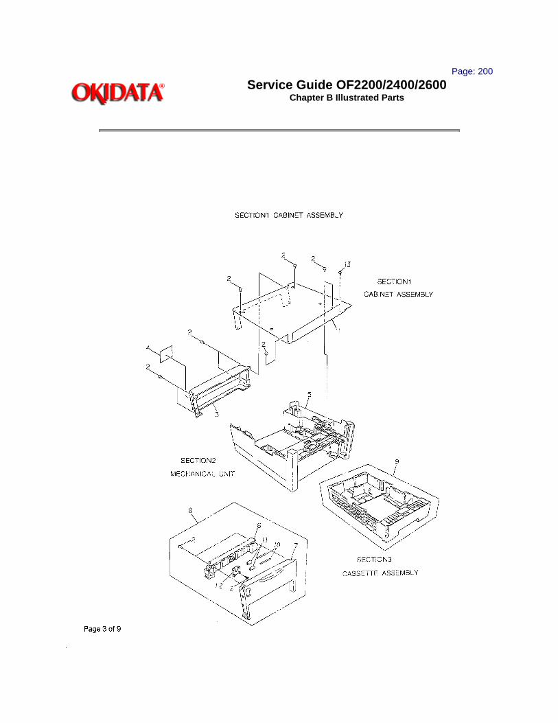
Page: 200
Service Guide OF2200/2400/2600Chapter B Illustrated Parts

UST500 Sec.1
No. OKI Parts Number ODA Parts Number
Description Qty
1 2PP4122-1196P001 51015301 PLATE, Upper 1
2 4PB4013-3102P002 N/A Screw 13
3 1PP4122-1242P001 53072401 COVER, Rear (ST) 1
4 3PB4012-2902P001 N/A PLATE, Model Name 1
5 1PA4122-1252G001
N/A MECHANICAL UNIT 1
6 2PP4122-1208P001 Part of # 8 GUIDE, Sheet (I) 1
7 1PP4122-1211P001 Part of # 8 GUIDE, SHEET (O) 1
8 2PA4122-1251G001
51014801 SHEET GUIDE ASSEMBLY 1
9 1PA4122-1250G001
50107301 CASSETTE ASSEMBLY 1
10 4PP4122-1298P001 Part of # 8 SHAFT, Roller 2
11 4PP4083-6316P001 Part of # 8 Roller, Pressure 2
12 4PP4122-1319P001 Part of # 8 BRACKET, Roller 1
13 4PB4013-3102P003 N/A Screw 2
Copyright 1997, Okidata, Division of OKI America, Inc. All rights reserved. See the OKIDATA Business Partner Exchange (BPX) for any updates to this material. (http://bpx.okidata.com)

Page: 201
Service Guide OF2200/2400/2600Chapter B Illustrated Parts

UST500 Sec.2
No. OKI Parts Number ODA Parts Number
Description Qty
1 3PA4122-1258G001
Part of # 49 SUB ROLLER ASSEMBLY 1
2 4PB4013-3501P002 Part of # 49 WASHER, Compression 3
3 4PP3512-3729P001 Part of # 49 GEAR, Roller Feed Top 1
4 4PP3526-3071P001 Part of # 49 BUSHING, Metal 2
5 4PB4122-1201P001 Part of # 49 SUB ROLLER (ST) 1
6 4PP3527-5034P001 Part of # 49 GEAR (Z16) 1
7 4PB4013-3501P003 N/A WASHER, COMPRESSION 5
8 3PP4122-1202G001
Part of # 49 BRACKET, Sub Roller 1
9 4PP3522-3473P001 Part of # 49 GEAR, Feed # 1 (Z37) 1
10 3PP4122-1206P001 Part of # 49 SHAFT, Hopping Roller 1
11 RE6-SUS 50705301 E-Ring 2
12 4PP3522-3568P001 Part of # 49 BUSHING, Metal (ADF) 3
13 4PB4083-2299P001 Part of # 49 CLUTCH, One Way 1
14 3PP4122-1205P001 Part of # 49 Hopping Roller Boss 1
15 4PP4122-1280P001 Part of # 49 Hopping Roller 1
16 3PP4122-1197P001 50806601 LEVER, Paper End 1
17 4YB3512-1987P001 50404801 SENSOR, Photo 1
18 4YS4111-3012P001 56631301 CABLE (DTRY-SNS) 1
19 4PP4122-1207P001 Part of # 49 GEAR (Z70) 1
20 4PB4013-3102P002 N/A SCREW 1
21 1PP4122-1199P001 51607901 BEAM, Main 1
22 4PP3527-5115P001 51608001 BEARING (A) 1
23 3PP4122-1200P001 51015101 PLATE, Link 1
24 4PB4122-1259P001 56631401 CABLE, Door Open 1

25 2YU5003-6144G001
55076301 PCB (DTRY) 1
26 4PP4122-1217P001 51500301 BLOCK, Pull 2
27 4PP4122-1194P005 50927305 SPRING, Cassette Lock 2
28 4PP4122-1184P001 Part of # 37 & 44
LEVER, Cassette Lock 2
29 4PP4122-1228P001 Part of # 37 & 44
SPRING, Lock 2
30 4PP4122-1236P002 50927402 SPRING, Release 1
31 4PP4122-1195P001 Part of # 37 BRACKET, Release 1
32 1PP4122-1193P001 Part of # 37 GUIDE, Second Cassette (L) 1
33 4PB4016-1960P004 50806104 RUBBER, FOOT 4
34 4PP4122-1221G001
Part of # 37 LINK (L) 1
35 4PP4122-1235P002 51710802 BRACKET, Release 2
36 4PP4122-1209P001 50927601 SPRING, Sheet Guide 2
37 1PA4122-1255G001
51014901 SECOND CASSETTE GUIDE (L) ASSY
1
38 2PP4122-1214P001 51015401 PLATE, Lower 1
39 2YU5003-6145G001
55076401 PCB (STRY) 1
40 4YS4111-3036P001 56631501 CABLE (DTRY-STRY) 1
41 4PPR122-1227P001
50927201 SPRING, Detector 1
42 4PP4122-1220G001
Part of # 44 Link (R) 1
43 1PP4122-1225P001 Part of # 44 GUIDE, Second Cassette (R) 1
44 1PA4122-1254G001
51015001 SECOND CASSETTE GUIDE (R) ASSY
1
45 4PP4122-1226P001 Part of # 48 GEAR (Z87/Z60) 1
46 4PP4122-1239G001
Part of # 48 BRACKET, Motor (2) 1
47 4PB4122-1249P001 Part of # 48 Motor 1
48 3PA4122-1256G001
56511601 MOTOR ASSEMBLY 1

49 3PA4122-1257G001
50407801 HOPPING ROLLER ASSEMBLY 1
50 2PA4122-1253G001
N/A BEAM, MAIN ASSEMBLY 1
51 4PP4122-1309P001 Part of # 37 & 44
PLATE, Earth (LI) 2
52 4PP4122-1308P001 Part of # 48 PLATE, Earth (HP) 1
53 4YS4011-1714P001 Part of # 48 Cable, Earth 1
Copyright 1997, Okidata, Division of OKI America, Inc. All rights reserved. See the OKIDATA Business Partner Exchange (BPX) for any updates to this material. (http://bpx.okidata.com)

Page: 202
Service Guide OF2200/2400/2600Chapter B Illustrated Parts
UST500

Sec.3
No. OKI Parts Number ODA Parts Number
Description Qty
1 2PP4122-1212P001 Part of Cassette
PLATE, Sheet 1
2 4PP4122-1219P001 Part of Cassette
CORK, Friction 1
3 3PP4122-1210P001 Part of Cassette
GUIDE (T) 1
4 3PP4122-1232P001 Part of Cassette
LEVEL, Lock (2) 1
5 4PP4122-1229G001
Part of Cassette
LEVER, Lock (1) 1
6 4PB4013-3501P003 Part of Cassette
WASHER, Compression 2
7 3PP4122-1233P001 51015501 GUIDE, Detector 1
8 3PP4122-1216P001 Part of Cassette
GUIDE (L) 1
9 3PP4083-2327P001 Part of Cassette
RACK 2
10 1PP4122-1213P001 Part of Cassette
CASSETTE (ST) 1
11 2PP4122-1224P001 51015201 PLATE, Bottom 1
12 4PP4122-1234P001 57001601 INDICATOR 1
13 4PP4122-1238P02 50927501 SPRING, Separator (F) 1
14 3PP4122-1218P001 Part of # 21 FRAME, Separation (F) 1
15 4PP4122-1188P001 Part of # 21 RUBBER, Separation (F) 1
16 3PP4122-1215P001 Part of Cassette
GUIDE (R) 1
17 4PP4083-2328P001 Part of Cassette
PINION 1
18 4PP4122-1291P001 Part of Cassette
SPRING (RK) 2
19 3PP4122-1316P001 56631601 Wire, Weight 1
20 4PP4122-1318P001 Part of Cassette
FILM, Separation 1
21 4PP4120-1009G1 53345801 Frame, Separation Assy 1

Copyright 1997, Okidata, Division of OKI America, Inc. All rights reserved. See the OKIDATA Business Partner Exchange (BPX) for any updates to this material. (http://bpx.okidata.com)

Page: 203
Service Guide OF2200/2400/2600Chapter C Installation of Options
C.1 OVERVIEW
C.1.01 Options Available
· Memory Expansion Cards:
- 1 MByte: 70025301 (64 pages)
- 2 MByte: 70026801 (128 pages)
- 3 MByte: 70026901 (256 pages)
· UST-500 (Second Paper Cassette Unit): 70026601 (Okifax 2200/2400/2600)
· RS-232C Kit: 70027001 (Okifax 2400/2600)
Copyright 1997, Okidata, Division of OKI America, Inc. All rights reserved. See the OKIDATA Business Partner Exchange (BPX) for any updates to this material. (http://bpx.okidata.com)

Page: 204
Service Guide OF2200/2400/2600Chapter C Installation of Options
C.2 OPTION INSTALLATION
C.2.01 Memory Expansion Cards
1. Turn the AC power switch OFF and detach the AC power cord.
2. Raise the document table.
3. Open the memory card cover by pulling it toward you.
4. Insert the memory card into the desired slot in the facsimile, and push firmly.
5. Close the memory card cover. Lower the document table.
6. Attach the AC power cord. Turn the AC power switch ON.

Copyright 1997, Okidata, Division of OKI America, Inc. All rights reserved. See the OKIDATA Business Partner Exchange (BPX) for any updates to this material. (http://bpx.okidata.com)

Page: 205
Service Guide OF2200/2400/2600Chapter C Installation of Options
C.2.02 UST-500 (Second Paper Cassette Unit)
The second cassette unit comes with a second front cover and facsimile connector cable.
1. Turn the facsimile power switch OFF and remove the AC power cord.
NOTE:Unplug the AC power cord from the power outlet first and then from the facsimile.
2. Remove the first cassette. Open the manual feed guide, and remove it by gently flexing it on the right side. Observe the way the guide is removed, as it will be re-installed later.
3. Open the document table and copy stacker.

4. Install the second front cover on the facsimile by inserting the hooks of the second front cover into the slots of the facsimile. Make sure that you push the second front cover onto the facsimile until you hear the "click".
5. Insert the boss of the manual feed guide into the slots on the left side of the second front cover. Lower the right side of the manual feed guide gently and position it on the second front cover.
6. Close the manual feed guide.
7. Carefully place the facsimile on the second paper cassette unit.
NOTE:Make sure that the positioning pins of the second paper cassette unit fit into the 2 holes at the bottom of

the facsimile transceiver main unit.
CAUTION:The Okifax facsimile unit weighs approximately 36 pounds. To avoid injury, request assistance before attempting to lift the facsimile machine.
8. Remove the shipping tape from the second paper cassette unit.
9. Remove the connector cover on the right side of the facsimile and connect the facsimile to the second paper cassette unit with the connection cable included with the UST-500.
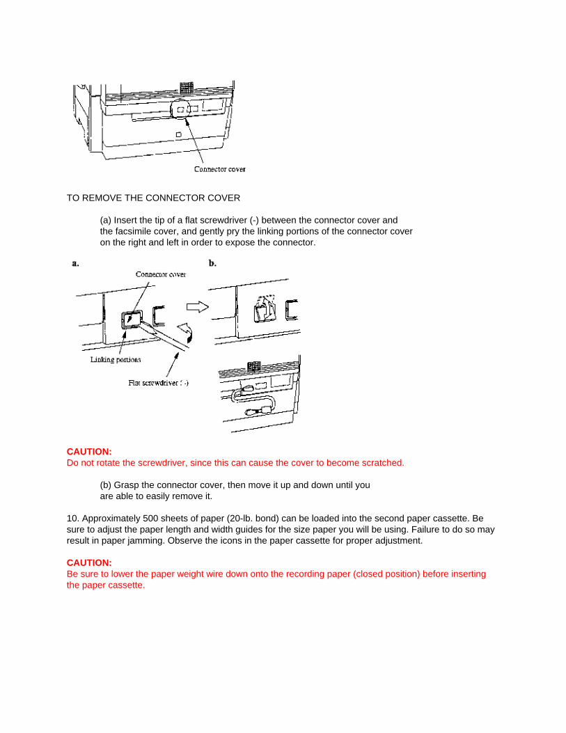
TO REMOVE THE CONNECTOR COVER
(a) Insert the tip of a flat screwdriver (-) between the connector cover and the facsimile cover, and gently pry the linking portions of the connector cover on the right and left in order to expose the connector.
CAUTION:Do not rotate the screwdriver, since this can cause the cover to become scratched.
(b) Grasp the connector cover, then move it up and down until you are able to easily remove it.
10. Approximately 500 sheets of paper (20-lb. bond) can be loaded into the second paper cassette. Be sure to adjust the paper length and width guides for the size paper you will be using. Failure to do so may result in paper jamming. Observe the icons in the paper cassette for proper adjustment.
CAUTION:Be sure to lower the paper weight wire down onto the recording paper (closed position) before inserting the paper cassette.

11. Connect the power cord to the power outlet and the facsimile, and turn the facsimile power switch ON. Your second paper cassette unit is now ready to be used.
Copyright 1997, Okidata, Division of OKI America, Inc. All rights reserved. See the OKIDATA Business Partner Exchange (BPX) for any updates to this material. (http://bpx.okidata.com)

Page: 206
Service Guide OF2200/2400/2600Chapter C Installation of Options
UST-500 Testing Procedure
In order to test the UST-500 for proper operation, you should make a copy of a document.
Okifax 2200When making a copy of a document, the Okifax 2200 automatically selects the paper tray with the correct size paper installed. For example, if you are making a copy of a legal size document and legal size paper is installed in the UST-500 paper tray, the Okifax 2200 will feed paper from the UST-500 paper tray. Of course, the standard tray must have paper other than legal size installed (or be out of paper).
If the UST-500 paper tray contains the same size paper as the standard tray, remove the paper from the standard tray before making a copy.
Okifax 2400/2600The default paper source for the Okifax 2400 and Okifax 2600 is the standard paper tray (regardless of the size document being copied). In order to use the copy mode to test the UST-500 for proper operation, the SECOND TRAY COPY feature must be activated.
To activate the SECOND TRAY COPY feature perform the following.
1. Load the document(s) to be copied in the Automatic Document Feeder.
2. Press the SELECT FUNCTION Key.
3. Press One-Touch Key #32. This key is labeled 2ND TRAY COPY.
The LCD on the operator panel will display:2ND CASSETTE COPY ?[LT] YES ( ) NO ( )
NOTE:The second line of the display indicates the paper size currently loaded in the UST-500.To change the paper size, press the NO Key until the proper paper size appears in the display.
4. To accept the displayed paper size press the YES Key.
You will then be prompted to enter the number of copies desired. After selected the number of copies desired, press the COPY Key to start making copies. If you do not select a copy quantity, copying will automatically start after three seconds.
Copyright 1997, Okidata, Division of OKI America, Inc. All rights reserved. See the OKIDATA Business Partner Exchange (BPX) for any updates to this material. (http://bpx.okidata.com)
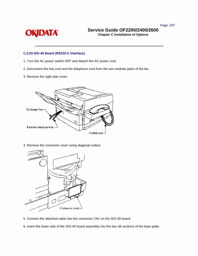
Page: 207
Service Guide OF2200/2400/2600Chapter C Installation of Options
C.2.03 SIO-45 Board (RS232-C Interface)
1. Turn the AC power switch OFF and detach the AC power cord.
2. Disconnect the line cord and the telephone cord from the two modular jacks of the fax.
3. Remove the right side cover.
4. Remove the connector cover using diagonal cutters.
5. Connect the attached cable into the connector CN1 on the SIO-45 board.
6. Insert the lower side of the SIO-45 board assembly into the two slit sections of the base plate.

7. Secure the SIO-45 board assembly into the two slit sections of the base plate.
8. Connect the attached cable into the connector CN4 on the DFCU (MCNT) board.
9. Assemble to right side cover, the rear cover, and the cords by following these directions in reverse order.
Copyright 1997, Okidata, Division of OKI America, Inc. All rights reserved. See the OKIDATA Business Partner Exchange (BPX) for any updates to this material. (http://bpx.okidata.com)

Page: 208
Service Guide OF2200/2400/2600Chapter C Installation of Options
C.3 TELEPHONE ANSWERING DEVICE (TAD) INTERFACE(Pertains to the Okifax 2200 only)
C.3.01 General InformationThe Telephone Answering Device (TAD) Interface allows Okifax units to share the same phone line with a telephone answering device. The Okifax unit and answering device work together to process incoming voice and fax calls, each to their own function. For the TAD Interface to function properly, the following User Functions must be set:
1. TAD Mode (Technical Function #45) must be enabled. The default setting is OFF.
2. Ring Response Time (User Function #24)(User Function #25 when optional High Capacity Cassette is installed) should be set to "1" ring. This is the default setting.
3. Tel/Fax Timer (User Function #10) should be set to 35 seconds. This is the default setting.
To properly connect the Okifax unit to an answering device and phone line, the physical hook-up must be as follows:
1. The line cord from the RJ11C jack should be connected to thejack marked "Line" on the Okifax unit.
2. The answering device must have its line cord connected to the jackmarked "Tel" on the Okifax unit.
NOTE:A single line telephone may then be connected to the jack marked "TEL" or "PHONE" on the answering device, although this is optional.
Once the physical connections have been established and the function settings programmed, the TAD Interface functions as follows:
1. When an incoming call is received, the Okifax will monitor the line for 35 seconds (Tel/Fax Timer setting determines this period). The timing period begins when the first incoming ring is detected. During this time, the Okifax unit listens for two things, and acts on them as follows:
(a) CNG (Calling tone) from a remote fax unit. This 1100 Hz tone is sent by most facsimile units that dial automatically. The Okifax unit will seize the line from the answering device and begin automatic reception if the CNG tone is detected.
(b) The Okifax unit waits for the answering device to disconnect the line. Once the Okifax unit senses that the answering device has dropped the line, it begins automatic reception.
EXPLANATION:Normally, the answering device will answer an incoming call and play its announcement. When the answering device disconnects the line, the Okifax unit will seize the line and attempt automatic reception.

If the remote caller decides to leave a voice message, the Okifax will attempt automatic reception when the caller had completed their message. This gives the remote caller an opportunity to manually send a fax whether or not they decide to leave a voice message.
NOTE:If the answering device does not answer an incoming call within 35 seconds, the Okifax unit will begin automatic reception. It is recommended that the answering device be set to answer incoming calls on as few rings as possible.
There are times that the remote caller may have no intention of manually sending a fax. Because the Okifax 2200 always provides the opportunity for the remote caller to send a fax, the Okifax 2200 begins automatic reception whenever the answering device drops the line. The Okifax will hold the line open for 60 seconds while it attempts to receive.
When the Okifax attempts to receive after an incoming call, the receive tones can be heard through the line monitor. Because the TAD Interface is designed to be used when nobody is available to take phone calls, this would not normally be a problem. In a situation where the user finds the line monitor to be annoying, the volume of the line monitor may be lowered or disabled (User Function #5). Be aware, however, that once the line monitor is disabled, it becomes unavailable for transmit functions.
Copyright 1997, Okidata, Division of OKI America, Inc. All rights reserved. See the OKIDATA Business Partner Exchange (BPX) for any updates to this material. (http://bpx.okidata.com)