oil industry safety directorate इंसुले न प्रणाली का
TRANSCRIPT

Page No. I
DRAFT-II
OIL INDUSTRY SAFETY DIRECTORATE
इंसुलेशन प्रणाली का ननरीक्षण एवं अनुरक्षण ओ आई एस डी-मानक-177
INSPECTION AND MAINTENANCE OF
INSULATION SYSTEM
OISD-STANDARD-177
Prepared by COMMITTEE ON
“Inspection & Maintenance of Insulation system”
FOR RESTRICTED CIRULATION ONLY
OIL INDUSTRY SAFETY DIRECTORATE
Government of India Ministry of Petroleum & Natural Gas
8th Floor, OIDB Bhavan, Plot No. 2, Sector – 73, Noida – 201301 (U.P.) Website: https://www.oisd.gov.in Tele: 0120-2593833, Fax: 0120-2593802
Inception June 1998
Revised edition 2020

Page No. II
PREAMBLE
Indian Petroleum Industry is the energy lifeline of the nation and its continuous performance is essential for growth and prosperity of the country. As the industry essentially deals with inherently inflammable, hazardous and toxic substances throughout its value chain – upstream, midstream and downstream – Safety is of paramount importance to this industry as only safe performance at all times can ensure optimum Return on investment of these national assets and resources including sustainability.
While statutory organizations were in place all along to oversee safety aspects of Indian Petroleum Industry, Oil Industry Safety Directorate (OISD) was set up in 1986 by Ministry of Petroleum and Natural Gas, Government of India as a knowledge centre for formulation of updated world-scale standards for design, layout and operation of various equipment, facility and activities involved in this industry. Moreover, OISD was also given responsibility of monitoring implementation status of these standards through safety audits.
In more than three decades of its existence, OISD has developed a rigorous, multi-layer, iterative and participative process of development of standards – starting with research by in-house experts and iterating through seeking & validating inputs from all stake-holders – operators, designers, national level knowledge authorities and public at large – with a feedback loop of constant updating based on ground level experience obtained through audits, incident analysis and environment scanning.
The participative process followed in standard formulation has resulted in excellent level of compliance by the industry culminating in a safer environment in the industry. OISD – except in the Upstream Petroleum Sector – is still a regulatory (and not a statutory) body but that has not affected implementation of the OISD standards. It also goes to prove the old adage that self-regulation is the best regulation. The quality and relevance of OISD standards had been further endorsed by their adoption in various statutory rules of the land.
Petroleum Industry in India is significantly globalized at present in terms of technology content requiring its operation to keep pace with the relevant world scale standards & practices. This matches the OISD philosophy of continuous improvement keeping pace with the global developments in its target environment. To this end, OISD keeps track of changes through participation as member in large number of International and national level Knowledge Organizations – both in the field of standard development and implementation & monitoring in addition to updation of internal knowledge base through continuous research and application surveillance, thereby ensuring that this OISD Standard, along with all other extant ones, remains relevant, updated and effective on a real time basis in the applicable areas.
Together we strive to achieve NIL incidents in the entire Hydrocarbon Value Chain. This, besides other issues, calls for total engagement from all levels of the stake holder organizations, which we, at OISD, fervently look forward to.
Jai Hind!!!
Executive Director Oil Industry Safety Directorate

Page No. III
FOREWORD
The Oil Industry in India is over 100 years old. As such, various practices have been in vogue because of collaboration/ association with different foreign companies and governments. Standardization in design philosophies, operating and maintenance practices remained a grey area. This coupled with feedback from some serious accidents that occurred in the past in India and abroad, emphasized the need for the industry to review the existing state-of-the-art in designing, operating and maintaining of Oil and Gas installations.
With this in view, the Ministry of Petroleum and Natural Gas in 1986 constituted a Safety Council assisted by the Oil Industry Safety Directorate (OISD) staffed from within the industry in formulating and implementing a series of self-regulatory measures aimed at removing obsolescence, standardizing and upgrading the existing standards to ensure safe operations. Accordingly, OISD constituted a number of functional committees of experts nominated from the industry to draw up standards and guidelines on various subjects.
The earlier document “Inspection and Maintenance of Thermal Insulation” was prepared in June 1998. The advent of new insulating materials, systems and focus on reliability has also necessitated the revision of this standard. The present document on “Inspection & Maintenance of Insulation system", has been prepared by the Functional Committee on “Inspection & Maintenance of Insulation system". This document is based on the accumulated knowledge and experience of industry members and the various national and international codes and practices.
The figures and annexures used in the document are representative in nature.
We, at OISD, are confident that the provisions of this standard, when implemented in totality, would go a long way in ensuring safe operation of the target group of locations.
Needless to mention, this standard, as always would be reviewed based on field level experience, incident analysis and environment scanning. Suggestions from all stake holders may be forwarded to OISD.

Page No. IV
N O T E
Oil Industry Safety Directorate (OISD) publications are prepared for use in the Oil and Gas industry under Ministry of Petroleum & Natural Gas. These are the property of Ministry of Petroleum & Natural Gas and should not be reproduced or copied and loaned or exhibited to others without written consent from OISD.
Though every effort has been made to assure the accuracy and reliability of the data contained in these documents, OISD hereby expressly disclaims any liability or responsibility for loss or damage resulting from their use.
These documents are intended only to supplement and not to replace the prevailing statutory requirements of PESO, DGMS, Factory Inspectorate or any other Government body which must be followed as applicable.
Where ever Acts/ Rules/ Regulation and National/ International Standards are mentioned in the standard, same relates to in-vogue version of such documents.

Page No. V
-------------------------------------------------------------------------------------------------------------------------------------------- In addition to the above, various other experts from the industry contributed in the preparation, review and finalisation of this document.
2nd FUNCTIONAL COMMITTEE
ON
INSPECTION & MAINTENANCE OF INSULATION SYSTEM
(2020)
List of Members
NAME ORGANISATION
LEADER Shri R P Bhan Hindustan Petroleum Corporation Limited ,Mumbai Refinery
MEMBERS Shri Prasenjit Saha Engineers India Limited
Shri Sohan S Alva Mangalore Refinery and Petrochemicals Ltd, Mangalore
Shri K Rajashekar Bharat Petroleum Corporation Limited – Mumbai Refinery
Shri S. K. Yadav Indian Oil Corporation Limited
Shri Shailesh H Oza Reliance Industries Limited- Jamnagar Refinery
Shri A. K. Singh Gas Authority India Limited
Shri Sandipta Nath Hindustan Petroleum Corporation Limited , Visakh Refinery
Shri P V Shankar Bharat Petroleum Corporation Limited – Kochi Refinery
Shri S K Singh Oil and Natural Gas Corporation ,Uran
Shri K. S. Rajak Indian Oil Corporation Limited
Shri Gautam Kumar Das Numaligarh Refinery Limited, Assam
Shri Manish Kumar Pandey Bharat Oman Refineries Limited, Bina
MEMBER CO-ORDINATOR Shri Dharmvir Oil Industry Safety Directorate, Noida (up to Nov. 2018)
Sh. Devendra M Mahajan Oil Industry Safety Directorate, Noida

Page No. VI
1st FUNCTIONAL COMMITTEE
ON INSPECTION AND MAINTENANCE OF THERMAL INSULATION
(1998) NAME DESIGNATION ORGANISATION LEADER SHRI D.C. PATEL, SR. INSP MGR., BPCL REFINERY, MUMBAI MEMBERS SHRI S. NEELAKANTAN SR.MGR (ENGG SERV.) MRL, CHENNAI SHRI L.J. ROHEKAR SR. INSP. MGR., IOC, GUWAHATI REFINERY,
GUWAHATI SHRI M.S. RATHOR SR. INSPN. MGR., HPCL REFINERY, MUMBAI SHRI S. GHATAK CHOUDHARY SIPM, IOC(R&P), SCOPE COMPLEX,
NEW DELHI SHRI S.B. SARKAR MGR, GAIL, LPG PROJECT,
USAR, ALIBAGH SHRI K. NARAYANAN INSP MGR., CRL, COCHIN MEMBER COORDINATOR SHRI A.K. RANJAN, JOINT DIRECTOR(ENGG), OISD, NEW DELHI
------------------------------------------------------------------------------------------------------------------------------------ In addition to the above, various other experts from the industry contributed in the preparation, review and finalisation of this document.

Page No. VII
CONTENTS 1.0 INTRODUCTION 1
2.0 SCOPE 1
3.0 DEFINITION 1
4.0 CLASSIFICATION OF INSULATION SYSTEMS 3
5.0 EXTENT OF INSULATION 4
6.0 HOT INSULATION SYSTEM 5
7.0 COLD INSULATION SYSTEM 9
8.0 ACOUSTIC INSULATION 12
9.0 PERSONNEL PROTECTION SYSTEM 13
10.0 PREVENTION OF CORROSION UNDER INSULATION (CUI) 13
11.0 APPLICATION OF HOT INSULATION 14
12.0 APPLICATION OF COLD INSULATION 19
13.0 INSPECTION & MAINTENANCE OF INSULATION SYSTEM 22
14.0 ABBREVATIONS 29
15.0 REFERENCES 30
16.0 INFORMATIVE ANNEXURES 30

OISD – STD – 177 Page No.1 INSPECTION AND MAINTENANCE OF INSULATION
SYSTEM
“OISD hereby expressly disclaims any liability or responsibility for loss or damage resulting from the use of OISD Standards/Guidelines.”
INSPECTION AND MAINTENANCE OF INSULATION SYSTEM
1.0 INTRODUCTION
The need for effective and efficient insulating system has become more important with increasing energy costs, higher/ lower operating temperature and to enhance reliability & safety of the equipment. The requirement to keep a product at the appropriate temperature is necessary either due to process requirements or to maintain the flow characteristics. Fluids lose/ gain heat energy through metal surfaces in which they are contained or flowing. As this heat loss/ gain leads to inefficiency, methods to minimise these losses/gains need attention. The minimisation of heat loss/ gain can be achieved by judicious application and maintenance of insulation system. Insulation not only serves the purpose of reduction of pressure relief loads in event of fire but also ensures the safety of personnel working with hot/ cold/ high noise equipments/ lines in operating plants.
2.0 SCOPE
This standard lays down the minimum requirement for application, inspection and maintenance for various insulation system such as hot, cold, acoustic and personnel protection on equipment, tanks and piping/ pipelines in oil and gas industry. The standard also covers in brief inspection checks at the time of installation.
3.0 DEFINITIONS
Following are some common terms relevant to insulation systems used in the industry. An attempt has been made in this standard to describe the common terminologies used in the industry as below.
3.1 Blanket Insulation:
A flexible insulating material composed of felt fibrous material with/without binder, but covered by flexible metal mesh facings attached on one or both sides in case of mineral wool insulation.
3.2 Block Insulation:
Segmental blocks of board / semi-rigid slabs of compressed fibrous insulation with or without facing and with or without attachment having regular geometry is known as block insulation.
3.3 Breather coating (applicable for hot insulation):
A weather barrier coating designed to prevent water (rain, spillage, wash water, etc.) entering into insulation system, but allows vapours of water moisture entrapped in the insulation to pass through it. This is usually thick mastic applied by brushing/ towelling (also available in form of wraps).
3.4 Fibrous Insulation:
Insulation materials composed of small diameter fibres woven/ arranged in open cell structure that finely divide the air space. The fibres used are silica, rock wool, slag wool or alumina silica. Insulation constructed from fibre, naturally occurring or manufactured, that incorporates single or composite filaments generally circular in cross section and of length considerably greater than the diameter.

OISD – STD – 177 Page No.2 INSPECTION AND MAINTENANCE OF INSULATION
SYSTEM
“OISD hereby expressly disclaims any liability or responsibility for loss or damage resulting from the use of OISD Standards/Guidelines.”
3.5 Insulating Coating:
Insulating coating is a mastic product which is an alternative to conventional insulation system. It can be used up to operating temperature 175 Deg C (or lower) for personnel protection, prevention of CUI and also used for areas where space is highly restrictive.
3.6 Moisture Barrier (inside surface of metal cladding):
A thin film (typically Polysurlyn) is applied on inner side of the metal cladding with an objective to prevent the metal cladding from being exposed to water/ water vapour from inside thereby reducing the risk of galvanic/ crevice corrosion of the metal jacket.
3.7 Non-Contact Insulation:
Insulation system in which spacers are used to avoid contact between bare surfaces of piping/ equipment and insulation material. The annular space between insulation material and bare surface is not intended to be ventilated, however openings or drains are provided and are located at the lowest point of the piping or equipment and at potential moisture traps.
3.8 Preformed Insulation:
These are essentially block insulations prefabricated in such a manner that at least one surface conforms to the shape of the substrate surface on which insulation is to be applied and such that when applied, will maintain its shape without cracking, breaking, crumbling or permanent deformation.
3.9 Thermal Conductivity:
Thermal conductivity is a measure of ability of a material to conduct heat and defined as quantity of heat flow per unit time (in the steady state) through unit area cross-section of an infinite piece of a material, when unit temperature difference between two planes normal to thermal flux is established between two faces. Lower the thermal conductivity, better is the insulation property of a material.
3.10 Vapour Barrier (applicable for cold insulation):
A thick mastic or film (typically 1 to 1.5mm when dry) applied on outermost insulation surface underneath cladding that significantly impedes the transmission of water vapour under specified conditions used in cold Insulation. This is often called primary vapour barrier. Cold insulation systems will typically have a „primary vapour barrier‟ applied over external surface of the insulation underneath weather barrier jacket (cladding).
A secondary vapour barrier (commonly known as multiplex / Mylar foil) is additionally used for cold insulation systems below minus (-) 50 Deg. C. It is typically a three layer laminated foil (~50-micron thickness) made of aluminium & polyester (~25µ aluminium foil sandwiched between two ~12µ polyester films), applied underneath of outermost insulation layer as additional barrier to prevent moisture coming into insulation in the event of primary vapour barrier failure.
3.11 Vapour stop (applicable for cold insulation):
All cold insulations shall have a „vapour stop‟ across insulation thickness at regular intervals. This is a thick mastic (typically 1 to 1.5mm when dry) applied at insulation terminations on both sides of insulation terminations, for example pipe supports.

OISD – STD – 177 Page No.3 INSPECTION AND MAINTENANCE OF INSULATION
SYSTEM
“OISD hereby expressly disclaims any liability or responsibility for loss or damage resulting from the use of OISD Standards/Guidelines.”
4.0 CLASSIFICATION OF INSULATION SYSTEMS
Insulation systems can be broadly classified into four categories, depending on services, these are Hot insulation, Cold insulation, Acoustic insulation and Personnel protection.
Note: Some service may require insulation system in combination of the above system such as dual temperature service, acoustic with thermal etc.
4.1 Hot Insulation:
Insulation system applied on external surface of the equipment/ piping operating above ambient for heat conservation purpose is termed as "Hot Insulation".
This standard covers the aspects of hot insulation for equipment/ piping operating above 60 Deg. C up to 760 Deg. C with an objective to reduce heat loss / maintain process temperature and / or minimize the risk of corrosion under insulation.
4.2 Cold Insulation:
Insulation system applied on external surface of the equipment/ piping operating below ambient for cold conservation purpose is termed as "Cold Insulation".
This standard covers cold insulation aspects for equipment/ piping operating below ambient up to (-) minus 200 Deg. C with an objective to reduce heat gain/ maintain process temperature and / or avoid condensation at the outer surface.
4.3 Acoustic Insulation:
Insulation applied with an objective to reduce the noise level radiated from a vibrating object/ piping is known as acoustic insulation. Piping connected to valves, compressor, pumps, ejectors etc. which emits high noise are applied with acoustic insulation to reduce noise below an acceptable limit (usually 85 dB).
4.4 Personnel Protection:
Insulation system / screening / barricading / guard provided for the protection of personnel from hot (above 60 Deg C) or cold (below minus (-) 10 Deg C) burn in human approachable area and / or hazardous contact on equipment and piping is termed as personnel protection.
4.5 Combination System:
INSULATION
SYSTEM
HOT
INSULATION
COLD
INSULATION
ACOUSTIC
INSULATION
PERSONNEL PROTECTION

OISD – STD – 177 Page No.4 INSPECTION AND MAINTENANCE OF INSULATION
SYSTEM
“OISD hereby expressly disclaims any liability or responsibility for loss or damage resulting from the use of OISD Standards/Guidelines.”
Additionally, there could be special cases, where insulation is required for dual services, for example cyclic operations. Also, there could be requirements of acoustic insulation together with hot or cold insulation.
4.6 Dual Temperature Insulation:
i. Equipment/ piping exposed to cyclic operations shall require insulation system suitable for both hot and cold services.
ii. Insulation system operating in cyclic services requires special attention for the temperature range of the insulation and auxiliary materials and the effects of temperature changes.
4.6.1 Acoustic & Thermal (Hot / Cold) Insulation:
Where acoustic insulation is a requirement together with hot insulation, the insulation material and cladding meeting acoustic requirements shall be used. Thickness of the insulation shall be the higher of the two requirements. For low operating temperature (for example ambient to 175 Deg C) necessary protection from Corrosion Under Insulation (CUI) such as moisture barrier etc., as applicable for hot insulation system shall also be used.
Where insulation is required for cold and acoustic service, both shall be applied. First the cold insulation system (without cladding, but with primary vapour barrier) shall be applied and then acoustic insulation shall be applied over it.
An additional vapour barrier layer shall be applied to the outside layer of the acoustic insulation underneath metal cladding. The metal cladding should be secured in the same manner a cold insulation cladding is used so that the underneath vapour barrier layer is not punctured (screws rivets etc. which may cause puncture of the underneath layer shall not be used).
5.0 EXTENT OF INSULATION
Extent of insulation shall be as per respective project specification.
In general, when hot insulation is applied, the entire system shall be completely insulated, including all components, such as piping, instrumentation lines, drains, stiffeners, ribs, nozzles, etc., which shall have the same insulation thickness, as indicated in the applicable documents / drawings.
Unless otherwise specified, valves and flange joints in steam, condensate service, hot oil lines and heat traced lines should normally be insulated.
In specific cases, support skirts for high temperature vessels may require insulation.
5.1 Unless otherwise specified, hot insulation shall NOT be applied to the following cases:
5.1.1 Internally insulated or refractory lined equipment unless specially designed for metal temperature control
5.1.2 Piping which becomes hot intermittently, such as relief valves, vents, steam-out and snuffing steam system, flare and blow down systems.
5.1.3 Steam condensate lines downstream of steam traps discharging to drainage system.
5.1.4 Supports for piping, excluding pipe hangers to the extent covered by insulation.
5.1.5 Pipe Union fittings.
5.1.6 Thermo well bosses, temperature and pressure tappings.

OISD – STD – 177 Page No.5 INSPECTION AND MAINTENANCE OF INSULATION
SYSTEM
“OISD hereby expressly disclaims any liability or responsibility for loss or damage resulting from the use of OISD Standards/Guidelines.”
5.1.7 Fans, compressors and blowers
5.1.8 Pumps with operating temperature below 200 Deg C
5.1.9 Expansion joints, hinged joints and hose assemblies
5.1.10 Sight flow indicators.
5.1.11 Flange joints in Hydrogen service.
5.1.12 Valves and flange joints in hydrocarbon service
5.1.13 Turbine casings to be insulated shall exclude shaft seal caps, shaft bearing housings, throttle valves, governors and supports.
5.1.14 Nozzles flanges, manholes, hand holes and flanges of equipment.
5.1.15 Surfaces of coolers and condensers.
5.1.16 Nameplates of all equipment items.
5.2 Cold insulation applied to piping/ equipment shall be extended to all attachments and projections such as structural supports, pipe supports/ hangers, instrument lead lines, branch lines like vents, drains and instrument connections etc.
5.3 Insulation thickness of valves and fittings shall be same as that of the adjoining piping. All flanged joints, manhole covers, etc. shall be insulated with removable box insulation.
5.4 Items like bonnet of valves above the packing glands, display like nameplates, stampings, inspection code etc. should be specially designed and insulated so that the display is not covered by insulation.
5.5 Underground piping for chilled water, hot water, steam traced lines for may require insulation. Insulation material for underground should of rigid non-hydrophobic block insulation like Polyurethane Foam (PUF), cellular glass, moulded perlite etc. Fibrous insulation like rock wool / calcium silicate should be avoided for underground piping or if at all necessary, may be used in combination with PUF such that it remains inside PUF. Selection of material will also depend on operating temperature, type of service - continuous temperature or cyclic, pipe length, diameter, burial depth etc.
Insulation materials in general for the underground services shall have following properties:
Must be hydrophobic in nature
High electrical resistivity preventing galvanic action between metal pipe and the soil
High load bearing properties.
The outer cladding shall be waterproof membrane against most soil and water condition. The typical cladding considered are UV resistant high density polyethylene (HDPE), Glass fibre reinforced polymer (GRP), Glass fibre reinforced epoxy (GRE) or Wapping material consists of three layers of a polymer-modified, bituminous compound separated by glass reinforcement and aluminium foil.
6.0 HOT INSULATION SYSTEM
This section covers hot insulation for equipment like vessels, tanks and piping operating above 60 deg C. to 760 Deg C. Insulation system shall consist of single/ multilayer insulation fixed with

OISD – STD – 177 Page No.6 INSPECTION AND MAINTENANCE OF INSULATION
SYSTEM
“OISD hereby expressly disclaims any liability or responsibility for loss or damage resulting from the use of OISD Standards/Guidelines.”
adhesives, joint sealants, protected from moisture/ water ingress by breather coating and covered with a weather protection jacket.
Hot insulation system has following components:
6.1 Insulating materials for hot service
In general, insulating materials for hot insulation are open cell structure, for example rock wool, glass wool, calcium silicate, ceramic fibre etc. In special condition such as CUI risk zones, cyclic operation etc. material with closed cell like cellular glass, moulded perlite, Polyisocyanurate (PIR), aerogel, insulating coating etc. are used.
Special attention shall be paid for chloride content of insulating materials for use over austenitic stainless steel surfaces.
Common materials used in hot insulation are given below:
6.1.1 Rock wool
i. Rock wool (often called mineral wool) is made from molten mineral rocks by centrifugal spinning process and bonded into slab/mattress (Light Resin Bonded- LRB) or pipe section with a binder.
ii. Mineral wool/ rock wool fibre made from molten basalt rocks is generally stable up to 750 Deg C, but bonded LRB/ pipe sections can safely be used as good insulation material up to 350 Deg C, beyond this, water repellence of the product deteriorates due to binder migration and should be judiciously used. Generally, rock wool insulation is not recommended above 550 Deg C.
iii. Rock wool blanket (metal mesh covered) shall be in accordance with ASTM C592 Type-II/ Equivalent IS/ international standard. Preformed pipe insulation should be in accordance with ASTM C547 Type-II/ Equivalent IS/ international standard. Light resin bonded rock wool fibre block and board shall be in accordance with ASTM C612 Type-IV B/ Equivalent IS/ international standard.
iv. For application over carbon steel, rock wool shall have leachable chloride less than 20 PPM. For use over austenitic stainless steel surfaces, it shall have leachable chloride less than 10 PPM and shall be inhibited with sodium silicate as per ASTM C795/ Equivalent IS/ international standard.
v. In case of application over stainless steel surface, stainless steel metal facings shall only be considered.
HOT INSULATION
SYSTEM
INSULATION MATERIAL
BREATHER COATING
(FOR CUI RISK ZONE)
CLADDING
FLAT SPRINGS ANCILLARY MATERIALS

OISD – STD – 177 Page No.7 INSPECTION AND MAINTENANCE OF INSULATION
SYSTEM
“OISD hereby expressly disclaims any liability or responsibility for loss or damage resulting from the use of OISD Standards/Guidelines.”
6.1.2 Calcium Silicate
i. Calcium silicate block insulation shall conform to ASTM C533 TYPE II /Equivalent IS / international standard, having temperature limit 927 Deg.C, suitable for hot insulation services up to 760 Deg.C.
ii. Calcium silicate is typically used for temperature above 350 Deg C. and/or where foot traffic is expected. Calcium silicate shall have leachable chloride less than 50 PPM.
6.1.3 Glass Wool
i. Glass wool is made from molten glass in form of staple fibre, continuous filaments mattresses on semi rigid bonded slabs. It can be used for insulation on surfaces having temperature not exceeding 500 Deg.C, However, when bonded, the same can be used on surfaces with temperature not exceeding 450 Deg C.
ii. The synthetic resin bonded glass wool slabs with quartz and sand as principal raw material shall be in accordance with ASTM C612 type-II / Equivalent IS / international standard.
iii. For application over carbon steel, glass wool shall have leachable chloride less than 20 PPM. For use over austenitic stainless steel surfaces, it shall have leachable chloride less than 10 PPM and shall be inhibited with sodium silicate as per ASTM C795/ Equivalent IS / international standard
6.1.4 Ceramic Fibres
i. Ceramic Fibre is composed principally of Alumina silica fibre blanket. Ceramic fibre is available in various grades such as 1260 Deg.C, 1425 Deg.C and 1600 Deg.C.
ii. For external insulation over piping/ equipment, up to 760 Deg.C, ceramic fibre of 1260 Deg.C grade is generally used.
iii. Ceramic fibre blankets shall conform to the requirements of ASTM C892 Type III, Grade 8 /Equivalent IS / international standard.
iv. Ceramic fibre shall have leachable chloride less than 50 PPM.
6.1.5 Moulded Expanded Perlite
i. Moulded Expanded Perlite block and pipe sections shall conform to ASTM C610/ Equivalent IS / international standard. It shall be compounded from moulded expanded perlite & binder and should be suitable for temperatures up to 649 Deg.C. The material shall pass the preproduction test method for stress corrosion effects on austenitic stainless steel.
ii. Perlite has good water repellence and can be used for hot insulation services both low as well as high temperatures, up to 649 Deg C.
6.1.6 Cellular Glass
i. Cellular glass shall conform to the classification of ASTM C552, grade 6// Equivalent IS/ international standard, intended for use on surfaces operating temperatures between minus (-) 200 Deg.C to 427 Deg.C. The curved sections shall be fabricated as per ASTM C1639/Equivalent IS / international standard.
ii. It is normally a preferred insulation material for dual temperature service.

OISD – STD – 177 Page No.8 INSPECTION AND MAINTENANCE OF INSULATION
SYSTEM
“OISD hereby expressly disclaims any liability or responsibility for loss or damage resulting from the use of OISD Standards/Guidelines.”
6.1.7 Flexible Aerogel Insulation
i. Flexible aerogel insulation is a composite of an amorphous silica-based aerogel, a fibrous carrying media, or reinforcements, or a combination thereof, that allow the construct to be flexible. The material is available in separate variant for hot and cold service. For hot insulation service, the material shall be in accordance with ASTM C1728, Type-III, Grade-1A/ Equivalent IS/ international standard and should be suitable in the temperature range 24 Deg.C to 649 Deg.C.
ii. The material has low thermal conductivity and has specific advantage of water repellence and preferred in application associated with high risk of CUI and where there is a space constraint.
6.1.8 Insulation materials for impulse lines or small bore lines
Insulation materials for impulse lines should be sodium silicate inhibited ceramic fibre rope. Ceramic fibre ropes should comprise of ceramic fibres (conforming to clause no 6.1.4 of this document) laid parallel and reinforced with stainless steel wire.
6.1.9 Breather coating
i. A breather barrier coat may be used to minimize CUI for hot insulation/ personnel protection for operating temperature in the range of 50 to175 Deg.C where fibrous insulation with metal cladding and conventional paint system is used.
ii. The coating should be applied on outer surface of insulation by brushing/ trowelling underneath metal cladding with glass cloth reinforcement. The mastic turns into a thick film, 1 to 1.5mm when dry. It is also available in form of wraps.
6.1.10 Cladding
Insulation is protected from rain water and weather damage by means of cladding. Both metallic and non-metallic claddings are used in the industry depending on the area/ zone and operating temperatures.
Appropriate cladding (metallic/ non-metallic/ MOC/ grade) shall be selected based on type of insulation, under insulation painting, operating temperature, fire safe criteria etc.
6.1.11 Metal cladding
i. For temperature up to 550 Deg C or unless otherwise mentioned, aluminium jacketing may be used as weather protection cladding. Aluminium cladding shall be polysurlyn laminated on inside surface.
ii. For temperature above 550 Deg C and/ or for fire safe insulation (for all temperature range) cladding should be stainless steel or aluminized steel with moisture barrier film (e.g. Polysurlyn lamination) on inside surface. Moisture barrier film shall be bonded with the metal cladding and should be factory applied.
iii. For grade piping in off-sites (where foot traffic is expected), jacket material should be galvanized steel in case corrosion is not an issue. Galvanized jacketing shall not be used over insulation on or near austenitic stainless steel and/or austenitic nickel steel Piping & Equipment.
6.1.12 Non-metallic cladding
i. For operating temperature 175 Deg C or less, non-metallic UV cured Glass Fibre Reinforced Polyester (GRP) is preferred for CUI prevention. However, GRP is not recommended for fire hazards situation. If TSA is used in place of conventional painting, metal cladding may be used.

OISD – STD – 177 Page No.9 INSPECTION AND MAINTENANCE OF INSULATION
SYSTEM
“OISD hereby expressly disclaims any liability or responsibility for loss or damage resulting from the use of OISD Standards/Guidelines.”
ii. GRP shall serve as weather protection cladding, which is supplied as flexible sheet with a typical thickness of 1.5 to 2 mm, when exposed to sunlight/ UV rays cures to hard laminate. GRP after curing shall be resistant against UV-radiation, acids, caustic and salt solution.
6.2 Ancillary materials
In addition, various ancillary materials are used for fixing of insulation material, sealing the joints. Some ancillary materials are used as barrier material.
List of the ancillary materials is as follows
Flat spring
Securement bands
Seals
Rivets
Self-tapping screws
S and J clips
Quick release toggle
Binding wire
Sacrificial foil
Mineral fibre at Expansion Joint
Joint sealant for metal jacketing
Multiplex foil
Sealing tapes for multiplex foil
Heat Transfer Cement etc.
7.0 COLD INSULATION SYSTEM
This section covers cold insulation for equipment like vessels, tanks and piping operating below ambient to minus (-) 200°C and also suitable for dual temperature services operating between minus (-) 200°C to (+)350°C. Insulation system shall consist of single/ multilayer insulation fixed with adhesives, joint sealants, protected from moisture/ water ingress by vapour barrier, vapour stop and covered with a weather protection jacket.
Cold insulation should have following components:

OISD – STD – 177 Page No.10 INSPECTION AND MAINTENANCE OF INSULATION
SYSTEM
“OISD hereby expressly disclaims any liability or responsibility for loss or damage resulting from the use of OISD Standards/Guidelines.”
7.1 Insulation materials for cold service
Insulation materials for cold service shall essentially be of closed cell structure like cellular glass, PIR, moulded Perlite or special materials like Ethylene Propylene Diene Monomer (EPDM), aerogel etc.
7.1.1 Cellular Glass
Cellular glass shall conform to the classification of ASTM C552, grade 6/ Equivalent IS/ international standard, intended for use on surfaces operating temperatures between minus (-) 200 Deg.C to 427 Deg.C. The curved sections shall be fabricated as per ASTM C1639/ Equivalent IS/ international standard.
7.1.2 Preformed Polyisocyanurate / Polyurethane Rigid Foam (PIR/ PUR)
i. PIR/PUR insulating materials shall generally conform to ASTM C591 Grade-2 Type-II/ Equivalent IS/ international standard, should be supplied pre-shaped in the contour of pipe section / equipment or cut into required shapes from buns (blocks) at site using appropriate machine.
ii. Pipe sections should be made from buns made in continuous production and then machine cut into pipe sections using a CNC machine. For small diameters, pipe sections should be fabricated in two halves, for larger diameter multiple sections may be used with radial joints not exceeding four. For operating temperature up to minus (-) 50 Deg.C, moulded PIR sections may be used.
iii. For valves, flanges requiring cold insulation, in-situ foaming is also an option. It is a two component liquid, spray applied to form rigid cellular polyurethane foam. Blowing agents containing CFC‟s or HCFC‟s shall not be used.
7.1.3 Flexible Elastomeric Cellular Insulation
Flexible Elastomeric cellular insulation shall generally conform to the ASTM C534/Equivalent IS / international standard, intended for use on surfaces operating temperatures between minus (-) 183 Deg.C to 175 Deg.C.
7.1.4 Perlite granules
COLD INSULATION SYSTEM
INSULATION MATERIAL
VAPOUR BARRIER,
JOINT SEALANT ETC.
CLADDING
PIPE
SUPPORTS
OISD – STD – 177 Page No.11 INSPECTION AND MAINTENANCE OF INSULATION
SYSTEM
“OISD hereby expressly disclaims any liability or responsibility for loss or damage resulting from the use of OISD Standards/Guidelines.”
Perlite granules consisting of expanded Perlite shall be in accordance with ASTM C549/Equivalent IS / international standard. Expanded perlite granules shall meet the grain size distribution as per ASTM C136/ Equivalent IS/ international standard.
7.1.5 Flexible aerogel Insulation
Flexible aerogel insulation is a composite of an amorphous silica-based aerogel, a fibrous carrying media, or reinforcements, or a combination thereof, that allow the construct to be flexible. The material shall be in accordance with ASTM C1728, Type-I, Grade-1B/Equivalent IS / international standard and should be suitable for temperature range minus (-) 196 Deg.C to 125 Deg.C.
7.1.6 Expanded Polystyrene
The insulation material should be self-extinguishing with closed cell structure in accordance with IS 4671 type SE/ Equivalent IS/ international standard. These materials are prepared from styrene homopolymer or copolymer containing an expanding agent. They can be applied to cold surfaces with temperatures not below minus (-) 195 Deg.C.
Vapour barrier, vapour stop & other ancillaries
i. All cold insulations shall have a thick mastic coating as „primary vapour barrier‟ applied over external surface of the insulation underneath weather barrier jacket (cladding).
ii. Insulation below minus (-) 50 Deg.C, shall have an additional membrane layer ~50 micron as secondary vapour barrier between the outermost layer and next insulating layer.
iii. All cold insulations shall have a „vapour stop‟ across insulation thickness at regular intervals. This is a thick mastic (min 1mm when dry) applied at insulation terminations, for example at both sides of pipe supports.
7.1.7 Primary Vapour Barrier
i. Primary vapour barrier should be fire retardant, compatible with base insulation, stable in the range of minus (-) 40 to 100 Deg. C (e.g. chlorosulfonated polyethylene rubber based elastomeric polymer mastic). Material when dry, should have adequate elasticity and not have any crack or flaking.
ii. The mastic shall be applied in two coats reinforced with glass fibre cloth (approx. at centre of the coating). The coating shall be applied in two coats to appropriate wet thickness to obtain the specified dry film thickness. When cured, the layer should be durable and have good dry film strength and puncture resistance.
7.1.8 Secondary Vapour Barrier
Secondary vapour barrier should be a three layer laminated foil made of aluminium & polyester.
7.1.9 Vapour Stop
i. Vapour stop should be compatible with base insulation, suitable in the range of minus (-)196 to (+) 120 Deg C (e.g. two pack butyl rubber based elastomeric mastic). Material when dry, shall have adequate elasticity and not have any crack or flaking.
ii. The mastic shall be applied in two coats reinforced with polyester coated glass cloth (suitable for cryogenic service) to obtain typical 1mm dry film thickness. When cured, the layer should be durable, have excellent resistance to moisture/ water vapour
7.1.10 Cladding

OISD – STD – 177 Page No.12 INSPECTION AND MAINTENANCE OF INSULATION
SYSTEM
“OISD hereby expressly disclaims any liability or responsibility for loss or damage resulting from the use of OISD Standards/Guidelines.”
Aluminium, galvanized (GI) steel, aluminised steel, UV cured GRP or stainless steel cladding shall be used as weather protection jacket over insulation. In case of Fire safe insulation, only stainless steel cladding shall be considered.
Appropriate cladding (metallic/ non-metallic/ MOC/ grade) shall be selected based on type of insulation, under insulation painting, operating temperature, fire safe criteria etc.
Metal cladding wherever used shall have polysurlyn lamination on inside surface.
7.2 Ancillary materials:
In addition, various ancillary materials are used for fixing of insulation material, sealing of the joints, supports etc.
List of the ancillary materials is as follows:
Adhesive
Joint sealant for insulation blocks
Joint sealant for metal cladding
Materials for Contraction Joint
Glass Cloth / Fabric
Adhesive Synthetic Tape
Bands
Pipe supports etc.
8.0 ACOUSTIC INSULATION SYSTEM
Acoustic insulation can be described as an insulation system with heavy cladding, applied to vibrating object/ piping with an objective to reduce the noise level. Piping connected to valves, compressor, pumps, ejectors etc. which emits high noise are applied with acoustic insulation to reduce noise below an acceptable limit (usually 85 dB).
Acoustic insulation system shall essentially consist of a sound absorbing / resilient fibrous material (e.g. rock wool) and impermeable outer cover (metal cladding).
8.1 Some definitions relevant to acoustic insulation
Acoustic class A predefined insulation system consisting of sound absorbing / resilient material (rock wool/ glass wool/ ceramic fiber) and impermeable outer cover (cladding) with defined minimum insertion loss across frequency spectrum of the noise
Noise level dB(A)
Cumulative of A-weighted average of sound radiated across the octave band spectrum, expressed in decibel dB(A)
Loudness of the sound in decibels dB(A) can be expressed in terms of sound pressure level measured at specified location with respect to sound source or in sound power (cumulative of sound pressure across the pipe length). In this

OISD – STD – 177 Page No.13 INSPECTION AND MAINTENANCE OF INSULATION
SYSTEM
“OISD hereby expressly disclaims any liability or responsibility for loss or damage resulting from the use of OISD Standards/Guidelines.”
specification, sound is expressed in power level.
Sound spectra Frequency distribution of the sound in decibels (dB) at different frequency (Hz) across octave band of the sound
Insertion loss Difference in sound power in decibels dB(A) across the octave band (frequency spectrum) before and after application of the acoustic insulation
8.2 Acoustic class
Insulation systems have pre-defined insulation type, thickness and a mass loaded cladding sheet – known as Acoustic Class. The insertion loss (reduction in noise level) of an acoustics depends on the original noise level and frequency distribution of the noise. It is therefore necessary to have the original noise level and frequency distribution to be able to select the most appropriate acoustic class for the application.
Various acoustics classifications are known to exist. Unless otherwise specified, ISO 15665 acoustic insulation systems may be used, in which three acoustic classes are defined such as Class-A, B and C. Each class shall have specified minimum insertion loss across frequency spectrum of the noise.
The original noise level will respond differently based on its frequency distribution, when a particular acoustic class (for example Class-A, B or C if ISO 15665 is followed) is applied. The insertion loss for each acoustic class should be calculated separately and the most effective class shall be selected.
9.0 PERSONNEL PROTECTION SYSTEM
Insulation system / screening / physical barrier provided for the protection of personnel from hot (above 60 Deg C) or cold (below minus (-) 10 Deg C) in human approachable area and / or hazardous contact on equipment and piping is termed as personnel protection. This insulation is not a process requirement.
Personnel protection can be provided by means of
Insulation
Barrier (Metal guards)
Painting (Insulation coating)
In order to minimize risk of corrosion, Insulation for personnel protection at low temperature (60 to 175 Deg C, in cyclic service) should be avoided as far as possible and alternative barriers (metal guards) or insulation painting may be adopted.
9.1 Protection guard system (for personnel protection)
OISD – STD – 177 Page No.14 INSPECTION AND MAINTENANCE OF INSULATION
SYSTEM
“OISD hereby expressly disclaims any liability or responsibility for loss or damage resulting from the use of OISD Standards/Guidelines.”
Metallic guard / cage protection as personal protection insulation should be considered for temperature up to 250°C, above which conventional insulation system with respect to service temperature limitation should be considered.
9.2 Insulating paint system (for personnel protection)
Insulating coating is a water based acrylic or epoxy spray applied coating, it contains engineered composite of ceramic/ silica.
Instead of conventional insulation, insulating coating can be used for personal protection insulation up to temperature 175°C, which will limit the problem relating to CUI.
10.0 PREVENTION OF CORROSION UNDER INSULATION (CUI)
Corrosion under insulation (CUI) is a common problem associated with insulation and caused by water ingress into insulation. It has been recognized within industry that carbon steel operating in the range of minus (–) 12 Deg. C to 175 Deg. C has the greatest likelihood of CUI.
The risk of CUI is maximum at temperature range of 50 Deg. C to 175 Deg. C, equipment / piping which operate in cyclic temperature and when the equipment is idle. Proper attention must be paid for the selection of appropriate paint and insulation system in the CUI risk temperature zone.CUI can be prevented/ minimized in following ways:
Select appropriate painting/ TSA, insulation and cladding with respect to operating temperature
Non-contact insulation
Use of guard, insulating paint or no insulation for personnel protection
Use of breather mastic for CUI risk zone
Insulation materials are of two types as far as texture is concerned. Some materials are open cell structure and fibrous in nature (e.g. mineral wool, calcium silicate ceramic fibre etc.). These are very effective insulation material, have very low thermal conductivity, but all of them absorb and retain moisture to varying degree and promote corrosion under insulation. These materials as far as possible should be avoided in CUI risk zone or to be used with appropriate moisture retarding system or with appropriate paint / TSA to minimize the risk of corrosion.
Insulation materials in the CUI risk zone should be selected from a closed cellular structured material like flexible elastomeric foams, cellular glass, PIR etc. Materials with hydrophobic properties like silica aerogel flexible blanket, expanded perlite etc. could also be a good alternative in CUI risk zone.
In addition to water absorption, another factor to consider is the chemical content of the insulation. It shall be inert, containing no chemicals that would contribute to corrosion or Chloride stress corrosion cracking (Cl-SCC). This aspect is taken care by limiting chlorides in the insulation material.
Painting under insulation plays a great role in prevention of CUI. Appropriate paint must be selected based on operating temperature and insulation system being used.
A typical conventional paint system recommended for units and offsite for insulated piping, equipment, storage vessels, tanks, columns etc. of CS, LTCS, alloy steel & stainless steels in all environments is given as informative annexure 5.
11.0 APPLICATION OF HOT INSULATION

OISD – STD – 177 Page No.15 INSPECTION AND MAINTENANCE OF INSULATION
SYSTEM
“OISD hereby expressly disclaims any liability or responsibility for loss or damage resulting from the use of OISD Standards/Guidelines.”
Effectiveness and better operational life of an insulation system depends on the way it has been installed. An improper installation may not only lead to higher heat losses and reduced life, but also it may lead to corrosion of insulated surfaces. Following minimum standards are recommended for installation of insulation on equipment, storage tanks and pipelines.
11.1 Surface preparation and paint application
The surface to be insulated shall be cleaned thoroughly and painted as per applicable specification, based on service conditions, metallurgy and environment.
11.2 Fixing of Insulation
Insulation shall be properly held in position by support lugs and/ or supporting rings at suitable intervals. Binding / strapping materials like binding wire or band strips are to be used for proper fixing of the insulating material.
11.2.1 Blanket Insulation:
Blanket Insulation mattresses are wrapped on the surface to be insulated and then tied with wires / bands to be held in position. After wrapping blanket on surface and positioning it correctly, the joining end, circumferential as well as longitudinal, should be closed by stitching using SS wire.
After blankets are stitched up in position, a SS wire shall be helically wrapped / banded over it and tightened suitably. This is to give extra strength and uniform shape to the blankets.
11.2.2 Preformed/Fabricated Sections:
Preformed shapes shall fit snugly to the surfaces and should butt closely to each other. Joints shall be staggered and gaps or cavities avoided by trimming the insulation to fit. Where this is not practical, loose-fill or trowelled-in material having comparable thermal insulation properties to the main material shall be used.
Where shown to be more economical or technically advantageous, the insulation should consist of two or more layers of dissimilar materials, provided their respective temperature limits are appropriate for the duty. In multi-layer insulation, individual layer shall be secured by banding, wires or by self-adhesive tapes and all longitudinal and circumferential joints shall be staggered.
11.3 Fixing of Cladding
11.3.1 All the joints (longitudinal & circumferential) shall have sufficient overlap after wrapping of outer cover sheet. The overlap shall be arranged to shed water at all times. The minimum overlap is 50 mm for piping insulation and 80 mm for vessel insulation. In case of corrugated cover sheets, the overlap shall at least be one corrugation on vertical joint and 80 mm on horizontal joints.
11.3.2 Sheet shall be fixed using self-tapping screws and using rivets if fixed to insulation support
11.3.3 In vertical equipment and storage tanks, outer cover sheets shall be provided in such a way so as to avoid ingress of water at the joints.
11.3.4 Outer cover sheets provided on equipment shall have their joints in such a manner so as to avoid ingress of water into the insulation.
11.3.5 End covers shall be provided at the end of insulation.
11.3.6 The joints of metal cladding shall be overlapped in a direction to avoid water ingress into the insulation. Horizontal cladding joints between 10 to 2 o‟clock position shall be avoided

OISD – STD – 177 Page No.16 INSPECTION AND MAINTENANCE OF INSULATION
SYSTEM
“OISD hereby expressly disclaims any liability or responsibility for loss or damage resulting from the use of OISD Standards/Guidelines.”
11.3.7 All openings and joints should be properly sealed with mastic to prevent ingress of water.
11.3.8 After application of insulation the joints & extreme ends of the weather protectors are to be sealed properly with mastic / elastomeric sealant to avoid ingress of water into the insulation.
11.4 Inspection window
Removable plug type inspection window should be provided on the thermal insulation metal jacketing to facilitate the inspection of substrate. Provision of Inspection window shall only be considered for hot service. In cold service no inspection window shall be provided.
Plug flange should be fixed by screws and washers to outside metal jacketing and same shall be sealed for a perfect watertight assembly.
11.4.1 Inspection window position for equipment thermal insulation
i. All the heads of horizontal and vertical equipment/ vessel shall have minimum one inspection window.
ii. The shell of horizontal vessel shall have at least 1 (one) inspection window in every 2 (two) meters of length. The windows should preferably be staggered 180° apart. A minimum of 2 (two) inspection windows are recommended in a vessel shell.
iii. In case of vertical vessels, a minimum of 2 (two) inspection windows preferably 180° apart shall be provided on every platform level.
11.4.2 Inspection window position for piping
i. Inspection windows should be preferably provided at bottom i.e. 4-6-8 O‟ clock position whichever is convenient.
ii. There shall be at least 1(one) inspection window in every 20m length of the straight pipe subject to minimum of 1(one) point every straight length of piping.
iii. There shall be at least 1(one) inspection window between 2 (two) bends which are minimum 10 (ten) meters apart.
iv. Location shall be at least 6‟‟ distance from fitting where changes in direction occur.
v. Whenever line changes its direction, it is considered a new part and should have inspection window.
vi. Pipes NPS 8‟‟ and below: 2 (two) points (at 4-10 or 6-12 or 2-8 O‟ clock position).
vii. Pipes NPS above 8‟‟: 4 (four) points (at 1-4-7-10 or 3-6-9-12 or 2-5-8-11O‟ clock position).
viii. Bends and Elbows NPS 6‟‟ and below: 1 (one) inspection window outside axis in proximity of changing direction.
ix. Bends and Elbows NPS 8‟‟ to 18‟‟: 1 (one) inspection window at 45°.
x. Bends and Elbows NPS above 18‟‟: 2 (two) inspection windows, 1 (one) at 30° and 1 (one) at 60°.
11.5 Insulation Procedure for specific carbon steel equipment / components
Special care as given below should be taken during insulation on the following:
11.5.1 Pipes/ Elbows & Tees

OISD – STD – 177 Page No.17 INSPECTION AND MAINTENANCE OF INSULATION
SYSTEM
“OISD hereby expressly disclaims any liability or responsibility for loss or damage resulting from the use of OISD Standards/Guidelines.”
i. For Preformed Fibrous Insulation (Rigid insulation), the insulation shall be carried out with the least number of material pieces as possible. The longitudinal joints between the two segments should be staggered.
ii. All the circumferential joints shall be closely fitted and the gap, if any, shall be filled with similar insulating material.
iii. The insulation should be fastened using galvanised steel / Stainless Steel wire and/or strapping bands at suitable intervals. A band shall be fastened at suitable distance from either end. The ends of the binding wire shall be tightly twisted together, bent under and pressed into the surface of insulation. Strapping bands should be crimped suitably.
iv. In the case of Flexible Fibrous insulation, the blankets, cut to adequate size, shall be applied with the galvanised / Stainless Steel chicken wire netting on the outside and be fastened into position with galvanised wire.
v. The chicken wire mesh should be stitched on to one side of insulation blankets with annealed galvanised / Stainless Steel wire.
vi. On horizontal lines, loose support rings with stays of Carbon Steel shall be attached to the pipe at suitable intervals to support the outer cover sheets and to prevent sagging of the insulation. On vertical piping or piping inclined at more than 45 0 from the horizontal and where straight runs are in excess of 3mtr., an insulation support shall be provided in form of a metal ring or part ring either clamped or welded to the pipe. Alternatively, angle studs may be used to prevent downward displacement of the insulation. Support shall be located at the bottom of run and thereafter at suitable interval.
vii. For Preformed/Flexible Insulation on Elbows and Bends, Insulation material shall be mitered and should be same as that applied on pipe. Each mitered section should be suitably secured with wires/bands. In the case of Preformed/Flexible Fibrous Insulation on Tees, the Insulation material shall be same as that applied on pipe. Preformed pipe sections/flexible mattress shall be carefully cut and shaped around “Tee” junctions and applied to the parent pipe without the creation of voids and gaps at the junction. Insulation should be adequately secured by wire/band.
viii. Insulation at solid welded or clamped supports shall be cut and shaped to fit around the support and bonded securely.
11.5.2 Steam / Electric Traced Lines
i. The steam tracing that are used with mainlines shall be held in position. The pipe and steam tracer should then be wrapped with a galvanised hex chicken wire mesh/Aluminium foil / heat transfer cement and bound with galvanised / Stainless Steel wire at suitable intervals.
ii. The insulating material, cut to adequate size, shall be provided with the galvanised / Stainless Steel chicken wire netting on the outside. Cladding cover shall be then provided and suitably fastened.
iii. The exposed section of the steam tracer that is not required to be in touch with main line should be wrapped using ceramic fibre rope, the winding should be tight with no gap. The grooves and notches should be filled with quick setting plaster. After drying of plaster, suitable weather proofing coat should be applied.
iv. In case of electric traced lines, due precautions should be taken while fixing the junction Box position to avoid water ingress.

OISD – STD – 177 Page No.18 INSPECTION AND MAINTENANCE OF INSULATION
SYSTEM
“OISD hereby expressly disclaims any liability or responsibility for loss or damage resulting from the use of OISD Standards/Guidelines.”
11.5.3 Small Bore Lines
The small bore lines should be wrapped using ceramic fibre rope / insulation. In case of ceramic rope, the winding shall be tight with no gap and aluminium foil /mastic should be used for weather proofing.
11.5.4 Flanged Joints and Valves
i. Flanged joints and Valves should be insulated with prefabricated removable aluminium covers, lined with preformed/flexible fibrous wool insulation. The insulation should be carried out after commissioning and hot bolting of the system. Care shall be exercised to seal the gaps from where rain water may ingress.
ii. In case of valves, the stuffing box should be kept outside to replace the packing without damaging insulation. Valve body can also be covered with e-glass fibre readymade jacket.
11.5.5 Horizontal Equipment
The vessel shall be provided with insulation support at the horizontal centre line and ring support at radial lines. The insulation supports shall be designed to prevent the channelling and entrapment of the water. These supports should have anchors for insulation securement. Both the dish end heads may be provided with a suitable ring made of steel rod for insulation securement.
When preformed insulation is used, the insulation shall be applied with the longer dimension parallel to the axis of the equipment. Where the total thickness of the slab exceeds 75 mm, multilayer should be used and no layer should exceed 75 mm in thickness. When blocks are applied in multiple layers, all joints in successive layers should be parallel to the long axis and staggered between 3 O‟clock and 9 O‟clock position. The gaps, if any, should be filled with insulating material.
11.5.6 Vertical Equipment
The vessel shall be provided with suitable insulation supports for insulation securement. The insulation support on vessels shall be spaced to suit the standard size of insulation but in no case shall exceed 3 m vertical pitch.
The insulation shall be applied on the shell, top and bottom in similar manner as described for horizontal equipment. Care shall be taken while designing insulation and its support for bottom dish end.
11.5.7 Pumps, Compressors, Turbines & Irregular Surfaces
These shall be insulated with portable removable type aluminium/steel boxes lined with suitable insulation.
11.5.8 Flanged Nozzle, Exchanger Channels/Covers, Manway etc.
These parts should be insulated with removable prefabricated covers lined with preformed fibrous/flexible insulation and secured suitably.
Insulation shall be stopped short of uninsulated flanges and nozzles etc., by leaving a sufficient distance to permit withdrawal of bolts without affecting the remainder of the insulation. Insulation shall be weather proofed and sealed. The insulation should be carried out after commissioning and hot bolting of the system.
11.5.9 Vertical Storage Tanks

OISD – STD – 177 Page No.19 INSPECTION AND MAINTENANCE OF INSULATION
SYSTEM
“OISD hereby expressly disclaims any liability or responsibility for loss or damage resulting from the use of OISD Standards/Guidelines.”
Vertical storage tanks shall be provided with insulation supports. The insulation should be applied between rings in horizontal mode. Mattress insulation shall be applied with joints tightly butted and laced together with galvanised / Stainless Steel lacing wire. The outside of the insulation should have a galvanised / Stainless Steel chicken wire netting stitched on to one side of insulation blankets. To prevent wicking action, bottom of the shell shall be insulated with closed cell insulation like cellular glass typically for 300 to 500 mm height.
Corrugated Aluminium sheet shall be used for tanks shell and flat sheet should be considered for roof head. The protective sheeting is to be further fastened by application of strapping bands externally over it.
Tanks can also be insulated using prefabricated panel insulation system. In this system, insulation slabs are prefixed with the cladding in panel form which are tightly held with the tank by metallic wire rope and does not require insulation cleats for installation.
11.5.10 Special care for Stainless steel equipment / components
Austenitic and duplex stainless steels are prone to chloride stress corrosion cracking in the temperature range of 60°C to 205°C. A barrier layer of stainless steels / Aluminium foil shall be placed between metal surface and insulation. Aluminium foil may be used up to 400 Deg C in non-fire hazardous area. Above 400 Deg C and / or in fire hazardous area stainless steels foils shall only be used to avoid risk of Liquid Metal Embrittlement (LME).
Only materials that contain less than 10 PPM of Chlorides for Rock wool and 50 PPM for Calcium Silicate or Ceramic Fibre shall be used over stainless steel surfaces.
11.5.11 Tank Trucks
Mobile tank truck vessel shall be provided with insulation supports at the horizontal center line and ring supports circumferentially. 'L' Shaped lugs shall be welded to the tank shell for supporting the circumferential rings and providing additional supports in longitudinal direction, in addition the provision of long lugs of appropriate size welded at suitable intervals on either side to hold the insulation.
Insulation blanket of suitable thickness shall be then impaled through the lugs. The entire insulated area is then covered with GI wire netting. In order to prevent conduction between L-lugs and the circumferential rings, asbestos miller board of required thickness to be provided. Finally, the outer cover sheet of aluminium is to be provided and fixed in position. Care shall be taken that all grouped lap joint of cladding shall face downwards and sealed to avoid ingress of water into the joint.
12.0 APPLICATION OF COLD INSULATION
12.1 Surface Préparation & Paint application
The surface to be insulated shall be cleaned thoroughly and painted as per applicable specification. based on service conditions, metallurgy and environment.
12.2 Insulation Fixing Procédures
Follow specific instruction provided by insulation manufacturer for PUF, Cellular Glass or other specific materials
In general, slabs of suitable width cut longitudinally with notch of suitable size, shall be placed at proper spacing so as to form a radial segment to match with the profile of the equipment. All

OISD – STD – 177 Page No.20 INSPECTION AND MAINTENANCE OF INSULATION
SYSTEM
“OISD hereby expressly disclaims any liability or responsibility for loss or damage resulting from the use of OISD Standards/Guidelines.”
insulation joints to be sealed with joint sealer. When more than one layer is applied, each layer should be bonded separately, with applicable adhesive. The joint sealer shall be applied to ends, edges of all sections, including those in the inner most layer to seal all joints. All the layers except the final layer should be secured in position by metallic bands at suitable intervals. The final layer to be secured by metallic bands. All the cracks/voids have to be filled up with applicable filler material.
12.3 Application of primary vapour Barrier :
12.3.1 All cold insulation shall essentially have a thick mastic coating (min 1.5mm when dry) as „primary vapour barrier‟ applied over external surface of the insulation underneath weather barrier jacket (cladding). The mastic should be applied in two coats reinforced with glass fibre cloth to obtain the specified dry film thickness.
12.3.2 Primary vapour barrier mastic should be supplied in two sheds. One shed should be used for the first coat and the other shed for second coat. The first coat should be applied to a wet thickness that contributes half of the required thickness by method as may be specified by the supplier to a smooth finish by covering the insulation joints. At insulation terminations, including those at flanges, the primary vapour barrier should extend at least 75 mm beyond the edges of the insulated section onto adjacent uninsulated equipment/ piping.
12.3.3 The fabric (glass cloth) should be embedded in the wet tack layer such that no wrinkles are formed and all joints have a minimum overlap of at least 50 mm. Apply the second coat (of other shed) after a time gap recommended by the mastic supplier to a smooth finish fully embedding the fabric and to the required thickness to obtain required DFT.
12.3.4 When cured, the layer should be durable and have good dry film strength and puncture resistance. The total dry layer thickness shall conform to the layer thickness specified by the supplier. There shall not be any cracks, holes, thin spots or open joints in the vapour barrier, which should be applied such that no part of the insulation material is uncovered. The connections with protrusions and in corners should be carefully finished
12.4 Application of secondary vapour barrier :
At an operating temperature of -50°C or below, in addition to primary vapour barrier, the multiplex foil as a secondary vapour barrier should be applied between the outermost layer and the next insulation layer. The foil should be cut to size correctly and should be installed with dots of adhesive at the surface, tightly stretched and without air inclusions. The joint should be sealed with multiplex tape of aluminium/polyester.
12.5 Application of Expansion/Contraction joints
When specified on a pipe line or vessel drawing or where deemed necessary to allow movement and contraction of the pipe or vessel without producing random cracking of the insulation, contraction joints should be provided in the insulation. At contraction joint location, provision shall be made in aluminium cladding to accommodate contraction of pipe or vessel.
12.6 Fixing of Cladding
12.6.1 Appropriate metal cladding system shall be selected depending upon the requirement. The metal cladding shall be constructed such that any condensation (moisture) can drain from the cladding. The cladding is fastened with stainless steel bands.

OISD – STD – 177 Page No.21 INSPECTION AND MAINTENANCE OF INSULATION
SYSTEM
“OISD hereby expressly disclaims any liability or responsibility for loss or damage resulting from the use of OISD Standards/Guidelines.”
12.6.2 All the joints (longitudinal & circumferential) shall have sufficient overlap after wrapping of outer cover sheet.
12.6.3 All longitudinal and circumferential joints of metal sheeting shall be sealed with suitable approved non-hardening elastomeric mastic sealer
12.6.4 For horizontal vessel and piping all the longitudinal joints with overlap shall be kept below the horizontal plane passing through the axis of the vessel to prevent water or other spillage from entering into the insulation. At horizontal piping, in the middle between two supports, at the lowest point, drain holes shall be provided, min 1 hole / 6 m, 10mm dia. and at the lowest point of vertical bends, connections etc.
12.6.5 Cladding provided on equipment should have their joints in such a manner so as to avoid ingress of water into the insulation.
12.6.6 End covers should be provided at the end of insulation.
12.7 Insulation procedure for Specific Equipment / components
Special care should be taken during installation of the following:
12.7.1 Vertical vessels – Top heads:
Slab insulation sections to be installed on top head, bonded and butted tightly to each other. Insulation shall be held in position by use of suitable supports. The insulation should be held in position by use of the radial metallic bands, one end of which should be fastened to the floating ring and the other end shall be anchored to the bands placed around the cylindrical section close to the head. Radial bands should be properly spaced measured around the circumference of the vessel.
12.7.2 Vertical vessels – Bottom heads:
i. In all the skirt supported vessels, insulation supports are provided inside the skirt.
ii. Suitable supports around the nozzle and bends should be used to support downward falling of insulation.
iii. It the nozzle is not existing, metallic bands to be stretched across the bottom head and anchored with lagging support angle ring inside the skirt.
iv. Cladding jacket shall be secured in position by radial tensioned metallic bands anchored suitably.
v. Openings in metal jackets for nozzles, man ways, brackets etc. should be cut as close as possible for a snug fit. Sufficient space should be provided for maintenance of flanges.
12.7.3 Horizontal Vessels
Care should be taken to keep all the longitudinal joints in the aluminium sheet below the horizontal plane passing through the axis of the vessel to prevent water or other spillage from entering into the insulation.
Openings in metal jackets for nozzles, manways, brackets etc. should be cut as close as possible for a snug fit.

OISD – STD – 177 Page No.22 INSPECTION AND MAINTENANCE OF INSULATION
SYSTEM
“OISD hereby expressly disclaims any liability or responsibility for loss or damage resulting from the use of OISD Standards/Guidelines.”
12.7.4 Spherical Vessels
i. Insulation to be applied shall be shaped according to the contour of the sphere and bonded to the vessel with applicable adhesive.
ii. All insulation joints should be sealed with joint sealer. The inner layer of insulation should be held in position by aluminium bands. These bands are tied up with the floating rings made of SS rod at the top & bottom of the sphere. The bands shall be staggered at successive layers and the clips of the bands recessed into the insulation. Over the outermost layer galvanised wire netting shall be spread over and laced together.
iii. Aluminium cladding of each hemisphere of spherical vessel should be done with aluminium sheets placed horizontally and a thick circumferential tensioned band shall be used at the equator to hold the radial metallic bonds.
12.7.5 Heat Exchangers
Heat Exchanger shells shall be insulated exactly in the same manner as indicated for the vessels. Only exchanger channels, channel covers including flange bolting shall be insulated with removable aluminium covers lined with insulation slabs of required thickness.
12.7.6 Machinery
In general, wherever cold insulation is required, aluminium boxes lined with slab insulation of adequate thickness shall be used for insulation of machinery after giving a coat of anticorrosive paint.
12.7.7 Horizontal Piping:
Application of cold insulation methods are same as indicated for horizontal type vessel shells. Insulation of piping shall be stopped short of flanges to allow for withdrawal of bolts for maintenance. For pipe fittings, the insulation shall be completed by applying cut segments of the same insulation sections used for pipes. For long run pipes, the ends of insulation section should be sealed off at proper intervals and vapour barrier to be carried out up to the metal surface at the point of sealing. Contraction joint shall be provided at proper intervals.
12.7.8 Vertical Piping
The procedure is same as indicated for horizontal piping. Only insulation supports/spacer rings be provided at adequate intervals.
12.7.9 Pipe Supports and Hangers
In all the supporting arrangements of both horizontal and vertical piping, high density PUF support bearing blocks shall be used. Metal cradles, metal pipe supports, hangers shall be attached to outside of the pipe support bearing blocks and not directly to bare pipe. Provision to be made to prevent seepage of water into the insulation from pipe hangers.
12.7.10 Flanges and Valves
Removable type covers should be provided over all flanges and valves. These covers should be fitted with quick release clips.
12.7.11 Stainless Steel Piping and Equipment
All pipes, vessels and equipment of stainless steel construction to be painted and wrapped with aluminium foil (moisture barrier) or stainless steels foil with adequate overlap having sealer

OISD – STD – 177 Page No.23 INSPECTION AND MAINTENANCE OF INSULATION
SYSTEM
“OISD hereby expressly disclaims any liability or responsibility for loss or damage resulting from the use of OISD Standards/Guidelines.”
interposed in the joint prior to application of insulation. Foil shall be secured in position by Aluminium bands, taking every precaution to avoid formation of pin holes or cracking in the aluminium foil. Aluminium/ galvanised steel / Stainless Steel cladding to be done after providing the insulation and vapour barrier as described earlier.
12.8 In-situ Injection Method
In-situ Injection of cold insulating material like Polyurethane foam is particularly used for the following: -
12.8.1 Where complicated shapes are involved which would not lend themselves to easy insulation treatment using preformed rigid materials.
12.8.2 Where a joint free insulation is desirable or where the number of joints to be kept to a minimum.
12.8.3 Where very high disbanding stresses are to be encountered by the insulation system.
With the help of special Injection gun, the insulation material can be injected in-situ for storage tanks, vessels, columns, exchangers, piping, flanges, valves etc. After getting the required thickness the insulation material should be allowed to be dried up. After complete drying up the aluminium cladding will be similar as that indicated for general cold insulation application.
12.8.4 Cladding Thickness for in-situ injection of polyurethane foam should be sufficient to withstand foaming pressure.
13.0 INSPECTION & MAINTENANCE OF INSULATION SYSTEM
Inspection of insulation plays a vital role to obtain desired results out of it. Inspection will guarantee that the work is carried out according to laid down norms/procedures and desired quality obtained. In order to ensure quality, all insulation material should be supplied after inspection by authorised personnel as per approved QAP. Inspection during critical installation stages given in the procedure should be ensured.
13.1 MATERIAL INSPECTION
Insulation materials shall be verified for conformance to relevant specifications prior to application. Typically, the following tests may be employed for the purpose of initial product qualification for the respective material.
Test type Test method Applicable Insulation material
Gla
ss
woo
l
Roc
k
woo
l
Cer
amic
fib
er
Cal
cium
si
licat
e
Perli
te
Aero
gel
Cel
lula
r gl
ass
Maximum use temperature
ASTM C411,ASTM C447 Equivalent IS / international standard
x x x x x x x
Density and dimension
ASTM C302/C167/ C303 /Equivalent IS / international standard
- x x x x x x
Thermal conductivity
ASTM C177/ Equivalent IS / international standard
x x x x x x x
Compressive resistance
ASTM C165/ Equivalent IS / international standard
x - - x x x x
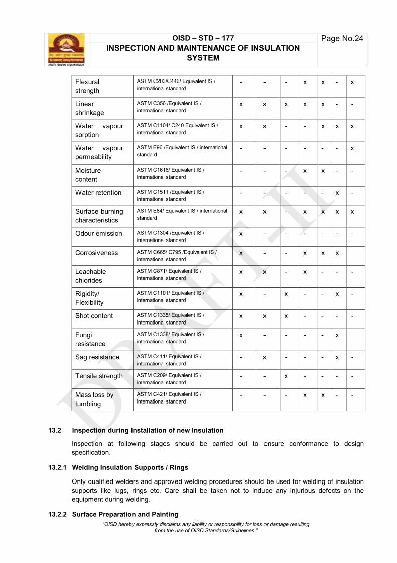
OISD – STD – 177 Page No.24 INSPECTION AND MAINTENANCE OF INSULATION
SYSTEM
“OISD hereby expressly disclaims any liability or responsibility for loss or damage resulting from the use of OISD Standards/Guidelines.”
Flexural strength
ASTM C203/C446/ Equivalent IS / international standard
- - - x x - x
Linear shrinkage
ASTM C356 /Equivalent IS / international standard
x x x x x - -
Water vapour sorption
ASTM C1104/ C240 Equivalent IS / international standard
x x - - x x x
Water vapour permeability
ASTM E96 /Equivalent IS / international standard
- - - - - - x
Moisture content
ASTM C1616/ Equivalent IS / international standard
- - - x x - -
Water retention ASTM C1511 /Equivalent IS / international standard
- - - - - x -
Surface burning characteristics
ASTM E84/ Equivalent IS / international standard
x x - x x x x
Odour emission ASTM C1304 /Equivalent IS / international standard
x - - - - - -
Corrosiveness ASTM C665/ C795 /Equivalent IS / international standard
x - - x x x
Leachable chlorides
ASTM C871/ Equivalent IS / international standard
x x - x - - -
Rigidity/ Flexibility
ASTM C1101/ Equivalent IS / international standard
x - x - - x -
Shot content ASTM C1335/ Equivalent IS / international standard
x x x - - - -
Fungi resistance
ASTM C1338/ Equivalent IS / international standard
x - - - - x
Sag resistance ASTM C411/ Equivalent IS / international standard
- x - - - x -
Tensile strength ASTM C209/ Equivalent IS / international standard
- - x - - - -
Mass loss by tumbling
ASTM C421/ Equivalent IS / international standard
- - - x x - -
13.2 Inspection during Installation of new Insulation
Inspection at following stages should be carried out to ensure conformance to design specification.
13.2.1 Welding Insulation Supports / Rings
Only qualified welders and approved welding procedures should be used for welding of insulation supports like lugs, rings etc. Care shall be taken not to induce any injurious defects on the equipment during welding.
13.2.2 Surface Preparation and Painting

OISD – STD – 177 Page No.25 INSPECTION AND MAINTENANCE OF INSULATION
SYSTEM
“OISD hereby expressly disclaims any liability or responsibility for loss or damage resulting from the use of OISD Standards/Guidelines.”
The surface of equipment/pipelines to be insulated shall be prepared for application of coating of surfaces as described herein.
The painting applied after thorough cleaning shall be checked for its quality and required dry film thickness.
13.2.3 Fixing/Wrapping of Insulation
Holding arrangement or any other fixing arrangements as required should be inspected prior to fixing of the insulation. After wrapping of insulation, it should be checked for proper fitting, uniformity and chances of moisture ingress, if any.
13.2.4 Application of Breather coating (for Hot insulation)
The breather coating mastic is normally applied in two coats with glass cloth reinforcement between the coats. Wet thickness of both the coats corresponding to required DFT and glass cloth overlap should be typical inspection check points.
13.2.5 Application of vapour barrier (for cold insulation)
The vapour barrier mastic is normally supplied in two different colour shades to facilitate inspection during application of both the coats. It is applied with glass cloth reinforcement between the coats. Wet thickness of both the coats corresponding to required Dry Film Thickness (DFT) and glass cloth overlap should be typical inspection check points.
13.2.6 Fixing of Cladding
Inspection of outer cover should be carried out after fixing of the same on the insulated material. Following should be checked:
i. Overlapping between longitudinal and circumferential cover joint.
ii. The pitch at which the screws are fixed.
iii. Spacing of metallic band
13.2.7 Sealing of Joint/Nozzles
All the seal joints as well as the sealing around nozzles and locations where insulation ends should be inspected and ensured that proper sealing is achieved.
13.2.8 Strengthening of insulation & Cladding
Strengthening of insulation & cladding with stainless steels strapping bands as required should be inspected. It may be noted, the band to be used for securement of cladding should be Stainless steel.
13.2.9 Steam Traced Lines
The steam traced line should first be wrapped with Aluminium foil or 24 SWG x ¾” hexagonal mesh stainless steels wire netting so that it passes round the supporting hooks for the tracer line(s). Thus ensuring tracer pipe bearing tightly against the line which is steam traced. This prevents the insulating material from entering the air jacket formed between the insulation and the pipes.
13.2.10 Insulation Finish with UV cured GRP cladding

OISD – STD – 177 Page No.26 INSPECTION AND MAINTENANCE OF INSULATION
SYSTEM
“OISD hereby expressly disclaims any liability or responsibility for loss or damage resulting from the use of OISD Standards/Guidelines.”
Prior to application of GRP cladding, multiplex foil should be applied over the Insulation with an overlapped of 50mm. The overlap joints should be sealed with a sealing tape.
After the application of GRP laminate, the same should be cured by exposing to UV rays / lamp of required UV wavelength as appropriate. A shaded area should be erected over the application area when working outside.
13.3 Periodic Inspection of Existing Insulation
13.3.1 Frequency of Inspection
i. Visual Inspection
Frequency of Visual Inspection shall be once a year for piping and equipment inside units, and once in 2 years for off-site. This visual inspection should be preferably carried out before monsoon, to check for any damage/deterioration, and record the same.
Following should be inspected during visual inspection:
Cladding damaged / missing
Cladding ends open
Corroded cladding
Sweating / icing on cladding (for cold insulation)
Sealing of cladding joints
Steam tracing leakage
Insulation sagging / soaked / missing
Uninsulated section of insulated equipment / piping
Health condition of the jacket / insulation box over the valve body
ii. Thermographic Inspection
Thermographic scanning may be carried out on insulated equipment/pipelines for assessing effectiveness of insulation on need basis. The surface temperatures will indicate the condition of the insulation.
iii. Inspection for CUI
Develop a unit specific Inspection plan to identify the location susceptible to corrosion under insulation and check for corrosion by removing the insulation at the location suspected. It can be carried out on sample basis in such a way that all the identified locations get inspected at least once in 5 years.
13.3.2 Inspection at Corrosion Prone Location
Potential locations for CUI throughout Process Facilities
i. Areas downwind of cooling towers exposed to cooling tower mist
ii. Areas of protrusions (i.e. transition points) through the cladding at manway, nozzles, and other components
iii. Areas of protrusions through insulation for equipment/piping operating at or below ambient, or in cold service

OISD – STD – 177 Page No.27 INSPECTION AND MAINTENANCE OF INSULATION
SYSTEM
“OISD hereby expressly disclaims any liability or responsibility for loss or damage resulting from the use of OISD Standards/Guidelines.”
iv. Areas where insulation cladding is damaged or missing
v. Areas where sealing is missing or hardened on insulation cladding
vi. Areas where the cladding system is bulged or stained
vii. Areas where banding on cladding is missing
viii. Areas where inspection window plugs are missing
ix. Areas where vibration has caused damage to the insulation cladding
x. Areas exposed to steam vents
xi. Areas exposed to process spills, the ingress of moisture, or acid vapours
xii. Areas exposed to deluge systems
xiii. Areas insulated solely for personnel protection
xiv. Areas under the insulation with deteriorated coatings or wraps
xv. Areas with leaking steam tracing
xvi. Pipe and flanges on pressure safety valves
xvii. Systems that operate intermittently
xviii. Systems operating below the atmospheric dew point
xix. Ice-to-air interfaces on insulated systems that continually freeze and thaw
xx. Vertical to horizontal pipe bends
13.3.3 Potential locations for CUI in Piping
i. Dead-legs, vents, and drains
ii. Pipe hangers and supports
iii. Valves and fittings
iv. Bolted on pipe shoes
v. Steam-tracing/electric-tracing tubing penetrations
vi. Termination of insulation at flanges and other piping components
vii. Carbon/low alloy steel flanges, bolting, and other components in high alloy piping
viii. cladding seams on the top of horizontal piping
ix. Termination of insulation on vertical piping
x. Areas where smaller branch connections intersect larger diameter lines
xi. Low points in piping with breaches in the insulation
xii. Close proximity to water (e.g. wharf) and/or ground (e.g. increased absorption)
xiii. Wet due to flooding or submerging into water
xiv. Damage due to foot traffic
xv. Areas on the insulation cladding showing signs of continual surface condensation or mould
xvi. Holes or cuts in the insulation jacket

OISD – STD – 177 Page No.28 INSPECTION AND MAINTENANCE OF INSULATION
SYSTEM
“OISD hereby expressly disclaims any liability or responsibility for loss or damage resulting from the use of OISD Standards/Guidelines.”
13.3.4 General remarks
After inspection and repairs if any, the inspection windows should be refilled with insulation material and the covers fixed back securely in position.
Wherever insulation has been removed to facilitate inspection the same should be re-fixed after inspection and repairs.
13.4 Periodic maintenance of Insulation
Insulation should be checked and maintained at regular intervals. Preventive maintenance of insulation is very much necessary for safe and economic operation.
Insulation must be kept dry to remain effective. The prompt replacement of insulation, which for some reason has been removed or broken off, and the proper maintenance of the moisture barriers to keep insulation dry will result in significant saving in plant production and operational costs.
Areas where damage commonly occurs are listed below:
i. Foot traffic which breaks the weather barrier and damages the insulation.
ii. Cracks caused by expansion
iii. Oil spillage ruins the Vapour barrier / breather coating and soaks into insulation
iv. Gaps on unsealed joints occur in weather barrier jacketing
v. Hot projection through the insulation
vi. Shrinkage of Vapour barrier / breather coating and subsequent cracks
vii. Mechanical damage to insulation due to jobs being carried out in the near vicinity
viii. Damage to insulation due to water jet during fire fighting operation
ix. Check leakage from the steam tracing line
x. Standardise the inspection pockets on vessels, tanks and pipelines. Provide these pockets at the time of fresh insulation.
13.5 Maintenance procedures
13.5.1 Like equipment, insulation also should be checked and maintained at regular intervals.
13.5.2 Due to ice formation at the bare surface during plant operation, application/repair of cold insulation is not possible unless de-icing and drying the exposed surface completely are carried out after taking shut down.
13.5.3 The replacement of damaged/ deteriorated insulation should be done using similar / upgraded type of insulation material.
13.5.4 A major thrust should be given for replacement of detached /deformed cladding. Also circularity should be ensured between new to existing insulation for proper sealing.
13.5.5 In case of prolonged idle period of equipment, removal of insulation may be done to avoid external corrosion underneath the insulation.
13.5.6 Whenever, it may become necessary to remove a large area of insulation to facilitate detailed inspection, in such cases, special care should be taken to remove it. Aluminium sheets should be unscrewed and never torn out. Insulation blankets should be removed carefully and kept on straight flat dry surface. After completion of work, same material can be used for insulation

OISD – STD – 177 Page No.29 INSPECTION AND MAINTENANCE OF INSULATION
SYSTEM
“OISD hereby expressly disclaims any liability or responsibility for loss or damage resulting from the use of OISD Standards/Guidelines.”
purpose. However, at few locations, insulation thickness may have come down due to service over the years. In such cases, insulation thickness could be built up using fresh required extra thickness insulation material.
13.5.7 During turn around/shutdown, wherever the cold insulation is required to be removed (like various strainers and its spool pieces, covers of heat exchangers, pumps, compressor and other equipment, flanges, Non Return Valves (NRV), valves etc.) the same should be reinsulated after completion of the job and before start-up of the plant.
13.5.8 It is not advisable to provide inspection pockets/ windows for cold insulation, as this will tend to increase the chances of ingress of water vapour, moisture, toxic acid fumes etc. and ultimately damage the insulation/ parent material.
14.0 ABBREVATIONS:

OISD – STD – 177 Page No.30 INSPECTION AND MAINTENANCE OF INSULATION
SYSTEM
“OISD hereby expressly disclaims any liability or responsibility for loss or damage resulting from the use of OISD Standards/Guidelines.”
API American Petroleum Institute
ASTM American Society for Testing and Materials
CINI Committee Industrial Insulation
CS Coating System
CUI Corrosion Under Insulation
DFT Dry Film Thickness
EN European Standards
GRP Glass Fibre Reinforced Polyester
IS Indian Standards
MOC Material Of Construction
NACE National Association of Corrosion Engineers
PIR Polyisocyanurate
PS Painting system
PUF Polyurethane Foam
PUR Polyurethane Rigid (Foam)
SP Surface Preparation
SSPC Society For Protective Coatings
TSA Thermal Sprayed Aluminium
UV Ultraviolet
15.0 REFERENCES
API RP 583- Corrosion Under Insulation and Fireproofing
API RP 571- Damage Mechanisms Affecting Fixed Equipment in the Refining Industry
API RP 570- Inspection, Repair, Alteration, and Rerating of In-Service Piping Systems
IS 14164 -Industrial application and finishings of thermal insulation materials at temperatures above -80°c and up to 750°c - code of practice
ISO 15665 - Acoustic insulation for pipes, valves and flanges

OISD – STD – 177 Page No.31 INSPECTION AND MAINTENANCE OF INSULATION
SYSTEM
“OISD hereby expressly disclaims any liability or responsibility for loss or damage resulting from the use of OISD Standards/Guidelines.”
NACE SP 0198 - The Control of Corrosion Under Thermal Insulation and Fireproofing Materials - A Systems Approach
Respective material specification as per IS/EN/ ASTM/ ISO/SSPC-CS/SSPC-SP
16.0 INFORMATIVE ANNEXURES
Annexure-1 Typical hot Insulation diagrams
Annexure-2 Typical cold Insulation diagrams
Annexure-3 List of laboratories internationally recognised for fire test
Annexure-4 Typical material properties/ Industry practices for insulation and ancillary materials
Annexure-5 Typical conventional paint system recommended for units and offsite

OISD – STD – 177 Page No.32 INSPECTION AND MAINTENANCE OF INSULATION
SYSTEM
“OISD hereby expressly disclaims any liability or responsibility for loss or damage resulting from the use of OISD Standards/Guidelines.”
ANNEXURE-1
TYPICAL HOT INSULATION DIAGRAMS

OISD – STD – 177 Page No.33 INSPECTION AND MAINTENANCE OF INSULATION
SYSTEM
“OISD hereby expressly disclaims any liability or responsibility for loss or damage resulting from the use of OISD Standards/Guidelines.”
Figure 1 – Example of Insulation with pipe sections or wire mesh blankets

OISD – STD – 177 Page No.34 INSPECTION AND MAINTENANCE OF INSULATION
SYSTEM
“OISD hereby expressly disclaims any liability or responsibility for loss or damage resulting from the use of OISD Standards/Guidelines.”
Figure 2 - Example of Removable flange box, horizontal

OISD – STD – 177 Page No.35 INSPECTION AND MAINTENANCE OF INSULATION
SYSTEM
“OISD hereby expressly disclaims any liability or responsibility for loss or damage resulting from the use of OISD Standards/Guidelines.”
Figure 3 - Removable flange box, vertical

OISD – STD – 177 Page No.36 INSPECTION AND MAINTENANCE OF INSULATION
SYSTEM
“OISD hereby expressly disclaims any liability or responsibility for loss or damage resulting from the use of OISD Standards/Guidelines.”
Figure 4 - Non- insulated flanges, horizontal and vertical

OISD – STD – 177 Page No.37 INSPECTION AND MAINTENANCE OF INSULATION
SYSTEM
“OISD hereby expressly disclaims any liability or responsibility for loss or damage resulting from the use of OISD Standards/Guidelines.”
Figure 5 - Removable valve box, "T" connection, horizontal

OISD – STD – 177 Page No.38 INSPECTION AND MAINTENANCE OF INSULATION
SYSTEM
“OISD hereby expressly disclaims any liability or responsibility for loss or damage resulting from the use of OISD Standards/Guidelines.”
Figure 6 - Removable valve box, "T" connection, vertical

OISD – STD – 177 Page No.39 INSPECTION AND MAINTENANCE OF INSULATION
SYSTEM
“OISD hereby expressly disclaims any liability or responsibility for loss or damage resulting from the use of OISD Standards/Guidelines.”
Figure 7 - Non contact Insulation

OISD – STD – 177 Page No.40 INSPECTION AND MAINTENANCE OF INSULATION
SYSTEM
“OISD hereby expressly disclaims any liability or responsibility for loss or damage resulting from the use of OISD Standards/Guidelines.”
Figure 8 - Hanger Support

OISD – STD – 177 Page No.41 INSPECTION AND MAINTENANCE OF INSULATION
SYSTEM
“OISD hereby expressly disclaims any liability or responsibility for loss or damage resulting from the use of OISD Standards/Guidelines.”
Figure 9 - Insulation support rings for vertical piping

OISD – STD – 177 Page No.42 INSPECTION AND MAINTENANCE OF INSULATION
SYSTEM
“OISD hereby expressly disclaims any liability or responsibility for loss or damage resulting from the use of OISD Standards/Guidelines.”
Figure 10 - Personal protection

OISD – STD – 177 Page No.43 INSPECTION AND MAINTENANCE OF INSULATION
SYSTEM
“OISD hereby expressly disclaims any liability or responsibility for loss or damage resulting from the use of OISD Standards/Guidelines.”
Steam tracing
Electrical tracing
Figure 11 - Insulation of traced piping

OISD – STD – 177 Page No.44 INSPECTION AND MAINTENANCE OF INSULATION
SYSTEM
“OISD hereby expressly disclaims any liability or responsibility for loss or damage resulting from the use of OISD Standards/Guidelines.”
Figure 12 - Leak detection tube

OISD – STD – 177 Page No.45 INSPECTION AND MAINTENANCE OF INSULATION
SYSTEM
“OISD hereby expressly disclaims any liability or responsibility for loss or damage resulting from the use of OISD Standards/Guidelines.”
.
Figure 13 - Hot Insulation vessel skirt

OISD – STD – 177 Page No.46 INSPECTION AND MAINTENANCE OF INSULATION
SYSTEM
“OISD hereby expressly disclaims any liability or responsibility for loss or damage resulting from the use of OISD Standards/Guidelines.”

OISD – STD – 177 Page No.47 INSPECTION AND MAINTENANCE OF INSULATION
SYSTEM
“OISD hereby expressly disclaims any liability or responsibility for loss or damage resulting from the use of OISD Standards/Guidelines.”
Figure 14 - Insulated Manhole
Figure 15 - Sealing plate for protruding parts

OISD – STD – 177 Page No.48 INSPECTION AND MAINTENANCE OF INSULATION
SYSTEM
“OISD hereby expressly disclaims any liability or responsibility for loss or damage resulting from the use of OISD Standards/Guidelines.”
Figure 16 - Sheeting of vertical vessels

OISD – STD – 177 Page No.49 INSPECTION AND MAINTENANCE OF INSULATION
SYSTEM
“OISD hereby expressly disclaims any liability or responsibility for loss or damage resulting from the use of OISD Standards/Guidelines.”
Figure 17 - Horizontal equipment insulation

OISD – STD – 177 Page No.50 INSPECTION AND MAINTENANCE OF INSULATION
SYSTEM
“OISD hereby expressly disclaims any liability or responsibility for loss or damage resulting from the use of OISD Standards/Guidelines.”
Figure 17 - Horizontal equipment heads

OISD – STD – 177 Page No.51 INSPECTION AND MAINTENANCE OF INSULATION
SYSTEM
“OISD hereby expressly disclaims any liability or responsibility for loss or damage resulting from the use of OISD Standards/Guidelines.”
VESSEL
FLAT BAR
WELDED CLIP
MIN GAP 10mm (3/8 in)
Figure 18 - Vessel insulation support ring - typical detail

OISD – STD – 177 Page No.52 INSPECTION AND MAINTENANCE OF INSULATION
SYSTEM
“OISD hereby expressly disclaims any liability or responsibility for loss or damage resulting from the use of OISD Standards/Guidelines.”
Figure 19 - Details of lifting lugs

OISD – STD – 177 Page No.53 INSPECTION AND MAINTENANCE OF INSULATION
SYSTEM
“OISD hereby expressly disclaims any liability or responsibility for loss or damage resulting from the use of OISD Standards/Guidelines.”
Figure 20 - Removable box for Pump

OISD – STD – 177 Page No.54 INSPECTION AND MAINTENANCE OF INSULATION
SYSTEM
“OISD hereby expressly disclaims any liability or responsibility for loss or damage resulting from the use of OISD Standards/Guidelines.”
Figure 21 - Typical details of vertical Vessel Insulation

OISD – STD – 177 Page No.55 INSPECTION AND MAINTENANCE OF INSULATION
SYSTEM
“OISD hereby expressly disclaims any liability or responsibility for loss or damage resulting from the use of OISD Standards/Guidelines.”
Head lap seam Head and Shell joint
Vertical Nozzle/Manway Band support

OISD – STD – 177 Page No.56 INSPECTION AND MAINTENANCE OF INSULATION
SYSTEM
“OISD hereby expressly disclaims any liability or responsibility for loss or damage resulting from the use of OISD Standards/Guidelines.”
Jacketing Head disc Jacketing at stiffener
Head insulation details for Vessel
Bottom head insulation securement Jacketing lock seam

OISD – STD – 177 Page No.57 INSPECTION AND MAINTENANCE OF INSULATION
SYSTEM
“OISD hereby expressly disclaims any liability or responsibility for loss or damage resulting from the use of OISD Standards/Guidelines.”
ANNEXURE-2
TYPICAL COLD INSULATION DIAGRAMS

OISD – STD – 177 Page No.58 INSPECTION AND MAINTENANCE OF INSULATION
SYSTEM
“OISD hereby expressly disclaims any liability or responsibility for loss or damage resulting from the use of OISD Standards/Guidelines.”
Figure 1 – Example of single piping layer insulation

OISD – STD – 177 Page No.59 INSPECTION AND MAINTENANCE OF INSULATION
SYSTEM
“OISD hereby expressly disclaims any liability or responsibility for loss or damage resulting from the use of OISD Standards/Guidelines.”
Figure 2 –Example of piping insulation, double layer

OISD – STD – 177 Page No.60 INSPECTION AND MAINTENANCE OF INSULATION
SYSTEM
“OISD hereby expressly disclaims any liability or responsibility for loss or damage resulting from the use of OISD Standards/Guidelines.”
Figure 3 –Example of horizontal and vertical elbows

OISD – STD – 177 Page No.61 INSPECTION AND MAINTENANCE OF INSULATION
SYSTEM
“OISD hereby expressly disclaims any liability or responsibility for loss or damage resulting from the use of OISD Standards/Guidelines.”
Figure 4 –Example of valve box horizontal, single layer

OISD – STD – 177 Page No.62 INSPECTION AND MAINTENANCE OF INSULATION
SYSTEM
“OISD hereby expressly disclaims any liability or responsibility for loss or damage resulting from the use of OISD Standards/Guidelines.”
Figure 5 –Example of valve box horizontal, single layer

OISD – STD – 177 Page No.63 INSPECTION AND MAINTENANCE OF INSULATION
SYSTEM
“OISD hereby expressly disclaims any liability or responsibility for loss or damage resulting from the use of OISD Standards/Guidelines.”
Figure 6 –Example of flange box vertical, double layer

OISD – STD – 177 Page No.64 INSPECTION AND MAINTENANCE OF INSULATION
SYSTEM
“OISD hereby expressly disclaims any liability or responsibility for loss or damage resulting from the use of OISD Standards/Guidelines.”
Figure 7 –Example of pipe support

OISD – STD – 177 Page No.65 INSPECTION AND MAINTENANCE OF INSULATION
SYSTEM
“OISD hereby expressly disclaims any liability or responsibility for loss or damage resulting from the use of OISD Standards/Guidelines.”
Figure 8 –Example of pipe trunnion support

OISD – STD – 177 Page No.66 INSPECTION AND MAINTENANCE OF INSULATION
SYSTEM
“OISD hereby expressly disclaims any liability or responsibility for loss or damage resulting from the use of OISD Standards/Guidelines.”

OISD – STD – 177 Page No.67 INSPECTION AND MAINTENANCE OF INSULATION
SYSTEM
“OISD hereby expressly disclaims any liability or responsibility for loss or damage resulting from the use of OISD Standards/Guidelines.”
Figure 9 –Example of pipe hanger
Figure 10 –Example of vapour stop

OISD – STD – 177 Page No.68 INSPECTION AND MAINTENANCE OF INSULATION
SYSTEM
“OISD hereby expressly disclaims any liability or responsibility for loss or damage resulting from the use of OISD Standards/Guidelines.”
Figure 11 –Example of contraction joint

OISD – STD – 177 Page No.69 INSPECTION AND MAINTENANCE OF INSULATION
SYSTEM
“OISD hereby expressly disclaims any liability or responsibility for loss or damage resulting from the use of OISD Standards/Guidelines.”

OISD – STD – 177 Page No.70 INSPECTION AND MAINTENANCE OF INSULATION
SYSTEM
“OISD hereby expressly disclaims any liability or responsibility for loss or damage resulting from the use of OISD Standards/Guidelines.”
Figure 12 –Example of overview vertical vessels
Figure 13 –Example of vessel supports/ brackets

OISD – STD – 177 Page No.71 INSPECTION AND MAINTENANCE OF INSULATION
SYSTEM
“OISD hereby expressly disclaims any liability or responsibility for loss or damage resulting from the use of OISD Standards/Guidelines.”
Figure 14 –Example of lifting lugs

OISD – STD – 177 Page No.72 INSPECTION AND MAINTENANCE OF INSULATION
SYSTEM
“OISD hereby expressly disclaims any liability or responsibility for loss or damage resulting from the use of OISD Standards/Guidelines.”
NOTE
Figure 15 –Example of bottom head insulation

OISD – STD – 177 Page No.73 INSPECTION AND MAINTENANCE OF INSULATION
SYSTEM
“OISD hereby expressly disclaims any liability or responsibility for loss or damage resulting from the use of OISD Standards/Guidelines.”
Figure 16 –Example of overview horizontal vessels

OISD – STD – 177 Page No.74 INSPECTION AND MAINTENANCE OF INSULATION
SYSTEM
“OISD hereby expressly disclaims any liability or responsibility for loss or damage resulting from the use of OISD Standards/Guidelines.”
Figure 17 –Example of heads

OISD – STD – 177 Page No.75 INSPECTION AND MAINTENANCE OF INSULATION
SYSTEM
“OISD hereby expressly disclaims any liability or responsibility for loss or damage resulting from the use of OISD Standards/Guidelines.”
Figure 18 –Example of overview horizontal heat exchanger

OISD – STD – 177 Page No.76 INSPECTION AND MAINTENANCE OF INSULATION
SYSTEM
“OISD hereby expressly disclaims any liability or responsibility for loss or damage resulting from the use of OISD Standards/Guidelines.”
Figure 19 –Example of dome head

OISD – STD – 177 Page No.77 INSPECTION AND MAINTENANCE OF INSULATION
SYSTEM
“OISD hereby expressly disclaims any liability or responsibility for loss or damage resulting from the use of OISD Standards/Guidelines.”
NOTE
Figure 20 –Example of manhole box

OISD – STD – 177 Page No.78 INSPECTION AND MAINTENANCE OF INSULATION
SYSTEM
“OISD hereby expressly disclaims any liability or responsibility for loss or damage resulting from the use of OISD Standards/Guidelines.”
Figure 21 –Example of nozzle connection topside

OISD – STD – 177 Page No.79 INSPECTION AND MAINTENANCE OF INSULATION
SYSTEM
“OISD hereby expressly disclaims any liability or responsibility for loss or damage resulting from the use of OISD Standards/Guidelines.”
Figure 22 –Example of nozzle connection at side/ bottom side
NOTE
Figure 23 –Example of flange connection

OISD – STD – 177 Page No.80 INSPECTION AND MAINTENANCE OF INSULATION
SYSTEM
“OISD hereby expressly disclaims any liability or responsibility for loss or damage resulting from the use of OISD Standards/Guidelines.”
Figure 24 –Example of saddle

OISD – STD – 177 Page No.81 INSPECTION AND MAINTENANCE OF INSULATION
SYSTEM
“OISD hereby expressly disclaims any liability or responsibility for loss or damage resulting from the use of OISD Standards/Guidelines.”
ANNEXURE-3
List of laboratories internationally recognised for fire test

OISD – STD – 177 Page No.82 INSPECTION AND MAINTENANCE OF INSULATION
SYSTEM
“OISD hereby expressly disclaims any liability or responsibility for loss or damage resulting from the use of OISD Standards/Guidelines.”
List of laboratories internationally recognised for fire test
Name of the laboratory/Institute Location
Federal Institute for Material Research and Testing (BAM)
Berlin, Germany
Factory Mutual Research Corporation, (FM) Norwood, MA, USA
Loss Prevention Council (LPC) Borehamwood, Herts, England.
Southwest Research Institute (SWRI) San Antonio, TX, USA
TNO Delft, Netherlands
Underwriters Laboratories Inc.(ULI) Northbrook, IL, USA
Warrington Fire Research Centre Warrington, Cheshire, England.
Health & Safety Executive Buxton
U. S. Department of Transportation ( DOT) USA
Exxova
Canada
Intertek
USA
FRSG
Malaysia

OISD – STD – 177 Page No.83 INSPECTION AND MAINTENANCE OF INSULATION
SYSTEM
“OISD hereby expressly disclaims any liability or responsibility for loss or damage resulting from the use of OISD Standards/Guidelines.”
ANNEXURE-4
Typical material properties/ Industry practices for insulation and ancillary materials

OISD – STD – 177 Page No.84 INSPECTION AND MAINTENANCE OF INSULATION
SYSTEM
“OISD hereby expressly disclaims any liability or responsibility for loss or damage resulting from the use of OISD Standards/Guidelines.”
Typical material properties/ Industry practices for insulation and ancillary materials
1. Non-metallic cladding
Typical property of UV cured Glass Fibre Reinforced Polyester (GRP)
Properties Values Weight (kg/m2) 2 Bending strength (Mpa), min. ISO 178 130 Tensile strength (Mpa), min. ISO 527 50 Elongation at break (%) 1 Flame spread Index (ASTM E84) 20 Water Hanne permeability (g/m2.h.mm Hg), ASTM E96 0.001 Impact resistance (kJ/m2), ISO 179 57 Temper (Barcol) 45
2. Flat spring
Flat springs should be used for large diameter piping and vessels where metal cladding is used. The thickness of spring wire should be min 0.5mm. The maximum expansion of spring should not exceed 60mm beyond its original length. The typical number expansion springs required with respect to equipment diameter and steel temperature has been given below:
Equipment
OD
Equipment Circumference
Number of Jacket Expansion Springs
Steel Temperature (m) (m) 93°C 204°C 315°C 427°C 538°C 649°C
1 2.9 0 0 0 1 1 1 2 5.7 0 1 1 1 2 2 3 9.6 0 1 2 2 2 2
4.6 14.3 1 1 2 3 3 4 6 19.1 1 2 3 3 4 4
7.6 23.9 1 2 3 4 5 6
NOTE: For diameter more than 7.6 m the requirement of number of springs may be extrapolated / decided as per detailed engineering guidelines
3. Mineral fibre at Expansion Joint
Typical material specification should be as under:
Properties Values Density (kg/m3), ASTM D1622 23-24 Compressive strength (kPa), at 10% deformation at 24 deg.C, ASTM C165
0.215
Thermal conductivity (W/mK) at 25°C, max, ASTM C177 0.034 Leachable chlorides content (mg/kg), max, ASTM C871 10

OISD – STD – 177 Page No.85 INSPECTION AND MAINTENANCE OF INSULATION
SYSTEM
“OISD hereby expressly disclaims any liability or responsibility for loss or damage resulting from the use of OISD Standards/Guidelines.”
pH, ASTM C871 6-10.5
4. Multiplex Foil
Multiplex foil should consist of sandwiched sheets of aluminium and polyester. Typical material specification should be as under:
Properties Values
Foil composition:
12 µm polyester film 25 µm Aluminium foil 12 µm polyester film
Tensile strength Yield strength Tear resistance
100 Mpa 70 N / cm
400 g / mm Temperature range +120°C to -60 deg.C Volumetric mass 1.93 kg / dm³ Water vapour permeability in acc. With ASTM E96, procedure E (37.8°C, 90% RH)
max. 10.10-6 g / (m².h.mmHg)
5. Sealing tapes for multiplex foil
Typical material specification for sealing tape for joints in the multiplex foil should be as under
Properties Values
Foil composition
12 µm polyester film
25 µm aluminium foil
12 µm polyester film
adhesive layer: polyacrylate
Total thickness exclusive of adhesive layer 50 µm Temperature range +120°C to -45°C Volumetric mass 1.93 kg / dm³ Water vapour permeability in acc. With ASTM E96, procedure E (37.8 deg. C, 90% R.H.)
Max. 10.10-6 g / (m².h.mmHg)
6. Breather coating:
Typically, breather coating should have the following properties:
fire resistive
have non-volatile content > 60% by weight
flame spread index <10, tested with DFT ~1.6mm over a ¼” inorganic cement board as per ASTM E84 from a reputed laboratory (Annexure-3)
Vapour permeability >1 perm (tested as per ASTM E96 with DFT ~1.6mm)

OISD – STD – 177 Page No.86 INSPECTION AND MAINTENANCE OF INSULATION
SYSTEM
“OISD hereby expressly disclaims any liability or responsibility for loss or damage resulting from the use of OISD Standards/Guidelines.”
7. Primary Vapour Barrier
Typical technical requirement for primary vapour barrier is specified below.
Characteristics Parameter
Consistency Thixotropic soft paste
Water vapour permeance
0.02 metric perms (max) with DFT 1.2-1.3mm as per ASTM E96 procedure-E
Combustibility/ fire resistance
FSI (flame spread index) < 25 as per ASTM E84, tested on a 6.3mm inorganic reinforced cement board with DFT 1.1-1.2 mm
The primary vapour barrier proposed to be applied should have a type test certificate not older than two years for flame spread and vapour permeability. Flame spread test (ASTM E84) should be tested in reputed international laboratory (Annexure-3).
8. Secondary Vapour Barrier Materials should have following typical characteristics:
Characteristics Values Service temperature range (°C) -60 to 120
Volumetric mass (kg/dm3) 1.93
Tensile Strength, MPa 100
Yield Strength, N/cm 70
Tear resistance, g/mm 400
Water Vapour Permeability, ASTM E96 Procedure E (Metric perms)
0.0007
9. Vapour Stop
Minimum technical requirement for primary vapour barrier is specified below.
Characteristics Parameter Water vapour permeance
0.007 metric perms (max) as per ASTM F1249 with DFT 0.5-0.6mm
Tensile strength (of cured dry film) > 8 kg/cm2 as per ASTM D412 measured with 1.2 mm dry film
10. Materials for Contraction Joint
Typical material specification should be as under:
Properties Values Density (kg/m3), ASTM D1622 23-24 Compressive strength (kPa), at 10% deformation at 24°C, ASTM C165 0.215 Thermal conductivity (W/mK) at 25° deg.C, max, ASTM C177 0.034 Leachable chlorides content (mg/kg), max, ASTM C871 10 pH, ASTM C871 6-10.5

OISD – STD – 177 Page No.87 INSPECTION AND MAINTENANCE OF INSULATION
SYSTEM
“OISD hereby expressly disclaims any liability or responsibility for loss or damage resulting from the use of OISD Standards/Guidelines.”
11. PUF Pipe supports
High density PUR/PIR (160-300 kg/m3) conforming to minimum technical specification given below
Characteristics Values Bulk Density( kg/m3) (ASTM D1622) min. 160 200 250 300 Thermal conductivity (ASTM C177) W/mK, max.
at +20 deg.C 0.038 0.040 0.040 0.050 at 0 deg.C 0.034 0.036 0.036 0.046 At minus (-) 40 deg.C 0.033 0.034 0.034 0.044
at minus (-) 80 deg.C 0.030 0.031 0.040 0.040
Compressive Strength, MPa at 23 deg.C in all directions, (ASTM D1621) min. 2.0 2.0 3.0 6.0
Tensile Strength, MPa at 23 deg.C in all directions (ASTM D1623) min. 1.7 2.0 3.0 4.9
Closed Cell content (ASTM D6226 procedure-2
95%
Water Vapour Permeability, g/m2.h ASTM E96 method-A at 23 deg. C and 50% RH, min.
0.8
Water absorption % (by Volume) max. (ASTM D2842)
5%
Linear Coefficient of thermal expansion max.,/°K (ASTM D696) between 23 deg.C and -165 deg. C
70x10-6 m/(mK)
Chlorides, ppm, (ASTM C871, procedure 2) 60 pH values, (ASTM C871) 6-7 Combustibility / fire resistance FSI < 25 ASTM E84
12. Protection guard system (for personnel protection)
Guards and their supports should be of galvanised or Stainless Steel. (The mesh may be painted with yellow stripes, 50 mm wide, and should include a hazard sign indicating „Hot surface‟.). The guard mesh should be of 2mm thick and 12 mm square. Guard should be designed with end cap of 0.7 to 1mm thick from galvanized Al-Zn coated or Al coated carbon steel with recommended spacing of 450mm to 600mm. Care to be taken that end caps are fitted in an orientation that will allow water drainage. If the metal surface requires greater protection, a fibre glass insulation tape can be fitted to area where end caps make contact to protect pipe work and reduce heat transfer. Mesh should be rolled to shape as per normal cladding and should be provided with 50 mm of overlap, sharp edges of cut mesh to be filed. In case of removable guard, the same can be made from toggle clips
The distance of metallic mesh guard to the substrate should be as under: Distance in mm from metallic mesh guard to pipe
surface Pipe diameter Service temperature range (deg.C)
Nominal Bore (inch)
Outer Diameter (mm)
66 to 100 101 to 150 151 to 200 201 to 250
0.25 to 6 13.7 to 168.3 50 50 50 50 8 to 100 219.1 to 2540 100 100 100 100

OISD – STD – 177 Page No.88 INSPECTION AND MAINTENANCE OF INSULATION
SYSTEM
“OISD hereby expressly disclaims any liability or responsibility for loss or damage resulting from the use of OISD Standards/Guidelines.”
Flat surface 20 100 100 100
13. Insulating paint system (for personnel protection)
Typical material specification should be as under:
Properties Values
Solid content, Vol %, (ASTM D2697) 78-85 Shore D Hardness, ASTM D2240 35-55 Thermal conductivity (W/mK) at mean temperature (deg.C) (ASTM C177)
23 50
149
0.095 0.097 0.109
Flame spread index (ASTM E84), max Smoke developed index (ASTM E84) , max
0 5
Adhesion , psi, ASTM D4541 360-700 Emissivity , ASTM E408 0.85
14. Ancillary materials for Hot insulation
Flat spring
Flat springs should be used for large diameter piping and vessels where metal cladding is used. Springs for tensioning bands should be of stainless steel type 304 (SS 304). Typically, the spring may be of 100mm long x 19mm width x 0.5 mm wire diameter.
Securement bands
Bands to be used for securement of Insulation and metal jacketing should be SS 304.
Seals
Seals for tensioning bands should be made from SS 304 and wing type.
Self-tapping screws
Self-tapping screws typically may have 4.8 mm diameter x 13 mm length, SS 304 with slotted pan head or round head. Screws for fastening metal jacketing should have a neoprene washer under its head.
Rivets
Blind pop rivets should be used in preference to screws on tanks for metal jacket securement. Rivet should be made from (SS 304) of 9.5mm long and 5mm diameter.
S and J clips
S and J clips should be made from SS 304. Typically, the width of clips should be 25 mm and thickness 0.5mm. Securement bands should be held in their relative positions with „J‟ clips which should be riveted into permanent position.
Quick release toggle

OISD – STD – 177 Page No.89 INSPECTION AND MAINTENANCE OF INSULATION
SYSTEM
“OISD hereby expressly disclaims any liability or responsibility for loss or damage resulting from the use of OISD Standards/Guidelines.”
The quick release toggle fasteners should be made of SS 304.
Binding wire
Wire should be of generally 1 mm diameter for equipment and 16SWG (1.6mm) for sphere. It should be made of SS 304.
Sacrificial foil
It is used as a barrier material for any chlorides from insulation material and from environment between stainless steel surfaces and insulation material. Aluminium foil should be used for operating temperatures of 400 Deg C and below, and stainless steel foil at operating temperatures in excess of 400 Deg C.
Mineral fibre at Expansion Joint
This is used as an expansion joint in rigid insulation materials. Fibre glass blanket is commonly used.
Joint sealant for metal jacketing
Joint sealant of metal jacketing is used to seal joints. Typical specifications of joint sealant are as follows:
General Characteristics Combustibility/fire resistance Water vapour permeance (max)
Average 52% volume solid as per ASTM C461/Equivalent IS / international standard
FSI (flame spread index) < 20 as per ASTM E84/ Equivalent IS / international standard, tested from a reputed laboratory (Annexure-3).
0.0092 metric perms (as per ASTM F1249 with DFT 2.8mm/Equivalent IS / international standard)
Note: Typically, FSI is tested on a 6.3mm inorganic reinforced cement board with DFT ~2mm.
Multiplex foil
Wherever GRP is used as cladding, multiplex foil should be used underneath.
Sealing tapes for multiplex foil
Sealing tapes are used to seal the joints of multiplex foils.
Heat Transfer Cement
Heat transfer cement is applied onto steam, hot oil or glycol heat tracing pipes prior to insulation and should have following typical characteristics:
15. Ancillary materials for Cold Insulation:
In addition, various ancillary materials are used for fixing of insulation material, sealing of the joints etc.
List of the ancillary materials is as follows

OISD – STD – 177 Page No.90 INSPECTION AND MAINTENANCE OF INSULATION
SYSTEM
“OISD hereby expressly disclaims any liability or responsibility for loss or damage resulting from the use of OISD Standards/Guidelines.”
Adhesive
Adhesives are used for bonding of insulation sections to the substrate and should be essentially compatible with the base insulation material and suitable for the temperature range to which it is exposed.
Joint sealant for insulation blocks
The joint sealant for joints between insulation blocks should be compatible with the base insulation material and suitable for the temperature range to which it is exposed. Material when dry, should have adequate elasticity and not have any crack or flaking.
Typical properties of joint sealant are as under:
General Characteristics Combustibility/ fire resistance Water vapour permeance (max)
Average 82% volume solid as per ASTM D2369
Flame spread and fuel contribution negligible when used as 3.2 mm wide sealant between joints of incombustible insulation blocks
Negligible when measured across 3.2 mm wide sealant between joints of impermeable insulation blocks
Joint sealant for metal cladding
The typical material properties for joint sealant of metal cladding is specified below. Material when dry, should have adequate elasticity and not have any crack or flaking.
General Characteristics Combustibility/ fire resistance Water vapour permeance
(max)
Average 52% volume solid as per ASTM C461
FSI (flame spread index) < 20 as per ASTM E84, tested from a reputed laboratory (Annexure-3)
0.0092 metric perms (as per ASTM F1249 with DFT 2.8mm)
Note: Typically, FSI is tested on a 6.3mm inorganic reinforced cement board with DFT ~2mm
Materials for Contraction Joint
The material to be used in the contraction joints shall be light weight fibre glass blanket. Butyl rubber membrane to be used over contraction joint should be typically 1mm thick.
Glass Cloth / Fabric
The glass cloth to be used for vapour barrier/ vapour stop reinforcement should be prepared from E-glass.
Adhesive Synthetic Tape
The Glass fibre-reinforced synthetic tape used to secure the inner layers of polyisocyanurate/Cellular glass should be pressure sensitive glass fibre reinforced tape.

OISD – STD – 177 Page No.91 INSPECTION AND MAINTENANCE OF INSULATION
SYSTEM
“OISD hereby expressly disclaims any liability or responsibility for loss or damage resulting from the use of OISD Standards/Guidelines.”
Bands
Band to secure last layer of insulation materials and weatherproof jacketing should be SS 304 / SS 316.
Pipe supports
Unless otherwise specified pipe supports for cold services should be high density PUF (160-300 kg/m3).
ANNEXURE-5
A typical conventional paint system recommended for units and offsite for insulated piping, equipment, storage vessels, tanks, columns etc.

OISD – STD – 177 Page No.92 INSPECTION AND MAINTENANCE OF INSULATION
SYSTEM
“OISD hereby expressly disclaims any liability or responsibility for loss or damage resulting from the use of OISD Standards/Guidelines.”
A typical conventional paint system recommended for units and offsite for insulated piping, equipment, storage vessels, tanks, columns etc. of Carbon Steel, Low Temperature Carbon Steel, alloy steel & stainless steels in all environments is given as under:
Design temp(Deg.C
)
Surface preparation & pre
erection/ shop primer
Coating system Total DFT
Microns
( min.)
Remarks
Primer Finish paint
Carbon steel, LTCS and alloy steel piping, storage tanks, vessels, Equipment etc.
minus(-) 45 to 125
SSPC-SP-10; 1coat of CS-1 @ 75µ DFT/coat
None
2 coats of
CS-1 @75µ DFT/coat
225 The system can be used for cyclic operation in the temperature range
176 to 450
(CS)
SSPC-SP-10; 1coat of CS-2 @ 20µ DFT/coat
None 2 coats of
CS-2 @20µ DFT/coat
60
minus(-) 45 to 200
SSPC-SP-10; 1coat of CS-6 @ 150µ DFT/coat
1coat of CS-6 @ 150µ DFT/coat
300 The system can be used for cyclic operation in the temperature range
minus(-) 180 to 650
SSPC-SP-10; 1coat of CS-3 @ 125µ DFT/coat
None 1coat of CS-3 @ 125µ DFT/coat
250 The system can be used for cyclic operation in the temperature range
minus(-) 45 to 550
SSPC-SP-5, CS-4 @ 300-375 DFT
None Optional:
Sealer coating with thinned epoxy based or silicon coating @ 45µ DFT
300-375 (+45 if finish Paint is considered)
The system can be used for cyclic operation in the temperature range
Stainless Steel, Alloy Steel, Alloy-20 Piping, Vessels & Equipment

OISD – STD – 177 Page No.93 INSPECTION AND MAINTENANCE OF INSULATION
SYSTEM
“OISD hereby expressly disclaims any liability or responsibility for loss or damage resulting from the use of OISD Standards/Guidelines.”
minus(-) 45 to 125
SSPC-SP-7; 1coat of CS-1 @ 75µ DFT/coat
None
2 coats of
CS-1 @75µ DFT/coat
225 The system can be used for cyclic operation in the temperature range
minus(-) 45 to 200
SSPC-SP-7; 1coat of CS-6 @ 150µ DFT/coat
1coat of CS-6 @ 150µ DFT/coat
300 The system can be used for cyclic operation in the temperature range
126 to 550 SSPC-SP-7; 1coat of CS-5 @ 125µ DFT/coat
None 1coat of CS-5 @ 125µ DFT/coat
250
minus(-) 180 to 650
SSPC-SP-7; 1coat of CS-3 @ 125µ DFT/coat
None 1coat of CS-3 @ 125µ DFT/coat
250 The system can be used for cyclic operation in the temperature range
minus(-) 45 to 550
SSPC-SP-5, CS-4 @ 300-375 µ DFT
None Optional:
Sealer coating with thinned epoxy based or silicon coating @ 45µ DFT
300-375 (+45 if finish Paint is considered)
The system can be used for cyclic operation in the temperature range
Coating system description:
CS-1: Two- component Epoxy phenolic coating cured with Polyamine adduct hardener
CS-2: Heat resistant silicone Aluminium Paint suitable up to 540°C dry temp.
CS-3: Inert polymeric matrix
CS-4: Thermal-sprayed aluminium (TSA) with minimum of 99% aluminium
CS-5: Ambient temperature curing Poly Siloxane
CS-6: Novolac epoxy phenolic coating cured with Polyamine adduct hardener
Notes: a) Inorganic zinc-rich coating should not be used by itself under thermal insulation in the 50 to 175 °C service
temperature ranges for long-term or cyclic service. Zinc provides inadequate corrosion resistance in closed, sometimes wet, environments. At elevated temperatures greater than approximately 60 °C, the zinc may undergo a galvanic reversal whereby the zinc becomes Cathodic to the carbon steel
b) To avoid surface contamination, austenitic and duplex stainless steels should be blasted with grit such as silicon carbide, garnet, etc.