oil coolers for temperature optimization in … coolers for temperature optimization in hydraulic...
TRANSCRIPT
Oil Coolers For Temperature Optimization In Hydraulic SystemsCatalog HY10-1700/Americas

WARNINGFAILURE OR IMPROPER SELECTION OR IMPROPER USE OF THE PRODUCTS AND/OR SYSTEMS DESCRIBED HEREIN OR RELATED ITEMS CAN CAUSE DEATH, PERSONAL INJURY AND PROPERTY DAMAGE.
This document and other information from Parker Hannifin Corporation, its subsidiaries and authorized distributors provide product and/or system options for further investigation by users having expertise. It is important that you analyze all aspects of your application, including consequences of any failure and review the information concerning the product or system in the current product catalog. Due to the variety of operating conditions and applications for these products or systems, the user, through its own analysis and testing, is solely responsible for making the final selection of the products and systems and assuring that all performance, safety and warning requirements of the application are met.
The products described herein, including without limitation, product features, specifications, designs, availability and pricing, are subject to change by Parker Hannifin Corporation and its related companies at any time without notice.
© Copyright 2013, Parker Hannifin Corporation. All rights reserved.
!
Offer of SaleThe items described in this document are hereby offered for sale
by Parker Hannifin Corporation, its subsidiaries or its authorized
distributors. This offer and its acceptance are governed by the
provisions in the “Offer of Sale.”
NOTE: Failure or improper selection or
improper use of coolers or related items
can cause death, personal injury and
property damage. Parker Hannifin shall
not be liable for any incidental,
consequential or special damages that
result from use of the information
contained in this publication.
If you have questions about
the products contained in this
catalog, or their applications,
please contact:
Extra care is taken in the
preparation of this literature, but
Parker is not responsible for any
inadvertent typographical errors
or omissions. Information in this
catalog is only accurate as of
the date of publication. For a
more current information base,
please consult the Parker
Accumulator Division web site at
parker.com/accumulator.
Accumulator & Cooler
Division - Americas
phone 815 636 4100
fax 815 636 4111
parker.com/accumulator

Table of ContentsOil Coolers ....................................................................................... 4
More Cooling Per $ .......................................................................... 6
ULAC With AC Motor ...................................................................... 9
Cooling Performance .............................................................. 10
Pressure Drop ......................................................................... 11
Dimensions ............................................................................. 12
Order Key and Technical Specifications ................................... 14
ULOC Cooling System .................................................................. 15
Cooling Performance .............................................................. 16
Dimensions ............................................................................. 17
Order Key and Technical Specifications ................................... 18
ULDC With DC Motor .................................................................... 19
Cooling Performance .............................................................. 20
Pressure Drop ......................................................................... 20
Dimensions ............................................................................. 21
Order Key and Technical Specifications ................................... 22
ULHC With Hydraulic Motor ......................................................... 23
Cooling Performance .............................................................. 24
Pressure Drop ......................................................................... 25
Dimensions ............................................................................. 26
Order Key and Technical Specifications ................................... 28
OAW Cooling System .................................................................... 29
General ................................................................................... 30
Cooling Performance, Pressure Drop, Dimensions .................. 31
Installation ............................................................................... 34
Accessories ................................................................................... 37
Cooling Modules/Combination Cooler ........................................ 38
Product Groups ............................................................................. 39

4
Choosing the right cooler requires precise system sizing. The most reliable way to size a cooler is with the aid of our calculation program. This program, together with precise evaluations from our experienced, skilled engineers, gives you the opportunity for more cooling per $ invested. Overheating – an expensive
problemAn underestimated cooling capacity produces a temperature that is too high. The consequences are poor lubricating properties, higher internal leakage, a higher risk of cavitation, damaged components, etc. Overheating leads to a significant drop in efficiency which can be detrimental to our environment.
Temperature optimization – a basic prerequisite for cost-efficient operation Temperature balance in a hydraulic system occurs when the cooler can cool down the energy input that the system does not consume – the system’s lost energy (Ploss = Pcool = Pin – Pused).
Temperature optimization occurs at the temperature at which the oil viscosity is maintained at
recommended values. The correct working temperature produces a number of economic and environmental benefits:
• The hydraulic system’s
useful life is extended.
• The oil’s useful life is
extended.
• The hydraulic system’s
availability increases –
more operating time and
fewer shutdowns.
• Service and repair costs
are reduced.
• High efficiency level
maintained in continuous
operation – the system’s
efficiency falls if the
temperature exceeds the
ideal working temperature.
Oil Coolers
Parker is a global player specializing in innovative, efficient system solutions for temperature optimization and
energy storage. All over the world, our products are working in the most diverse environments and applications.
Lifetime
Cooling capacity

5
ULAC with AC MotorFor industrial use – maximum cooling capacity 400 HP*
Optimized design with the right choice of materials and components ensures reliable and long lasting cooling with low service and maintenance costs.
Compact design results in a lighter weight unit with higher cooling capacity and lower pressure drop.
Easy to maintain and easy to retrofit into many applications.
Quiet fan design due to optimization of material and blade.
AC motor – NEMA three phase motors are standard. A wide range of operating voltages and frequencies available.
Cooler core with low pressure drop and high cooling capacity.
ULOC Cooling SystemFor industrial use – maximum cooling capacity 60 HP
Optimized design and the right choice of materials and components produce a long useful life, high availability and low service and maintenance costs.
Integrated circulation pump produces an even flow with low pressure pulsations.
Easy to maintain and easy to retrofit in many applications.
Compact design and low weight.
Quiet fan and pump.
Cooler core with low pressure drop and high cooling capacity.
ULDC with DC MotorFor mobile use – maximum cooling capacity 40 HP
Optimized design with the right choice of materials and components ensures reliable and long lasting cooling with low service and maintenance costs.
Compact design results in a lighter weight unit with higher cooling capacity and lower pressure drop.
Easy to maintain and easy to retrofit into many applications.
DC motor 12V/24V
Quiet fan and fan motor.
OAW Cooling SystemFor mobile and industrial use – maximum cooling capacity 274 HP
Optimized design and the right choice of materials and components ensures reliable and long lasting cooling with low service and maintenance costs.
Compact design for easy installation.
Turbulent water flow prevents clogging and reduces maintenance.
Low water consumption for economical operation.
SAE O-ring connections for ease of assembly and leak-proof operation.
Maximum material efficiency with no “Dead Zone” outside gaskets.
ULHC with Hydraulic MotorFor mobile and industrial use – maximum cooling capacity 215 HP
Optimized design and the right choice of materials and components produce a long useful life, high availability and low service and maintenance costs.
Compact design results in a lighter weight unit with higher cooling capacity and lower pressure drop.
Easy to maintain and easy to retrofit into many applications.
Hydraulic motor with displacement from 8.4 cc/rev to 25.2 cc/rev.
Collar bearing for fan motor on larger models provides longer operating life.
Quiet fan design due to optimization of material and blade.
Cooler core with low pressure drop and high cooling capacity.
*At 250 gpm and 70 °F ITD

6
Optimal sizing produces efficient cooling. Correct sizing requires knowledge and experience. Our calculation program, combined with our engineers’ support, gives you access to this very knowledge and experience. The result is more cooling per $ invested.
In-depth system review as an added value.A more wide-ranging review of the hydraulic system is often a natural element of cooling calculations. Other potential system improvements can then be discussed – e.g. filtering, offline or online cooling, etc. Contact usfor further guidance and information.
Parker’s quality and performance guarantee assures you of maximum system performance and reliability. A continual desire for more cost efficient and environmentally friendly hydraulic systems requires continuous development. Areas where we are continuously seeking to improve performance include cooling capacity, noise level, pressure drop and fatigue.
Meticulous quality and performance tests are conducted in our laboratory. All tests and
measurements take place in accordance with standardized methods – cooling capacity in accordance with EN1048, noise level ISO 3743, pressure drop EN 1048 and fatigue ISO 10771-1.For more information about our standardized tests, ask for “Parker’s blue book – a manual for more reliable cooler purchasing.”
More Cooling Per $with precise calculations and our engineers’ support

7
Calculate the cooling capacity requirement
Enter your values ...
... get suggested solution
Cooling
capacity
requirement?
Installed
horse power
Flow?
Pressure?
Pump efficiency?
Measure in
your existing
unit
Contact
Parker USA
representative
Theoretical
horse power
losses
Choose the right kind of cooler

8
Notes

9
ULAC with AC Motor For industrial use – cooling capacity up to 400 HP
Catalog HY10-1700/Americas ULAC
The ULAC oil cooler with AC motor is optimized
for use in the industrial sector. Together with a wide
range of accessories, the ULAC cooler is suitable for
installation in most applications and environments.
• Optimized design with right choice
of materials and components ensures
a reliable and long lasting cooler with
low service and maintenance costs.
• Compact design resulting in lighter
weight unit yet with higher cooling
capacity and lower pressure drop.
• Easy to maintain and easy to retrofit
into many applications.
• Quiet fan design due to optimization
of material and blade design.
• AC motor – NEMA three phase motors
are standard. Wide range of operating
voltages and frequencies available.
• Cooler core with low pressure drop
and high cooling capacity.

10
Catalog HY10-1700/Americas ULAC
The cooling capacity curves are based on an ETD (Entering Temperature Difference) of 1 °F. For example,
oil temperature of 140 °F and air temperature of 70 °F yields a temperature difference of 70 °F. Multiply
the number from the cooling graphs corresponding to the specific flow rate by the ETD for the particular
application to get the total heat duty.
ULAC Cooling Performance
1,800
1,600
1,400
1,200
1,000
800
600
400
200
0 10 200 30 40 50 60
Hea
t D
uty
(B
tu/h
r/°F
)
Oil Flow Rate (gpm)
COOLING PERFORMANCE ULAC 007 - ULAC 023
8,500
7,500
6,500
5,500
4,500
3.500
2.500
1,500
500
0 20 40 60 80 100 120
Hea
t D
uty
(B
tu/h
r/°F
)
Oil Flow Rate (gpm)
ULAC-078G
ULAC-112H
Cooling capacity tolerance ± 10%.
ULAC-016B
ULAC-007B
ULAC-011B
ULAC-023D
COOLING PERFORMANCE ULAC 033 - ULAC 112
ULAC-058G
ULAC-044F
ULAC-033F
ULAC-044D
ULAC-033D
11
Catalog HY10-1700/Americas ULAC
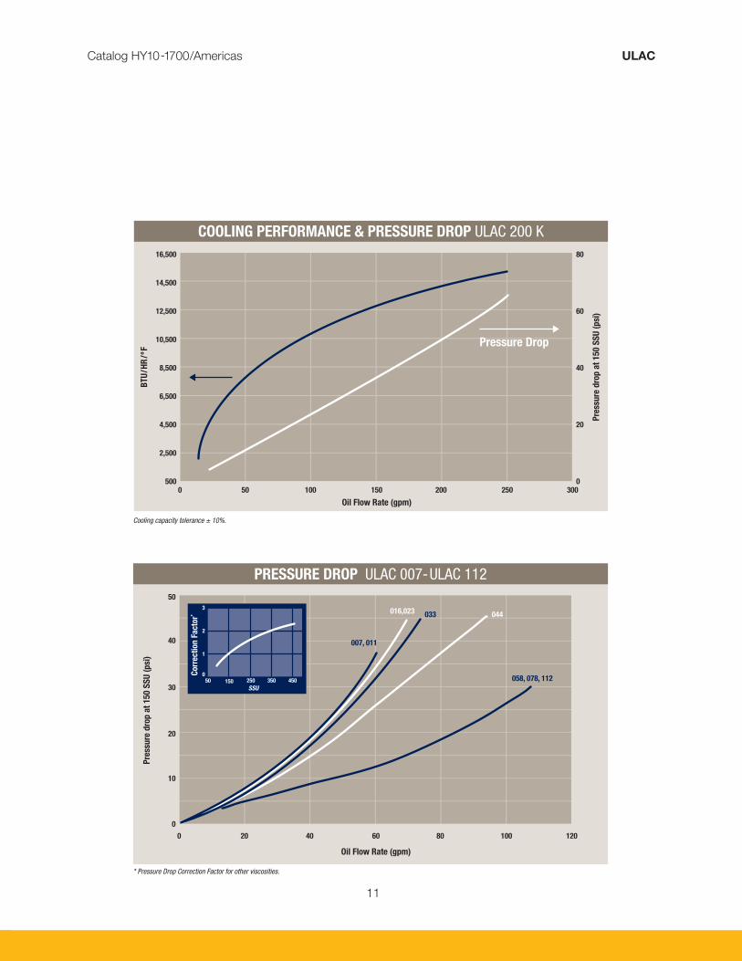
COOLING PERFORMANCE & PRESSURE DROP ULAC 200 K16,500
14,500
12,500
10,500
8,500
6,500
4,500
2,500
5000 50 100 150 200 250 300
BT
U/H
R/º
F
Pre
ssu
re d
rop
at
15
0 S
SU
(p
si)
Oil Flow Rate (gpm)
Pressure Drop
80
60
40
20
0
Cooling capacity tolerance ± 10%.
50
40
30
20
10
0
0 20 40 60 80 100 120
Pre
ssu
re d
rop
at
15
0 S
SU
(p
si)
Oil Flow Rate (gpm)
007, 011
016,023033 044
058, 078, 112
Corr
ecti
on
Fa
cto
r*
3
2
1
050 150 250 350 450
SSU
* Pressure Drop Correction Factor for other viscosities.
PRESSURE DROP ULAC 007-ULAC 112

12
Catalog HY10-1700/Americas ULAC
TYPEAcoustic Pressure
Level
LpA dB(A) 3 Ft.*
No. Of Poles/
Capacity
HP
Weight
Lbs. (Approx.)P
SAE O-RingQ
SAE O-Ring Boss
ULAC 007B 69 4/0.5 33 ½" (#8) 1" (#16)ULAC 011B 71 4/0.5 44 ½" (#8) 1" (#16)ULAC 016B 74 4/0.5 53 ½" (#8) 1" (#16)ULAC 023D 81 4/1 79 ½" (#8) 1" (#16)ULAC 033D 82 4/1 115 ½" (#8) 1¼" (#20)ULAC 033F 86 4/3 170 ½" (#8) 1¼" (#20)ULAC 044D 83 4/1 143 ½" (#8) 1¼" (#20)ULAC 044F 87 4/3 197 ½" (#8) 1¼" (#20)ULAC 058G 90 4/5 264 ¾" (#12) 1½" (#24)ULAC 078G 92 4/5 434 ¾" (#12) 1½" (#24)ULAC 112H 96 4/7.5 542 ¾" (#12) 1½" (#24)ULAC 200K 93 6/15 1,030 NA CODE 61 SAE 2" FLANGE
* Noise level tolerance ± 3 dB(A).

13
Catalog HY10-1700/Americas ULAC
TYPE A B C D E F G H I J K L M Nø
ULAC 007B 5.2 6.3 3.2 8.0 0.24 11.7 15.6 8.0 14.4 20.1 8.4 19.8 8.8 0.35ULAC 011B 5.4 9.0 3.2 8.0 0.12 14.3 18.5 8.0 17.3 20.1 9.8 20.8 9.8 0.35ULAC 016B 5.2 11.7 3.2 8.0 0.28 17.0 20.7 8.0 19.5 20.1 10.9 21.6 10.7 0.35ULAC 023D 5.2 14.9 3.2 14.0 0.20 20.2 24.0 14.0 22.8 20.1 12.6 22.2 11.3 0.35ULAC 033D 5.2 19.1 3.2 14.0 NA 24.5 28.4 14.0 27.2 20.1 14.8 23.1 12.5 0.35ULAC 033F 5.2 19.1 3.2 14.0 NA 24.5 28.4 14.0 27.2 24.0 14.8 25.6 12.5 0.55ULAC 044D 4.6 26.1 3.2 14.0 NA 31.5 34.1 14.0 27.2 20.1 17.6 24.1 13.3 0.35ULAC 044F 4.6 26.1 3.2 14.0 NA 31.5 34.1 14.0 27.2 24.0 18.3 26.6 13.5 0.55ULAC 058G 5.2 26.1 3.2 20.0 NA 31.5 35.4 20.0 34.2 24.0 18.3 29.9 15.2 0.55ULAC 078G 5.2 32.3 3.9 26.8 NA 38.9 41.4 20.4 40.2 35.4 21.1 30.9 16.2 0.55ULAC 112H 5.1 38.8 3.9 31.1 0.14 45.4 47.8 23.6 46.7 35.4 24.4 31.9 17.2 0.55ULAC 200K 7.2 50.9 5.0 49.6 1.2 61.0 64.2 55.9 59.4 35.4 32.7 41.5 18.7 0.71
All dimensions listed above are in inches.

14
Catalog HY10-1700/Americas ULAC
Technical Specifications
FLUID COMBINATIONS
Mineral oil Oil/water emulsion Water glycol Phosphate ester
MATERIAL
Cooler core AluminumFan blades/hub Glass fiber reinforced polypropylene/
AluminumFan housing SteelFan guard SteelOther parts SteelSurface treatment Electrostatically powder-coated
COOLER CORE
Maximum static working pressure 300 psiDynamic working pressure 200 psi*Heat transfer tolerance ± 6 %Maximum oil inlet temperature 250 °F
*Tested in accordance with ISO/DIS 10771-1
COOLING CAPACITY CURVES
Cooling capacity curves are based on testing in accordance with EN1048 with ISO VG 46.
CONTACT PARKER FOR ADVICE ON
Oil temperatures > 250 °FOil viscosity > 100 cSt / 500 SSUAggressive environmentsEnvironments with heavy airborne particulatesHigh-altitude locations
Order Key for ULAC Oil CoolersAll positions must be filled in when ordering.
EXAMPLE:
ULAC - 007B - M - 100 - SA Series Model Motor Type Thermoswitch Core Bypass 1 2 3 4 5
1. OIL COOLER SERIES WITH AC MOTOR; ULAC
2. COOLER SIZE/MODEL
007B, 011B, 016B, 023D, 033F, 033D, 044F, 044D,058G, 078G, 112H and 200K.
3. MOTOR TYPE
No motor = WThree-phase 190/380V 50 Hz, 208-230/460V 60 Hz = M*
Three-phase 208-230/460V 60 Hz = NThree-phase 230/460V 60 Hz = PThree-phase 575V 60 Hz = QSingle-phase 115/230V 60 Hz = RSingle-phase 230 V 60 Hz = SExplosion proof, Division 1, Class 1 Group D, Class II Group F & G, T3C = XNot listed, consult Accumulator and Cooler Division = Z
*The M-motor is our standard motor sizes 1 HP and lower. The performance at 50 HZ will be reduced by approximately 10%
4. THERMOSWITCH
No thermoswitch = 000100 °F = 100120 °F = 120140 °F = 140160 °F = 160 175 °F = 175195 °F = 195Not listed, consult Accumulator and Cooler Division = ZZZ
5. CORE BYPASS*
No Bypass = SW20 psi External Hose Bypass (standard option) = SA65 psi External Hose Bypass (standard option) = SB30 psi External Tube Bypass = SG75 psi External Tube Bypass = SH120 psi External Tube Bypass = SJ120 °F External Thermo-Bypass = SM140 °F External Thermo-Bypass = SN160 °F External Thermo-Bypass = SP 195 °F External Thermo-Bypass = SQFull Flow External Bypass = SF
* The standard cores are single pass. Two pass cores and other options available upon request, please consult Accumulator and Cooler Division.
The information in this brochure is subject to change without prior notice.
15
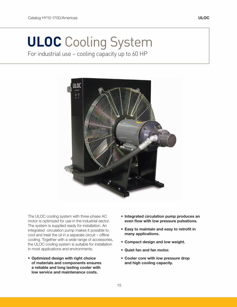
ULOC Cooling System For industrial use – cooling capacity up to 60 HP
The ULOC cooling system with three-phase AC
motor is optimized for use in the industrial sector.
The system is supplied ready for installation. An
integrated circulation pump makes it possible to
cool and treat the oil in a separate circuit – offline
cooling. Together with a wide range of accessories,
the ULOC cooling system is suitable for installation
in most applications and environments.
• Optimized design with right choice
of materials and components ensures
a reliable and long lasting cooler with
low service and maintenance costs.
• Integrated circulation pump produces an
even flow with low pressure pulsations.
• Easy to maintain and easy to retrofit in
many applications.
• Compact design and low weight.
• Quiet fan and fan motor.
• Cooler core with low pressure drop
and high cooling capacity.
Catalog HY10-1700/Americas ULOC

16
TYPENom. Oil
Flow Rate
(gpm)
Cooling
Capacity
at 50 °F ETD (Btu/hr)
Cooling
Capacity
Btu/hr/°F
Acoustic Pressure
Level
LpA dB(A) 3 Ft.*
Motor Capacity /
No. Of Poles
HP
Motor
ULOC 007D - A 6.3 15,500 310 71 1/4 1-4-143TCULOC 007D - B 12.7 19,000 380 71 1/4 1-4-143TCULOC 007E - C 19.0 21,000 420 72 2/4 2-4-145TCULOC 007E - D 25.4 22,500 450 72 2/4 2-4-145TCULOC 011D - A 6.3 24,000 480 74 1/4 1-4-143TCULOC 011D - B 12.7 28,500 570 74 1/4 1-4-143TCULOC 011E - C 19.0 32,000 640 74 2/4 2-4-145TCULOC 011E - D 25.4 34,500 690 74 2/4 2-4-145TCULOC 016E - A 6.3 33,500 670 78 2/4 2-4-145TCULOC 016E - B 12.7 41,000 820 78 2/4 2-4-145TCULOC 016E - C 19.0 47,000 940 78 2/4 2-4-145TCULOC 016E - D 25.4 50,000 1,000 78 2/4 2-4-145TCULOC 023F - B 12.7 60,000 1,200 82 3/4 3-4-182TCULOC 023F - C 19.0 65,000 1,300 82 3/4 3-4-182TCULOC 023F - D 25.4 70,000 1,400 82 3/4 3-4-182TCULOC 033G - C 19.0 80,000 1,600 87 5/4 5-4-182TCULOC 033G - D 25.4 90,000 1,800 87 5/4 5-4-184TCULOC 044G - C 19.0 95,000 1,900 88 5/4 5-4-182TCULOC 044G - D 25.4 105,000 2,100 88 5/4 5-4-182TCElectric motors specified are calculated for max. Working pressure 90 psi at 125 cSt and 50 Hz, 60 psi at 125 cSt and 60 Hz.If you require higher pressure, please contact us for a choice of motors with a higher output. * Noise level tolerance ± 3 dB(A).
Catalog HY10-1700/Americas ULOC
17
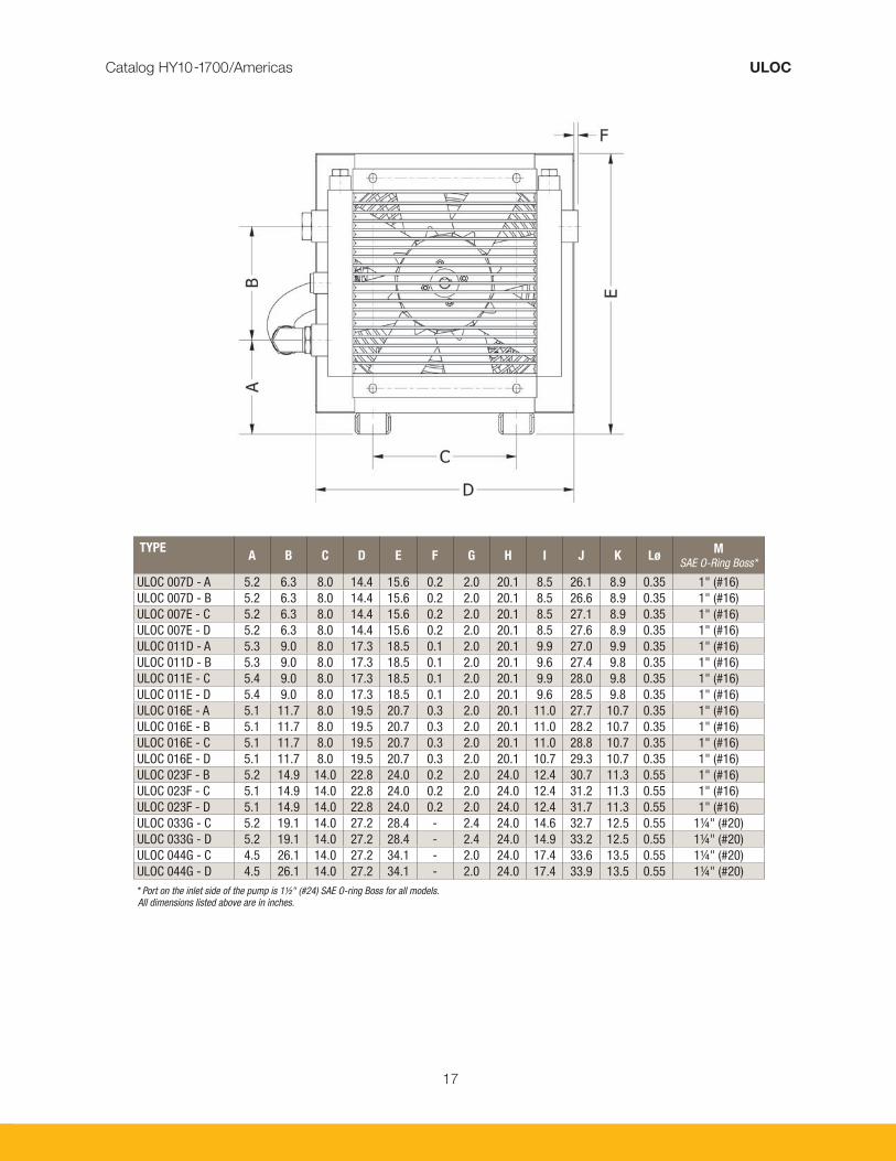
TYPEA B C D E F G H I J K Lø
MSAE O-Ring Boss*
ULOC 007D - A 5.2 6.3 8.0 14.4 15.6 0.2 2.0 20.1 8.5 26.1 8.9 0.35 1" (#16)ULOC 007D - B 5.2 6.3 8.0 14.4 15.6 0.2 2.0 20.1 8.5 26.6 8.9 0.35 1" (#16)ULOC 007E - C 5.2 6.3 8.0 14.4 15.6 0.2 2.0 20.1 8.5 27.1 8.9 0.35 1" (#16)ULOC 007E - D 5.2 6.3 8.0 14.4 15.6 0.2 2.0 20.1 8.5 27.6 8.9 0.35 1" (#16)ULOC 011D - A 5.3 9.0 8.0 17.3 18.5 0.1 2.0 20.1 9.9 27.0 9.9 0.35 1" (#16)ULOC 011D - B 5.3 9.0 8.0 17.3 18.5 0.1 2.0 20.1 9.6 27.4 9.8 0.35 1" (#16)ULOC 011E - C 5.4 9.0 8.0 17.3 18.5 0.1 2.0 20.1 9.9 28.0 9.8 0.35 1" (#16)ULOC 011E - D 5.4 9.0 8.0 17.3 18.5 0.1 2.0 20.1 9.6 28.5 9.8 0.35 1" (#16)ULOC 016E - A 5.1 11.7 8.0 19.5 20.7 0.3 2.0 20.1 11.0 27.7 10.7 0.35 1" (#16)ULOC 016E - B 5.1 11.7 8.0 19.5 20.7 0.3 2.0 20.1 11.0 28.2 10.7 0.35 1" (#16)ULOC 016E - C 5.1 11.7 8.0 19.5 20.7 0.3 2.0 20.1 11.0 28.8 10.7 0.35 1" (#16)ULOC 016E - D 5.1 11.7 8.0 19.5 20.7 0.3 2.0 20.1 10.7 29.3 10.7 0.35 1" (#16)ULOC 023F - B 5.2 14.9 14.0 22.8 24.0 0.2 2.0 24.0 12.4 30.7 11.3 0.55 1" (#16)ULOC 023F - C 5.1 14.9 14.0 22.8 24.0 0.2 2.0 24.0 12.4 31.2 11.3 0.55 1" (#16)ULOC 023F - D 5.1 14.9 14.0 22.8 24.0 0.2 2.0 24.0 12.4 31.7 11.3 0.55 1" (#16)ULOC 033G - C 5.2 19.1 14.0 27.2 28.4 - 2.4 24.0 14.6 32.7 12.5 0.55 1¼" (#20)ULOC 033G - D 5.2 19.1 14.0 27.2 28.4 - 2.4 24.0 14.9 33.2 12.5 0.55 1¼" (#20)ULOC 044G - C 4.5 26.1 14.0 27.2 34.1 - 2.0 24.0 17.4 33.6 13.5 0.55 1¼" (#20)ULOC 044G - D 4.5 26.1 14.0 27.2 34.1 - 2.0 24.0 17.4 33.9 13.5 0.55 1¼" (#20) * Port on the inlet side of the pump is 1½" (#24) SAE O-ring Boss for all models. All dimensions listed above are in inches.
Catalog HY10-1700/Americas ULOC

18
The information in this brochure is subject to change without prior notice.
Technical Specifications
COOLER CORE
Maximum static working pressure 300 psiDynamic working pressure 200 psi*Heat transfer tolerance ± 6 %Maximum oil inlet temperature 250 °F
* Tested in accordance with ISO/DIS 10771-1
• ULOC is designed primarily for synthetic oils, vegetable oils and mineral oil type HL/HLP in accordance with DIN 51524. Maximum oil temperature 210 °F.
• Maximum negative pressure in the inlet line is 6 psi with an oil-filled pump. Maximum pressure on the pump’s suction side is 8 psi.
• Maximum working pressure for the pump is 150 psi.
Heat transfer tolerance ± 6 %
MATERIAL
Cooler core AluminumFan blades/hub Glass fiber reinforced polypropylene/
AluminumFan housing SteelFan guard SteelPump housing AluminumOther parts SteelSurface treatment Electrostatically powder-coated
CONTACT PARKER FOR ADVICE ON
Oil temperatures > 250 °FOil viscosity > 100 cSt / 500 SSUAggressive environmentsEnvironments with heavy airborne particulatesHigh-altitude locations
Order Key for ULOC Cooling SystemsAll positions must be filled in when ordering.
EXAMPLE:
ULOC - 007D - M - A - SA Series Model Motor Type Pump Flow Rate Core Bypass
1 2 3 4 5
1. OIL COOLER SERIES OFFLINE, WITH PUMP; ULOC
2. COOLER SIZE/MODEL
007D, 007E, 011D, 011E, 016E, 023F, 033G, 044G
3. MOTOR TYPE
No motor = WThree phase, 190/380V 50 Hz, 208-230/460V 60Hz = MThree phase, 575V 60Hz = QNot listed, consult Accumulator and Cooler Division = Z
Performance at 50 Hz will be reduced by approximately 10%
4. PUMP FLOW RATE (GPM)
6 = A12 = B19 = C25 = D
5. CORE BYPASS*
No Bypass = SW20 psi External Hose Bypass (standard option) = SA65 psi External Hose Bypass (standard option) = SB30 psi External Tube Bypass = SG75 psi External Tube Bypass = SH120 psi External Tube Bypass = SJ120 °F External Thermo-Bypass = SM140 °F External Thermo-Bypass = SN160 °F External Thermo-Bypass = SP 195 °F External Thermo-Bypass = SQ
* The standard cores are single pass. Two pass cores and other options available upon request, please consult Accumulator and Cooler Division.
Catalog HY10-1700/Americas ULOC
Bypass Valve Stone Guard

19
ULDC With DC Motor For mobile use – cooling capacity up to 40 HP
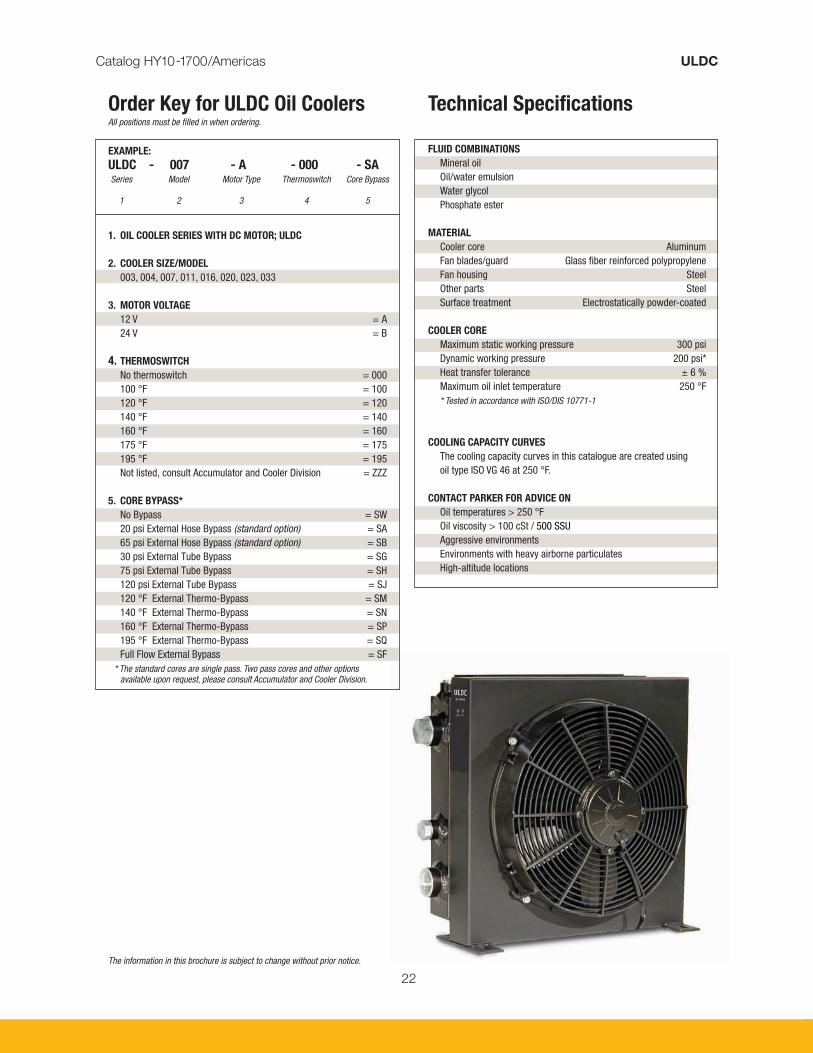
The ULDC oil cooler with 12 or 24V DC motor is
optimized for use in the mobile industry. Together
with a wide range of accessories, the ULDC cooler
is suitable for installation in most applications and
environments.
• Optimized design with right choice of
materials and components ensures a reliable
and long lasting cooler with low service and
maintenance costs.
• Compact design resulting in lighter weight
unit yet with higher cooling capacity and
lower pressure drop.
• Easy to maintain and easy to retrofit into
many applications.
• DC motor 12V/24V.
• Quiet fan and fan motor.
Catalog HY10-1700/Americas ULDC
20
Catalog HY10-1700/Americas ULDC
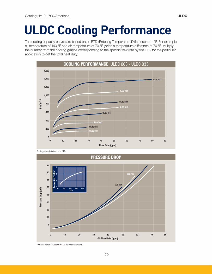
The cooling capacity curves are based on an ETD (Entering Temperature Difference) of 1 °F. For example,
oil temperature of 140 °F and air temperature of 70 °F yields a temperature difference of 70 °F. Multiply
the number from the cooling graphs corresponding to the specific flow rate by the ETD for the particular
application to get the total heat duty.
ULDC Cooling Performance
Cooling capacity tolerance ± 10%.
* Pressure Drop Correction Factor for other viscosities.
COOLING PERFORMANCE ULDC 003 - ULDC 0331,600
1,400
1,200
1,000
800
600
400
200
0
0 10 20 30 40 50 60 70 80 90
Btu
/hr/
°F
Flow Rate (gpm)
ULDC 023
ULDC 033
ULDC 020
ULDC 016
ULDC 007
ULDC 003
ULDC 011
ULDC 004
PRESSURE DROP
Pre
ssu
re d
rop
(p
si)
Oil Flow Rate (gpm)
003, 004
007, 011
45
40
35
30
25
20
15
10
5
0 10 20 30 40 50 60 70 80
3
2
1
050 150 250 350 450
SSU
Corr
ecti
on
Fa
cto
r*

21
Catalog HY10-1700/Americas ULDC
TYPE A B C D E F G H I J K L MNø
dia./oblong
ULDC 003 8.9 2.5 3.5 - 5.2 0.9 7.8 5.3 9.6 5.8 4.6 5.9 4.1 0.35 x 0.55ULDC 004 10.0 3.5 3.5 - 6.0 0.9 9.0 5.3 10.5 5.8 5.2 6.0 4.3 0.35 x 0.55ULDC 007 13.3 3.7 6.3 3.2 8.0 0.9 11.7 8.0 13.0 10.5 6.8 6.8 4.3 0.35ULDC 011 15.6 3.4 9.0 3.2 8.0 0.9 14.3 14.2 15.7 4.0 7.9 8.5 4.9 0.35 x 1.1ULDC 016 18.3 3.4 11.7 3.2 8.0 0.9 17.0 16.4 18.3 4.0 9.3 8.3 4.8 0.35 x 1.1ULDC 020 20.1 3.0 13.8 2.8 8.0 0.9 18.7 18.5 20.1 4.0 10.1 8.3 4.9 0.35 x 0.55ULDC 023 25.0 5.4 14.9 3.2 14.0 - 20.2 - 24.2 11.4 7.9/18.0 8.6 4.9 0.51ULDC 033 26.7 3.4 19.1 3.2 14.0 1.0 24.5 - 25.0 11.4 7.9/18.0 10.1 6.5 0.51
All dimensions listed above are in inches.
* Noise level tolerance ± 3 dB(A).** ULDC-023 & ULDC-033 Cooler assemblies come with two fans each. The indicated max. current is for one fan only.
TYPEWeight
lbs (Approx.)Acoustic Pressure
LpA dB(A) 3 Ft.*P
SAE O-ringQ
SAE O-ring BossQ
SAE O-Ring BossULDC 003 11 68 9 3 1" (#16)ULDC 004 13 63 7 4 1" (#16)ULDC 007 20 71 13 6 1" (#16)ULDC 011 26 75 20 12 1" (#16)ULDC 016 33 75 20 12 1" (#16)ULDC 020 40 82 20 10 1" (#16)ULDC 023 55 75 20 12 1" (#16)ULDC 033 66 75 20 12 1¼" (#20)
Max. Current (Amps.)**
12 Volts 24 Volts
22
Catalog HY10-1700/Americas ULDC
Technical Specifications
FLUID COMBINATIONS
Mineral oil Oil/water emulsion Water glycol Phosphate ester
MATERIAL
Cooler core AluminumFan blades/guard Glass fiber reinforced polypropyleneFan housing SteelOther parts SteelSurface treatment Electrostatically powder-coated
COOLER CORE
Maximum static working pressure 300 psiDynamic working pressure 200 psi*Heat transfer tolerance ± 6 %Maximum oil inlet temperature 250 °F* Tested in accordance with ISO/DIS 10771-1
COOLING CAPACITY CURVES
The cooling capacity curves in this catalogue are created using oil type ISO VG 46 at 250 °F.
CONTACT PARKER FOR ADVICE ON
Oil temperatures > 250 °FOil viscosity > 100 cSt / 500 SSUAggressive environmentsEnvironments with heavy airborne particulatesHigh-altitude locations
Order Key for ULDC Oil CoolersAll positions must be filled in when ordering.
EXAMPLE:
ULDC - 007 - A - 000 - SA Series Model Motor Type Thermoswitch Core Bypass 1 2 3 4 5
1. OIL COOLER SERIES WITH DC MOTOR; ULDC
2. COOLER SIZE/MODEL
003, 004, 007, 011, 016, 020, 023, 033
3. MOTOR VOLTAGE
12 V = A24 V = B
4. THERMOSWITCH
No thermoswitch = 000100 °F = 100120 °F = 120140 °F = 140160 °F = 160 175 °F = 175195 °F = 195Not listed, consult Accumulator and Cooler Division = ZZZ
5. CORE BYPASS*
No Bypass = SW20 psi External Hose Bypass (standard option) = SA65 psi External Hose Bypass (standard option) = SB30 psi External Tube Bypass = SG75 psi External Tube Bypass = SH120 psi External Tube Bypass = SJ120 °F External Thermo-Bypass = SM140 °F External Thermo-Bypass = SN160 °F External Thermo-Bypass = SP 195 °F External Thermo-Bypass = SQFull Flow External Bypass = SF
* The standard cores are single pass. Two pass cores and other optionsavailable upon request, please consult Accumulator and Cooler Division.
The information in this brochure is subject to change without prior notice.

23
ULHC With Hydraulic Motor For mobile and industrial use – maximum cooling capacity 215 HP
The ULHC oil cooler with hydraulic motor is
optimized for use in the mobile and industrial
sector. Together with a wide range of accessories,
the ULHC cooler is suitable for installation in most
applications and environments.
• Optimized design with right choice
of materials and components ensures
a reliable and long lasting cooler with
low service and maintenance costs.
• Compact design resulting in lighter
weight unit yet with higher cooling
capacity and lower pressure drop.
• Easy to maintain and easy to retrofit
into many applications.
• Hydraulic motor with displacement from
8.4 cc/rev to 25.2 cc/rev.
• Collar bearing for fan motor on larger
models provides longer operating life.
• Quiet fan design due to optimization
of material and blade design.
• Cooler core with low pressure drop
and high cooling capacity.
Catalog HY10-1700/Americas ULHC

24
COOLING PERFORMANCE ULHC 033 - ULHC 112
The cooling capacity curves are based on an ETD (Entering Temperature Difference) of 1 °F. For example,
oil temperature of 140 °F and air temperature of 70 °F yields a temperature difference of 70 °F. Multiply
the number from the cooling graphs corresponding to the specific flow rate by the ETD for the particular
application to get the total heat duty.
ULHC Cooling PerformanceCatalog HY10-1700/Americas ULHC
Btu
/hr/
°F
Flow Rate (gpm)
ULHC 112, 1,000 rpm
ULHC 112, 750 rpm
ULHC 078, 1,000 rpm
ULHC 078, 750 rpmULHC 058, 1,000 rpmULHC 058, 750 rpmULHC 044, 1,500 rpm
ULHC 044, 1,000 rpm
ULHC 033, 1,000 rpmULHC 033, 1,500 rpm
7,000
6,000
5,000
4,000
3,000
2,000
1,000
00 20 40 60 80 100 120 140
COOLING PERFORMANCE ULHC 007 - ULHC 0231,600
1,400
1,200
1,000
800
600
400
200
0
0 10 20 30 40 50 60
ULHC 023, 1,500 rpm
ULHC 016, 3,000 rpm
ULHC 023, 1,000 rpmULHC 016, 1,500 rpm
ULHC 011, 3,000 rpm
ULHC 011, 1,500 rpm
ULHC 007, 3,000 rpm
ULHC 007, 1,500 rpm
Btu
/hr/
°F
Flow Rate (gpm)

25
Catalog HY10-1700/Americas ULHC
PRESSURE DROP
50
40
30
20
10
0
0 20 40 60 80 100 120
Pre
ssu
re d
rop
at
150 S
SU
(p
si)
Oil Flow Rate (gpm)
007, 011
016,023033 044
058, 078, 112
Corr
ecti
on
Fa
cto
r*
3
2
1
050 150 250 350 450
SSU
* Pressure Drop Correction Factor for other viscosities.

26
TYPE Fan Speed
rpmFan Power
HPWeight
lbs. (Approx.)Max Speed
rpm
Acoustic Pressure
Level
LpA dB(A) 3 Ft*ULHC 007 1,500 0.13 22 3,500 62
3,000 0.87 22 3,500 79ULHC 011 1,500 0.27 33 3,500 67
3,000 2.01 33 3,500 82ULHC 016 1,500 0.13 40 3,500 60
3,000 0.47 40 3,500 70ULHC 023 1,000 0.20 66 2,840 64
1,500 0.67 66 2,840 76ULHC 033 1,000 0.87 88 2,350 75
1,500 2.68 88 2,350 85ULHC 044 1,000 0.94 123 2,350 77
1,500 2.68 123 2,350 86ULHC 058 750 1.01 170 1,850 75
1,000 2.41 170 1,850 83ULHC 078 750 0.94 245 1,690 81
1,000 2.15 245 1,690 88ULHC 112 750 2.28 276 1,440 86
1,000 5.36 276 1,440 92
MOTOR Displacement
cm 3/rN
ULHC 007 - ULHC 023N
ULHC 033 - ULHC 112Max. Working Pressure
psiA 8.4 4.5 6.1 3,000B 10.8 4.8 6.3 3,000C 14.4 4.9 6.6 3,000D 16.8 5.0 6.7 3,000E 19.2 5.2 6.9 3,000F 25.2 5.6 7.4 2,330
Catalog HY10-1700/Americas ULHC
* Noise level tolerance ± 3 dB(A).

27
TYPE A B C D E F G H I J K
ULHC 007 5.2 6.3 3.2 8.0 0.2 11.7 15.6 8.0 14.4 20.1 7.8ULHC 011 5.4 9.0 3.2 8.0 0.1 14.3 18.5 8.0 17.3 20.1 9.2ULHC 016 5.1 11.7 3.2 8.0 0.3 17.0 20.7 8.0 19.5 20.1 11.6ULHC 023 5.2 14.9 3.2 14.0 0.2 20.2 24.0 14.0 22.8 20.1 12.0ULHC 033 5.2 19.1 3.2 14.0 - 24.5 28.4 14.0 27.2 20.1 14.2ULHC 044 4.6 26.1 3.2 14.0 - 31.5 34.1 14.0 27.2 20.1 17.0ULHC 058 5.2 26.1 3.2 20.0 - 31.5 35.4 20.0 34.2 20.1 17.6ULHC 078 5.2 32.3 3.9 26.8 - 38.9 41.4 20.4 40.2 24.0 20.7ULHC 112 5.1 38.8 3.9 31.1 0.2 45.4 47.8 23.6 46.7 24.0 23.9
TYPEL
(Max) MP
SAE O-ringQ
SAE O-ring Boss Motor Selection
ULHC 007 14.4 8.9 ½" (#8) 1" (#16) A - FULHC 011 15.3 9.8 ½" (#8) 1" (#16) A - FULHC 016 16.3 10.8 ½" (#8) 1" (#16) A - FULHC 023 16.6 11.1 ½" (#8) 1" (#16) A - FULHC 033 19.7 12.5 ½" (#8) 1¼" (#20) A - FULHC 044 20.7 13.5 ½" (#8) 1¼" (#20) A - FULHC 058 22.4 15.3 ¾" (#12) 1½" (#24) A - FULHC 078 21.4 16.3 ¾" (#12) 1½" (#24) B - FULHC 112 24.4 17.2 ¾" (#12) 1½" (#24) D - F
All dimensions listed above are in inches.
Catalog HY10-1700/Americas ULHC

28
Technical Specifications
FLUID COMBINATIONS
Mineral oil Oil/water emulsion Water glycol Phosphate ester
MATERIAL
Cooler core AluminumFan blades/Housing Glass fiber reinforced polypropylene/
AluminumFan housing SteelFan guard SteelOther parts SteelSurface treatment Electrostatically powder-coated
COOLER CORE
Maximum static operating pressure 300 psiDynamic operating pressure 200 psi*Heat transfer tolerance ± 6 %Maximum oil inlet temperature 250 °F
* Tested in accordance with ISO/DIS 10771-1
COOLING CAPACITY CURVES
The cooling capacity curves in this catalog are being created using oil type ISO VG 46 at 140 °F.
CONTACT PARKER FOR ADVICE ON
Oil temperatures > 250 °FOil viscosity > 100 cSt / 500 SSUAggressive environmentsEnvironments with heavy airborne particulatesHigh-altitude locations
Order Key for ULHC Oil CoolersAll positions must be filled in when ordering.
EXAMPLE:
ULHC - 007 - A - 120 - SA Series Model Hydraulic motor Thermoswitch Core Bypass displacement 1 2 3 4 5
1. OIL COOLER SERIES WITH HYDRAULIC MOTOR; ULHC
2. COOLER SIZE/MODEL
007, 011, 016, 023, 033, 044, 058, 078 and 112.
3. HYDRAULIC MOTOR, DISPLACEMENT
No hydraulic motor = WDisplacement 8.4 cm3/rev. = ADisplacement 10.8 cm3/rev. = BDisplacement 14.4 cm3/rev. = CDisplacement 16.8 cm3/rev. = DDisplacement 19.2 cm3/rev. = EDisplacement 25.2 cm3/rev. = FNot listed, consult Accumulator and Cooler Division = Z
4. THERMO CONTACT
No thermoswitch = 000100 °F = 100120 °F = 120140 °F = 140160 °F = 160 175 °F = 175195 °F = 195Not listed, consult Accumulator and Cooler Division = ZZZ
5. CORE BYPASS*
No Bypass = SW20 psi External Hose Bypass (standard option) = SA65 psi External Hose Bypass (standard option) = SB30 psi External Tube Bypass = SG75 psi External Tube Bypass = SH120 psi External Tube Bypass = SJ120 °F External Thermo-Bypass = SM140 °F External Thermo-Bypass = SN160 °F External Thermo-Bypass = SP 195 °F External Thermo-Bypass = SQFull Flow External Bypass = SF
* The standard cores are single pass. Two pass cores and other options available upon request, please consult Accumulator and Cooler Division.
The information in this brochure is subject to change without prior notice.
Catalog HY10-1700/Americas ULHC

29
OAW Water Oil Cooler For mobile and industrial use
The OAW oil cooler is optimized for use in mobile
and industrial sectors. Together with a wide range
of accessories, the OAW cooler is suitable for
installation in most applications and environments.
• Optimized design and the right choice of
materials and components ensure reliable
and long-lasting cooling with low service
and maintenance costs.
• Compact design for easy installation.
• Turbulent water flow prevents clogging
and reduces maintenance.
• Low water consumption for economical
operation.
• SAE O-ring connections for ease of
assembly and leak-proof operation.
• Maximum material efficiency with no
“Dead Zone.”
Catalog HY10-1700/Americas OAW

30
GeneralCatalog HY10-1700/Americas OAW
Our OAW coolers are designed for a maximum working pressure of 450 psi. The most standard application for
the OAW cooler involves a cold water circuit and a hot oil circuit. Fluids are not limited to oil and water however;
see the Fluid Compatibility section in the OAW product literature for more information. Inlets and outlets are
clearly identified by the Accumulator and Cooler Division sticker affixed to the front of the unit. When in doubt,
pour a liquid in one of the connections and note which connection it comes out of. This will be the inlet and
outlet for one circuit (either oil or water). The other inlet should be located on the diagonal from the first inlet.
Maximum cooling efficiency is achieved by cross flowing through the plates, the oil inlet and water inlet being
located on a diagonal.
Extremely Compact:
85-90% Reduction in volume
and weight of a shell-and-tube
heat exchanger of the
same capacity.
Corrugated:
Plates made of 316 stainless
steel brazed with pure copper.
Maximum Efficiency:
Maximum material efficiency.
No “Dead Zone” because there
is no need for gaskets. Up to
25% more capacity utilization.
SAE O-Ring Connections:
Good for ease of assembly and
leak proof operation.
LOW WATER
CONSUMPTION.
ECONOMICAL
OPERATION COMPACT.
TURBULENT WATER FLOW
PREVENTS CLOGGING AND
REDUCES MAINTENANCE.
SMALLER SIZE MAKES IT
EASY TO INSTALL.
BROAD RANGE:
SEVERAL MODELS
IN-STOCK FOR
IMMEDIATE DELIVERY.
OAW to the max.

31
Catalog HY10-1700/Americas OAW
OAW 14 & OAW 34
MODELCooling Capacity
(*hp) ConnectionA
(inches)Weight
(lbs.)Volume
(in3)OAW 14-10-SG 2-7 5/8" SAE O-ring 1.4 1.4 15OAW 34-20 6-33 1" SAE O-ring 2.3 9 74OAW 34-40 20-69 1" SAE O-ring 4.1 15 149
2.9" 0.8"A
1.6"
7.4"
OilOutlet
OilInlet
WaterInlet
WaterOutlet
6.1"
4.7" 1.1"A
2.8"
11.4"
OilOutlet
OilInlet
WaterInlet
WaterOutlet
9.6"
*Cooling capacity is calculated with the following conditions. For other flow conditions, type of fluids or temperatures, please see page 35 or consult Accumulator and Cooler Division. Oil type – ISO VG 32 – Oil/water flow ratio – 2:1 – Oil inlet temperature – 140°F – Water inlet temperature – 80°F
30
25
20
15
10
5
00 5 10 15 20 25 30 35 40 45 50 55
Pre
ssu
re D
rop
(p
si)
Oil Flow Rate (gpm)
14-10 34-20 34-40
OAW 14 & 34 PRESSURE DROPOAW 14 & 34 COOLING CAPACITY
70
60
50
40
30
20
10
00 5 10 15 20 25 30 35 40 45 50 55
Hea
t D
issip
ati
on
(h
p)
Oil Flow Rate (gpm)
14-10
34-20
34-40

32
Catalog HY10-1700/Americas OAW
OAW 46 & OAW 61
MODELCooling Capacity
(*hp) ConnectionA
(inches)Weight
(lbs.)Volume
(in3)OAW 46-40 21-94 1¼" SAE O-ring 3.9 13 200OAW 46-60 23-142 1¼" SAE O-ring 5.7 18 300OAW 61-40 27-98 1¼" SAE O-ring 3.9 19 271OAW 61-60 53-152 1¼" SAE O-ring 5.7 27 406OAW 61-80 79-198 1¼" SAE O-ring 7.4 34 542
4.8"
1.1"A2.5"
14.9"
OilOutlet
OilInlet
WaterInlet
WaterOutlet
12.6"
4.8"
1.1"A2.5"
20.8"
OilOutlet
OilInlet
WaterInlet
WaterOutlet
18.5"
0 10 20 30 40 50 60 70 80 90
Oil Flow Rate (gpm)
*Cooling capacity is calculated with the following conditions. For other flow conditions, type of fluids or temperatures, please see page 35 or consult Accumulator and Cooler Division. Oil type – ISO VG 32 – Oil/water flow ratio – 2:1 – Oil inlet temperature – 140°F – Water inlet temperature – 80°F
200
180
160
140
120
100
80
60
40
20
0
Hea
t D
issip
ati
on
(h
p)
61-40
61-80
46-40
46-40
61-80
OAW 46 & 61 COOLING CAPACITY OAW 46 & 61 PRESSURE DROP
35
30
25
20
15
10
5
00 20 40 60 80 100 120
Pre
ssu
re d
rop
(p
si)
Oil Flow Rate (gpm)
61-4046-40 61-50
46-60
61-80

33
Catalog HY10-1700/Americas OAW
MODELCooling Capacity
(*hp) ConnectionA
(inches)Weight
(lbs.)Volume
(in3)OAW 95-40 50-150 1½" SAE O-ring 4.1 44 427OAW 95-60 63-171 1½" SAE O-ring 6.0 59 641OAW 126-60 84-259 1½" SAE O-ring 6.1 79 856OAW 126-80 138-274 1½" SAE O-ring 7.9 97 1142
9.6"
5.51"
2.8"
3.94"
5.0"
1.1"A6.9"
15.5"
OilOutlet
OilInlet
WaterInlet
WaterOutlet
12.8"
4x½" UNC
9.6"
1.1"A6.9"
20.7"
OilOutlet
OilInlet
WaterInlet
WaterOutlet
18.0" 5.51"
2.8"
7.6"
3.94"
4x½" UNC
OAW 95 & OAW 126
*Cooling capacity is calculated with the following conditions. For other flow conditions, type of fluids or temperatures, please see page 35 or consult Accumulator and Cooler Division. Oil type – ISO VG 32 – Oil/water flow ratio – 2:1 – Oil inlet temperature – 140°F – Water inlet temperature – 80°F
Hea
t D
issip
ati
on
(h
p)
OAW 95 & 126 COOLING CAPACITY
275
250
225
200
175
150
125
100
75
50
25
0 0 20 40 60 80 100 120
Oil Flow Rate (gpm)
126-80
126-60
95-60
95-40
OAW 95 & 126 PRESSURE DROP
35
30
25
20
15
10
5
00 20 40 60 80 100 120 140
Pre
ssu
re d
rop
(p
si)
Oil Flow Rate (gpm)
126-60
126-80
95-60
95-40

34
Catalog HY10-1700/Americas OAW
InstallationInstallation Instructions for OAW Coolers
The OAW coolers are designed for a maximum
working pressure of 450 psi. The most standard
application for the OAW cooler involves a cold water
circuit and a hot oil circuit. Fluids are not limited to
oil and water however; for other types of fluid, please
contact the factory.
Inlets and outlets are clearly identified by the
Accumulator and Cooler Division sticker affixed to the
front of the unit. When in doubt, pour a liquid in one of
the connections and note which connection it comes
out of. This will be the inlet and outlet for one circuit
(either oil or water). The other inlet should be located
on the diagonal from the first inlet.
When to Clean
Fouling occurs mainly on the water side of the cooler.
Fouling can be detected by monitoring the inlet and
outlet temperatures and/or the pressure drop across
the cooler. Fouling will result in decreased heat
transfer, producing temperature differences lower
than specified.
Fouling also restricts the passages and thus causes
an increase in velocity. This will produce an increase
in the pressure drop across the cooler. When either
the temperature difference or the pressure drop is
significantly different from specified values, cleaning
should be performed.
Methods of Cleaning
If cleaning the cooler is required, backflushing with
water will remove most of the soft deposits. If fouling
appears in the form of hard deposits, circulate a weak
acid through the cooler in reverse direction to normal
water flow. Use 5% phosphoric acid for infrequent
cleanings. For more frequent cleaning, use 5% oxalic
acid or similar weak organic acid. Afterwards flush
with a large quantity of water to remove all acid
from the cooler before starting up the system again.
Never wait until the cooler is completely clogged
before cleaning!
Filters or Strainers
When there are particles in the fluid that could clog
the cooler, filters or strainers should be used. Particles
up to 1mm diameter will not cause any problems.
Fluid Compatibility
On the oil side, most synthetic and petroleum
based fluids may be used. For aggressive oils,
please contact Accumulator and Cooler Division
for compatibility. On the water side, de-mineralized
and untreated water may be used without concern.
When water is chemically treated please contact
Accumulator and Cooler Division for suitability.
Sea water cannot be used in OAW coolers. For
sea water applications, please contact Accumulator
and Cooler Division on information on titanium
coolers. Do not use ammonia in the OAW coolers.
Maximum cooling efficiency is achieved by cross
flowing through the plates, the oil inlet and water
inlet being located on a diagonal. Failure to have the
cooler attached in this manner will lead to a decrease
in efficiency.
The cooler may be mounted in any position. However,
requirements for draining the circuits should be taken
into consideration.
The OAW coolers must not be installed into a rigid
frame. Use the Accumulator and Cooler Division
purpose-made brackets (or “Armaflex” equivalent) to
provide a “soft, elastic installation.” The OAW 95 and
126 series coolers come equipped with stud bolts to
assist in mounting. However, these bolts alone should
not be used to suspend the cooler. All tubing should
be done in such a way as to minimize vibrations to
the cooler. When installed on a return line, the cooler
should be connected using flexible hoses.
Outlet A Inlet B
Inlet A Outlet B

35
Catalog HY10-1700/Americas OAWCatalog HY10-1700/Americas OAW
Correction Factors for Other Oil Types,
Temperatures and Flow Rates
All of the cooling curves are based on very specific
conditions. These include using an ISO VG 32 oil,
having an oil/water ratio of 2:1, and having an oil/
water inlet difference of 60 °F. For other conditions,
the following correction factors should be used.
Correction Factors for Other Oil Types
Cooling Capacity: Multiply the requested cooling
capacity with the correction factor Kv.
Oil Pressure Drop: Multiply the pressure drop with
the correction factor Kp.
Correction Factors for Other Inlet
Temperature Differences
Cooling Capacity: For inlet temperature differences
other than 60 °F, multiply the requested cooling
capacity by the correction factor Kt.
Correction Curves for Other Oil/Water
Flow Ratios
Cooling Capacity: For all other oil/water flow ratios
other than 2:1, divide the requested cooling capacity
by the factor Kr obtained from the curves in Graph 3.
Sizing Example
Conditions:
Oil type: ISO VG 68
Oil Flow: 40 gpm
Desired cooling capacity Qr 40 hp
Oil temperature in To 140 °F
Water temperature in Tw 100 °F
Available water flow 10 gpm
Maximum Pressure Drop 30 psi
ETD = To - Tw = 140°F - 100°F = 40°F
The design cooling capacity (Qd) is the cooling
capacity used when selecting a suitable cooler. Qd
is calculated by multiplying Qr by the factors Kv and
Kt (found in Tables 1 and 2 respectively) and then
dividing by the Kr factor found from Graph 3.
Qd = Qr x Kv x Kt = 40 hp x 1.2 x 1.43 = 83 hp
Kr 0.82
According to the cooling capacity curves on page
32, the minimum size cooler for these conditions is
an OAW 61-40.
The oil pressure drop can be found from the
pressure drop curve. It should be multiplied by the
Pressure Drop Factor, Kp from Table 1.
DPoil = p x Kp = 23 psi x 1.7 = 39.1 psi.
In this case the pressure drop exceeds the
maximum allowable. The next size cooler would
be an: OAW 61-60
The pressure drop for this cooler would be:
DPoil = p x Kp = 12 psi x 1.7 = 20.4 psi.
Therefore the correct size cooler would be the
OAW 61-60.
For assistance with calculations, please contact
Accumulator and Cooler Division.
Viscocity ClassCooling Capacity
Factor, Kv
Pressure Drop
Factor, Kp
ISO VG 22 0.95 0.9ISO VG 32 1.0 1.0ISO VG 46 1.05 1.3ISO VG 68 1.2 1.7ISO VG 100 1.35 2.2ISO VG 150 1.6 3.0ISO VG 220 1.9 4.3
Table 1
ETD 30 40 50 60 70
Kt 1.87 1.43 1.17 1.0 0.88
Table 2
Kr
X/1 Oil/Water
1.10
1.05
1.00
0.95
0.90
0.85
0.80
0.751 2 3 4 5
OAW 61 & 126
OAW 34 & 95
Graph 3
OAW 14
OAW 46

36
Notes

37
Catalog HY10-1700/Americas
Supplementing a hydraulic system with a cooler and proper accessories or an accumulator gives you increased system up time and a longer expected life as well as lower service and repair costs. All applications and operating environments
Take the next stepChoose the right accessories
Pressure-controlled bypass valve Integrated
Allows the oil to bypass the cooler
core if the pressure drop is too
high. Reduces the risk of the cooler
bursting, e.g. in connection with
cold starts and temporary peaks in
pressure or flow. Available for single-
pass or two-pass core design.
Temperature-controlled bypass valve Integrated
Same function as the pressure-
controlled by-pass valve, but
with a temperature-controlled
opening pressure – the hotter
the oil, the higher the opening
pressure. Available for single-pass
or two-pass core design.
Thermo contact
Sensor with fixed set point for
temperature warnings and cost
efficient operation with automatic
switching on and off of the fan
motor thereby reducing the
energy usage.
Temperature-controlled 3-way valve External
Same function as the
temperature-controlled bypass
valve, but positioned externally.
Note: Must be ordered separately.
Smart DC Drive speed regulation
For cost-efficient operation and
better environmental consideration
through speed regulated fan control –
the higher the temperature, the
higher the fan speed.
Stone guard/Dust guard
Protects components and
systems from tough conditions.
are unique. A well-planned choice of the following accessories can thus further improve your hydraulic system. Please contact Accumulator and Cooler Division for guidance and information.
Lifting eyes
For simple installation
and relocation.

38
A close collaboration between our application engineers, designers and you as the customer during the whole project will result in a high-quality product. The final product will be a tailor-made cooler, which always meets your unique needs.
Extensive choicesLong-term experience from the mobile field has provided us with a unique ability to deliver the
ideal combination cooler solution. Depending on the conditions, the cooler fan can be operated by the diesel engine on the machine or by a hydraulic motor or a DC motor. We can also supply many different cooler combination options. A frequent combination is the “side-by-side”-cooler, where the coolers are placed side-by-side, no matter the media, such as a water cooler, an oil cooler and an intercooler. Another solution is
the “sandwich”-cooler, where the coolers are placed in front of each other. The solution could also be a combination of these two. No matter which combination will be used, the pressure drop and the heat dissipation across the core will always be optimal.
Cooling Modules/ Combination CoolerProviding optimal solutions
Professional competence, as well as advanced technology and extensive knowledge from the industry,
allow us to provide many cooler combinations, which meet your unique needs.
Catalog HY10-1700/Americas

AerospaceKey MarketsAftermarket services
Commercial transports
Engines
General & business aviation
Helicopters
Launch vehicles
Military aircraft
Missiles
Power generation
Regional transports
Unmanned aerial vehicles
Key ProductsControl systems & actuation products
Engine systems & components
Fluid conveyance systems& components
Fluid metering, delivery
& atomization devices
Fuel systems & components
Fuel tank inerting systems
Hydraulic systems
& components
Thermal management
Wheels & brakes
AutomationKey Markets Renewable energy
Conveyor & material handling
Factory automation
Food & beverage
Life sciences & medical
Machine tools
Packaging machinery
Paper machinery
Plastics machinery
Primary metals
Safety & security
Semiconductor & electronics
Transportation & automotive
Key Products AC/DC drives & systems
Air preparation
Electric actuators, gantryrobots & slides
Human machine interfaces
Inverters
Manifolds
Miniature fluidics
Pneumatic actuators & grippers
Pneumatic valves & controls
Rotary actuators
Stepper motors, servo motors,
drives & controls
Structural extrusions
Vacuum generators, cups & sensors
Fluid ConnectorsKey Markets
Aerial lift
Agriculture
Bulk chemical handling
Construction machinery
Food & beverage
Fuel & gas delivery
Industrial machinery
Life sciences
Marine
Mining
Mobile
Oil & gas
Renewable energy
Transportation
Key Products Check valves
Connectors for low pressure fluid conveyance
Deep sea umbilicals
Diagnostic equipment
Hose couplings
Industrial hose
Mooring systems & power cables
PTFE hose & tubing
Quick couplings
Rubber & thermoplastic hose
Tube fittings & adapters
Tubing & plastic fittings
HydraulicsKey Markets Aerial lift
Agriculture
Alternative energy
Construction machinery
Forestry
Industrial machinery
Machine tools
Marine
Material handling
Mining
Oil & gas
Power generation
Refuse vehicles
Renewable energy
Truck hydraulics
Turf equipment
Key Products Accumulators
Cartridge valves
Electrohydraulic actuators
Human machine interfaces
Hybrid drives
Hydraulic cylinders
Hydraulic motors & pumps
Hydraulic systems
Hydraulic valves & controls
Hydrostatic steering
Integrated hydraulic circuits
Power take-offs
Power units
Rotary actuators
Sensors
InstrumentationKey Markets Alternative fuels
Biopharmaceuticals
Chemical & refining
Food & beverage
Marine & shipbuilding
Medical & dental
Microelectronics
Nuclear Power
Offshore oil exploration
Oil & gas
Pharmaceuticals
Power generation
Pulp & paper
Steel
Water/wastewater
Key ProductsAnalytical Instruments
Analytical sample conditioningproducts & systems
Chemical injection fittings& valves
Fluoropolymer chemicaldelivery fittings, valves & pumps
High purity gas delivery fittings, valves, regulators& digital flow controllers
Industrial mass flow meters/controllers
Permanent no-weld tube fittings
Precision industrial regulators& flow controllers
Process control double block & bleeds
Process control fittings, valves, regulators & manifold valves
SealKey Markets Aerospace
Chemical processing
Consumer
Fluid power
General industrial
Information technology
Life sciences
Microelectronics
Military
Oil & gas
Power generation
Renewable energy
Telecommunications
Transportation
Key Products Dynamic seals
Elastomeric o-rings
Electro-medical instrumentdesign & assembly
EMI shielding
Extruded & precision-cut,
fabricated elastomeric seals
High temperature metal seals
Homogeneous & insertedelastomeric shapes
Medical device fabrication & assembly
Metal & plastic retainedcomposite seals
Shielded optical windows
Silicone tubing & extrusions
Thermal management
Vibration dampening
Parker’s Motion & Control Product GroupsAt Parker, we’re guided by a relentless drive to help our customers become more productive and achieve higher levels of profitabil-ity by engineering the best systems for their require-ments. It means looking at customer applications from many angles to find new ways to create value. What-ever the motion and control technology need, Parker has the experience, breadth of product and global reach to consistently deliver. No company knows more about motion and control technol-ogy than Parker. For further info call 1 800 C-Parker (1 800 272 7537)
Climate & Industrial ControlsKey Markets
Agriculture
Air conditioning
Construction Machinery
Food & beverage
Industrial machinery
Life sciences
Oil & gas
Power Generation
Process
Refrigeration
Transportation
Key Products Accumulators
Advanced actuators
CO2 controls
Electronic controllers
Filter driers
Hand shut-off valves
Heat exchangers
Hose & fittings
Pressure regulating valves
Refrigerant distributors
Safety relief valves
Smart pumps
Solenoid valves
Thermal management systems
Thermostatic expansion valves
FiltrationKey MarketsAerospace
Food & beverage
Industrial plant & equipment
Life sciences
Marine
Mobile equipment
Oil & gas
Power generation
Process
Transportation
Water Purification
Key Products Analytical gas generators
Compressed air filters & dryers
Engine air, coolant, fuel & oil filtration systems
Fluid condition monitoring systems
Hydraulic & lubrication filters
Hydrogen, nitrogen & zero
air generators
Instrumentation filters
Membrane & fiber filters
Microfiltration
Sterile air filtration
Water desalination & purification filters & systems

HY10-1700/Americas 12/2013© 2013 Parker Hannifin Corporation
Parker Hannifin CorporationAccumulator & Cooler Division - Americas
10711 N Second StreetRockford, IL 61115phone 815 636 4100fax 815 636 4111www.parker.com