ohg3067 home gym - gym equipment perth, fitness equipment ... · ohg3067 home gym . 1 parts list...
TRANSCRIPT

OHG3067 HOME GYM
1
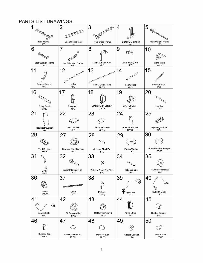
PARTS LIST DRAWINGS
2
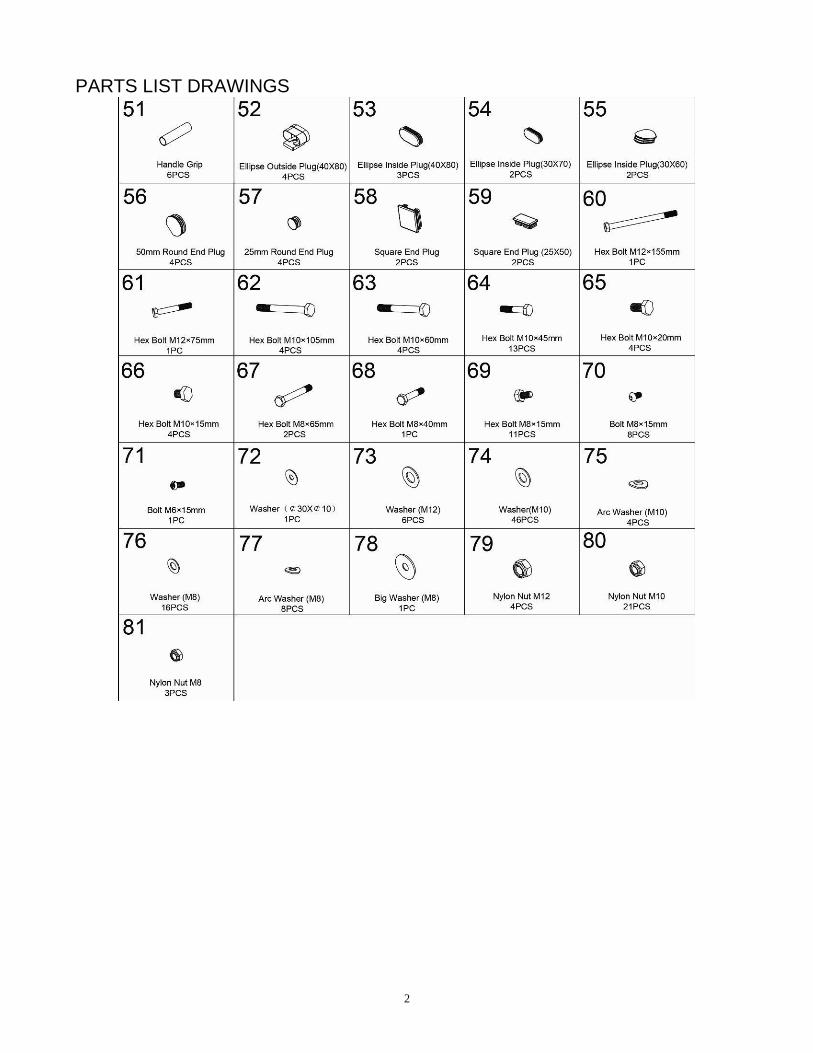
PARTS LIST DRAWINGS

3
ASSEMBLY INSTRUCTIONS
STEP 1 1. Secure Base Frame (1) with Back Base Frame (2), using two M10X105mm Hex
Bolt (62), four M10 Arc Washers (75) and two M10 Nylon Nuts (80). 2. Remove two M10X25mm Hex Bolts (65) and two M10 Washers (74) from two Weight Guide
Tubes (13). 3. Insert two Weight Guide Tubes (13) into Back Base Frame (2) using two M10X25mm Hex
Bolts (65) and two M10 Washers (74) secure it. 4. Slide two Round Rubber Bumpers (30) onto two Weight Guide Tubes (13).

4
ASSEMBLY INSTRUCTIONS
STEP2: 1. Slide nine Weight Plates (26) down two Weight Guide Tubes (13). 2. Slide Selector Shaft Bushing (27) down Selector Shaft (15) at first hole and fix with Selector
Shaft Pin (28). 3. Insert Selector Shaft (15) into hole of Weight Plate (26). 4. Slide Top Weight Plate (25) down Weight Guide Tubes (13), Insert Weight Selector Pin (32)
into hole of your desired weight. 5. Slide Plastic Washer (29) to Top Weight Plate (25).

5
ASSEMBLY INSTRUCTIONS
STEP 3: 1. Attach Main Upright Frame (5) to Base Frame (1) using two M10X105mm Hex Bolts (62),
four M10 Washers (74) and two Nylon Nuts (80). 2. Remove two M10X25mm Hex Bolts (65) and two M10 Washers (74) from two Weight Guide
Tubes (13). 3. Attach Top Cross Frame (3) to two Weight Guide Tubes (13) using two M10X20mm Hex
Bolts (65) and two M10 Washers (74). 4. Attach Top Cross Frame (3) to Main Upright Frame (5) using two M10X60mm Hex Bolts
(63), four M10 Washers (74) and two M10 Nylon Nuts (80).

6
ASSEMBLY INSTRUCTIONS
STEP 4: 1. Attach Support Frame (11) to Main Upright Frame (5) using two M10X15mm Hex Bolts (66)
and two M10 Washers (74). 2. Attach Seat Cushion Frame (6) to Main Upright Frame (5) and Support Frame (11) using
two M10X60mm Hex Bolt (63), two M10X15mm Hex Bolts (66), six M10 Washers (74) and two M10 Nylon Nuts (80).

7
ASSEMBLY INSTRUCTIONS
STEP 5: 1. Attach Butterfly Extension (4) to Top Cross Frame (3), using two Oil Bushing (small) (43),
one M12×155mm Hex Bolt (60), two M12 Washers (73) and one M12 Nylon Nut (79). 2. Attach Tobacco-pipe (34) to Main Upright Frame (5) using one M8×40mm Hex Bolt (68), two
M8 Washers (76) and one M8 Nylon Nut (81).
3. Slide ∅30X∅10 Washer (72) and Plum Blossom Nut (35) onto Tobacco-pipe (34).
4. Attach Left Butterfly Arm(9) to Butterfly Extension (4) using two Oil Bushings (big) (42), one M12 Washer (73), one M12 Nylon Nut (79) and one Plastic Dome Cap (47).
5. Insert L-Pin (31) into Butterfly Extension (4) and Left Butterfly Arm (9). 6. Slide Arm Foam Roller (24) onto Left Butterfly Arm (9). 7. Insert Hand Tube (10) into Left Butterfly Arm (9) using four M8×15mm Bolts (70) and four
M8 Arc Washers (77). 8. Assembly Right Butterfly Arm (8) with same method.

8
ASSEMBLY INSTRUCTIONS
STEP 6: 1. Attach Leg Extension Frame (7) to Seat Cushion Frame (6), using one M12×75mm Hex
Bolts (61), two M12 Washers (73) and one M12 Nylon Nuts (79). 2. Insert two Foam Tubes (14) into Seat Cushion Frame (6) and Leg Extension Frame (7). 3. Slide four Leg Foam Rollers (23) onto two Foam Tubes (14). 4. Attach two Single Pulley Brackets (18) to Main Upright Frame (5), using two M8×65mm Hex
Bolts (67), four M8 Washers (76) and two M8 Nylon Nuts (81). 5. Attach Low Pull Seat (19) down Base Frame (1), using one M8×15mm Hex Bolt (69) and
one M8 Big Washer (78). 6. Attach Backrest Cushion (21) to Main Upright Frame (5), using six M8×15mm Hex Bolts (69)
and six M8 Washers (76). 7. Attach Seat Cushion (22) to Seat Cushion Frame (6) using four M8×15mm Hex Bolts (69)
and four M8 Washers (76).

9
ASSEMBLY INSTRUCTIONS

10
ASSEMBLY INSTRUCTIONS

11
ASSEMBLY INSTRUCTIONS STEP 7: Start with the Upper Cable (39) a.) With Upper Cable (39) in groove of Pulley (36) through the Top Cross Frame (3). b.) Install Pulley NO.1 (36) to the Top Cross Frame (3) using one M10X45mm Hex Bolt (64),
two M10 Washers (74) and one M10 Nylon Nut (80). c.) Install Pulley NO.2 (36) to the Top Cross Frame (3) using one M10X45mm Hex Bolt (64),
two M10 Washers (74) and one M10 Nylon Nut (80). d.) Install Pulley NO.3 (36) to two Pulley Patches (16) using one M10X45mm Hex Bolt (64),
two M10 Washers (74) and one M10 Nylon Nut (80). e.) Install Pulley NO.4 (36) to the Top Cross Frame (3), using one M10X45mm Hex Bolt (64),
two M10 Washers (74) and one M10 Nylon Nut (80). h.) Attach the bolt end of the Upper Cable (39) to the Selector Shaft (15) with Plastic Washer
(29).

12
ASSEMBLY INSTRUCTIONS

13
ASSEMBLY INSTRUCTIONS
STEP 8: Assembly with the Butterfly Cable (40) a.) Attach the Butterfly Cable (40) to the Left Butterfly Arm (9) and the Right Butterfly Arm (8),
using two Plastic Bushings (48). b.) Install Pulley NO.5&7 (36) to two Single Pulley Blocks (18), using two M10X45mm Hex
Bolts (64), four M10 Washers (74) and two M10 Nylon Nuts (80). c.) Install Pulley NO.6 (36) to the Reverse U (17) using one M10X45mm Hex Bolt (64), two
M10 Washers (74) and one M10 Nylon Nut (80).

14
ASSEMBLY INSTRUCTIONS

15
ASSEMBLY INSTRUCTIONS
STEP 9: Assembly the Lower Cable (41) a.) Install Pulley NO.8 (36) to the Low Pull Seat (19), using one M10X45mm Hex Bolt (64), two
M10 Washers (74) and one M10 Nylon Nut (80). b.) Install Pulley NO.9 (36) to two Pulley Patches (16), using one M10X45mm Hex Bolt (64),
two M10 Washers (74) and one M10 Nylon Nut (80). c.) Install Pulley NO.10 (36) to the Base Frame (1), using one M10X45mm Hex Bolt (64), two
M10 Washers (74) and one M10 Nylon Nut (80). d.) Install Pulley NO.11 (36) to the Reverse U (17), using one M10X45mm Hex Bolt (64), two
M10 Washers (74) and one M10 Nylon Nut (80). e.) Install Pulley NO.12 (36) to the Base Frame (1), using one M10X45mm Hex Bolt (64), two
M10 Washers (74) and one M10 Nylon Nut (80). f.) Install Pulley NO.13 (36) to the Base Frame (1), using one M10X45mm Hex Bolt (64), two
M10 Washers (74) and one M10 Nylon Nut (80). g.) Attach the end of Lower Cable (41) to the Leg Extension Frame (7) using one Pothook (38).

16
ASSEMBLY INSTRUCTIONS
STEP 10 1. Attach the Lat Bar (12) to the end of Upper Cable (39), using one Pothook (38). 2. Attach the Low Bar (20) or Ankle Strap (44) to the end of Lower Cable (41), using two
Pothooks (38) and one Chain (37).

17
EXPLODED DRAWING