officeconnect cable modem external getting started · pdf file officeconnect cable modem...
TRANSCRIPT

http://www.3com.com/
OfficeConnect Cable Modem External Getting Started Guide
Part No. 1.024.2403-00Published January 2000

3Com Corporation3800 Golf Rd.Rolling Meadows, IL60008
Copyright © 2000 3Com Corporation. All rights reserved. No part of this documentation may be reproduced in any form or by any means or used to make any derivative work (such as translation, transformation, or adaptation) without written permission from 3Com Corporation.
3Com Corporation reserves the right to revise this documentation and to make changes in content from time to time without obligation on the part of 3Com Corporation to provide notification of such revision or change.
3Com Corporation provides this documentation without warranty of any kind, either implied or expressed, including, but not limited to, the implied warranties of merchantability and fitness for a particular purpose. 3Com may make improvements or changes in the product(s) and/or the program(s) described in this documentation at any time.
If there is any software on removable media described in this documentation, it is furnished under a license agreement included with the product as a separate document, in the hard copy documentation, or on the removable media in a directory file named LICENSE.TXT or !LICENSE.TXT. If you are unable to locate a copy, please contact 3Com and a copy will be provided to you.
UNITED STATES GOVERNMENT LEGEND
If you are a United States government agency, then this documentation and the software described herein are provided to you subject to the following:
All technical data and computer software are commercial in nature and developed solely at private expense. Software is delivered as “Commercial Computer Software” as defined in DFARS 252.227-7014 (June 1995) or as a “commercial item” as defined in FAR 2.101(a) and as such is provided with only such rights as are provided in 3Com’s standard commercial license for the Software. Technical data is provided with limited rights only as provided in DFAR 252.227-7015 (Nov 1995) or FAR 52.227-14 (June 1987), whichever is applicable. You agree not to remove or deface any portion of any legend provided on any licensed program or documentation contained in, or delivered to you in conjunction with, this User Guide.
3Com, the 3Com logo, EtherLink, and OfficeConnect are registered trademarks and Connections is a trademark of 3Com Corporation.
Microsoft, Windows, and Windows NT are registered trademarks of Microsoft Corporation.
All other company and product names may be trademarks of the respective companies with which they are associated.

CONTENTS
1 BEFORE YOU BEGIN
Introduction 1
Conventions 1Cable Modem Features 1Contacting Your Local Cable Provider 2
Preparing Your Workspace 3You Will Need These Items 4
Supplied 4
You will also need the following 4Configuring the TCP/IP Protocol 5
Configuring the TCP/IP Protocol on a Windows PC 5
Configuring the TCP/IP Protocol on a Macintosh PC 7
2 HARDWARE AND SOFTWARE INSTALLATION
Wall-Mount Installation 11
Desktop Installation 13OfficeConnect Stacking Installation 14Connecting the Cable Modem to Your Computer 14
Installing the Cable ConnectionsTM CD-ROM 15
3 CABLE MODEM OPERATION
Interpreting the LEDs on the Front of Your Cable Modem 17
Connectors and Switches on the Back of Your Cable Modem 18
4 TROUBLESHOOTING AND SUPPORT RESOURCES
Troubleshooting 21I cannot access my e-mail or Internet service. 21
The Cable Status LED never stops blinking. 22All of LEDs on the front of my modem look right, but I still can't access the Internet. 22

The power on my modem goes on and off sporadically. The Cable Modem Status light never stops blinking. 23
Support Resources 23
Internet FTP 23World Wide Web 2390-Day Free Installation Support 23
Technical Support Hotline 24If You Are Still Having Problems 24If You Need to Return the Modem to Us 24
5 REGULATORY INFORMATION AND LIMITED WARRANTY
Manufacturer's Declaration of Conformity 25Part 15 25
FCC Class B Statement 25FCC Notice: Radio and Television Interference 25Caution to the User 26
Performance Specifications 26 Export Notices 26License Agreement 27
Industry Canada (IC) 27UL Listing/CUL Listing 27Radio and Television Interference 28
VCCI Statement 293Com Corporation Limited Warranty 29
Hardware 29
Software 29Year 2000 Warranty 30Obtaining Warranty Service 31
WARRANTIES EXCLUSIVE 31LIMITATION OF LIABILITY 32Disclaimer 32
Governing Law 33
6 WALL-MOUNTING TEMPLATE

1 BEFORE YOU BEGIN
IntroductionCongratulations! You have just purchased a modem featuring a pioneering new technology, making Internet access possible at speeds previously only imagined! This external cable modem is one part of a comprehensive communications system that utilizes the cable television network to deliver high-speed data to your computer. Data is requested and sent over the cable television network at burst rates of up to 38 megabits per second (Mbps). This chapter explains how to prepare your computer system for cable modem installation.
ConventionsThe following table lists the conventions used within this manual.
Cable Modem Features ■ Cable line bandwidth allows user data rates of up to 38
megabits per second (Mbps)*, faster than 56K analog modems, ISDN, or ADSL
■ Two-way design means that the cable modem sends and receives data over the cable line (unlike one-way
Icon Notice Type Description
Information note Important features or instructions
Caution Information to alert you to potential damage to a program, system, or device
Warning Information to alert you to potential personal injury

2 CHAPTER 1: BEFORE YOU BEGIN
cable modems, which require an analog modem for upstream data)
■ Plug and play operation ensures easy setup and installation
■ DOCSIS-compliance ensures interoperability with cable suppliers
■ 3Com’s extensive technical support organization provides you with the quick answers you need to get up and running
* NOTE: Please note that the following factors affect the speeds you may experience: (1) your computer equipment and configuration, including the speed of your processor, the amount of RAM on your system, and your available hard disk space; (2) applications running simultaneously with the modem which use varying amounts of your computer’s resources; (3) the capacity of the Internet service you order from your provider; (4) changing network traffic levels depending when you go online.
Contacting Your Local Cable Provider In order to use your cable modem, you need to setup an Internet access account with your local cable provider. Before contacting your cable provider to setup an account, have the following information handy:
■ The modem’s hardware revision, software revision, Ethernet address, and USB address are located on a bar code sticker on the back of the modem. Write these numbers in the following blanks.
■ Hardware revision: __________________ Software revision: __________________ Manufacuring date: __________________ Ethernet address: __________________ USB address: __________________

Preparing Your Workspace 3
You should now contact your local cable provider and verify the following:
■ The cable service to your home supports two-way cable modem access. If your cable company does not provide two-way service, this cable modem will not be able to communicate with your cable company’s Internet access service. You should immediately consult your cable company and place of purchase to determine the proper 3Com cable modem to use. You can also visit the following URL for additional information:
http://www.3com.com/cablemodem
■ Your cable provider has set up your cable Internet access account. Your cable provider will setup an Internet access account that will allow you to send and receive e-mail, access the World Wide Web, and receive other Internet services. This account must be setup before you can use your cable modem.
■ You have a cable line near your PC and it has been prepared for cable modem service. If you do not have a cable line in your home that supports two-way cable modem access, or if your current cable connection is not conveniently located near your computer, your cable provider can install one. If you use your current cable line for cable television access, your cable company can also install an additional line for use with your cable modem.
Preparing Your Workspace■ Position your computer so that it is located near your
cable outlet.
■ The cable modem should be located near your computer and the cable outlet. There should be plenty of room to guide the cables away from the modem without crimping them.
■ Airflow around the modem should not be restricted.
■ Do not stack anything on top of the cable modem. (See the instructions on page 14 concerning stacking this modem with other 3Com OfficeConnect® products.)

4 CHAPTER 1: BEFORE YOU BEGIN
■ The temperature in the room where the cable modem will be operating should be between 0 and 40°C (32 and 104°F). Relative humidity should be between 5% and 95%, non-condensing.
■ Familiarize yourself with all of the materials supplied with the modem. Please read these installation instructions thoroughly before installing the modem. CAUTION: Your cable provider will provide a cable connection. Do not attempt any rewiring without first contacting your cable provider.
You Will Need These Items
Supplied ■ Cable modem
■ Cable modem power supply
■ RJ-45 network cable
■ USB cable
■ Rubber feet
■ Cable ConnectionsTM CD-ROM
■ This Getting Started Guide
You will also need the following■ FOR ETHERNET INSTALLATION:
■ A PC running Windows® 95 operating system (or later)
■ A Macintosh® computer running System 7.5 (or later)
■ A network interface card or active Ethernet port
■ FOR USB INSTALLATION:
■ A PC running Windows 98 operating system (or later)
■ An active USB port installed in your computer
■ TCP/IP protocol installed (see the following two sections for more information on installing TCP/IP) and a
■ An active two-way cable line

Configuring the TCP/IP Protocol 5
■ An adjustable wrench for securing the cable line to the modem
■ A screwdriver, drawing pins, and screws (for optional wall-mounting) The screw heads should be at least 5mm in diameter for them to be properly captured in the slot.
Configuring the TCP/IP ProtocolNOTE: If you are using a Macintosh computer, turn to the instructions on page 7.
Configuring the TCP/IP Protocol on a Windows PCYou need to make sure that either an active Ethernet port, Ethernet Network Interface Card (NIC), or an active USB port and the TCP/IP communications protocol are installed on your system before you install your cable modem. Configure TCP/IP as described in the following set of instructions.
1 Right-click the Network Neighborhood icon on your desktop and then click Properties.
2 A list of installed network components appears. Look for an entry named “TCP/IP”. This entry may be followed by an arrow and a description of the NIC hardware device or USB network interface installed in your computer. If an entry similar to this is present, go to step 9..
3 If a similar entry is not present, click Add...
4 Click Protocol, and then click Add...

6 CHAPTER 1: BEFORE YOU BEGIN
5 Click Microsoft in the "Manufacturers:" list and then click TCP/IP in the "Network Protocols:" list. Click OK.
6 "TCP/IP" will appear in the list of installed network components. Click OK.
7 Windows will now ask you if you would like to restart your computer. Click No.
8 Right-click on the Network Neighborhood icon on your desktop then click Properties in the drop-down menu that appears.
9 Double-click the entry in the "Configuration" menu that reads "TCP/IP -->" followed by a description of your NIC or dialup adapter.
10 Click the “Advanced” tab and then make sure the box next to "Set this protocol to be the default protocol." is checked. If it is not, click the box to put a check in it. (If this option is grayed out, then you do not have TCP/IP installed properly.)
11 Click OK and then click OK again.
12 Click the Windows Start button and then click Run.
13 When the “Run” screen appears, type winipcfg in the text field and click the OK button.
14 The "IP Configuration" window will appear. Click the Release button. A line of zeros will appear in the "IP Address" and "Subnet Mask" fields.

Configuring the TCP/IP Protocol 7
15 Click the Renew button. Numbers will replace the zeros. Click OK and turn to "Hardware and Software Installation" (page 11).
NOTE: The numbers on your screen SHOULD be different than those shown in the following example.
Configuring the TCP/IP Protocol on a Macintosh PC
You need to make sure that the TCP/IP communications protocol is installed on your system before you install your cable modem.
1 Click the Apple icon in the upper left corner of the Finder. Scroll down to Control Panels, and click TCP/IP.

8 CHAPTER 1: BEFORE YOU BEGIN
2 Click Edit on the Finder (gray bar) at the top of the screen. Scroll down to the bottom of the menu and click User Mode.
3 Click the Advanced button then click OK.
4 Click the Up/Down selector arrows (to the right of “Connect Via”) and click "Using DHCP Server".
5 Click the Options button. Then click the Active button.
NOTE: In some cases, the Load only when needed button will not appear. If it is visible, click the box. A check mark should appear in the box.

Configuring the TCP/IP Protocol 9
6 Verify that the “Use 802.3” box is unchecked (circled in the following image). If there is a check mark in the box, click it to remove the check mark. Then click the Info button in the lower left corner.
7 Ensure there is a Hardware Address listed in this window. If there is, click the OK button and close the “TCP/IP Control Panel” (click File and scroll down to click Close). If there is no Hardware Address, you must shut down and power off your computer. With the power off, simultaneously depress and hold down the Command (Apple), Option, P, and R keys on your keyboard. Keeping those keys depressed, power on the Macintosh. The machine will start and you will hear the Apple chime. Keep these keys depressed for up to 3 chimes, then release the keys and allow the computer to start-up. When fully rebooted, ensure that all TCP/IP settings match those in the preceding instructions. If your computer still does not have a Hardware Address,

10 CHAPTER 1: BEFORE YOU BEGIN
please contact your local Apple authorized dealer or Apple support.

2 HARDWARE AND SOFTWARE INSTALLATION
NOTE: Before installing your modem, write its serial number in the space provided below. The serial number is located on the modem’s box. It begins with “HBPK” followed by the last 6 digits of your Ethernet address, which can be found on the white sticker on the back of the mdoem. If you need to call our customer support line, a representative will ask you for this serial number, which will help to identify your modem.
Serial number: HBPK_________________
Before you begin installing the modem hardware, you need to determine how you would like to incorporate the modem into your work environment. There are three installation options:
■ Wall-mount installation (this page)
■ Desktop installation (page 13)
■ Stacking installation (page 14)
Wall-Mount Installation Your cable modem may be wall-mounted, if desired. The bottom panel of the cable modem has two raised brackets with slots, as shown in the following illustration.
NOTE: Before wall-mounting the modem, follow the instructions in the section “Connecting the Cable Modem to Your Computer” (page 14). Then return to this point to continue.

12 CHAPTER 2: HARDWARE AND SOFTWARE INSTALLATION
These slots fit over the heads of wall-mounting screws to secure the modem to the wall. A mounting template for marking the location of the mounting screws is included at the back of this guide.
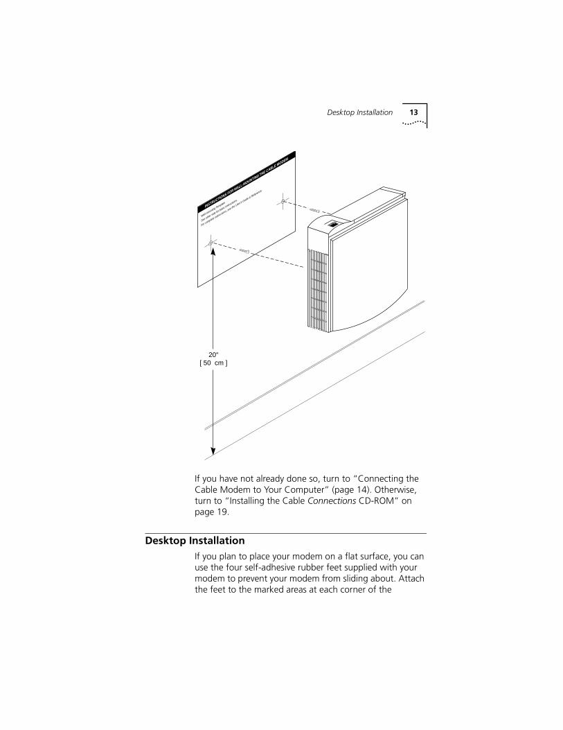
1 Remove the mounting template from the back of this guide.
2 Place the mounting template against the wall at the location chosen for the cable modem. The template should be parallel to and at least 50 cm from the floor. Insert drawing pins through the template cross hairs into the wall to mark the locations for the screws.
3 Secure the mounting screws into the wall. Do not drive the screws flush to the wall. The screw heads should be at least 6 mm away from the wall so it can lock into the slots on the modem’s case.
4 Fit the slots over the screw heads and let the modem slide down into position.
mountingholes
®
Desktop Installation 13
If you have not already done so, turn to “Connecting the Cable Modem to Your Computer” (page 14). Otherwise, turn to “Installing the Cable Connections CD-ROM” on page 19.
Desktop Installation If you plan to place your modem on a flat surface, you can use the four self-adhesive rubber feet supplied with your modem to prevent your modem from sliding about. Attach the feet to the marked areas at each corner of the
20"[ 50 cm ]
INSTRUCTIONS FOR WALL-MOUNTING THE CABLE MODEM
Wall-mounting Template
See other side for basic instructions.
For complete instructions, see the User's Guide & Reference.
®
14 CHAPTER 2: HARDWARE AND SOFTWARE INSTALLATION
underside of your modem. Turn to “Connecting the Cable Modem to Your Computer” (this page).
OfficeConnect Stacking Installation If you already own 3Com OfficeConnect products, you can use the four stacking clips supplied with those products to neatly and securely stack your cable modem with the other OfficeConnect unit(s). Refer to the other OfficeConnect products’ documentation for more information.
Connecting the Cable Modem to Your Computer TIP: Before you unplug any cords, label them or make a sketch of how they are connected. This can be helpful when you plug them back in later.
CAUTION: To avoid risk of electric shock, make sure your computer and all peripheral devices are turned off and unplugged from electrical sockets.
NOTE: Refer to the diagram on the following page while following these steps.
1 Leaving your computer turned on, make the following connections (use the following illustration as a guide):
■ Connect your cable line to the cable modem’s CATV cable connector. Be careful not to bend the wire in the center of the cable line when you connect it to the cable modem. After hand-tightening the CATV cable connector, use your adjustable wrench to firmly tighten it. Be careful not to over-tighten the connector or you may damage either the connector or your cable modem.
■ Plug the cable modem’s power supply into a wall socket or surge protector and into the cable modem’s power jack.
■ ETHERNET INSTALLATION: Plug one end of the RJ-45 network cable into the cable modem’s RJ-45 jack and the other end into the existing network interface card installed in your computer.

Installing the Cable ConnectionsTM CD-ROM 15
USB INSTALLATION: Plug the included USB cable into the cable modem’s USB port and into an available USB port on your computer. If your USB port is active, your PC will detect the cable modem within a few seconds. If you are using the Windows 98 operating system, it may prompt you for a driver disk. If so, insert the Cable Connections CD-ROM into your CD-ROM drive and point Windows to your CD-ROM drive’s letter when it asks you where to find the USB drivers for this device.
2 Verify that your cable modem starts up and initializes properly. You can tell that your modem is operating properly if the cable modem Power and Status LEDs are lit a solid green. If you are powering up your cable modem for the first time, allow 5 to 15 minutes for this process to complete. Consult the chapter titled “Cable Modem Operation” for a more in-depth description of the front panel LED indicators.
3 Plug the computer’s power cord back into the computer. Switch on the computer. When installation is complete, your setup should resemble the following diagram.
Installing the Cable ConnectionsTM CD-ROMAlthough you do not need to install the included Cable Connections CD-ROM to use your cable modem, you will want to discover the valuable free software products and Internet service provider offers included on the CD-ROM. To install the Cable Connections CD, follow the instructions inside the CD's jacket or on the CD-ROM itself.

16 CHAPTER 2: HARDWARE AND SOFTWARE INSTALLATION
-+
CATV
USB
10BT
12VDC
1.0A MAX
RESET
Model Name:CMX-S0-001/3C
Ethernet Address:CMX-S0-001/3C
S/N:3CPR1001
IIII III II IIII II II IIII II
IIII III II IIII II II IIII II
IIII III II IIII II II IIII II
OR

3 CABLE MODEM OPERATION
Once your cable modem is properly installed and the power supply is connected to AC power, it will automatically scan for the active cable modem channel from your cable company's server. Once the front panel LEDs indicate the modem is connected to the server, all you need to do is launch your Internet or e-mail software and you're ready to work online.
Interpreting the LEDs on the Front of Your Cable ModemHere's a quick overview of the LED lights on the front panel of your modem and what they can tell you about the performance of your modem and the condition of your connection.
1 Cable Modem Power - Indicates power is applied to the cable modem. This light is solid green when the modem is on.
2 Cable Modem Status - This LED varies in color (orange and green) and indicates the modem's status as described in the following table.
OfficeConnect Cable Modem
12
34 5

18 CHAPTER 3: CABLE MODEM OPERATION
:
3 Cable Activity - Indicates that data is being transmitted to or from your cable company over the RF (cable) port. Flashing orange indicates traffic.
4 PC Link Ethernet - Indicates that data is being transmitted to or from your PC over the Ethernet port. The LED is solid green when there is connection between the modem and an Ethernet port. If the LED is flashing green, there is traffic over the Ethernet port. If this LED is not lit, then there is no connection between the modem and an Ethenet port.
5 PC Link USB- Indicates that data is being transmitted to or from your PC over the USB port. The LED is solid green when there is connection between the modem and a USB port. If the LED is flashing green, there is traffic over the USB port. If this LED is not lit, then there is no connection between the modem and a USB port.
Connectors and Switches on the Back of Your Cable Modem
Table 1
LED STATE DESCRIPTION
BLINKING ORANGE Modem is searching for a downstream channel
SOLID ORANGE Downstream channel is locked
SOLID GREEN Registration complete and mdoem is operational
-+
CATV
USB
10BT
12VDC
1.0A M
AX
RESET
Model
Name:CMX
-S0-00
1/3C
Ethern
et Add
ress:C
MX-S0-
001/3C
S/N:3C
PR1001III
I III
II III
I II I
I IIII
II
IIII I
II II
IIII I
I II I
III II
IIII I
II II
IIII I
I II I
III II
cable RF connector
USB port
RJ-45 Ethernet port
power jack
reset button

Connectors and Switches on the Back of Your Cable Modem 19
Cable RF Connector: This is where you connect the coaxial cable that leads to your splitter or your cable wall jack.
USB Port: This is where you plug the included USB cable when performing a USB installation. The other end connects to an active USB port on your computer
RJ-45 Jack: This is where you plug the included RJ-45 Ethernet cable when performing an Ethernet installation. The other end connects to the RJ-45 jack on your network interface card (NIC) or active Ethernet port.
Power Jack: This is where you plug in the power adapter that came with your cable modem. Remember to use only the power supply that came with your cable modem.Reset Button: You can click this button when you are having trouble connecting to your Broadband Service Provider (BSP). This initiates a full reset of the modem and re-initiates the channel scan that occurs every time our modem is powered on. You can click the button by inserting a ballpoint pen into the hole and pressing until you feel the button click.

20 CHAPTER 3: CABLE MODEM OPERATION

4 TROUBLESHOOTING AND SUPPORT RESOURCES
Troubleshooting
I cannot access my e-mail or Internet service.■ Check all connections. Make sure the cable line is
securely connected to the cable jack on the back of the modem. Verify that the RJ-45 cable is securely plugged into both the modem and your network interface card, or, if you installed your cable modem via an active USB port, that the USB cable is securely fastened to the USB port on your computer and on the cable modem. Make sure your power supply is properly plugged into both the modem and a wall outlet or surge protector. If your cable modem is properly connected, the "Cable Modem Power", "Cable Modem Status", and "PC Link Status Ethernet/USB" (depending again on your type of installation) indicator lights on the front of the modem should all be a solid color.
■ Press the reset button on the back of your cable modem. You will need to use a fine-tipped instrument (such as the tip of a ball-point pen) to press the button. Push the button until you feel it click. Then try reconnecting to your Broadband Service Provider (BSP).
■ Call your Broadband Service Provider to verify that their service is two-way. This modem is designed for use with two-way cable plants.
■ If you installed via a network interface card, try to determine whether or not it is malfunctioning. Refer to its documentation for troubleshooting information. If you installed via an active USB port, verify that you have USB enabled on your system.
■ Make sure that TCP/IP is the default protocol in use by your system. See the section entitled "Configuring the TCP/IP Protocol" for more information.

22 CHAPTER 4: TROUBLESHOOTING AND SUPPORT RESOURCES
■ If you are using a cable line splitter so that you can connect the cable modem and a television at the same time, try removing the splitter and reconnecting your cables so that your cable modem is connected directly to your cable wall jack. Then try reconnecting to your Broadband Service Provider.
■ If you installed via a network interface card (NIC), try the following. Right-click the My Computer icon on your desktop. Then click Properties. Click the Device Manager tab and look for a yellow exclamation point or red X over your NIC in the "Network adapters" field. If you see either, you have an IRQ conflict. Click on your NIC card's description to highlight it and then click Remove. Then double-click Computer. A list of used IRQs appears. If all of the IRQs between 0 and 15 are in use, you will need to remove a device to free an IRQ for your NIC before you can reinstall it (by restarting your computer).
The Cable Status LED never stops blinking.
The signal from your cable company's equipment may be too weak or the cable line may not be properly attached to the modem. If the cable line is properly connected to the modem, call your cable company to verify whether or not a weak signal may be the problem.
All of LEDs on the front of my modem look right, but I still can't access the Internet.
■ If the “Cable Modem Power,” “Cable Modem Status,” and “PC Link Status” LEDs are on but not blinking, your cable modem is operating properly. Try shutting down and powering off your computer and then turning it back on. This will cause your computer to re-establish communications with your cable company's computer.
■ Press the reset button on the back of your cable modem. You will need to use a fine-tipped instrument (such as the tip of a ball-point pen) to press the button. Push the button until you feel it click. Then try reconnecting to your Broadband Service Provider (BSP).

Support Resources 23
■ You may not have installed TCP/IP properly or the TCP/IP parameters provided by your Broadband Service Provider may not be correct for your computer.
■ If you are using a cable line splitter so that you can connect the cable modem and a television at the same time, try removing the splitter and reconnecting your cables so that your cable modem is connected directly to your cable wall jack. Then try reconnecting to your BSP.
The power on my modem goes on and off sporadically. The Cable Modem Status light never stops blinking.
You may be using the wrong power supply. Check that the power supply you are using is the one that came with your cable modem.
Support Resources
Internet FTP Our FTP site provides a free library containing the same files as the BBS site. FTP to:
ftp://consumerftp.3com.com
World Wide WebTo visit our online support home page, log on to:
http://consumer.3com.com/cable/
You can send a message to technical support by clicking Contact Us in the “Site Tools” section of this Web site.
90-Day Free Installation Support3Com offers free installation support for this product for 90 days after purchase. Please call the following toll-free number.
888-877-5040After the 90-day period, refer to our regular technical support hotline option.

24 CHAPTER 4: TROUBLESHOOTING AND SUPPORT RESOURCES
Technical Support Hotline
Technical questions about 3Com cable modems can also be answered by technical support representatives. Regular long distance charges will apply if you are outside the 847 area code. The hours service is available are 8:00 am - 6:00 pm CST Monday through Friday and 9:00AM until 11:00PM CST Saturday through Sunday. Dial the following number:
847-262-2550
If You Are Still Having Problems■ Review this manual.
■ Call or visit your modem dealer. They may be able to assist you.
■ If your dealer can't help you, contact 3Com Technical Support. When you call, specify your modem's serial number (see beginning of chapter 2) and the software being used.
If You Need to Return the Modem to UsContact 3Com Customer Support. If the support representative determines that you need to return the modem, you will receive a USO (User Service Order) number. You must have a USO number before returning the modem to us. Ship the unit, postage paid, in a strong box made of corrugated cardboard with plenty of packing material. DO NOT send the modem back in the original box. Send ONLY the modem (NOT manuals, diskettes, etc.). Include your USO number, name, and address on the shipping label as well as inside the package. If possible, send the package via a courier capable of tracking the progress of the shipment. Ship to the following address:
3ComUSO #________
Dock 151800 W. Central Ave.
Mount Prospect, IL 60056
5 REGULATORY INFORMATION AND LIMITED WARRANTY
Manufacturer's Declaration of Conformity3Com3800 Golf RoadRolling Meadows, IL 60008U.S.A.
declares that the product 3Com OfficeConnect Cable Modem External conforms to the FCC's specifications:
Part 15
Operation is subject to the following two conditions:
(1) this device may not cause harmful electromagnetic interference, and
(2) this device must accept any interference received including interference that may cause undesired operations.
FCC Class B Statement
This device complies with Part 15 of the FCC Rules. Operation is subject to the following two conditions:
1 this device may not cause harmful electromagnetic interference, and
2 this device must accept any interference received including interference that may cause undesired operations.
FCC Notice: Radio and Television Interference
This equipment has been tested and found to comply with the limits for a Class B digital device, pursuant to Part 15 of the FCC Rules. These limits are designed to provide reasonable protection against harmful interference in a residential installation. This equipment generates, uses and can radiate radio frequency energy and, if not installed and

26 CHAPTER 5: REGULATORY INFORMATION AND LIMITED WARRANTY
used in accordance with the instructions, may cause harmful interference to radio communications. However, there is no guarantee that interference will not occur in a particular installation. If this equipment does cause harmful interference to radio or television reception, which can be determined by turning the equipment off and on, the user is encouraged to try to correct the interference by one or more of the following measures:
■ Reorient of relocate the receiving antenna.
■ Increase the separation between the equipment and receiver.
■ Connect the equipment into an outlet on a circuit different from that to which the receiver is connected.
■ Consult the dealer or an experienced radio/TV technician for help.
The user may find the following information prepared by the Federal Communications Commission helpful: The CIB Interference Handbook and The CIB Telephone Interference Bulletin.
These documents are available on the Internet through the FCC Compliance and Interference Bureau Home Page at http://www.fcc.gov/cib (listed under documents). Select CIB Interference Handbook or CIB Telephone Interference Bulletin.
Caution to the User
The user is cautioned that any changes or modifications not expressly approved by the party responsible for compliance could void the user's authority to operate the equipment.
Performance Specifications
This equipment has a bit-error rate (BER) less than 10-8 when the signal-to-noise ratio (SNR) is 23.5 dB or greater when operating in 64 QAM mode, and when the SNR is 30.0 dB or greater when operating in 256 QAM mode.
Export Notices■ Unlawful to export from the US or Canada without an
approved US Department of Commerce export license.

Manufacturer's Declaration of Conformity 27
■ The hardware contained in this product contains encryption software which may not be exported or transferred from the US or Canada without an approved US Department of Commerce export license.
License Agreement
You agree that you will not export or re-export the Software or accompanying documentation (or any copies thereof) or any products utilizing the Software or such documentation in violation of any applicable laws or regulations of the United States or the country in which you obtained them.
The software covered by this agreement may contain strong data encryption code that cannot be exported outside of the U.S. or Canada. You agree that you will not export/re-export, either physically or electronically, the encryption software or accompanying documentation (or copies thereof) or any products utilizing the encryption software or such documentation without obtaining written authorization from the U.S. Department of Commerce.
Industry Canada (IC)
This digital apparatus does not exceed the Class B limits for radio noise emissions from digital apparatus set out in the interference-causing equipment standard entitled Digital Apparatus, ICES-003 of Industry Canada.
Cet appareil numérique respecte les limites de bruits radioélectriques applicables aux appareils numériques de Classe B préscrites dans la norme sur le matèriel brouilleur: Appareils Numériques, NMB-003 édictée par l'Industrie Canada.
UL Listing/CUL Listing
This Information Technology Equipment (ITE) is UL-Listed and CUL-Listed for use with UL-Listed Personal Computers.

28 CHAPTER 5: REGULATORY INFORMATION AND LIMITED WARRANTY
Radio and Television Interference
This equipment generates and uses radio frequency energy and if not installed and used properly, in strict accordance with the manufacturer's instructions, may cause interference to radio and television reception. This device has been tested and found to comply with the limits for a Class B computing device in accordance with the specifications in Part 15 of FCC rules, which are designed to provide reasonable protection against such interference in a residential installation.
However, there is no guarantee that interference will not occur in a particular installation. If this device does cause interference to radio or television reception, which you can determine by monitoring reception when the modem is installed and when it is removed from the computer, try to correct the problem with one or more of the following measures:
■ Reorient the receiving antenna (for televisions with antenna reception only) or cable input device.
■ Relocate the computer with respect to the receiver.
■ Relocate the computer and/or the receiver so that they are on separate branch circuits.
If necessary, consult your dealer or an experienced radio/television technician for additional suggestions. You may find the following booklet, prepared by the Federal Communications Commission, helpful:
How to Identify and Resolve Radio-TV InterferenceProblemsStock No. 004-000-0345-4U.S. Government Printing OfficeWashington, DC 20402
In accordance with Part 15 of the FCC rules, the user is cautioned that any changes or modifications to the equipment described in this manual that are not expressly approved by 3Com could void the user's authority to operate the equipment.

3Com Corporation Limited Warranty 29
VCCI Statement
3Com Corporation Limited Warranty
Hardware3Com warrants to the end user (“Customer”) that this hardware product will be free from defects in workmanship and materials, under normal use and service, for the following length of time from the date of purchase from 3Com or its authorized reseller:
5 Years
3Com’s sole obligation under this express warranty shall be, at 3Com’s option and expense, to repair the defective product or part, deliver to Customer an equivalent product or part to replace the defective item, or if neither of the two foregoing options is reasonably available, 3Com may, in its sole discretion, refund to Customer the purchase price paid for the defective product. All products that are replaced will become the property of 3Com. Replacement products may be new or reconditioned. 3Com warrants any replaced or repaired product or part for ninety (90) days from shipment, or the remainder of the initial warranty period, whichever is longer.
Software
3Com warrants to Customer that each software program licensed from it will perform in substantial conformance to its program specifications, for a period of ninety (90) days from the date of purchase from 3Com or its authorized reseller. 3Com warrants the media containing software against failure during the warranty period. No updates are provided. 3Com's sole obligation under this express warranty shall be, at 3Com's option and expense, to refund the purchase price paid by Customer for any defective software product, or to replace any defective media with
30 CHAPTER 5: REGULATORY INFORMATION AND LIMITED WARRANTY
software which substantially conforms to applicable 3Com published specifications. Customer assumes responsibility for the selection of the appropriate applications program and associated reference materials. 3Com makes no warranty or representation that its software products will meet Customer’s requirements or work in combination with any hardware or applications software products provided by third parties, that the operation of the software products will be uninterrupted or error free, or that all defects in the software products will be corrected. For any third party products listed in the 3Com software product documentation or specifications as being compatible, 3Com will make reasonable efforts to provide compatibility, except where the non-compatibility is caused by a "bug" or defect in the third party's product or from use of the software product not in accordance with 3Com’s published specifications or user manual.
THIS 3COM PRODUCT MAY INCLUDE OR BE BUNDLED WITH THIRD PARTY SOFTWARE, THE USE OF WHICH IS GOVERNED BY A SEPARATE END USER LICENSE AGREEMENT. THIS 3COM WARRANTY DOES NOT APPLY TO SUCH THIRD PARTY SOFTWARE. FOR THE APPLICABLE WARRANTY, PLEASE REFER TO THE END USER LICENSE AGREEMENT GOVERNING THE USE OF SUCH SOFTWARE.
Year 2000 Warranty
In addition to the Hardware Warranty stated above, 3Com warrants that each product sold or licensed to Customer on and after January 1, 1998 that is date sensitive will continue performing properly with regard to such date data on and after January 1, 2000, provided that all other products used by Customer in connection or combination with the 3Com product, including hardware, software, and firmware, accurately exchange date data with the 3Com product, with the exception of those products identified at 3Com's Web site,
http://www.3com.com/products/yr2000.html
as not meeting this standard. If it appears that any product that is stated to meet this standard does not perform properly with regard to such date data on and after January

3Com Corporation Limited Warranty 31
1, 2000, and Customer notifies 3Com before the later of April 1, 2000, or ninety (90) days after purchase of the product from 3Com or its authorized reseller, 3Com shall, at its option and expense, provide a software update which would effect the proper performance of such product, repair such product, deliver to Customer an equivalent product to replace such product, or if none of the foregoing is feasible, refund to Customer the purchase price paid for such product.
Any software update or replaced or repaired product will carry a Year 2000 Warranty for ninety (90) days after purchase or until April 1, 2000, whichever is later.
Obtaining Warranty Service
Customer must contact a 3Com Corporate Service Center or an Authorized 3Com Service Center within the applicable warranty period to obtain warranty service authorization. Dated proof of purchase from 3Com or its authorized reseller may be required. Products returned to 3Com's Corporate Service Center must be pre-authorized by 3Com with a User Service Order (USO) number marked on the outside of the package, and sent prepaid and packaged appropriately for safe shipment, and it is recommended that they be insured or sent by a method that provides for tracking of the package. The repaired or replaced item will be shipped to Customer, at 3Com's expense, not later than thirty (30) days after 3Com receives the defective product.
WARRANTIES EXCLUSIVE
IF A 3COM PRODUCT DOES NOT OPERATE AS WARRANTED ABOVE, CUSTOMER'S SOLE REMEDY FOR BREACH OF THAT WARRANTY SHALL BE REPAIR, REPLACEMENT, OR REFUND OF THE PURCHASE PRICE PAID, AT 3COM'S OPTION. TO THE FULL EXTENT ALLOWED BY LAW, THE FOREGOING WARRANTIES AND REMEDIES ARE EXCLUSIVE AND ARE IN LIEU OF ALL OTHER WARRANTIES, TERMS, OR CONDITIONS, EXPRESS OR IMPLIED, EITHER IN FACT OR BY OPERATION OF LAW, STATUTORY OR OTHERWISE, INCLUDING WARRANTIES, TERMS, OR CONDITIONS OF MERCHANTABILITY, FITNESS

32 CHAPTER 5: REGULATORY INFORMATION AND LIMITED WARRANTY
FOR A PARTICULAR PURPOSE, SATISFACTORY QUALITY, CORRESPONDENCE WITH DESCRIPTION, AND NON-INFRINGEMENT, ALL OF WHICH ARE EXPRESSLY DISCLAIMED. 3COM NEITHER ASSUMES NOR AUTHORIZES ANY OTHER PERSON TO ASSUME FOR IT ANY OTHER LIABILITY IN CONNECTION WITH THE SALE, INSTALLATION, MAINTENANCE OR USE OF ITS PRODUCTS.
3COM SHALL NOT BE LIABLE UNDER THIS WARRANTY IF ITS TESTING AND EXAMINATION DISCLOSE THAT THE ALLEGED DEFECT OR MALFUNCTION IN THE PRODUCT DOES NOT EXIST OR WAS CAUSED BY CUSTOMER'S OR ANY THIRD PERSON'S MISUSE, NEGLECT, IMPROPER INSTALLATION OR TESTING, UNAUTHORIZED ATTEMPTS TO OPEN, REPAIR OR MODIFY THE PRODUCT, OR ANY OTHER CAUSE BEYOND THE RANGE OF THE INTENDED USE, OR BY ACCIDENT, FIRE, LIGHTNING, OTHER HAZARDS, OR ACTS OF GOD.
LIMITATION OF LIABILITY
TO THE FULL EXTENT ALLOWED BY LAW, 3COM ALSO EXCLUDES FOR ITSELF AND ITS SUPPLIERS ANY LIABILITY, WHETHER BASED IN CONTRACT OR TORT (INCLUDING NEGLIGENCE), FOR INCIDENTAL, CONSEQUENTIAL, INDIRECT, SPECIAL, OR PUNITIVE DAMAGES OF ANY KIND, OR FOR LOSS OF REVENUE OR PROFITS, LOSS OF BUSINESS, LOSS OF INFORMATION OR DATA, OR OTHER FINANCIAL LOSS ARISING OUT OF OR IN CONNECTION WITH THE SALE, INSTALLATION, MAINTENANCE, USE, PERFORMANCE, FAILURE, OR INTERRUPTION OF ITS PRODUCTS, EVEN IF 3COM OR ITS AUTHORIZED RESELLER HAS BEEN ADVISED OF THE POSSIBILITY OF SUCH DAMAGES, AND LIMITS ITS LIABILITY TO REPAIR, REPLACEMENT, OR REFUND OF THE PURCHASE PRICE PAID, AT 3COM'S OPTION. THIS DISCLAIMER OF LIABILITY FOR DAMAGES WILL NOT BE AFFECTED IF ANY REMEDY PROVIDED HEREIN SHALL FAIL OF ITS ESSENTIAL PURPOSE.
Disclaimer
Some countries, states, or provinces do not allow the exclusion or limitation of implied warranties or the limitation of incidental or consequential damages for
3Com Corporation Limited Warranty 33
certain products supplied to consumers, or the limitation of liability for personal injury, so the above limitations and exclusions may be limited in their application to you. When the implied warranties are not allowed to be excluded in their entirety, they will be limited to the duration of the applicable written warranty. This warranty gives you specific legal rights which may vary depending on local law.
Governing Law
This Limited Warranty shall be governed by the laws of the State of California, U.S.A. excluding its conflicts of laws principles and excluding the United Nations Convention on Contracts for the International Sale of Goods.

34 CHAPTER 5: REGULATORY INFORMATION AND LIMITED WARRANTY

6 WALL-MOUNTING TEMPLATE
3Com
Offi
ceC
onne
ct C
able
Mod
em E
xter
nal W
all-m
ount
ing
Tem
plat
e
For
com
plet
e in
stru
ctio
ns, s
ee th
e G
ettin
g S
tart
ed G
uide
.

36 CHAPTER 6: WALL-MOUNTING TEMPLATE