october 2016 alternative implicit mpm formulations · material point methods for geohazards 17th...
TRANSCRIPT
ALTERNATIVE IMPLICIT MPM FORMULATIONS
Antonia Larese, Ilaria Iaconeta, Riccardo Rossi, Eugenio Oñate
Material Point Methods for Geohazards 17th October 2016
GEO-RAMP H2020 MSCA-RISE-2014 GA n.645665

OUTLINE
• MOTIVATION • IMPLICIT vs EXPLICIT FORMULATIONS • IMPLICIT MPM
• GRID BASED • MESHLESS
• VALIDATION • KRATOS open-source platform • FUTURE WORK
2
Material Point Methods for Geohazards 17th October 2016
MOTIVATION
CIMNE tasks (ongoing doctoral work of I. Iaconeta) Development of a NUMERICAL TOOL
for the simulation of granular flows at the MACROSCALE, focusing on DRY GRANULAR MATERIAL in STATIC and FLOWING regime
3
Material Point Methods for Geohazards 17th October 2016
Training in Multiscale Analysis of multi-Phase Particulate Processes FP7 PEOPLE 2013 ITN–Grant Agreement nº607453
www.t-mappp.eu
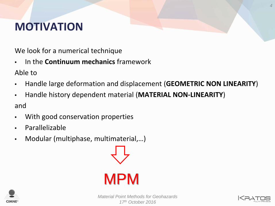
MOTIVATION
We look for a numerical technique • In the Continuum mechanics framework Able to • Handle large deformation and displacement (GEOMETRIC NON LINEARITY) • Handle history dependent material (MATERIAL NON-LINEARITY) and • With good conservation properties • Parallelizable • Modular (multiphase, multimaterial,…)
4
Material Point Methods for Geohazards 17th October 2016
MPM
IMPLICIT vs EXPLICIT FORMULATIONS
Most of MPM codes are explicit Few authors developed implicit MPM codes • Guilkey and Weiss – similarities FEM-MPM • Cummins and Brackbill – Newton-Krylov approach • Beuth – quasi static problems, higher order elements • Sanchez – quasi static problems • …
5
Material Point Methods for Geohazards 17th October 2016

IMPLICIT vs EXPLICIT FORMULATIONS
6
Material Point Methods for Geohazards 17th October 2016
IMPLICIT SCHEMES: • More complicated
• More expensive
More accurate
Stability does not depend on the wave propagation speed in the
media
Can solve from Static and Quasi static to dynamic and gravity
driven problems
More robust
More “FEM like”
IMPLICIT MPM
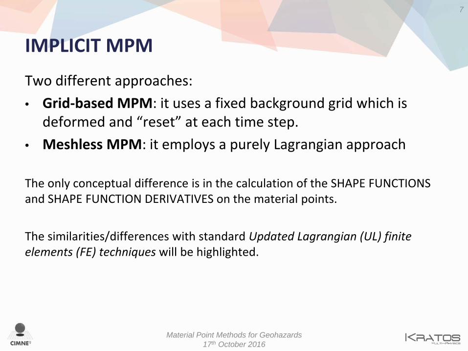
Two different approaches: • Grid-based MPM: it uses a fixed background grid which is
deformed and “reset” at each time step. • Meshless MPM: it employs a purely Lagrangian approach The only conceptual difference is in the calculation of the SHAPE FUNCTIONS and SHAPE FUNCTION DERIVATIVES on the material points. The similarities/differences with standard Updated Lagrangian (UL) finite elements (FE) techniques will be highlighted.
7
Material Point Methods for Geohazards 17th October 2016

GRID-BASED MPM

IMPLICIT MPM: GRID-BASED
9
Material Point Methods for Geohazards 17th October 2016
NOMENCLATURE: • i, j, k material points (MP) • I, J, K grid nodes (nodes)
Background grid: Linear Triangular elements • Unstructured grid • Easier definition of non regular
boundaries • Less accurate than quadrilateral
elements especially on the boundaries
Initial position of the MP: integration points of the FE background grid • Original mass transferred to the
MP with minimal error

IMPLICIT MPM: GRID-BASED
10
Material Point Methods for Geohazards 17th October 2016
Each MATERIAL POINT is defined by the material point itself and its connectivity It can be seen as a finite element with a moving integration point
Material Point i: • pi(xi, yi) • Connectivity IJK
Material Point j: • pj(xj, yj) • Connectivity IJK
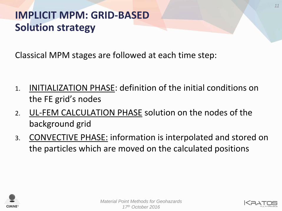
IMPLICIT MPM: GRID-BASED Solution strategy Classical MPM stages are followed at each time step:
1. INITIALIZATION PHASE: definition of the initial conditions on the FE grid’s nodes
2. UL-FEM CALCULATION PHASE solution on the nodes of the background grid
3. CONVECTIVE PHASE: information is interpolated and stored on the particles which are moved on the calculated positions
11
Material Point Methods for Geohazards 17th October 2016
1. Initialization phase
12
Material Point Methods for Geohazards 17th October 2016
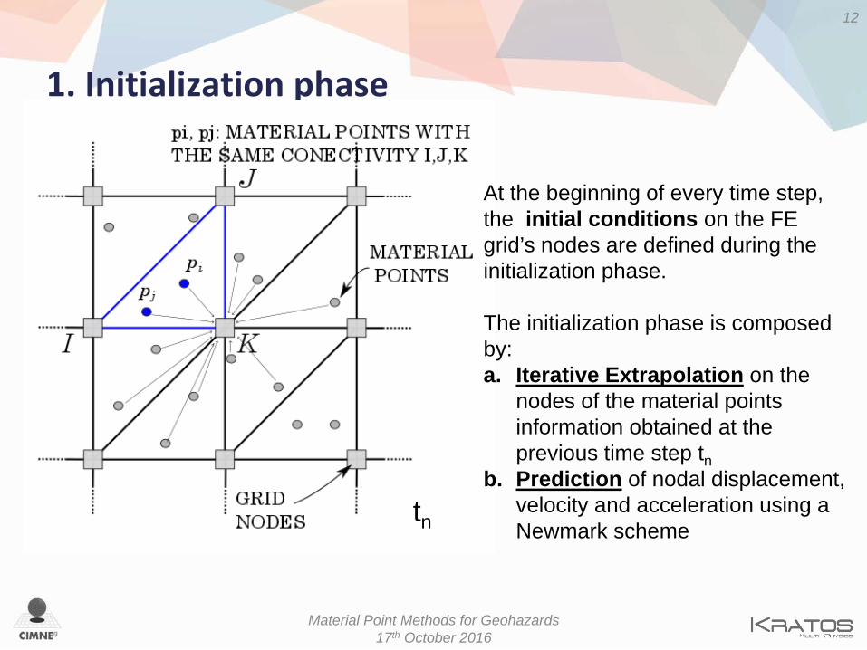
At the beginning of every time step, the initial conditions on the FE grid’s nodes are defined during the initialization phase. The initialization phase is composed by: a. Iterative Extrapolation on the
nodes of the material points information obtained at the previous time step tn
b. Prediction of nodal displacement, velocity and acceleration using a Newmark scheme
tn

Remark: nomenclature
13
Material Point Methods for Geohazards 17th October 2016
: MP displacement
: MP velocity
: MP acceleration
: superscript n or n+1 indicates the time step (tn or tn+1) on which the variable is evaluated. tn is the current (known) time step tn, while tn+1 is the next unknown time step
: subscript p refers to MP variables, while I to nodal one
: superscript it or k refer to the iteration within the iterative extrapolation and the time step respectively

1. Initialization phase a) Iterative extrapolation
14
Material Point Methods for Geohazards 17th October 2016
: known : identically null after grid reset
While
Loop over MP • Interpolation from nodes to MP ( )
: unkown

While
Loop over MP • Interpolation from nodes to MP ( , ) • Extrapolation from MP to nodes ( , , )
1. Initialization phase a) Iterative extrapolation
15
Material Point Methods for Geohazards 17th October 2016
: known : identically null after grid reset : unkown
Nodal momentum :
Nodal inertia :
Nodal mass :

1. Initialization phase a) Iterative extrapolation
16
Material Point Methods for Geohazards 17th October 2016
: known : identically null after grid reset : unkown
While
Loop over MP • Interpolation from nodes to MP ( , ) • Extrapolation from MP to nodes ( ) • Evaluation and Update of nodal

1. Initialization phase a) Iterative extrapolation
Once
17
Material Point Methods for Geohazards 17th October 2016
=
=
= identically zero
To be used in the Newmark prediction
Result of the iterative extrapolation
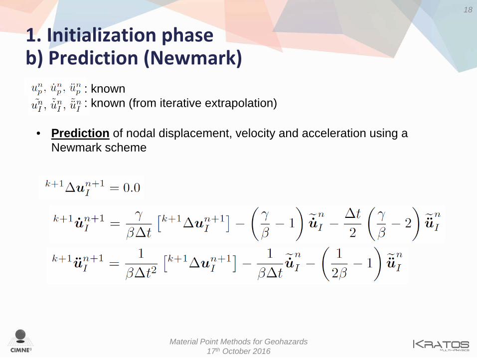
1. Initialization phase b) Prediction (Newmark)
18
Material Point Methods for Geohazards 17th October 2016
• Prediction of nodal displacement, velocity and acceleration using a Newmark scheme
: known : known (from iterative extrapolation)
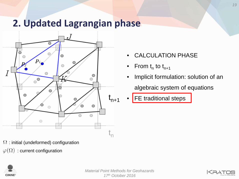
2. Updated Lagrangian phase
19
Material Point Methods for Geohazards 17th October 2016
: current configuration
: initial (undeformed) configuration
tn
• CALCULATION PHASE
• From tn to tn+1
• Implicit formulation: solution of an
algebraic system of equations
• FE traditional steps
tn+1

2. Updated Lagrangian phase
20
Material Point Methods for Geohazards 17th October 2016
FE PROCEDURE: a. ELEMENTAL SYSTEM.
The local left-hand-side (lhs) and right-handside (rhs) are evaluated in the current configuration
b. ASSEMBLING. The global LHS and RHS are obtained by assembling the local contributions
c. SOLVING. The system is iteratively solved. is calculated
• During the iterative procedure the nodes are allowed to move, accordingly to the nodal solution
• The material points do not change their local position within the geometrical element until the solution has reached convergence
: current configuration
: initial (undeformed) configuration
tn
tn+1
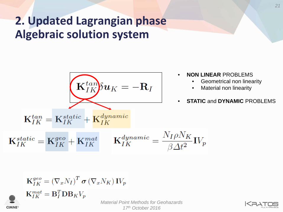
2. Updated Lagrangian phase Algebraic solution system
21
Material Point Methods for Geohazards 17th October 2016
• NON LINEAR PROBLEMS • Geometrical non linearity • Material non linearity
• STATIC and DYNAMIC PROBLEMS
FE PROCEDURE: a. ELEMENTAL SYSTEM. b. ASSEMBLING. c. SOLVING.
The system is iteratively solved is calculated
d. CHECK CONVERGENCE • NEWMARK CORRECTION
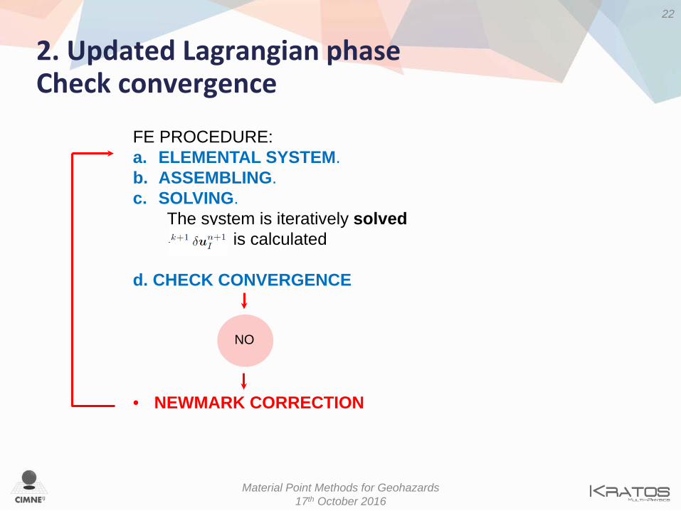
2. Updated Lagrangian phase Check convergence
22
Material Point Methods for Geohazards 17th October 2016
NO
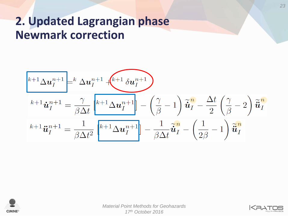
2. Updated Lagrangian phase Newmark correction
23
Material Point Methods for Geohazards 17th October 2016

FE PROCEDURE: a. ELEMENTAL SYSTEM. b. ASSEMBLING. c. SOLVING.
The system is iteratively solved is calculated
d. CHECK CONVERGENCE • NEWMARK CORRECTION
2. Updated Lagrangian phase Check convergence
24
Material Point Methods for Geohazards 17th October 2016
NO YES
END Go to next step:
Convective Phase

3. Convective phase
25
Material Point Methods for Geohazards 17th October 2016
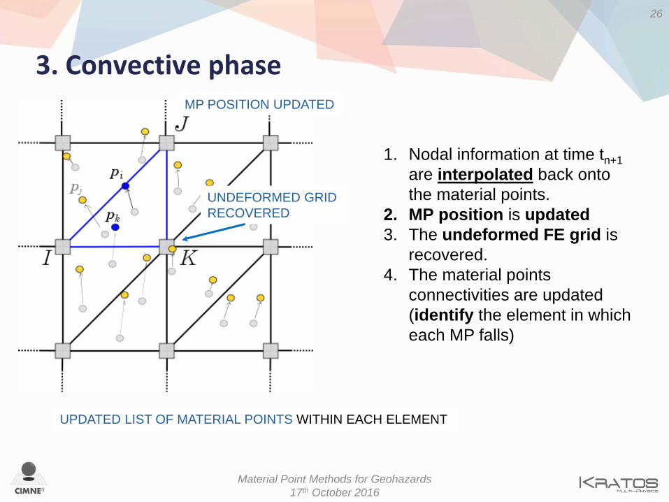
1. Nodal information at time tn+1 are interpolated back onto the material points.
MP displacement:
MP velocity:
MP acceleration:
MP position (update):
2. MP position is updated
3. Convective phase
26
Material Point Methods for Geohazards 17th October 2016
1. Nodal information at time tn+1 are interpolated back onto the material points.
2. MP position is updated 3. The undeformed FE grid is
recovered. 4. The material points
connectivities are updated (identify the element in which each MP falls)
UPDATED LIST OF MATERIAL POINTS WITHIN EACH ELEMENT
UNDEFORMED GRID RECOVERED
MP POSITION UPDATED
MESHLESS MPM

IMPLICIT MPM: MESHLESS
28
Material Point Methods for Geohazards 17th October 2016
• The Lagrangian nodes are moving during the process
• They are used for the computation of the shape functions in a meshless fashion
• No mesh, no connectivity is present
• Nodes will carry their history
• No need of extrapolating information from MP to the nodes

IMPLICIT MPM: MESHLESS How to compute the MP shape functions?
29
Material Point Methods for Geohazards 17th October 2016
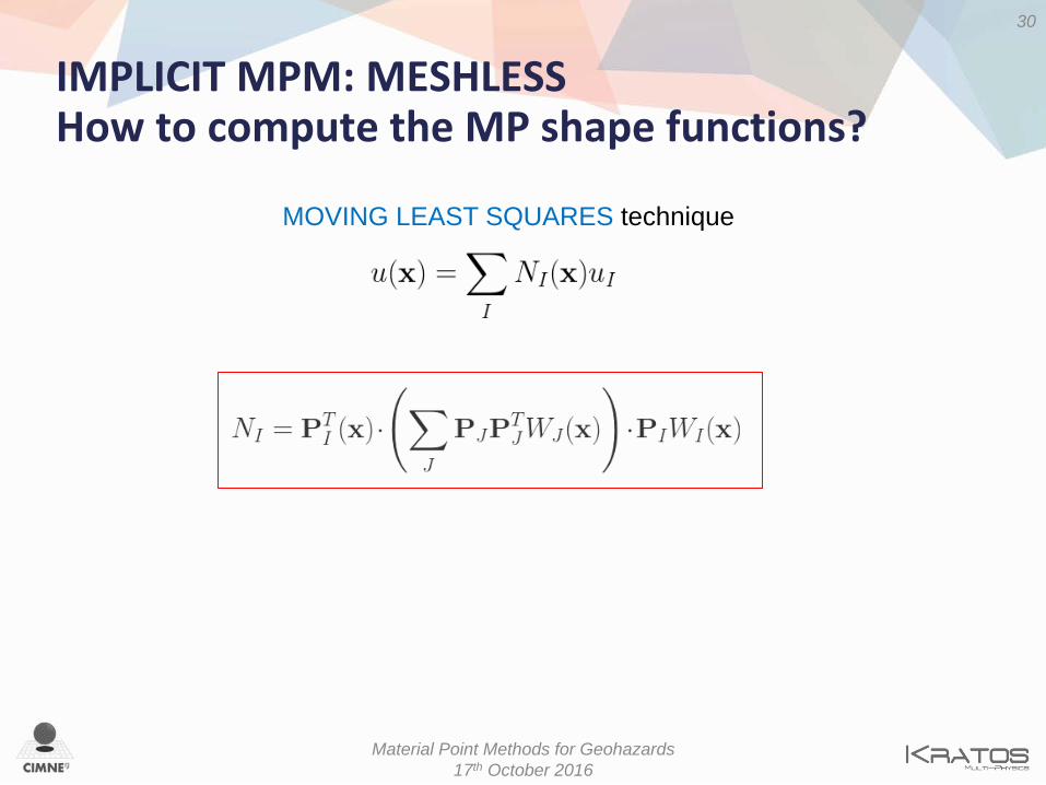
MOVING LEAST SQUARES technique to approximate a given function u(x) using polynomial functions of the type
unknown coefficients
Nodal value of the function uI = u(xI)
IMPLICIT MPM: MESHLESS How to compute the MP shape functions?
30
Material Point Methods for Geohazards 17th October 2016
MOVING LEAST SQUARES technique

IMPLICIT MPM: MESHLESS
31
Material Point Methods for Geohazards 17th October 2016
MLS shape functions: • Comply the PARTITION OF UNITY property at the material points positions: • Do NOT comply the DELTA KRONECKER property at the nodes
• Are NOT INTERPOLANTS

IMPLICIT MPM: MESHLESS
The MLS shape functions do NOT comply the DELTA KRONECKER property at the nodes
Problem on the imposition of Dirichlet boundary conditions
These should be treated using a MULTIPOINT CONSTRAINT technique. We choose Lagrangian Multipliers
(check http://www.colorado.edu/engineering/CAS/courses.d/IFEM.d/IFEM.Ch08.d/IFEM.Ch08.pdf and http://www.colorado.edu/engineering/CAS/courses.d/IFEM.d/IFEM.Ch09.d/IFEM.Ch09.pdf )
32
Material Point Methods for Geohazards 17th October 2016
IMPLICIT MPM: MESHLESS
33
Material Point Methods for Geohazards 17th October 2016
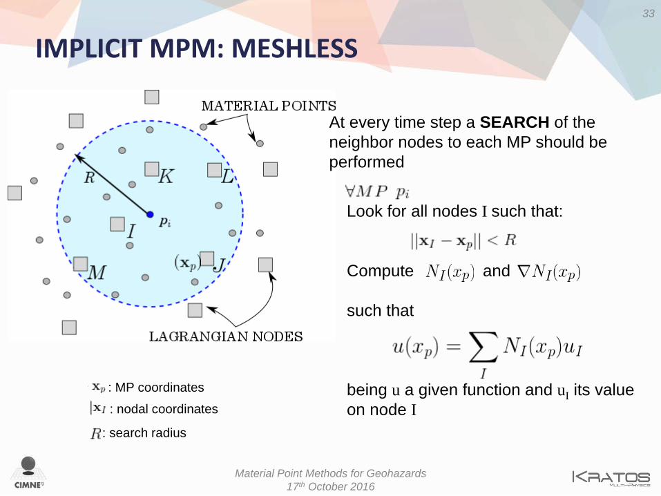
Look for all nodes I such that: Compute and such that being u a given function and uI its value on node I
: search radius
: MP coordinates
: nodal coordinates
At every time step a SEARCH of the neighbor nodes to each MP should be performed

IMPLICIT MPM: MESHLESS Solution strategy
1. INITIALIZATION PHASE • NO extrapolation from particle (the nodes keep their history) • Newmark prediction
identical to Grid based MPM but
Prediction made on the nodes
34
Material Point Methods for Geohazards 17th October 2016
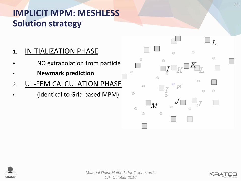
IMPLICIT MPM: MESHLESS Solution strategy
1. INITIALIZATION PHASE • NO extrapolation from particle • Newmark prediction
2. UL-FEM CALCULATION PHASE • (identical to Grid based MPM)
35
Material Point Methods for Geohazards 17th October 2016

IMPLICIT MPM: MESHLESS Solution strategy
1. INITIALIZATION PHASE • NO extrapolation from particle • Newmark prediction
2. UL-FEM CALCULATION PHASE • (identical to Grid based MPM)
3. CONVECTIVE PHASE • Update MP position interpolating nodal information
36
Material Point Methods for Geohazards 17th October 2016
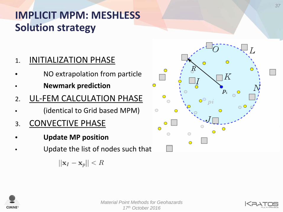
IMPLICIT MPM: MESHLESS Solution strategy
1. INITIALIZATION PHASE • NO extrapolation from particle • Newmark prediction
2. UL-FEM CALCULATION PHASE • (identical to Grid based MPM)
3. CONVECTIVE PHASE • Update MP position • Update the list of nodes such that
37
Material Point Methods for Geohazards 17th October 2016

CONSTITUTIVE LAWS

• HYPERELASTIC LAW: NEO-HOOKEAN MATERIAL
Ψ 𝐽𝐽,𝑪𝑪𝒆𝒆 =12𝐾𝐾𝑙𝑙𝑙𝑙2 𝐽𝐽 +
12𝜇𝜇 𝑡𝑡𝑡𝑡 𝑪𝑪𝒆𝒆 − 3
𝑺𝑺 = 2𝜕𝜕Ψ𝜕𝜕𝑪𝑪𝒆𝒆
𝑪𝑪𝒆𝒆 ℂ = 4𝜕𝜕2Ψ
𝜕𝜕𝑪𝑪𝒆𝒆𝜕𝜕𝑪𝑪𝒆𝒆
Ψ : Free energy function
S : II Piola-Kirchhoff stress tensor ℂ: IV order constitutive tensor
CONSTITUTIVE LAWS Elastic regime
• HYPOELASTIC LAW – future work

• HYPERELASTIC-PLASTICITY: J2 PLASTIC THEORY “Computational Inelasticity”, Simo & Hughes (1998)
𝑭𝑭 = 𝑭𝑭𝑒𝑒𝑭𝑭𝑝𝑝 𝑭𝑭 = 𝐽𝐽1/3𝑭𝑭�
𝝉𝝉 = 𝐾𝐾 𝑙𝑙𝑙𝑙𝐽𝐽 𝟏𝟏 +12𝐺𝐺 𝑑𝑑𝑑𝑑𝑑𝑑𝒃𝒃�𝑒𝑒
𝑑𝑑𝝉𝝉𝑛𝑛+1 = ℂ�𝑛𝑛+1: 𝑑𝑑𝜺𝜺𝑛𝑛+1 − 𝜺𝜺𝑛𝑛+1𝑝𝑝
Multiplicative decomposition of the total deformation gradient F
KIRCHHOFF STRESS TENSOR 𝝉𝝉
𝑭𝑭 : Total deformation gradient
𝑭𝑭�: Volume-preserving part of 𝑭𝑭
𝒃𝒃�𝑒𝑒: Elastic part of Left Cauchy-Green tensor
𝐾𝐾 : Bulk modulus 𝐺𝐺 : Shear modulus
CONSTITUTIVE LAWS Plastic regime
ELASTIC PLASTIC
Material Point Methods for Geohazards 17th October 2016
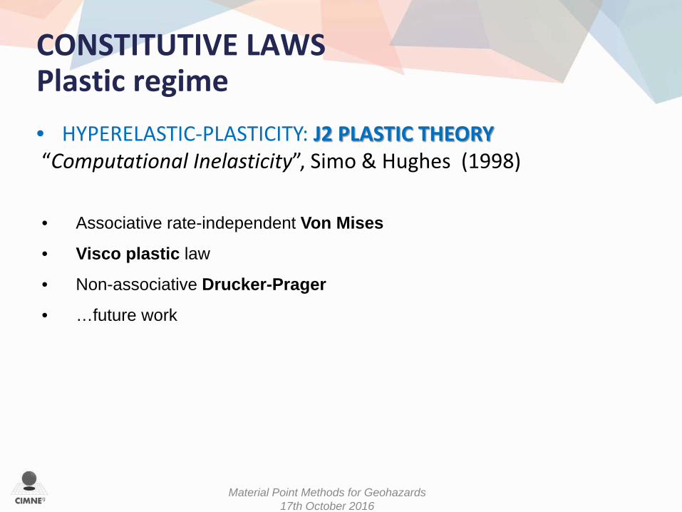
• HYPERELASTIC-PLASTICITY: J2 PLASTIC THEORY “Computational Inelasticity”, Simo & Hughes (1998)
CONSTITUTIVE LAWS Plastic regime
• Associative rate-independent Von Mises
• Visco plastic law
• Non-associative Drucker-Prager
• …future work
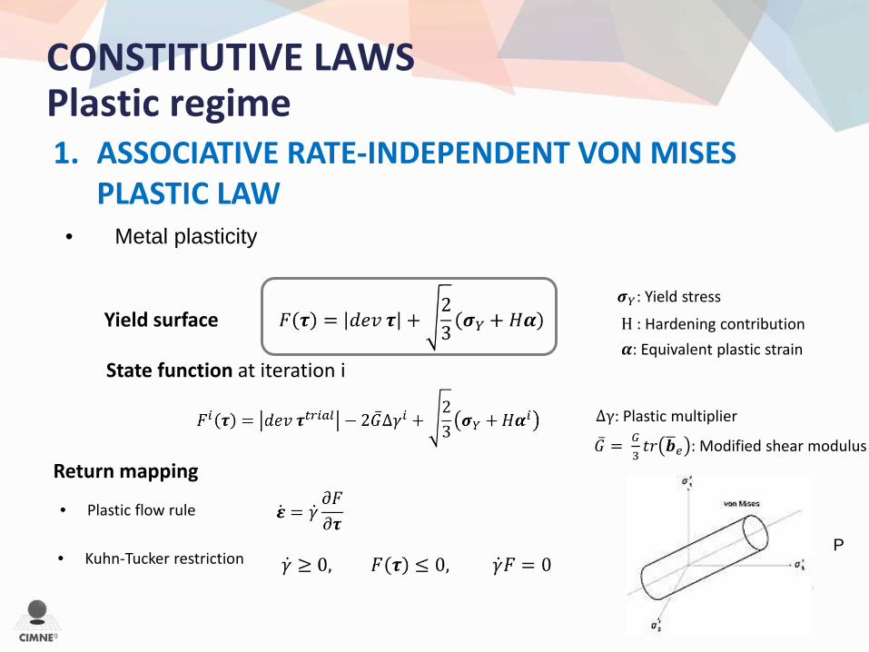
1. ASSOCIATIVE RATE-INDEPENDENT VON MISES PLASTIC LAW
Yield surface
• Kuhn-Tucker restriction
• Plastic flow rule
Return mapping
State function at iteration i
H : Hardening contribution
∆γ: Plastic multiplier
�̅�𝐺 = 𝐺𝐺3𝑡𝑡𝑡𝑡 𝒃𝒃�𝑒𝑒 : Modified shear modulus
𝝈𝝈𝑌𝑌: Yield stress
𝜶𝜶: Equivalent plastic strain
CONSTITUTIVE LAWS Plastic regime
P
• Metal plasticity

2. VISCO PLASTIC LAW Duvaut-Lions’ model
η: Viscosity Case of constant viscosity
CONSTITUTIVE LAWS Plastic regime
Yield surface
State function at iteration i
• NON NEWTONIAN plastics
• Plastic flow rule
Return mapping
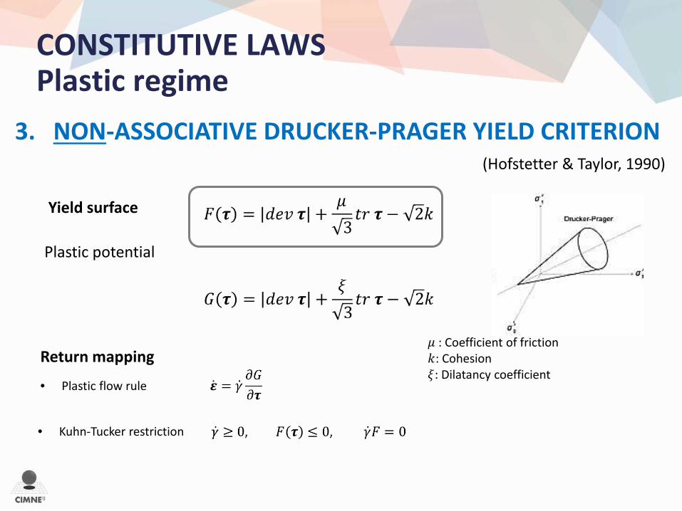
3. NON-ASSOCIATIVE DRUCKER-PRAGER YIELD CRITERION (Hofstetter & Taylor, 1990)
Plastic potential
𝜇𝜇 : Coefficient of friction 𝑘𝑘: Cohesion 𝜉𝜉: Dilatancy coefficient
CONSTITUTIVE LAWS Plastic regime
Yield surface
• Kuhn-Tucker restriction
• Plastic flow rule
Return mapping
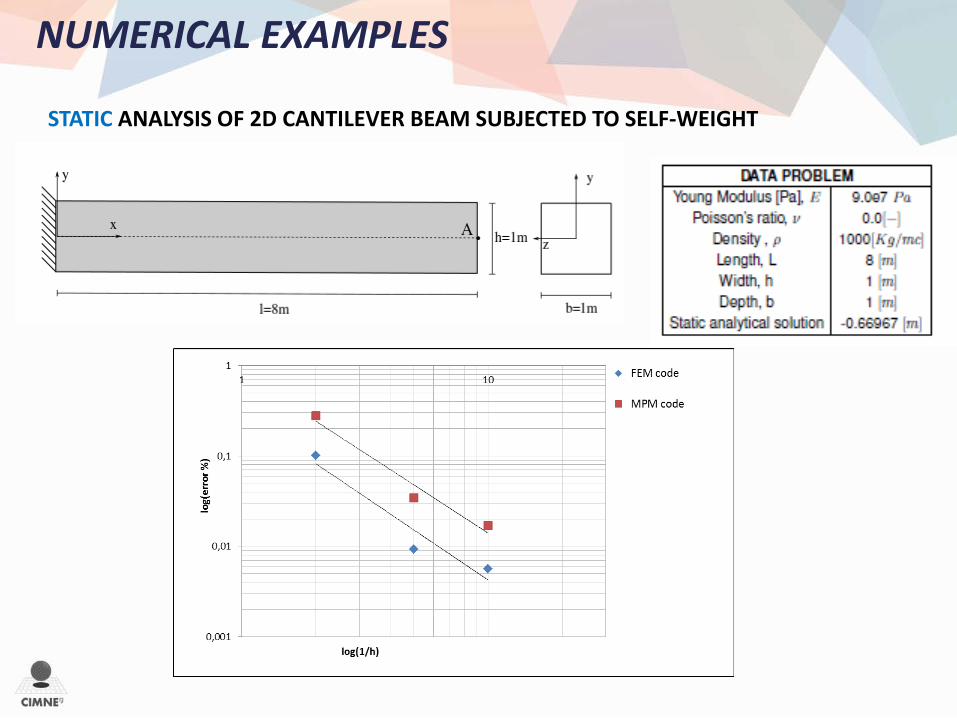
NUMERICAL EXAMPLES
STATIC ANALYSIS OF 2D CANTILEVER BEAM SUBJECTED TO SELF-WEIGHT
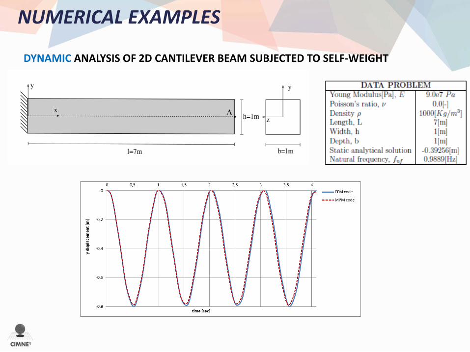
NUMERICAL EXAMPLES
DYNAMIC ANALYSIS OF 2D CANTILEVER BEAM SUBJECTED TO SELF-WEIGHT

NUMERICAL EXAMPLES
DYNAMIC ANALYSIS OF 2D CANTILEVER BEAM SUBJECTED TO SELF-WEIGHT
Displacement FEM CODE
MPM CODE

NUMERICAL EXAMPLES
DYNAMIC ANALYSIS OF 2D CANTILEVER BEAM SUBJECTED TO SELF-WEIGHT
Velocity along y-direction FEM CODE
MPM CODE

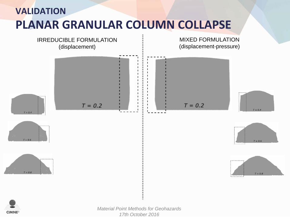
VALIDATION PLANAR GRANULAR COLUMN COLLAPSE
NON-ASSOCIATIVE DRUCKER-PRAGER YIELD CRITERION (Hofstetter & Taylor, 1990)
(Mast et al., 2015)
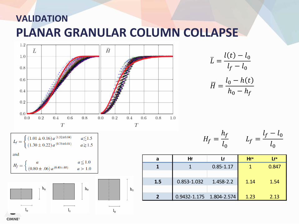
VALIDATION PLANAR GRANULAR COLUMN COLLAPSE
𝐿𝐿� =𝑙𝑙 𝑡𝑡 − 𝑙𝑙0𝑙𝑙𝑓𝑓 − 𝑙𝑙0
𝐻𝐻� =𝑙𝑙0 − ℎ 𝑡𝑡ℎ0 − ℎ𝑓𝑓
𝐻𝐻𝑓𝑓 =ℎ𝑓𝑓𝑙𝑙0
𝐿𝐿𝑓𝑓 =𝑙𝑙𝑓𝑓 − 𝑙𝑙0𝑙𝑙0
a Hf Lf Hf* Lf*
1 1 0.85-1.17 1 0.847
1.5 0.853-1.032 1.458-2.2 1.14 1.54
2 0.9432-1.175 1.804-2.574 1.23 2.13
Material Point Methods for Geohazards 17th October 2016
IRREDUCIBLE FORMULATION (displacement)
MIXED FORMULATION (displacement-pressure)
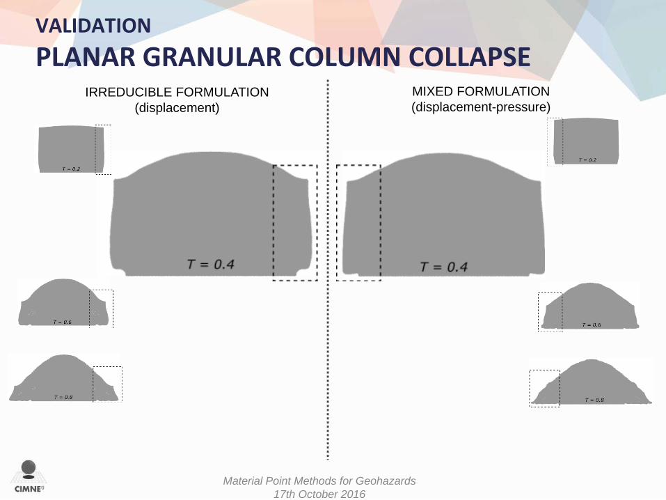
VALIDATION PLANAR GRANULAR COLUMN COLLAPSE
Material Point Methods for Geohazards 17th October 2016
IRREDUCIBLE FORMULATION (displacement)
MIXED FORMULATION (displacement-pressure)
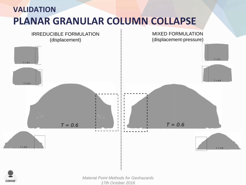
VALIDATION PLANAR GRANULAR COLUMN COLLAPSE
Material Point Methods for Geohazards 17th October 2016
IRREDUCIBLE FORMULATION (displacement)
MIXED FORMULATION (displacement-pressure)
VALIDATION PLANAR GRANULAR COLUMN COLLAPSE

Material Point Methods for Geohazards 17th October 2016
IRREDUCIBLE FORMULATION (displacement)
MIXED FORMULATION (displacement-pressure)
VALIDATION PLANAR GRANULAR COLUMN COLLAPSE

Arrangement of softer and stiffer photoelastic disks
PISTON 1: initial pre-compression on the disks
PISTON 2: sinusoidal impulse imposed at the bottom of the sample
VALIDATION PHOTOELASTIC DISKS
In collaboration with the MULTI SCALE MECHANICS group of the University of Twente (NL) MSc G. Oliveri, Prof. V. Magnanimo , Prof. S. Luding
PISTON 1
PISTON 2
OBJECTIVE: study of wave propagation in heterogeneous media
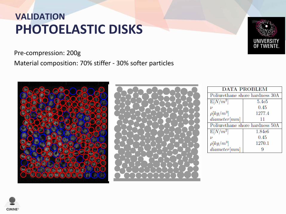
Pre-compression: 200g Material composition: 70% stiffer - 30% softer particles
VALIDATION PHOTOELASTIC DISKS

VALIDATION PHOTOELASTIC DISKS
EVOLUTION OF THE CHAIN OF STRESS
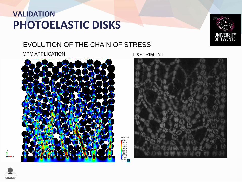
VALIDATION PHOTOELASTIC DISKS
EXPERIMENT MPM APPLICATION
EVOLUTION OF THE CHAIN OF STRESS
FUTURE WORK
• 3D • Constitutive laws (T-MAPPP) • Quadrilateral elements • Frictional boundary conditions
• Multi-phase
60
Material Point Methods for Geohazards 17th October 2016

61
Kratos is a framework for building multi-disciplinary (MULTI-PHYSICS) finite element programs. It provides several tools for fast implementation of finite element applications. CFD, CSD, Thermally Coupled Problems, Particles, ...
OPEN SOURCE
The dynamic nature of KRATOS itself is the principal reason of the continued evolution.
FLEXIBILITY
Kratos can be used with research purposes or by engineers looking for a solution to complex industrial problems
PARALLEL HPC
High performance computing in an OpenMP/MPI - based software.
www.cimne.com/kratos

62
∫dΩ Ind. R&D Test
KRATOS www.cimne.com/kratos
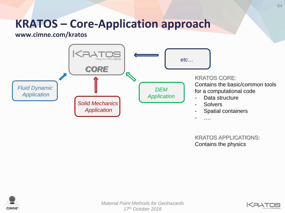
KRATOS – Core-Application approach www.cimne.com/kratos
64
Material Point Methods for Geohazards 17th October 2016
CORE KRATOS CORE: Contains the basic/common tools for a computational code - Data structure - Solvers - Spatial containers - ….
KRATOS APPLICATIONS: Contains the physics
Fluid Dynamic Application
Solid Mechanics Application
DEM Application
etc…

KRATOS – Core-Application approach www.cimne.com/kratos
65
Material Point Methods for Geohazards 17th October 2016
CORE
Fluid Dynamic Application
Solid Mechanics Application
DEM Application
Thermo-Mechanics Applications
Particle Mechanics Application (MPM)
FSI Application
COUPLED or DERIVED APPLICATION • High reusability • Flexibility • Reduced conflicts
etc…

Thank you!
Antonia Larese [email protected]
www.cimne.com/kratos Kratos FORUM: kratos-wiki.cimne.upc.edu/forum
REFERENCES: • Iaconeta, I., Guo, Z. Larese, A., Rossi, R., An implicit grid-based and a meshless
MPM formulation for problems in solid mechanics. Submitted to International Journal for Numerical Methods in Engineering (2016)
• Iaconeta, I., Larese, A., Rossi, R., Oñate, E., An implicit material point method applied to granular flows. Proceeding of the 1st International Conference on the Material Point Method, MPM 2017, Delft, Netherlands (2017)