ocean tv manual o37-o45 m-series - satellitetv4boats tv manual o37-o45 m-series low...
TRANSCRIPT

Ocean TV Ocean Series Antennas
OCEAN TV 1 www.oceantv.com.au
OCEAN TVSatellite Antennas
www.oceantv.com.au
Ocean Series O37M and O45MInstallation and User Manual
Version 1.34
© Ocean TV 2010
Ocean TV Ocean Series Antennas
OCEAN TV 2 www.oceantv.com.au
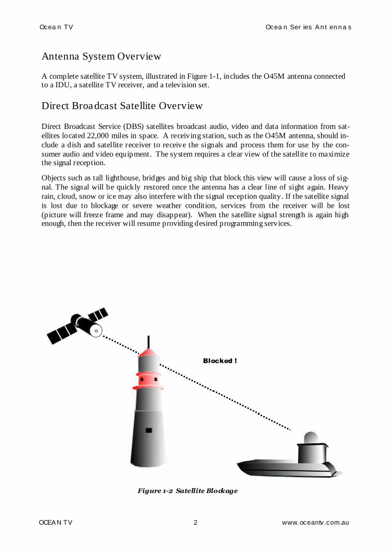
Blocked !
Figure 1-2 Satellite Blockage
Antenna System Overview
A complete satellite TV system, illustrated in Figure 1-1, includes the O45M antenna connectedto a IDU, a satellite TV receiver, and a television set.
Direct Broadcast Satellite Overview
Direct Broadcast Service (DBS) satellites broadcast audio, video and data information from sat-ellites located 22,000 miles in space. A receiving station, such as the O45M antenna, should in-clude a dish and satellite receiver to receive the signals and process them for use by the con-sumer audio and video equipment. The system requires a clear view of the satellite to maximizethe signal reception.
Objects such as tall lighthouse, bridges and big ship that block this view will cause a loss of sig-nal. The signal will be quickly restored once the antenna has a clear line of sight again. Heavyrain, cloud, snow or ice may also interfere with the signal reception quality. If the satellite signalis lost due to blockage or severe weather condition, services from the receiver will be lost(picture will freeze frame and may disappear). When the satellite signal strength is again highenough, then the receiver will resume providing desired programming services.

Ocean TV Ocean Series Antennas
OCEAN TV 3 www.oceantv.com.au
System Components
Antenna UnitThe antenna unit houses the antenna positioningmechanism, LNB (low noise block), and control ele-ments within a n enclosed weatherproof dome.
Weather tight connectors join the power, signal, andcontrol cabling from the below decks units.
IDU (InDoor Unit)The IDU is the system’s user interface, providingaccess to the system and its functions through anLCD and three buttons.
The IDU also serves as the vessel’s junction box,allowing the system to use vessel power, and supplyand receive data to/from the antenna unit.
Satellite ReceiverThe Satellite Receiver is a Set Top Box that allowsthe Satellite Signals to be displayed on theTelevision.
Satellite Receivers are supplied by the end user orunder contract by a Subscription Satellite TVProvider.
Figure 1 – 3 System Components

Ocean TV Ocean Series Antennas
OCEAN TV 4 www.oceantv.com.au
Antenna Type Parabola
Frequency Band Ku Band
Operating Frequency 10.7GHz to 12.75GHz
Dish Dimension 450mm
Radome Dimension 550x580mm
Antenna Weight 15kg
Antenna Gain 33dBi
Minimum EIRP 49-48dBW
Polarization V/H or RHCP/LHCP
Type of Stabilization 2-Axis Step Motor
Elevation Range 5° to 90°
Azimuth Range 400°
Tracking Rate 50°/sec
Temperate Range -20° to 70°
Power 12~24VDC (24w at 12vdc)
Auto Skew Range -90° to 90°
Ocean O45M
Antenna Type Parabola
Frequency Band Ku Band
Operating Frequency 10.7GHz to 12.75GHz
Dish Dimension 370mm
Radome Dimension 440x430mm
Antenna Weight 9kg
Antenna Gain 31dBi
Minimum EIRP 50dBW
Polarization V/H or RHCP/LHCP
Type of Stabilization 2-Axis Step Motor
Elevation Range 5° to 90°
Azimuth Range 400°
Tracking Rate 50°/sec
Temperate Range -20° to 70°
Power 12~24VDC (19w at 12vdc)
Ocean O37M

Ocean TV Ocean Series Antennas
OCEAN TV 5 www.oceantv.com.au
SD Satellite Receiver
Ocean TV System Overview
Setup 1
1 Television with SD Satellite Receiver
Antenna
12-24v DC
IDU Indoor Unit
Televisions
Coaxial ControlCable
NOTE:.
Further Installation Options are available in Appendix E
Antenna System Overview
Figure 1 –1 System Diagram

Ocean TV Ocean Series Antennas
OCEAN TV 6 www.oceantv.com.au
1 IntroductionSpecification………………….………………………………………………………………. 4Antenna System Overview……………………………………………………………….. 5Direct Broadcast Satellite Overview………………………….………………………. 6Sy stem Components……………………………………………………………………..… 7
2 InstallationUnpacking the Unit………………………………..……………………...................... 9Preparing for the installation…………………………………………………………. 10Selecting the location………….………………………………………………….……… 11Equipment and cable installation…………..…………………………………….…. 12Setting the LNB Skew Angle (Manual Skew version only)…………………. 13
3 OperationReceiving Satellite TV Signals…………….………………………………………….. 15Turning the System On/Off…………..………………..……………………………... 16Changing Channels………………………….…………………...…..……………….…. 17Watching TV…………………………………………………………..…………….…..…. 17Switching between Satellites……………………………………………….…………. 17Operating the IDU……………………………………….……………………………….. 18Choosing the Correct Satellite to Track……………………...……………….... 19
4 TroubleshootingSimple Check……………………………………………..………………….……………. 21Causes and Remedies……………………………….……..……………………...……. 22
i Appendix AHow to set the skew angle………………………………………………….....……. 23
ii Appendix BSatellite Cov erage Map…………………..…………………………..………..……. 26
iii Appendix CFirmware Upgrade…………………….……………………………………..…………. 27
iv Appendix DO37M Antenna Drawing..…………………….…..………...…………………..…. 31O45M Antenna Drawing..…………………….…..……………………………....…. 32
v Appendix ESy stem Diagrams..…………………….…..………...……………………..……..…. 33
vi Appendix FSatellite Coverage Maps……………….…..………...…………………….……..…. 40
5 AccessoriesInstallation and User Accessories…………………………………………………. 42
Contents

Ocean TV Ocean Series Antennas
OCEAN TV 7 www.oceantv.com.au
Notes, Cautions, and Warnings
Caution - Improper handling by unqualified personnel can cause seriousdamage to this equipment. Unqualified personnel who tamper with thisequipment may be held liable for any resultant damage to the equipment.
Install under DRY condition ONLY. Do not install this system in the rain, orunder wet conditions. Moisture may effect the electronics and v oid warranty.
Warning - Two people are needed to install the antennas onto the roof. Donot try to install the antenna by y ourself.
Note - Beforey ou begin, carefully read each of the procedures in this man-ual. If y ou have not performed similar operations on similar equipment, donot attempt to perform these procedures.
Welcome
Congratulations on purchasing the Ocean TV Marine Satellite Antenna System.
The Ocean Series O37M and O45M satellite antenna system is a innovative and technologicallyadvanced satellite In-Motion system. The O37M/O45M has a unique combination of state-of-theart components with the most sophisticated satellite acquisition and tracking programs to providethe following features:
■Fast satellite acquisition■Gyro and Signal Stabilised smooth tracking■Compatible with any Satellite Receiver■Compatible with all Direct Broadcast Satellites (DBS)■Built-in Digital Broadcast Receiver (DVB)■Capable of High Definition receiving■Multi Output as standard (Foxtel IQ and Austar MyStar Compatible)
Ocean TV Antennas have been designed to be simple to operate and provide years of trouble freeperformance.
Welcome to the Ocean TV family.
OCEAN TV

Ocean TV Ocean Series Antennas
OCEAN TV 8 www.oceantv.com.au
This section offers a general explanation of how properly to install the O37M and O45Mantenna. Installation of the O37M or O45M antenna must be accomplished by or under thesupervision of an authorized dealer for the Limited Warranty to be valid and in force. The stepsin the installation and setup process are as follows:
Unpacking the unit……………….……………………………………………….……………………. 9Preparing for the installation…………………………………………….…………………………. 10Selecting the location………….……………………………………….……………………………….. 11Equipment and cable installation…………..……………………………………………………… 12
Installation

Ocean TV Ocean Series Antennas
OCEAN TV 9 www.oceantv.com.au
Unpacking the unit
1. Open box and remove packing material.The following items are included in the packaging of the O37M and O45M antenna.
Item Description Quantity
1 O37M or O45M Antenna Unit 1 each
2 IDU (In Door Unit) 1 each
3 Power Cable 1 each
4 Coaxial Cable (10m) 1 each
5 Coaxial Cable (1m) 1 each
6 Installation & User Manual 1 set
7 Cable Right Hand Connectors (O37M Only) 1 Set of 6
Table 2-1 Parts included
2. Lift dome out of box vertically. Do not turn box and “roll” out, or turn upside down toremove.
Lift Unit straight upout of the carton!
Figure 2-1 Unpacking the unit
Note: Optional approved Cables and accessories are available from Ocean TV.

Ocean TV Ocean Series Antennas
OCEAN TV 10 www.oceantv.com.au
Preparing for the installation
Install Tools and Materials
The O37/45M antenna system is designed for simple installation and setup. However, the fol-lowing list of equipment or items should be available during installation of the O37/45M an-tenna.
■Electric drill and drill bits■Socket wrench■Silicon sealant■Fastener suitable for specific application
1. Verification of the Vessel’s Power Supply.■Confirm that the vessel’s power supply is 12VDC~24VDC.
2. Verification of the Satellite Receiver and IDU’s attachment and the electricity supply■Attach Satellite Receiver and IDU in the interior of the vessel or the trunk.■Connect the power of Satellite Receiver and IDU.■Once the power of Satellite Receiver and IDU is verified, it confirms that both Satellite
Receiver and IDU are working normally.
3. Procedure of the satellite’s attachment and installation.■Attach the satellite on the flat surface area of the vessel’s roof.■Connect each end of the Coaxial antenna cable to the satellite’s terminal and the IDU.■Connect the IDU and the Satellite Receiver box together through the coaxial cable.■Make sure that the satellite is working normally, once the power is supplied.
Warning : Things to consider when installing the antenna.■Turn off the power when attaching or detaching the antenna.■Make sure that the attached satellite is fixed on the flat surface.■When attaching, ensure that all the products are adhered properly.■Ensure that all the cables are connected properly.

Ocean TV Ocean Series Antennas
OCEAN TV 11 www.oceantv.com.au
Selecting the location
Determine the optimum mounting location for the antenna radome assembly. It should beinstalled where :
1. The antenna has a clear line-of-sight view to as much of the sky as is practical. Choosea location where masts or other structures do not block the satellite signal from the dishas the vessel turns.
2. The antenna is at least 5 feet away from other transmitting antennas (HF, VHF and ra-dar) that may generate signals that may interfere with the O37/45M antenna. The fur-ther away the O37/45M antenna is from these other antennas, the less impact their op-eration will have on it.0
3. Direct radiation into the antenna from vessels radar, especially high power surveillanceradar arrays, is minimized. The radome should be as far away from the vessels Radaras possible and should NOT be mounted on the same plane as the vessels Radar.
4. The antenna radome assembly should be rigidly mounted to the vessel. If necessary, re-inforce the mounting area to assure that it does not flex due to the vessel motion or vi-bration.
If these conditions cannot be entirely satisfied, the site selection will inevitably be a “best”compromise between the various considerations.
Perform a through site inspection on the roof for the antenna to be mounted.
1. The antenna must have a clear view of the sky and the horizon at all the directions to avoid block-age of the satellite signal.
2. The antenna should be on the top of the vessel.
Good Location
Best LocationPoor Location
Figure 2-2 Selecting the location

Ocean TV Ocean Series Antennas
OCEAN TV 12 www.oceantv.com.au
Equipment and cable installation
This offers a general explanation of how to install the IDU and satellite receiver properly to theinside of vessel connecting with coaxial cable.
1. The Coaxial cable is routed from the antenna to the IDU inside the vessel.
2. After Once deciding where to place the IDU and satellite receiver, make sure that bothunits are placed in a dry and protected area.
3. The IDU and satellite receiver should be placed away from any heat source and in an areawith proper ventilation.
4. Ensure that there are at least 3cm of space around both units for ventilation and connec-tion of cables. Do not stack the units on top of each other.
5. The following describes the basic wiring configurations for the O45M antenna system.■Connect the Coaxial cable to the O37/45M antenna port on the back of the IDU■Connect one end of the supplied coaxial cable to the receiver port on the back of the
IDU■Connect the other end of the coaxial cable to the satellite receiver

Ocean TV Ocean Series Antennas
OCEAN TV 13 www.oceantv.com.au
Setting the LNB skew angle (O37M Antenna Only)
Figure 2-3 Satellite signals
Signals transmitted in vertical (red) and horizontal (blue) wave offset exactly 90º from eachother. Since linear satellite signals are oriented in a precise cross pattern, the O45M antenna’sreceiving element, called an LNB (low-noise block) must be oriented in the same way to optiizereception. This orientation adjustment is referred to as the LNB’s “skew angle.” Figure 2-4illustrates how skew determines the amount of signal the LNB collects. The more signal, the bet-ter the reception.
Figure 2-4 Best Skew Angle
Bad skew Good skew Best skew
: LNB “signal collector”
The correct skew setting varies depending on your geographic location, since the orientation ofyour antenna to the satellite changes as you move. For complete details about adjusting theLNB’s skew angle, see “Appendix A– How to Set the SkewAngle”
All Ocean O37M SkewAngles are preset for Australian East Coast or New Zealand

Ocean TV Ocean Series Antennas
OCEAN TV 14 www.oceantv.com.au
The O37M/O45M antenna system is easy to use. Under normal conditions, operation of theO37M/O45M antenna requires no intervention from the user. Antenna unit initialization and sat-ellite acquisition is completely automatic.
Receiving Satellite TV Signal….……………………………………………………………….. 15Turning the System On/Off…………………………………………………………….………. 16Changing Channels…………….……………………………………….………………………….... 17Watching TV…………………………….…………..……………………………………………….… 17Switching between Satellites…………………..…………………………………………………. 17Operating the IDU…..…………………………..…………………………………………………… 18
Operation

Ocean TV Ocean Series Antennas
OCEAN TV 15 www.oceantv.com.au
Receiving Satellite TV Signals
Television satellites are located in fixed positions above the Earth’s equator and beam TV signalsdown to certain regions of the planet. To receive TV signals from a satellite, you must be locatedwithin that satellite’s unique coverage area. To check it, see “Appendix B – Satellite CoverageMap” In addition, since TV satellites are located above the equator, the O37/45M antenna musthave a clear view of the sky to receive satellite TV signals. Anything that stands between the an-tenna and the satellite can block the signal, resulting in lost reception. Common causes of block-age include lighthouses, boat masts, trees, buildings, and bridges. Heavy rain, ice, or snow mightalso temporarily interrupt satellite signals.
Turning the System On/OffSince power to the O37/45M system is controlled by the IDU, you can turn the antenna on oroff by applying/removing operating power to the IDU.
Turning on the SystemFollow the steps below to turn on your O37M/45M System.
1. Make sure the antenna has a clear view of the sky.
2. Apply operating power to the IDU.
3. Wait one minute for system startup. The IDU will display the Tracking Satellitescreen after system testing is complete.
4. Turn on the Satellite TV Receiver Set Top Box (Provided by your Pay TV Pro-vider)
Turning off the SystemFollow the steps below to turn off your O37/45M System.
1. Remove operating power from the IDU.
2. Turn off your satellite TV receiver and T V.
Auto-SleepBoth the O37M and O45M have an auto sleep mode,. This mode is fully automatic and willusually happen at the dock after 10 minutes of no movement of the vessel. Occasionally,when the antenna comes out of auto sleep due to vessel movement, the satellite signal maybe interrupted for a few seconds while the antennas starts tracking the correct satellite again.
IMPORTANTIt is important to following the following steps in the correct order.
Failure to do so may lead to the satellites not being tracked correctly,or not tracking at all.

Ocean TV Ocean Series Antennas
OCEAN TV 16 www.oceantv.com.au
Changing Channels
If you have followed the installation instructions, your system should be set to the satellite ofyour choice and the system should have downloaded the appropriate channel guides. When theO37M/O45M antenna system and satellite receiver is properly configured, it is easy to change hechannel using the remote control that normally comes with the receiver unit.
Watching TV
The O37/45M antenna is designed to operate as efficiently and as reliably as possible when thevessel is moved and anchored. It is also the quickest satellite acquisition system available amongthe O37/45M antennas. If you have anchored the vessel and the antenna has completed to search-ing selected satellite, turn off IDU Power to avoid unnecessary use of power.Because the LNB receives its power from the Satellite Receiver through the IDU, the antennawill continue to receive the satellite TV signals.
Switching between Satellites
You can switch between satellites using the IDU by pressing Satellite select buttons. Follow thesteps below to switch to another satellite.
1. Ensure that the LCD screen of the IDU is displayed.
Figure 3-1 IDU LCD Screen
2. Press the Satellite select buttons to switch to another satellite.3. The antenna shifts to track selected satellite. Wait for the Tracking Satellite
screen to reappear with the ID of selected satellite displayed.
Australia Systems are setup for Optus Satellites C1 and D3 as standard.
Optus C1 and D3 are for use with Foxtel, Austar, Optus Aurora, VASTIntelsat 8 is for Select TV (No longer Available in Austalia)
New Zealand Systems are setup for Optus D1
Optus D1 are for use with FreeView NZ and Sky NZ
OPTUS C1/D3 ID: OPTAUTO _SLP S : 280

Ocean TV Ocean Series Antennas
OCEAN TV 17 www.oceantv.com.au
Operating the IDU
Appearance
ON
OFF
Power
Ocean TV
SATELLITESELECT
SLEEP
POWER S/W LCD Display
Select Satellite Button Sleep Button
ON
OFF
Power
Ocean TV
SATELLITESELECT
SLEEP
Figure 3-2 Appearance of IDU
Functions of LCD Display
Selected Satellite Satellite ID
Operational Status Signal Strength
Figure 3-3 Functions of LCD Display
Explanation of words in LCD
- INIT : It shows condition of initializing the antenna.- INIT-SCH : It shows condition of initial search mode.- SAT-MOVE: It shows condition of moving to another satellite.- S:xxx : It shows intensity of signal.- ID:xxx : It shows ID of acquired satellite.- GYRO-CAL : It shows condition of calibrating the Gyro Sensor.

Ocean TV Ocean Series Antennas
OCEAN TV 18 www.oceantv.com.au
General Operation
Information of IDU
OPTUS C1/D3START !!!
OPTUS C1/D3INIT
OPTUS C1/D3GYRO-CAL
Turn on Power Switch
LCD Shows information of IDU
ON
OFF
Start Up Notice
OPTUS C1/D3SEARCH
OPTUS C1/D3 ID: OPTTRACKING S: 288
OPTUS C1/D3 ID: OPTAUTO-SLP S: 288
Antenna is being Initialized
Gyro sensor is being calibrated
Antenna is searching for Satellite. The firsttime may take a little longer, but from thenon will find faster as it remembers theelevation of the satellite.
Antenna is tracking Satellite.Satellite ID and Signal Strength is shown
Antenna is in Auto-Sleep Mode. If nomovement for 10 minutes Antenna entersSleep mode for quite operation.

Ocean TV Ocean Series Antennas
OCEAN TV 19 www.oceantv.com.au
OPTUS C1/D3INIT-SLP
If Antenna cannot find signal, it will stop for2 minutes and repeat searching for satellite
OPTUS C1/D3SEARCH
OPTUS C1/D3 ID: OPTTRACKING S: 288
OPTUS C1/D3 ID: OPTAUTO-SLP S: 288
Antenna is searching for select Satellite
Antenna is tracking Satellite.Satellite ID and Signal Strength is shown
Antenna is in Auto-Sleep Mode. If nomovement for 10 minutes Antenna entersSleep mode for quite operation.
In case of Search Failure
Selecting Correct Satellite
Use the Select Satellite buttons to chose the Satellite to receive. On start up, the system will de-fault to the last selected Satellite.
Australia
Foxtel OPTUS C1/D3Austar OPTUS C1/D3Select TV Intelsat 8OPTUS Aurora OPTUS C1/D3VAST OPTUS C1/D3
New Zealand
FreeView NZ OPTUS D1-NZSky TV NZ OPTUS D1-NZ

Ocean TV Ocean Series Antennas
OCEAN TV 20 www.oceantv.com.au
There are a number of common issues that can affect the signal quality or the operation of theO45M antenna system. The following sections address these issues and potential solutions.
Simple check………………….….…………………………………………………………………….. 21Causes and Remedies…..………………..……………………………………………………..…. 22
Trouble Shooting

Ocean TV Ocean Series Antennas
OCEAN TV 21 www.oceantv.com.au
Simple check
Can the antenna see the satellite?
The antenna requires an unobstructed view of the sky to receive satellite TV signals.Common causes of blockage include trees, buildings, bridges, and mountains.
Is there excessive dirt or moisture on the antenna dome?
Dirt buildup or moisture on the dome can reduce satellite reception. Clean the exteriorof the dome periodically.
Is it raining heavily?
Heavy rain or snow can weaken satellite TV signals. Reception should improve oncethe inclement weather subsides.
Is everything turned on and connected properly?
Make sure your TV and receiver are both turned on and set up for the satellite input.Finally, check any connecting cables to ensure none have come loose.
Is the antenna’s LNB set to the correct skew angle? (Manual Skew Ver. Only)
To optimize reception, the antenna’s LNB needs to be set to the correct skew angle forthe satellite you want to track. See “Appendix A – How to set the skew angle” fordetails. Only for Ocean O37M, O45M has Autoskew.

Ocean TV Ocean Series Antennas
OCEAN TV 22 www.oceantv.com.au
Causes and Remedies
Receiver FaultYour satellite TV receiver might be set up incorrectly or defective. First check the re-ceiver’s configuration to ensure it is set up for the desired programming. In the case ofa faulty receiver, refer to your selected receiver’s user manual for service and warrantyinformation.
Satellite Coverage IssueTelevision satellites are located in fixed positions above the Earth’s equator and beamTV signals down to certain regions of the planet (not worldwide). To receive TV sig-nals from a satellite, you must be located within that satellite’s unique coverage area.See “Appendix-B Satellite Coverage Map”
Satellite Signal BlockedThe O37/45M Antenna needs a clear line of sight (LOS), view to the satellite for unin-terrupted reception. Objects such as tall lighthouse, bridges and big ship that block thisview will cause a loss of signal. The signal will be quickly restored once the antennahas a clear line of sight again. Heavy rain, cloud, snow or ice may also interfere withthe signal reception quality. If the satellite signal is lost due to blockage or severeweather condition, services from the receiver will be lost (picture will freeze frame andmay disappear). When the satellite signal strength is again high enough, then thereceiver will resume providing desired programming services.
Satellite Frequency Data ChangedIf some channels work, while one or more other channels do not, or if the antenna can-not find the selected satellite, the satellite’s frequency data might have changed. Youcan visit any Ocean TV-authorized dealer or Ocean TV distributor for assistance or visitwww.oceantv.com.au
Improper WiringIf the system has been improperly wired, the antenna will not operate correctly. Refer tothe User Manual for complete system wiring information.
Loose Cable ConnectorsWe recommend periodically checking the antenna unit’s cable connections. A loosecable connector can reduce signal quality or prevent automatic satellite switching usingthe receiver’s remote control. Fasten the cable connector.

Ocean TV Ocean Series Antennas
OCEAN TV 23 www.oceantv.com.au
How to Set up the Skew Angle
Signals transmitted in vertical and horizontal wave offset exactly 90º fromeach other. Since linear satellite signals are oriented in a precise cross pat-tern, the O45M antenna’s receiving element, called an LNB (low-noiseblock) must be oriented in the same way to optimizereception. This orientation adjustment is referred to as the LNB’s “skew an-gle.” The correct skew setting varies depending on your geographic loca-tion, since the orientation of your antenna to the satellite changes as youmove. This appendix provides how to set up the skew angle.
Australian and New Zealand Versions of the O45M have Auto Skew.No adjustments are necessary.
Adjustments are only necessary to the O37M.
Ocean Series O37M in Australia are preset for Optus C1/D3 for useon Australian East Coast. Special Order O37M are available forWestern Australia for use in Perth (No Extra Charge)
Ocean Series O37M in New Zealand are preset for Optus D1.

Ocean TV Ocean Series Antennas
OCEAN TV 24 www.oceantv.com.au
Setting the SkewAngle
If you have determine the correct skew angle, follow the steps below to adjust the antenna’sLNB skew angle.
Caution – To avoid bodily injury, be sure to turn off theantenna and disconnect power to all working components.
1. Turn off the antenna and disconnect power to all wired components.2. Using the screwdriver, remove the screws securing the radome. Then remove and set
it aside in a safe place.3. Locate the LNB assembly on the back of the antenna reflector.
Reflector
LNB
Figure A-2The Back of the Reflector
SKEWANGLE
East Coast Australia New ZealandOPTUS C1/D3 +30 Degrees OPTUS D1 - 60 DegreesIntelsat 8 +25 Degrees
West Coast AustraliaOPTUS C1/D3 0 Degrees
All O37M in Australia are set for Optus C1/D3 and in New Zealand Optus D1. O45Mhave Autoskew, no adjusts are required.
Ocean TV Ocean Series Antennas
OCEAN TV 25 www.oceantv.com.au
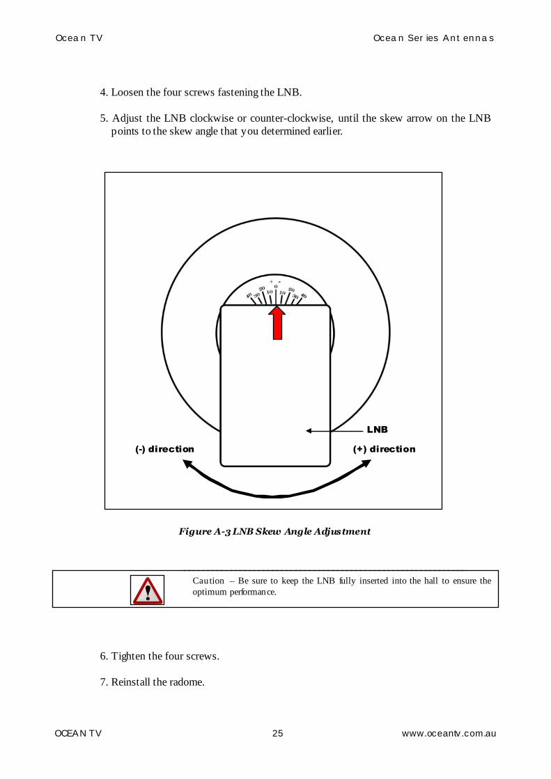
4. Loosen the four screws fastening the LNB.
5. Adjust the LNB clockwise or counter-clockwise, until the skew arrow on the LNBpoints to the skew angle that you determined earlier.
LNB
(+) direction(-) direction
Figure A-3 LNB Skew Angle Adjustment
Caution – Be sure to keep the LNB fully inserted into the hall to ensure theoptimum performance.
6. Tighten the four screws.
7. Reinstall the radome.

Ocean TV Ocean Series Antennas
OCEAN TV 26 www.oceantv.com.au
Satellite Coverage Map
Television satellites are located in fixed positions above the Earth’s equatorand beam TV signals down to certain regions of the planet (not worldwide).To receive TV signals from a satellite, you must be located within that satel-lite’s unique coverage area.
Satellite Coverage Map
Satellite TV broadcast spot beams are aimed at land masses where the bulk of subscribers can befound. Thus, the signal strength decreases as you travel away from the land masses. The furtheryou travel offshore you will require a larger size antenna. Although this information is believedto be correct, Ocean TV has no control over the variations on the actual satellite footprint cover-age. Signal strength and reception can be affected by the weather conditions.
Figure B-1 OPTUS C1/ D3 Coverage Map
NOTE: All of New Zealand - North and South Islands have complete Satellite Coverage

Ocean TV Ocean Series Antennas
OCEAN TV 27 www.oceantv.com.au
Firmware UpgradeIf satellite beam is changed or eliminated, you have to upgrade firmware ofIDU. Ocean TV distributor provides the firmware.
Firmware Upgrade
If antenna cannot search the selected satellite or move incorrectly, you need to change the firm-ware of IDU. To upgrade the firmware, follow the steps below.
1. Prepare the SD memory card.
Figure C-1 SD memory card
2. Before you use the SD memory card, you should format it to “FAT16(Default)”
Please Note:
Ocean TV is continually improving the Firmware installed on the IDU. If you wish to upgradethe firmware, please contact Ocean TV Australia.
A small charge will be made for the supply of a compatible SD Memory Card. Only approvedcompatible memory cards are to be used, the use of a non approved memory card may result in theantenna not working correctly.

Ocean TV Ocean Series Antennas
OCEAN TV 28 www.oceantv.com.au
Figure C-2 Formatting SD memory card
3. After formatting your SD card, copy the new software file from Ocean TV distribu-tor.
4. Turn off the IDU.5. Put your SD memory card into the SD slot of back side of the IDU.
SD_CARD RS-232RECEIVER ANTENNA 12VDC
IN12VDCOUT
SD MemoryCard Slot
Figure C-3 The back of the IDU

Ocean TV Ocean Series Antennas
OCEAN TV 29 www.oceantv.com.au
6. Turn on the IDU. You can see the message “WRITING SOFTWARE” in LCD Dis-play.
Figure C-4 Writing software
7. If you see the message “FINISH TO WRITE”, IDU is finishing the software up-grade. You have to wait until the IDU is restarted.
Figure C-5 Finishing to write
8. Turn off the IDU. Take your SD memory card away from the IDU.
9. Turn on the IDU.
WRITINGSOFTWARE
FINISH TOWRITE

Ocean TV Ocean Series Antennas
OCEAN TV 30 www.oceantv.com.au
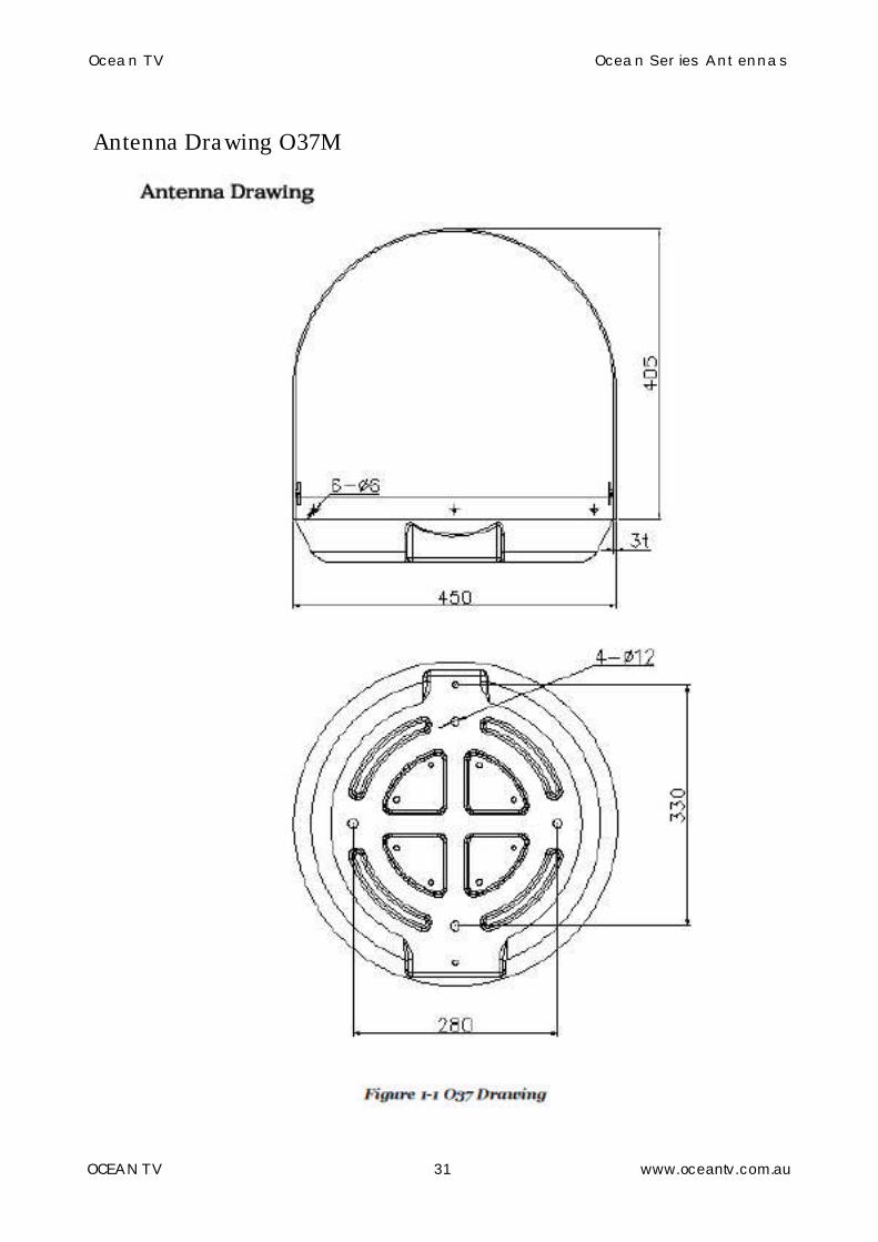
Antenna Drawing
Ocean TV Ocean Series Antennas
OCEAN TV 31 www.oceantv.com.au
Antenna Drawing O37M

Ocean TV Ocean Series Antennas
OCEAN TV 32 www.oceantv.com.au
Antenna Drawing O45M
Figure 1-1 O45M Drawing

Ocean TV Ocean Series Antennas
OCEAN TV 33 www.oceantv.com.au
Appendix E
System Installation Diagrams

Ocean TV Ocean Series Antennas
OCEAN TV 34 www.oceantv.com.au
Antenna
12-24v DC
IDU Indoor Unit
SD Satellite Receiver
Televisions
Ocean TV Installation Diagram
Setup 1
1 Television with SD Satellite Receiver
Coaxial ControlCable
This setup allows 1 SD Satellite TV Receiver to be installed.

Ocean TV Ocean Series Antennas
OCEAN TV 35 www.oceantv.com.au
Antenna
12-24v DC
IDU Indoor Unit
SD Satellite Receivers
Televisions
Ocean TV Installation Diagram
Setup 2
3 Televisions with SD Satellite Receivers
Coaxial ControlCable
This setup allows 1, 2 or 3 individual SD Satellite TVReceivers to be installed, providing separate control andprogramming to be viewed on each Television.

Ocean TV Ocean Series Antennas
OCEAN TV 36 www.oceantv.com.au
Antenna
12-24v DC
IDU Indoor Unit
HD Satellite Receiver
HD Television
Ocean TV Installation Diagram
Setup 3
1 Television with HD Satellite Receiver
Coaxial ControlCable
This setup allows 1 HD Satellite TV Receiver to be installed.

Ocean TV Ocean Series Antennas
OCEAN TV 37 www.oceantv.com.au
Antenna
12-24v DC
IDU Indoor Unit
HD Satellite Receiver
HD Television
Ocean TV Installation Diagram
Setup 3a
1 Television with HD Satellite Receiver
Coaxial ControlCable
This setup allows 1 HD Satellite TV Receiver to be installed.With one less Cable run from Antenna.

Ocean TV Ocean Series Antennas
OCEAN TV 38 www.oceantv.com.au
Antenna
12-24v DC
IDU Indoor Unit
HD Satellite Receiver
HD Television
Ocean TV Installation Diagram
Setup 4
1 Television with HD Satellite Receiver1 Television with SD Satellite Receiver
Coaxial ControlCable
This setup allows 1 HD Satellite TV Receiver and 1 SD SatelliteReceiver to be installed, providing separat e control and programmingon 1 HD Television and 1 SDTelevision.
SD Television
SD Satellite Receiver

Ocean TV Ocean Series Antennas
OCEAN TV 39 www.oceantv.com.au
Antenna
12-24v DC
IDU Indoor Unit
HD Satellite Receivers
Ocean TV Installation Diagram
Setup 5
Multiple Televisions with HD Satellite Receivers
Coaxial ControlCable
This setup allows multiple individual HD Satellite TVReceivers to be installed, providing separate control andprogramming to be viewed on each Television.
The number of Televisions can be from 2 to 16 dependingon the Multi Switch supplied.
Ocean TVHD
Multi Switch
Available in2/4/8/16Outputs
Televisions

Ocean TV Ocean Series Antennas
OCEAN TV 40 www.oceantv.com.au
Appendix F
Satellite Coverage Maps
Satellite Coverage Map
Satellite TV broadcast spot beams are aimed at land masses where the bulk of subscribers can befound. Thus, the signal strength decreases as you travel away from the land masses. The furtheryou travel offshore you will require a larger size antenna. Although this information is believed tobe correct, Ocean TV has no control over the variations on the actual satellite footprint coverage.Signal strength and reception can be affected by the weather conditions.
Foxtel - Austar - Aurora
Optus D3 Satellite Coverage Area
O37M Requires 50dBWO45M Requires 48-49dBW
Foxtel - Austar - Aurora - VAST
Optus C1 Satellite Coverage Area
O37M Requires 50dBWO45M Requires 48-49dBW

Ocean TV Ocean Series Antennas
OCEAN TV 41 www.oceantv.com.au
Select TVIntelsat 8 Satellite Coverage Area
O37M Requires 50dBWO45M Requires 48-49dBW
SkyTV - FreeView NZ
Optus D1 Satellite Coverage Area
O37M Requires 50dBWO45M Requires 48-49dBW

Ocean TV Ocean Series Antennas
OCEAN TV 42 www.oceantv.com.au
Ocean TV Accessories
Compact Multiswitches
Increase the number of HD TV Set top Boxes.
OceanTV O37M, O45M, O60M, O600M and O850MAntennas are all HD/IQ Compatible, but when multi-ple HD/IQ Set Top Boxes are required a CompactMultiswitch can be used. These are available in 2,4, 6, 8 and 12 users.
All are compatible with IQ2 HD Units, and allow fullIQ functions.
Approvals:
Cable Right Angle Adapters
F-59 Plug to F-81 Socket AdaptorRight Angle.
Often used when connecting the Coaxial Cable tothe outputs of the Antenna. Neat, clean and secureconnections, rather than bending the Coaxial Cable.
Foxtel Dual Outlet Wall Plate
Outlet Dual Wallplate 2 x F to F Foxtel designed tomake your installation professional.
Approvals
Build your Own Wall Plate
Blank Wall Plates with 1, 2, 3, 4 or 6 available in-serts. Insert what you need to build a custom wallplate for your entertainment system.
Full Range of Inserts available
Audio Video Scart Lead
Audio Video Lead Scart Out-3RCA 1.5mAudio Video Lead Scart Out-3RCA 3.0m
Approvals
Foxtel F10241Austar A03691
Foxtel F24296
Foxtel F10273, F10430
Ocean TV has a full range of accessories to make installation even easier. Below are just a few,browse www.oceantv.com.au for the latest accessories.
A range of Ocean TV approved LCD Televisions is also available.. www.oceantv.com.au

Ocean TV Ocean Series Antennas
OCEAN TV 43 www.oceantv.com.au
High Quality RG6 Quad Shield Lead withCrimped Connectors
This series is a high quality RG6 Quad shield cabledesigned specifically for use with the new generationof video signals like Pay TV installations, digital tele-vision and traditional analogue video signals.
* RG6 coax cable with Quad shielding - just l ikewhat the pro installers use.* 75Ohm Impedance* Solid copper centre conductor with braid and foilshielding* High quality compression F58 plugs at each end
Available in 4 lengths: 1.5M, 3M, 5M and 10M
HDMI Audio Video Lead
Audio Video Lead, HDMI To HDMI, 1.5, 3, 8m
Foxtel F30507, F30508, F30533Austar A091037
HDMI Lead with Extender - 15m or 20m
Extending your high definition AV signals need notbe an expensive exercise. Normally HDMI cablesshould be kept to a maximum of 5 metres to avoidany signal loss or degradation. Longer runs will re-quire the use of external signal amplifiers.
These affordable HDMI cables have built-in equal-iser boosting the signal strength to enable cablelengths of 15m and 20m without the use of externalpower supply. Cables are ATC certified and is fullyV1.3 compliant and supports 120Hz refresh rate.
Right Angle HDMI Adaptors
Adapts HDMI plug to socket at right angles.Perfect for wall mounted TV applications. Goldplated connections. Two types available:
Right Angle Down HDMI AdaptorRight Angle Up HDMI Adaptor
HDMI Splitter1 Input to 2 Outputs
This tiny switcher routes high definition video (inmultiple resolutions up to 1080p) and digital audiofrom any one of the two sources to display unit. Twoinputs accommodate the simultaneous connection ofupto two high definition video sources, such as sat-ellite systems and HD DVD players. Switching isdone automatically when signal is present on theports or manually via the push button switch on theunit.

Ocean TV Ocean Series Antennas
OCEAN TV 44 www.oceantv.com.au
Hard Wired IR Remote Extension Kit
Hard Wired Infra-Red repeater kit for use in DIY &/orcustom installations, to control an A/V device at aremote location (up to 1.8m). All connections areplug & play, and the kit includes discrete Flat IR tar-get, junction box, double emitter & switch modepower supply. Will work with Foxtel including IQ2
STARTER PACKAll you need for a simple install a basic in cabinetsolution.RPT1041 Connection box withThree IR Transmitter DiodesAn Infra-red receiver block and a 240Vac to 12Vdc P-Pack
Foxtel IQ compatible
IR TRANSMITTERS
IR DIODESSingle or paired Mini IR Transmitter diodes for plac-ing near the equipment you wish to control with IR.
2 meter flexible black cable 3.5mm plugs to suitRPT1041
IR RECEIVER
FLUSH BULLET EYE45x12mmMounts flush into a ½" holeConnects to the RPT1041 moduleThree wire cable 3 meters long
REPLACEMENT EYE50x10mm²2M wire to IR Receiver Black
IR RECEIVER
WALL PLATEOptional IR Receiver moduleStandard wall plate mounting with IR window & re-ception indicatorThree wire screw terminal for Cable run up to 300meters awayConnects to the RPT1041 moduleWhite 115x70x15mm
IR RECEIVER + VOLUME
WALL PLATE 8W ATTENUATOR115x70x70mm wall plate mounting with IR window &reception indicator.Requires RPT1041, cable, etc.With 12 position attenuator knob Adjusts Stereo8W speaker linesIncludes impedance matching for running multiplespeakers too.

Ocean TV Ocean Series Antennas
OCEAN TV 45 www.oceantv.com.au
Pre-programmed Pay TV Set-Top-Box Remote
Control
Designed specifically to ope rate your Pay TV Digital Se tTop Box and give you direct access to the special fea-tures available on the name brand remote.Approx 180mm long.
Features:• Opera tes the FOXTEL® Digital Set Top BoxStock product may vary from picture
HDMI Amplifier Splitter1 Input to 2 Outputs
Play your Ocean TV HD Satellite Receiver to morethan one HDTV. Use this HDMI amplifier splitter toconvert a single HDMI input signal into two identicaland simultaneous output signals, all without losinghigh definition video and audio quality. Single Cablefor both HD Video and Audio.
• Supports HDMI 1.3b• Up to 2.25Gbps/225MHz
HDMI 4 x 2 Switch Matrix Splitter
Multiple HD Devices switchedto Two HD Televisions
Share four HDMI sources between two high defini-tion TVs (HDTV). Essentially, you are able to use allof your high definition sources like Satellite Re-ceiver, Blu-ray, PS3, HD set top boxes in your BoatsSalon Entertainment centre to another HD display ina separate Cabin or Stateroom. Thus saving youthousands from purchasing HD players all overagain! It also reduces cable clutter as well as thehassles of disconnecting and reconnecting sourcesto a TV with only one or two HDMI inputs. Switcheasily between any four HDMI sources with the IRremote included, with up to 16 combinations. Mainsplugpack included.
• Supports HDMI 1.3b• Supports HDTV 1080p• Video amplifier bandwidth 2.25Gbps/225MHz
180 Watt 12VDC to 230VAC Pure Sine Wave
Inverter
Having a pure sine wave output makes this inverterideal for running sensitive items like AC poweredPay Satellite TV Receivers, Notebook Computersand motor-powered devices like fans. The unit con-tinually monitors operational parameters and willalert you to high or low battery voltage, output over-load and over-temperature. A USB socket is alsofitted and supplies 5VDC for charging USB deviceslike MP3 players or digital cameras.

Ocean TV Ocean Series Antennas
OCEAN TV 46 www.oceantv.com.au
Ocean TVSatellite Television
Antennas
© Ocean TV 2010Australia & New Zealand
Dunham House, 2 Massey Street, Gladesville, 2111, Sydney, Australia.Phone: Sydney 0428 250 520 Auckland: 09 889 0882
www.oceantv.com.au [email protected]
Ocean TV Ocean Series Antennas
OCEAN TV 47 www.oceantv.com.au
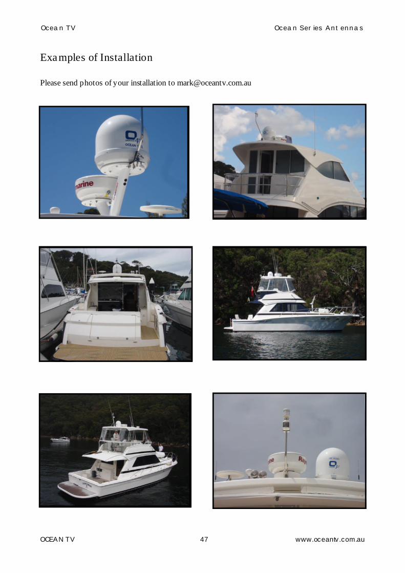
Examples of Installation
Please send photos of your installation to [email protected]