ocean outfall conceptual engineering study
TRANSCRIPT

ATTERIS
CLIENT GUNNS LIMITED
PROJECT BELL BAY PULP MILL PROJECT
DOCUMENT TYPE
REPORT
DOCUMENT TITLE
OCEAN OUTFALL CONCEPTUAL ENGINEERING STUDY
DOCUMENT NO
05-003-R-001
5 3-Mar-06 Updated EJ ST EJ 4 24-Feb-06 Updated DRC EJ EJ 3 21-Dec-05 Re-Issued for Approval DRC EJ EJ 2 8-Dec-05 Re-Issued for Approval DRC EJ EJ 1 30-Nov-05 Re-Issued for Approval DRC EJ EJ 0 22-Sep-05 Issued for Approval DRC EJ EJ B 20-Jun-05 Re-Issued for Comments DRC EJ EJ A 17-Jun-05 Issued for Comments DRC EJ EJ
Revision Date Description Originator Checked Approved
Atteris Pty Ltd
Pipeline Engineers for Shoreline and River Crossings
Level 6
68 St Georges Terrace Perth WA 6000

GUNNS LIMITED
BELL BAY PULP MILL PROJECT
OCEAN OUTFALL CONCEPTUAL ENGINEERING STUDY
ATTERIS
Document 05-003-R-001 Rev 5 Page 1 of 47
TABLE OF CONTENTS
EXECUTIVE SUMMARY.......................................................................................................................... 3
1.0 INTRODUCTION............................................................................................................................. 5 1.1 General............................................................................................................................ 5 1.2 Abbreviations................................................................................................................... 6
2.0 SITE DESCRIPTION....................................................................................................................... 7 2.1 General............................................................................................................................ 7 2.2 Site Visit .......................................................................................................................... 7 2.3 Environmental Sensitivity ................................................................................................ 9 2.4 Topography ................................................................................................................... 11 2.5 Geology......................................................................................................................... 12 2.6 Geomorphology............................................................................................................. 13 2.7 Climatic Conditions........................................................................................................ 13
3.0 CONSTRUCTION METHODS....................................................................................................... 15 3.1 General.......................................................................................................................... 15 3.2 Horizontal Directional Drilling (HDD) ............................................................................. 15 3.3 Open Cut Trenching and Lay ........................................................................................ 19 3.4 Other Construction methods ......................................................................................... 27 3.5 Proposed Construction method..................................................................................... 27
4.0 DESIGN......................................................................................................................................... 28 4.1 General.......................................................................................................................... 28 4.2 Design Data................................................................................................................... 29 4.3 Design Issues – Open Cut Trenching Option................................................................ 29
5.0 ENVIRONMENTAL IMPACT ........................................................................................................ 41 5.1 General.......................................................................................................................... 41 5.2 Onshore......................................................................................................................... 41 5.3 Offshore......................................................................................................................... 42
6.0 SCHEDULE................................................................................................................................... 44 6.1 Preliminary Time Schedule ........................................................................................... 44
7.0 RECOMMENDATIONS................................................................................................................. 44 7.1 Construction Method ..................................................................................................... 44 7.2 Design ........................................................................................................................... 45 7.3 Site Data Collection....................................................................................................... 45
8.0 REFERENCES.............................................................................................................................. 47

GUNNS LIMITED
BELL BAY PULP MILL PROJECT
OCEAN OUTFALL CONCEPTUAL ENGINEERING STUDY
ATTERIS
Document 05-003-R-001 Rev 5 Page 2 of 47
ATTACHMENTS 1. Construction Method Cartoon – HDD 2. Construction Method Cartoon – Open Cut Trenching 3. Concept Drawings:
05-003-D-001 Rev 2 05-003-D-002 Rev 2 05-003-D-004 Rev 0 05-003-D-005 Rev 0
4. Conceptual Hydraulic and Structural Analysis 5. Preliminary Time Schedule

GUNNS LIMITED
BELL BAY PULP MILL PROJECT
OCEAN OUTFALL CONCEPTUAL ENGINEERING STUDY
ATTERIS
Document 05-003-R-001 Rev 5 Page 3 of 47
EXECUTIVE SUMMARY
This report presents the results of a conceptual engineering study in relation to the marine and dune crossing section of an effluent outfall pipeline, an ancillary component of the bleached kraft pulp mill which is planned to be constructed by Gunns Limited near George Town, Tasmania.
A suitable site for the effluent outfall has been identified in an area several hundred metres to the east of the landfall location of the Basslink Power Cable, between Four Mile Bluff and Five Mile Bluff, such that effluent can be discharged into Bass Strait. The site data available supports an outfall alignment with a general north-south orientation, terminating in 20 m water depth, some 2.8 km offshore.
The offshore alignment has been selected on the basis of minimising the disturbance of high and medium relief reef areas, and to construct the 900 mm internal diameter pipeline within sediment and low relief reef areas. The onshore construction footprint has been refined with the objective to minimise the onshore environmental impact. To achieve this it is proposed that the onshore pipeline route utilises the stringing and launching corridor of the marine section when it is installed.
A construction concept has been developed based on temporary trestles, open-cut trenching and auger boring, followed by towing-out prefabricated weight-coated steel pipeline string sections. Preliminary analysis supports the first 1500 m from shore being pre-trenched, of which 750 m from shore should be backfilled after pipeline installation. This represents the proposed concept and should be confirmed with further metocean data at the commencement of detailed design of the project.
As an alternative, and if ambient seastate conditions prove to be favourable for extended periods of time, the outfall could be constructed using GRP pipe material. GRP would eliminate the need for an onshore stringing and launching site, but will require full trenching and backfill offshore.
Alternative construction methods, including HDD, are not technically feasible in view of the combination of ground conditions at the site, the length of the outfall and the diameter of the pipeline.
A decision should be made on whether to use a steel or GRP outfall concept once site geotechnical and metocean information has been collected, on the basis of a cost/risk assessment.

GUNNS LIMITED
BELL BAY PULP MILL PROJECT
OCEAN OUTFALL CONCEPTUAL ENGINEERING STUDY
ATTERIS
Document 05-003-R-001 Rev 5 Page 4 of 47
The impact of the stringing alignment has been minimised by utilising trestles above ground as much as practicable and bending the alignment to avoid the more environmentally sensitive areas.
The synergies between the stringing alignment for the outfall and the onshore pipeline alignment have been realised by utilising the stringing corridor for the onshore alignment. It is also proposed to install a section of the onshore pipeline underneath the sensitive Xanthorrhoea aff. bracteata (EPBC Act listed species) by pipe-jacking. These measures will ensure that onshore environmental impact is minimised.
It is recommended to plan and execute site data collection programs to gain a better understanding of offshore bathymetry and seabed features, offshore geotechnical conditions, and metocean conditions. This data would be collected in accordance with the requirements and conditions of the relevant environmental approvals, and should feed into the next engineering phase, called preliminary engineering design, and support the compilation of an invitation to tender package for construction of the outfall.
The construction duration on site is expected to be between 6 and 8 months for the marine section and approximately 2 to 3 months for the onshore section between the shoreline and the Aerodrome Road.

GUNNS LIMITED
BELL BAY PULP MILL PROJECT
OCEAN OUTFALL CONCEPTUAL ENGINEERING STUDY
ATTERIS
Document 05-003-R-001 Rev 5 Page 5 of 47
1.0 INTRODUCTION
1.1 General
Gunns Limited (Gunns) plans to construct a bleached kraft pulp mill near George Town, Tasmania. The development will include an ocean outfall as part of a pipeline system to discharge treated effluent from the pulp mill operation into Bass Strait. The proposed location of the effluent outfall is east of George Town between Four Mile Bluff and Five Mile Bluff. The assessment of alternative locations for the effluent outfall is undertaken in the Bell Bay Pulp Mill Integrated Impact Statement, December, 2005 (Ref 13).
Gunns has engaged Atteris Pty Ltd to perform a conceptual engineering study for an effluent outfall pipeline on the basis of the following scope:
• review available site data and identify which additional data needs to be acquired to allow the design of the outfall to be undertaken. These include the studies undertaken by other consultants on this and other projects in the area referred to in Section 8.0;
• review, discuss and screen outfall construction methods, and subsequently recommend and develop a technically feasible and cost-effective construction concept;
• develop a conceptual design for the marine section of the outfall pipeline and dune crossing section immediately onshore, and highlight the design issues that require consideration during the preliminary and detail design engineering phases;
• assess the construction period and environmental impacts;
• present a time schedule.

GUNNS LIMITED
BELL BAY PULP MILL PROJECT
OCEAN OUTFALL CONCEPTUAL ENGINEERING STUDY
ATTERIS
Document 05-003-R-001 Rev 5 Page 6 of 47
1.2 Abbreviations
GRP Glass-fibre Reinforced Plastic
HDD Horizontal Directional Dilling
ID Internal Diameter
IIS Integrated Impact Assessment
IMR Inspection, Maintenance and Repair
LAT Lowest Astronomical Tide
PE Polyethylene

GUNNS LIMITED
BELL BAY PULP MILL PROJECT
OCEAN OUTFALL CONCEPTUAL ENGINEERING STUDY
ATTERIS
Document 05-003-R-001 Rev 5 Page 7 of 47
2.0 SITE DESCRIPTION
2.1 General
The site of the proposed ocean outfall is located approximately ten kilometres north-east of George Town, on the north coast of Tasmania. The proposed location for the shore crossing of the outfall pipeline is on Five Mile Beach, approximately 1 km west of Five Mile Bluff, with an approximate north-south orientation (Figures 2.1 and 2.2).
Onshore, the site is characterised by a vegetated dune system. The surrounding land is predominately used for cattle grazing, although a small section of the onshore pipeline route will traverse Crown land.
The nearshore environment is populated with basalt reefs of varying heights, rocky outcrops and bluffs protruding into Bass Strait (Ref 10).
Infrastructures of significance in the vicinity of the proposed outfall are:
• Duke Energy International installed a 14 inch (355 mm) diameter gas pipeline using HDD as part of the Tasmanian Natural Gas Pipeline project, east of Five Mile Bluff, and;
• Basslink has installed a power cable near the proposed outfall alignment. The shore crossing was performed by open cut trenching and the dune system was crossed by HDD. The shore crossing works were completed during the third quarter of 2005.
2.2 Site Visit
A site visit was performed on the 25th May 2005. The visit was conducted by Greg Stanford (Gunns) and Eric Jas (Atteris).
The purpose of the site visit was to obtain a general impression of the shoreline site conditions, including geomorphology, geology, nearshore and onshore conditions, and to generally assess the alignment of the outfall.

GUNNS LIMITED
BELL BAY PULP MILL PROJECT
OCEAN OUTFALL CONCEPTUAL ENGINEERING STUDY
ATTERIS
Document 05-003-R-001 Rev 5 Page 8 of 47
Figure 2.1
Site Overview
Figure 2.2
Aerial Overview

GUNNS LIMITED
BELL BAY PULP MILL PROJECT
OCEAN OUTFALL CONCEPTUAL ENGINEERING STUDY
ATTERIS
Document 05-003-R-001 Rev 5 Page 9 of 47
2.3 Environmental Sensitivity
2.3.1 Marine
The proposed outfall extends into the Boags bioregion, which covers the north coast of Tasmania. The Boags bioregion supports species unique to the region such as the seagrass, posionia australis and green-lip abalone (Ref 2 and 10).
Previous studies have found that the area to the east of the proposed outfall site, Five Mile Bluff, is a pristine marine environment that supports high diversities of fish and invertebrate species. However, although the Five Mile Bluff area is regarded to be of high conservation value, the region is not considered unique from similar marine environments at other locations on the north-east coast of Tasmania (Ref 2 and 10).
Spot dives conducted in the Five Mile Bluff region as part of a seabed mapping survey (Ref. 3 and 10) did not detect the presence of seagrass, although it is possible that seagrass exists on the pipeline alignment (this suggests that the sediment cover in the area is either very thin or highly mobile, or both, given that root systems have not had the chance to develop).
A detailed study of the proposed outfall alignment has been conducted by Aquenal on behalf of Gunns (Ref 10). The study has found that the proposed alignment will pass though areas of sand, low profile reef, medium profile reef and mixed sand / low profile reef.
The Gunns screw shell (Gazameda gunnii), which has been found within the study area, is the only threatened species currently known at the outfall site. There are also a range of protected fish and inverebrates that may occur in the area periodically.
Reflecting the low relief profile of nature of the alignment, fish and sponge densities have generally been found to be low during the study.
Marine mammals and avian species have been considered for the identification of suitable alignments (Ref 13) and construction methods.
Marine pests or other introduced species have not been found at the outfall site.
2.3.2 Onshore
The proposed outfall alignment will cross the edge of the Crown land area which comprises Five Mile Bluff and its immediate surroundings.
A detailed Ecological Vegetation Community assessment has been completed and has identified a number of areas that are vulnerable, rare or endangered. It has been recommended by the authors of the assessment that the onshore alignment of the effluent

GUNNS LIMITED
BELL BAY PULP MILL PROJECT
OCEAN OUTFALL CONCEPTUAL ENGINEERING STUDY
ATTERIS
Document 05-003-R-001 Rev 5 Page 10 of 47
outfall and the footprint associated with the construction of the ocean outfall avoid these areas as far as is practicable (Ref. 9).
Of particular importance is the area south of Aerodrome Road, which has been found to be one of the most significant areas within the entire study, with the presence of at least 6 threatened flora species:
• Acacia ericifolia (rare in Tasmania);
• Calocephaulus lacteus (rare in Tasmania);
• Chorizandra enodis (vulnerable in Tasmania);
• Hypoxis vaginata var. brevistigmata (rare in Tasmania);
• Jancus amabilis (rare in Tasmania) and
• Xanthorrhoea aff. bracteata (vulnerable in Tasmania and Australia, listed species in EPBC Act).
Closer to the shoreline Acacia ulicifolia and Xanthorrhoea aff. bracteata have been found on a number of dunes.
A fauna survey has been undertaken and determined that it was unlikely that any threatened species are located in the affected area. (Ref 13)
Several heritage sites have been identified within the vicinity of the ocean outfall alignment. These sites will not be impacted on the basis of the selected alignment.

GUNNS LIMITED
BELL BAY PULP MILL PROJECT
OCEAN OUTFALL CONCEPTUAL ENGINEERING STUDY
ATTERIS
Document 05-003-R-001 Rev 5 Page 11 of 47
2.4 Topography
Wavecut action has formed a 3 m high cliff at the back of the beach.
The topography of the area immediately onshore from the ocean outfall reveals a number of steep dunes of varying heights up to 35 m above LAT.
Long narrow swales separate the linear dunes. These swales form drainage lines during precipitation. The swales are often close to the watertable, with a damp sandy marshy floor (Ref 8).
Further inland the dunes become wider and rise to a height of 40 m above LAT.
Figure 2.3 Coastal Heath backed by Grazing Land

GUNNS LIMITED
BELL BAY PULP MILL PROJECT
OCEAN OUTFALL CONCEPTUAL ENGINEERING STUDY
ATTERIS
Document 05-003-R-001 Rev 5 Page 12 of 47
2.5 Geology
A geological assessment has been performed to support the conceptual engineering design of the outfall (Ref. 1) and confirmed with onshore geotechnical coring (Ref 12). These ground investigations provide a detailed assessment of the onshore geotechnical conditions which can be expected at the site:
• the beach area consists of sand and basalt cobble overlying solid rock outcrops and emergent cobble reef; the cobble outcrops coalesce into a single reef within 200 m from the shore;
• inshore from 10 m water depth the substrate consists of sand (although it is believed the sand thickness is limited to 1 – 2 m);
• further offshore the seabed consists of cobble and rock outcrops with small accumulations of sediment; the seabed then drops down in a series of terraces until, in about 30 m water depth, the seabed consists of rock covered by patches of coarse gravel and cobbles with rock outcrops;
• there is potentially a palaeo-channel running along the alignment of the proposed outfall pipeline (evidence of this channel may be the existence of the sand-filled channel present in the nearshore area of the site); it is likely that the fill material in the channel consists of coarse gravels, cobbles and sand;
• the basalt which dominates the seabed between the 10 m water depth and the 20 m water depth is expected to be highly to extremely weathered at the surface (top 3m), and unlikely to require pre-fragmentation (drilling & blasting) to allow excavation;
• it is likely that seabed roughness will cause the pipeline to span if the surface is not conditioned;
• in the deeper area it can be reasonably assumed that fractured basalt will be encountered, including the presence of sands, gravels and cobbles, which will compromise the feasibility of applying methods based on HDD;
• the water table within the stringing and onshore pipeline alignment was found to be between 0.8 m and 2.3 m below the surface, however the level of groundwater is expected to fluctuate seasonally.

GUNNS LIMITED
BELL BAY PULP MILL PROJECT
OCEAN OUTFALL CONCEPTUAL ENGINEERING STUDY
ATTERIS
Document 05-003-R-001 Rev 5 Page 13 of 47
2.6 Geomorphology
Erosive action on the northern coast of Tasmania is causing the retreat of the coastline. The dunes in the vicinity of the site are subject to erosion from wind, rain and wave action. The visible erosion is due to wave action during storms.
Pitt & Sherry Pty Ltd has performed a geomorphological assessment examining the historical changes along the coastline from Four Mile Bluff to Five Mile Bluff and the likely future impacts of sea level rise and increased storminess at the proposed effluent pipeline crossing area. (Ref 8).
The report concludes that coastal regression is likely to be 25 m over the next 50 years in the vicinity of the proposed outfall.
2.7 Climatic Conditions
The climatic conditions are grouped in the following categories:
• wind;
• current and tides;
• waves; and,
• precipitation.
There is some limited information available regarding the climatic conditions at the study site.
2.7.1 Wind
Bureau of Meteorology data collected from nearby Low Head over the past 43 years shows that the site is reasonably calm all year round, with winds under 10 knots occurring greater than 50% of the time (Ref 2).
Winds tend to be the strongest during spring and weakest during autumn. Winds blows from the west most of the year round, although north-west, north-east and south-east are also common. Winds greater than 30 knots have a low (<4%) occurrence (Ref 2).

GUNNS LIMITED
BELL BAY PULP MILL PROJECT
OCEAN OUTFALL CONCEPTUAL ENGINEERING STUDY
ATTERIS
Document 05-003-R-001 Rev 5 Page 14 of 47
2.7.2 Currents/Tides
Tides and the currents will affect the stability of the pipeline during installation and during operation, and they also could affect access to the site for equipment during construction, and the impact of any dredged spoil which is temporarily deposited on the seabed.
The north coast of Tasmania is subject to a diurnal tidal pattern, with a full tide cycle every 12.44 hours (Ref 2). The tidal range at the site is approximately 2 m. This will provide some assistance with the excavation of the pipeline trench within the intertidal area.
Currents in the vicinity of Five Mile Bluff are predominantly wind generated. Wind generated current speeds for 10 and 100 year return period conditions are 0.55 m/s and 0.60 m/s respectively (Ref 2). In comparison, the average tide-generated current is approximately 0.08 m/s (Ref 2).
2.7.3 Waves
The waves in the vicinity of Five Mile Bluff are predominately local wind-generated waves (seas). The region is well protected from swell by Tasmania and Flinders and King islands. The dominant swell direction is from the northwest.
The most severe wave conditions are likely to be produced by north-westerly storms, where significant wave heights of 3.8 m and 4.9 m can be expected in a 10 and 100 year storm event (Ref 2). Information on wave periods is not available.
The ambient seastate conditions are a major driver in the selection of floating construction equipment to dredge and backfill the trench, and to install the pipeline. Daily viewing of forecasted wave heights on www.buoyweather.com during the study period (May-November 2005) indicates that ambient seastate drops down to 1 – 2 ft (0.3 – 0.6 m) wave height regularly. Dredging and related marine operations would be feasible at such wave heights.
2.7.4 Precipitation
Rainfall in Tasmania is typically less erosive than on the Australian mainland, as it usually falls in constant light showers rather than irregular storms (Ref 2).

GUNNS LIMITED
BELL BAY PULP MILL PROJECT
OCEAN OUTFALL CONCEPTUAL ENGINEERING STUDY
ATTERIS
Document 05-003-R-001 Rev 5 Page 15 of 47
3.0 CONSTRUCTION METHODS
3.1 General
Pipeline construction methods which are generally utilised for shoreline crossings of this nature are:
• Horizontal Directional Drilling
• Open Cut Trenching
3.2 Horizontal Directional Drilling (HDD)
3.2.1 Concept Description
The construction concept of this method is based on the following main activities (Attachment 1):
• pre-fabrication of pipeline string onshore;
• drilling a pilot hole from onshore to a point offshore, to a diameter of approximately 10 – 12 inches using a slant drilling rig (Figure 3.1); the pilot hole drilling operation is steerable;
• reaming the pilot hole to a size which can accommodate the pipeline, usually between 8 – 16 inches (depending on pipe diameter and geotechnical conditions) over and above the pipeline diameter;
• installation of the pipeline into the reamed borehole by either of the following methods (all of these have been applied successfully on pipeline projects worldwide):
o a winch pontoon pulls the pipe into the borehole from onshore to offshore using a steel wire rope (as pictured in the cartoons in Attachment 1);
o an onshore thrusting machine pushes the pipe inside the borehole from onshore to offshore;
o the pipeline string is towed out over the beach and seabed surface, positioned behind the subsea exit point of the borehole, and subsequently pulled back inside the borehole from offshore to onshore using the drilling rig.

GUNNS LIMITED
BELL BAY PULP MILL PROJECT
OCEAN OUTFALL CONCEPTUAL ENGINEERING STUDY
ATTERIS
Document 05-003-R-001 Rev 5 Page 16 of 47
Figure 3.1 Horizontal Directional Drilling Rig
Many drilled shore crossings have experienced significant problems, causing delays from several months to well over a year, and sometimes creating the need to revert to a traditional open-cut trenching method. The technical reasons for problems during HDD projects are in most cases related to ground conditions.

GUNNS LIMITED
BELL BAY PULP MILL PROJECT
OCEAN OUTFALL CONCEPTUAL ENGINEERING STUDY
ATTERIS
Document 05-003-R-001 Rev 5 Page 17 of 47
Site conditions which greatly affect the feasibility of HDD are:
• presence of gravel banks, cobbles, fractured rock and/or cavities in the drilling trajectory; the drilled and reamed borehole is supported by a drilling fluid only and the described ground conditions will cause this fluid to seep away from the borehole, with a consequential very high risk of borehole collapse;
• where onshore topography and nearshore bathymetry requires the drilling length to be in excess of approximately 1000 - 1500 metres, depending on ground conditions and pipeline (borehole) diameter; drilling lengths of around 2 km have been achieved for crossing rivers (land-to-land drillings), however, drilled pipeline installations across shorelines fit into a category of their own because one end of the crossing is located under water, in often hostile seastate or storm conditions (large waves and/or strong currents), which reduces achievable drilling length.
3.2.2 Feasibility
HDD will not be a viable method for the installation of this outfall pipeline across the shore, for the following reasons:
• onshore coring conducted on the site shows ground conditions consisting of highly weathered, fractured and vesicular basalt rock, the potential presence of a palaeo channel and the consequential presence of cobble and gravel beds along the drilling alignment (Ref 1 & 12), will pose extremely high risks of failure of this installation method, in particular considering the large diameter borehole (approx 1.3 m) which is required;
• the ground conditions alone do not make HDD technically unfeasible, the length of the outfall pipeline (approximately 2800 m) exceeds the length of HDD feasibility, in particular considering the large diameter of the pipeline. For HDD to be applied the alignment will have to be partly drilled (e.g. out to the 10 m water mark) with the remainder installed in a pre-dredged trench (i.e. dredging equipment will be required for the remainder of the outfall section);
• a HDD site footprint for this size project will require a flat hardstand area of between 3000 m2 and 5000 m2. This includes an area for a water basin for storage of fresh water for use during drilling and hole opening operations. An access track suitable for heavy construction equipment will also need to be constructed from the nearest main road to the site. To avoid major impact to the foreshore dunes the HDD entry point onshore will need to be located south of the dune area in the agricultural land

GUNNS LIMITED
BELL BAY PULP MILL PROJECT
OCEAN OUTFALL CONCEPTUAL ENGINEERING STUDY
ATTERIS
Document 05-003-R-001 Rev 5 Page 18 of 47
approximately 650 m from the shoreline. This additional length further diminishes the feasibility of a drilled solution;
• the pipeline string must be pre-fabricated in one continuous length, which offers limited flexibility for the onshore stringing area and will impact the environmentally sensitive area south of Aerodrome Road; and
• the HDD exit point will have an angle with the seafloor of 4 degrees minimum, which will create a large overbend in the pipeline, causing potential pipeline installation and stabilisation problems.
Using smaller, multiple HDD’s has been considered, however it is not considered technically feasible as outlined below.
To cross from behind the dune area and through the surf zone, a length of 1800 metres is required to be drilled. However this has some significant downsides including:
• theoretically, a 300 mm diameter pipeline may be used, however 8 – 10 pipelines are required to be installed to provide the same capacity as the proposed 900 mm ID pipeline.
• 8 to 10 pre-fabricated 2000 m pipestrings would be required to cross into the sensitive area south of Aerodrome Road, vegetation would be required to be cleared for survey lines;
• larger width of dredging is required to situate all the pipelines beyond the surf zone.
• poor results achieved on many drilled shore crossings, including those for small diameter pipelines over relatively short distances, indicate that significant problems can be expected if HDD were pursued for the Pulp Mill Outfall installation, with a high risk of not being able to completing the project. Two previous projects in the vicinity of the proposed outfall have used HDD as part of their construction methodology, however the length and diameter of these crossings were substantially less than the proposed Gunns outfall and it is not appropriate to compare them. One of them, which comprised the installation of a 350 mm diameter pipeline over a length of 860 m experienced significant problems, with a 250% schedule overrun.
Additionally there is still the requirement to prefabricate onshore and tow out to sea the remaining section of the outfall pipeline, requiring the preparation of a stringing and launching site onshore and therefore the dune disturbance will only be marginally reduced.
GUNNS LIMITED
BELL BAY PULP MILL PROJECT
OCEAN OUTFALL CONCEPTUAL ENGINEERING STUDY
ATTERIS
Document 05-003-R-001 Rev 5 Page 19 of 47
3.3 Open Cut Trenching and Lay
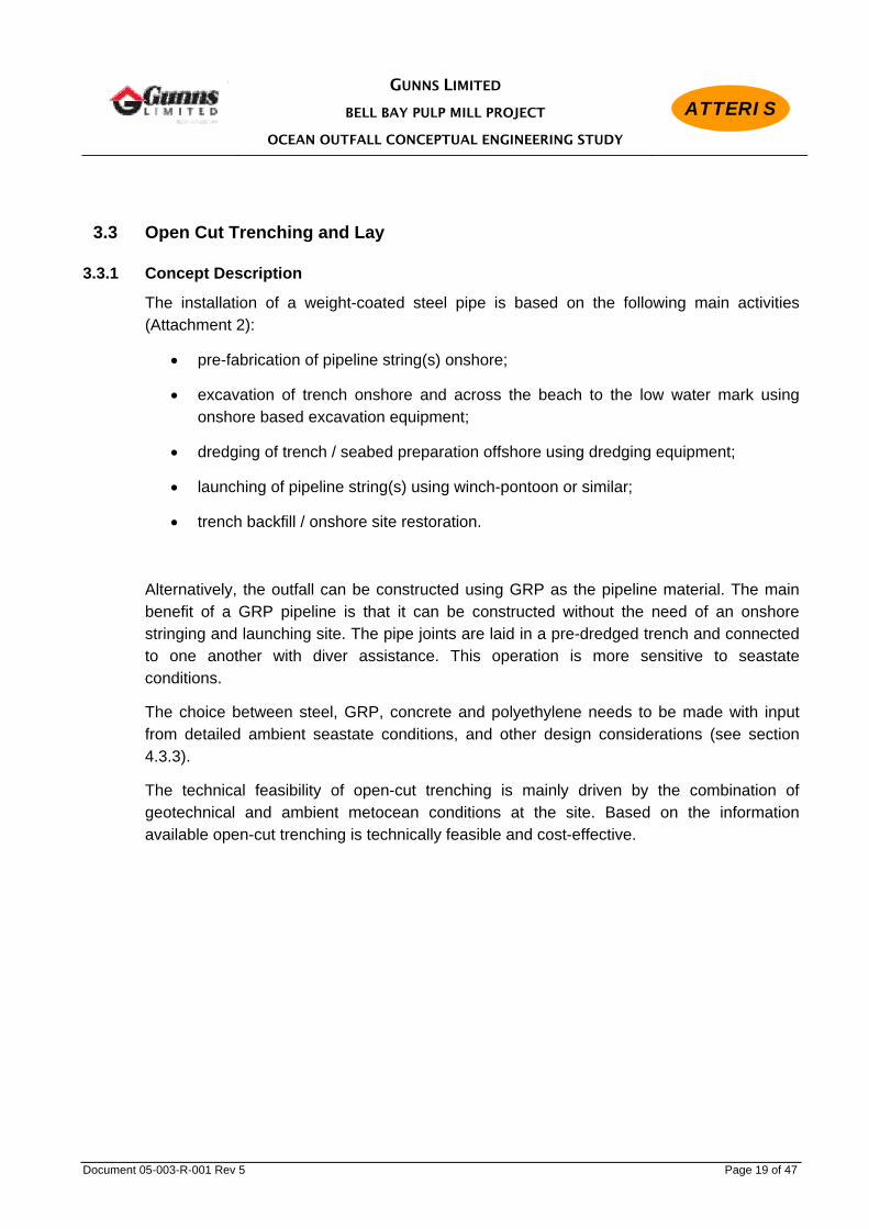
3.3.1 Concept Description
The installation of a weight-coated steel pipe is based on the following main activities (Attachment 2):
• pre-fabrication of pipeline string(s) onshore;
• excavation of trench onshore and across the beach to the low water mark using onshore based excavation equipment;
• dredging of trench / seabed preparation offshore using dredging equipment;
• launching of pipeline string(s) using winch-pontoon or similar;
• trench backfill / onshore site restoration.
Alternatively, the outfall can be constructed using GRP as the pipeline material. The main benefit of a GRP pipeline is that it can be constructed without the need of an onshore stringing and launching site. The pipe joints are laid in a pre-dredged trench and connected to one another with diver assistance. This operation is more sensitive to seastate conditions.
The choice between steel, GRP, concrete and polyethylene needs to be made with input from detailed ambient seastate conditions, and other design considerations (see section 4.3.3).
The technical feasibility of open-cut trenching is mainly driven by the combination of geotechnical and ambient metocean conditions at the site. Based on the information available open-cut trenching is technically feasible and cost-effective.

GUNNS LIMITED
BELL BAY PULP MILL PROJECT
OCEAN OUTFALL CONCEPTUAL ENGINEERING STUDY
ATTERIS
Document 05-003-R-001 Rev 5 Page 20 of 47
Dredging is normally performed using shallow water dredging equipment, such as a cutter suction dredge, or a clamshell or backhoe dredge. In this particular case, backhoe dredging will be the most suitable method for the following reasons:
• a backhoe dredge is capable of dredging weak and weathered rock, and can quite easily be fitted with a subsea rock breaker when stronger rock pockets are encountered;
• the turbidity in the water column from the dredging operations is generally more limited compared with other dredging methods. Backhoe dredging is a mechanical form of dredging whereas a cutter suction dredge dredges material hydraulically with a much greater turbidity (ie mixes the material with water when sucking/pumping the material);
• a backhoe dredge has the ability to accurately create a relatively narrow trench;
• a backhoe dredge is an effective tool to assist with trench backfill.
Figure 3.2 Back Hoe Dredge

GUNNS LIMITED
BELL BAY PULP MILL PROJECT
OCEAN OUTFALL CONCEPTUAL ENGINEERING STUDY
ATTERIS
Document 05-003-R-001 Rev 5 Page 21 of 47
Figure 3.3
Cutter Suction Dredge
3.3.2 Pipestring Launching Concept
Long ocean outfalls constructed with weight-coated steel pipe are usually launched into position from an onshore launchway (roller track) using the bottom-tow method, whereby the pipeline is dragged along the trench bottom and/or seabed with a specifically designed submerged weight.
GUNNS LIMITED
BELL BAY PULP MILL PROJECT
OCEAN OUTFALL CONCEPTUAL ENGINEERING STUDY
ATTERIS
Document 05-003-R-001 Rev 5 Page 22 of 47
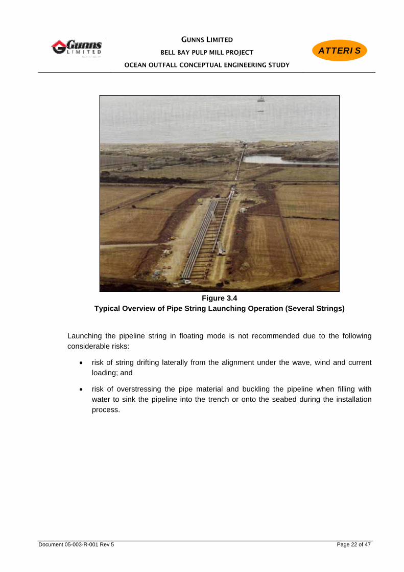
Figure 3.4
Typical Overview of Pipe String Launching Operation (Several Strings)
Launching the pipeline string in floating mode is not recommended due to the following considerable risks:
• risk of string drifting laterally from the alignment under the wave, wind and current loading; and
• risk of overstressing the pipe material and buckling the pipeline when filling with water to sink the pipeline into the trench or onto the seabed during the installation process.

GUNNS LIMITED
BELL BAY PULP MILL PROJECT
OCEAN OUTFALL CONCEPTUAL ENGINEERING STUDY
ATTERIS
Document 05-003-R-001 Rev 5 Page 23 of 47
3.3.3 Pipestringing
The outfall pipeline string should be pre-fabricated in several shorter lengths of 200-250 m sections in view of the onshore environmental constraints and the onshore topography described in Section 2.3. A single pipeline string would impact on many identified environmentally sensitive areas.
The onshore alignment has been planned to avoid the area south of Aerodrome Road which has been identified by other studies as being environmentally sensitive (Ref 9), and a technically suitable stringing and launching site has been identified approximately 1 km onshore (Attachment 3). The alignment has been curved to minimise impact on the areas of threatened, rare and endangered flora species as well as a local heritage site.
Some excavation will be required through the onshore alignment to reduce the elevations traversed by the pipe string. Low terrain areas can be overcome by constructing temporary steel towers or trestles, as shown on the pictures below.
Where excavation is necessary, material will be stockpiled in designated areas clear of identified sensitive vegetated communities.
Additionally, the stringing alignment is to be utilised for the onshore pipeline. Excavations for the stringing alignment will be used as part of the trench for the onshore pipeline installation.
Figure 3.5
Proposed Stringing Site

GUNNS LIMITED
BELL BAY PULP MILL PROJECT
OCEAN OUTFALL CONCEPTUAL ENGINEERING STUDY
ATTERIS
Document 05-003-R-001 Rev 5 Page 24 of 47
Figure 3.6 Temporary Tower Supports for 26” Pipe String Launching
Figure 3.7 Temporary Tower Supports for 36” Pipe String Launching

GUNNS LIMITED
BELL BAY PULP MILL PROJECT
OCEAN OUTFALL CONCEPTUAL ENGINEERING STUDY
ATTERIS
Document 05-003-R-001 Rev 5 Page 25 of 47
Figure 3.8 Temporary Tower Supports for 36” Pipe String Launching

GUNNS LIMITED
BELL BAY PULP MILL PROJECT
OCEAN OUTFALL CONCEPTUAL ENGINEERING STUDY
ATTERIS
Document 05-003-R-001 Rev 5 Page 26 of 47
3.3.4 Application The open-cut method is generally used when the following site conditions exist:
• nearshore shallow bathymetry and onshore moderate topography (area immediately
onshore elevated 10 – 15 m maximum above high water level);
• any geotechnical condition which can readily be excavated and dredged at a reasonable effort (rock above a certain strength can be dredged but would have to be fragmented by rock breaking or drilling & blasting prior to dredging);
• ambient seastate not to exceed 0.5 – 0.6 m wave height and 4 – 5 seconds wave period for at least approximately 50% of the time for a duration of between 4 – 6 months, which would normally be the dredging period;
• a relatively high tidal range generally facilitates open cut; at low tide, onshore equipment can access the intertidal zone, whilst at high tide, floating equipment can access this same area;
• the construction footprint can be minimised through any environmentally sensitive areas.
3.3.5 Feasiblity The open-cut method presents a technically feasible and practical method for constructing the pipeline with the following benefits The geotechnical conditions suggest the presence of a paleo channel which will facilitate the dredging of a trench and eliminate or reduce any need for subsea drilling and blasting.
GUNNS LIMITED
BELL BAY PULP MILL PROJECT
OCEAN OUTFALL CONCEPTUAL ENGINEERING STUDY
ATTERIS
Document 05-003-R-001 Rev 5 Page 27 of 47
3.4 Other Construction methods
3.4.1 Micro-tunnelling
Micro-tunnelling is a steerable form of pipe-jacking. The nature of the machinery and the length of the outfall requires the need for man access to maintain the equipment. The small diameter (900 mm) of the proposed outfall does not provide suitable clearance for man access and therefore it is not considered feasible or safe option for the construction of the entire outfall.
Using microtunnelling to cross the entire dune area (approx 700 m) is also not considered appropriate, as the pipeline corridor has the dual use of providing a launching alignment for the offshore pipeline. It is not practical to launch an offshore an offshore pipeline through such a long tunnel.
3.4.2 Auger boring Auger boring is a non-steerable form of pipe-jacking and is only suitable for installing short length of pipeline ( < 70m depending on diameter). It is not considered a feasible method of constructing the outfall.
3.5 Proposed Construction method
The assessment concludes that the open-cut trenching method is most practical and technically feasible to construct the Pulp Mill Effluent Outfall.

GUNNS LIMITED
BELL BAY PULP MILL PROJECT
OCEAN OUTFALL CONCEPTUAL ENGINEERING STUDY
ATTERIS
Document 05-003-R-001 Rev 5 Page 28 of 47
4.0 DESIGN
4.1 General
The design and construction of the outfall pipeline should follow the following process:
This flow chart also reflects the preliminary time schedule in Attachment 4. The conceptual design engineering work reported in this document identifies the site data which is required to be collected to allow preliminary design engineering to be performed such that the environmental impact assessment be undertaken, approvals granted, and an invitation to tender package can be compiled for the construction contract. The site data collection programs should be based on the selected design and construction concept and the project’s environmental approvals, and the results of the site surveys included in the invitation to tender package. Care should be taken with the wording in the survey reports because they have contractual value (even if they are provided “for information”). Detail design engineering is then performed based on the preliminary engineering, and with input from the construction contractor. Construction engineering is usually performed by the construction contractor with assistance provided by the supervising engineering company on behalf of Gunns Limited, to assure quality of the delivered product.
Conceptual Design Engineering
Offshore Site Data Collection (Site
Survey Programs)
Preliminary Design Engineering
Detail Design Engineering
Tender & Award Outfall Construction
= Current Phase
Construction Engineering &
Construction

GUNNS LIMITED
BELL BAY PULP MILL PROJECT
OCEAN OUTFALL CONCEPTUAL ENGINEERING STUDY
ATTERIS
Document 05-003-R-001 Rev 5 Page 29 of 47
During the current conceptual design engineering stage the design output will be limited to identification of the design issues, and the presentation of a conceptual design.
The following subsections outline the design issues which are relevant to this outfall pipeline, and which will need to be resolved during the preliminary and detail design engineering phases.
4.2 Design Data
The following outfall design data has been communicated to Atteris by Gunns.
Table 4.1 Design Data
Pipeline ID 900 mm
Offshore Extremity (Diffuser Section) 20 m (LAT)
Design Life 50 years
4.3 Design Issues – Open Cut Trenching Option
The following design issues are relevant to this outfall pipeline:
• shoreline geomorphology;
• onshore and offshore environmental constraints;
• route alignment selection;
• pipeline material selection and mechanical design;
• outfall diffuser section design;
• pipeline protection design;
• pipeline on-bottom stability design;
• trench and trench backfill design;
• onshore pipeline design; and,
• construction engineering.

GUNNS LIMITED
BELL BAY PULP MILL PROJECT
OCEAN OUTFALL CONCEPTUAL ENGINEERING STUDY
ATTERIS
Document 05-003-R-001 Rev 5 Page 30 of 47
4.3.1 Shoreline Geomorphology
The shoreline geomorphological study (Ref 8) examines the effect of coastal processes at the proposed outfall site over the 50 year design life of the pipeline.
The study also provides an assessment of the likely impacts of sea level rises and increased storminess associated with climate change on the site.
The front of the dunes has been cut back by marine erosion undermining the upper part of the dunes. This de-stabilises the vegetation, allowing the dunes to become more prone to wind erosion. At the eastern end of the beach the sand has become quite mobile.
The past 60 years has seen the coast retreat 25-30 metres and it is likely to retreat a further 25 metres over the next 50 years. The rate of regression allows for the likely effects of climate change. To ensure the pipeline remains stable through the shore crossing over the design life, the geomorphological study concludes that the pipeline should be laid in a trench that is fully within the highly - extremely weathered basalt layer to the greater of the back of the foredune or 25 m from the back of the existing beach. Consequently, at the toe of the foredune the top of pipe should have 2 metres of cover and at 42m it should have a cover of at least 0.5m.
Revegetation of the site after construction is required to safeguard the environment and to protect the outfall pipeline from erosion of its protective cover.
4.3.2 Route Alignment Selection
Based on the environmental survey data, onshore topography, the seabed bathymetric data and geotechnical information, an alignment must be selected that can be constructed using proven methods and minimises the environmental impact. The route must also provide safe clearance from existing infrastructure in the proximity of the proposed outfall.
The original proposed alignment for stringing and launching of the outfall pipeline involved the pipeline being welded in a continuous straight pipeline string, directly onshore from the proposed offshore alignment (Attachment 3 – 05-003-D-001).
The original alignment has been optimised based on additional onshore and offshore environmental data and selected based on the following (Attachment 3 – 05-003-D-001):
• minimum environmental impact onshore by minimising the length of the onshore pipeline and construction site through the identified sensitive environmental area albeit with the associated increased launching weather risk;
• avoiding as much as possible areas of high relief reef in the nearshore area;

GUNNS LIMITED
BELL BAY PULP MILL PROJECT
OCEAN OUTFALL CONCEPTUAL ENGINEERING STUDY
ATTERIS
Document 05-003-R-001 Rev 5 Page 31 of 47
• using the same alignment for on shore stringing and the onshore pipeline; and
• avoiding artificial obstacles such as ship wrecks.
The most sensitive areas, in particular the Ecological Vegetation Communities south of Aerodrome Road, have been avoided by shortening and curving the alignment, however, there are two points of conflict that required additional consideration to ensure a safe construction and minimal disturbance to sensitive flora.
Xanthorrhoea aff. bracteata To minimise impact on a sand dune supporting Xanthorrhoea aff. bracteata, it is proposed to install part of the onshore pipeline and launching section under the dune by pipe jacking. It is proposed to install a 1.5 - 1.8 m diameter casing pipe underneath the dune, to be used for both the pipeline launching operations and the onshore pipeline. (Attachment 3 – Drawing 05-003-D-005 Rev 0)
Geotechnical investigation results (Ref. 12) confirm the feasibility of employing pipe jacking as a method of crossing the dune with minimal disturbance. The borelogs from the geotechnical investigation (Ref 12) reveal a medium to very dense sand on the crossing alignment. This indicates that pipe jacking is feasible.
Pipe jacking describes the installation of specially made pipes by hydraulically pushing the pipes from a constructed drive shaft. There are various types of equipment that fall under the pipe jacking category, including micro-tunnelling and auger boring.
Micro-tunnelling is a steerable form of pipe jacking and is utilised for long length crossings of varying diameters up to approximately 3.0 m. Micro-tunnelling requires the mobilisation of an tunnel-boring machine and specialist operators.
Auger boring is a non-steerable form of pipe jacking (although some auger bore techniques have limited steering capabilities) and is utilised for shorter length crossings of varying diameters up to approximately 1.5 – 1.8 m. During pipe jacking the spoils are removed back to the drive pit by helically wound auger flights rotating in the jacked pipe.
GUNNS LIMITED
BELL BAY PULP MILL PROJECT
OCEAN OUTFALL CONCEPTUAL ENGINEERING STUDY
ATTERIS
Document 05-003-R-001 Rev 5 Page 32 of 47
Although auger boring is noticeably more economic compared to micro-tunnelling, it has the following downsides:
• the inability to correct any misalignment during jacking limits the applicable crossing length to approximately 50-60 m; the pipeline will naturally move to the material of least resistance;
• given that the face is open, there is a risk of subsidence when boring in sand.
A choice will need to be made between auger boring and micro-tunnelling during preliminary design, prior to issuing invitation to tender documents.
Basslink Easement
The Basslink cable was installed early in 2005 and provides an electricity link from Tasmania to Victoria. Its easement crosses the preferred alignment of the proposed ocean outfall.
In accordance with the wishes of National Grid (the owners of Basslink), the cable will not be exposed during the pipe stringing and launching operation. However to install the onshore section of the outfall pipeline across it, will require exposure, support (using timber beams and straps) and excavation. This is quite common when crossing high voltage cables and can easily be procedurised such that damage to the cable can be avoided.
During both the pipeline stringing and launching operations, and during the onshore pipeline construction, equipment and vehicles will need to cross the Basslink easement. Construction procedures can be implemented to ensure that risk of interference with the Basslink infrastructure is minimised. The pulp mill effluent pipeline easement will necessarily cross the Basslink easement.
4.3.3 Material Selection and Mechanical Design
The pipeline mechanical design involves the selection of the pipeline material and the calculation of the pipeline wall thickness.
The main types of materials used for effluent outfalls are:
• concrete;
• glass-fibre-reinforced plastic (GRP);
• polyethylene (PE); and

GUNNS LIMITED
BELL BAY PULP MILL PROJECT
OCEAN OUTFALL CONCEPTUAL ENGINEERING STUDY
ATTERIS
Document 05-003-R-001 Rev 5 Page 33 of 47
• carbon steel.
The material selected for the outfall is based upon a number of factors including the diameter of the pipeline, construction method and the composition of the product the pipeline will convey.
Concrete and GRP pipes are generally only used for outfalls in protected and sheltered environments, where the pipes can be placed one-by-one and joined together mechanically inside a pre-dredged trench using a crane barge with diver support. GRP is generally preferred over concrete pipes for long outfalls because GRP is a lighter material and easier to handle than concrete, whilst GRP is still sufficiently dense to sink when submerged. The light weight of GRP makes it cheaper to transport to site. Furthermore, as GRP is installed pipe-by-pipe offshore, an onshore stringing area is not required to prefabricate the pipeline.
Unlike steel pipelines, GRP is not subject to corrosion and therefore corrosion protection is not required.
The downsides of using concrete or GRP are:
• the need to pre-dredge the entire length offshore;
• the potential limited workability in relation with ambient seastate conditions;
• in particular for the GRP material the need to backfill the entire length of the trench with engineered backfill to stabilise the pipeline.

GUNNS LIMITED
BELL BAY PULP MILL PROJECT
OCEAN OUTFALL CONCEPTUAL ENGINEERING STUDY
ATTERIS
Document 05-003-R-001 Rev 5 Page 34 of 47
PE is normally used for smaller diameter outfalls of limited length (typically up to 500 - 600 mm in diameter and several hundred metres in length) in sheltered areas where the pipeline string can be floated out and placed onto the seabed by filling it with water and placing weights (gravity anchors) onto the pipeline at discrete intervals. For the Pulp Mill effluent outfall, PE will be impractical and expensive due to its large diameter and extensive length for this material:
• typical wall thickness for a 900 mm ID PE pipe will be 50 – 60 mm which is difficult to butt weld, in particular the tie-in welds in case of launching the outfall string in sections;
• limited tensile strength of PE compared to carbon steel will impose a risk during launching of the pipeline string(s);
• considering the hostile ambient seastate conditions there is a very high risk of damaging the string or failing to install it due to its light weight; a PE pipestring will have to be floated out and sunk to the seabed by filling it with water and placing gravity anchors onto it – it is a certainty that this operation, which will take several weeks, will encounter seastate conditions which may damage the pipeline string;
• in view of the limited submerged weight of the pipeline the stabilisation costs will be excessive.
The recommended material for the outfall is carbon steel with a reinforced concrete weight coating.
Carbon steel is a commonly used material for long sea and ocean outfalls. Steel pipe has the benefit of being a high density and robust material. It is standard industry practise to apply a reinforced concrete weight coating to the outside of the pipeline to ensure that it sinks during installation and to assist in long term stabilisation of the pipeline on the seafloor. Reinforced concrete weight coating can be applied to steel pipe in pipeline coating yards in NSW.
The robustness of steel in combination with continuous concrete coating also provides a level of protection against any mishaps that may occur during installation and does not necessarily require burial after installation for protection. Steel is also surprisingly flexible over longer lengths.
A downside of using carbon steel is that the material is subject to corrosion. However, carbon steel is used extensively for onshore and offshore pipelines and the methods of protecting offshore pipelines from corrosion are highly evolved. Section 4.3.5 discusses the different commonly used method of protecting offshore pipelines from corrosion.

GUNNS LIMITED
BELL BAY PULP MILL PROJECT
OCEAN OUTFALL CONCEPTUAL ENGINEERING STUDY
ATTERIS
Document 05-003-R-001 Rev 5 Page 35 of 47
Based on outfalls of similar size a wall thickness of 0.5-inch (12.7 mm) has been selected at this stage. To achieve a slight negative buoyancy during installation a weight coating thickness of 3-inch (76 mm) has been assumed (concrete density between 2.8 – 3.0 t/cum). Internal and external corrosion coatings are at this stage assumed to be epoxy and asphalt enamel respectively.
Figure 4.1 Concrete Coated Steel Pipeline Strings for Long Sea Outfall
Based on the preliminary investigation, GRP, is recommended for the onshore pipeline. GRP is durable and robust material that is not susceptible to corrosion.
4.3.4 Outfall Diffuser Design
The design of the outfall diffuser section falls outside of the scope of this study, however its design has an impact on the design and construction of the outfall.

GUNNS LIMITED
BELL BAY PULP MILL PROJECT
OCEAN OUTFALL CONCEPTUAL ENGINEERING STUDY
ATTERIS
Document 05-003-R-001 Rev 5 Page 36 of 47
4.3.5 Pipeline Protection Design
Corrosion Protection
It is required when using steel pipelines to apply a corrosion protection coating to the pipeline. The external corrosion coating can take the form of asphalt enamel or a similar product which is protected by the reinforced concrete which is applied on top of it. The requirement for an internal coating will be either be an epoxy coating or a cement lining.
A secondary form of protection against corrosion of the pipeline is cathodic protection. This is usually installed at the interface between the offshore pipeline and the onshore pipeline (ground anode bed). Additionally or optionally, aluminium or zinc bracelet anodes can be installed around the pipeline at several tens of metres intervals, flush with the concrete weight coating surface.
The method of corrosion protection will be determined during the detailed design phase.
External Impact Protection
Additional protection can be achieved by either burying the pipeline into the seabed along its entire length, or by providing a protective cover on top of the pipeline using quarried rock.
The outfall pipeline may be accidentally impacted externally as a result of third party activities, such as commercial vessels (vessel sinking, ship’s anchor impact) and fishing operations (trawl board impact). A risk assessment of impacts on the mill and environment will be undertaken for the IIS (Ref. 13).
Gunns has approached Marine & Safety Tasmania to have the area surrounding the outfall pipeline to be designated ’Not for Anchorage’ in a notice to mariners. This will ensure that the location of the outfall will be published on the relevant marine charts. This will further reduce the likelihood of third party conflict.

GUNNS LIMITED
BELL BAY PULP MILL PROJECT
OCEAN OUTFALL CONCEPTUAL ENGINEERING STUDY
ATTERIS
Document 05-003-R-001 Rev 5 Page 37 of 47
4.3.6 Pipeline Stability Design
The outfall pipeline must be designed such that it is stable under the hydrodynamic loading conditions which it will experience during its lifetime. For a 50 year design life it is standard practise to perform stability analyses using 100 year return period loading conditions, based on the combination of wave induced and steady state near-bottom current velocities.
The first step will be to define this condition. This can be done by using information available from the Bureau of Meteorology supplemented with data from other construction projects which have been undertaken nearby.
For this conceptual design engineering phase the following hydrodynamic loading conditions have been used:
• Significant wave height Hs = 4.9 m (Ref. 2).
• Wave period Tp = 10 s (assumed).
• Wave direction from north-west (assumed).
• Steady state current U = 0.2 m/s (assumed).
• Current direction perpendicular to the pipeline (assumed).
The second step is to perform the analyses considering that the pipeline must be able to be installed with reasonable installation loads (to contain the construction costs), and at the same time that the pipeline has sufficient on-bottom weight to withstand the design hydrodynamic loading conditions.
Weight and buoyancy control of the pipeline can be achieved by applying additional weight to the pipeline. It has proven most cost-effective in these situations to apply a reinforced concrete weight coating around the pipeline. This coating provides abrasion protection during installation and operation, and ensures the pipeline will sink and is stable.
A preliminary analysis indicates that on-bottom stability using pipeline self-weight of a concrete coated steel pipeline can be achieved in water depths greater than 15 m. Inshore of the 15 m water mark additional measures will be required to ensure the integrity of the outfall during design storm conditions. The requirement to achieve a design which does not protrude from the seabed inshore of the 13 – 14 m water mark, where lateral longshore drift occurs (Section 4.3.1) leads to the conclusion that additional stability inshore of 15 m water depth is best achieved by lowering the pipeline into the seabed, in a pre-dredged trench.

GUNNS LIMITED
BELL BAY PULP MILL PROJECT
OCEAN OUTFALL CONCEPTUAL ENGINEERING STUDY
ATTERIS
Document 05-003-R-001 Rev 5 Page 38 of 47
This trench will also provide stability to the pipeline during its installation. The trench length from the back beach out to the 15 m water mark will be approximately 1500 m. A GRP pipeline will require burial over its entire length.
Another important issue requiring attention is the stability of the seabed material. Avoiding areas of unconsolidated sediments will be the best mitigation.
Detailed stability analysis needs to be undertaken during preliminary and detail design to optimise the above concept when the detailed design of the project is undertaken.
4.3.7 Seabed Preparation and Trench Backfill Requirement
Seabed Preparation
Seabed preparation for a concrete coated steel pipeline includes the excavation and dredging of the trench out to the 15 m water depth, and preparation of the seabed between the 15 m and 20 m water depth to ensure the pipeline can be installed safely, and to ensure the pipeline is supported by the seabed without excessive freespans caused by seabed irregularities. For a GRP pipeline a trench will need to be dredged along the entire alignment.
Trench design defines trench depth, bottom width and side slope angle. These are a function of excavation/dredging equipment capable of operating in the site conditions, the geotechnical parameters, pipeline installation method, and pipeline stability requirements (in the case of no trench backfill). At this stage it is assumed that trench depth will be 2 – 3 m and trench bottom width 3 - 5 m. It is expected that trench side slope angles will be between near vertical and 45 degrees. Total estimated trench volume will be approximately 50 thousand cubic metres for a steel pipeline and approximately 100 thousand cubic metres for a GRP pipeline.
Prior to the dredging of the trench, locations will be identified where spoil may be located. Areas of low relief reef and sediment are the preferred area for the location of spoil, and will minimise the environmental impact. Large areas of low relief and sediment were identified in the vicinity of the proposed trench (ref 10), that are suitable for the temporary storage of spoil material. The dredged material will be used to backfill the trench.
The width of the seabed affected during the construction of the outfall is expected to be approximately 50 m.

GUNNS LIMITED
BELL BAY PULP MILL PROJECT
OCEAN OUTFALL CONCEPTUAL ENGINEERING STUDY
ATTERIS
Document 05-003-R-001 Rev 5 Page 39 of 47
Depending on the trench bottom roughness it may be required to install a bedding layer across the trench bottom to protect the pipeline during installation. This can be achieved with a 0.3 m thick gravel or crushed rock layer placed in the trench after dredging of the trench has been completed.
Offshore of the trench, the seabed may need to be prepared using the dredging equipment to remove obstacles which can damage the pipeline and/or cause excessive freespans in the pipeline.
Trench Backfill
Trench backfill is required:
• if there is an unacceptable risk that the pipeline will be lifted out of the trench during storm conditions;
• if an open trench forms a safety hazard to the public or protected fauna and/or to protect the pipeline from damage by the public (e.g. across the beach).
Trench backfill can be achieved using dredged and excavated material. Additionally, engineered fill may be required, in which case a local source (rock quarry) will need to be utilised. The latter may be necessary to avoid liquefaction of sand/silt under wave loading, which may cause the pipeline to float up. This rock would be sourced from the pulp mill site and loaded at the new wharf facility.
At this stage it is assumed that the trench will need to be backfilled through the beach and out to the 10 m water mark, a length of approximately 750 m for a concrete coated steel pipeline, and along the entire alignment for a GRP pipeline (Ref 8).
4.3.8 Onshore Pipeline
The proposed effluent pipeline will be a pressure pipeline with a pumping station located at the pulp mill site.
Consideration of the route and the vertical alignment of the onshore pipeline north of Aerodrome Road has been undertaken to ensure the construction footprint associated with the construction in the vicinity of the sensitive coastline area is minimised. This includes using the same alignment for launching the offshore pipeline as installing the onshore pipeline.
Trench excavation will be kept to a minimum through the use of shields and shoring.

GUNNS LIMITED
BELL BAY PULP MILL PROJECT
OCEAN OUTFALL CONCEPTUAL ENGINEERING STUDY
ATTERIS
Document 05-003-R-001 Rev 5 Page 40 of 47
The geotechnical investigations (Ref 12) have highlighted that the treatment of ground water along the onshore pipe alignment may be an issue that requires management. Ground water can be managed through the use of construction sequencing, de-watering equipment and water table lowering equipment (ground water spears). Excess water can be discharged to natural waterways or the environment through silt traps.
The need for groundwater management is mitigated by scheduling construction works during summer, when the groundwater level is naturally lower.
The onshore pipeline will interface with the outfall at a distance of at least 42 m behind the foredune. This is consistent with the geomorphological assessment (Ref. 8). The offshore pipeline should be installed within the basalt layer to this point.
The report also concludes that there are areas along the trench alignment that consist of hard basalt. These areas may require the use of rock breaker fitted to an excavator and/or blasting to remove the material.
4.3.9 Inspection, Maintenance and Repair
The future operational requirements of the pipeline and outfall must be considered during preliminary design to ensure that inspection and maintenance facilities are installed in appropriate locations and in accordance with the specified IMR philosophy.
4.3.10 Construction Engineering
Construction aspects have to be taken into account throughout any of the design areas. For the shore crossing, particular focus should be on the pipeline buoyancy control to achieve the optimum between minimising pull load versus maximising pipeline specific gravity to achieve pipeline stability for a steel pipeline, and installation engineering of the onshore pipeline section, in particular the crossing of the sand dune and the Basslink Power Cable.

GUNNS LIMITED
BELL BAY PULP MILL PROJECT
OCEAN OUTFALL CONCEPTUAL ENGINEERING STUDY
ATTERIS
Document 05-003-R-001 Rev 5 Page 41 of 47
5.0 ENVIRONMENTAL IMPACT
5.1 General
A rigorous assessment of the environmental features and impacts is made in the Draft Integrated Impact Statement (Ref 13). This section highlights some of the issues that require focus during the construction of the offshore and onshore pipeline.
5.2 Onshore
Native vegetation will need to be removed exposing the ground to erosion from wind and precipitation, and causing dust during dry periods. Erosion can be avoided during works by constructing good temporary drainage and silt traps during site preparation combined with the use of geofabrics. Dust can be suppressed by water spraying during dry weather.
Imported hard stand material is likely to be required, which has the risk of introducing foreign species or diseases such as Phytophthora to the site. Testing the source of hard stand material and the site before construction commences is a common way to eliminate this risk. It is also recommended to implement procedures to ensure that construction equipment, in particular tracked machinery, is cleaned prior to accessing the site.
Utilisation of construction equipment poses the risk of spilling hydrocarbons. Adequate environmental management plans and procedures will need to be prepared and implemented to manage this risk.
Growth of native vegetation should be promoted immediately upon completion of construction to avoid long term erosion.
The short-term impact of open-cut trenching will be higher compared to HDD, however, in the longer term, provided the design is performed adequately, and a sound environmental management plan is developed and implemented, the difference in impact will be negligible.
The onshore stinging alignment crosses through an area that has been identified as a region containing Xanthorrhoea aff. bracteata (EPBC listed) and Acacia ulicifolia which are both considered rare in Tasmania (Ref 11).
The utilisation of the pipeline stringing and launching alignment for the onshore pipeline route corridor minimises the disturbance of the dunes though the area. The pipeline corridor has been optimised through the design process to ensure that level of disturbance to the identified sensitive flora species has been minimised.
The adoption of a pipe jacked dune crossing will mitigate disturbance of the Xanthorrhoea aff. bracteata.

GUNNS LIMITED
BELL BAY PULP MILL PROJECT
OCEAN OUTFALL CONCEPTUAL ENGINEERING STUDY
ATTERIS
Document 05-003-R-001 Rev 5 Page 42 of 47
5.3 Offshore
Dredging and/or blasting causes turbidity in the water column due to the release of small sediment or rock particles. Use of mechanical dredging equipment such as a pontoon-mounted hydraulic excavator (backhoe dredge) will have a significant benefit in this regard compared to hydraulic dredging methods such as cutter suction dredging. The fact that tidal currents are very low at the site has a positive effect in that any turbidity will be limited to the immediate area of the dredging location. The use of silt screens is not recommended in open water conditions given that they are only effective in very sheltered areas such as ports and harbours.
Use of explosives underwater is perceived by many to have major detrimental effects on marine life. This was very much the case in the early days of subsea drilling & blasting. However, these days controlled blasting methods exist which significantly reduce impact onto marine life. Use of controlled drilling & blasting has recently been used in environmentally sensitive areas with great success. During the construction of the Second Gas Trunkline near Dampier, WA for Woodside Energy, explosives were used extensively within a marine national park (Mermaid Sound) with minimal impact to the local environment, which is habitat to marine mammals and sea turtles. Atteris were the designers of the shore crossing and the project managers for the drilling & blasting, and dredging contract, and supervised the nearshore pipeline installation on behalf of Woodside.
However, despite these comments, drilling and blasting is viewed as the last option should the rock offshore prove to strong to be broken with a backhoe dredge fitted with a rock breaker and will be avoided wherever possible.
Similarly to onshore, offshore equipment may accidentally release hydrocarbons into the water. Adequate environmental management plans and procedures will need to be prepared and implemented to manage this risk.
Vessels have been known to transport introduced marine species. Australian maritime laws provide particular quarantine measures for vessels travelling from international water, in regard to this risk and further measures can be specified to domestic vessels to ensure that the risk of introducing foreign marine species is minimised.

GUNNS LIMITED
BELL BAY PULP MILL PROJECT
OCEAN OUTFALL CONCEPTUAL ENGINEERING STUDY
ATTERIS
Document 05-003-R-001 Rev 5 Page 43 of 47
Given favourable geotechnical conditions, the length of the outfall, 2.8 km, would still preclude the use of HDD as single method of constructing the outfall. It would be required to trench the remainder of the offshore alignment and thus the environmental impact of HDD offshore will be higher when compared to open-cut trenching only. This is because over and above the turbidity caused by dredging, HDD for this diameter pipeline (or multiple smaller pipelines) will release large quantities of drilling fluid and drilling cuttings into the ocean.
Given that much of the outfall alignment is in an area of low relief reef rather than the adjacent high relief reef, the environmental impact of the construction of the outfall is minimised.

GUNNS LIMITED
BELL BAY PULP MILL PROJECT
OCEAN OUTFALL CONCEPTUAL ENGINEERING STUDY
ATTERIS
Document 05-003-R-001 Rev 5 Page 44 of 47
6.0 SCHEDULE
6.1 Preliminary Time Schedule
A preliminary time schedule presenting all the design and construction activities is provided in Attachment 5. The following notes are made:
• the schedule is based on key milestone dates of 1st October 2006 for project approval and end of 2008 for completion of commissioning and start-up of the Pulp Mill;
• the schedule is high-level; detailed schedules will have to be prepared for each of the activities;
• individual site data collection activities should be planned such that maximum advantage is taken from favourable weather seasons;
• it is expected that manufacture and coating of the steel linepipe materials will be critical; at this stage an eight month period has been assumed; this will need to be confirmed; should GRP be adopted as the pipe material for the marine section, then the time required for the manufacture of the linepipe is expected to be reduced.
• the limited information available on ambient seastate conditions has precluded performing a detailed assessment of the weather downtime percentage for dredging operations; this is a critical issue in view of the expected limited duration of the good weather season.
7.0 RECOMMENDATIONS
7.1 Construction Method
It is recommended to pursue an open-cut trenching construction method for the Pulp Mill Effluent Outfall. HDD is not considered technically feasible in view of the poor geotechnical conditions for this method, the length of the outfall and the pipeline diameter.
Selection of the pipeline material should be performed once detailed ambient wave data is available, though our preliminary recommendation is to use a weight-coated steel pipeline offshore and GRP onshore.

GUNNS LIMITED
BELL BAY PULP MILL PROJECT
OCEAN OUTFALL CONCEPTUAL ENGINEERING STUDY
ATTERIS
Document 05-003-R-001 Rev 5 Page 45 of 47
The onshore dune crossing should be undertaken by pipe jacking (auger boring or micro-tunnelling).
7.2 Design
A design concept is presented in Attachment 3, based on the need for an onshore pipe stringing and launching area, but showing the offshore pipeline fully trenched and buried. This presents the maximum construction impact. Once the pipe material has been selected either the onshore stringing and launching area or part of the offshore trenching can be omitted from the design. The design issues as listed in Section 4 should be included in the scope for the preliminary design phase, once additional site data has been collected.
7.3 Site Data Collection
A site data collection program will need to be developed and subsequently executed to allow preliminary design to be undertaken, and to allow construction contractors to submit bids. It is appropriate that the environmental approval conditions require this data to be collected and supplied to the relevant government agencies before the detailed design of the effluent outfall pipeline is undertaken.

GUNNS LIMITED
BELL BAY PULP MILL PROJECT
OCEAN OUTFALL CONCEPTUAL ENGINEERING STUDY
ATTERIS
Document 05-003-R-001 Rev 5 Page 46 of 47
The site data collection program should include, in order of priority:
• definition of metocean ambient and design wave and current data;
• nearshore hydrographic survey comprising multibeam bathymetry, side scan sonar, and sub-bottom profiling (shallow seismic);
• offshore geotechnical coring at selected locations, either using a jack-up barge or a diver-operated subsea coring rig deployed from a diving support vessel.

GUNNS LIMITED
BELL BAY PULP MILL PROJECT
OCEAN OUTFALL CONCEPTUAL ENGINEERING STUDY
ATTERIS
Document 05-003-R-001 Rev 5 Page 47 of 47
8.0 REFERENCES
1. Geological Assessment – Shoreline Crossing, Pitt & Sherry, Doc No. H05164H001 Rev A, June 2005.
2. Tasmania Natural Gas Project, Development Proposal and Development Management Plan, Duke Energy International, April 2001.
3. Basslink - Tasmanian Nearshore Survey (Marine), AMOG Consulting, February 2001
4. Wave Climate, General Oceanography & Geomorphology (Marine), AMOG Consulting February 2001.
5. Modelling effluent dispersion in Australian Coastal Waters, C. B. Fandry, S. J. Walker and J.R. Andrewartha, CSIRO, March 1996
6. Duke Energy Pipeline, Borehole Log for Tasmania Shore Crossing - Onshore Borehole, Worley, 30-Oct-2000
7. Environmental Impact Assessment - Siting and design of submarine outfalls, Russell G. Ludwig, 1998.
8. Geomorphological Assessment – Proposed Shoreline Crossing Area – Effluent Pipeline, Pitt & Sherry; 2005.
9. Draft Ecological Vegetation Communities and Quadrat Sampling Locations, Effluent Outfall Pipeline Area, GHD Drawing No. 3116482 dated 23/08/05.
10. Gunns Ltd Pulp Mill, Marine Biological and Pollutant Survey at the Proposed Outfall Site, Aquenal, 2005.
11. Draft Location of threatened species, Effluent Pipeline Outfall area, GHD Drawing number No. 31116482 dated 04/10/05.
12. Proposed Pipeline, Four Mile Bluff, Georgetown; Onshore Geotechnical Investigation, BFP Consultants. November 2005.
13. Gunns Ltd, Bell Bay Pulp Mill, Draft Integrated Impact Statement, December, 2005.

Document 05-003-R-001 Rev 5
Attachment 1
Construction Method Cartoon – HDD

PULLING HEAD
PIPE ROLLERS
PULL WIREWINCH PONTOON
VIRGIN SHORELINE
PILOT HOLE DRILLING
HOLE OPENING
PIPELINE INSTALLATION
DRILL RIG
PILOT HOLE - DRILLING DIRECTION
BOREHOLE - DRILLING DIRECTION
ANCHOR
ANCHOR
PIPELINE
PIPESTRINGPREFABRICATION
ONSHORE
15/06/05E. JAS
ATTERIS TYPICAL PIPELINE SHORE CROSSING CONSTRUCTION( HDD )

Document 05-003-R-001 Rev 5
Attachment 2
Construction Method Cartoon – Open Cut Trenching

15/06/05E. JAS
PIPE STRING FABRICATION
HYDRAULIC EXCAVATORPONTOON MOUNTED
HYDRAULIC EXCAVATOR
PULLING HEAD
PIPELINE
PIPE ROLLERS
PULL WIREWINCH PONTOON
HYDRAULIC EXCAVATOR
PONTOON MOUNTEDHYDRAULIC EXCAVATOR
ROCK SUPPLY VESSEL
PIPELINE
EXCAVATED TRENCH
VIRGIN SHORELINE
TRENCH EXCAVATION / DREDGING
PIPELINE TOWOUT
TRENCH BACKFILL
EXCAVATED TRENCH
ANCHOR
ANCHOR
ATTERIS TYPICAL PIPELINE SHORE CROSSING CONSTRUCTION( OPEN CUT )

Document 05-003-R-001 Rev 5
Attachment 3
Concept Drawing – 05-003-D-001 Rev 2
Concept Drawing -05-003-D-002 Rev 2
Concept Drawing 05-003-D-004 Rev 0
Concept Drawing 05-003-D-005 Rev 0
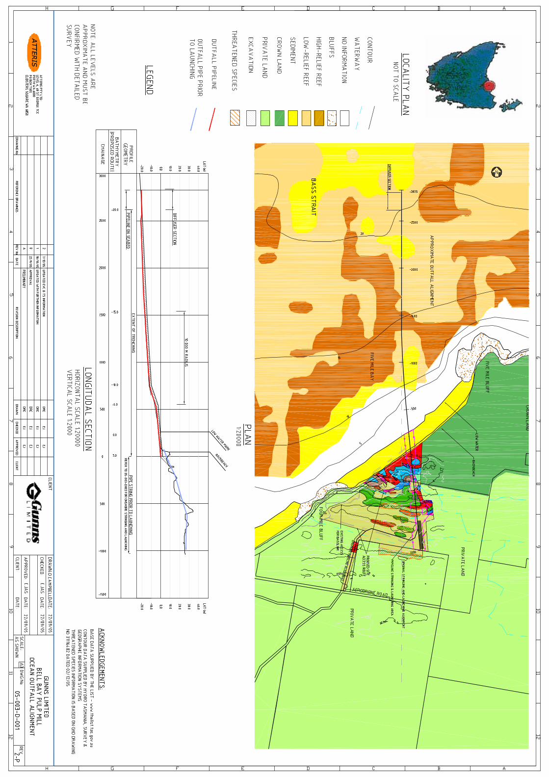


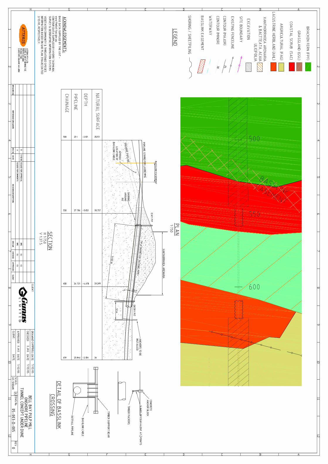

Document 05-003-R-001 Rev 5
Attachment 4
Conceptual Hydraulic and Structural Analysis
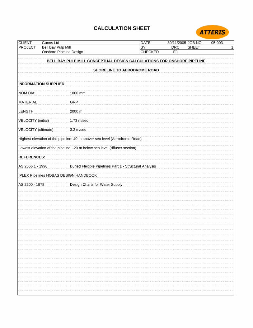
CALCULATION SHEET
CLIENT Gunns Ltd DATE 30/11/2005 JOB NO. 05-003PROJECT Bell Bay Pulp Mill BY DRC SHEET 1
Onshore Pipeline Design CHECKED EJ
BELL BAY PULP MILL CONCEPTUAL DESIGN CALCULATIONS FOR ONSHORE PIPELINE
SHORELINE TO AERODROME ROAD
INFORMATION SUPPLIED
NOM DIA: 1000 mm
MATERIAL GRP
LENGTH 2000 m
VELOCITY (initial) 1.73 m/sec
VELOCITY (ultimate) 3.2 m/sec
Highest elevation of the pipeline: 40 m abover sea level (Aerodrome Road)
Lowest elevation of the pipeline: -20 m below sea level (dffuser section)
REFERENCES:
AS 2566.1 - 1998 Buried Flexible Pipelines Part 1 - Structural Analysis
IPLEX Pipelines HOBAS DESIGN HANDBOOK
AS 2200 - 1978 Design Charts for Water Supply

CALCULATION SHEET
CLIENT Gunns Ltd DATE 30/11/2005 JOB NO. 05-003PROJECT Bell Bay Pulp Mill BY DRC SHEET 2
Onshore Pipeline Design CHECKED EJ
BELL BAY PULP MILL CONCEPTUAL DESIGN CALCULATIONS FOR ONSHORE PIPELINE
SHORELINE TO AERODROME ROAD
HYDRAULIC CALCULATIONS
Information given:
Velocicty (init) 1.73 m/s
Velocity (ult) 3.2 m/s
diameter 1000 mm
hydraulic roughness co-efficient k 0.01 mm
Using Colebrook - White Chart
Adopt SN 10,0000
For the V = 1.73 m/s For V = 3.2 m/s
Q = 1900 l/s Q= 2600 l/s
Friction loss 1.9 m/1000 5.5 m/1000
Minimum head requirements of Aerodrome Road
Use worse case head loss
Pipe Friction2000 m * 5.5 m /1000 m 11 m
Assume 6 bends @ 0.2 m
6 * (0.2m x (3.2 m/s)2 / 2g 0.6 m
Assume 3 valves @ 0.2 m
3 * (0.2m x (3.2 m/s)2 / 2g 0.3 m
Assume additional maintenance structure 2.5 m
Head losses 14.4 m

CALCULATION SHEET
CLIENT Gunns Ltd DATE 30/11/2005 JOB NO. 05-003PROJECT Bell Bay Pulp Mill BY DRC SHEET 3
Onshore Pipeline Design CHECKED EJ
BELL BAY PULP MILL CONCEPTUAL DESIGN CALCULATIONS FOR ONSHORE PIPELINE
SHORELINE TO AERODROME ROAD
HYDRAULIC CALCULATIONS (cont)
At the shoreline the minimum head required is
Static Head 0 m
Dynamic Head
Pipe Friction losses
Pipe Friction2800 m * 5.5 m /1000 m 15.4 m
Assume Diffuser @ 2.0 2 m
Total 17.4 m
Total Head Required at Aerodrome Road
Offshore 17.4 m
Onshore 14.4 m
31.8 m

Document 05-003-R-001 Rev 5
Attachment 5
Preliminary Time Schedule

ID Task Name
1 Key Project Dates
2 Project Approval
3 Commissioning
4
5 Engineering
6 Conceptual Engineering Design
7 Site Data Collection Programs
8 Preliminary Engineering Design
9 Detailed Engineering Design
10
11 Tender & Award Construction
12 Prepare ITT Package
13 Tender & Award Construction Contract
14
15 Construction
16 Construction Engineering
17 Onshore Site Preparation
18 Dune Crossing
19 Supply Coated Linepipe Material
20 Prefabricate Outfall Strings
21 Dredge / Excavate Trench
22 Pipe String Launching Operation
23 Offshore Trench Backfill
24 Construct Onshore Pipeline to Aerodrome Rd
25 Site Restoration
Q1 Q2 Q3 Q4 Q1 Q2 Q3 Q4 Q1 Q2 Q3 Q4 Q1 Q2 Q3 Q4 Q12005 2006 2007 2008 2009
Task
Split
Progress
Milestone
Summary
Project Summary
External Tasks
External Milestone
Deadline
Page 1
Project: Time Schedule Pulp MillDate: Thu 8/12/05