ocean fx user manual - spectrecology · 2018-01-12 · power sequences ... our 3-year warranty...
TRANSCRIPT
Ocean FX Miniature SpectrometerUser Manual
Amy to r
For Product: OCEAN FXDocument: 226-00000-000-01Version: 1.4


226-00000-000-01 i
AMERICAS & WORLD HEADQUARTERS
Phone: +1 727-733-2447Fax: +1 727-733-3962
Sales: [email protected]: [email protected]: [email protected]
EUROPE, MIDDLE EAST & AFRICA
Phone: +31 26-319-0500Fax: +31 26-319-0505Email: [email protected]
Germany : +49 711-341696-0UK : +44 1865-811118France : +33 442-386-588
ASIA
Phone: +86 21-6295-6600Fax: +86 21-6295-6708Email: [email protected]
Japan & Korea: +82 10-8514-3797
www.oceanoptics.comCopyright © 2017 Ocean Optics, Inc.All rights reserved. No part of this publication may be reproduced, stored in a retrieval system, or transmitted, by any means,electronic, mechanical, photocopying, recording, or otherwise, without written permission from Ocean Optics, Inc.TrademarksAll products and services herein are the trademarks, service marks, registered trademarks or registered service marks of theirrespective owners.Limit of LiabilityEvery effort has been made to make this manual as complete and as accurate as possible, but no warranty or fitness is implied. Theinformation provided is on an “as is” basis. Ocean Optics, Inc. shall have neither liability nor responsibility to any person or entitywith respect to any loss or damages arising from the information contained in this manual.
Ocean Optics, Inc.830 Douglas Ave.Dunedin, FL 34698USA
Manufacturing & Logistics4301 Metric Dr.Winter Park, FL 32792USA
Ocean Optics Asia666 Gubei RoadKirin Tower Suite 601BChangning DistrictShanghaiPRC, 200336www.oceanoptics.cn
Sales & SupportGeograaf 246921 EW DuivenThe Netherlands
Manufacturing & LogisticsMaybachstrasse 1173760 OstfildernGermany
226-00000-000-01 ii
Table of ContentsCompliance.................................................................................................................... viWarnings & Cautions ..................................................................................................... viiiAbout This Manual ......................................................................................................... ix
Document Summary .................................................................................................................. ixProduct-Related Support and Documentation ........................................................................... x
Warranty ........................................................................................................................ xi
Chapter 1 ............................................................................................ 1
Introduction........................................................................................1
Product Introduction ....................................................................................................... 1Product Features ....................................................................................................................... 2Typical Applications ................................................................................................................... 3Product Versions........................................................................................................................ 5
Chapter 2 ............................................................................................ 6
How the Ocean FX Spectrometer Works..........................................6
Overview........................................................................................................................ 6
Chapter 3 ............................................................................................ 11
Installation and Setup........................................................................11
What’s In the Box........................................................................................................... 11Ocean FX Installation..................................................................................................... 12
Software Installation................................................................................................................... 12About OceanView ...................................................................................................................... 13Initial Configuration .................................................................................................................... 13Configuration for USB Connection............................................................................................. 14Configuration for Ethernet Connection ...................................................................................... 18Configuration for WiFi Connection............................................................................................. 25Configuration for AP WiFi Connection ....................................................................................... 31Power Sequences...................................................................................................................... 38Experiment Setup ...................................................................................................................... 39Ocean FX Indicator Lights ......................................................................................................... 40Interchangeable Slits ................................................................................................................. 40
About This Manual
226-00000-000-01 iii
Changing the Interchangeable Slits ........................................................................................... 40Accessories.................................................................................................................... 42
Cables and Connectors ............................................................................................................. 42Breakout Box (HR4-BREAKOUT).............................................................................................. 42Light Sources, Cuvette Holders and Other Accessories ........................................................... 42
Measurement Techniques – Typical Set-ups.................................................................. 43Common UV-Vis Applications.................................................................................................... 43Reflectance & Transmission ...................................................................................................... 44Common UV-Vis Reflectance Applications................................................................................ 44Common UV-Vis Transmission Applications ............................................................................. 44Fluorescence.............................................................................................................................. 45Common Fluorescence Applications ......................................................................................... 45Irradiance ................................................................................................................................... 46
Chapter 4 ............................................................................................ 48
Ocean FX Operation with OceanView ..............................................48
Overview........................................................................................................................ 48Launch OceanView........................................................................................................ 48OceanView Main Screen................................................................................................ 49
Connect the Ocean FX in OceanView ....................................................................................... 50Set Acquisition Parameters........................................................................................................ 51Continuous and Single Acquisitions .......................................................................................... 54Save Data .................................................................................................................................. 54Saved Data Panel ...................................................................................................................... 54Projects and Methods ................................................................................................................ 55Spectroscopy Application Wizards ............................................................................................ 56Dark and Reference Measurements.......................................................................................... 56Schematic View ......................................................................................................................... 57
Chapter 5 ............................................................................................ 58
Troubleshooting ................................................................................58
Overview........................................................................................................................ 58Microsoft Windows Operating Systems ..................................................................................... 60Apple Mac OSX Operating Systems.......................................................................................... 60Linux Operating Systems........................................................................................................... 60
Chapter 6 ............................................................................................ 65

About This Manual
226-00000-000-01 iv
Technical Specifications ...................................................................65
Mechanical Diagram ...................................................................................................... 65Absolute Maximum Ratings............................................................................................ 66Performance Specifications............................................................................................ 66Accessory Connectors ................................................................................................... 69
DD4 Accessory Connector......................................................................................................... 69I2C.............................................................................................................................................. 71DB15 Connector Cable (OCEAN FX-CBL-DD4P-DB15P) ........................................................ 71
Chapter 7 ............................................................................................ 73
Calibration..........................................................................................73
Overview........................................................................................................................ 73Wavelength Calibration .................................................................................................. 73
About Wavelength Calibration ................................................................................................... 73Calibrating the Spectrometer Wavelength ................................................................................. 74Preparing for Calibration ............................................................................................................ 74Calibrating the Wavelength of the Spectrometer ....................................................................... 74
Irradiance Calibrations ................................................................................................... 76

About This Manual
226-00000-000-01 v
TablesTable 1 .......................................................................................................................................... ixTable 2 ........................................................................................................................................... 2Table 3 ........................................................................................................................................... 4Table 4 ........................................................................................................................................... 5Table 5 ........................................................................................................................................... 5Table 6 ........................................................................................................................................... 7Table 7 ........................................................................................................................................... 8Table 8 ......................................................................................................................................... 12Table 9 ......................................................................................................................................... 40Table 10 ....................................................................................................................................... 66Table 11 ....................................................................................................................................... 66Table 12 ....................................................................................................................................... 67Table 13 ....................................................................................................................................... 68Table 14 ....................................................................................................................................... 68Table 15 ....................................................................................................................................... 70Table 16 ....................................................................................................................................... 72

About This Manual
226-00000-000-01 vi
ComplianceWARNING
This is a FCC Class A product. In a domestic environment, thisproduct may cause radio interference in which case the user maybe required to take adequate measures.
FCC COMPLIANCEThis equipment has been tested and found to comply with the limits for aClass A digital device, pursuant to Part 15 of the FCC Rules. These limitsare designed to provide reasonable protection against harmful interferencewhen the equipment is operated in a commercial environment. Thisequipment generates uses and can radiate radio frequency energy and, ifnot installed and used in accordance with the instruction manual, maycause harmful interference to radio communications. Operation of thisequipment in a residential area is likely to cause harmful interference inwhich the user will be required to correct the interference at his ownexpense.
WARNING
The authority to operate this equipment is conditioned by therequirement that no modifications will be made to the equipmentunless the changes or modifications are expressly approved by themanufacturer.
WEEE COMPLIANCEThe WEEE symbol on the product indicates that the product must not bedisposed of with normal household waste. Instead, such marked wasteequipment must be disposed of by arranging to return to a designatedcollection point for the recycling of waste electrical and electronicequipment. Separating and recycling this waste equipment at the time ofdisposal will help to conserve natural resources and ensure that theequipment is recycled in a manner that protects human health and theenvironment.

About This Manual
226-00000-000-01 vii
TUV CERTIFICATIONThis device has been tested and complies with the following standards:
EN 61326-1:2013
CISPR 11:2009.A1:2010
CAN ICES-003, issue 6
EMC 2004/108/EC
RoHS-compliant
ISO COMPLIANCEOcean Optics, the industry leader in miniature photonics, has been certified for ISO 9001:2015certification applicable to the design and manufacture of electro-optical equipment since 2009.

About This Manual
226-00000-000-01 viii
Warnings & CautionsWarnings
This device may cause radio interference or may disrupt the operation of nearbyequipment. It may be necessary to take mitigation measures such as re-orienting,relocating or shielding the location.
CautionsCaution: Do not let contaminants get into the bench. Keep the protective cap on the slit
aperture when not connected to an accessory, probe or fiber.
Caution: Only change the slit aperture in a clean environment where contaminants includingdust cannot enter the bench during the procedure.
Caution: Substitution of a component or accessory different from that supplied may result inmeasurement error, equipment damage, increased emissions or decreased immunity.
Caution: Repairs should be undertaken only by personnel trained or authorized by OceanOptics. The device does not contain any user serviceable parts.
Caution: Do not immerse the device in any fluid, place fluids on top of or attempt to clean withliquid detergents or cleaning agents. This may cause an electrical hazard. Do notuse if accidental wetting occurs.
Caution: Do not remove any covers. Doing so may increase the risk of electrical shock orcompromise the integrity of the optical components.
Caution: Do not gas sterilize or autoclave this device.
Caution: Consult local codes and ordinances for proper disposal of equipment and otherconsumable goods.
Caution: The device and/or accessories may not operate correctly if used or stored outside therelevant temperature and humidity ranges described in the Technical Specifications.
Caution: Do not use if device is dropped and/or damaged. Have an authorized servicerepresentative check the device before using again.
Caution: Be sure to install any software BEFORE connecting the spectrometer to your PC. Thesoftware installs the drivers required for spectrometer installation. If you do not installthe software first, the system will not properly recognize the spectrometer.
Caution: To ensure reliable operation, it is recommended that the power supply be attachedprior to inserting the USB connector.
Caution: The user of this spectrometer shall have the sole responsibility for any malfunctionwhich results from improper use, faulty maintenance, improper repair, damage oralteration by anyone other than Ocean Optics or their authorized service personnel.
About This Manual
226-00000-000-01 ix
About This Manual
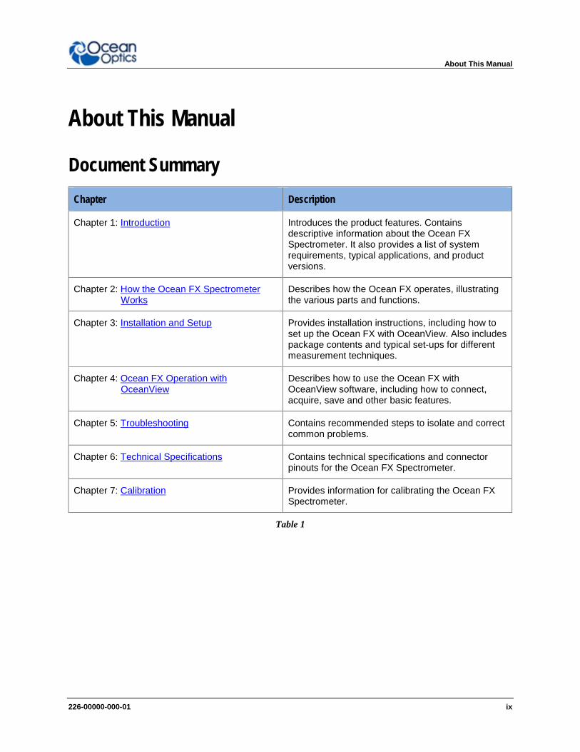
Document SummaryChapter Description
Chapter 1: Introduction Introduces the product features. Containsdescriptive information about the Ocean FXSpectrometer. It also provides a list of systemrequirements, typical applications, and productversions.
Chapter 2: How the Ocean FX SpectrometerWorks
Describes how the Ocean FX operates, illustratingthe various parts and functions.
Chapter 3: Installation and Setup Provides installation instructions, including how toset up the Ocean FX with OceanView. Also includespackage contents and typical set-ups for differentmeasurement techniques.
Chapter 4: Ocean FX Operation withOceanView
Describes how to use the Ocean FX withOceanView software, including how to connect,acquire, save and other basic features.
Chapter 5: Troubleshooting Contains recommended steps to isolate and correctcommon problems.
Chapter 6: Technical Specifications Contains technical specifications and connectorpinouts for the Ocean FX Spectrometer.
Chapter 7: Calibration Provides information for calibrating the Ocean FXSpectrometer.
Table 1
About This Manual
226-00000-000-01 x
ACRONYMS & SYMBOLSMISO Master Input, Slave OutputIEEE Institute of Electronic and Electrical EngineersMOSI Master Output, Slave InputRx ReceiveSPI Serial Peripheral InterfaceTx TransmitUSB Universal Serial BusVusb Voltage, USBWiFi Wireless FidelityFWHM Full Width Half Maximum – optical resolution unitsCMOS Complementary metal oxide semiconductor – type of detectorCCD Charged Coupled Device - type of detectorTEC Thermoelectric Cooling
Product-Related Support and DocumentationYou can access product documentation for Ocean Optics products by visiting our website athttp://www.oceanoptics.com. Go to the Ocean FX product page for general product details,specifications and application notes. Additional technical documents and programs can beaccessed through the Support tab which includes software downloads, getting started guidance,frequently asked questions and technical documents for topics including OceanView Software,light sources, electronic accessories, sampling accessories, fibers & probes, external triggering,changing the slit size and device driver guidance.
Ocean Optics offers a Glossary of spectroscopy terms to help you further understand yourstate-of-the-art products and how they function located in the Knowledge section which alsooffers example setups, application blogs, videos through SpectroscopyTV.com and other waysof learning about spectroscopy.

About This Manual
226-00000-000-01 xi
WarrantyOur 3-Year Warranty covers Ocean Optics miniature fiber-optic spectrometers, spectralsensors, light sources and sampling accessories – regardless of the application – from defectsin materials and workmanship from the date of purchase. It also covers fibers and probes for afull 12 months.
The warranty covers parts and labor needed to repair manufacturing defects that occur duringthe warranty period. We also will cover the costs of shipping warranty-related repairs from ourcustomers to Ocean Optics and from us to our customers. Repairs and upgrades are coveredfor manufacturing defects for 6 months from the date of purchase from Ocean Optics.Normal wear, scratching and cosmetic damage not affecting the performance, bulbs, batteries,consumables and vendor items are not covered by this Ocean Optics limited warranty. Forvendor items, the manufacturer’s warranty terms are in force and vary from product to product.These causes are not covered by this warranty: damage caused by accident, misuse – such asusing an incorrect power supply or power current – abuse, product modification or neglect;damage occurring during shipment; damage resulting from the performance of repairs bysomeone not authorized by Ocean Optics; damage caused by installation of parts that do notconform to Ocean Optics specifications; units not used for their intended purpose; and anyclaims made based on misrepresentations of the seller and costs associated with installation ofthe unit.
Ocean Optics’ liability is limited to the repair or the replacement, at our option, of any defectiveitem and shall not include incidental or consequential damages whatsoever. Ocean Opticsreserves the right to replace a discontinued model with a functionally comparable model.If you require warranty service, please contact the Customer Service Department of OceanOptics at +1.727.733.2447 or fill out a Return Merchandise Authorization (RMA) form located inthe Support section of our website.


226-00000-000-01 1
Chapter 1
IntroductionProduct IntroductionThe Ocean FX is a miniature modular spectrometer with enhanced connectivity and onboardprocessing that is based upon Ocean Optics’ Cross Czerny-Turner design. Ocean FX is builtusing manufacturing techniques that help deliver high thermal stability and low unit to unitvariation without compromising the flexibility and configurability that are the hallmark of thedesign. Features such as interchangeable slits, indicator Lights and simpler device connectorsdeliver more freedom and less frustration. In addition, Ocean FX utilizes a host ofcommunication options including USB 2.0, Gigabit Ethernet, SPI, RS232, 802.11a/b/g/n WiFiand Access Point WiFi.
Ocean FX Spectrometer
1: Introduction
226-00000-000-01 2
Product Features
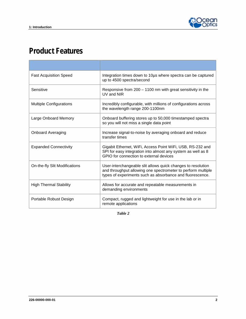
Fast Acquisition Speed Integration times down to 10µs where spectra can be capturedup to 4500 spectra/second
Sensitive Responsive from 200 – 1100 nm with great sensitivity in theUV and NIR
Multiple Configurations Incredibly configurable, with millions of configurations acrossthe wavelength range 200-1100nm
Large Onboard Memory Onboard buffering stores up to 50,000 timestamped spectraso you will not miss a single data point
Onboard Averaging Increase signal-to-noise by averaging onboard and reducetransfer times
Expanded Connectivity Gigabit Ethernet, WiFi, Access Point WiFi, USB, RS-232 andSPI for easy integration into almost any system as well as 8GPIO for connection to external devices
On-the-fly Slit Modifications User-interchangeable slit allows quick changes to resolutionand throughput allowing one spectrometer to perform multipletypes of experiments such as absorbance and fluorescence.
High Thermal Stability Allows for accurate and repeatable measurements indemanding environments
Portable Robust Design Compact, rugged and lightweight for use in the lab or inremote applications
Table 2

1: Introduction
226-00000-000-01 3
Typical ApplicationsApplication Area Examples
Light Laser LED Laser Characterization
LED Measurement
Light Metrology Measurement
Research and Education Applied Research
Basic Research
Teaching Labs for Physics, Chemistry, Biomed
Life Sciences Biotechnology
Medical Diagnostics
Protein and Nucleic Acid Analysis
Materials IdentificationBiomaterial Analysis
Metallurgical Analysis
Polymer Analysis
Semiconductor Materials Analysis
Semiconductors Processing and Thin Film
Metrology
Plasma Monitoring
Process Endpoint Detection
Thickness Measurement
Farm to Table Technologies Agricultural Measurements and Monitoring
Food and Beverage Quality Control
Food Safety

1: Introduction
226-00000-000-01 4
Application Area Examples
Energy TechnologiesBiofuels Analysis
Mining and Exploration
Oil and Petroleum Analysis
Photovoltaic Analysis
Solar Simulators
Anti-Counterfeit Testing and Qualification
Product Identification and Authentication
Quality Control and Process Monitoring Defect Identification
Raw Material Inspection
Verification Testing
Environmental Monitoring Air and Water Quality Analysis
Remote Sensing
Volcanic Research
Table 3
You can find more information about applications of UV-Vis spectroscopy and the Ocean FX atwww.oceanoptics.com.

1: Introduction
226-00000-000-01 5
Specifications SummarySpectral range 200 - 1100 nm (configurable within this range)
Optical resolution 2.39 pixels (FWHM)
SNR (single scan) 290:1
Dynamic range (single scan) 5000:1
Integration time 10 µs – 10 seconds
Scan rate (maximum) 4500 scans/second
Thermal stability 0.11 pixels/ C
Entrance slit 5, 10, 25, 50, 100 or 200 µm width slits
Input fiber connector SMA 905 or FC
Table 4
Product VersionsMany variants of the Ocean FX Spectrometer exist. Ocean Optics offers both preconfiguredunits as well as custom-configured units, enabling you to order a customized spectrometeroptimized for your application. You can determine spectrometer details by looking at the productcode located on the bottom of your spectrometer.
OCEAN FX Preconfigured Models
Model Range(nm)
Slit(μm)
OpticalResolution
(nm)Grating # Lens
GeneralPurpose
OCEAN FX-UV-VIS200-850 25 1.5 1
none
OCEAN FX-UV-VIS-ES L2
OCEAN FX-VIS-NIR350-1000 25 1.5 3
none
OCEAN FX-VIS-NIR-ES L2
ExtendedRange
OCEAN FX-XR1200-1025 25 2 31
none
OCEAN FX-XR1-ES L2
Table 5
For more information and specifications on preconfigured models, see www.oceanoptics.com.

226-00000-000-01 6
Chapter 2
How the Ocean FX SpectrometerWorks
OverviewThis section provides an overview of the Ocean FX spectrometer and how it works from lightentering the slit to the communication of the spectrum to a connected device. It also provides anoverview of all the different possible configurations that are possible, designed to help youoptimize your spectrometer for specific applications.
You’ll find more useful information, including a glossary of spectroscopy and spectrometerterms, on our website at www.oceanoptics.com.
Ocean FX Open Bench
1. Fiber Optic Connector: Light from a fiber enters the optical bench through the SMA905 Connector. The SMA 905 bulkhead provides a precise location for the end of the

2: How the Ocean FX Spectrometer Works
226-00000-000-01 7
optical fiber, slit, absorbing filter and fiber clad mode aperture. While we supply SMAconnectors as standard, FC connectors are also available. See #2 for available options.
2. Interchangeable Slit: Light passes through the installed slit, which actsas the entrance aperture. Slits come in various widths from 5 µm to 200µm and the slit is fixed in the SMA 905 bulkhead to sit against the end ofa fiber. Smaller slit sizes achieve the best optical resolution while largerslits have higher light throughput. Slit size is labeled on the aperture asshown in the photo.
Slit Description Pixel Resolution
INTSMA-5 5-µm wide x 1-mm high 3.0 pixels
INTSMA-10 10-µm wide x 1-mm high 3.2 pixels
INTSMA-25 25-µm wide x 1-mm high 4.2 pixels
INTSMA-50 50-µm wide x 1-mm high 6.5 pixels
INTSMA-100 100-µm wide x 1-mm high 12 pixels
INTSMA-200 200-µm wide x 1-mm high 24 pixels
INTSMA-000 Interchangeable bulkhead with no slit NA
INTSMA-KIT Interchangeable SMA Kit connectors; 5µm; 10µm; 25µm;50µm; 100µm and 200µm
NA
Table 6
Ocean Optics also offers a range of FC connector slits in the same wavelengths, withthe product code INTFC-XXX. An INTFC-KIT is also available. Note that these items aremade to order and have a longer lead time. Contact an Ocean Optics Application SalesEngineer for more details.
► ProcedureTo calculate the optical resolution for your spectrometer:
Find the number of pixels for your detector.Divide the range of the spectrometer by the number of detector pixels.Multiply this number by the pixel resolution from the table above.
Example: Optical Resolution with 50 µm slit, 650 nm Spectral range: 650/2048 x 6.5 =2.1 nm

2: How the Ocean FX Spectrometer Works
226-00000-000-01 8
3. Absorbing Filter (optional): If selected, an absorbing filter is installed between the slitand the aperture in the SMA 905 bulkhead. The filter is used to limit bandwidth of lightentering spectrometer or to balance color. Filters are installed permanently. A filter is fora specific slit. If you anticipate needing the filter with multiple slit sizes,then you must specify this at the time you order. You will know which filteris installed in each slit because of the color-coded dots on the outside asshown in the figure and described in the table below.
Item Code Description Dot 1 Dot 2OF1-BG28 Bandpass filter, transmits >325 and <500 nm blue red
OF1-WG305 Longpass filter; transmits light >305 nm black white
OF1-U325C Bandpass filter, transmits >245 and <390 nm white green
OF1-GG375 Longpass filter; transmits light >375 nm red black
OF1-GG395 Longpass filter; transmits light >395 nm white red
OF1-CGA420 Longpass filter; transmits light >420 nm orange white
OF1-GG475 Longpass filter; transmits light >475 nm green green
OF1-OG515 Longpass filter; transmits light >515 nm pink yellow
OF1-OG550 Longpass filter; transmits light >550 nm orange orange
OF1-OG590 Longpass filter; transmits light >590 nm red pink
OF1-RG695 Longpass filter; transmits light >695 nm white blue
OF1-RG830 Longpass filter; transmits light >830 nm black blue
OF1-CGA1000 Nonfluorescing longpass filter, transmits >1000 nm red green
OF1-CGA760 Nonfluorescing longpass filter, transmits >760 nm blue black
OF1-CGA780 Nonfluorescing longpass filter, transmits >780 nm white yellow
OF1-CGA830 Nonfluorescing longpass filter, transmits >830 nm green orange
OF1-CGA475 Nonfluorescing longpass filter, transmits >475 nm yellow pink
Table 7
4. Collimating Mirror (specify Standard or SAG+): Light reflects from the collimatingmirror as a collimated beam toward the grating. You can opt to install a standard mirroror a NIR-enhancing but UV absorbing SAG+ mirror.
SAG+ mirrors are often specified for fluorescence. These mirrors absorb nearly all UVlight, which reduces the effects of excitation scattering in fluorescence measurements.Unlike typical silver-coated mirrors, the SAG+ mirrors won’t oxidize. They have excellentreflectivity — more than 95% across the VIS-NIR.
Specify standard or SAG+ mirrors when ordering your spectrometer.

2: How the Ocean FX Spectrometer Works
226-00000-000-01 9
Reflectance vs. Wavelength for Aluminum, Gold, and Silver MirrorsBy Bob Mellish in Wikipedia
5. Grating: In optics, a diffraction grating is an optical component with a periodic structurethat splits and diffracts light into several beams traveling in different directions. Thedirections of these beams depend on the spacing of the grating and (most importantly forspectroscopy) the wavelength of the light. In a spectrometer, the grating acts as thedispersive element. Most spectrometers make use of a grating to split the incomingbeam of light into its component wavelengths. This makes use of the optical principle ofdiffraction; that different wavelengths will be transmitted or reflected from a dispersiveelement through varying angles, thereby separating one multi-wavelength beam intomany single-wavelength beams. Typically, a balance must be struck between these twoparameters: as you increase the number of lines/mm on a grating, you increaseresolution but decrease the wavelength range that may be scattered.
Use our online Range and Resolution Calculator to find out how your grating choiceaffects spectral range and optical resolution by viewing the grating efficiency curves.
Gratings Showing Light Diffracted into its Constituent Wavelengths

2: How the Ocean FX Spectrometer Works
226-00000-000-01 10
6. Focusing Mirror (specify standard or SAG+): This mirror focuses first-order spectraon the detector plane. Both the collimating and focusing mirrors are made in-house toguarantee the highest reflectance and the lowest stray light possible. You can opt toinstall a standard or SAG+ mirror. As with the collimating mirror, the mirror type needs tobe specified when ordering.
7. Detector Collection Lens (optional): This cylindrical lens is fixed to the detector tofocus the light onto the detector elements. It increases light-collection efficiency andreduces stray light. It also is useful in a configuration with a large-diameter fiber and slitfor low light-level applications such as fluorescence. Preconfigured Ocean FXspectrometers with a collector lens are available – look for –ES at the end of the name.
8. Detector: Ocean FX utilizes a Hamamatsu S11639-01 linear silicon CMOS arraydetector. Similar to CCD detectors, a CMOS detector also converts incident photonsinto an electric charge. But each CMOS detector pixel has an amplifier attached thattransfers the accumulated charge after a measurement has been made to the A/Dconverter. CMOS detectors can typically operate at much higher speeds than CCDdetectors.
9. Detector Window: The detector includes a clear, quartz window that often includes anorder-sorting filter designed to block second and third order diffraction effects. Lightreflected off the grating can propagate these 2nd and 3rd order effects at whole multiplesof the incident light. Order-sorting filters reject this stray light only allowing the desiredwavelength through to the detector.

226-00000-000-01 11
Chapter 3
Installation and Setup
What’s In the Box
Ocean FX SpectrometerYour Ocean FX spectrometer arrives pre-calibrated and ready to plug and play.
Universal Power SupplyYour Ocean FX spectrometer comes with an external power supply and includes multi-country plugs.
USB CableCable to connect your spectrometer to a USB port on a computer running on a Windows,Mac or Linux operating system. The supplied cable supports USB 3.0.
Ethernet CableCable to connect your spectrometer to your network switch. The supplied cablesupports Gigabit speed.
Getting Started Reference CardThe Ocean Optics Getting Started reference will guide you in ways that you can findfurther information to configure and use your spectrometer and software.
Wavelength Calibration Data SheetEach spectrometer is shipped with a Wavelength Calibration Data Sheet that containsinformation unique to your spectrometer. OceanView reads this calibration data fromyour spectrometer when it interfaces to a computer.
Warranty InformationOcean Optics spectrometer warranty is 3 years and this is printed on the packaging box.

3: Installation and Setup
226-00000-000-01 12
Ocean FX InstallationThe following procedure provides general instructions for getting your new Ocean FXspectrometer up and running.
Software InstallationCaution
Be sure to install the software BEFORE connecting the spectrometer to your PC.The software installs the drivers required for spectrometer installation. If you donot install the software first, the system will not properly recognize thespectrometer.
If you have already connected the Ocean FX to a computer running on aWindows platform prior to installing the operating software, consult theTroubleshooting section for information on correcting a corrupt Ocean FXinstallation.
CautionBe sure that you download the correct software package for your computerversion (32 or 64-bit). See the Frequently Asked Questions in Troubleshootingsection for more information on determining your computer version.
Use OceanView version 1.6.3 and above for Ocean FX. You can use OceanView on thefollowing operating systems.
SoftwareOS
Windows Apple Linux
7 8 8.1 10
OceanView √ √ √ √ OS X Version10.5 or later onIntel processor
Any version released foran x86 or amd64 platformsince 2010
Table 8

3: Installation and Setup
226-00000-000-01 13
About OceanViewOceanView is a user-customizable, advanced acquisition and display program that provides areal-time interface to a variety of signal-processing functions. With OceanView, you have theability to perform spectroscopic measurements (such as absorbance, reflectance, andemission), control all system parameters, collect and display data in real time, and performreference monitoring and time acquisition experiments. Consult the OceanView manual forhardware requirements when using OceanView.
Initial ConfigurationThere are 4 options for accessing the Ocean FX Spectrometer from your computer:
USB port for a local connection (located on the back of the unit) Ethernet connection to your network (located on the back of the unit) WiFi connection to your wireless network Access Point (AP) WiFi direct wireless connection to a PC or Windows-based tablet
(no router or switch needed)
Rear View of Ocean FX Spectrometer
Important NoteBEFORE INITIALIZING ETHERNET OR WIFI, PERFORM USBINITIALIZATION FIRST.
Important NoteIf multiple Ocean FX devices are being used, connection to a particulardevice may require disconnection and connection activities within theDevice Manager of OceanView.
Ethernet
USB

3: Installation and Setup
226-00000-000-01 14
Configuration for USB Connection
Important NoteTo ensure reliable operation, it is recommended that the Ocean FX powersupply be connected prior to inserting the USB connector.
Important NoteTo ensure the USB drivers are automatically loaded, the PC should beconnected to the internet.
1. Install OceanView software on the destination device prior to connecting thespectrometer.
2. Connect the Ocean FX power supply to the Ocean FX and wait for the green indicatorlight to illuminate.
3. Connect the supplied USB cable to the USB connector on the Ocean FX and thedestination device. Wait for device drivers to install before progressing.
4. Start the OceanView application.
5. If applicable, Click “No” for creating a simulation.
6. The Welcome Screen will be displayed. Click the “OK” button.

3: Installation and Setup
226-00000-000-01 15
7. If the USB connection does not automatically connect, click on the device manager icon.
8. Verify that:
a. “Automatically connect to device” and “Automatically connect to remote device” arechecked.
b. “Simulate device if none found” is not checked as shown below.
Click the Exit button.
9. Select the OceanView’s “Schematic” view if not already the active view. This can bedone by clicking Schematic Window on the side bar or by choosing Schematic from theWindow tab.

3: Installation and Setup
226-00000-000-01 16
10. The Ocean FX icon will show up in OceanView’s schematic window as shown below.
3: Installation and Setup
226-00000-000-01 17
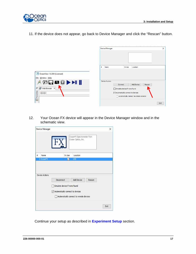
11. If the device does not appear, go back to Device Manager and click the “Rescan” button.
12. Your Ocean FX device will appear in the Device Manager window and in theschematic view.
Continue your setup as described in Experiment Setup section.
3: Installation and Setup
226-00000-000-01 18
Configuration for Ethernet Connection
Important NoteTo ensure reliable operation, it is recommended that the power supply beconnected prior to inserting the Ethernet connector.
Important NoteFor Ethernet to connect properly, the host computer must be wirelesslyconnected to the same router as the Ocean FX Ethernet cable or theWireless functionality within the host computer must be turned OFF.
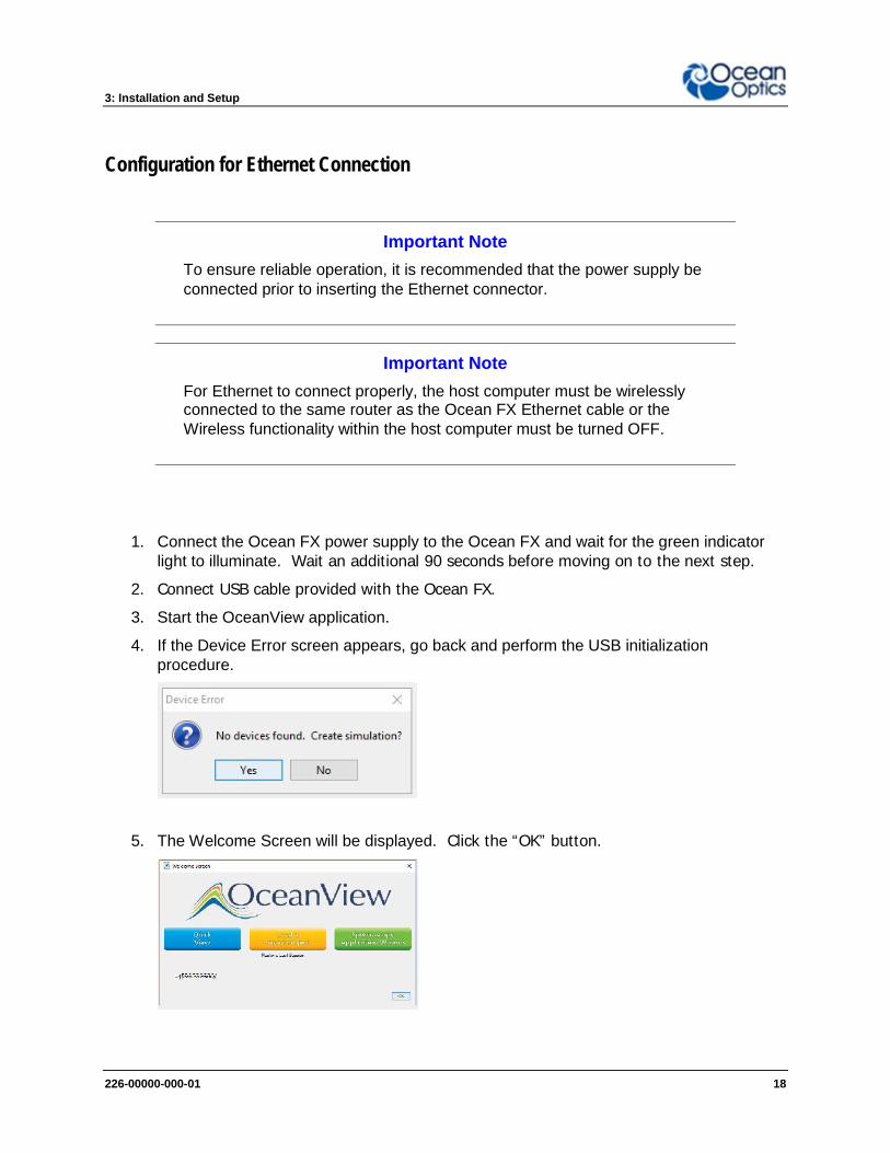
1. Connect the Ocean FX power supply to the Ocean FX and wait for the green indicatorlight to illuminate. Wait an additional 90 seconds before moving on to the next step.
2. Connect USB cable provided with the Ocean FX.
3. Start the OceanView application.
4. If the Device Error screen appears, go back and perform the USB initializationprocedure.
5. The Welcome Screen will be displayed. Click the “OK” button.
3: Installation and Setup
226-00000-000-01 19
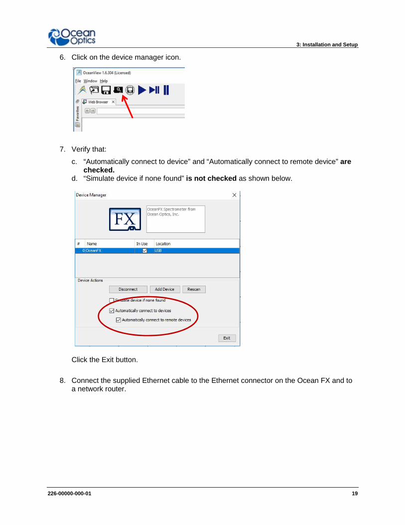
6. Click on the device manager icon.
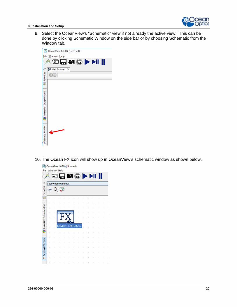
7. Verify that:
c. “Automatically connect to device” and “Automatically connect to remote device” arechecked.
d. “Simulate device if none found” is not checked as shown below.
Click the Exit button.
8. Connect the supplied Ethernet cable to the Ethernet connector on the Ocean FX and toa network router.
3: Installation and Setup
226-00000-000-01 20
9. Select the OceanView’s “Schematic” view if not already the active view. This can bedone by clicking Schematic Window on the side bar or by choosing Schematic from theWindow tab.
10. The Ocean FX icon will show up in OceanView’s schematic window as shown below.

3: Installation and Setup
226-00000-000-01 21
11. In OceanView’s schematic mode, right click on the Ocean FX icon and select “NetworkSetup” which opens the Network Setup window.
12. Select Interface 0. If necessary, click the “Interface Enable” button. If the Ethernetsettings do not appear under Interface 0, then close the window and right click againon the Ocean FX icon and select “Network Setup”. Ethernet options will appearunder Interface 0.
13. Select “Settings” under Ethernet and click “Enable Gigabit Ethernet”.

3: Installation and Setup
226-00000-000-01 22
14. Select “Address” under IPv4 and click “Enable DHCP” and then click the Refresh button.
15. Select “Multicast” under IPv4 and click “Enable multicast”.
16. Select Interface0. Then click “Save as Defaults” which will upload these settings to theOcean FX. Click the Close button.

3: Installation and Setup
226-00000-000-01 23
17. Close OceanView and cycle power on the Ocean FX to enable the new settings. Wait 2minutes then restart OceanView.
18. Click on the device manager icon.
19. In Device Manager, verify that network device has been located. If necessary, click the“Rescan” button to discover the device.

3: Installation and Setup
226-00000-000-01 24
20. Verify the USB device is highlighted. Click on the “Disconnect” button for the USBdevice and exit Device Manager.
21. Disconnect the USB cable and close and restart OceanView. When restarted, theEthernet connection will be activated.
Continue your setup as described in Experiment Setup section.
Important NoteFor future Ethernet use after configuration, wait 2 minutes after powering upthe Ocean FX before opening OceanView.

3: Installation and Setup
226-00000-000-01 25
Configuration for WiFi Connection
Important NoteInitial configuration must be done via USB prior to attempting a WiFiconnection.
Important NoteThe host device with OceanView must be connected to the same WiFi routeras the Ocean FX.
Important NoteBefore attempting WiFi configuration, the Ocean FX must be powered on forat least 2 minutes.
Important NoteThe Ocean FX should be within 15 feet of the wireless router.
1. Connect the Ocean FX power supply to the Ocean FX and wait for the green indicatorlight to illuminate. Wait an additional 90 seconds before moving on to the next step.
2. Connect USB cable provided with the Ocean FX.
3. Start the OceanView application.
4. If the Device Error screen appears, go back and perform the USB initializationprocedure.

3: Installation and Setup
226-00000-000-01 26
5. The Welcome Screen will be displayed. Click the “OK” button.
6. Click on the device manager icon.
7. Verify that:
e. “Automatically connect to device” and “Automatically connect to remote device” arechecked.
f. “Simulate device if none found” is not checked as shown below.
Click the Exit button.

3: Installation and Setup
226-00000-000-01 27
13. In OceanView’s schematic mode, right click on the Ocean FX icon and select “NetworkSetup” which opens the Network Setup window.
14. Select Interface 1. If necessary, click the “Interface Enable” button. If the WiFi settingsdo not appear under Interface 1, then close the window and right click again on theOcean FX icon and select “Network Setup”. WiFi options will appear under Interface 1.

3: Installation and Setup
226-00000-000-01 28
15. Select Security which will show options in the upper right corner of the screen. Select thedesired security either Open or WPA2. If WPA2 is selected, enter the password orphrase that corresponds to your wireless router. Click the “Apply” button.
16. Then select Wireless Network under Interface 1. Mode will default to Client. Enter theSSID for the network device and click the “Apply” button.

3: Installation and Setup
226-00000-000-01 29
17. Select Address. Verify the “Enable DHCP” box is checked. If not, check the box andclick Refresh.
18. Select Multicast. If necessary, click the “Enable Multicast (discovery)” button.

3: Installation and Setup
226-00000-000-01 30
19. Select Interface 1 and then click the “Save as Defaults” button which will upload thesesettings to the Ocean FX. Click the Close button.
20. Disconnect USB cable from the Ocean FX.
21. Close OceanView and cycle power on the Ocean FX to enable the new settings. Wait 2minutes then restart OceanView.
22. If device does not appear correctly, consult the troubleshooting section.
Important NoteWhen using WiFi after initial configuration, wait 2 minutes after powering upthe Ocean FX before opening OceanView.
23. Continue your setup as described in the Experiment Setup section.

3: Installation and Setup
226-00000-000-01 31
Configuration for AP WiFi ConnectionAccess Point (AP) WiFi is similar to Bluetooth in that it is a point-to-point or device-to-deviceconnection and does not need a router or switch.
Important NoteInitial configuration of the Ocean FX must be done via USB prior toattempting AP WiFi connection.
Important NoteNo router or switch is needed but the host device will need to wirelesslyconnect directly to the Ocean FX.
Important NoteBefore attempting AP WiFi configuration, the Ocean FX must be powered onfor at least 2 minutes.
1. Connect the Ocean FX power supply to the Ocean FX and wait for the green indicatorlight to illuminate. Wait an additional 90 seconds before moving on to the next step.
2. Connect USB cable provided with the Ocean FX.
3. Start the OceanView application.
4. If the Device Error screen appears, go back and perform the USB initializationprocedure.
3: Installation and Setup
226-00000-000-01 32
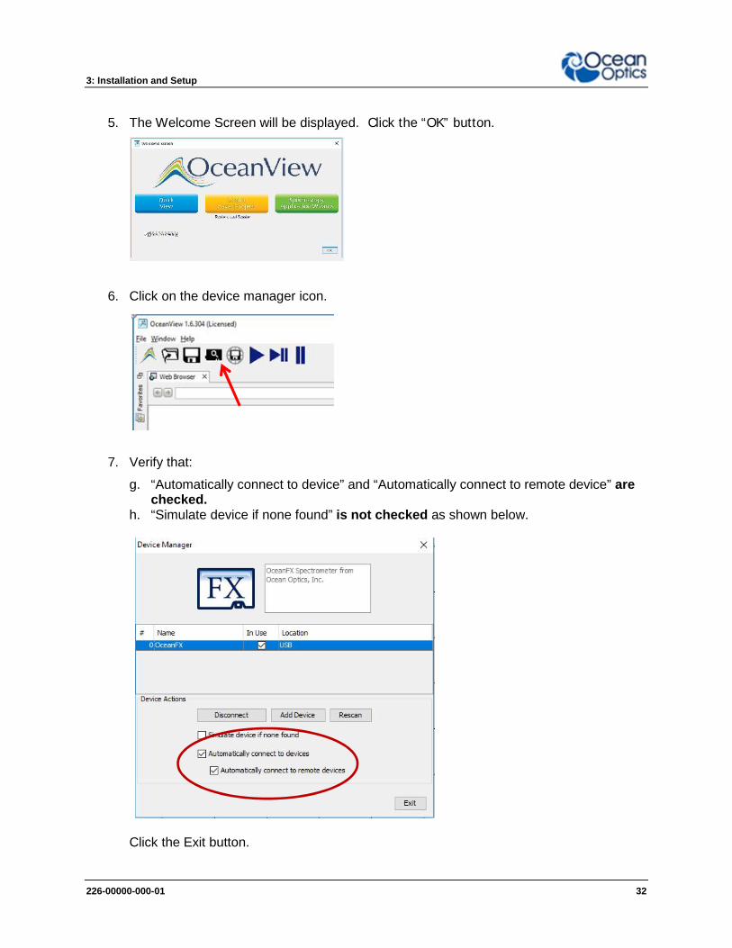
5. The Welcome Screen will be displayed. Click the “OK” button.
6. Click on the device manager icon.
7. Verify that:
g. “Automatically connect to device” and “Automatically connect to remote device” arechecked.
h. “Simulate device if none found” is not checked as shown below.
Click the Exit button.

3: Installation and Setup
226-00000-000-01 33
8. In OceanView’s schematic mode, right click on the Ocean FX icon and select “NetworkSetup” which opens the Network Setup window.
9. Select Interface 1. If necessary, click the “Interface Enable” button. If the WiFi settingsdo not appear under Interface 1, then close the window and right click again on theOcean FX icon and select “Network Setup”. WiFi options will appear under Interface 1.
3: Installation and Setup
226-00000-000-01 34
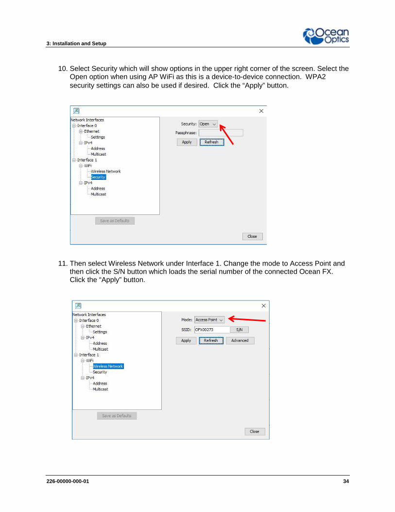
10. Select Security which will show options in the upper right corner of the screen. Select theOpen option when using AP WiFi as this is a device-to-device connection. WPA2security settings can also be used if desired. Click the “Apply” button.
11. Then select Wireless Network under Interface 1. Change the mode to Access Point andthen click the S/N button which loads the serial number of the connected Ocean FX.Click the “Apply” button.

3: Installation and Setup
226-00000-000-01 35
12. Select Address. Verify the “Enable DHCP” box is checked. If not, check the box.
13. Verify that Enable Multicast has been checked. If necessary, click the “Enable Multicast(discovery)” button. Finally, select Interface 1 and then click the “Save as Defaults”button which will save the SSID and passphrase.

3: Installation and Setup
226-00000-000-01 36
14. Select Interface 1 and then click the “Save as Defaults” button which will upload thesesettings to the Ocean FX. Click the Close button.
15. Disconnect USB cable from the Ocean FX.
16. Close OceanView and cycle power on the Ocean FX to enable the new settings. Wait 2minutes.
3: Installation and Setup
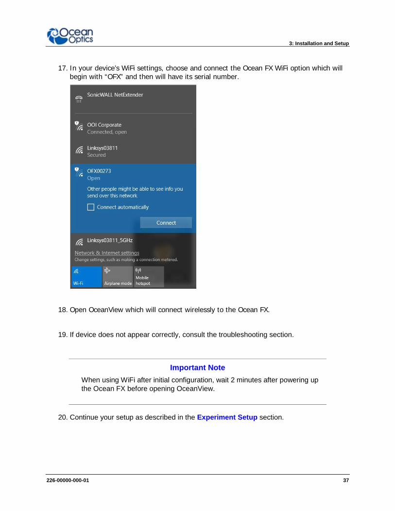
226-00000-000-01 37
17. In your device’s WiFi settings, choose and connect the Ocean FX WiFi option which willbegin with “OFX” and then will have its serial number.
18. Open OceanView which will connect wirelessly to the Ocean FX.
19. If device does not appear correctly, consult the troubleshooting section.
Important NoteWhen using WiFi after initial configuration, wait 2 minutes after powering upthe Ocean FX before opening OceanView.
20. Continue your setup as described in the Experiment Setup section.

3: Installation and Setup
226-00000-000-01 38
Power SequencesPower ON SequencePower up the Ocean FX prior to opening controlling software such as OceanView. Beforestarting software, the following wait times are needed for proper connectivity operation:
USB: No wait timeEthernet: Wait 1 minuteWiFi: Wait 2 minutes
Power OFF SequenceClose the controlling software before powering down the Ocean FX.

3: Installation and Setup
226-00000-000-01 39
Experiment Setup
After the Ocean FX spectrometer is connected in OceanView as described above, you maycontinue the setup as shown below.
Ocean Optics Ocean FX Fiber Optic Spectrometer Typical Set-up
1. Connect any spectroscopy accessories. To find operating instructions for Ocean FX-compatible products (such as light sources, sampling chambers, and probes) go to theTechnical Documents section of the Ocean Optics website under the Support menu.
2. Attach the fiber to the fiber optic connector on the spectrometer.
If you installed the spectrometer operating software prior to connecting the Ocean FX, thesoftware automatically installs the Ocean FX drivers. If the drivers do not successfully install (orif you connected the Ocean FX to the computer before installing the software), consult theTroubleshooting section.
Important Note
The Ocean FX driver appears as USB2000+ to your computer since a commondriver is used to ensure backwards and forwards compatibility. This does notaffect functionality.

3: Installation and Setup
226-00000-000-01 40
Ocean FX Indicator LightsThe Ocean FX features two indicator lights that operate as shown below:
Light Steady Flashing
red Power is on,unit is bootingor in idle state
Unit is acquiring data
green Heartbeat
Table 9
Indicator lights can be turned off in OceanView or by using a firmware command.
Interchangeable SlitsThe Ocean FX offers the capability of changing the slit size to match your measurement andapplication needs. You can order additional replacement slits either individually or as a kit (invarious widths from 5 µm to 200 µm).
Changing the Interchangeable Slits
Caution
Only perform in a clean environment where contaminants cannot enter thebench during the procedure.
Important Note
If your application requires an absorbing filter, one is needed for each slit size.
3: Installation and Setup
226-00000-000-01 41
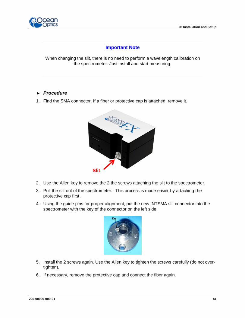
Important Note
When changing the slit, there is no need to perform a wavelength calibration onthe spectrometer. Just install and start measuring.
► Procedure1. Find the SMA connector. If a fiber or protective cap is attached, remove it.
2. Use the Allen key to remove the 2 the screws attaching the slit to the spectrometer.
3. Pull the slit out of the spectrometer. This process is made easier by attaching theprotective cap first.
4. Using the guide pins for proper alignment, put the new INTSMA slit connector into thespectrometer with the key of the connector on the left side.
5. Install the 2 screws again. Use the Allen key to tighten the screws carefully (do not over-tighten).
6. If necessary, remove the protective cap and connect the fiber again.
Slit

3: Installation and Setup
226-00000-000-01 42
AccessoriesOcean Optics provides a range of standard cables and accessories that connect the Ocean FXto our large range of sampling and light source accessories utilizing the DD4 connector on thefront of the Ocean FX spectrometer. Items specifically designed for the Ocean FX are describedhere; they are not provided with the Ocean FX spectrometer and must be purchased separately.Visit us at www.oceanoptics.com for a complete list of products available for all yourspectroscopy needs.
Cables and ConnectorsCables are available to connect your Ocean FX Spectrometer to accessories such as lightsources. Cable pinouts and descriptions are located in the Technical Specifications chapter.
Breakout Box (HR4-BREAKOUT)The Breakout Box is a passive module that separates the signals from the Ocean FX’s DD4 40-pin connector to an array of standard connectors and headers, enabling functionality with a widerange of accessories. In addition to the accessory connector, the breakout box features a circuitboard based on a neutral breadboard pattern that allows custom circuitry to be prototyped onthe board itself. See the Ocean Optics website for installation and operation instructions.
Light Sources, Cuvette Holders and Other AccessoriesOcean Optics supplies a large range of accessories for use with our spectrometers. Thisincludes:
Fibers Light Sources Integrated Sampling Systems Cuvettes, including microfluidic cuvettes Filter Holders & Filters including Low Pass, Band Pass and High Pass

3: Installation and Setup
226-00000-000-01 43
Measurement Techniques – Typical Set-upsThe Ocean FX, in conjunction with Ocean Optics light sources and sampling accessories, canbe used for many different measurement techniques. One of the key advantages of modularfiber optic spectroscopy is that you can change components of the system without having to buya whole new system. Here, we show a range of typical UV-VIS set ups for basic spectroscopytechniques. Additional measurement techniques are presented on the Ocean Optics website.
Absorbance
Typical Absorbance Set Up
Common UV-Vis Applications Quantification of DNA & proteins in life science samples Concentration of solutions & gaseous samples Identification of trace gases in a mixture
Absorbance is typically a relative measurement, comparing the spectrumfrom the sample to that of a reference. Absorbance is commonly used forconcentration measurements and for identifying components in mixtures.The absorbance measurement scales the response logarithmically.Connect the to our cuvette accessories via the SMA Adaptor accessory totake a liquid sample Absorbance measurement, or mount it directly againstthe sample with a light source on the opposite side for solid sampling.

3: Installation and Setup
226-00000-000-01 44
Reflectance & Transmission
A Reflectance Set Up with Probe, Reflectance Standard and Probe Holder
Common UV-Vis Reflectance Applications Diffuse and Specular Color Measurements Process control for Surface quality of metals Thin film and semiconductor metrology
Common UV-Vis Transmission Applications Turbidity measurements of chemical solutions Measuring the transmission efficiency of optics and glass
Reflectance spectroscopy compares the relative level of light reflected offa sample compared with a reference (given as a percentage of thereference spectrum at each wavelength). A reflectance standard is used toset the reference level of 100%. Transmission is similar but compares thelight transmitted through a sample relative to a reference rather thanreflected off it. Typically, reflectance uses a fiber optic probe attached to alight source and a spectrometer, but measurements can also be done bothin free-space or with the SMA Adaptor accessory. Transmission setupsare usually the same as Absorbance setups.
3: Installation and Setup
226-00000-000-01 45
Fluorescence
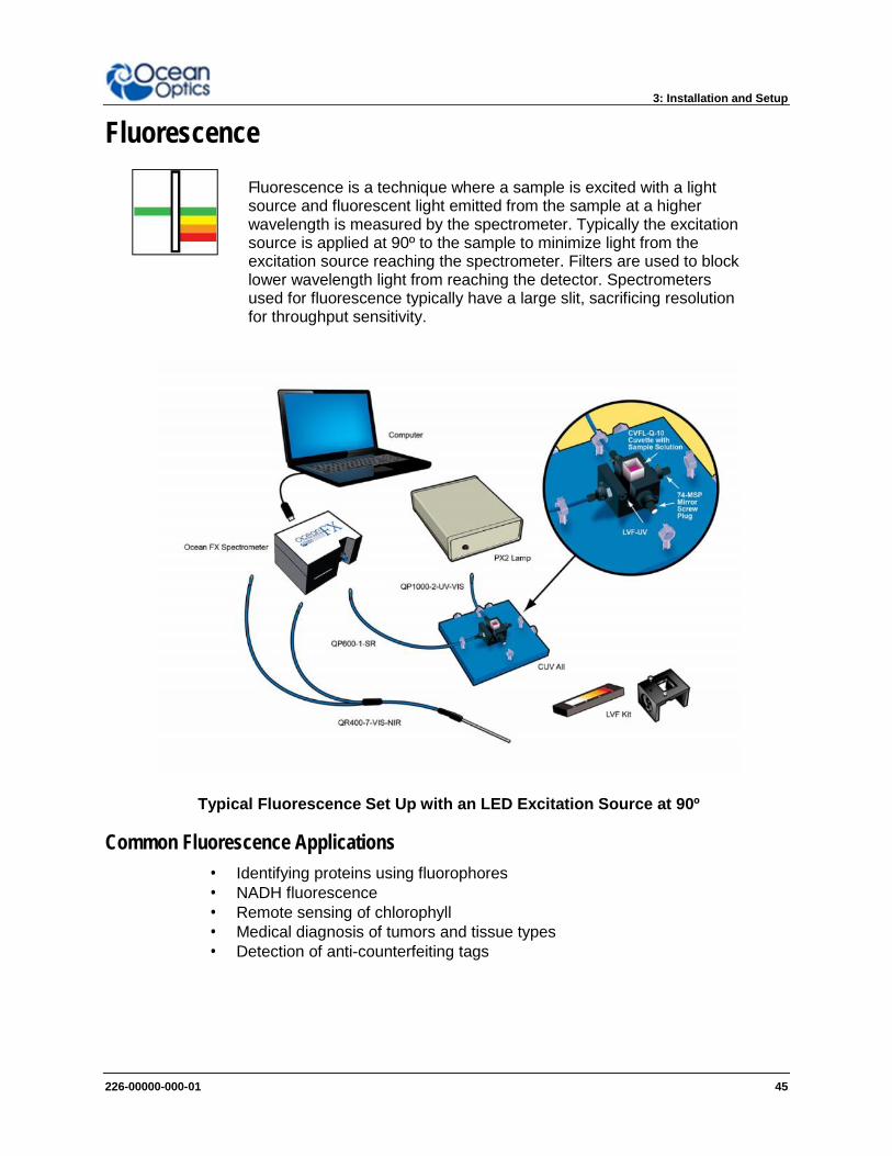
Typical Fluorescence Set Up with an LED Excitation Source at 90º
Common Fluorescence Applications Identifying proteins using fluorophores NADH fluorescence Remote sensing of chlorophyll Medical diagnosis of tumors and tissue types Detection of anti-counterfeiting tags
Fluorescence is a technique where a sample is excited with a lightsource and fluorescent light emitted from the sample at a higherwavelength is measured by the spectrometer. Typically the excitationsource is applied at 90º to the sample to minimize light from theexcitation source reaching the spectrometer. Filters are used to blocklower wavelength light from reaching the detector. Spectrometersused for fluorescence typically have a large slit, sacrificing resolutionfor throughput sensitivity.
3: Installation and Setup
226-00000-000-01 46
Irradiance
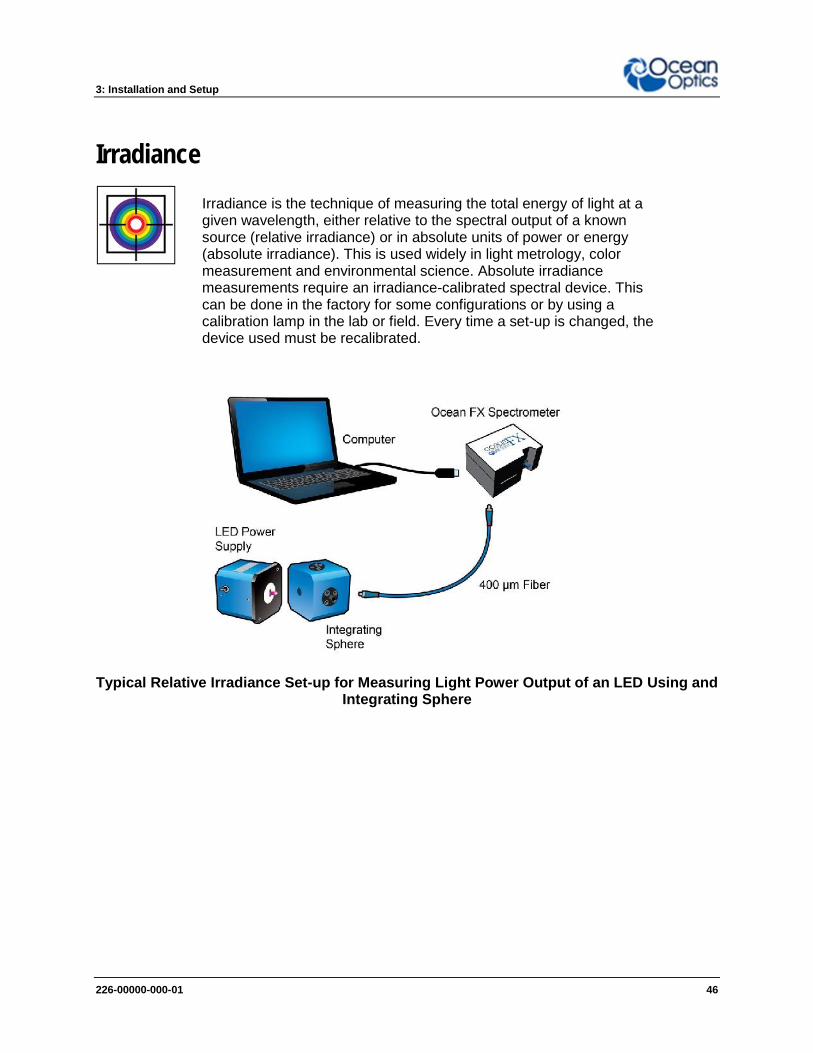
Typical Relative Irradiance Set-up for Measuring Light Power Output of an LED Using andIntegrating Sphere
Irradiance is the technique of measuring the total energy of light at agiven wavelength, either relative to the spectral output of a knownsource (relative irradiance) or in absolute units of power or energy(absolute irradiance). This is used widely in light metrology, colormeasurement and environmental science. Absolute irradiancemeasurements require an irradiance-calibrated spectral device. Thiscan be done in the factory for some configurations or by using acalibration lamp in the lab or field. Every time a set-up is changed, thedevice used must be recalibrated.

3: Installation and Setup
226-00000-000-01 47
Typical Set-up for an Absolute Irradiance Measurement Using Field Calibration with aCalibrated Light Source
Common Irradiance Applications Measuring the radiant output of lamps and LEDs Measuring color using relative irradiance Measuring the color rendering index (CRI) Measuring UV exposure for health and safety

226-00000-000-01 48
Chapter 4
Ocean FX Operation withOceanView
OverviewThe following information enables you to perform the basics of acquiring and saving data withyour Ocean FX Spectrometer and OceanView software. More detailed information aboutOceanView is in the OceanView Manual.
Launch OceanViewOnce you have installed your software and connected your spectrometer, start OceanViewwhich will display the Welcome Screen.
The OceanView Welcome Screen (Version 1.6 and higher)
Quick View - Displays the spectrum in Quick View mode showing raw, unprocesseddata. This is uncorrected for instrument response vs. wavelength. Quick View shows youa live shot of what the Ocean FX is “seeing”. From Quick View you can launchapplication wizards or construct your own method.
Load a Saved Project - Loads a previously saved project. Click Restore Last Sessionto reload the schematic and views as they were when the software was last closed.
Spectroscopy Application Wizards – Use this function to set up a measurement usingsimple step-by-step wizards. A large range of applications are available.

4: Operation
226-00000-000-01 49
OceanView Main ScreenNo matter what route you take on start up, you will soon end up on the OceanView main screen.This is where you can set and view acquisitions, save data, load data and save projects.
1. Acquisition GroupWindow
Use to set acquisition parameters such as integration time.Controls the spectrometer acquisition.
2. Schematic View Schematic view graphically displays the flow of information fromthe spectrometer to the view. Use nodes to mathematically modifythe data to create processed measurements (methods).
3. View Display Display your data, view, save and display controls, as well as otherfeatures such as peak finder and quick dark & reference.
4. Global Controls Control all spectrometers synchronously, save projects, and start anew application wizard.
5. Saved Data Displays data saved in the active save file path. Preview data,store notes and load overlays directly to the active view. Click toopen.

4: Operation
226-00000-000-01 50
Connect the Ocean FX in OceanViewRefer to the Initial Configuration section for the initial steps for your new Ocean FXspectrometer. Once the initial configuration is done, follow the steps below for when youconnect your device.The Ocean FX should automatically appear when you start OceanView and should be acquiringwith the default acquisition parameters. If you do not see a signal or the Ocean FX icon on theschematic you may need to rescan for spectrometers.
► ProcedureTo rescan for attached devices,
1. Click on the Device Manager icon ( ).
2. Click Rescan. The spectrometer should automatically connect.

4: Operation
226-00000-000-01 51
Set Acquisition ParametersSet Acquisition parameters in the Acquisition Group Window to control the spectrometer. Thiswindow may be minimized when you first start OceanView. You can either expand or open anew window from the menu (Window | Acquisition Group). An active acquisition is required forthe Acquisition window to appear. Functions available to control in the Acquisition windowinclude the following:
Strobe/Lamp Enable (on/off) – Use this function to turn an attached light source onor off.
Integration Time – Sets the integration time, the time over which the detectorcaptures incident light. At the end of the integration time the accumulated signal is readfrom the detector by the electronics.
Scans to Average – Signal, especially at low levels, is often significantly impacted bynoise. Averaging several spectra together reduces the impact of noise and provides acleaner result. With the Ocean FX, averaging is done onboard which can significantlyreduce spectral transfer times to the PC.
Boxcar Width – Boxcar is a form of averaging across pixels. It applies a rolling averageto multiple adjacent pixels to help smooth the spectral response and reduce the impactof noise.
Dark Spectrum – A dark spectrum is the set of counts versus wavelength values for aspectrometer at a given integration time when no light is present. This spectrum is usedto correct for baseline offset and fixed pattern noise. A dark spectrum must be stored toenable nonlinearity correction.
Nonlinearity Correction (on/off) – Detectors do not have a completely linearresponse. As they approach saturation, typically their efficiency reduces.
Trigger Modes – Sets triggering mode. X-Axis – Sets units for the X-axis. Throughput – Burst Mode acquires spectra into the onboard buffer of the OceanFX at
the maximum acquisition rate of 4500 scans per second.
Controls that appear in this window depend on the spectrometer model. You can add andremove acquisition controls from this window in the Add/Remove Controls tab.
Burst ModeBurst Mode is used to acquire spectral data at the fastest rate possible with the OceanFX (asfast as 4500 scans per second). When Burst Mode is enabled, the user specified number ofspectra are acquired and written to the onboard buffer of the OceanFX. Once all the spectrahave been acquired, the data can be written to a file by OceanView.
4: Operation
226-00000-000-01 52
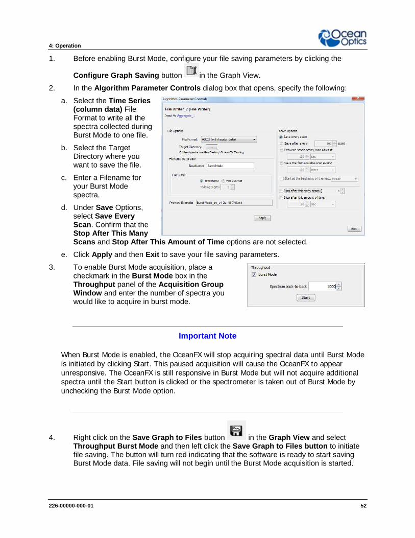
1. Before enabling Burst Mode, configure your file saving parameters by clicking the
Configure Graph Saving button in the Graph View.
2. In the Algorithm Parameter Controls dialog box that opens, specify the following:
a. Select the Time Series(column data) FileFormat to write all thespectra collected duringBurst Mode to one file.
b. Select the TargetDirectory where youwant to save the file.
c. Enter a Filename foryour Burst Modespectra.
d. Under Save Options,select Save EveryScan. Confirm that theStop After This ManyScans and Stop After This Amount of Time options are not selected.
e. Click Apply and then Exit to save your file saving parameters.
3. To enable Burst Mode acquisition, place acheckmark in the Burst Mode box in theThroughput panel of the Acquisition GroupWindow and enter the number of spectra youwould like to acquire in burst mode.
Important Note
When Burst Mode is enabled, the OceanFX will stop acquiring spectral data until Burst Modeis initiated by clicking Start. This paused acquisition will cause the OceanFX to appearunresponsive. The OceanFX is still responsive in Burst Mode but will not acquire additionalspectra until the Start button is clicked or the spectrometer is taken out of Burst Mode byunchecking the Burst Mode option.
4. Right click on the Save Graph to Files button in the Graph View and selectThroughput Burst Mode and then left click the Save Graph to Files button to initiatefile saving. The button will turn red indicating that the software is ready to start savingBurst Mode data. File saving will not begin until the Burst Mode acquisition is started.

4: Operation
226-00000-000-01 53
5. To start the Burst Mode acquisition, click the Start button in the Throughput panel ofthe Acquisition Group Window.
6. The message File Saving in Progress… will appear in the lower left corner of thesoftware window while files are saving. This message will continue to be displayed until
you click the Save Graph to Files button in the Graph View to stop Burst Modefile saving.
7. With Burst Mode file saving enabled, a new set of burst mode files will be appended toyour saved data file each time the Start button in the Throughput panel of theAcquisition Group Window is clicked.
8. To save each Burst Mode acquisition with a different filename:
a. Left click the Save Graph to Files button in the Graph View to stopsaving files in Burst Mode.
b. Click the Configure Graph Saving button in the Graph View to changeyour filename.
c. Click Apply and then Exit to save your new filename before you exit the dialogbox.
d. Left click the Save Graph to Files button in the Graph View to initiateBurst Mode file saving.
e. Click the Start button in the Throughput panel to save Burst Mode files to yournew filename.
9. To exit Burst Mode and return the spectrometer to free run mode:
a. Uncheck the Burst Mode box in the Throughput panel of the AcquisitionGroup Window
b. Left click the Save Graph to Files button in the Graph View to stopThroughput Burst Mode file saving
10. To preview your data in the Saved Data view, click on the file you want to preview andclick the Play button on the control menu.
4: Operation
226-00000-000-01 54
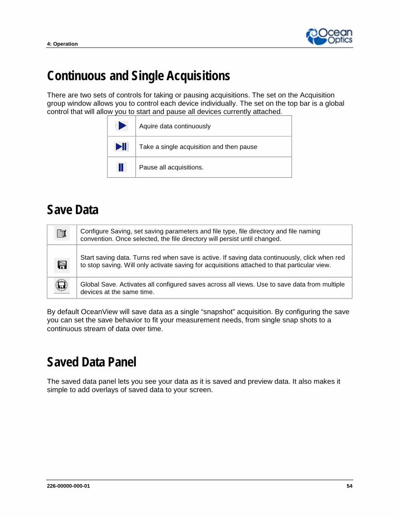
Continuous and Single AcquisitionsThere are two sets of controls for taking or pausing acquisitions. The set on the Acquisitiongroup window allows you to control each device individually. The set on the top bar is a globalcontrol that will allow you to start and pause all devices currently attached.
Aquire data continuously
Take a single acquisition and then pause
Pause all acquisitions.
Save DataConfigure Saving, set saving parameters and file type, file directory and file namingconvention. Once selected, the file directory will persist until changed.
Start saving data. Turns red when save is active. If saving data continuously, click when redto stop saving. Will only activate saving for acquisitions attached to that particular view.
Global Save. Activates all configured saves across all views. Use to save data from multipledevices at the same time.
By default OceanView will save data as a single “snapshot” acquisition. By configuring the saveyou can set the save behavior to fit your measurement needs, from single snap shots to acontinuous stream of data over time.
Saved Data PanelThe saved data panel lets you see your data as it is saved and preview data. It also makes itsimple to add overlays of saved data to your screen.

4: Operation
226-00000-000-01 55
Saved Data Panel
1. Saved Files List of saved files currently in the saved directory arranged by name or date.
2. Preview Shows a preview of the saved spectra, time series or appended series saved datacan be stepped through acquisition by acquisition using the controls above thesaved files list.
3. File Path Set the file directory.
4. Overlay Set the previewed spectra as an overlay on the active view.
5. Notes Enter notes about the saved spectra. Notes are saved with the same file name asa separate TSV file. These can be viewed or edited with any text viewer such asnotepad.
Projects and MethodsOceanView makes it easy to save and load projects and methods. We define a project as ameasurement set up made with a particular spectral device. If the software cannot find thedevice, it will load this as a method and prompt the user to select a substitute device from thoseselected.
Click to save a project. Alternatively select File | Save Project from the menu. Saves allview and schematic parameters to a single ASCII file.
Load a project or method.
4: Operation
226-00000-000-01 56
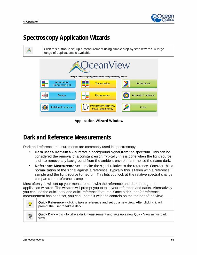
Spectroscopy Application WizardsClick this button to set up a measurement using simple step by step wizards. A largerange of applications is available.
Application Wizard Window
Dark and Reference MeasurementsDark and reference measurements are commonly used in spectroscopy.
Dark Measurements – subtract a background signal from the spectrum. This can beconsidered the removal of a constant error. Typically this is done when the light sourceis off to remove any background from the ambient environment, hence the name dark.
Reference Measurements – make the signal relative to the reference. Consider this anormalization of the signal against a reference. Typically this is taken with a referencesample and the light source turned on. This lets you look at the relative spectral changecompared to a reference sample.
Most often you will set up your measurement with the reference and dark through theapplication wizards. The wizards will prompt you to take your reference and darks. Alternativelyyou can use the quick dark and quick reference features. Once a dark and/or referencemeasurement has been set, you can update it with the controls on the top bar of the view.
Quick Reference – click to take a reference and set up a new view. After clicking it willprompt the user to take a dark.
Quick Dark – click to take a dark measurement and sets up a new Quick View minus darkview.
4: Operation
226-00000-000-01 57
Reference – click to update the stored reference measurement.
Dark – click to update the stored dark measurement.
Schematic View
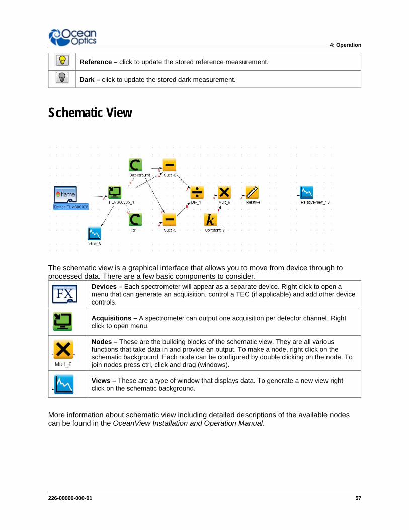
The schematic view is a graphical interface that allows you to move from device through toprocessed data. There are a few basic components to consider.
Devices – Each spectrometer will appear as a separate device. Right click to open amenu that can generate an acquisition, control a TEC (if applicable) and add other devicecontrols.
Acquisitions – A spectrometer can output one acquisition per detector channel. Rightclick to open menu.
Nodes – These are the building blocks of the schematic view. They are all variousfunctions that take data in and provide an output. To make a node, right click on theschematic background. Each node can be configured by double clicking on the node. Tojoin nodes press ctrl, click and drag (windows).
Views – These are a type of window that displays data. To generate a new view rightclick on the schematic background.
More information about schematic view including detailed descriptions of the available nodescan be found in the OceanView Installation and Operation Manual.

226-00000-000-01 58
Chapter 5
TroubleshootingOverviewSometimes things do not go to plan. If not, do not hesitate to contact us and our Tech Supportteam will leap into action. Some typical questions are answered here. For more information,consult the FAQs on the Ocean Optics website.
Frequently Asked QuestionsHow do I know my spectrometer has power?The red LED on the spectrometer should be on steadily if the unit is receiving power.
How do I know my spectrometer is transmitting data?The red LED on the spectrometer flashes when transmitting data.
How do I check the configuration of my spectrometer?Check the label on the bottom of your spectrometer. You can also check your configurationusing your spectrometer operating software. In OceanView, open the Schematic window anddouble click the spectrometer icon.
I am installing OceanView but I need a product key. Where can Ifind this?The product key was sent to the contact e-mail on the sales order when you purchased yourOceanView license. Contact [email protected] for more information. You’ll need your salesorder number, quotation number, the serial number of the spectrometer that was purchased withthe software, and, if known, the e-mail address under which your product key was created torecover your key.

5: Troubleshooting
226-00000-000-01 59
How do I determine whether my Windows computer is 32-bit or 64-bit?Errors can occur if you download the wrong version of software (32-bit or 64-bit). Go to theProperties or Settings window and find system settings.
I connected the USB cable and started OceanView but I do not seemy spectrometer attached.Use the Rescan button in the Device Manager to rescan for attached devices.
I am having trouble installing the drivers. What should I do?Hardware device driver installation is usually seamless on Microsoft Windows operatingsystems and should happen in the background when you connect your spectrometer to acomputer with the software installed. However, some Windows systems require a bit more carewhen connecting your spectrometer for the first time.If your spectrometer is not recognized by OceanView on your computer, you need to manuallyinstall the spectrometer drivers. See your OceanView manual for this procedure. Also consultthe Correcting Device Driver Issues document on the Ocean Optics website.

5: Troubleshooting
226-00000-000-01 60
I connected the Ocean FX to the computer before installing myspectroscopy operating software to install the drivers. What do Ido now?The steps to take to resolve this issue differ, depending on your computer’s operating system.
Microsoft Windows Operating Systems
Important Note
If these procedures do not correct your device driver problem, you must obtainthe Correcting Device Driver Issues document from the Ocean Optics website.
Remove the Unknown Device from Windows Device Manager
► Procedure1. Open Windows Device Manager. Consult the Windows operating instructions if needed.
2. Locate the Universal Serial Bus Devices option and expand the Universal Serial BusDevices selection by clicking on the "+" sign to the immediate left.
Important Note
Improperly installed USB devices can also appear under the Universal Serial BusController option. Be sure to check this location if you cannot locate the unknowndevice.
3. Locate the unknown device (marked with a large question mark). Right-click on theUnknown Device listing and select the Uninstall or Remove option.
4. Click the OK button to continue. A warning box appears confirming the removal of theUnknown Device. Click the OK button to confirm the device removal.
Disconnect the Ocean FX from your computer and then re-connect the spectrometer to yourcomputer. The system should now able to locate and install the correct drivers for the USBdevice.
Apple Mac OSX Operating SystemsSince there are no device files for the Ocean FX Spectrometer in a Mac operating system, youshould not encounter any problems if you installed the spectrometer before the spectrometeroperating software.
Linux Operating SystemsFor Linux operating systems, simply disconnect and then re-connect the USB cable in thespectrometer.

5: Troubleshooting
226-00000-000-01 61
I have both SpectraSuite and OceanView installed. Will myspectrometer work with both?Ocean FX only works with OceanView 1.6 and later.
I’m attempting to connect via Ethernet but I cannot see thespectrometer. What do I do?Connect the spectrometer to the computer utilizing the USB cable. Using OceanView, verify thefollowing:In Network Connections:
Interface 0 (network) is enabled. DHCP is enabled for Interface 0.
In Device Manager: See if device is displayed with an Ethernet connection/address. If not, rescan. If device is displayed but not connected, click the “connect” button.
I’m attempting to connect via WiFi, but I can’t see thespectrometer. What do I do?Initial setup must be done using the USB cable. If that has already been done, verify that thecomputer with OceanView resides on is on the same network and subnet as the spectrometer.Connect to the spectrometer utilizing the USB cable. Using OceanView, verify the following:In Network Connections:
Interface 1 (WiFi) is enabled. DHCP is enabled for Interface 1.
Security is set up with correct SSID and passphrase.In Device Manager:
See if device is displayed with a WiFi connection/address. If not, rescan. If device is displayed but not connected, click the “connect” button.
I configured my device via USB and am trying to connect to WiFi.Device manager shows the USB connection and then shows anerror message “Error while communicating with the device.Reconnect device and rescan devices.”Verify the device is properly connected to its power source. In Device Manager, unselect“automatically connect to devices”. Rescan. Once the device is displayed in the window, click“Connect” button. The device will appear. Reselect “Automatically Connect to Devices” option.

5: Troubleshooting
226-00000-000-01 62
Product Upgrades, Repairs and ServicingOccasionally, you may find that you need Ocean Optics to make a change or an upgrade toyour system. To facilitate these changes, you must first contact Customer Support and obtain aReturn Merchandise Authorization (RMA) number. Please contact Ocean Optics for specificinstructions when returning a product.
Firmware UpgradesProduct enhancements can be accomplished within firmware and the new firmware revisionscan be uploaded to the Ocean FX through OceanView. Below are upgrade instructions.
1. Go to the Ocean Optics website and download the two firmware files from theSoftware Downloads section. https://oceanoptics.com/support/software-downloads/
2. Connect your Ocean FX and open up OceanView (Version 1.6.3 or higher). Donot do this process wirelessly.
3. Go to the Schematic window and right click on the FX icon and click UpdateFirmware.
4. In the File Selection box, click the … button to locate an OBP file. Choose thelarger file.

5: Troubleshooting
226-00000-000-01 63
5. Once a file has been selected, click the Upgrade Firmware button.
6. Once complete, OceanView will ask to power-cycle the device. Power cycle thedevice and also close and restart OceanView.
Repeat steps 3 through 6 for the second file and then close OceanView, power-cyclethe Ocean FX and re-start OceanView.
RepairsSometimes accidents happen! If you need to return your Ocean Optics Product for repair, hereis what to do:
► Procedure1. Contact us to speak to an Ocean Optics representative about the problem. If it is determined
that the product must be returned, the representative will issue an RMA number.
2. Package your product, ideally in the original packaging, and return it to Ocean Optics, alongwith the RMA number that you received.
Important Note
For RMA returns under warranty we will organize and pay for shipping bothways. For accidental damage, you only pay to have the product delivered to yourclosest Ocean Optics or OOI Distributor Office.
Upon careful examination, we’ll advise you with an estimate. When your product is ready, it willbe returned to you.

5: Troubleshooting
226-00000-000-01 64
ServicingTo keep your instrument in tip top shape we recommend yearly wavelength recalibration.Contact your local representative to find out more about service availability and cost. We offerthe following services:
Wavelength Calibration Absolute Irradiance Calibrations

226-00000-000-01 65
Chapter 6
Technical Specifications
Mechanical Diagram
Ocean FX Outer Dimensions

6: Technical Specifications
226-00000-000-01 66
Absolute Maximum RatingsInput Voltage (Vin, VBatt, GPIO) 0 to +5.5V
Input Voltage (RS232) +/- 25V
Input Voltage (I2C, SPI, Other I/O) 0 to +3.6V
Table 10
Performance SpecificationsStorage Temperature -30°C to +70°C
Storage Humidity 0 to 90% RH non-condensing
Operating Temperature 0°C to +50°C
Operating Humidity 0 to 90% RH non-condensing
Recommended Frequency of Calibration The optical calibration should beperformed annually
Ethernet Gigabit transfer rate
USB 3.0, Type C connector Up to 5Gbps data rate
WiFi 802.11 a/b/g/n
Table 11

6: Technical Specifications
226-00000-000-01 67
Electrical CharacteristicsPARAMETER CONDITIONS MIN TYP MAX UNITSInput Current (Note 1) +5.0V, external power supply 0.9 2.5 A
Supply Voltage (Vin) 4.75 5.0 5.25 V
GPIO Logic Input Low 0.9 V
GPIO Logic Input High 2.4 V
GPIO ISOURCE / ISINK 1.6 mA
GPIO Output Low ISOURCE = 1 mA 0.4 V
GPIO Output High ISOURCE = 1 mA 3.1 V
GPIO DAC Resolution 12 Bits
GPIO DAC Output Range 0 5 V
I2C / SPI Logic Level I2C pullup resistor onboard 3.3 V
RS232 Output High 5.0 5.4 V
RS232 Output Low -5.0 -5.4 V
Other I/O Voltage Range 3.3 V
Table 12
Note 1: Maximum input current includes 1.0A for powering accessories through the DD4 connector. If no accessories are powered throughthis connector, then maximum input current drops to 1.5A.

6: Technical Specifications
226-00000-000-01 68
Optical and Spectroscopic CharacteristicsPARAMETER MIN TYP MAX UNITSDetector Response Range (note 2) 200 1100 nm
Integration Time 10 10E6 µs
Single Scan Dynamic Range 6423
System Dynamic Range (Note 3) 7.3E7
Single Scan Signal-to-Noise 290
Resolution (FWHM) (Note 4) 2.39 nm
Stray Light (Note 5) 1.9 a.u.
Max Scan Rate 4500 Scans
Buffer Depth 50000 Spectra
Thermal Stability 0.11 Pixels/°C
Trigger Jitter 21 ns
Table 13
Note 2: Spectral range for each spectrometer will be determined by specific features of the optical components.Note 3: Dynamic range of the system is the range of the detectable light level and can be thought of as the maximum detectable light level
at the minimum integration time divided by the minimum detectable light level at the maximum integration time.Note 4: Optical resolution of a spectrometer, measured as full width at half maximum (FWHM), depends on the groove density of the grating
and the diameter of the entrance optics (optical fiber or slit). A G01 600/300 grating and 5 µm slit is used for this measurement.Note 5: Stray light is reported here as the average of the stray light measured across 5 regions of the systems wavelength range.
Mechanical SpecificationsPARAMETER SPECIFICATIONSpectrometer Topology Asymmetric Crossed Czerny-Turner
Input Fiber Connector SMA 905 or FC/PC
Entrance Slit 5, 10, 25, 50, 100, or 200 µm slits. (Slits are optional. In the absence of aslit, the fiber acts as the entrance slit.)
Gratings Specifications vary by grating choice
Physical Dimensions 88.9 mm x 63.5 mm x 52.4 mm
Weight 0.4 kg (14.1 oz)
Mounting No restrictions on mounting. Can be mounted at any angle or position.
Table 14

6: Technical Specifications
226-00000-000-01 69
Accessory ConnectorsDD4 Accessory ConnectorThe Ocean FX features a 40-pin Accessory Connector, located on the front of the unit asshown:
Location of Accessory Connector
The Ocean FX features a 40-pin Accessory Connector (Part Number: DD4RA40JA1) that hastwo mating connectors available: DD4PA40MA1 (right angle) and DD4BA40WA1 (vertical).Pin 1 is on the right when viewing the 40-pin Accessory Connector from the front of thespectrometer. This connector is used to connect sampling and light sources to the Ocean FX.
DD4 Accessory Connector PinoutPIN# SIGNAL NAME VOLTAGE
LEVELDESCRIPTION
1 GND 0 System Ground2 IO_TRIG_EXT +3.3 Programmable Hardware Trigger3 IO_STROBE_CONT_EXT +3.3 Programmable Continuous Strobe4 IO_STROBE_SNGL_EXT +3.3 Programmable Single Strobe5 LAMP_EN +3.3 Programmable Discrete Output
DD4connector
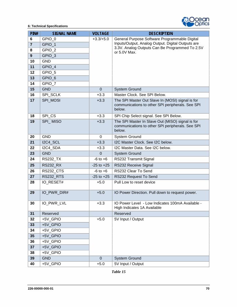
6: Technical Specifications
226-00000-000-01 70
PIN# SIGNAL NAME VOLTAGELEVEL
DESCRIPTION6 GPIO_0 +3.3/+5.0 General Purpose Software Programmable Digital
Inputs/Output, Analog Output. Digital Outputs are3.3V. Analog Outputs Can Be Programmed To 2.5Vor 5.0V Max.
7 GPIO_18 GPIO_29 GPIO_310 GND11 GPIO_412 GPIO_513 GPIO_614 GPIO_715 GND 0 System Ground16 SPI_SCLK +3.3 Master Clock. See SPI Below.17 SPI_MOSI +3.3 The SPI Master Out Slave In (MOSI) signal is for
communications to other SPI peripherals. See SPIbelow.
18 SPI_CS +3.3 SPI Chip Select signal. See SPI Below.19 SPI_ MISO +3.3 The SPI Master In Slave Out (MISO) signal is for
communications to other SPI peripherals. See SPIbelow.
20 GND 0 System Ground21 I2C4_SCL +3.3 I2C Master Clock. See I2C below.22 I2C4_SDA +3.3 I2C Master Data. See I2C below.23 GND 0 System Ground24 RS232_TX -6 to +6 RS232 Transmit Signal25 RS232_RX -25 to +25 RS232 Receive Signal26 RS232_CTS -6 to +6 RS232 Clear To Send27 RS232_RTS -25 to +25 RS232 Request To Send28 IO_RESET# +5.0 Pull Low to reset device
29 IO_PWR_DIR# +5.0 IO Power Direction. Pull down to request power.
30 IO_PWR_LVL +3.3 IO Power Level - Low Indicates 100mA Available -High Indicates 1A Available
31 Reserved Reserved32 +5V_GPIO +5.0 5V Input / Output33 +5V_GPIO34 +5V_GPIO35 +5V_GPIO36 +5V_GPIO37 +5V_GPIO38 +5V_GPIO39 GND 0 System Ground40 +5V_GPIO +5.0 5V Input / Output
Table 15

6: Technical Specifications
226-00000-000-01 71
SPIThe Ocean FX has the ability to function as a SPI master through the SPI port which comprisesthe SPI Master Clock, SPI Master MOSI, SPI Master CS and SPI Master MISO pins. To sendmessages over the SPI port, use the General SPI Input/Output message. The Ocean FX doesnot send or receive any SPI data without direction from the host device. Because SPI is a full-duplex transaction, the General SPI Input/Output message both reads and writes at the sametime. For instance, a four byte write will return four bytes of dummy read data, and a four byteread requires four bytes of dummy write data:
MOSI data is established just prior to the rising edge of the SPI clock
MISO data is sampled just after a falling edge of the SPI clock.
If using SPI as a master or slave, consult the Ocean FX Firmware and AdvancedCommunications document for more details. Consult with an Ocean Optics Sales Manager toobtain this document.
I2CThe Ocean FX has the ability to function as an I2C master through the I2C port, which includesthe I2C-SDA (data), and I2C-SCL (clock) pins. To send messages over the I2C port, use theGeneral I2C Write and General I2C Read messages. Note that the Ocean FX does not send orreceive any I2C data without direction from the host system. The I2C lines are pulled upinternally.
If using I2C communication, consult the Ocean FX Firmware and Advanced Communicationsdocument for more details. Consult with an Ocean Optics Sales Manager to obtain thisdocument.
DB15 Connector Cable (OCEAN FX-CBL-DD4P-DB15P)This cable connects the Ocean FX to existing Ocean Optics accessories that use a DB-15HDconnector. These include most light sources.
DD4 to DB15 Pin Connections15 PIN DD4 Name1 4 Single Strobe
2 3 Continuous Strobe

6: Technical Specifications
226-00000-000-01 72
3 40 Vusb
4 2 External Trigger In
5 2 External Trigger In
6 7 GPIO 1
7 NC Reserved (NC)
8 2 External Trigger In
9 8 GPIO 2
10 1 Ground
11 22 I2C SDA
12 21 I2C SCL
13 5 Lamp Enable
14 NC Reserved (NC)
15 11 GPIO 4
Table 16
226-00000-000-01 73
Chapter 7
CalibrationOverviewThis chapter provides information for performing your own wavelength calibration and irradiancecalibration.
An EEPROM flash memory chip in each Ocean FX contains wavelength calibration coefficients,linearity coefficients, and a serial number unique to each individual spectrometer. Thespectrometer operating software application reads these values directly from the spectrometer,enabling the ability to “hot-swap” spectrometers between host devices without entering thespectrometer coefficients manually on each host device.
OceanView can be used to write calibration coefficients to the spectrometer and reload firmwareif the spectrometer becomes corrupted.
Wavelength CalibrationThis section describes how to calibrate the wavelength of your spectrometer. Though eachspectrometer is calibrated before it leaves Ocean Optics, the wavelength for all spectrometerswill drift slightly as a function of time and environmental conditions. See the TechnicalSpecifications for recommended calibration frequency.
About Wavelength CalibrationYou are going to be solving the following equation, which shows that the relationship betweenpixel number and wavelength is a third-order polynomial:
p = I + C1 p + C2 p2 + C3 p3
Where: = the wavelength of pixel p
I = the wavelength of pixel 0
C1 = the first coefficient (nm/pixel)

7: Calibration
226-00000-000-01 74
C2 = the second coefficient (nm/pixel2)
C3 = the third coefficient (nm/pixel3)
You will be calculating the value for I and the three Cs.
Calibrating the Spectrometer WavelengthPreparing for CalibrationTo recalibrate the wavelength of your spectrometer, you need the following components:
A light source capable of producing spectral lines
Important Note
Ocean Optics’ HG-1 Mercury-Argon lamp is ideal for recalibration. If you do nothave an HG-1, you need a light source that produces several (at least 4-6)spectral lines in the wavelength region of your spectrometer.
An Ocean FX spectrometer An optical fiber (for spectrometers without a built-in slit, a 50-m fiber works best) A spreadsheet program (Excel for example) or a calculator that performs third-order
linear regressions
Calibrating the Wavelength of the Spectrometer
► Procedure1. Place the spectrometer operating software into Quick View (Scope) mode and take a
spectrum of your light source. Adjust the integration time (or the A/D conversionfrequency) until there are several peaks on the screen that are not off-scale.
2. Move the cursor to one of the peaks and position the cursor so that it is at the point ofmaximum intensity.
3. Record the pixel number that is displayed in the status bar or legend (located beneaththe graph). Repeat this step for all peaks in your spectrum.
4. Use the spreadsheet program or calculator to create a table like the one shown in thefollowing figure. In the first column, place the exact or true wavelength of the spectrallines that you used.
In the second column of this worksheet, place the observed pixel number. In the thirdcolumn, calculate the pixel number squared, and in the fourth column, calculate the pixelnumber cubed.

7: Calibration
226-00000-000-01 75
True Wavelength (nm) Pixel # Pixel # 2 Pixel # 3 PredictedWavelength Difference
253.65296.73302.15313.16334.15365.02404.66407.78435.84546.07576.96579.07696.54706.72727.29738.40751.47
175296312342402490604613694
10221116112214911523159016271669
306258761697344116964161604240100364816375769481636
10444841245456125888422230812319529252810026471292785561
535937525934336303713284000168864964808117649000220348864230346397334255384
10674626481389928896141246784833146137713532642667401967900043068788834649101309
253.56296.72302.40313.02334.19365.05404.67407.78435.65546.13577.05579.01696.70706.62727.24738.53751.27
0.090.01-0.250.13-0.05-0.04-0.010.000.19-0.06-0.090.06-0.150.100.06-0.130.19
5. Use the spreadsheet or calculator to calculate the wavelength calibration coefficients. Inthe spreadsheet program, find the functions to perform linear regressions.
6. Select the true wavelength as the dependent variable (Y). Select the pixel number, pixelnumber squared, and the pixel number cubed as the independent variables (X). Afterexecuting the regression, you will obtain an output like the one shown below. Numbersof importance are noted.
Regression StatisticsMultiple R 0.999999831R Square 0.999999663 R SquaredAdjusted R Square 0.999999607Standard Error0.125540214Observations 22
Intercept
Coefficients Standard ErrorIntercept 190.473993 0.369047536 First coefficientX Variable 1 0.36263983 0.001684745X Variable 2-1.174416E-05 8.35279E-07X Variable 3-2.523787E-09 2.656608E-10 Second coefficient
Third coefficient
Independent
VariableDependentVariables
Values Computedfrom the Regression
Output

7: Calibration
226-00000-000-01 76
7. Record the Intercept, as well as the First, Second, and Third Coefficients. Additionally,look at the value for R squared. It should be very close to 1. If not, you have most likelyassigned one of your wavelengths incorrectly.
Keep these values at hand.
Saving the New Calibration Coefficients: OceanViewOcean Optics programs wavelength calibration coefficients unique to each Ocean FX onto anEEPROM memory chip in the Ocean FX.You can overwrite old calibration coefficients on the EEPROM if you are communicating with theOcean FX via OceanView. Extreme caution must be used when performing this step. ContactOcean Optics for assistance and the necessary password to perform this function inOceanView.
► Procedure1. Ensure the Ocean FX device is properly connected.
2. Select the “Acquisition Group Window” -> “Add/Remove Controls” - > “WavelengthCoefficients”.
3. Enter password provided by Ocean Optics.
4. Follow the instructions provided by Ocean Optics.
Irradiance CalibrationsIrradiance calibrations and relative irradiance calibrations are about quantifying the spectra, bytranslating the signal to a calibration. This can be either absolute (an atomic emission lightsource of known output power) or relative (corrected for instrument response function but notabsolute units). It can be considered a measurement technique and is used widely in remotesensing, light metrology and anywhere where you wish to characterize the incident light source.Irradiance calibrations are not required for many techniques because these measure the relativesignal changes with respect to the sample and not the light source.OceanView has wizards that will step you through absolute irradiance and relative calibrationsand more information on these is in the OceanView manual.