ocean engineering summer laboratory 1975
TRANSCRIPT

OCEAN ENGINEERING SUMMER LABORATORY 1975
Massachusetts Institute of Technology
and
Maine Maritime Academy
Prepared by students under the
supervision of:
Professor A. Douglas Carmichael -- M,I.T.
M.M.A.
Report No. NITSG 76-3
Index No. 76-103-Nos
Professor David B. Wyman
NAf/0NAL SEA GRaNT KmlTDN'PELL L1BRARY BUIN!NQ
UPI, NARRAGP,I'ISETT BAY CAMPUSNARRAGANSETT, Rl 02882

MASSACHUSETTS INSTITUTE OF TECHNQI OGYSea Grant Program
Administrative Statement
The Ocean Engineering Summer Laboratory provides students fromthe Massachusetts Institute of Technology and from the Maine MaritimeAcademy with the opportunity to apply classroom knowledge to the actualdesigning, building, and testing of equipment for use in the ocean environ-ment. This report describes student work completed during the summerof 1975. The continued development of the computer-controlled robotsubmarine was a major focus of this year's summer laboratory. Otherprojects, including the construction of a pedal vehicle for SCUBA divers,of a windmill-power ed generator attached to a buoy, and of a floatingbreakwater, and the testing of cable strumming during tidal cycles, alsodemonstrate the positive benefits of students' experiences in solving"real-world" ocean engineering problems.
Dean A. Horn
Acting Director
April 1976
Roam 1-211 77 Massachusetts Avenue Cambridge, Massachusetts 02139 617 /253-7041

ACKNOWLEDGMENTS
Funding for the 1975 Surrrmer Ocean Engineering Laboratory was
provided by:
Office of National Sea Grant, Grant No. 04-5-158-1
Dr. Buckminster Fuller, Breakwater Project
Office of Naval Research, Cable StrummingExperiment
Maine Maritime Academy
Massachusetts Institute of Technology
Undergraduate Research Opportunities Prograrrr,Massachusetts Institute of Technology
Clapp and Poliak Scholarships,Massachusetts Institute of Technology
The memory chips for the robot computerwere kindly supplied by the IntelCorporation of Santa Clara, California

Massachusetts Institute of Technolo
Debra G. AbbottBruce C. Amero
William BurkeStephen W. Carle
Miles R. FidelmanBrad L. Collins
Thomas Darlington
Harvey K. DunningWerner H. Haag
Robert Ethxer!ttai Kan
Marek Klonowski
Philip Kramer
John C. Newman
Michael J. Saylor
William F Whitelaw
Jim MalloyGraduates:
Thomas ManginoStuart D. Jessup
Henry Martin
Peter Scanlon
Glenn J. Keller
Charles H. Mazel
ROger A. Longhorn Fall & Spring terms!
Joseph M. Driear Fall & Spring terms!
Norman Oliver Fall term!
George Rodenbush Part time!
Gordon Williams
Donald Wyman
Raymond J Yak
Charles L. Finkelstein
LIST OF PARTICIPANTS
Maine Maritime Academy
Christopher W. Fay
Kevin Fitzpatrick
Robert Gehring
John Jacoby
John Leonard
Michael McGuckin

Faculty:
P. Douglas Carmichael
J. Kim Vandiver
Faculty:
David B. Wyman
Donald A. Small
Groves E. Herrick
E Biggie

'TABLE OF CONTENTS
Page
ADMINISTRATIVE STATEMENT
ACKNOWIEDGMENTS
LIST OF PARTICIPANTS
TABLE OF CONTENTS
SUMMARY
PREFACE
V3.
1X
THE UNDERCYCLE
THE SUBMARINE ROBOT
THE HULL AND PROPULSION SYSTEM
THE ROBOT ELECTRONICS
THE ROBOT EMERGENCY SYSTEMS
THE ROBOT TEST PROGRAM
A WINDMILL POWERED BUOY
CABLE STRUMMING EXPERIMENTS
A PORTABLE FLOATING BREAKWATER
2.
3.
4.
5.37
416.
7.47
8.
789.
10. 83PRELIMINARY SONAR AND MAGNETOMETER SURVEY FOR VESSELSDESTROYED IN THE PENOBSCOT EXPEDITION OF 1779
SUMMARy
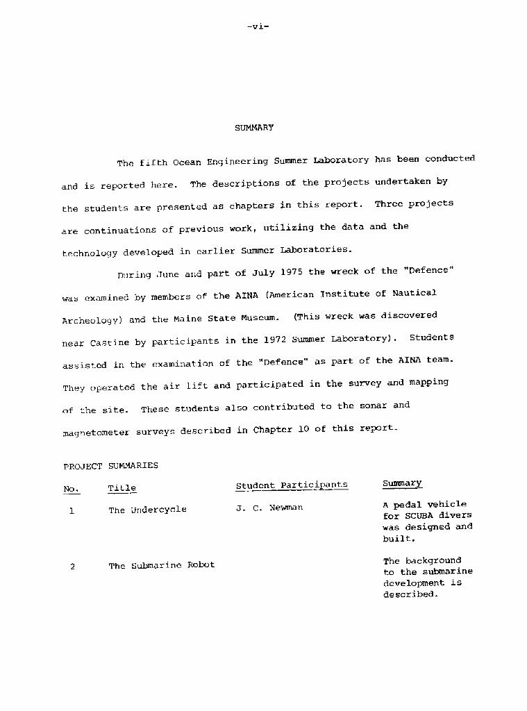
The fifth Ocean Engineering Summer Laboratory has been conducted
of the site. These students also contributed to the sonar and
magnetometer surveys described in Chapter 10 of this report.
PROJECT SUMMARIES
Student Partici antsTitleSummary
No.
A pedal vehiclefor SCUBA divers
was designed andbui 1 t.
The Undercycle J. C. Newman
The Submarine Robot The backgroundto the submarinedevelopment isdescribed.
and is reported here The descriptions of the projects undertaken by
the students are presented as chapters in this report. Three projects
are continuations of previous work, utilizing the data and the
technology developed in earlier Summer Laboratories.
During June and part of July 1975 the wreck of the "Defence"
was examined by members of the AINA American Institute of Nautical
Archeology! and the Maine State Museum. This wreck was discovered
near Castine by participant in the 1972 Summer Laboratory!. Students
assisted in the examination of the "Defence" as part of the AINA team.
They operated the air lift and participated in the survey and mapping

Title
P. Kramer
W. BurkeThe Robot
Electronic s
W. H. Haag
P. Kramer
W. Burke
P. Kramer
W. Whitelaw
C. W. Fay
The Hull and
Propulsion System
The Robot
Emergency System
The Robot Test
Program
A Windrnill Powered
Buoy
Student Partici nts
D. G. Abbot t
M. Klonowski
S. D. Je s sup
N. R. Fidelman
C. L. Finkelstein
M. J. Saylor
G. J. Keller
J. M. Dri ear
R. A. Longhorn
W. F. Whitelaw
D. G. Abbot t
C. L. F inkel stein
M. Klonowski
The design, fabricationand operation of thehull and mechanicalsystems in thevehicle are described.
The design anddevelopment of thecomputer and autopilotare described. The
computer softwareand operating programsare also discussed.
The recovery of thevehicle in the event
of possiblemalfunctions isdiscussed.
The operationaldevelopment of thevehicle leading tothe measurement
and recording ofwater temperatures
is described.
The design,construction andoperation of awindmill poweredgenerator attachedto a buoy are presented.
Title~Summar
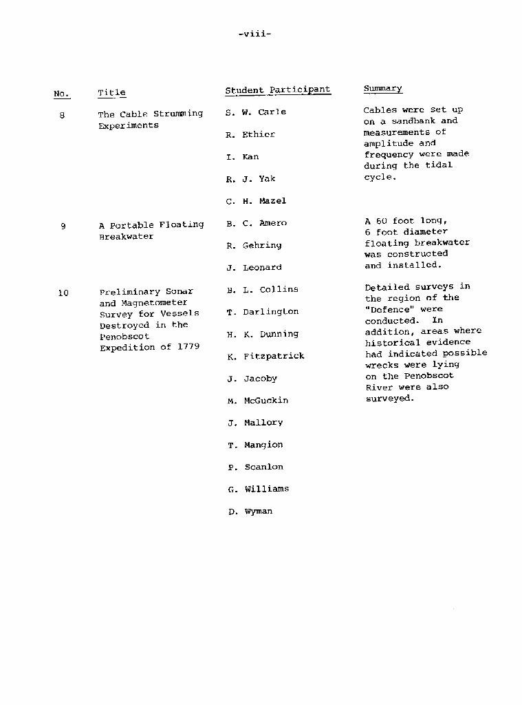
S. W. Carle
R. Ethier
I. Kan
R. J. Yak
C. H. Mazel
B. C. Amero
R Gehring
J' Leonard
M. McGuckin
J. Mallory
T. Mangion
P. Scanlon
G. Williams
The Cable StrummingExperiments
A Portable Floating
Breakwater
Preliminary Sonar
and MagnetometerSurvey for VesselsDestroyed in thePenobscot
Expedition of 1779
Student Partici ant
B. L. Collins
T Darlington
H. K. Dunn ing
K. Fitzpatrick
J. Jacoby
Cables were set up
on a sandbank and
measurements of
amplitude andfrequency were madeduring the tidalcycle.
A 60 foot long,
6 foot diameter
floating breakwaterwas constructedand installed.
Detailed surveys inthe region of the"Defence" were
conducted. In
addition, areas wherehistorical evidencehad indicated possiblewrecks were lyingon the Penobscot
River were also
surveyed.

PREFACE
The Ocean Engineering Laboratory provides the opportunity
for undergraduate students to design and build equipment for use in
the oceans, and then to test the devices produced. This is the main
objective of the laboratory. The relative inexperience of the
students in engineering design and the time and other constraints
results in equipment which not always operates successfully despite
the energy and ingenuity of the students. On the other hand, modest
successes are achieved at times and the pleasure that such successes
provide is encouraging to observe.
The ten chapters of this report do not adequately convey the
whole experience. Meetings were held in the evenings to describe
the various projects and to present technical movies of interest.
About half the students participated as divers and carried
out diving projects. A group of students also built and tested diverpropulsion units constructed using commercial plans. The safety officerfor the diving program was Professor Edgar Biggie of the Maine Maritime
Academy.
Many distinguished viSitors came to see the summer program in
operation, and Dr. Harold Edgerton and Martin Maylach brought survey
instruments which were used in the search for archaelogical sites.
These efforts are described in Chapter 10 of this report.
1. THE UNDERCYCLE
The scuba diver with his rubber fins is capable of modest
performance and maneuverability under the oceans. It was felt that the
divers range of operation and his speed could be improved by providing
him with a lightweight pedal vehicle that he could use for underwater
transportation. The design, development and early testing of such a
vehicle is described herc'
PRELIMINARY CONSIDERATIONS
The major question is whether the power developed by such a
system would be sufficient to propel a man underwater at a useful speed.
Previous research and experimentation has resulted in the following
relationship for the drag of a diver:
2Drag = 4 v
Drag is measured in pounds and velocity in knots. While a well conditioned
human can develop as much as one horsepower with his legs for a short
time, a more conservative figure of one tenth of one horsepower is
sufficient to propel a diver at a speed of one and a half knots. For a
brief period of time, a diver might be expected to reach speeds as high
as three knots.
While a cyclist has little difficulty in keeping up a cadence
of sixty to seventy revolutions per minute, it was thought. that this might
be difficult underwater, as the movement af the legs would introduce
additional drag. While much of this problem can be solved by choosing

FIGURF. l.l The Undercycle

the proper gear ratios and a slower cadence, it is clear that a relatively
slow rpm of the propeller is an inherant part of an underwater man powered
vehicle. It was very important, therefore, that as large a propeller
as feasible be chosen, and that the rest of the craft be designed
around its characteristics. The propeller chosen is a three bladed,
fiberqlass propeller, slightly over eighteen inches in diameter. The
pitch to diameter ratio was measured to be roughly l.l. From these
characteristics the ideal revolution speed of the propeller was determined
to be one hundred and fifty five rpm, yielding an excellent efficiency of
0 65.
1.2 DESIGN AND CONSTRUCTION
The major pieces of design work were the basic frame of the
vehicle, the control surfaces, and the drive mechanism. The original
design of the frame called for a tubular aluminum A frame structure. This
design was changed to a rectangular shape in order to facilitate
construction and mounting of the control surfaces, as shown in Figure 1.1.
One and a half inch inside diameter! PVC pipe and pipe fittings were used
to construct the frame. The overall length of the craft is slightly
under seven feet while it is about two feet wide. Mounted at waist
level on the frame is a twelve inch plywood disc. The frame of the under-
cycle is free flooding, and since PVC has a specific gravity of about
1.2, the frame itself is negatively buoyant. At present, through the
use of flotation material inside the frame the buoyancy of the overall
craft is only slightly negative. The bow floats a bit higher than the
stern, this having been found a convenient way to ride.

The control surfaces of the undercycle consist of two,
individually operated front diving planes. Each of these planes has
an aspect ratio of approximately one and a surface area of two square
feet. Surrounding the propeller is an eight inch band of aluminum,
which besides guarding the propeller serves effectively as a
stabilizer. There is no rudder on the craft, steering is accomplished
by raising or 3.owering! the diving planes to different angles, The
vehicle rolls into turns in much the same manner that an airplane does.
Assuming a total mass of diver, equipment, and undercylce, of three
hundred pounds, the vehicle has a calculated turning radius of twenty
nine feet. At cruising speed the time needed to complete a ninety
degree turn would be eighteen seconds.
The most, difficult design problem is the drive mechanism, or
more specifically, the gearbox. The pedals equipped with toe clips to
keep one's feet from floating off, are attached to regular bicycle
crank arms. These are attached to the brass axle shaft, which passes
through the gearbox and carries a bevel gear. The propeller shaft
protrudes from the gearbox in the rear, and runs to the stern inside
the center pipe of the frame.
The gearbox is a four inch long section of six inch diameter
pvc pipe. The axle shaft is centered in the endcaps of the gearbox.
Designed with a watertight seal, the shaft is seated in noncorroding
Teflon flange bearings, with dynamic "0" rincs completing the seal. The
drive shaft is similarly designed, The gears consist of a four inch
diameter, cast iron bevel gear and a smaller hardened steel pinion.
These gears, while well greased, should ideally have a protective coat

to eliminate corrosion. The bevel gear has sixty four teeth while the
pinion has sixteen, yielding a four-to-one ratio. Thus, in order to
rotate the propeller at the optimal rate of one hundred and fifty five
rpm the rider must pedal at a rate of under forty rpm.
THE TESTIHG PROGRAM1.3
The initial tests of the craft were to accomplish little more
than determining the necessary ballasting and proper placement of the
control surfaces. Eventually the buoyancy of the craft was adjusted to
be slightly negative with the stern more so, to make riding near the
surface possible without the propeller breaking the surface. The initial
placement of the front planes was found to be satisfactory. Holes were
drilled through the frame to allow for the handlebars.
The actual period of testing resulted in failures by several
different parts of the craft. The original pedal crank arms, machined
from PVC were not strong enough to resist the shearing force applied to
them by pedaling. Several pins were also replaced with quarter inch
diameter hardened steel cotter pins, as even easy pedaling developed
very large forces and torque. The seal on the drive shaft at the rear
of the gearbox proved defective which allowed the gearbox to flood.
Besides greatly increasing the rate of corrosion of the gears this
causes a great loss of buoyancy, nearly twenty pounds
While all of the above failures were repaired or allowed for
by modifications in the design, the craft still suffered from one problem.The transverse thrust. of the propeller causes the entire craft to roll.
This can be prevented by tipping up the opposite diving plane. However,

a. The Undercyc1e on the Beach
b. The Vehicle in Operation
FIGURE 1.2 The Undercycle

this results in many difficulties in maneuvering. The solution to this
problem would be a weighted keel of perhaps twenty pounds placed below
the rider.
CONCLUSIONS AND RECONKENDATXOHSl.4
While the problem of the torque caused by the transverse
thrust of the propeller unfortunately makes the undercycle somewhat
difficult to learn to ride, the vehicle must be considered a partial
success. It moves forward and backwards, and it turns and dives faster
and easier than expected. Consideration could be given to sealing
the frame as well as the gearbox. The tubes of the frame could be
equipped with valves making the trim adjustable. While the vehicle
is not easy to carry by oneself, it is not more difficult than a
surfboard. The undercycle can carry much more gear than a diver can
while swimming, and as the pedals turn almost effortlessly, it is a
great deal more fun.

2. THE SUBMARINE ROBOT
SUMMARY2.1
BACKGROUND2. 2
The design, construction and development of a computer
controlled robot capable of making continuous measurements of
temperature, salinity, and turbidity during controlled missions was
considered to be a useful project for students of the summer laboratory.
The specification for the vehicle was as follows:
Design Speed 3 knots
20 miles at 3 knots!
200 ft.
Maximum Range
Maximum Depth
Maximum Height
Instrument Payload
250 lb. in air
50 lb.
The design of the robot and its construction was completed for
the 1974 Summer Laboratory. There were some shortcomings with the
original design and it was not operated successfully under its own
control in 1974. The method of operating the control surfaces rudder
and driving planes! was unreliable and changes in the computer and
autopilot electronics were required. The development of the robot was
continued during 1975 and it eventually operated under computer control
with all systems working during the 1975 Summer Laboratory.


-10-
Using this basic specification a design of vehicle was evolved which has
proved to be satisfactory in every important aspect.
The robot is free flooding with all the critical components
enclosed in watertight PVC tubes The energy source is an automotive
lead-acid battery and the propulsion is by means of a propeller driven
by an electric motor through a reduction gearbox. A mini-computer
provides the control commands which are executed by an autopilot. The
computer memory can be used to store transducer and instrument outputs
in addition to the control programs.
-11-
3. THE HULL AHD PROPULSION SYSTEN
3.1 THE HULL
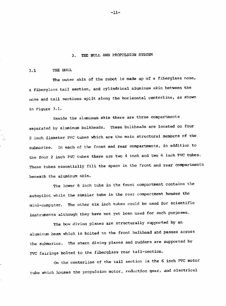
The outer skin of the robot is made up of a fiberglass nose,
a fiberglass tail section, and cylindrical aluminum skin between the
nose and tail sections split along t' he horizontal centerline, as shown
in Figure 3.1.
Inside the aluminum skin there are three compartments
separated by aluminum bulkheads. These bulkheads are located on four
2 inch diameter PVC tubes which are the main structural members of the
submarine. In each of the front and rear compartments, in addition to
the four 2 inch PVC tubes there are two 4 inch and two 6 inch PVC tubes.
These tubes essentially fill the space in the front and rear compartments
beneath the aluminum skin.
The lower 6 inch tube in the front compartment contains the
autopilot while the similar tube in the rear compartment houses the
mini-computer. The other six inch tubes could be used for scientific
instruments although they have not yet been used for such purposes.
The bow diving planes are structurally supported by an
aluminum beam which is bolted to the front bulkhead and passes across
the submarine. The stern diving planes and rudders are supported by
PVC fairings bolted to the fiberglass rear tail-section.
On the centerline of the tail section is the 6 inch PVC motor
tube which houses the propulsion motor, reduction gear, and electrical

-l2-
I
0
C
0 0
0
0 8P R
< PW 0 S

-13-
filter circuits and relays. In addition the servomotors for the rear
diving planes and rudders are placed in the motor tube.
The space inside the nose fairing is largely available for
instrument packages. The only components in the nose are a small
sensor package, a short length of 2 inch PVC tubing housing the front
servomotor, and a small container for lead shot, used to trim the
submarine.
3.2 TEE PROPULSION SYSTEM
The robot has a two bladed aluminum propeller 12 inches in
diameter driven through a 10:1 reduction gearbox by a 12 volt dc motor.
The energy is supplied by an automotive lead acid battery modified for
immersion in seawater.
3.2. 1 The Pro ulsion Train
The electric motor was obtained from an electric outboard
motor system. The motor characteristics were determined by a brake
test and matched to the measured propeller characteristics and predicted
drag of robot by the reduction gearbox. It was predicted that a 10:1
reduction gear ratio would be appropriate as it would match the motor
and propeller close to their respective maximum efficiency levels.
The reduction gearbox was built from inexpensive stock gear-wheels
and bearings.
The shaft to the propeller passes through "0" ring seals in
the endcap of the motor tube as shown in Figure 3. 1. The propeller
is carried in bearings supported by an aluminum structure braced by
the motor tube. The propeller shaft between the motor tube endcap and
the propeller has a small coupling to allow for misalignment.

U
0 U 0 QlV!
0 0'U <P
0 0 0 Q.0C4
0 0U
0 0X

3.3 THE CONTROL SURFACES
Bow Divin Planes3. 3.1
The servomotor for the bow diving planes is housed in a short
length of 2 inch PVC tubing and attached to one endcap. The single
stage gear system giving reduction is fabricated into the endcap to
provide an axial output via a dynamic "0" seal. The endcap on the
other end of the servometer housing has the sealed electrical plug
to transmit the electrical signals to and from the the
servometer.
The control surfaces are actuated by a shaft which is placed
transversely on the centerline of the submarine. This shaft has small
cranks and connecting rods driven by the output shaft of the servomotor
tube�as shown on Figure 3. 2.
The diving planes have fixed sections, fabricated in PVC,
which protect and support the moving control surfaces. These fixed
sections also provide the outer bearings to align and allow movement
of the control surfaces. The inner bearings for each moving control
surface are flanged plastic bearings attached to aluminum strips which
are screwed to the aluminum skin. The use of slotted holes permits
accurate alignment of the bearings to facilitate free movement of the
control surfaces.
The bow and stern control surfaces are actuated by small
servomotors which have intergral position feedback potentiometers. These0
servomotors have a total angular travel of about 270 while the control0
surfaces were designed to have a range of + 30 . Small gear trains
are used to obtain the reduction.

-l6- 4-I0
IX~rM

-17-
The overall alignment and structural strength of the fixed
sections of the control surfaces is maintained by an aluminum beam of
right angle section which is placed transversely across the submarine
at the horizontal centerline and screwed to the forward bulkhead, as
described earlier. This aluminum beam was machined from a larger
channel section. During operation of the submarine the beam was twisted
by an unfortunate underwater collision during the early successful
operation of the robot. The beam was straightened and returned to
the submarine.
3.3.2 The Stern Control Surfaces
The servomotors for the stern diving planes and the rudders
are placed in the motor tube. The diving planes have one servomotor
each which track together while the two rudders are driven by a single
servomotor. The outputs of the servomotors are taken through dynamic
"0" ring seals in the aluminum endcap of the motor tube. On the
outside of the endcap there are 4:1 bevel reduction gears which
transmit the drive to the control surfaces, as shown on Figure 3.3. The
bevel reduction gears are fabricated from stainless steel components.
The drive to the top rudder is directly from the bevel gear
while the bottom rudder is driven by a yoke which permits the drive
to cross the propeller shaft, as shown on Figure 3.3
The stern controls surfaces, like the bow planes, have fixed
sections and actuated sections. The fixed sections of the control
surfaces were fabricated in PVC and bolted to the fiberglass tail cone.
The moveable control surfaces are supported in bearings machined in the
PVC.

� 18-
F'lutter Valve
Switch
PICTURE 3.4 Battery Cover and Vent System

-19-
3.4 THE COMPENSATED BATTERY
The battery supplying the electrical power for the robot is
a 96 ampere-hour automotive battery, modified to allow it to be immersed
in sea water. The battery system has remained one of the more
troublesome problems with the robot. The difficulties are associated
with the pressure compensation of the battery and the continual
production of hydrogen in lead-acid batteries. In order to maintain
the battery at the local ambient pressure it is necessary to fill the
space above the electrolyte with oil and to transmit the pressure to
the oil by means of a rubber container. The hydrogen produced must be
vented to environment while the oil must be retained. Partial success
was achieved by building a special top for the battery to contain the
oil and to vent the gas, Figure 3.4. In the vent valve an attempt
was made to discriminate between oil and gas. The valve contains a
float and rubber flutter valve. As gas is produced at the plates of
the battery it displaces oil above it as it rises. The float then
rises and closes the valve. When the gas has risen to the valve it
allows the float to fall and when the gas pressure has risen sufficiently
to open the flutter valve the gas blows off. This valve system has
been found to reduce the outflow of oil although it has not completely
eliminated the problem.

-20-
a. Viewed With Tail Cone Removed, Showing Computer Tube andInternal Arrangement
b. With Top Skin Removed With Showing Control Panel
FIGURE 3.5 The Robot Submarine

-21-
4. THE ROBOT KLECTRONXCS
The purpose of the electronic system for the robot is to
control all the functions of the robot. These functions include the
testing, checkout, and programming of the robot before an operation
and also the control and navigation of the vehicle when underway.
The main components of the electronics system are the computer, the
interfaces, and the autopilot.
Before each operation the computer programs required to
control the submarine are transmitted to the computer memory from a
paper tape reader or magnetic tape recorder. Immediately prior to
the mission the operation of the servomotors, propulsion motor,
sensors, and any instrumentation are checked-out manually by means
of a control box on the dock. This box is coupled to the various
components by the interface. On completion of the check-out any final
instructions for the operation are sent to the computer by the control
box via the interface and the computer is set to run. After a suitable
pause to allow the control box to be disconnected and the robot to bereleased, the computer then instructs the propulsion motor to start,
the autopilot to set the desired depth and the desired course, and
scientific measurements tobe made and recorded in memory. After the
prescribed time has elapsed the computer instructs the autopilot tochange course and depth and eventually to stop. The robot is returned

� 22-
to the dock where new instructions would be transmitted to the computer.
EVentually, at the end Of OperatianS, the inStrumentatiOn data are
retrieved from memory and printed out or put onto paper tape for
transcription and analysis.
4 THE COMPUTER
The architecture of the computer is similar to l2 bit PDP
8 series Digital Ecuipment Corporation!. However, the 16 bit wide
data paths give it some capabilities of the Nova series Data General
Corporation!. Due to the requirement of low power consumption in the
robot, the computer is much slower than the Nova. Typical instructions
are 2l microseconds ps! compared with l.5 ps for the Nova, however, the
total power consumption of the computer is only 3. 5 watts.
In parallel with the construction of the computer hardware
has been the development of the software to make the programming easier.
The availability of this software has enabled several subroutines to
be developed which permit the control of the robot.
The robot computer, in common with most computers, has three
main parts:
l. A central processing unit which executes instructions.
2. A memory unit, which stores data and instructions forprocessing.
3. Input/output interfaces which exchange informationbetween the computer and its environment.
These three units are mainly housed on separate circuit boards in the
lower stern 6 inch PVC tube, although a large section of the interface
is in the autopilot tube.

-23-
4.1.1 The Central Processin Unit CPU!
The purpose of the CPU is to execute the instruction coded
in a 16 bit digital form. These instructions are of three types:
l. Input/output, for communication with the interfaces.
2. Memory reference, arithmetic and program controloperations to the memory.
3. Accumulator, operations upon a special register whichcan change the program flow depending on its contents.
The circuits that execute the instruction are of three
types:
1. Control Logic
2. Data Paths
3. Registers
The control logic circuits adjust the data paths so that the
data flows between register and to-and � from the memory and the various
interfaces. The data paths consist mainly of mulitplexers and
transmission gates through which the data flows. The registers have
many purposes but they are essentially temporary stores for data and
instructions.
4.1.2 The Computer Memory
It is described as a 4K 16 bit memory as it has 4096 locations
and each location can contain 16 bits of information. The memory
hardware includes the sixteen 4K by one bit memory chips together with
clock drivers, logic chips and transistors for changing the voltage
level to that of the memory �-5 volts! from the level in the rest of
the computer �-10 volts!.

-24-
The Interfaces4.1.3
to and from them and because they have different modes of operation.
Serial transmission of data and multiplexing are used to reduce the
numbers of interconnecting wires between the computer and the interfaces.
Serial transmission involves moving data along a single wire one bit at
a time. Nultiplexing allows a single wire to be used for various
functions.
2'he submarine interface:
The main purpose of the submarine interface is to send
commands to the autopilot and the controllers and to receive data back.
Since the computer operates with binary numbers while the rest of the
submarine utilizes mainly analog voltage levels, an important function
of the interface is to convert to and from these different systems.
There are digital-to-analog converters D ~ A! to change the digital
number coming from the computer into voltage levels between 2.25 volts
and 7.75 volts as used by autopilot and controller. Voltage outputs
from the autopilot are changed to binary numbers in the analog to
digital converter A ~ D! and then transmitted to the computer.
The internal interface in the submarine connect the computer
to the autopilot and to the servo-amplifiers. The external interfaces
allow the computer to be connected to the control panel, the teletype,
and the tape recorder. These internal and external devices require
different interfaces because of the various forms of the data transmitted

-25-
The computer can transmit three types of instructions to the
submarine interface:
l. An order, which can set the depth command, coursecoo@md, and control the motor.
2. A direct coned, which can directly control theservomotors coupled to the control surfaces.
3. A readout instruction, which transmits informationback to the computer from the autopilot.
The first two bits in the l6 bit instruction define which of the three
types of commands is required. Bits 2-7 define the device instructed e.g. bow diving plane, or depth required!, while bits 8-15 containany digital data conveyed by an order or direct, command. The interface
is called upon to interpret the instructions from the computer, to
select the correct gath to carry out the command, convert the form of
the data if necessary, and then to pass the instruction to the device.
2'he eztewnaK interface.
These interfaces are all different since they involve
interfacing the robot computer with the control panel, the teletype,
and the tape recorder.
The control panel has 16 data switches, 16 function switches
and a 16 bit data display using light emitting diodes. The main purpose
of the control panel is to send the instructions to check-out all
the main systems in the robot before a mission and to send the finalinformation for a particular mission. In addition, when turning the
computer on it is necessary to send a short instruction program termedthe bootstrap loader! in order to enable the computer to accept programs
from the teletype, papertape, or tape recorder.

-26-
The data from the control panel is sent by serial transmission
and the function and data signals to the computer are multiplexed. In
this way the total number of wires from the panel to the computer is
reduced to five. In addition to the send. line, there is a return line,
a clock line, an "end of transmission" line, and common.
The teletype interface has been designed to allow two-way
communication between the computer and the teletype or between the tape
recorder and the computer It has been arranged to make the recorder
look like a very fast teletype. The information is transmitted between
the computer and teletype in serial form and requires four wires and
common,
4. l. 4 Com uter Sof tware
The robot computer, like other computers, is essentially a
device capable of storing and manipulating inforroation presented in
binary form. This is termed machine language. Both the data and the
instructions to manipulate the data are in this confusing binary format.
The programmer can simplify his program writing procedure by changing
from binary to octal numbers which reduces the 16 bit binary
repreSentatiOn tO OCtal numberS frOm 0 � 177777. A further SimplifiCatian
to assist the programmer is to devise a letter code to represent
operational steps. These codes are more-or-less! standard for small
computers and the instructions are termed the assembly language. As
an example, the operation "load accumulator with the number 2" is
represented in the assembly language as "LDA g2" and in machine language
with a 16 bit binary representation of the octal number "142002".
Commercial computers utilize higher level languages such as Fortran
and Basic to make the process of prograrmning somewhat easier.

-27-
The efficient conversion of a program written in assembly
language to machine language and then the operation of this program by
the computer requires a series of software programs. The software for
the robot computer was developed during the designing, building, and
check-out of the computer. This process was facilitated by utilizing
simulator computer programs operated on a PDP 11 computer. With this
simulator representing the robot computer the software was developed
and available when the computer became fully operational. The software
is described in the following paragraphs.
The "Text Editor" permits the teletype interface to be
operated as an editing typewriter and enables the edited program language
to be transcribed onto paper tape. This program allows insertions,
deletions, and changes to be made on the text in memory, When. the
editing is complete a print-out of the revised program and a paper tape
are produced. Although this is a general editing program it is normally
used to produce edited programs in assembly language
The "Assembler" translates programs in assembly language into
machine language and allows a paper tape cf the program to be produced
in machine language.
The "Loader" loads a machine language tape into the computer
memory. The loaded program is then ready for execution.
The "Debugger" allows the examination and modification of
machine language programs in memory via the teletype. En addition, it
permits the co~trolled execution of the program for error checking.

-28-
Robot 0 crating Computer Pro rams4.L.5
The computer programs developed to operate the robot had the
following main objectives:
l. To carry out instructions at prescribed times.
2. To give control to the autopilot with set valuesof depth and course.
3. To have direct control of the submarine for specialmaneuvers.
4. To record data in memory.
These tasks are made easier by the provision of a set of subroutines
which can be called. These subroutines are as follows:
l. SEND command!= this sends the specified commandto the autopilot.
2. GET command! storage address!; this sends a readcommand and stores the information at the specifiedaddress.
WAIT seconds!: this is essentially a pause topermit program instructions that follow the WAITinstruction to be carried out after a specifiednumber of seconds.
3.
REPEAT n times! instruction sequence!; this allowsrepeated measurements to be recorded in memory. Theinstruction sequence following REPEAT would normallyinclude a WAIT instruction so that the repeats wouldoccur at specified intervals.
4.
The "Core Dump" arranges for selected areas of memory to be
typed out by the teletype; this permits instrumentation data to be
printed out at the end of a robot operational run.
During the operation of the robot only the "Loader" and
"Debugger" of the software system are in memory together with the
operational programs. At the end of an operation the "Core Dump" is
inserted to extract the recorded data from memory.
-29-
Commands5v
Sensors
The
AutoAnalogControllers
Servo
Amplifiers
Servo Motors
ontrol Surfaces
Stern Diving PlanesRuddersBow Diving PlaneS
I
L
FIGURE 4.1 The Arrangement of the Autopilot

-30-
panel. Such instructions would be to change course, depth or timing
of a mission.
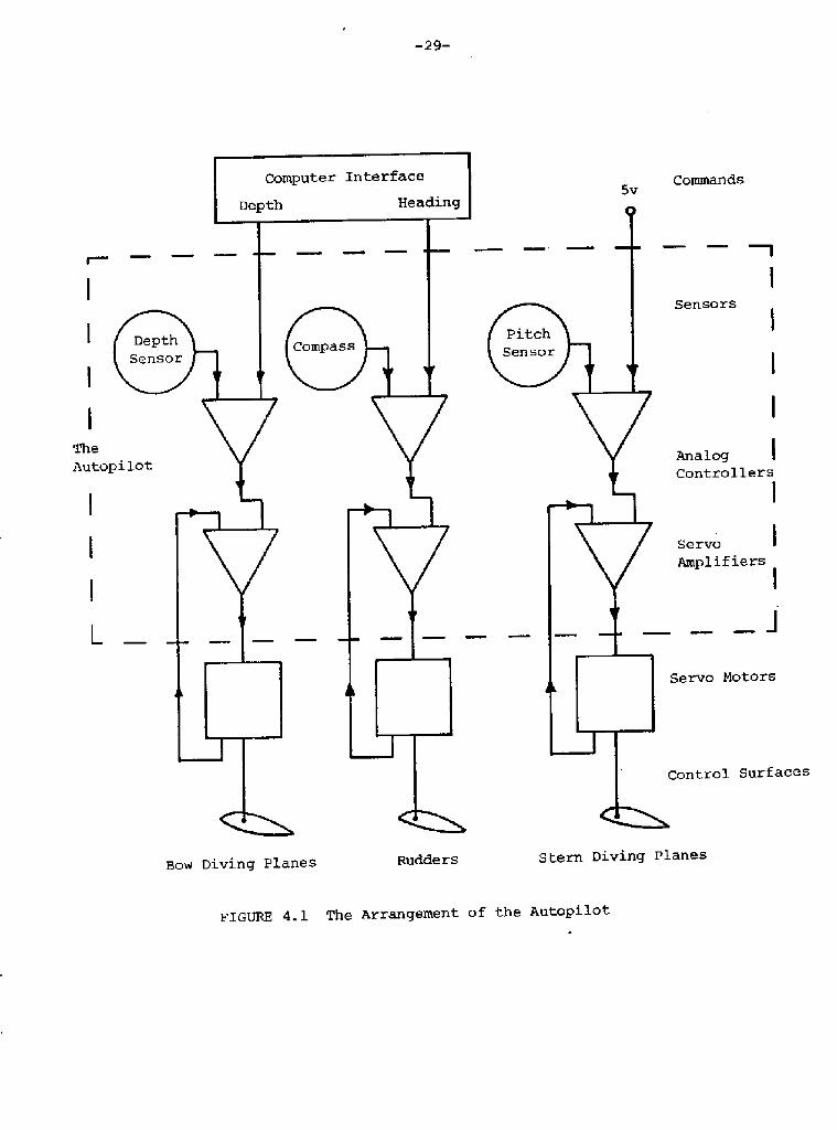
4.2 THE AUTOPILOT
The autopilot has real-time control of the robot; it carries
out the computer instructions with regard to course and depth and in
addition it COntrOlS the pitCh attitude Of the VehiCle. In the
original design the autopilot also controlled the roll attitude but
this was eliminated when it was observed that the vehicle was very stable
in roll.
The autopilot has three sections as shown in Figure 4.l.
The sensors, which sense the depth, attitude andheading of the vehicle.
The analog controller, which provides the controlsignals to instruct the control surfaces to move,depending on the differences between the desired andsensor determinations of the depth, attitude, andheading.
2.
3. The servo-amplifiers, which utilize the signals fromthe analog controller to provide the power necessaryto drive the servomotors.
The Sensors4.2. 1
The sensors on the robot determine the depth, the pitch angle,
and the heading of the robot. The outputs from the sensors are voltages
between 2.25 volts and 7.75 volts required by the analog controller.
With these subroutines an operation of the robot can be programmed very
simply as a series of statements calling these subroutines. Modifications
to the instructions can be made in the field with the aid of the control

Depth is determined by a commerical semiconductor transducer
which measures absolute pressure. This transducer is temperature
compensated and has a linear response in the region of interest. The
device has a working range equivalent to 135 feet of sea water and
would be replaced if the robot were required to operate at its maximum
design depth of 200 ft. The transducer would. be corroded by sea water
so that the ambient water pressure is sensed by a neoprene rubber
bladder filled with air. The output. from the transducer is passed
to an operational amplifier circuit to provide a signal making the
surface correspond to 2,25 volts and 100 feet correspond to 5 volts.
Pitch angle is sensed by two separate sensors. The first
using pressure difference measurements and the second using a pendulum.
The semiconductor pressure differential transducer is
connected to small rubber bladders filled with air, one is mounted
near the bow and the other near the stern. This instrument senses the
slight pressure difference due to pitch. It was found in operation
that the instrument required continual adjustment and recalibration.
However, when the system was dismantled. it was found that one of the
air bladders was not filled with air.
The pendulum attitude sensor has a lead pendulum attached to
a low friction potentiometer. The pendulum is place in an oil filled
container to provide damping.
The pendulum, depth sensor, and pressure difference sensor
were all placed in one housing and attached to the forward bulkhead.

The compass was developed to provide an output signal that
varied approximately linearly with heading. The compass uses an opaque
compass card on which a spiral is scratched to allow light through.
A light source is placed above the card and photo-potentiometers are
placed below. The output from the photo-potentiometers depend on the
position of the light arriving at them, which is a function of the
angular position of the compass card. Two photo-potentiometers 180
degrees apart were utilized to overcome the overlap at the ends of the
spiral. The computer selects the appropriate photo-potentiometer to
utilize.
The Analog Controller4.2.2
The analog controller is a proportional-derivative controller
which utilizes the differences between the command signals and the
sensor outputs to generate the control signals; these are transmitted
to the servo-amplifiers. The depth and heading commands come from the
computer while the attitude command requires that the robot should
re«ain horizontal. This is provided in the controller as a 5 volt
signal corresponding to zero pitch angle.
In the original design the bow and stern diving planes were
coupled together to control depth while the stern diving planes
controlled pitch attitude. Et was found to be very difficult to
develop a stable control system with this arrangement. Successful
operations were finally obtained when the two functions were decoupled
so that the bow diving planes controlled depth and the stern diving
planes controlled pitch.

-33-
The values of the gains and time constants in the controller
were predicted from theoretical analysis and by 1/4 scale model tests
in the propeller tunnel. These constants were adjusted during the
experimental program to provide a satisfactory controller.
4.2.3 The Servo-Amplifiers
The purpose of the servo-amplifiers is to utilize the signals
from the analog controllers, which specify control surface positions,
and then to provide the power to the servomotors to reach the
commanded positions.
The first stage of the servo-amplifier is a differential
amplifier which has an output proportional to servo-position error.
The output from this amplifier goes to the servomotor drivers which are
essentially solid state switches. During early testing of the
servo-amplifiers with their servomotors it was observed that small
oscillations occurred. The oscillations were inhibited by switching
off the servo-amplifiers for a few milliseconds several times per
second.
4.3 THE POWER SUPPLIES
The 12 volt automotive battery is connected directly to the
propulsion motor. The supply is then taken to the autopilot tube
where several of the regulators are placed. These regulated supplies
drive the electronics and the servomotors. There is an additonal
regulator in the computer tube with small rechargeable batteries to
provide an emergency supply for the computer.

-34-
There are three power supplies placed in the autopilot tube.
The first regulator delivers 10 volts at 2 amps for use in the autopilot
and the computer. The second supply delivers 5 volts to the operational
amplifiers in the autopilot, while the third power supply provides
5 volts and 2 amps for the servomotors.
The power supply in the computer tube takes the regulated
10 volts from the autopilot tube and the ll-l6 volts from the emergency
batteries and outputs the following dc supplies=
1. � 12 volts for the teletype interface.
2. + 5 volts for the memory.
3. + 10 volts for the computer, memory and interfaces
4. + 12 volts for the memory.
The 12 volt supply consists of a. 30 kHz oscillator and drivers
driving a toroidal autotransformer. The � l2 volts and � 5 volts are
also derived from the autotransformer. The + 5 volt supply is a series
pass regulator using the main 10 volt supply.
The 10 volt auxiliary supply uses batteries to supply a
regulated voltage slightly lower than 10 volts. The auxiliary batteriesonly deliver power when the main power supply falls below 9.5 volts.
It can deliver about one amp until the auxiliary batteries are discharged.
4.4 HISCELLAHEOUS ELECTRONICS
Xn addition to the main electronics described above there
are additional electronic systems associated with the positioning
and the safety of the robot. These have been built and installed but

-35-
not utilized during the development of the vehicle. They are planned
to be used in the future.
4. 4. l
The "ginger" is a separate system housed in a small PVC tube
placed in the battery compartment It could be isolated from the
remainder of the vehicle, however, since it has a quartz crystal tuned
to 200 kHz it was decided to utilize this as a precise clock for the
computer.
The pinger circuit provides an 8 millisecond burst at 8.33 kHz
precisely every second. The transducer, placed in the robot nose,
is tuned to 8.33 kHz by a series inductor. The position of the robot
is determined on the shore by means of a wet paper recorder with a
precise one second sweep utilizing two hydrophones.
During normal operation the pinger runs on the 10 v main power.
In case of power failure the pinger is supplied from two 9 volt
transistor radio batteries to keep the pinger operational for about
two days.
4.4.2 The 0 tical Cou ler
The purpose of the optical coupler is to provide a convenient
two-way transmission path from the on-board computer to the teletype
or the control panel with the robot in the water. This avoids the
problems of breaking and resealing watertight connections.
The optical coupler is in two halves which are brought
together and aligned when data is to be transmitted. On the robot side
there is a small PVC block in which there are three light emitting

-36-
diodes LRDs! and five photo transistors. On the shore side there isa mating PVC block with 5 LEDs and three photo transistors. Xn additionto the optical system there are four magnetic reed switches.
This coupler was designed and built but unfortunately damaged
during testing. Et has been rebuilt and can be used

-37-
5. THE ROBOT EMERGENCY SYSTEMS
There was some concern during the design of the robot about
the possibility of losing the robot due to failure of critical
components. The most probable failures were defined and designs were
considered which would minimize the resulting damage and facilitate
the recovery of the vehicle in the event of such failures.
The situations envisaged were as follows:
l. Collision with a fixed object.
2. Leakage of water into a critical tube.
3. Loss of battery power.
4. Operation at excessive depth.
To avoid fixed objects in the water it is necessary to have an
active sonar system with the avoiding action controlled by the computer.
The problems of water leakage, loss of power, and excessive
depth required systems to detect the problems and then to assist possible
recovery by releasing a tethered buoy and ballast.
COLLISION AVOIDANCE5.1
The collision avoidance sonar sends a pulse at 140 kHz in a
030 beam ahead of the robot. It receives any echo on the same hydro-
phone and transmits to the interface of voltage proportional to the delay
between the original and the return signals. This system is not fully
operational and is being developed. There have been problems with responses
from surface waves.

-38-
The'Water Sense Circuit
ease
Approximately 2K with Seawater
PressureThe Water Sense Tube
Sen
En dc ap
EIGt3RE 5. 1 The Emergency Systems

-39-
THE MISSION EMERGENCY SENSING SYSTEM5.2
The leakage of sea water into the critical PVC tubes is
detected by two bare wires placed in grooves at the bottom of each
tube. One of the wires is grounded and the other termed the water
sense line! is connected by a large resistor to the + 10 volts supply.
When there is no water in the tubes the "water sense line" is at 10 volts
while in the presence of sea water it is grounded. The loss of battery
power also dzops the water -sense line to zero volts. This system,
therefore, senses two emergency conditions.
When the limiting depth is reached the pressure sensor would
record the excessive pressure. An additional system based on a bourdon
tube and simple limit switches connected to the water sense line was
also designed and built. However, this device requires further
development as it is not reliable.
When the watez sense line goes to ground for any reason this
is signaled to the computer through the submarine interface. In
addition a simple circuit was devised to pzovide power to a solenoid
which would release the emergency marker and ballast system as shown
on Figure 5.1. This solenoid would be powered by C cells placed with
the releasing circuit in the "pinger" tubers
THE MARKER BUOY AND BALLAST RELEASE5,3
During preliminary design of the emergency recovery
arrangements various alternatives were considered including ballast
tank "blowing", the inflation of rubber bags, and the release of a

-40-
marker buoy and weights. This last named method of recovery was finally
decided upon for several reasons. First, the submarine sits very low
in the water and is difficult to spot, so that the method of recovery
should include a clearly visible marker, namely a buoy. Secondly, the
combined release of a buoy and a ballast weight was a much simpler
mechanical system than blowing ballast tanks or the gas inflation of a
bag.
The design finally selected uses a streamlined marker buoy
mounted on the top skin of the submarine in a fiberglass cradle.
The buoy is weighted to float vertically when it is released. One end
of the buoy is attached to a 100 ft. line which comes from a reel placed
in the battery compartment. A release mechanism placed on the rear
bulkhead has a series of spring loaded levers which simultaneously
release the marker buoy and a five pound mass of scrap metal mounted
under the battery. This release system was nearly operational
towards the end of the experiments. The mechanism had been designed
and built and is being trimmed to provide reliable operation.
5.4 RECOVERY SYSTEM USED FOR OPERATIONAL MXSSIOHS
During the actual missions of the vehicle, since the
emergency system were not operational it was decided that the robot
should tow on the surface a small streamline float. This was a
satisfactory solution for development operations,

6- THE ROBOT TEST PROGRAM
The test program for the robot vehicle was completed in several
phases. The individual components were f irst developed, then assemblies
were tested and finally the complete vehicle was operated.
The main developrrLent of the mechanical system was associated with
the drives for the control surfaces. The bow diving plane assembly
was operated for many hours in a water tunnel. The bow servo-system was
coupled to the computer interface and programmed to provide changes in
angle of attack of the control surface. This test demonstrated the
reliability of the system.
The electronic systems were calibrated before assembly and
simulated missions were conducted in the laboratory. These missions
tested the software and the hardware.
6.l INITIAL OCEAN TESTING
The initial test program for the robot was conducted to
determine the basic operational characteristics of the vehicle. The
concern was the inherent stability and maneuverability. The vehicle was
operated before the computer, autiopilot and software were functioning
reliably, the control surfaces were therefore set at fixed positions.
The propulsion motOr was controlled by a simple electrOnic timer.
The robot was first ballasted with a lead sheet in the
battery compartment. It was decided that the vehicle should have

-42-
approximately one pound positive buoyancy. A relatively simple procedure
was devised to facilitate ballasting. The vehicle was submerged
horizontally to a depth of one foot and then released. The elapsed time
to surface was determined. A simple theoretical analysis showed that
the vehicle should take approximately seven seconds to reach the surface
with one pound of positive buoyancy. The ballasting was adjusted to that
the robot surfaced horizontally with approximately the correct elapsed
time.
The first operational tests were conducted to determine the
minimum turning radius. On the surface it was found that this was
about 25 feet. The turning radius underwater was later found to be
smaller than this value because the rudders were fully immersed.
These initial tests confirmed the mechanical integrity of
the vehicle and indicated that the rear control surfaces were adequately
sized for stability and maneuverability. There was some doubt about
the effectiveness of the bow diving planes as these had half the
surface area of the rear control surfaces.
6.2 DEVELOPMENT OF THE COHTROLLED VEHICLE
The computer and autopilot were installed and the vehicle
was operated in a large sea water swimming pool and also in a cove
near Castine using the specially designed catamaran to transport the
robot. A series of surface maneuvers were first attempted including
circles and figures-of-eight. These simple operations were successful
with the propulsion motor starting and stopping as required and the
control surfaces moving as commanded. Initial attempts at making the

robot dive were irratic. There were occasions when the robot would not
dive, while on other occasions the vehicle would not stay on the surface.
It was concluded that the autopilot was not functioning as designed and
that the bow diving planes were too small.
At this point it was decided to redesign the bow diving planes
and increase their size and also to make changes in the autopilot.
After these changes were made the robot operated successfully.
Further simple maneuvers were carried out and the robot was sent
out-and-back on prescribed headings and at shallow depths. Unfortunately,
during one of the early successful operations the vehicle struck an
underwater object which damaged the bow planes. Repairs were made after
the accident but the operation of these planes were impaired until the
whole structural arrangement was later straightened.
6. 3 DATA COLLECTING MISSIONS
The robot was programmed to go and return on preset heading
and record the water temperature and the operating depth every second.
The temperature was measured by thermistor. It was put in series with
a resistor, placed across the 10 volt supply and calibrated to provide
output voltage as a function of temperature. In the robot the
thermistor was arranged to measure water temperature just outside the
nose Xt was coupled to the computer interface through one of the
spare leads in the autopilot tube.
During the final test the robot pulled away from the pier
after being given the start instruction. It turned to its preset
course which was parallel to the shore and dived to its preset depth

-44- O C4O C4CV
O O C4
OCP 0 0S
0 V!
paar 'qqdaa

-45-
of three feet, It continued on this course for two minutes and then
turned through approximately 180 degrees to return. lt finally surfaced
about 100 feet from the pier.
The robot was then returned to the laboratory where the data
stored in the memory was printed out as octal numbers and also punched
on paper tape in binary form. These data were changed to decimal
numbers and recorded.
The measurements of depth and temperature as functions of
time for one data collecting operation are presented on Figure 6.1.
The temperature was remarkably uniform for the operation,
with a temperature variation of less than one degree. The variation of
depth during the mission shows several interesting features. The
robot begins diving after about 8 seconds from start, it overshoots the
preset depth by a foot and then settles down to the prescribed depth0after one or two oscillations. During the 180 turn the vehicle rises
1 1/2 feet and then returns to preset depth after completing the turn.
A scuba diver stationed near the path of the robot observed
that it was very stable both in pitch and heading.

-4e-
a. On the Beach Before Launching
b. Underway with Computer Control
FIGURE 6. 2 The Operational Robot

-47-
7. A WINDMILL POWERED BUOY
Many buoy systems require electrical power to perform their
functions. For these installations, simple battery systems actuated
by environmental controls are used. However, for certain larger buoys
a larger, reliable energy source is required to provide the power to
collect and transmit data.
Wind power is readily available on most parts of the ocean' s
surface and coupled to a battery storage system could provide the power
for these large buoys. Windmills are a proven practical source of power
for remote applications, such as pumping water on farms. It was therefore
decided to design and build a simple inexpensive windmill system placed
on a buoy.
7.1 EQUIPMENT DESIGN
The design problem was separated into two areas, the buoy
and the windrnill.
7.1.1 The Buoy
The buoy must serve as a stable platform for the windmill and
associated test equipment. It should be simple, inexpensive and allow
various mounting arrangements for the windmill and experimental equipment.
It was decided that the windmill should be attached to a pylon placed in
the middle of the buoy.
Various methods of constructing the buoy were considered and
fianlly a design utilizing an available inner tube was selected. A
truck inner tube of five feet diameter with a wooden frame of

FIGURE 7.1 The windmill Buoy

2" x 4" placed across it was used, as shown in Figure 7.1. A section
of aluminum mast from a sloop was used as the pylon. Two vanes were
placed aft to provide directional stability.
The buoy was moored by means of a chain bridle hung on the
center line and attached to a swivel and line leading to the anchor.
7.1. 2 The Windmill
Several methods can be used to generate power from the wind
Vertical axis windmills such as the Savonius rotor may be used in
addition to several types of axial axis designs.
The Savonius rotor is simple and rugged, but it is
inefficient and requires large areas of material to generate power.
Horizontal axis windmills can be roughly catagorized as
multibladed or propeller type. The multibladed has good starting
characteristics but is not as efficient as the propeller type. It was
felt that good starting characteristics were important for a remote
windmill so that the multibladed windmill was selected.
The windmill was designed to drive a hub-generator removed
from a bicycle. The characteristics of the generator were first
measured by mounting it in a lathe chuck and driven at various speeds
by the motor. The reaction torque was determined with a spring
balance and the voltage and current were measured with electrical
meters. The generator load was prOVided by a 400 ohm rheostat and
it was found that the most efficient load was about 50 ohms. A
fixed 50 ohm 10 watt resistor was then attached to the generator.
The starting torque was measured with the lathe chuck stationary as
-50-
itch
Fillet
5I Qll
FIGURE 7.2 The Nindrmi11 Design

-51-
,20 lb ft. This value was used to estimate the size and number of
windmill blades that wouLd start with a wind of five knots.
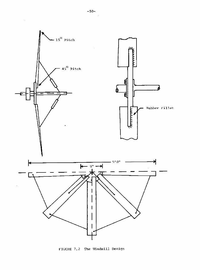
The blades of the windmill were modeled as flat plates and
it was found that the optimum leaving angle to give the best starting
conditions was about 36 degrees from the tangential direction. With
this angle and the measured starting torque for the generator, it was
determined that eight blades thirty inches long and 7 L� inches wide
would start. at just below 5 knots
The blades were made from L/32" aluminum formed over a
wooden template to give camber and added stiffness. The blades were
twisted to prevent stalling. The blades were attached to a plywood
hub carried by the generator. They were supported by lacing wires
at the tips and by wires from a 12 inch post placed at the center of the
hub, Figures 7.1 and 7.2!. The whole assembly was attached to the
pylon on the buoy.
7.2 EXPERIMENTAL PROGRAM
The windmill powered buoy was moored in 30 feet of water
near the dock at Castine. Xn this position it was exposed to the
prevailing south westerlies. The mornings tend to be calm with the
wind increasing to 10-15 knots by early afternoon. The windmill was
removed from the pylon at night.
The buoy proved capable and stable and the vanes directed
the windmill into the wind regardless of the original direction.
-52-
The windmill was found to start at 4 knots with no electrical
load and operated in winds of 25 knots. During handling four blades
were bent. These were repaired but the blades were weakened. On the
second day of testing before test data was taken the windmill failed
in a 20 knot wind. One of the lacing wires parted and the blades made
contact with the pylon.
7.2.1 Conclusions and Recommendations
The buoy and windmill design proved that a simple system
could be used to generate power. The buoy was entirely satisfactory
but the windmill construction was not rugged enough. However, to
produce a more sturdy design would require thicker blade material which
would be difficult to fabricate without special facilities.

-53-
8. CABLE STRUHMZNG EXPERIMENTS
"Cable strumming" is the name given to the self-excited
vibration of cables caused by ocean currents. This strumming is
important to the oceanographic community because the movements of
the cables can cause incorrect reading of instruments supported by
such cables. Xn addition, the "fish bite" damage found on many
cables in the ocean may be aggravated by these vibrations.
The cause of the strumming is considered to be the regular
shedding of vortices from the cable. These vortices form the
"Karman vortex street" which occurs downstream from cylinders at
low Reynolds numbers. The shedding of a vortex induces a transverse
force which moves the cable perpendicular to the current. Another
vortex of opposite sign is then shed, producing an opposing force
and opposite cable movement. This alternate shedding of vortices
sustains the strumming action. The vortex shedding between nodes
of the vibrating cable appears to be synchronized by the cable's
own movements.
A large number of experiments have been performed by other
experimenters with rigid cylinders in wind tunnels and water tunnels.
A few wind tunnel and water tunnel experiments have also been carried
out with short lengths of cables. These experiments have produced
a considerable amount of data concerning rigid cylinders and short

-54-
cables, but an extrapolation of these results does not necessarily
correspond to the realities of cables thousands of feet long in the
ocean environment. Recent experiments have been conducted on such
long cables in the ocean. However, the experimental data have not
yet been adequately analyzed because of the complications of various
mass loadings and varying current velocities along these cables. in
1974 preliminary experiments on 250-yard and 50-foot cables were
conducted and reported in reference l. These experiments were carried
out on cables which were not well isolated from outside vibrations
and there WaS dOubt abOut the Current VelOCity meaSurementS. The
experiments described here used an improved test arrangement and
testing technique.
THE TEST ARRANGENENT8.1
Xt was decided that approximately 75-foot-long test cables
would be used. lt was expected that the data from these experiments
would assist in the interpretation of information from very long cables.
The main emphasis of the experiments was the provision of solid end
supports for the cable and the development of good instrumentation
and recording techniques.
Cables Tested8.1. 1
The cables tested in this experiment were as follows:
l. 7/16" Sampson "Blue Streak".
2. 0.275" U.S. Steel wire rope.

-55-
A 0 0
0'x

3. Philadelphia Resin Corporation "Phillystran"Kevlar rope.
4a. 0.154" Philadelphia Resin Corporation Kevlarrope with 3 twisted conductor center, andanti-strumming fairings woven around the outsideof the rope.
4b. Same as above but with fairing removed.
For technical details, see Table 8 l.
The Ex erimental SiteS.l. 2
The controlled conditions necessary for the cable strumming
experiment were as follows:
A region in which to place the test Cable wherethe current would be uniform along the lengthof the cable and perpendicular to it at any givenmoment.
2. The current would vary slowly as a function oftime over a large velocity range.
3. The site would have to be dry at low tide so thatthe equipment could be set up.
A suitable test site at a sandbar near Castine, Naine, was
used for the preliminary experiments of reference l. The sandbar
was exposed at low tide, as shown on Figures G.l and 8. 5. As the tide
came in, current velocity slowly decreased from a high of 3 ft/sec
to a low of zero at high tide!. Several traverses of the test
site were made with an electromagnetic current meter at various times
while the tide was coming in. The current varied up to 2.5% about
the mean along the test cable in a 3-minute round trip from one end
of the cable to the other with several current measuring stops each
way.

-57-
TABLE 8. 1
Cables Tested
Sam son "Blue Streak"
12-strand single braid, polyester and propylene half andhalf!, 5,000-1b breaking strength, 7/l6" nominal diameter,.39" measured diameter under tension, 64.78 g/m dry,93. 5 g/m wet.
U.S. Steel Wire Ro e2.
3x9 torque balanced, polyethylene coated, closed swagedsocked, galvanized plow steel, 4, 000-lb breaking strength,.275" measured diameter, 108.3 g/m.
Philadelphia Resin Corporation "Phillystran" Ps 29-C395
Construction 7x7 Ps 29-B105! "Kevlar" rope with apolyurethane jacket, 17,000-lb breaking strength, 3/8"nominal diameter, .485" measured diameter, 113.2 g/m.
Philadelphia Resin Cor oration Anti-Strumming Cable4a.
Same as above, but with anti-strumming fairings removed.4b.
Braided polyurethane impregnated Kevlar, with 3 twistedconductors down center, 2,000-lb breaking strength,anti-strurmning fairing woven helically into Kevlar covering,.154" measured diameter under tension with anti-strummingfairing removed.

-58-

Pre grin the Test Site8.1.3
It was decided to support the test cables using six piles
driven into the sandbar, as shown on Figure 6. 2. At each end of the
test section, one pile the inner one! was used to support the test
cable and two outer piles were arranged to take the cable tension
load. The piles were constructed from 10 � foot-long steel pipes and
these were driven into the sandbar with water jets so that only a
few inches were left exposed above the sandbar.
A sheave attached to a length of pipe was bolted to the
inner piles to support the cable about two feet above the sandbar.
These sheave attachments were removed after the test runs to allow
passage over the sandbar.
8.1.4 Instrumentation
Instruments were needed to measure the frequency and
amplitude of the test cables, the speed of the ocean currents, and
the tensions in the cables. In addition, a recording instrument was
required for the various instrument outputs.
Frequency and Ar rpH &de Heaauremenfs
The frequencies and amplitudes of the cable vibrations were
measured with accelerometers and with a special direct reading
device, described later, termed the "fish".
The accelerometers were single-axis, general-purpose, damped
accelerometers made by Entran Devices Inc. These instruments had a
range of + 10 g and were attached to sheet metal mounts which enabled
them to be clamped to the cables and moved along the cable when necessary.

-60-

� 61�
FIGURE 8. 4 The "Fish" Attached to the "Blue Streak" Cable
FIGURE 8.5 The Experimental Site fram Holbroak Cove

-62-
The amplitude and frequency of the test cables were also
measured directly using a transducer built for the purpose, as shown
on Figures 6.3 and 8.~~. This transducer consisted of a rotary potenticmeter
connected by an arm to the cable. The potentiometer was housed in a
streamlined and neutrally buoyant fairing with tail fins for
stabilization termed the "fish". A second hinged arm was made to
stabilize the fish as it streamed behind the cable. The fish remained
essentially at rest behind the cable as the vibrating cable moved the
supporting arms and the potentiometer shaft. This device was designed
and developed using a small water tunnel. The calibrations of the
transducer in the test arrangement show that it had 0. 66 volts/inch
of cable deflection.
Curx'cnt Mater's
The main current meter used in the experiment was an
electromagnetic EM! current meter with a sensitivity, after
signal processing and amplification, of 2.75 ft/sec per volt. This
instrument used an electromagnetic coil to produce an a.c. magnetic
field and a pair of electrodes in the flowing water to measure
the potential difference produced by the moving conducting fluid
in the magnetic field.
Two small propeller current meters were occasionally used
as back-up meters-.
The current meters were mounted on stands which were placed
on the sandbar about two feet downstream of the test cables.

-63-
A survey instrument for traversing the current meters along
the length of the cable was also constructed. The design of this
device was similar to the "fish" described above. The current meter
was supported by the body of the "fish" while the arms of the device
were hooked around the cable. This device could be pulled along the
cable to measure the current. speed just downstream of it.
Tensiomeies
A cylindrical tensiometer with a sensitivity of about
l00 lb per volt was used to measure the average and the oscillating
tensions in the cables This device was calibrated in a testing
machine and the calibration was confirmed from time to time by
supporting known weights from the transducer.
Beeorder
A four-channel Tanberg FM tape recorder was used to record
the instrument measurements. One channel was used to provide vocal
comments and descriptions of the signals being recorded, in addition
to recording data.
8. 2 EXPERIMENTAL TECHNZQUE
The procedure used in the cable strumming experiments was
similar for each test series. The cable was set up on the sandbar
at low tide; the test results were recorded on the rising tide
and the apparatus was removed by divers near high tide. Two boats

-64-
were used in the experiments; a l7-foot boat of special design with
a large area at the stern for apparatus and equipment, and a small
skif f.
8. 2. 1
The boats arrived. around low tide and the test cables were
set up with the various transducers, as shown in Figure 8.2. The
setting-up procedure began with the insertion and bolting of the
sheave arrangement in the inner piles. The "come along" winch was
placed at one end of the test region and the tensiometer was placed
at the other end. The test cable was placed over the sheaves and
shackled to the winch and to the tensiometer. The various amplitude
transducers were then attached to the test cable. A guide wire was
fixed to the inner piles to support all the electrical wires from
the instrumentation. As each transducer was set up, the electrical
wires were taken to the guide wire and supported by twisted copper
wire loops about every five feet. The instrument wires were brought
aboard the instrumentation boat and connected to the instrument
amplifiers and the tape recorder. Marker buoys were placed so that
boats would not go over the test cable. Finally, divers took the
boat anchors to suitable spots and firmly placed them into position
to withstand the loads imposed by the currents over the sandbar.
Data Collection8. 2. 2
During the setting-up procedure, the instrument zeros
were recorded and the test cable was plucked in air. The zero

-65-
for the EM current meters was obtained after the water had risen above
the meter by placing a hand over the instrument.
Data were recorded as soon as the current meter output
stabilized; this depended on the depth of water over the sandbar andthe sizes of the waves. The two accelerometers and the "fish"
transducer had separate channels on the recorder while the tensiometer
or KM current meter were put on the remaining channel.When the current velocity reached a plateau, divers went
down to the winch to adjust the cable tension. Short data segments
were recorded at different tension levels from 60 to 700 lbs
see Table 8. 2! .
At various times divers swam along the cable to adjust the
orientation of the accelerometers, to remove seaweed, and to checkthe cable and instrumentation. In addition, some accelerometer
transverses were made by moving one accelerometer relative to the
other.
When the current velocity was low enough so that the cable
strumming stopped, scuba divers went down and plucked. the cable
to determine the response in still water.
8. 2.3
It took two scuba divers approximately 20 minutes to
dismantle the testing apparatus at high tide with no current.
The divers swam to the accelerometers, took them off the
test cable, coiled their wires, and brought them aboard the boat.

-66-
TABLE 8.2
0. 485" Diameter
Vd ft/sec Td lbs
12. 02. 17 120
ll. 5
ll. 7
ll. 5
2. 17 128
131
135
11. 5 152
16412. 0
ll. 6 186
20912. 1
228ll. 25
2501 l. 4
11. 25
10.38
10. 5
10. 1
280
304
328
350
3789.0
3789. 38
7. 88 425
Test Data With Tensian varied Kevlar Cable,
2. 17
2. 17
2.17
2. 17
2. 17
2.17
2.17
2.17
2 17
2. 06
2. 06
l. 84
1 84
1. 84
l. 51
. 2235
. 2142
. 2177
2142
. 2142
.2235
.2161
.2247
.2095
.2119
.2095
.2037
.2060
.2219
.1977
.2060
2109

-67-

-68-
The other instruments were also carried to the boat. The pipe inserts
were then unbolted and handed up to those on board. These pipe
inserts unfortunately could not be left on the sandbar because they
would have been a hazard to navigation. The marker buoys, guide rope,
test cable and winch were then brought to the boat. Finally, the
divers loosened the stern anchor and climbed aboard.
8. 2. 4 Anti-Strummin eriment
The last cables tested were cables ¹4a and ¹4b. It was
decided that the effectiveness of the anti-strumming fairing could
be best evaluated if both cables could be tested under exactly the
same conditions. The problem was to place both cables in the same
current, with the same tension, at the same time.
The arrangement of the cables was the major difference
between this test and the previous tests, as shown in Figure 8,6, 8.7
and 8.8 a pulley block was hooked to the winch. The faired and
unfaired parts of the original cable were not separated, and the
cable was threaded thxough the pulley to the point where the cable
changed from faired to unfaired. The faired part of the cable was
stretched across the tops of the sheaves on the pipe inserts. The
unfaired part was wrapped once around each of the two sheaves so
that the unfaired cable was separated from the faired cable by the
diameter of the sheaves. Both the faired and unfaired cables were
texminated at the western end beyond the sheave by being cable-clamped
to the same thimble. The thimble was then shackled to the
tensiometer.

-69�
FIGURE 8 7 The Anti-Strumming Experiment Accelerometer isAttached to Unfaired Cable
FIGURE 8. 8 Anti � Strumming Experiment Eastern Fnd

-70-
The "fish" was attached throughout the experiment to the
same spot on the unfaired cable. Only one accelerometer was
functioning so it was traversed along the unfaired cable, and also
positioned on the faired cable, above the "fish", or above the
point where data had recently been taken on the unfaired cable.
To determine the tension on each of the cables, the tension shown
on the tensiometer had to be divided by two.
8. 3 EXPERIMENTAL RESULTS
The recordings made in Castine, Maine, were played back
through a four-channel strip chart recorder at M.I.T.; a sample
is shown in Figure 9. The analysis is not yet complete. Many
sections of data must be processed through a spectrum analyzer.
Only preliminary results are therefore reported here,
Preliminary analysis indicates that the strouhal numbers
d fd/Vd! computed for the "Blue Streak" ranged from .14 to .18
with .17 dominant. By dominant it is meant that the number is the
average non � lock-in observed strouhal number. The 485" diameter
Kevlar cable's strouhal numbers ranged from .2 to .22 with .21
dominant. The unfaired anti-strumming cable's strouhal numbers
ranged from .16 to .18 with .17 dominant. The faired anti-strumming
cable's strouhal numbers ranged from .12 to .13 with .123 dominant,
using the same diameter for strouhal calculations as the unfaired
cable. The fairing was irregular so that accurate diameter
measurements could not be taken.

-71-
1 sec accelerometer ¹1.34"/cm
I I accelerometer ¹2.14"/cm
EM current motor
V< = 1.94 ft/sec
"fish"
.152"/cm
f = 14 hertzd
S = .16
pZGURE 8. 9 Representative Transducer Outputs for the Wire Rope/Tension 190 lb.

-72-
$.P., f:
+
',j, '7
' 11 i<''I 7 =
17'1
+I
,; I<.'ij,.tgji-jI
Pt
l j.!I. ~
4 5 62 3
Non-Dimensional Velocity, U
FIGURE 8.l0 The Results of a "Blue Streak" Cable Test,Diameter 0. 39".
LJ ff,
Aj'
ifi
tjj..~;
- 'I~ '
-if 17<

-73-
Varying cable tension, while keeping at a constant velocity,
did not alter the frequency of vibration a significant amount, as
shown in Table b.2.
Lock-in phenomena were observed at modes 1 through 5.
Lock-in is said to occur when the cable continues to vibrate at a
multiple of its fundamental natural frequency in water while the
current velocity varies. Or, whenever the cable vibrates at a mode
rather than at the frequency of shedding predicted by the strouhal
number, current velocity and cable diameter f = SVd/d!.
Figure 8.10 plots a nondimensional frequency F against a
nondimensional current velocity V. The nondimensional frequency is
the ratio of the observed frequency fd to the fundamental natural
frequency in water fl. F therefore corresponds to the mode of the
cable's vibration, assuming a constant added mass. The nondimensional
velocity is the ratio of the observed current velocity vd to that
velocity which would cause the cable to shed vortices at its
For detailsfundamental natural frequency in water Vl = fd/,,!.
of calculations, see Symbols and Definitions.
The anti-strumming fairing decreased the strouhal number
from . 17 to . 123; a strip chart recording is shown in Figure 8. 11.
Another way of looking at this is to say that the effective diameter
was increased from . 154" to . 213" by adding the anti-strumming
fairing. The maximum amplitude of the unfaired cable was .114" and
the average amplitude was approximately .085", or 74% of the cable's
diameter maximum and 55% of the diameter average. The maximum

accelerometer ¹1
.04"/division
fd = 18 hertz
1 division
n f ishn
. 038" /dzvxsxon
fd = 25 hertz
Anti-Strumming Experiment. Accelerometer ¹1 is onthe Faired Cable. The "Fish" is on the UnfairedCable. The Tension is 74 lb, Current Velocity is
1.88 ft/sec.
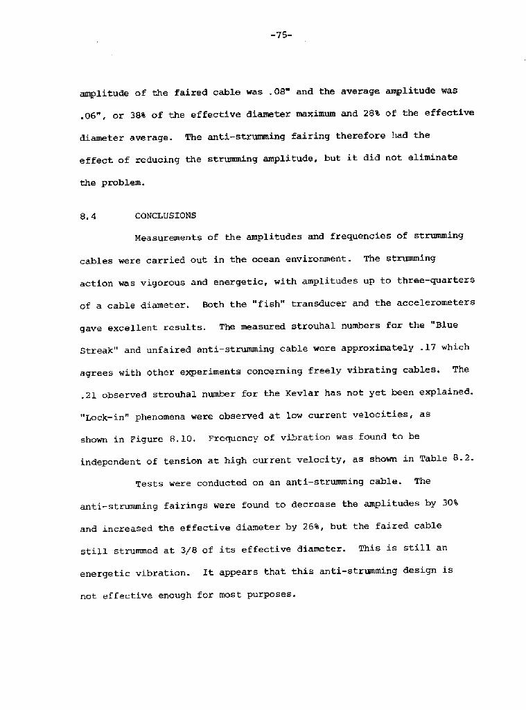
amplitude of the faired cable was .08" and. the average amplitude was
.06", or 38% of the effective diameter maximum and 28t of the effective
diameter average. The anti-strumming fairing therefore had the
effect of reducing the strumming amplitude, but it did not eliminate
the problem.
CONCLUSIONS8.4
Measurements of the amplitudes and frequencies of strumming
cables were carried out in the ocean environment. The strumming
action was vigorous and energetic, with amplitudes up to three-quarters
of a cable diameter. Both the "fish" transducer and the accelerometers
gave excellent resul.ts. The measured strouhal numbers for the "Blue
Streak" and unfaired anti � strumming cable were approximately 17 which
agrees with other experiments concerning freely vibrating cables. The
.21 observed strouhal number for the Kevlar has not yet been explained.
"Lock-in" phenomena were observed at low current velocities, as
shown in Figure 8.10. Frequency of vibration was found to be
independent of tension at high current velocity, as shown in Table 8.2.
Tests were conducted on an anti-strurmning cable. The
anti-strumming fairings were found to decrease the amplitudes by 30%
and increased the effective diameter by 26%, but the faired cable
still strummed at 3/8 of its effective diameter. This is still an
energetic vibration. It appears that this anti-strumming design is
not effective enough for most purposes.

-76-
RECOMMENDATIONS8.5
Cables tested in this study were perpendicular to the current.
Future tests should be conducted with yawed cables, and with mass
loaded cables.
Other anti-strumming cable designs should also be tested.
REFERENCES8.6
Ocean Engineering Report No. 74-l9, l974

-77-
SYMBOLS AND DEFINITIONS
Vd = observed current velocity
fd = observed frequency
Td = observed tension
u = mass per unit length in water, including "added mass"
L = length of cable
f = n/2L! vT/vu! = frequency at nth moden
f = fundamental frequency in water. In practice, the fundamental was1 observed at one tension, and scale from the above formula for
other tensions.
d = diameter of cable
Sd = d fd/Vd = observed strouhal number
S = dominant strouhal number for cable tested
F = f /f = the mode of the cable's vibrationd l
V = fld/s = the current velocity which would drive the cable at itsl fundamental natural frequency
V = V /V = V S/f d = a dimensionless velocityd 1 d 1

-78-
9. A PORTABLE FLOATING BREAKWATER
In 1973 Dr. Buckminster Puller approached the Summer Laboratory
with a proposal for' a floating breakwater. He assumed the breakwaterwould he of cylindrical form, portable and environmentally safe.
The first attempt used inner tubes from automobile tires,
three quarters filled with water and pressurized with air. A plasticcover was placed over the tubes to form the cylinder. After deploymentin Castine Harbor seas ripped the cover. In 1974 a larger model usingtruck inner tubes was built with a stronger cover. This model was60 feet long and 6 feet in diameter. Due to the weight and theinstability of the water filled tubes this model could not be properly
assembled.
9.1 BREAKWATER DESIGN
The third model used plasti.c water pipe to form the hoops.
Plastic couplings were used to join the two ends of each pipe tocomplete the ring. Weights were placed on the hoop to providestability so that the rings would float in a vertical plane.
Preliminary calculations showed that with 1 1/2 diameter
pipe, weights of approximately 6 lb should be added to each hoopto make the breakwater float with one quarter of the diameter above
the surface.

-79-

� 80-

-81-
The cover used the previous year was again utilized.
Grommets were placed. in rows every 6 feet along the cover to secure
the hoops, as shown in Figure 9. 1. "D" rings were placed at the ends
of the cover to take the mooring lines.
The breakwater was assembled on land and deployed with two
men using a rowboat. It was placed between an island and a rock reef
at the testing site. One end of the breakwater was attached by a
rope and chain to a rock on the island while the other end was secured
by an anchor in a ledge of the reef. Swivels were placed at the ends
of the breakwater. Two additional mushroom anchors were placed as
shown on Figure 9.2 to prevent. over-stressing of the mooring lines.
TEST PROGRAM9.2
The breakwater was set up at the test site and simple wave
height indicators built and installed upstream and downstream of the
breakwater. However, during the twelve days that the breakwater was
installed no significant waves were observed so that the effectiveness
of the breakwater was not determined.
During the deployment structural problems occurred. It was
found that plastic pipe deformed too easily, especially where the loads
were high, at the two ends of the breakwater. Hoops of larger diameter
2 inch pipe were then used for the end rings. In addition water leaked
into the pipes when the tubes were buckled.

-82-
9. 3 CONCLUSIONS AND RECOMMENDATIONS
The breakwater design has been improved but there are several
possible improvements. The plastic pipe used is obviously not strong
enough and should be replaced with stiffer pipe. It has been suggested
longitudinal strength members should be used. This would however,
decrease the portability and ease of storage.

-83-
10. PRELIMINARY SONAR AND MAGNETOMETER SURVEY FOR VESSELSDESTROYED IN THE PENOBSCOT EXPEDITION OF 1779
During July 1975 a preliminary survey was conducted to determinethe feasibility of locating additional vessels from the ill-fatedPenobscot Expedition of 1779. The survey was conducted in two parts.First, a detailed survey of the DEFENCE a Revolutionary War privateerof approximately seventy-five feet in length! to gather background dataon target characteristics of a known vessel of this fleet and to get abetter understanding of the DEFENCE site, and secondly, a preliminarysurvey of possible sites up the Penobscot River to investigate thefeasibility of surveying in the river and to locate targets for further
investigation.
10. 1 BACKGROUND
In the summer of 1779 the State of Massachusetts formed an
expeditionary force of forty ships to capture Fort George at Castine Maine! in What WaS then the eaStern part Of MaSSaChuSettS. The fleetconsisted of three Continental Naval Vessels, three vessels of theMassachusetts State Navy, one from New Hampshire, twelve privateers andtwenty-one transports which laid siege to Castine on July 24, 1779.There were sporadic attacks made on Port George but without success.
On August 14, 1779 a British force of six large ships arrived at Castineand the American fleet immediately took flight up the Penobscot River

-84-
O LQ
0
C S I
Q 8 00
l5
to 0fd Vj

Most of the ships were subsecuently burned and/or blown up by their crews
to prevent their capture by the British. This was a major disaster for
the Revolutionaries, but it, now provides us with invaluable historical
artifacts from the Revolutionary War.
The DEFENCE, a Revolutionary War privateer was located four
years ago by the Ocean Engineering Summer Laboratory. Since its
discovery a limited amount of archaeological work has been accomplished
consisting of mapping of the site, limited excavation of the hull and
a limited recovery of artifacts.
10. 2 THE SURvEyS
The wooden hull appears to have been burned down to the
waterline, but below that, the wooden hull which sits in the mud is in
very good condition. The extensive side scan sonar surveying of the
site shows the hull, which barely projects above the mud bottom to be a
very good target. A mast from the vessel was found about sixty-five
feet to the west of the site, and a one-foot diameter by twenty-two foot
long oak log partially buried in the mud which is not related to the
wreck was the only other object found in the area.
A rotary side scan SOnar develOped by Dr. Edgerton proved very
valuable in surveying the site. This device allows the boat to anchor
near a suspected target, the rotary side scan sonar is rigged and slowly
rotated so that distance and bearing to any target is read. If this
information is plotted, a good site plan of bottom targets can be
produced. It can also be used to direct divers to a target for
investigation.
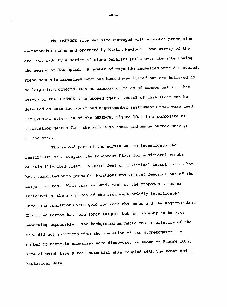
The DEFENCE site was also surveyed with a proton precession
magnetometer owned and operated. by Martin Meylach. The survey of the
area was made by a series of close parallel paths over the site towing
the sensor at low speed. A number of magnetic anomalies were discovered.
These magnetic anomalies have not been investigated but are believed to
be large iron objects such as cannons or piles of cannon balls. This
survey of the DEFENCE site proved that a vessel of this fleet can be
detected on both the sonar and magnetometer instruments that were used.
The general site plan of the DEFENCE, Figure 10.1 is a composite of
information gained from the side scan sonar and magnetometer surveys
of the area.
The second part of the survey was to investigate the
feasibility of surveying the Penobscot River for additional wrecks
of this ill-fated fleet. A great deal of historical investigation has
been completed with probable locations and general descriptions of the
ships prepared. With this in hand, each of the proposed sites as
indicated on the rough map of the area were briefly investigated.
Surveying conditions were good for both the sonar and the magnetometer.
The river bottom has some sonar targets but not so many as to make
searching ixnpossible. The background magnetic characteristics of the
area did not interfere with the operation of the magnetometer A
number of magnetic anomalies were discovered as shown on Figure 10.2,
some of which have a real potential when coupled with the sonar and
historical data.

-87�
cal
PIC URE 10, 2 Preliminary Survey of the Penobscot River

-88-
A complete survey of the Penobscot River site should be made
with special emphasis on the few promising targets discovered in the
preliminary survey. Diver investigation of the targets was not
conducted due to time limitations. This is an important aspect of the
survey which can be facilitated by the use of rotary side scan sonar
which allows the divers to be directed by the surface command right to
the target without a detailed diver search of the area
