observation of saturation of fidelity decay with an atom
TRANSCRIPT

Observation of Saturation of FidelityDecay with an Atom Interferometer
The Harvard community has made thisarticle openly available. Please share howthis access benefits you. Your story matters
Citation Wu, Saijun, Alexey Tonyushkin, and Mara G. Prentiss. 2009.Observation of saturation of fidelity decay with an atominterferometer. Physical Review Letters 103(34101).
Published Version doi:10.1103/PhysRevLett.103.034101
Citable link http://nrs.harvard.edu/urn-3:HUL.InstRepos:10591648
Terms of Use This article was downloaded from Harvard University’s DASHrepository, and is made available under the terms and conditionsapplicable to Open Access Policy Articles, as set forth at http://nrs.harvard.edu/urn-3:HUL.InstRepos:dash.current.terms-of-use#OAP
Observation of Saturation of Fidelity Decay with an Atom Interferometer
Saijun Wu,* Alexey Tonyushkin, and Mara G. Prentiss
Department of Physics, Harvard University, Cambridge, Massachusetts 02138, USA(Received 21 February 2008; published 16 July 2009)
We use an atom interferometer to investigate the dynamics of matter waves in a periodically pulsed
optical standing wave: an atom optics realization of the quantum kicked rotor that exhibits chaotic
classical dynamics. We experimentally show that a measure of the coherence between the interferometer
diffraction orders can revive after a quick initial loss, and can approach a finite asymptote as the number of
kicks increases. This observation demonstrates that quantum fidelity of a classically chaotic system can
survive strong perturbations over long times without decay.
DOI: 10.1103/PhysRevLett.103.034101 PACS numbers: 05.45.Mt, 03.75.Dg, 37.25.+k
In a seminal paper [1], Asher Peres demonstrated thatquantum states of classically chaotic systems are morefragile to perturbations than those with regular classicalmotion. In the paper he also suggested using the decay of
fidelity, FðtÞ ¼ jhjc jU0ðtÞ�1UðtÞjc ij2 with UðtÞ ¼ e�iHt,
U0ðtÞ ¼ e�iðHþ�VÞt, and H the Hamiltonian, to study the
stability of a quantum trajectory UðtÞjc i under a perturba-tion �V. More recently, the Lyapunov exponents of clas-sically chaotic systems have been found to determine aperturbation-independent rate of fidelity decay [2]. Thesediscoveries shed light on the fundamental problem con-cerning quantum irreversibility and classical chaos. From apractical point of view, however, an exponential decay ofquantum fidelity requires exponentially high precision forlongtime quantum control. Thus an outstanding question iswhether precise quantum control could be practically im-plemented in complex systems that exhibit classical chaos.Fortunately, as fragile as quantum states are, classicalinstabilities do not always represent the instability ofquantum systems: for certain types of perturbations, itwas shown that quantum trajectories of classically chaoticsystems maintain a constant overlap with theirperturbation-free copies for a very long time [3–5].Related to wave localization phenomena, such ‘‘freeze’’or ‘‘saturation’’ of fidelity decay is understandable onlywhen the system is treated fully quantum mechanically asour semiclassical intuition breaks down.
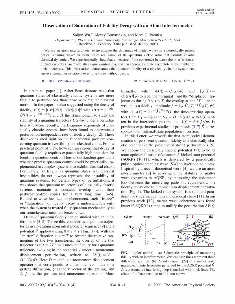
Decay of quantum fidelity can be studied with an inter-ferometer [5–8]. To see this, consider two quantum trajec-tories in a 3-grating atom interferometer sequence [9] and a
potential V applied during 0< t < T [Fig. 1(a)]. With the‘‘mirror’’ diffraction at t ¼ T to reverse the relative mo-mentum of the two trajectories, the overlap of the twotrajectories at t ¼ 2Tþ measures the fidelity for a quantum
trajectory evolving in the potential V under a momentum
displacement perturbation, written as �VðtÞ � V �D�1VðtÞD. Here D ¼ eiQx is a momentum displacementoperator that corresponds to an atomic recoil due to agrating diffraction, Q is the k vector of the grating, andx, p are the position and momentum operators. More
formally, with jc ðtÞi ¼ U1ðtÞjc i and jc 0ðtÞi ¼U1ðtÞDjc i to label the ‘‘original’’ and the ‘‘displaced’’ tra-jectories during 0< t < T, the overlap at t ¼ 2Tþ can be
written as a fidelity amplitude f ¼ hc jU2ðTÞ�1U1ðTÞjc i,with U1;2ðTÞ ¼ Te�i
RT
0H1;2dt(T the time-ordering opera-
tor). Here H1 ¼ VðtÞ and H2 ¼ D�1VðtÞD, with VðtÞ writ-ten in the interaction picture, i.e., xðtÞ ¼ xþ pt=m. In
previous experimental studies or proposals [5–7] D corre-sponds to an internal-state population inversion.In this Letter, we provide the first atom optical demon-
stration of persistent quantum fidelity in a classically cha-otic potential in the presence of strong perturbations [5].
We choose the classically chaotic potential VðtÞ to be anatom optics realization of quantum �-kicked rotor potential(AQKR) [10,11], which is delivered by a periodicallypulsed optical standing wave (SW) to laser-cooled atoms.Inspired by a recent theoretical work [4], we use an atominterferometer [9] to investigate the stability of matterwave dynamics in AQKR, by measuring the coherenceloss between the interfering paths or, equivalently, thefidelity decay due to a momentum displacement perturba-tion (Fig. 1). The kicked rotor system is a standard para-digm for studying quantum and classical chaos [11]. In ourprevious work [12], matter wave coherence was found
intact if AQKR is timed to nullify the perturbation �VðtÞ.
FIG. 1 (color online). (a) Schematic principle of measuringfidelity with an interferometer. Vertical dash lines represent threediffraction gratings. (b) Recoil diagram [24] of a matter wavegrating echo interferometer perturbed by the AQKR potential V.A representative interfering loop is marked with thick lines. Theeffect of diffractions due to V is not shown.
PRL 103, 034101 (2009) P HY S I CA L R EV I EW LE T T E R Sweek ending17 JULY 2009
0031-9007=09=103(3)=034101(4) 034101-1 � 2009 The American Physical Society

This Letter instead investigates the coherence loss over awide range of perturbation strengths. When the repetitionrate of AQKR matches the atomic recoil frequency (quan-tum resonance [13]), we find the matter wave coherencealways saturates to a nonzero value, observable after asmany as 150 kicks, after reviving from an initial loss. Thiseffect (referred to as fidelity saturation) was predicted inthe context of an internal-state atom interferometer setup[5]. It is worth noting that semiclassically the perturbationwould lead to an exponential decay of fidelity to zero [4],since almost all classical trajectories of atoms are unstableunder our typical experimental conditions [10,11].
We use the grating echo interferometer technique basedon multipath interference effects [14,15]. The interferencepaths in Fig. 1(b) become easy to understand if we no-tice the multiple paths contributing to the interferometersignals form the same type of ‘‘loops.’’ Specifically, anoff-resonant SW diffraction at t ¼ 0 produces matterwaves in multiple orders weighted by inJnð�Þ (� is theinterferometer SW pulse area [14] and Jn is the nth orderBessel function). Adjacent diffraction orders, with theirrelative momentum reversed by the 2nd SW diffraction att ¼ T, form the smallest-area loops to interfere at t ¼ 2T.We group loops of this type and plot the relative spatialdisplacement between the two paths with a �x-t ‘‘displace-ment diagram’’ in Fig. 2(a). The �x ¼ �xðtÞ lines inFig. 2(a) will be referred to as ‘‘displacement lines,’’ whichguide peaks of the matter wave correlation function
WðP; X; tÞ ¼ Tr½�ðtÞdðP; XÞ� at P ¼ �@Q and X ¼�xðtÞ ¼ R
t0Pm dt during free evolutions. Here � is the single
atom density matrix operator, and dðP; XÞ ¼ ei=@ðP�x�X�pÞ[16]. Spatially periodic matter wave density modulationappears whenever a displacement line crosses the �x ¼ 0axis. In particular, the interferometer output ��Q ¼Wð�@Q;X ¼ 0Þ is the Fourier component of the densitymodulation at around t ¼ 2T, which can be measured witha ‘‘grating echo’’ technique [14] by monitoring a Bragg-reflected light from one traveling mode of the SW, Ea, intothe other (Eb).
The AQKR potential V [Figs. 1(b) and 2(b)] is generatedwith a pulsed SW similar to that used to make the inter-ferometer. Pulsed at t ¼ fTi; i ¼ 1 . . .Ngwith Ti ¼ Tstart þði� 1ÞTkick, the AQKR potential can be written in theinteraction picture as
VðtÞ ¼ @� cos½Q0xðtÞ�XNi¼1
�ðt� TiÞ: (1)
Here the pulse area � specifies the strength of each AQKRkick. The AQKR potential generally leads to an interfer-ometer output ~��Q with reduced amplitude [Fig. 2(b)]. The
normalized amplitude f � ~��Q=��Q corresponds to a
fidelity amplitude averaged over all the adjacent interfer-
ometer diffraction paths [Fig. 1(b)] in VðtÞ under the
perturbation �VðtÞ ¼ VðtÞ � D�1VðtÞD. The strength ofthis perturbation can be characterized by a parameter�i ¼2� sin½Q0�x0ðTiÞ=2� at each kick, with �x0ðtÞ � @Qt=m[Fig. 2(b)] to be the displacement between pairs of inter-ferometer paths. In particular, if Q0�x0ðTiÞ ¼ 2n�, i.e., ifAQKR is pulsed only when the displacement is an integermultiple of the grating constant, the perturbation is nulli-fied (�i ¼ 0) and no coherence loss is expected [12].Here we use the displacement diagram in Fig. 2(b) to
generally examine the interferometer coherence loss: Thematter wave coherence that contributes to the interferome-ter signal is given by WðP;X; tÞ along the original dis-placement line �x0ðtÞ. Thus f is equal to the fraction of thesurviving coherence along �x0ðtÞ after the AQKR interac-tion. It is easy to show that a SW impulse at t generallyleads to [16]
WðP;X; tþÞ ¼ Xn
Jn
�2� sin
Q0X2
�WðP� n@Q0; X; t�Þ;
(2)
i.e., each SW kick corresponds to a ‘‘diffraction’’ ofWðP; X; tÞ by multiples of @Q0 along its P axis, graphicallyleading to multiple displacement lines with different slopeson the �x� t diagram. We iteratively apply Eq. (2) foreach kick of AQKR at t ¼ Ti to obtain the fraction of thecoherence surviving the AQKR interaction as
f ¼ Xfnig
YNi¼1
Jni½2� sinðQ0Xfnigi =2Þ�: (3)
Here Xfnigi ¼ �x0ðTiÞ þ s @Q0
m Tkick (with integer s) gives the
displacement between a pair of diffraction orders duringAQKR kicks. The sum is restricted to fnig satisfyingP
ini ¼ rN ¼ 0,P
iði� 1Þni ¼ sN ¼ 0, which specifiesthe paths in the network of displacement lines [Fig. 2(b)]that begin and end with �x0ðtÞ ¼ @Qt=m.Equation (3) can be significantly simplified when Tkick is
chosen equal to an integer multiple of the half-Talbot time
T1=2 ¼ �=!Q0 (quantum resonance), so that Xfnigi ¼
�x0ðTiÞ, up to an integer multiple of kicked rotor SWgrating constant. The parameter �i can then be used tocharacterize the perturbation strength for all pairs of pathsrepresented by the displacement lines in Fig. 2(b) gener-ated by AQKR, apart from the original displacement line�x0ðtÞ generated by the first interferometer SW pulse. Werewrite the Bessel functions in integral form and perform
FIG. 2 (color online). (a) Diagram for the relative displace-ment between pairs of wave packets along the interfering loopsof interest in Fig. 1(b). (b) Displacement diagram of the inter-ferometer in the presence of AQKR potential V.
PRL 103, 034101 (2009) P HY S I CA L R EV I EW LE T T E R Sweek ending17 JULY 2009
034101-2

the summation. If Q � Q0 so that �i � � ¼2� sinð!QTstartÞ [17], Eq. (3) at quantum resonances can
be written as
fQRð�;NÞ ¼ 1
2�
Z �
��J0
��sinðNy=2Þsinðy=2Þ
�dy: (4)
Equation (4) is remarkable: as suggested in Ref. [5], at the
large N limit fQR ¼ R�=2��=2 J0½� secð�Þ=2�2d�=�> 0;
i.e., matter wave fidelity always saturates to a nonzerovalue, in the presence of the perturbation with arbitrarystrength � and regardless of whether or not the AQKRdynamics are classically chaotic [18].
Below we will show that our experimental results areconsistent with this theoretical prediction. The experimen-tal setup is similar to that in Refs. [12,19,20].Approximately 107 laser-cooled 87Rb atoms in theirground state F ¼ 1 hyperfine level are loaded into a mag-netic guide oriented along ex, resulting in a cylindricallyshaped atom sample 1 cm long and 170 �m wide at atemperature of 25 �K. The interferometer SW, with kvector precisely aligned along ex, is formed by counter-propagating light Ea and Eb, detuned 120 MHz to the blueside of the F ¼ 1 ! F0 ¼ 2 D2 transition. The inte-rferometer SW is pulsed for 300 ns at t ¼ 0 and t ¼ T[Fig. 1(b)], with typical pulse area� � 1:5 at less than 3%spontaneous scattering probability. The total interrogationtime 2T is chosen to be 6.066 ms or 12.165 ms.
The AQKR pulses are delivered by a different standingwave that is formed by retroreflecting a traveling laserbeam that is 6.8 GHz detuned to the red side of the F ¼1 ! F0 ¼ 2 D2 transition, and is 40 mrad misaligned fromthe ex direction. The projection of AQKR k vector alongthe interferometer SW direction ex gives ð!Q �!Q0 Þ=!Q � 1:6� 10�3 that will be ignored in this Letter
[17]. The SW field is pulsed at t ¼ Ti according to Eq. (1)[Fig. 1(b)], with 500 ns duration and has a typical pulsearea �� 0:1–1:3. Our previous work has shown that themagnetic confinement introduces negligible perturbationto the matter wave interference along ex [19,20]. Here wetake advantage of the confinement to maintain the 170 �mtransverse atomic sample distribution within the 2-mm-diameter of the AQKR laser beam, allowing very consis-tent AQKR interactions for time longer than 6 ms. The‘‘grating echo’’ signal amplitude is retrieved at around t ¼2T using a heterodyne technique [14,19], and recorded inrepeated experiments as chosen parameters of AQKR arescanned. To obtain f ¼ fð�; fTigÞ, we normalize the grat-ing echo amplitude with the amplitude when no AQKRpulse is applied. The half-Talbot time T1=2 � 33:2 �s andthe pulse area � are estimated by comparing experimentaldata with Eq. (3). Since � is proportional to the SWintensity, we determine the relative magnitudes of � atdifferent SW intensities with a photodiode.
To verify the fidelity saturation predicted by Eq. (4), wefix the pulse separation at T1=2 ¼ 33:2 �s (normalized
kicking period � ¼ !QTkick ¼ �), the perturbation
strength � ¼ 2� sinð!QTstartÞ, and collect the normalized
interferometer output f as a function of the number ofkicked rotor pulses N. Figure 3(a) shows four scatter plotsfor � ¼ 0:6, 1.1, 1.5, 2.1 and 1 N 60. Here each �corresponds to a different Tstart at a fixed � ¼ 1:22ð10Þ,which was determined by comparing the photodiode read-outs with those from other experiments, as will be de-scribed below. The solid curves are derived from Eq. (4)in the absence of free parameters. From Fig. 3(a) we see apartial loss, revival, and saturation of f with increasing Nfor all strengths�. One can see from the figure that the lossand revival of coherence at small N happens more rapidlyas� increases. For� ¼ 2:1, the normalized interferometeroutput f at N ¼ 3 is almost equal to the saturation value.Having confirmed that the coherence of the interferome-
ter as a function of the number of applied kicks N shows arevival and approach to a finite asymptote, we study thisasymptotic coherence as a function of the perturbationstrength � by varying Tstart at a fixed large number ofkicks. Typical results are shown in Fig. 3(b) again for thecase where � ¼ 1:22, together with a solid curve by Eq. (4)evaluated at N ! 1. The data for N ¼ 20 kicks [circles,Fig. 3(b)] match the asymptotic theoretical curve very well(see Fig. 2 in Ref. [5]) over the achieved range of 0<�<2:44ð20Þ. For as many as N ¼ 150 kicks [triangles,Fig. 3(b)], we only observe a 40%, Tstart-independent de-crease of the interferometer signal. This additional coher-ence loss is likely related to our experimental imperfec-tions, including losses and transverse excitations of guidedatoms induced by the large number of kicks. We also plotthe same data directly vs Tstart in the inset of Fig. 3(b),which exhibits recoil frequency oscillations as expectedfrom Eq. (4).To illustrate the periodic dependence of the saturation
effect on Tkick, we plot the normalized interferometer out-put, f, as a function of both � and N in Fig. 4. The densityplot in Fig. 4(a) composes 40� 80 data points, which scan0:42� � 2:6�, and 1 N 40. [The value of f vsNat � ¼ �, 2� in Fig. 4(a) provides the type of plots inFig. 3(a)]. At a fixed �, Fig. 4 shows that f generally
FIG. 3 (color online). Normalized interferometer output f at�=� ¼ 1. Scatter plots give experimental data. Solid lines arecalculated according to Eq. (4). (a) f vs N. (b) f vs �. The insetgives the same experimental data plotted vs =�; here ¼!QTstart.
PRL 103, 034101 (2009) P HY S I CA L R EV I EW LE T T E R Sweek ending17 JULY 2009
034101-3

reduces from unity at N ¼ 0 to zero as N increases.However, we see multiple bright fringes of high f valuethat, with increasing N, become more narrowly confinedaround the quantum resonances � ¼ �, 2� without sig-nificant decay. Here the SW pulse area is estimated to be� ¼ 0:7 by comparing the measured f with Eq. (3), withwhich we obtain the simulation results in Fig. 4(b). Thetwo figures show good agreement both for small N, and for� around �, 2�. Details of the features in the plot near thequantum resonances vary with Tstart [12]. The origin of thediscrepancies at � far away from �, 2� is not yet clear, butmay be related to the increased energy transfer between theguided atoms and the pulsed SW when the quantum reso-nance condition is not met [10].
By relating atom interferometer coherence loss withfidelity decay of matter waves under a momentum dis-placement perturbation, we have presented the first experi-mental study of matter wave fidelity decay in a �-kickedrotor potential [4]. Because of the momentum displace-ment and the resulting spatial displacement between theinterferometer paths, a loss of matter wave coherence inthe spatially varying AQKR potential could be expected.However, the revival and saturation of the coherence to anonzero asymptote, as predicted by Ref. [5] in a similarcontext, is very counterintuitive semiclassically [4] if thecorresponding classical motion is chaotic [18] and theperturbation is nonzero. We have shown, with a full quan-tum treatment, that the saturation of the fidelity is due tothe localization of wave coherence scattered by AQKRkicks in a network [Fig. 2(b)]. The effect is also relatedto the stability of a ‘‘pseudoclassical standard map’’ [5,21],as seen by evaluating Eq. (3) near quantum resonances.
Previous experimental investigations on AQKR havemostly addressed the evolution of the atomic momentumdistribution [10]. It can be shown that the fidelity saturationeffect observed in this Letter is accompanied with a certaindistribution of the matter wave correlation functionWðP; XÞ, which is invariant under the iteration given inEq. (2) induced by each AQKR kick [22]. This invariantdistribution of matter wave coherence complements thestable momentum distribution near quantum resonances[10,21,23], and may be further explored for applicationsin interferometric measurements.
We thank E. J. Su for contributions to the interferometrysetup, and Dr. C. Petitjean and Professor E. J. Heller forhelpful discussions. This work is supported by MURI andDARPA from DOD, ONR, and the U.S. Department of theArmy, Agreement No. W911NF-04-1-0032, by NSF, andby the Charles Stark Draper Laboratory.
*[email protected][1] A. Peres, Phys. Rev. A 30, 1610 (1984).[2] A. Jalabert et al., Phys. Rev. Lett. 86, 2490 (2001);
F. Cucchietti et al., Phys. Rev. Lett. 91, 210403 (2003).[3] T. Prozen et al., Phys. Rev. Lett. 94, 044101 (2005);
T. Gorin et al., Phys. Rep. 435, 33 (2006).[4] C. Petitjean et al., Phys. Rev. Lett. 98, 164101 (2007).[5] S. Wimberger et al., J. Phys. B 39, L145 (2006).[6] F. Haug et al., Phys. Rev. A 71, 043803 (2005).[7] H.M. Pastawski et al., Phys. Rev. Lett. 75, 4310 (1995);
N. Friedman et al., Phys. Rev. Lett. 86, 1518 (2001);S. Schlunk et al., Phys. Rev. Lett. 90, 054101 (2003);M. Andersen et al., Phys. Rev. Lett. 97, 104102 (2006).
[8] Previous atom interferometry experiments have illustratedhow decoherence emerges as soon as ‘‘whichway in-formation’’ is generated due to the coupling between theatom with the environmental degrees of freedom. Forexample, M. Chapman et al., Phys. Rev. Lett. 75, 3783(1995); H. Uys et al., Phys. Rev. Lett. 95, 150403 (2005).
[9] Atom Interferometry, edited by P. R. Berman (AcademicPress, Cambridge, 1997).
[10] For example, F. Moore et al., Phys. Rev. Lett. 75, 4598(1995); C. Ryu et al., Phys. Rev. Lett. 96, 160403 (2006).
[11] B. V. Chirikov, Phys. Rep. 52, 263 (1979).[12] A. Tonyushkin et al., Phys. Rev. A 79, 051402(R) (2009).[13] F.M. Izrailev and D. L. Shepelyanskii, Teor. Mat. Fiz. 43,
417 (1980) [Theor. Math. Phys. 43, 553 (1980)]; F.M.Izrailev et al., Theor. Math. Phys. 43, 553 (1980).
[14] S. B. Cahn et al., Phys. Rev. Lett. 79, 784 (1997);D. Strekalov et al., Phys. Rev. A 66, 023601 (2002).
[15] J. F. Clauser et al., Appl. Phys. B 54, 380 (1992).[16] WðP;XÞ is referred to as Weyl function. See S. Chountasis
and A. Vourdas, Phys. Rev. A 58, 848 (1998); S. Wu,P. Striehl, and M.G. Prentiss, arXiv:0710.5479.
[17] With L the length of atomic sample along x, we assumeðQ�Q0ÞL 1 so that a distinction between the diffrac-tions due to the interferometer SW and the kicked rotorSW can be made. On the other hand, ð!Q�!Q0 ÞNTkick�1 is required for Eq. (4) to be approximately valid. Bothrequirements are satisfied in this work.
[18] The classical motion of atoms is controlled by the pa-rameter K ¼ 2�!QTkick. Nearly complete chaos (i.e., withnearly no stable orbit in phase space) emerges for K > 4[10,11].
[19] S. Wu, Ph. D. thesis, Harvard University, 2007.[20] S. Wu et al., Phys. Rev. Lett. 99, 173201 (2007); E. J. Su
et al., arXiv:physics/0701018.[21] S. Fishman et al., Phys. Rev. Lett. 89, 084101 (2002).[22] To see this, one needs to evaluate the sum in Eq. (3) with
general rN and sN . This will be given in a future publica-tion.
[23] C. F. Bharucha et al., Phys. Rev. E 60, 3881 (1999).[24] R. Friedberg et al., Phys. Rev. A 48, 1446 (1993).
FIG. 4 (color online). (a) Normalized interferometer output jfjwith �=� and N. Here !QTstart=� ¼ 0:5. (b) Simulation of jfjusing Eq. (3) with � ¼ 0:7.
PRL 103, 034101 (2009) P HY S I CA L R EV I EW LE T T E R Sweek ending17 JULY 2009
034101-4