oblique shocks - gerald condon · gas dynamics! oblique shock and expansion waves! • the flow...
TRANSCRIPT

Gas Dynamics 1
Oblique Shocks

Gas Dynamics
Oblique shock and expansion waves
• Mach waves can be either compression waves (p2 > p1) or expansion waves (p2 < p1), but in either case their strength is by definition very small (|p2 − p1| ≪ p1).
• A body of finite thickness, however, will generate oblique waves of finite strength, and now we must distinguish between compression and expansion types.
• The simplest body shape for generating such waves is – a concave corner, which generates an oblique shock (compression), or – a convex corner, which generates an expansion fan.
2

Gas Dynamics
Oblique shock and expansion waves
• The flow quantity changes across an oblique shock are in the same direction as across a normal shock, and across an expansion fan they are in the opposite direction.
• One important difference is that po decreases across the shock, while the fan is isentropic, so that it has no loss of total pressure, and hence po2 = po1 .
3

Gas Dynamics
Oblique Shock Waves
• The figure shows an oblique shock wave produced when a supersonic flow is deflected by an angle. We can think of the deflection as caused by a planar ramp at this angle although it could be generated by the blockage produced by a solid body placed some distance away in the flow.
4
Therefore almost all of the normal shock relations can be converted to oblique shock relations with the substitution

Gas Dynamics
Governing Equations
5

Gas Dynamics
FLOW DEFLECTION VERSUS SHOCK ANGLE
6
From the velocity triangles :

Gas Dynamics
Flow deflection versus shock angle for oblique shocks
7
At point (a) the flow is perpendicular to the shock wave and the properties of the flow are governed by the normal shock relations. In moving from point (a) to (b) the shock weakens and the deflection of the flow behind the shock increases until a point of maximum flow deflection is reached at (b). The Mach number behind the shock is subsonic up to point (c) where the Mach number just downstream of the shock is one.
Mach angle

Gas Dynamics
An Example
• With the information shown in Figure, we proceed to compute the conditions following the shock.
8

Gas Dynamics
Solution
9

Gas Dynamics
Solution (cont.)
10
For the conditions in this Example, compute the stagnation pressures and temperatures.
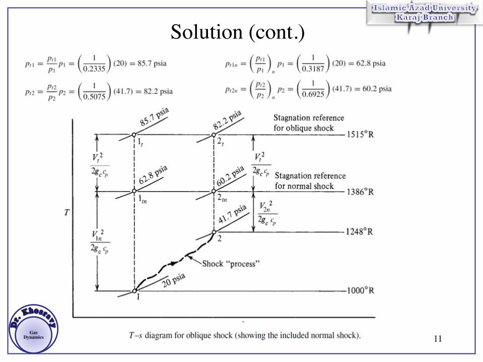
Gas Dynamics 11
Solution (cont.)

Gas Dynamics
Oblique Shock Chart
12

Gas Dynamics
Reflection of Oblique Shock
• An oblique shock is assumed to generated from a body that turns the flow through an angle δ as shown in the figure.
• The entire flow on passing through this wave is then turned “downwards” through an angle δ .
• However, the flow adjacent to the lower flat wall must be parallel to the wall. This is only possible if a “reflected” wave is generated, as shown in the following figure, that turns the flow back “up” through δ .
13

Gas Dynamics 14

Gas Dynamics
• Since the flow downstream of the “reflected” wave must again be parallel to the wall, both waves must produce the same change in flow direction. Thus, in order to determine the
• properties of this reflected wave, the following procedure is used: 1. For the given M1 and δ determine M2 and p2 / p1. 2. For this value of M2 and since the turning angle of the second wave is also δ determine M and p3 / p2. 3. The overall pressure ratio is then found from:
• 4. The angle that the reflected wave makes with the wall is β2 + δ and since β2 was found in step 2, this angle can be determined.
15

Gas Dynamics
An Example
16
Solution

Gas Dynamics
Solution (Cont.)
17

Gas Dynamics
Solution (Cont.)
18

Gas Dynamics
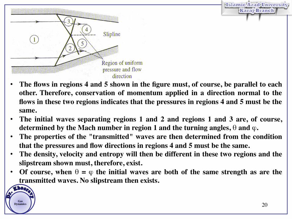
INTERACTION OF OBLIQUE SHOCK WAVES • It will be noted from the results and discussion given about the
properties of oblique shock waves that: 1. An oblique shock wave always decreases the Mach number, 2. The shock angle, β , (considering only the non-strong shock solution) for a given turning angle, δ, increases with decreasing Mach number.
19
Gas Dynamics 20
• The flows in regions 4 and 5 shown in the figure must, of course, be parallel to each other. Therefore, conservation of momentum applied in a direction normal to the flows in these two regions indicates that the pressures in regions 4 and 5 must be the same.
• The initial waves separating regions 1 and 2 and regions 1 and 3 are, of course, determined by the Mach number in region 1 and the turning angles, θ and ϕ.
• The properties of the "transmitted" waves are then determined from the condition that the pressures and flow directions in regions 4 and 5 must be the same.
• The density, velocity and entropy will then be different in these two regions and the slipstream shown must, therefore, exist.
• Of course, when θ = ϕ the initial waves are both of the same strength as are the transmitted waves. No slipstream then exists.

Gas Dynamics
An Example
21
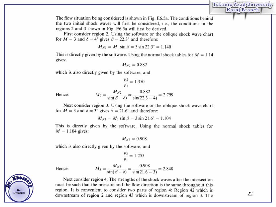
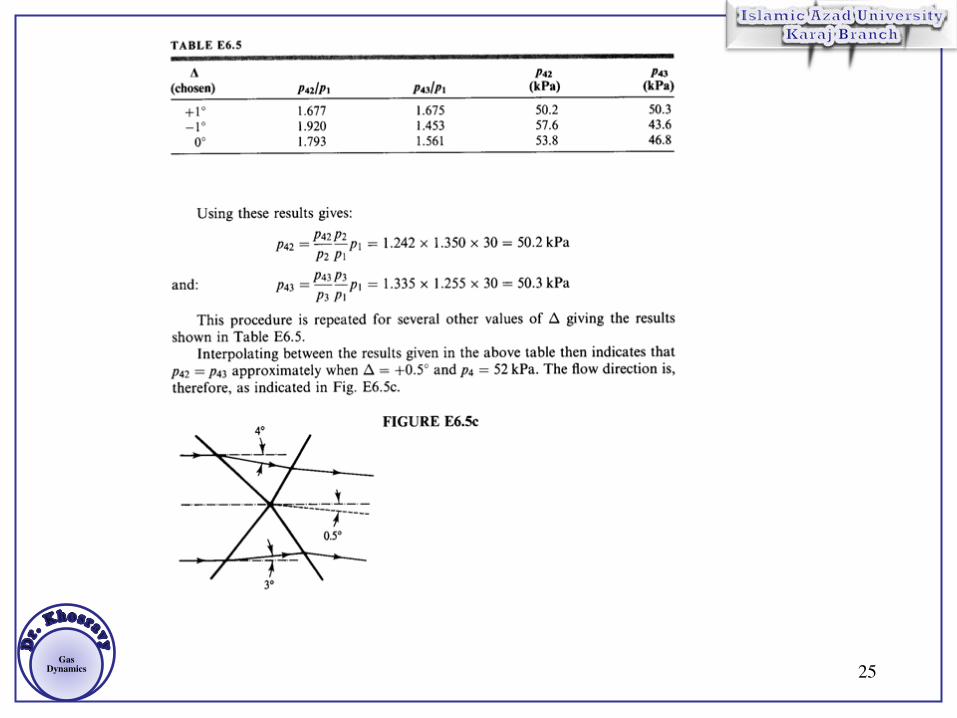
Gas Dynamics 22

Gas Dynamics 23

Gas Dynamics 24
Gas Dynamics 25