objective - human health campus - home · 2015-03-18 · iaea x ray generator • high frequency...
TRANSCRIPT
IAEAInternational Atomic Energy Agency
Slide set of 66 slides based on the chapter authored by
M.J. Jaffe and A.D.A. Maidment
of the IAEA publication (ISBN 978-92-0-131010-1):
Diagnostic Radiology Physics:
A Handbook for Teachers and Students
Objective:
To familiarize the student with the requirements and principles of
imaging of the breast using X ray mammography.
Chapter 9: Mammography
Slide set prepared
by C P Lawinski (BSc, MSc, MPhil),
London, UK

IAEA
CHAPTER 9. TABLE OF CONTENTS
9.1. Introduction
9.2. Radiological requirements for mammography
9.3. X ray equipment
9.4. Image receptors
9.5. Display of mammograms
9.6. Breast tomosynthesis
9.7. Breast CT
9.8. Computer-aided diagnosis
9.9. Stereotactic biopsy systems
9.10. Radiation dose
Bibliography
Diagnostic Radiology Physics: a Handbook for Teachers and Students – chapter 9, 2
IAEA
� Breast cancer is a major killer of women
� Over 1.38 million women diagnosed with breast cancer
internationally in 2008
• More than 458,000 deaths
� Causes not currently known
� Mortality can be significantly reduced if disease is detected
at an early stage
9.1. INTRODUCTION
Diagnostic Radiology Physics: a Handbook for Teachers and Students – chapter 9, 3

IAEA
� Mammography is a radiographic (X ray) procedure
optimized for examination of the breast
� Highly effective means of detecting early-stage breast
cancer
� Mammography is used both for
• Investigating symptomatic patients (diagnostic mammography)
• Screening of asymptomatic women (selected age groups)
� A typical mammographic screening examination consists
of one or more commonly two views of each breast
• Cranio-caudal (CC) and medial-lateral oblique (MLO)
� Other uses
• Pre-surgical localisation and guidance of biopsies.
9.2. RADIOLOGICAL REQUIREMENTS FOR MAMMOGRAPHY
Diagnostic Radiology Physics: a Handbook for Teachers and Students – chapter 9, 4
IAEA
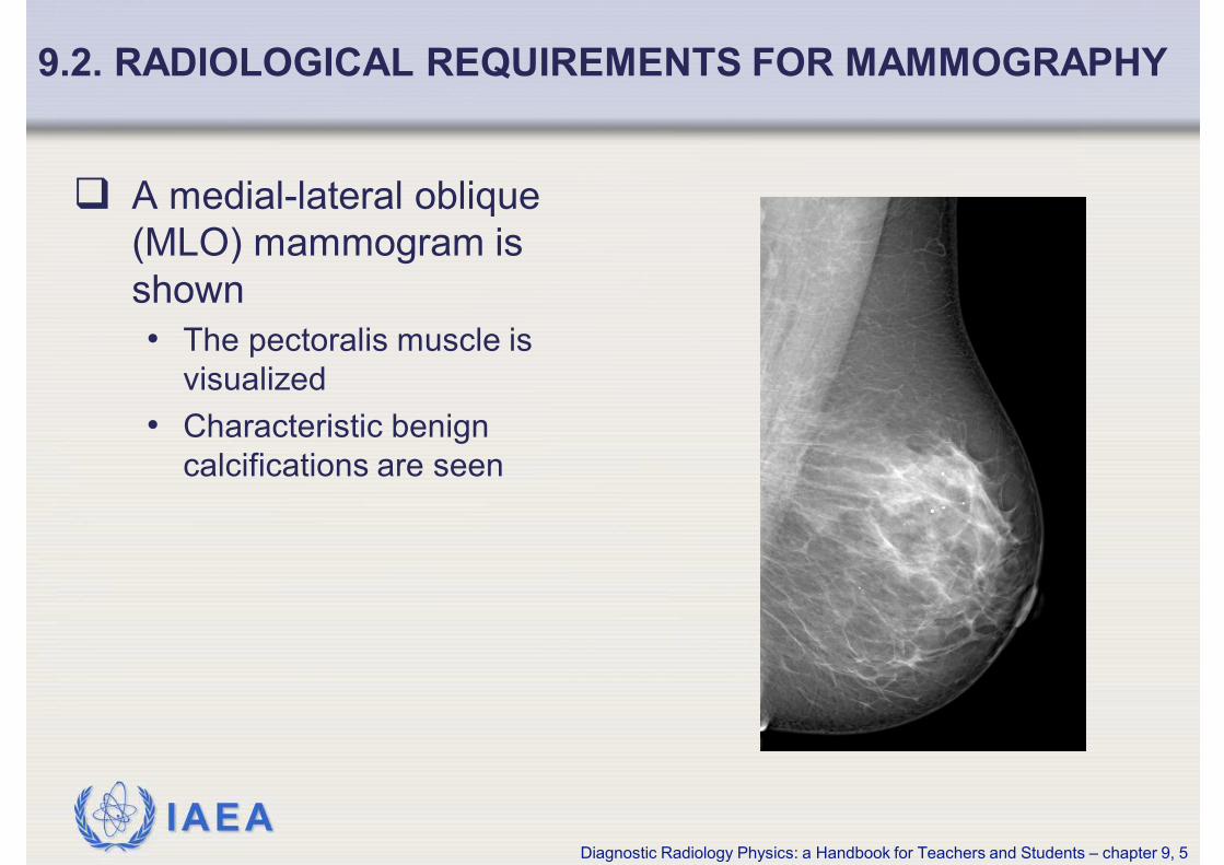
� A medial-lateral oblique
(MLO) mammogram is
shown
• The pectoralis muscle is
visualized
• Characteristic benign
calcifications are seen
9.2. RADIOLOGICAL REQUIREMENTS FOR MAMMOGRAPHY
Diagnostic Radiology Physics: a Handbook for Teachers and Students – chapter 9, 5
IAEA
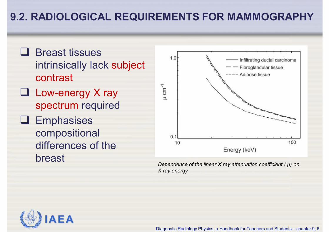
� Breast tissues
intrinsically lack subject
contrast
� Low-energy X ray
spectrum required
� Emphasises
compositional
differences of the
breastDependence of the linear X ray attenuation coefficient ( µ) on
X ray energy.
9.2. RADIOLOGICAL REQUIREMENTS FOR MAMMOGRAPHY
Diagnostic Radiology Physics: a Handbook for Teachers and Students – chapter 9, 6
IAEA
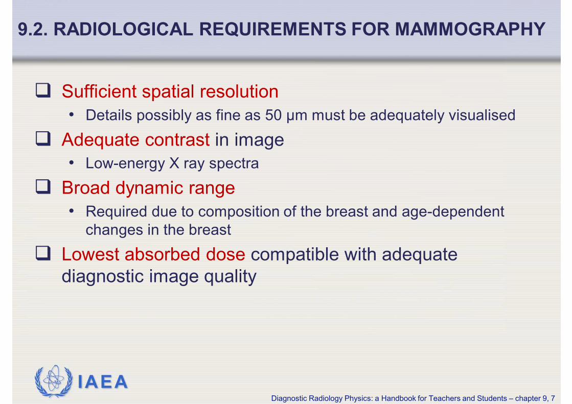
� Sufficient spatial resolution
• Details possibly as fine as 50 µm must be adequately visualised
� Adequate contrast in image
• Low-energy X ray spectra
� Broad dynamic range
• Required due to composition of the breast and age-dependent
changes in the breast
� Lowest absorbed dose compatible with adequate
diagnostic image quality
9.2. RADIOLOGICAL REQUIREMENTS FOR MAMMOGRAPHY
Diagnostic Radiology Physics: a Handbook for Teachers and Students – chapter 9, 7
IAEA
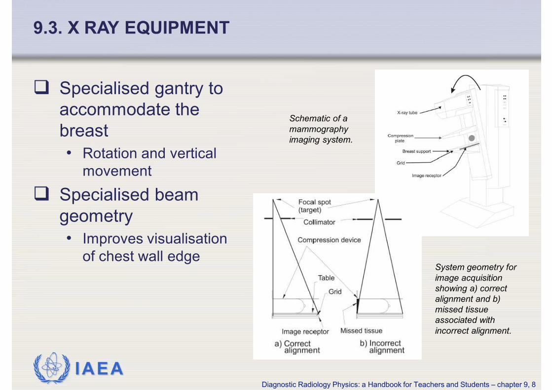
� Specialised gantry to
accommodate the
breast
• Rotation and vertical
movement
� Specialised beam
geometry
• Improves visualisation
of chest wall edge
9.3. X RAY EQUIPMENT
System geometry for
image acquisition
showing a) correct
alignment and b)
missed tissue
associated with
incorrect alignment.
Schematic of a
mammography
imaging system.
Diagnostic Radiology Physics: a Handbook for Teachers and Students – chapter 9, 8
IAEA
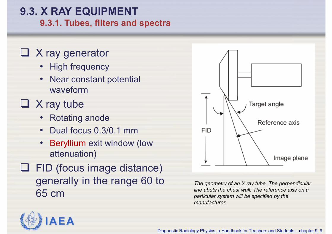
� X ray generator
• High frequency
• Near constant potential
waveform
� X ray tube
• Rotating anode
• Dual focus 0.3/0.1 mm
• Beryllium exit window (low
attenuation)
� FID (focus image distance)
generally in the range 60 to
65 cm
9.3. X RAY EQUIPMENT9.3.1. Tubes, filters and spectra
The geometry of an X ray tube. The perpendicular
line abuts the chest wall. The reference axis on a
particular system will be specified by the
manufacturer.
Diagnostic Radiology Physics: a Handbook for Teachers and Students – chapter 9, 9

IAEA
� X ray spectrum should provide a range of energies that
give an appropriate compromise between radiation dose
and image quality for the tissues under examination
� X ray spectrum determined by target material, filter
material, and tube voltage (kV)
� For screen-film mammography optimum beam energy lies
between 18 and 23 keV depending on breast thickness
and composition
• Characteristic X rays from molybdenum and rhodium are suitable
� Higher energies may be more optimal for digital
mammography
9.3. X RAY EQUIPMENT9.3.1. Tubes, filters and spectra
Diagnostic Radiology Physics: a Handbook for Teachers and Students – chapter 9, 10

IAEA
� Metallic filters used in mammography
� Molybdenum (Mo) filter (30 to 35 µm thick) commonly
employed with Mo anode
� Filter acts as energy window
• Greater attenuation of X rays at low energies and at energies above
the K-absorption edge of Mo at 20 keV
• Mo characteristic X rays from the target and X rays of similar energy
produced by bremsstrahlung pass through the filter
• Resultant spectrum enriched with X rays in the range 17 to 20 keV
� Higher energies are desirable for imaging thick, dense
breasts
• Use of Mo/Rh (molybdenum/rhodium) and Rh/Rh target/filter
combinations
9.3. X RAY EQUIPMENT9.3.1. Tubes, filters and spectra
Diagnostic Radiology Physics: a Handbook for Teachers and Students – chapter 9, 11

IAEA
9.3. X RAY EQUIPMENT9.3.1. Tubes, filters and spectra
Examples of mammographic X ray spectra.
Diagnostic Radiology Physics: a Handbook for Teachers and Students – chapter 9, 12

IAEA
� Compression should be firm but not painful
� Reasons for applying compression
• Reduces superposition of tissues
• Decreases ratio of scattered to transmitted radiation reaching the
image receptor
• Decreases the distance from any plane within the breast to the
image receptor reducing geometric unsharpness
• Compressed breast provides lower overall attenuation allowing
radiation dose to be reduced
• Compressed breast provides more uniform attenuation over the
image reducing the exposure range which must be recorded
• Provides a clamping action reducing anatomical motion during the
exposure reducing image unsharpness
9.3. X RAY EQUIPMENT9.3.2. Compression
Diagnostic Radiology Physics: a Handbook for Teachers and Students – chapter 9, 13

IAEA
� Scattered radiation reduces image quality
� Use of grid significantly decreases ratio of scattered to
transmitted radiation reaching the image receptor
� Focused linear grids (integral part of the system)
� Grid moves during exposure to blur the image of the
grid septa
• Motion must be uniform and of sufficient amplitude to avoid non-
uniformities in the image
� Bucky factor (increase in dose due to use of grid) can
be as large as 2 to 3
• Justified by improvement in image quality
9.3. X RAY EQUIPMENT9.3.3. Grids
Diagnostic Radiology Physics: a Handbook for Teachers and Students – chapter 9, 14
IAEA
� All modern mammography units are equipped with
automatic exposure control (AEC)
� Essential in order to provide the optimum dose to the
image receptor
• Target optical density for screen-film mammography
• Target SNR (signal-to-noise ratio) or preferably SDNR (signal-
difference-to- noise ratio) for digital mammography
9.3. X RAY EQUIPMENT9.3.4. Automatic exposure control
Diagnostic Radiology Physics: a Handbook for Teachers and Students – chapter 9, 15

IAEA
� For screen-film mammography and cassette-based digital
systems AEC sensor located behind image receptor to
avoid a shadow on the image
� Sensor terminates exposure when pre-set amount of
radiation received by the image receptor
� Location of sensor adjustable
• Can be positioned below appropriate region of the breast
� AEC generally microprocessor controlled
• Correction for reciprocity law failure of the film
• Automatic selection of exposure parameters (kV, filter, target)
depending on breast thickness and composition
• Sensing of breast thickness (compression device) and attenuation (short
(typically <100 ms) X ray pre-exposure)
9.3. X RAY EQUIPMENT
9.3.4. Automatic exposure control
Diagnostic Radiology Physics: a Handbook for Teachers and Students – chapter 9, 16
IAEA
� For digital mammography the digital detector can act as
the AEC sensor
� Pre-exposure concept typically used
• Entire low-dose image captured by the digital detector
• Image analysed to determine the overall SDNR or minimum SDNR
over small (~1cm2) region-of-interest (roi) in the image
• Target, filter and kV selected automatically to give desired SDNR
when main exposure performed
• As digital detectors can be operated at a wide range of input dose
levels, possible to optimize imaging according to a priority of
SDNR, low dose or a combination.
� Development in this area is on-going
• Location of the edges or critical areas of breast identified
automatically
9.3. X RAY EQUIPMENT
9.3.4. Automatic exposure control
Diagnostic Radiology Physics: a Handbook for Teachers and Students – chapter 9, 17
IAEA
� Magnification mammography can be used to improve the
diagnostic quality of the image
� Breast supported above the image receptor
• Focus object distance reduced
• Object to image receptor distance increased
• Magnification results
� Benefits of magnification mammography
• Increased SNR
• Improved spatial resolution
• Dose-efficient scatter rejection.
9.3. X RAY EQUIPMENT
9.3.5. Magnification mammography
Diagnostic Radiology Physics: a Handbook for Teachers and Students – chapter 9, 18
IAEA
� Main benefit of magnification is to increase the size of the
projected anatomic structures compared to the granularity
of the image
• SNR in the image is improved
• Improvement can be valuable, particularly for the visualization of
fine calcifications and spiculations
� Magnification in digital mammography
• Film grain noise eliminated
• Limiting spatial resolution of detector lower than that provided by
the screen-film image receptor
• Benefits of magnification may be different in nature
• Increase in projected size of anatomical features does improve the
effective resolution of the detector, which in some cases is a
limiting factor
9.3. X RAY EQUIPMENT9.3.5. Magnification mammography
Diagnostic Radiology Physics: a Handbook for Teachers and Students – chapter 9, 19
IAEA
� Spatial resolution in magnification mammography is limited
by focal spot size
• Use of a small spot (typically 0.1 mm) is critical
� As the breast is closer to the X ray source in magnification
mammography
• Dose to breast increases (compared to contact mammography)
• Air gap between the breast and image receptor provides some
scatter rejection
• Anti-scatter grids not employed for magnification (partially offsets
increase in dose)
9.3. X RAY EQUIPMENT
9.3.5. Magnification mammography
Diagnostic Radiology Physics: a Handbook for Teachers and Students – chapter 9, 20

IAEA
9.3. X RAY EQUIPMENT
9.3.5. Magnification mammography
A suspicious region is visible in the lower aspect of the mammogram (left). A magnified
image of this region obtained with focal compression shows an obvious mass (right).
Diagnostic Radiology Physics: a Handbook for Teachers and Students – chapter 9, 21
IAEA
� Screen-film mammography
� Digital mammography
• Area detectors
• Indirect detectors
• Direct detectors
• Photo-stimulable phosphors (computed radiography or CR)
• Scanning detectors
• Photon counting detectors
9.4. IMAGE RECEPTORS
Diagnostic Radiology Physics: a Handbook for Teachers and Students – chapter 9, 22

IAEA
� Single back intensifying screens used with single emulsion
radiographic film enclosed in a light-proof cassette
� High resolution fluorescent intensifying screen
• Absorbs X rays
• Converts the pattern of X rays into an optical image
� Two sizes of film typically available
• 18 cm x 24 cm and 24 cm x 30 cm
� Customary to use the smallest possible size which
ensures complete coverage of the breast
• Superior breast positioning and compression
� Women with large breasts, may require multiple films to
image the breast fully
9.4. IMAGE RECEPTORS9.4.1. Screen-film mammography
Diagnostic Radiology Physics: a Handbook for Teachers and Students – chapter 9, 23

IAEA
� Screen and film are arranged in the cassette as shown
(next slide)
� X rays must pass through cover of the cassette and the
film to impinge upon the screen
• As absorption is exponential, a larger fraction of the X rays are
absorbed and converted to light near the entrance surface of the
screen
• By minimizing the distance that the light must travel before being
collected by the film, blurring due to lateral spreading is reduced
• Spatial resolution is improved
• To further discriminate against light quanta travelling along long
oblique paths, the phosphor material may be treated with a dye
which absorbs much of this light, giving rise to a sharper image
9.4. IMAGE RECEPTORS9.4.1. Screen-film mammography
Diagnostic Radiology Physics: a Handbook for Teachers and Students – chapter 9, 24

IAEA
Configuration for a mammographic screen-film image
receptor. A single-emulsion radiographic film is held in close
contact with a fluorescent screen in a light-proof cassette.
9.4. IMAGE RECEPTORS9.4.1. Screen-film mammography
Diagnostic Radiology Physics: a Handbook for Teachers and Students – chapter 9, 25
IAEA
� Typical phosphor used for screen-film mammography is
gadolinium oxysulphide (Gd2O2S:Tb)
� Phosphor material is dense
• Quantum detection efficiency (fraction of incident X rays which
interact with the screen) is reasonably high
• Approximately 60% for a typical screen thickness and X ray spectrum
� Conversion efficiency (fraction of absorbed X ray energy
converted to light) exceeds 10% (high for a phosphor)
� Photographic film emulsion for mammography is matched
to be sensitive to:
• Spectrum of light emitted from the particular phosphor screen
• Range of X ray fluence exiting the breast
9.4. IMAGE RECEPTORS9.4.1. Screen-film mammography
Diagnostic Radiology Physics: a Handbook for Teachers and Students – chapter 9, 26

IAEA
� Important to examine the overall characteristics of the
screen and film combination rather than those of the
individual components
� Compression of the breast reduces overall range of X ray
fluence exiting the breast
• Allows films with high gradient to be used
• Enhances contrast between subtly varying soft-tissue structures
� In addition, mammography film has a high Dmax (4.0 to 4.8
OD)
• Maximizes exposure latitude over which the high gradient exists
• Important near the periphery of the breast (skin edge) where its
thickness decreases rapidly
• Nevertheless, some regions of the mammogram will generally be
under or overexposed, i.e. rendered with sub-optimal contrast.
9.4. IMAGE RECEPTORS9.4.1. Screen-film mammography
Diagnostic Radiology Physics: a Handbook for Teachers and Students – chapter 9, 27

IAEA
Characteristic curve of a film emulsion used for mammography.
9.4. IMAGE RECEPTORS9.4.1. Screen-film mammography
Diagnostic Radiology Physics: a Handbook for Teachers and Students – chapter 9, 28
IAEA
� Mammography film is processed in an automatic processor
similar to that used for general radiography
� Important that the development temperature, time and rate
of replenishment of the developer chemistry are compatible
with the type of film emulsion used and are designed to
maintain good contrast of the film
� Daily quality assurance is required in mammography to
ensure on-going optimal performance
� In screen-film mammography, the film must act as the
image acquisition detector as well as a storage and display
device
9.4. IMAGE RECEPTORS9.4.1. Screen-film mammography
Diagnostic Radiology Physics: a Handbook for Teachers and Students – chapter 9, 29
IAEA
� Several factors associated with screen-film mammography
can limit the ability to display the finest or most subtle details
� Sigmoidal shape of the characteristic curve results in limited
latitude (range of X ray exposures over which the film display
gradient is significant)
• If a tumour is located in a more lucent or more opaque region of the
breast, contrast displayed may be inadequate due to limited gradient
of the film
• Particularly of concern in patients whose breasts contain large
amounts of fibroglandular tissue (dense breasts)
� Effect of fixed pattern noise due to the granularity of the
phosphor screen and film emulsion
• Can impair the detectability of microcalcifications and other fine
structures
9.4. IMAGE RECEPTORS9.4.1. Screen-film mammography
Diagnostic Radiology Physics: a Handbook for Teachers and Students – chapter 9, 30
IAEA
� Digital mammography introduced commercially in 2000
• Able to overcome many of the technical limitations of screen-film
mammography
� In digital mammography, image acquisition, processing,
display, and storage are performed independently, allowing
optimisation of each
� Acquisition performed with low-noise X ray detectors with
wide dynamic range
� As the image is stored digitally:
• It can be displayed with contrast independent of the detector
properties
• Image processing techniques that are found to be useful can be
applied prior to image display
9.4. IMAGE RECEPTORS
9.4.2. Digital mammography
Diagnostic Radiology Physics: a Handbook for Teachers and Students – chapter 9, 31
IAEA
� Challenges in creating a digital mammography system
with improved performance are mainly related to the X ray
detector and the display device.
� The detector should have the following characteristics:
• Efficient absorption of the incident radiation beam
• Linear or logarithmic response over a wide range of incident
radiation intensity
• Low intrinsic noise and little-to-no fixed-pattern noise to ensure that
images are X ray quantum noise limited
• Limiting spatial resolution of the order of 5 to10 cycles/mm (50
to100 µm sampling)
• Can provide at least an 18x24 cm and preferably a 24x30 cm field
size
• Can image immediately adjacent to the chest wall
9.4. IMAGE RECEPTORS
9.4.2. Digital mammography
Diagnostic Radiology Physics: a Handbook for Teachers and Students – chapter 9, 32

IAEA
� Two main approaches in detector development
� Area detectors
• Entire image is acquired simultaneously
• Fast image acquisition
• Can be used with conventional design of mammography X ray unit
equipped with a grid to reduce scatter
� Scanning detectors
• Image is obtained by scanning the X ray beam and detector across
the breast
• Mechanically complex and longer acquisition times
• Use relatively simple detector(s)
• Good intrinsic scatter rejection
9.4. IMAGE RECEPTORS
9.4.2. Digital mammography
Diagnostic Radiology Physics: a Handbook for Teachers and Students – chapter 9, 33
IAEA
� Typical area detectors are based of an amorphous silicon
thin-film transistor (TFT) panel
• Contains a rectangular matrix of 2000 to 3000 columns by 3000 to
4000 rows of detector elements (dels)
• Each del is connected to electrical lines running along each row
and column by a TFT switch
• This array is covered by a phosphor or a photoconductor X ray
detector
9.4. IMAGE RECEPTORS
9.4.2. Digital mammography
Diagnostic Radiology Physics: a Handbook for Teachers and Students – chapter 9, 34
IAEA
� In “indirect” detectors each del includes both a light-
sensitive photodiode and a TFT switch
� The array is covered with a phosphor layer
• Typically thallium-activated CsI
� X rays transmitted by the breast are absorbed by the
phosphor and light produced is converted in the
photodiode to charge which is stored in its capacitance
� After the X ray exposure
• Readout signals sent sequentially along the lines for each row
activate corresponding switches
• The charge is transferred down the columns to readout amplifiers
and multiplexers and digitized to form the image
9.4. IMAGE RECEPTORS
9.4.2. Digital mammography
Diagnostic Radiology Physics: a Handbook for Teachers and Students – chapter 9, 35

IAEA
� This readout system allows the signals from all of the dels
to be read in a fraction of a second
• Fast image display
� The needle-like phosphor crystals of CsI behave
somewhat like fibre-optics
• Conduct the light to the photodiodes with less lateral spread than
would occur with granular phosphors
• Allows the thickness of the phosphor to be increased relative to a
granular phosphor to improve the quantum detection efficiency of
the detector without excessive loss of spatial resolution
9.4. IMAGE RECEPTORS
9.4.2. Digital mammography
Diagnostic Radiology Physics: a Handbook for Teachers and Students – chapter 9, 36
IAEA
� In “direct” detectors a similar readout strategy is used but the
phosphor is replaced with an X ray absorber composed of
amorphous selenium which is a photoconductor
� The energy of the absorbed X rays causes the liberation of
electron-hole pairs in the selenium
� The charged particles are drawn to the opposite faces of the
detector by an externally applied electric field
� To collect the signal an array of electrode pads (rather than
photodiodes) forms the dels
� Unlike the phosphor-based detectors, the electric field can
be tailored to collect the charge with minimal lateral spread
9.4. IMAGE RECEPTORS
9.4.2. Digital mammography
Diagnostic Radiology Physics: a Handbook for Teachers and Students – chapter 9, 37

IAEA
� This allows the use of a relatively thick detector to achieve
excellent quantum detection efficiency without significant
reduction in resolution at near normal incidence
� Other materials in which X ray energy is directly converted
to charge are under development
� These materials include:
• Lead iodide, zinc cadmium telluride and thallium bromide
• The higher atomic number of these materials allow the thickness of
the X ray converter to be reduced
• This can mitigate against the degradation of the MTF due to the
oblique incidence of the X rays
9.4. IMAGE RECEPTORS
9.4.2. Digital mammography
Diagnostic Radiology Physics: a Handbook for Teachers and Students – chapter 9, 38
IAEA
� Computed radiography (CR) systems can be used for
mammography
� Employs a photo-stimulable phosphor (PSP) plate housed
in a light-proof cassette
• When exposed to X rays, electrons in the crystalline material are
excited and subsequently captured by traps in the phosphor
• After exposure the plate is placed in a reader device and scanned
with a laser beam
• The energy of the laser light stimulates the traps to release the
electrons
• The transition of these electrons through energy levels in the
phosphor crystal results in the emission of light
• The light is collected by a photomultiplier tube, the signal digitised
and attributed to a particular pixel in the image
9.4. IMAGE RECEPTORS
9.4.2. Digital mammography
Diagnostic Radiology Physics: a Handbook for Teachers and Students – chapter 9, 39

IAEA
� For Mammography CR systems the resolution of the
image is determined by:
• Size of the scanning laser beam
• Underlying scatter of the readout laser light in the phosphor
• Distance between sample measurements
9.4. IMAGE RECEPTORS
9.4.2. Digital mammography
Diagnostic Radiology Physics: a Handbook for Teachers and Students – chapter 9, 40

IAEA
� Mammography CR systems differ from the general
radiography CR systems in several key areas
• Mammography CR system is designed for higher spatial resolution
• Uses a thinner phosphor material and is scanned with finer
sampling pitch (typically 50 µm)
� However, the result is less signal per pixel
� To overcome this limitation various innovations have been
developed to improve light coupling and reduce readout
noise, including:
• Dual-sided readout of the phosphor plates
• Needle-like phosphors which permit the use of thicker detectors
having superior quantum detection efficiency
9.4. IMAGE RECEPTORS
9.4.2. Digital mammography
Diagnostic Radiology Physics: a Handbook for Teachers and Students – chapter 9, 41

IAEA
� Detector systems discussed so far acquire the image by
integrating the signal from a number of X ray quanta
absorbed in the detector and digitizing this signal
� The image noise from these systems depends on:
• Poisson X ray quantum fluctuations associated with X ray
absorption
• Additional noise sources associated with the production of the
converted electronic signal
• These noise sources can arise from:
• Fluctuation in the amount of light produced in a phosphor in response to
absorption of an X ray of a particular energy or from the X ray spectrum itself
� As an alternative it is possible to count the number of
interacting quanta directly, thereby avoiding these
additional noise sources
9.4. IMAGE RECEPTORS
9.4.2. Digital mammography
Diagnostic Radiology Physics: a Handbook for Teachers and Students – chapter 9, 42
IAEA
� Typically quantum-counting detectors employ a geometry in
which the X ray beam is collimated into a slot or multi-slit
format and scanned across the breast to acquire the image
� The detector can be based on:
• Solid-state approach (electron-hole pairs are produced in a material
such as crystalline silicon)
• Pressurized gas (the signal is in the form of ions formed in the gas)
• Collection of charge signal plus amplification produces a pulse for each
interacting X ray quantum and pulses are counted to create the signal
� As the beam is collimated to irradiate only part of the breast at
a time the system has:
• Good intrinsic scatter rejection without the need for a grid
• Increased dose efficiency
9.4. IMAGE RECEPTORS
9.4.2. Digital mammography
Diagnostic Radiology Physics: a Handbook for Teachers and Students – chapter 9, 43
IAEA
� Film mammograms
• Specially designed transillumination devices
� Digital mammograms
• Computer displays and workstations
9.5. DISPLAY OF MAMMOGRAMS
Diagnostic Radiology Physics: a Handbook for Teachers and Students – chapter 9, 44
IAEA
� Specially designed transillumination devices are available
for reading film mammograms
• The luminance levels must be appropriate for reading
mammograms and sufficient to illuminate areas of interest
(luminance of at least 3000 cd m-2)
• The illuminator surface should provide diffused light of uniform
brightness
� Optimal viewing conditions essential for reviewing screen-
film mammograms
• Allows visualization of as much of the information recorded in the
mammogram as possible
� Mammograms should be interpreted under conditions that
provide good visibility, comfort, and minimal fatigue
9.5. DISPLAY OF MAMMOGRAMS9.5.1. Display of film mammograms
Diagnostic Radiology Physics: a Handbook for Teachers and Students – chapter 9, 45
IAEA
� Contrast sensitivity of the eye (ability to distinguish small
differences in luminance) is greatest when surroundings
are of about the same brightness as the area of interest
� Therefore to optimally see detail in a mammogram
• Glare should be reduced to a minimum
• Surface reflections should be avoided
• Ambient light level should be subdued and approximately that
reaching the eye through the mammogram
� Important to have a variable brightness, high output light
source to view high optical density (dark) areas on the film
mammogram
9.5. DISPLAY OF MAMMOGRAMS9.5.1. Display of film mammograms
Diagnostic Radiology Physics: a Handbook for Teachers and Students – chapter 9, 46

IAEA
� Display system plays a major role in influencing overall
performance of digital mammography
• Image quality presented to the film reader
• Ease of image interpretation
� Images viewed on a computer (“softcopy”) display
• Cathode ray tube (CRT) or more commonly LCD monitor
� Typical reporting workstation has matched pair of high
quality, high resolution monitors (normally 5 megapixel (MP))
• A 5 MP monitor is capable of displaying only a single mammogram at
full resolution
• Wide range of image manipulation tools available
• Brightness, contrast, zoom, , roam, scroll, etc.
9.5. DISPLAY OF MAMMOGRAMS
9.5.2. Display of digital mammograms
Diagnostic Radiology Physics: a Handbook for Teachers and Students – chapter 9, 47

IAEA
� “Hardcopy” images use a laser printer to produce a
printout of the digital image on transparent film
� Image brightness and contrast usually adjusted before
printing out the image making use of the controls provided
at the acquisition workstation
� “Hardcopy” images do not allowing control of image
processing operations during viewing
� Therefore, it is strongly recommended that digital
mammography images are displayed and reviewed using
a high quality “softcopy” device
9.5. DISPLAY OF MAMMOGRAMS
9.5.2. Display of digital mammograms
Diagnostic Radiology Physics: a Handbook for Teachers and Students – chapter 9, 48

IAEA
� In projection radiography tissue superposition can result in
a masking effect
� Breast tomosynthesis can provide reconstructed planar
images of sections of the breast
• Can aid in reducing the masking effect
� Breast tomosynthesis generally based on modified digital
mammography systems
• Planar digital imaging and tomosynthesis
• Tomosynthesis only
9.6. BREAST TOMOSYNTHESIS
Diagnostic Radiology Physics: a Handbook for Teachers and Students – chapter 9, 49

IAEA
� X ray tube pivots about a point
� Breast platform remains stationary
� Detector usually stationary but may also move
� Series of low-dose projection images (typically 9 to 25)
acquired over a limited range of angles (±7° to ±30°)
� X ray spectrum
• Higher energy typically employed (e.g.W/Al)
� X ray tube movement
• Continuous exposure or series of discrete exposures (“step and
shoot”)
� Total acquisition time must be minimized
• Possible image degradation due to patient motion
9.6. BREAST TOMOSYNTHESIS
Diagnostic Radiology Physics: a Handbook for Teachers and Students – chapter 9, 50
IAEA
� Planar cross-sectional images are reconstructed from the
projections using filtered back projection or an iterative
reconstruction algorithm
� Spatial resolution of tomosynthesis is anisotropic
• Highest resolution in-plane
• Relatively poor resolution between planes
� Reconstructed voxels are generally non-isotropic
• Pixel size approximately equal to the size of the del
• Reconstructed slice spacing is typically 1 mm
� Because of the limited range of acquisition angles
• Projection data do not form a complete set
• Reconstructed image is not a true 3D representation of the breast
• Possibility of artefacts in the images
9.6. BREAST TOMOSYNTHESIS
Diagnostic Radiology Physics: a Handbook for Teachers and Students – chapter 9, 51

IAEA
� Dedicated breast CT systems have been developed using
cone-beam geometry and a flat-panel X- ray detector
• Data for all of the CT slices acquired simultaneously
• Rapid image acquisition
• Pixel dimensions substantially larger than for digital mammography
or tomosynthesis
• Large number of projections
• To keep doses at an acceptable level images are generally acquired at a higher
tube voltage (50 to 80 kV)
• Very low dose per projection can result in noisy images
� Current designs provide a dedicated prone imaging table
� Breast CT can be performed without the need to compress
the breast.
9.7. BREAST CT
Diagnostic Radiology Physics: a Handbook for Teachers and Students – chapter 9, 52
IAEA
� Computer-aided diagnosis or computer-aided detection
(CAD) systems are designed to assist the film reader in
detecting breast cancers
� Computer system with sophisticated pattern recognition software• Natural adjunct to digital mammography
• Screen-film mammograms must be digitised (scanned)
� Interpretive aid used during image review
� Identifies “suspicious” features and alerts image reader• Does not replace the image reader
� CAD algorithms must be trained using sets of
mammograms for which the presence or absence of
cancers is known
9.8. COMPUTER-AIDED DIAGNOSIS
Diagnostic Radiology Physics: a Handbook for Teachers and Students – chapter 9, 53

IAEA
� Results of CAD are conveyed to the film reader by means
of an image annotated to show the computer detections
• Different symbols for different lesions
� Main use in screening mammography
• Double reading has been shown to increase the cancer detection
rate
• CAD has the potential to be a cost-effective alternative to double
reading
• CAD algorithm could be used to simulate the second film reader
• CAD has the potential to:
• Reduce the number of missed cancers
• Reduce the variability between film readers
• Improve the consistency and productivity of a single film reader
9.8. COMPUTER-AIDED DIAGNOSIS
Diagnostic Radiology Physics: a Handbook for Teachers and Students – chapter 9, 54

IAEA
� Recent research in CAD considers the combination of
information from multiple images
• Different views from the same examination
• Same view from a previous examination
• This approach more closely mimics how a film reader reads a case
• May improve the performance of a CAD scheme
� CAD may be particularly valuable in 3D breast imaging
• Large amount of image data to be considered
• CAD may be useful for automatic detection of microcalcifications
• Film reader can focus attention on more sophisticated
interpretation tasks
9.8. COMPUTER-AIDED DIAGNOSIS
Diagnostic Radiology Physics: a Handbook for Teachers and Students – chapter 9, 55

IAEA
� Stereotactic procedures are used to investigate suspicious
mammographic or clinical findings without the need for
surgical (excisional) biopsies
• Reduced patient risk, discomfort and cost
� In stereotactic biopsies, the gantry of a mammography unit
has the facility to allow a pair of angulated views of the
breast (typically at ± 15° from normal incidence) to be
obtained
� From measurements obtained from these images, the
three-dimensional location of a suspicious lesion is
determined and a needle equipped with a spring-loaded
cutting device can be accurately placed in the breast to
obtain tissue samples
9.9. STEREOTACTIC BIOPSY SYSTEMS
Diagnostic Radiology Physics: a Handbook for Teachers and Students – chapter 9, 56

IAEA
9.9. STEREOTACTIC BIOPSY SYSTEMS
The geometry for stereotactic breast biopsy is shown. The X ray tube is rotated about the
breast to produce two views. The Z-depth of an object can be determined by the lateral (X)
displacement observed between the two views.
Diagnostic Radiology Physics: a Handbook for Teachers and Students – chapter 9, 57
IAEA
� These systems may use small-format (e.g. 5 cm x 5 cm)
digital detectors or full-field digital detectors
� Stereotactic procedures can be performed on a
conventional mammography unit with a stereotactic
attachment with the patient standing
� Dedicated stereotactic units where the patient lies prone
on a table with the breast pendant through an aperture in
the table top into the imaging region are also available
9.9. STEREOTACTIC BIOPSY SYSTEMS
Diagnostic Radiology Physics: a Handbook for Teachers and Students – chapter 9, 58
IAEA
� Three dosimetric quantities used in mammography
• Incident air kerma (IAK), Ki
• Entrance surface air kerma Ke
• Mean glandular dose (MGD, mean dose to the glandular tissue of
the breast), DG
� MGD is the primary quantity of interest related to the risk
of radiation induced cancer in breast imaging
� MGD is calculated using factors obtained experimentally or
by Monte Carlo radiation transport calculations
� IAK (measured) converted to MGD for a breast of specific
composition and size
• Conversion coefficients are tabulated in various publications
(including IAEA Technical Report TRS-457)
9.10. RADIATION DOSE
Diagnostic Radiology Physics: a Handbook for Teachers and Students – chapter 9, 59
IAEA
� Dose in mammography depends on the size and
composition of the breast as well as the imaging device
and exposure settings selected
� In screen-film mammography goal is to maintain a target
value of optical density
� Ke increases as the thickness and/or density of the breast
increase resulting in a corresponding increase in MGD
� Increase in beam energy (tube voltage, target/material
combination) will mitigate against some of dose increase
• Image contrast will be reduced and at some point this will become
unacceptable
9.10. RADIATION DOSE
Diagnostic Radiology Physics: a Handbook for Teachers and Students – chapter 9, 60

IAEA
� In digital mammography goal is to maintain a target SDNR
at the detector
� Ke increases as the thickness and/or density of the breast
increase resulting in a corresponding increase in MGD
� Increase in beam energy (tube voltage, target/material
combination) will mitigate against some of dose increase
� On a digital system where contrast can be adjusted during
image display, an acceptable compromise can be
achieved at a higher energy than with screen-film imaging
� This allows the advantage of a greater relative decrease of
dose compared to film for large and/or dense breasts
9.10. RADIATION DOSE
Diagnostic Radiology Physics: a Handbook for Teachers and Students – chapter 9, 61
IAEA
� There is a risk of cancer induction associated with the
radiation doses received in mammography.
� BEIR VII report critically examined data on doses and
increased cancer incidence to develop a radiation risk
model for breast cancer
� Model can be useful in predicting the lifetime risk following
a single mammographic examination or from multiple
exposures at different ages as would occur in periodic
screening
� Risk for a woman at age 60 from a dose to the breasts of
0.004 Gy previously received from mammograms at age
45 is predicted to be 7.9 x 10⁻⁷
9.10. RADIATION DOSE
Diagnostic Radiology Physics: a Handbook for Teachers and Students – chapter 9, 62
IAEA
� For a screening regimen that consists of annual
mammography examinations from ages 40 to 55 and
biennial examination thereafter until age 74 (i.e. 25
screenings) with a dose of 3.7 mGy to both breasts, it is
estimated that in 100,000 women 86 radiation-induced
cancers will be caused resulting in 11 deaths and a loss of
136 women-years of life.
� In the same group, earlier detection through screening
would save 500 lives or 10,670 women-years, resulting in
a benefit-to-risk ratio of 47 (in lives) or 78 ( in women-
years). If the same diagnostic accuracy could be achieved
at reduced radiation dose, the benefit-to risk would
become even higher
9.10. RADIATION DOSE
Diagnostic Radiology Physics: a Handbook for Teachers and Students – chapter 9, 63
IAEA
� AMERICAN COLLEGE OF RADIOLOGY, Stereotactic
breast biopsy quality control manual, American College of
Radiology, Reston, VA (1999).
� AMERICAN COLLEGE OF RADIOLOGY, Mammography
quality control manual, American College of Radiology,
Reston, VA (1999).
� BICK, U., DIEKMANN, F., Digital mammography, Springer,
Heidelberg, Germany (2010).
� EUROPEAN COMMISSION, European Guideline for
Quality Assurance in Mammography Screening, Office for
Official Publications of the European Communities Rep.
V4.0 Luxembourg (2006). http://www.euref.org.
BIBLIOGRAPHY
Diagnostic Radiology Physics: a Handbook for Teachers and Students – chapter 9, 64

IAEA
� PRESTON, D.L., et al., Radiation effects on breast cancer
risk: a pooled analysis of eight cohorts, Radiat Res 158 2
(2002) 220-35.
http://www.ncbi.nlm.nih.gov/entrez/query.fcgi?cmd=Retriev
e&db=PubMed&dopt=Citation&list_uids=12105993.
� FERLAY, J., et al., "Cancer Incidence and Mortality
Worldwide in 2008: IARC CancerBase No. 10",
GLOBOCAN 2008 (Proc. Conf. Lyon, France, 2008),
International Agency for Research on Cancer, World
Health Organization, http://globocan.iarc.fr.
BIBLIOGRAPHY
Diagnostic Radiology Physics: a Handbook for Teachers and Students – chapter 9, 65

IAEA
� INTERNATIONAL ATOMIC ENERGY AGENCY, Quality
Assurance Programme for Screen-Film Mammography,
Human Health Series, 2, IAEA Vienna (2009).
http://wwwpub.iaea.org/MTCD/publications/PDF/Pub1381_
web.pdf.
� INTERNATIONAL ATOMIC ENERGY AGENCY, Quality
Assurance Programme for Digital Mammography, Human
Health Series 17, IAEA Vienna (2011).
� INTERNATIONAL COMMISSION ON RADIATION UNITS
AND MEASUREMENTS, Mammography - Assessment of
image quality, ICRU Rep. 82, Journal of the ICRU Vol. 9
No. 2 Bethesda, MD (2009).
BIBLIOGRAPHY
Diagnostic Radiology Physics: a Handbook for Teachers and Students – chapter 9, 66